01 M : 0409 169 993 Proposed: ammendments date concent of the author in part or in whole with out the written sheet no: Date: M7 Design Group Pty. Ltd. c Job No: A : UNIT 9, 61 WATTLE ROAD MAIDSTONE, VIC 3012 Client: At: F - 03 9317 8119 T - 03 9317 8111 copyright 2011: these drawings are not to be copied 730 12.12.11 274 BALLARAT ROAD, FOOTSCRAY ID PROPERTY GROUP TRIPLE STOREY UNIT DEVELOPMENT 20.02.13 AS PER BUILDERS REQUEST COLOUR/MERTERIAL AMENDMENT PROPOSED TRIPLE STOREY UNIT DEVELOPMENT @ 274 BALLARAT ROAD, FOOTSCRAY FOR ID PROPERTY GROUP COPYRIGHT OF THESE PLANS VESTS IN 'M7 DESIGN GROUP PTY LTD' 'M7 DESIGN GROUP PTY LTD' 'M7 DESIGN GROUP PTY LTD' 'M7 DESIGN GROUP PTY LTD' AS THE OWNER. THESE DRAWINGS AND THE INFORMATION HERON REMAINS THE PROPERTY OF 'M7 DESIGN GROUP PTY LTD' AND MAY NOT BE COPIED OR USED WITHOUT THEIR WRITTEN CONSENT. ALL MATERIALS AND WORK PRACTICES SHALL COMPLY WITH, BUT NOT LIMITED TO BUILDING ( interim ) REGULATIONS 2006, THE BUILDING CODE OF AUSTRALIA 2007 AND ALL RELEVANT CURRENT AUSTRALIAN STANDARDS ( as amended ) REFERRED TO THEREIN. SITE PLAN MEASURMENTS IN METERS - ALL OTHER MEASURMENTS IN MILLIMETERS (O.N.O) FIGURED DIMENSIONS TAKE PRECEDENCE OVER SCALED DIMENSIONS. THE BUILDER AND SUBCONTRACTORS SHALL CHECK AND VERIFY ALL DIMENSIONS, SETBACKS, LEVELS AND SPECIFICATIONS AND ALL OTHER RELEVANT DOCUMENTATION PRIOR TO THE COMMENCEMENT OF ANY WORKS. REPORT ALL DISCREPANCIES TO THIS OFFICE FOR CLARIFICATION. GENERAL SPECIFICATIONS ALL WORKS SHALL COMPLY WITH BUT NOT TO BE LIMITED TO TO FOLLOWING AUSTRALIAN STANDARDS. A.S - 1288 - 1994 GLASS IN BUILDINGS - SELECTION AND INSTULATION. A.S - 1480 CONCRETE STRUCTURES CODE. INSTULATION. A.S - 1562 - 1992 DESIGN ANDE INSTULATION OF SHEET ROOF AND WALL CLADDING. PART 1 METAL. A.S - 1684 - 1999 NATIONAL TIMBER FRAMING CODE A.S - 1860 - 1998 INSULLATION OF PARTICLBOARD FLOORING A.S - 2047 - 1999 WINDOWS IN BUILDINGS-SELECTION AND INSULLATION. A.S - 2049 - 2002 ROOF TILES. A.S - 2050 - 2002 INSULLATION OF ROOFING TILES. A.S - 2870 - 1996 RESIDENTIAL SLABS AND FOOTINGS CONSTRUCTION. A.S - 2904 - 1995 DAMP PROOF COURSES AND FLASHINGS. A.S - 3660 - 2001 CONCRETE STRUCTURES. A.S - 3660.1 - 2000 PROTECTION OF BUILDING AGAINST SUBTERRANEAN TERMITES - PART 1 NEW BUILDINGS A.S - 3700 - 2001 MASONRY STRUCTURES. A.S - 3740 - 2004 WATERPROOFING OF WET AREAS IN RESIDENTIAL BUILDINGS. A.S - 3786 - 1993 SMOKE ALARMS. A.S - 4055 - 1992 WIND LOADING FOR HOUSING A.S - 4100 - 1998 STEEL STRUCTURES A.S - 4256 - 1994/96 PLASTIC ROOF AND WALL CLADDING MATERIALS. GLAZING, INCLUDINGSFETY GLAZIN, SHALL BE INSTALLED TO A SIZE, TYPE AND THICKNESS SO AS TO COMPLY WITH: - BCA PART 3.6 FOR CLASS 1 AND 10 BUILDINGS WITHIN A DESIGN WIND SPEED OF NOTMORE THAN N3; AND - BCA PART B1.4 FO CLASS 2 AND 9 BUILDINGS. REFER TO ACOUSTIC REPORT DATED 13.09-2011 (1) ALL ROOMS - WITHIN 500mm VERTICAL OF FLOOR LEVEL (2) BATHROOMS - WITHIN 1500mm VERTICAL FROM BATH BASE - WITHIN 500mm HORIZONTAL FROM BATH/SHOWER TO SHOWER DOORS, SHOWER SCREENS AND BATH ENCLOSURES (3) LAUNDRY - WITHIN 1200mm VERTICAL FROM FLOOR LEVEL AND /OR WITHIN 300mm VERTICAL OF TROUGH (4) DOORWAYS - WITHIN 300mm HORIZONTAL FROM ALL DOORS (5) ENSUITE - AS FOR (2) WATER PROOFING OF WET AREAS, BEING BATHROOMS, SHOWER, SHOWER ROOMS, LAUNDRIES, SANITARY COMPARTMENTS AND THE LIKE SHALL BE PROVIDED IN ACCORDANCE WITH AS 3740-2004: WATERPROOFING OF WET AREAS WITHIN RESIDENTIAL BUILDINGS. SUSTAINABILITY MEASURES FOR NEW CLASS 1 BUILDINGS: UNLESS PERMITTED OTHERWISE, 5 STAR ENERGY EFFICIENCY DESIGNS SHALL BE CONSTRUCTED IN ACCORDANCE WITH THE STAMPED PLANS ENDORSED BY THE ACCREDITED ENERGY RATER WITHOUT ALTERATION, AND SHALL BE GENERALLY RATED TO COMPLY WITH THE FOLLOWING OPTIONS: (1) FOR NEW CLASS 1 BUILDINGS OTHER THAN THOSE CONSTRUCTED ON A TIMBER FLOOR OR OF EARTH WALL CONSTRUCTION: - OPTION 1: ACHIEVE A HOUSE ENERGY RATING OF 5 STAR FOR THE BUILDING FABRIC PLUS A SOLAR HOT WATER SYSTEM ACHIEVING AN ENERGY PERFORMANCE OF 60% SOLAR GAIN; OR - OPTION 2: ACHIEVE A HOUSE ENERGY RATING OF 5 STAR FOR THE BUILDING FABRIC PLUS A 2000 LITRE RAINWATER TANK ( HAVING A MINIMUM 50m2 ROOF CATCHMENT AREA ) SUPPLYING ALL SANITARY FLUSHING SYSTEMS; (2) FOR NEW CLASS 1 DESIGNED CONSTRUCTED ON TIMBER FLOOR TO GROUND FLOOR OR OF EARTH WALL CONSTRUCTION SUBSTANTIALLY DESIGNED PRIOR TO 30 APRIL 2006: - OPTION 1: ACHIEVE A HOUSE ENERGY RATING OF 5 STAR FOR THE BUILDING FABRIC; OR - OPTION 2: ACHIEVE A HOUSE ENERGY RATING OF 4 STAR FOR THE BUILDING FABRIC PLUS A SOLAR HOT WATER SYSTEM ACHIEVING AN ENERGY PERFORMANCE OF 60% SOLAR GAIN; OR - OPTION 3: ACHIEVE A HOUSE ENERGY RATING OF 4 STARS FOR THE BUILDING FABRIC PLUS A 2000 LITRE RAINWATER TANK ( HAVING A MINIMUM 50m2 ROOF CATHMENT AREA ) SUPPLYING ALL SANITARY FLUSHING SYSTEMS. INSTALLATION OF ALL SERVICES SHALL COMPLY WITH THE RESPECTIVE SUPPLY AUTHORITY REQUIRMENTS. GENERAL NOTES STEP SIZES ( OTHER THAN FOR SPIRAL STAIRS ) TO BE: RISERS (R) 190mm MAXIMUM AND 115mm MINIMUM GOINGS (G) 355mm MAXIMUM AND 240mm MINIMUM 2R + 1G = 700mm MAXIMUM AND 550mm MINIMUM 125mm MAXIMUM GAP TO OPEN TREADS ALL TREADS, LANDINGS AND THE LIKE TO HAVE NON SLIP FINISH OR SUITABLE NON- SKID STRIP NEAR EDGE OF NOSING. PROVIDE BALUSTRADES WHERE CHANGE IN LEVEL EXCEEDS 1000mm ABOVE THE SURFACE BENEATH LANDINGS, RAMPS AND/OR TREADS. BALUSTRADES ( OTHER THAN TENSIONED WIRE BALUSTRADES ) TO BE: 1000mm MIN, ABOVE FINISHED SURFACE LEVEL OF BALCONIES, LANDINGS OR THE LIKE, AND 865mm MIN, ABOVE FINISHED SURFACE LEVEL OF STAIR NOSING OR RAMP, AND VERTICAL WITH A 125mm MAXIMUM GAP BETWEEN, AND ANY HORIZONTAL ELEMENT WITHIN THE BALUSTRADE BETWEEN 150mm AND 760mm ABOVE THE FLOOR MUST NOT FACILITATE CLIMBING WHERE CHANGES IN LEVELS EXCEEDS 4000mm ABOVE THE SURFACE BENEATH LANDINGS, RAMPS AND/OR TREADS. WIRE BALUSTRADE CONSTRUTION TO COMPLY WITH BCA2007 VOLUME 2 PART 3.9.2.3 FOR CLASS 1 AND 10 BUILDINGS AND BCA2007 VOLUME 1 PART D2.16 FOR OTHER CLASSES OF BUILDINGS. HAND RAILS TO BE 865mm MINIMUM ABOVE STAIR NOSING AND LANDINGS. THESE PLANS HAVE BEING PREPARED FOR THE EXCLUSIVE USE BY THE CLIENT OF M7 DISIGN GROUP PTY LTD M7 DISIGN GROUP PTY LTD M7 DISIGN GROUP PTY LTD M7 DISIGN GROUP PTY LTD ( 'THE DESIGNER' ) FOR THE PURPOSE EXPRESSLY NOTIFIED TO THE DESIGNER. ANY OTHER PERSON WHO USES OR RELIES ON THESE PLANS WITHOUT THE DESIGNER'S WRITTEN CONSENT DOSE SO AT THEIR OWN RISK AND NO RESPOSIBILITY IS ACCEPTED BY THE DESIGNER FOR SUCH USE AND/OR RELIANCE. ALL DOOR TI BE 2040MM IN HEIGHT (U.N.O) THE APPROVAL OF THIS OFFICE OF A SUBSTITUTE MATERIAL, WORK PRACTICE, VARIATIONS OR THE LIKE IS NOT AN AUTHORISATION FOR ITS USE OR A CONTRACT VARIATION. ANY SAID VARIATIONS MUST BE ACCEPTED BY ALL PARTIES TO THE AGREEMENT AND WHERE APPLICABLE THE RELEVANT BUILDING SURVEYOR PRIOR TO IMPLEMENTING THE SAID VARIATION. WINDOW SIZES NOMINATED ARE NOMINAL ONLY. ACTUAL SIZE MAY VARY ACCORDING TO MANUFACTURER. WINDOWS TO BE FLASHED ALL AROUND. WINDOWS TO BE FLASHED AROUND WHERE THE BUILDING ( EXCLUDES CLASS 10 ) IS LOCATED IN A TERMITE PRONE AREA THE AREA TO UNDERSIDE OF BUILDING OF BUILDING AND PERIMETER IS TO BE TREATED AGAINST TERMITE ATTACK. FOR BUILDINGS IN MARINE OR OTHER EXPOSURE ENVIROMENTS SHALL HAVE MASONRY UNITS, MORTAR AND ALL BUILT IN COMPONENTS AND THE LIKE COMPLYING WITH THE DURABILITY REQUIREMENTS OF TABLE 5.1 OF AS 3700-2001 MASONRY STRUCTURES CONCRET STUMPS: UP TO 1400mm LONG TO BE 100mm x 100mm (1 No. H.D.WIRE) 1401mm TO 1800mm LONG TO BE 100mm x 100mm (2 No. H.D. WIRES) 1801mm TO 3000mm LONG TO BE 125mm x 125mm (2 No. H.D WIRES) 100mm x 100mm STUMPS EXCEEDING 1200mm ABOVE GROUND LEVEL TO BE BRACED WHERE NO PERIMETER BASE BRICKWORK PROVIDED. ALL STORMWATER TO BE TAKE TO LEGAL POINT OF DISCHARGE TO THE RELEVANT AUTHORITIES APPROVAL. STORMWATER: 100mm DIA. CLASS 6 UPVC STORMWATER LINE LAID TO A MINIMUM GRADE OF 1:100 AND CONNECT TO THE LEGAL POINT OF STORMWATER DISCHARGE. PROVIDE INSPECTION OPENINGS AT 9000mm C/C AND AT EACH CHANGE OF DIRECTION. THE COVER TO UNDERGROUND STORMWATER DRAINS SHALL BE NOT LESS THAN: 100mm UNDER SOIL 50mm UNDER PAVED CONCRETE AREAS 100mm UNDER UNREINFORCED CONCRETE OR PAVED DRIVWAYS 75mm UNDER REINFORCED CONCRETE DRIVEWAYS THESE DRAWINGS SHALL BE READ IN CONJUNCTION WITH ALL RELEVANT STRUCTURAL, GEOTECHNICAL AND ALL OTHER CONSULTANTS DRAWINGS/DETAILS AND WITH ANY OTHER WRITTEN INSTRUCTIONS ISSUED IN THE COURSE OF THE CONTRACT. THE BUILDER SHALL TAKE ALL STEPS NECESSARY TO ENSURE THE STABILITY AND GENERAL WATER TIGHTNESS OF ALL NEW AND/OR EXISTING STRUCTURES DURING ALL WORKS. THE BUILDER AND SUBCONTRACTOR SHALL ENSURE THAT ALL STORMWATER DRAINS, SEWER PIPES AND THE LIKE ARE LOCATED AT A SUFFICIENT DISTANCE FROM ANY BUILDINGS FOOTING AND/OR SLAB EDGE BEAMS SO AS TO PREVENT GENERAL MOISTURE PENETRATION, DAMPNESS, WEAKNENING AND UNDERMINING OF ANY BUILDING AND ITS FOOTING SYSTEM. SITE CLASSIFICATION: H2 SITE CLASSIFICATION AS CLASS: H REFER TO SOIL REPORT No: 111154 BY: HARDROCK GEOTECHNICAL DESIGN GUST WIND SPEED / WIND CLASSIFICATION: REGION "______ " REFER TO WIND CLASSIFICATION SYSTEM BY _______________, JOB NUMBER: _______________ BUILDING TIE-DOWNS TO BE PROVIDED IN ACCORDANCE WITH AS 1684 - 2006 FOR AN ASSUMED DESIGN GUST WIND SPEED / WIND CLASSIFICATION OF ________________________________________ ( SUBJECT TO CONFIRMATION ON SITE BY RELEVANT BUILDING SURVEYOR AT FIRST INSPECTION ) REFER TO AS1684 FOR CONSTRUCTION REQUIREMENTS. AUTHORITIES / CONSULTANTS MUNICIPALITY: NAME: SEWERAGE AUTHORITY: NAME: RELEVANT BUILDING SURVEYOR: NAME: CONSULTING STRUCTURAL ENGINEER: NAME: GEOTECHNICAL ENGINEER: NAME: MARIBYRNONG Ph: 9688 0200 CITY WEST WATER Ph: 131691 TBA D & A CONSULTING HARDROCK GEOTECHNICAL HOUSE ENERGY RATING FirstRate 5 single dwelling rating MJ/m stars multi-unit development (attach listing of ratings) Accreditation number Signature Date VIC/BDAV/11/4082 Yianni Kambour 23/11/2011 5.2 140.8 2 house energy rating software HOUSE ENERGY RATING FirstRate 5 single dwelling rating MJ/m stars multi-unit development (attach listing of ratings) Accreditation number Signature Date 2 house energy rating software HOUSE ENERGY RATING FirstRate 5 single dwelling rating MJ/m stars multi-unit development (attach listing of ratings) Accreditation number Signature Date 2 house energy rating software HOUSE ENERGY RATING FirstRate 5 single dwelling rating MJ/m stars multi-unit development (attach listing of ratings) Accreditation number Signature Date 2 house energy rating software HOUSE ENERGY RATING FirstRate 5 single dwelling rating MJ/m stars multi-unit development (attach listing of ratings) Accreditation number Signature Date 2 house energy rating software HOUSE ENERGY RATING FirstRate 5 single dwelling rating MJ/m stars multi-unit development (attach listing of ratings) Accreditation number Signature Date 2 house energy rating software HOUSE ENERGY RATING FirstRate 5 single dwelling rating MJ/m stars multi-unit development (attach listing of ratings) Accreditation number Signature Date 2 house energy rating software HOUSE ENERGY RATING FirstRate 5 single dwelling rating MJ/m stars multi-unit development (attach listing of ratings) Accreditation number Signature Date 2 house energy rating software UNIT 1 UNIT 2 UNIT 3 UNIT 4 UNIT 5 UNIT 6 UNIT 7 UNIT 8 VIC/BDAV/11/4082 Yianni Kambour 23/11/2011 VIC/BDAV/11/4082 Yianni Kambour 23/11/2011 VIC/BDAV/11/4082 Yianni Kambour 23/11/2011 VIC/BDAV/11/4082 Yianni Kambour 23/11/2011 VIC/BDAV/11/4082 Yianni Kambour 23/11/2011 VIC/BDAV/11/4082 Yianni Kambour 23/11/2011 VIC/BDAV/11/4082 Yianni Kambour 23/11/2011 5.2 138.6 5.3 137.0 5.1 144.1 5.1 143.8 5.0 146.4 5.0 147.4 5.4 134.2
Transcript
01
M : 0409 169 993
Proposed: ammendmentsdate
concent of the author
in part or in whole with out the written sheet no:Date:
M7 Design Group Pty. Ltd.
cJob No:A : UNIT 9, 61 WATTLE ROAD
MAIDSTONE, VIC 3012
Client:
At:
F - 03 9317 8119
T - 03 9317 8111
copyright 2011: these drawings are not to be copied
730 12.12.11
274 BALLARAT ROAD, FOOTSCRAY
ID PROPERTY GROUP
TRIPLE STOREY UNIT DEVELOPMENT 20.02.13 AS PER BUILDERS REQUEST
COLOUR/MERTERIAL AMENDMENT
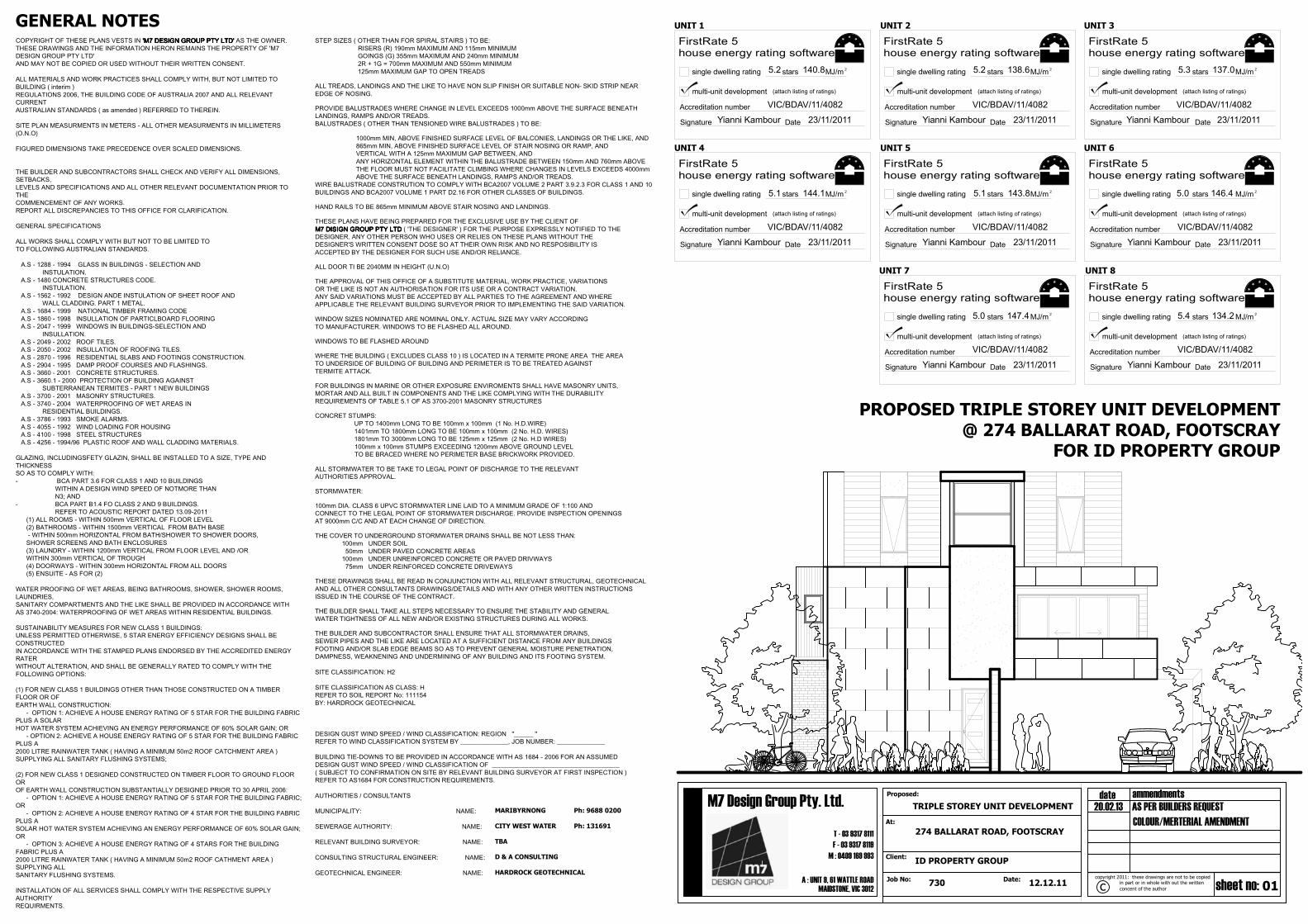
PROPOSED TRIPLE STOREY UNIT DEVELOPMENT@ 274 BALLARAT ROAD, FOOTSCRAY
FOR ID PROPERTY GROUP
COPYRIGHT OF THESE PLANS VESTS IN 'M7 DESIGN GROUP PTY LTD''M7 DESIGN GROUP PTY LTD''M7 DESIGN GROUP PTY LTD''M7 DESIGN GROUP PTY LTD' AS THE OWNER.THESE DRAWINGS AND THE INFORMATION HERON REMAINS THE PROPERTY OF 'M7DESIGN GROUP PTY LTD'AND MAY NOT BE COPIED OR USED WITHOUT THEIR WRITTEN CONSENT.
ALL MATERIALS AND WORK PRACTICES SHALL COMPLY WITH, BUT NOT LIMITED TOBUILDING ( interim )REGULATIONS 2006, THE BUILDING CODE OF AUSTRALIA 2007 AND ALL RELEVANTCURRENTAUSTRALIAN STANDARDS ( as amended ) REFERRED TO THEREIN.
SITE PLAN MEASURMENTS IN METERS - ALL OTHER MEASURMENTS IN MILLIMETERS(O.N.O)
FIGURED DIMENSIONS TAKE PRECEDENCE OVER SCALED DIMENSIONS.
THE BUILDER AND SUBCONTRACTORS SHALL CHECK AND VERIFY ALL DIMENSIONS,SETBACKS,LEVELS AND SPECIFICATIONS AND ALL OTHER RELEVANT DOCUMENTATION PRIOR TOTHECOMMENCEMENT OF ANY WORKS.REPORT ALL DISCREPANCIES TO THIS OFFICE FOR CLARIFICATION.
GENERAL SPECIFICATIONS
ALL WORKS SHALL COMPLY WITH BUT NOT TO BE LIMITED TOTO FOLLOWING AUSTRALIAN STANDARDS.
A.S - 1288 - 1994 GLASS IN BUILDINGS - SELECTION AND INSTULATION. A.S - 1480 CONCRETE STRUCTURES CODE. INSTULATION. A.S - 1562 - 1992 DESIGN ANDE INSTULATION OF SHEET ROOF AND WALL CLADDING. PART 1 METAL. A.S - 1684 - 1999 NATIONAL TIMBER FRAMING CODE A.S - 1860 - 1998 INSULLATION OF PARTICLBOARD FLOORING A.S - 2047 - 1999 WINDOWS IN BUILDINGS-SELECTION AND INSULLATION. A.S - 2049 - 2002 ROOF TILES. A.S - 2050 - 2002 INSULLATION OF ROOFING TILES. A.S - 2870 - 1996 RESIDENTIAL SLABS AND FOOTINGS CONSTRUCTION. A.S - 2904 - 1995 DAMP PROOF COURSES AND FLASHINGS. A.S - 3660 - 2001 CONCRETE STRUCTURES. A.S - 3660.1 - 2000 PROTECTION OF BUILDING AGAINST SUBTERRANEAN TERMITES - PART 1 NEW BUILDINGS A.S - 3700 - 2001 MASONRY STRUCTURES. A.S - 3740 - 2004 WATERPROOFING OF WET AREAS IN RESIDENTIAL BUILDINGS. A.S - 3786 - 1993 SMOKE ALARMS. A.S - 4055 - 1992 WIND LOADING FOR HOUSING A.S - 4100 - 1998 STEEL STRUCTURES A.S - 4256 - 1994/96 PLASTIC ROOF AND WALL CLADDING MATERIALS.
GLAZING, INCLUDINGSFETY GLAZIN, SHALL BE INSTALLED TO A SIZE, TYPE ANDTHICKNESSSO AS TO COMPLY WITH:- BCA PART 3.6 FOR CLASS 1 AND 10 BUILDINGS WITHIN A DESIGN WIND SPEED OF NOTMORE THAN N3; AND- BCA PART B1.4 FO CLASS 2 AND 9 BUILDINGS. REFER TO ACOUSTIC REPORT DATED 13.09-2011 (1) ALL ROOMS - WITHIN 500mm VERTICAL OF FLOOR LEVEL (2) BATHROOMS - WITHIN 1500mm VERTICAL FROM BATH BASE - WITHIN 500mm HORIZONTAL FROM BATH/SHOWER TO SHOWER DOORS, SHOWER SCREENS AND BATH ENCLOSURES (3) LAUNDRY - WITHIN 1200mm VERTICAL FROM FLOOR LEVEL AND /OR WITHIN 300mm VERTICAL OF TROUGH (4) DOORWAYS - WITHIN 300mm HORIZONTAL FROM ALL DOORS (5) ENSUITE - AS FOR (2)
WATER PROOFING OF WET AREAS, BEING BATHROOMS, SHOWER, SHOWER ROOMS,LAUNDRIES,SANITARY COMPARTMENTS AND THE LIKE SHALL BE PROVIDED IN ACCORDANCE WITHAS 3740-2004: WATERPROOFING OF WET AREAS WITHIN RESIDENTIAL BUILDINGS.
SUSTAINABILITY MEASURES FOR NEW CLASS 1 BUILDINGS:UNLESS PERMITTED OTHERWISE, 5 STAR ENERGY EFFICIENCY DESIGNS SHALL BECONSTRUCTEDIN ACCORDANCE WITH THE STAMPED PLANS ENDORSED BY THE ACCREDITED ENERGYRATERWITHOUT ALTERATION, AND SHALL BE GENERALLY RATED TO COMPLY WITH THEFOLLOWING OPTIONS:
(1) FOR NEW CLASS 1 BUILDINGS OTHER THAN THOSE CONSTRUCTED ON A TIMBERFLOOR OR OFEARTH WALL CONSTRUCTION: - OPTION 1: ACHIEVE A HOUSE ENERGY RATING OF 5 STAR FOR THE BUILDING FABRICPLUS A SOLARHOT WATER SYSTEM ACHIEVING AN ENERGY PERFORMANCE OF 60% SOLAR GAIN; OR - OPTION 2: ACHIEVE A HOUSE ENERGY RATING OF 5 STAR FOR THE BUILDING FABRICPLUS A2000 LITRE RAINWATER TANK ( HAVING A MINIMUM 50m2 ROOF CATCHMENT AREA )SUPPLYING ALL SANITARY FLUSHING SYSTEMS;
(2) FOR NEW CLASS 1 DESIGNED CONSTRUCTED ON TIMBER FLOOR TO GROUND FLOOROROF EARTH WALL CONSTRUCTION SUBSTANTIALLY DESIGNED PRIOR TO 30 APRIL 2006: - OPTION 1: ACHIEVE A HOUSE ENERGY RATING OF 5 STAR FOR THE BUILDING FABRIC;OR - OPTION 2: ACHIEVE A HOUSE ENERGY RATING OF 4 STAR FOR THE BUILDING FABRICPLUS ASOLAR HOT WATER SYSTEM ACHIEVING AN ENERGY PERFORMANCE OF 60% SOLAR GAIN;OR - OPTION 3: ACHIEVE A HOUSE ENERGY RATING OF 4 STARS FOR THE BUILDINGFABRIC PLUS A2000 LITRE RAINWATER TANK ( HAVING A MINIMUM 50m2 ROOF CATHMENT AREA )SUPPLYING ALLSANITARY FLUSHING SYSTEMS.
INSTALLATION OF ALL SERVICES SHALL COMPLY WITH THE RESPECTIVE SUPPLYAUTHORITYREQUIRMENTS.
GENERAL NOTESSTEP SIZES ( OTHER THAN FOR SPIRAL STAIRS ) TO BE: RISERS (R) 190mm MAXIMUM AND 115mm MINIMUM GOINGS (G) 355mm MAXIMUM AND 240mm MINIMUM 2R + 1G = 700mm MAXIMUM AND 550mm MINIMUM 125mm MAXIMUM GAP TO OPEN TREADS
ALL TREADS, LANDINGS AND THE LIKE TO HAVE NON SLIP FINISH OR SUITABLE NON- SKID STRIP NEAREDGE OF NOSING.
PROVIDE BALUSTRADES WHERE CHANGE IN LEVEL EXCEEDS 1000mm ABOVE THE SURFACE BENEATHLANDINGS, RAMPS AND/OR TREADS.BALUSTRADES ( OTHER THAN TENSIONED WIRE BALUSTRADES ) TO BE:
1000mm MIN, ABOVE FINISHED SURFACE LEVEL OF BALCONIES, LANDINGS OR THE LIKE, AND 865mm MIN, ABOVE FINISHED SURFACE LEVEL OF STAIR NOSING OR RAMP, AND VERTICAL WITH A 125mm MAXIMUM GAP BETWEEN, AND ANY HORIZONTAL ELEMENT WITHIN THE BALUSTRADE BETWEEN 150mm AND 760mm ABOVE THE FLOOR MUST NOT FACILITATE CLIMBING WHERE CHANGES IN LEVELS EXCEEDS 4000mm ABOVE THE SURFACE BENEATH LANDINGS, RAMPS AND/OR TREADS.WIRE BALUSTRADE CONSTRUTION TO COMPLY WITH BCA2007 VOLUME 2 PART 3.9.2.3 FOR CLASS 1 AND 10BUILDINGS AND BCA2007 VOLUME 1 PART D2.16 FOR OTHER CLASSES OF BUILDINGS.
HAND RAILS TO BE 865mm MINIMUM ABOVE STAIR NOSING AND LANDINGS.
THESE PLANS HAVE BEING PREPARED FOR THE EXCLUSIVE USE BY THE CLIENT OFM7 DISIGN GROUP PTY LTDM7 DISIGN GROUP PTY LTDM7 DISIGN GROUP PTY LTDM7 DISIGN GROUP PTY LTD ( 'THE DESIGNER' ) FOR THE PURPOSE EXPRESSLY NOTIFIED TO THEDESIGNER. ANY OTHER PERSON WHO USES OR RELIES ON THESE PLANS WITHOUT THEDESIGNER'S WRITTEN CONSENT DOSE SO AT THEIR OWN RISK AND NO RESPOSIBILITY ISACCEPTED BY THE DESIGNER FOR SUCH USE AND/OR RELIANCE.
ALL DOOR TI BE 2040MM IN HEIGHT (U.N.O)
THE APPROVAL OF THIS OFFICE OF A SUBSTITUTE MATERIAL, WORK PRACTICE, VARIATIONSOR THE LIKE IS NOT AN AUTHORISATION FOR ITS USE OR A CONTRACT VARIATION.ANY SAID VARIATIONS MUST BE ACCEPTED BY ALL PARTIES TO THE AGREEMENT AND WHEREAPPLICABLE THE RELEVANT BUILDING SURVEYOR PRIOR TO IMPLEMENTING THE SAID VARIATION.
WINDOW SIZES NOMINATED ARE NOMINAL ONLY. ACTUAL SIZE MAY VARY ACCORDINGTO MANUFACTURER. WINDOWS TO BE FLASHED ALL AROUND.
WINDOWS TO BE FLASHED AROUND
WHERE THE BUILDING ( EXCLUDES CLASS 10 ) IS LOCATED IN A TERMITE PRONE AREA THE AREATO UNDERSIDE OF BUILDING OF BUILDING AND PERIMETER IS TO BE TREATED AGAINSTTERMITE ATTACK.
FOR BUILDINGS IN MARINE OR OTHER EXPOSURE ENVIROMENTS SHALL HAVE MASONRY UNITS,MORTAR AND ALL BUILT IN COMPONENTS AND THE LIKE COMPLYING WITH THE DURABILITYREQUIREMENTS OF TABLE 5.1 OF AS 3700-2001 MASONRY STRUCTURES
CONCRET STUMPS: UP TO 1400mm LONG TO BE 100mm x 100mm (1 No. H.D.WIRE) 1401mm TO 1800mm LONG TO BE 100mm x 100mm (2 No. H.D. WIRES) 1801mm TO 3000mm LONG TO BE 125mm x 125mm (2 No. H.D WIRES) 100mm x 100mm STUMPS EXCEEDING 1200mm ABOVE GROUND LEVEL TO BE BRACED WHERE NO PERIMETER BASE BRICKWORK PROVIDED.
ALL STORMWATER TO BE TAKE TO LEGAL POINT OF DISCHARGE TO THE RELEVANTAUTHORITIES APPROVAL.
STORMWATER:
100mm DIA. CLASS 6 UPVC STORMWATER LINE LAID TO A MINIMUM GRADE OF 1:100 ANDCONNECT TO THE LEGAL POINT OF STORMWATER DISCHARGE. PROVIDE INSPECTION OPENINGSAT 9000mm C/C AND AT EACH CHANGE OF DIRECTION.
THE COVER TO UNDERGROUND STORMWATER DRAINS SHALL BE NOT LESS THAN: 100mm UNDER SOIL 50mm UNDER PAVED CONCRETE AREAS 100mm UNDER UNREINFORCED CONCRETE OR PAVED DRIVWAYS 75mm UNDER REINFORCED CONCRETE DRIVEWAYS
THESE DRAWINGS SHALL BE READ IN CONJUNCTION WITH ALL RELEVANT STRUCTURAL, GEOTECHNICALAND ALL OTHER CONSULTANTS DRAWINGS/DETAILS AND WITH ANY OTHER WRITTEN INSTRUCTIONSISSUED IN THE COURSE OF THE CONTRACT.
THE BUILDER SHALL TAKE ALL STEPS NECESSARY TO ENSURE THE STABILITY AND GENERALWATER TIGHTNESS OF ALL NEW AND/OR EXISTING STRUCTURES DURING ALL WORKS.
THE BUILDER AND SUBCONTRACTOR SHALL ENSURE THAT ALL STORMWATER DRAINS,SEWER PIPES AND THE LIKE ARE LOCATED AT A SUFFICIENT DISTANCE FROM ANY BUILDINGSFOOTING AND/OR SLAB EDGE BEAMS SO AS TO PREVENT GENERAL MOISTURE PENETRATION,DAMPNESS, WEAKNENING AND UNDERMINING OF ANY BUILDING AND ITS FOOTING SYSTEM.
SITE CLASSIFICATION: H2
SITE CLASSIFICATION AS CLASS: HREFER TO SOIL REPORT No: 111154BY: HARDROCK GEOTECHNICAL
DESIGN GUST WIND SPEED / WIND CLASSIFICATION: REGION "______ "REFER TO WIND CLASSIFICATION SYSTEM BY _______________, JOB NUMBER: _______________
BUILDING TIE-DOWNS TO BE PROVIDED IN ACCORDANCE WITH AS 1684 - 2006 FOR AN ASSUMEDDESIGN GUST WIND SPEED / WIND CLASSIFICATION OF ________________________________________( SUBJECT TO CONFIRMATION ON SITE BY RELEVANT BUILDING SURVEYOR AT FIRST INSPECTION )REFER TO AS1684 FOR CONSTRUCTION REQUIREMENTS.
AUTHORITIES / CONSULTANTS
MUNICIPALITY: NAME:
SEWERAGE AUTHORITY: NAME:
RELEVANT BUILDING SURVEYOR: NAME:
CONSULTING STRUCTURAL ENGINEER: NAME:
GEOTECHNICAL ENGINEER: NAME:
MARIBYRNONG Ph: 9688 0200
CITY WEST WATER Ph: 131691
TBA
D & A CONSULTING
HARDROCK GEOTECHNICAL
HOUSEENERGY RATING
FirstRate 5
single dwelling rating MJ/mstars
multi-unit development (attach listing of ratings)
Accreditation number
Signature Date
VIC/BDAV/11/4082
Yianni Kambour 23/11/2011
5.2 140.8 2
house energy rating softwareHOUSEENERGY RATING
FirstRate 5
single dwelling rating MJ/mstars
multi-unit development (attach listing of ratings)
Accreditation number
Signature Date
2
house energy rating softwareHOUSEENERGY RATING
FirstRate 5
single dwelling rating MJ/mstars
multi-unit development (attach listing of ratings)
Accreditation number
Signature Date
2
house energy rating software
HOUSEENERGY RATING
FirstRate 5
single dwelling rating MJ/mstars
multi-unit development (attach listing of ratings)
Accreditation number
Signature Date
2
house energy rating softwareHOUSEENERGY RATING
FirstRate 5
single dwelling rating MJ/mstars
multi-unit development (attach listing of ratings)
Accreditation number
Signature Date
2
house energy rating softwareHOUSEENERGY RATING
FirstRate 5
single dwelling rating MJ/mstars
multi-unit development (attach listing of ratings)
Accreditation number
Signature Date
2
house energy rating software
HOUSEENERGY RATING
FirstRate 5
single dwelling rating MJ/mstars
multi-unit development (attach listing of ratings)
Accreditation number
Signature Date
2
house energy rating softwareHOUSEENERGY RATING
FirstRate 5
single dwelling rating MJ/mstars
multi-unit development (attach listing of ratings)
Accreditation number
Signature Date
2
house energy rating software
UNIT 1 UNIT 2 UNIT 3
UNIT 4 UNIT 5 UNIT 6
UNIT 7 UNIT 8
VIC/BDAV/11/4082
Yianni Kambour 23/11/2011
VIC/BDAV/11/4082
Yianni Kambour 23/11/2011
VIC/BDAV/11/4082
Yianni Kambour 23/11/2011
VIC/BDAV/11/4082
Yianni Kambour 23/11/2011
VIC/BDAV/11/4082
Yianni Kambour 23/11/2011
VIC/BDAV/11/4082
Yianni Kambour 23/11/2011
VIC/BDAV/11/4082
Yianni Kambour 23/11/2011
5.2 138.6 5.3 137.0
5.1 144.1 5.1 143.8 5.0 146.4
5.0 147.4 5.4 134.2
02
M : 0409 169 993
Proposed: ammendmentsdate
concent of the author
in part or in whole with out the written sheet no:Date:
M7 Design Group Pty. Ltd.
cJob No:A : UNIT 9, 61 WATTLE ROAD
MAIDSTONE, VIC 3012
Client:
At:
F - 03 9317 8119
T - 03 9317 8111
copyright 2011: these drawings are not to be copied
730 12.12.11
274 BALLARAT ROAD, FOOTSCRAY
ID PROPERTY GROUP
TRIPLE STOREY UNIT DEVELOPMENT 20.02.13 AS PER BUILDERS REQUEST
COLOUR/MERTERIAL AMENDMENT
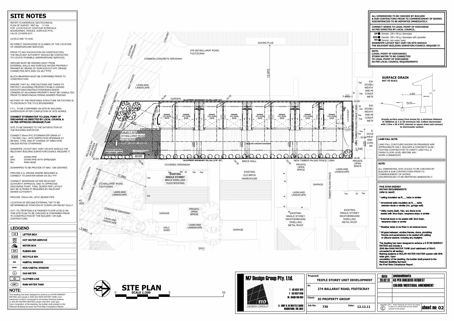
0 5 10SITE PLAN
SCALE 1:200
LAND FALL NOTE:LAND FALL NOTE:LAND FALL NOTE:LAND FALL NOTE:
LAND FALL CONTOURS SHOWN ON DRAWINGS AREAPPROXIMATE ONLY. BUILDER & CONCRETE SLAB /FOOTING CONTRACTOR TO VARIFY LAND FALL &FINISH FLOOR LEVEL BEFORE ANYWORK COMMENCES.
NOTE:NOTE:NOTE:NOTE:
ALL DIMENSIONS, SITE LEVLES TO BE CHECKED BYBUILDER & SUB-CONTRACTORS PRIOR TOCOMMENCEMENT OF WORKS.DISCREPENCIES TO BE REPORTED IMMEDIATELY.
FIVE STAR ENERGYFIVE STAR ENERGYFIVE STAR ENERGYFIVE STAR ENERGYRATING REQUIREMENTSRATING REQUIREMENTSRATING REQUIREMENTSRATING REQUIREMENTS(refer to report)(refer to report)(refer to report)(refer to report)
* ceiling insulation as R___ batts or similar* ceiling insulation as R___ batts or similar* ceiling insulation as R___ batts or similar* ceiling insulation as R___ batts or similar
* All external walls insulation as R___ batts* All external walls insulation as R___ batts* All external walls insulation as R___ batts* All external walls insulation as R___ batts between studs or similar (inc. garage wall) between studs or similar (inc. garage wall) between studs or similar (inc. garage wall) between studs or similar (inc. garage wall)
* Utility rooms (bath, l'dry, wc) doors to be* Utility rooms (bath, l'dry, wc) doors to be* Utility rooms (bath, l'dry, wc) doors to be* Utility rooms (bath, l'dry, wc) doors to be sealed with 3mm foam, neoprene strips or similar sealed with 3mm foam, neoprene strips or similar sealed with 3mm foam, neoprene strips or similar sealed with 3mm foam, neoprene strips or similar
* External doors to be sealed with 3mm foam,* External doors to be sealed with 3mm foam,* External doors to be sealed with 3mm foam,* External doors to be sealed with 3mm foam, neoprene strips or similar neoprene strips or similar neoprene strips or similar neoprene strips or similar
* Weather strips to be fitted to all external doors* Weather strips to be fitted to all external doors* Weather strips to be fitted to all external doors* Weather strips to be fitted to all external doors
* All gaps between; window frames, doors, plumbling* All gaps between; window frames, doors, plumbling* All gaps between; window frames, doors, plumbling* All gaps between; window frames, doors, plumbling fixtures and penetrations to be sealed with calking fixtures and penetrations to be sealed with calking fixtures and penetrations to be sealed with calking fixtures and penetrations to be sealed with calking or silicone sealant, includng any skylights or silicone sealant, includng any skylights or silicone sealant, includng any skylights or silicone sealant, includng any skylights
The dwelling has been designed to acheive a 5 STAR ENERGYThe dwelling has been designed to acheive a 5 STAR ENERGYThe dwelling has been designed to acheive a 5 STAR ENERGYThe dwelling has been designed to acheive a 5 STAR ENERGYRATING and include aRATING and include aRATING and include aRATING and include a2000 litre RAIN WATER TANK (roof catchment of 50m²)2000 litre RAIN WATER TANK (roof catchment of 50m²)2000 litre RAIN WATER TANK (roof catchment of 50m²)2000 litre RAIN WATER TANK (roof catchment of 50m²)connected to all sanitaryconnected to all sanitaryconnected to all sanitaryconnected to all sanitaryflushing systems or SOLAR WATER HEATER system with 60%flushing systems or SOLAR WATER HEATER system with 60%flushing systems or SOLAR WATER HEATER system with 60%flushing systems or SOLAR WATER HEATER system with 60%solar gain. Uponsolar gain. Uponsolar gain. Uponsolar gain. Uponcompletion of the dwelling, the builder shall present to thecompletion of the dwelling, the builder shall present to thecompletion of the dwelling, the builder shall present to thecompletion of the dwelling, the builder shall present to theRelevant Building SurveyorRelevant Building SurveyorRelevant Building SurveyorRelevant Building Surveyorthe First Rate Compliance Report.the First Rate Compliance Report.the First Rate Compliance Report.the First Rate Compliance Report.
LETTER BOXLETTER BOXLETTER BOXLETTER BOX
HOT WATER SERVICEHOT WATER SERVICEHOT WATER SERVICEHOT WATER SERVICE
NON HABITAL WINDOWNON HABITAL WINDOWNON HABITAL WINDOWNON HABITAL WINDOW
GAS METERGAS METERGAS METERGAS METER
CLOTHES LINECLOTHES LINECLOTHES LINECLOTHES LINE
RAIN WATER TANKRAIN WATER TANKRAIN WATER TANKRAIN WATER TANK
SITE NOTESREFER TO:HARDROCK GEOTECHNICALPLAN OF SURVEY REF No: 111154FOR LOCATION OF CONTOUR INTERVALS,BOUNDARIES, FENCES, SURFACE PITS,VALVE COVERS ECT.
LEVELS ARE TO AHD.
NO DIRECT KNOWLEDGE IS CLAIMED OF THE LOCATIONOF UNDERGROUND SERVICES.
PRIOR TO ANY EXCAVATION OR CONSTRUCTION,THE RELEVANT AUTHORITY SHOULD BE CONTACTEDTO LOCATE POSSIBLE UNDERGROUND SERVICES.
GROUND MUST BE GRADED AWAY FROMEXTERNAL WALLS AND SURFACE WATER PROPERLYDRAINED BY MEANS OF SURFACE/CUT-OFF DRAINSCONNECTED INTO SWD VIA SILT PITS
BLOCK BEARINGS MUST BE CONFIRMED PRIOR TOCONSTRUCTION.
ENSURE THAT ALL PRECAUTIONS ARE TAKEN TOPROTECT ADJOINING PROPERTY/PUBLIC DURINGEXCAVATION/CONSTRUCTION/DEMOLISHIONOWNERS OF ADJOINING PROPERTY MUST BE CONSULTEDPRIOR TO REMOVING/ALTERING SHARED FENCING
NO PART OF THE PROPOSED STRUCTURE OR FOOTING ISTO ENCROACH THE TITLE BOUNDARIES
F.F.L. TO BE CONFIRMED ON SITE BY BUILDINGSUPERVISOR AFTER COMPLETION OF SITE WORKS.
CONNECT STORMWATER TO LEGAL POINT OFCONNECT STORMWATER TO LEGAL POINT OFCONNECT STORMWATER TO LEGAL POINT OFCONNECT STORMWATER TO LEGAL POINT OFDISCHARGE AS DIRECTED BY LOCAL COUNCIL &DISCHARGE AS DIRECTED BY LOCAL COUNCIL &DISCHARGE AS DIRECTED BY LOCAL COUNCIL &DISCHARGE AS DIRECTED BY LOCAL COUNCIL &AS PER APPROVED DRAINAGE PLANAS PER APPROVED DRAINAGE PLANAS PER APPROVED DRAINAGE PLANAS PER APPROVED DRAINAGE PLAN
SITE TO BE DRAINED TO THE SATISFACTION OFTHE BUILDING SURVEYOR.
CONNECT 90mm PVC STORMWATER DRAIN AT1:100 MIN. FALL, WITH INSPECTION OPENINGS AT9M MAX. CTRS. AND AT CHANGE OF DIRECTIONUNLESS NOTED OTHERWISE.
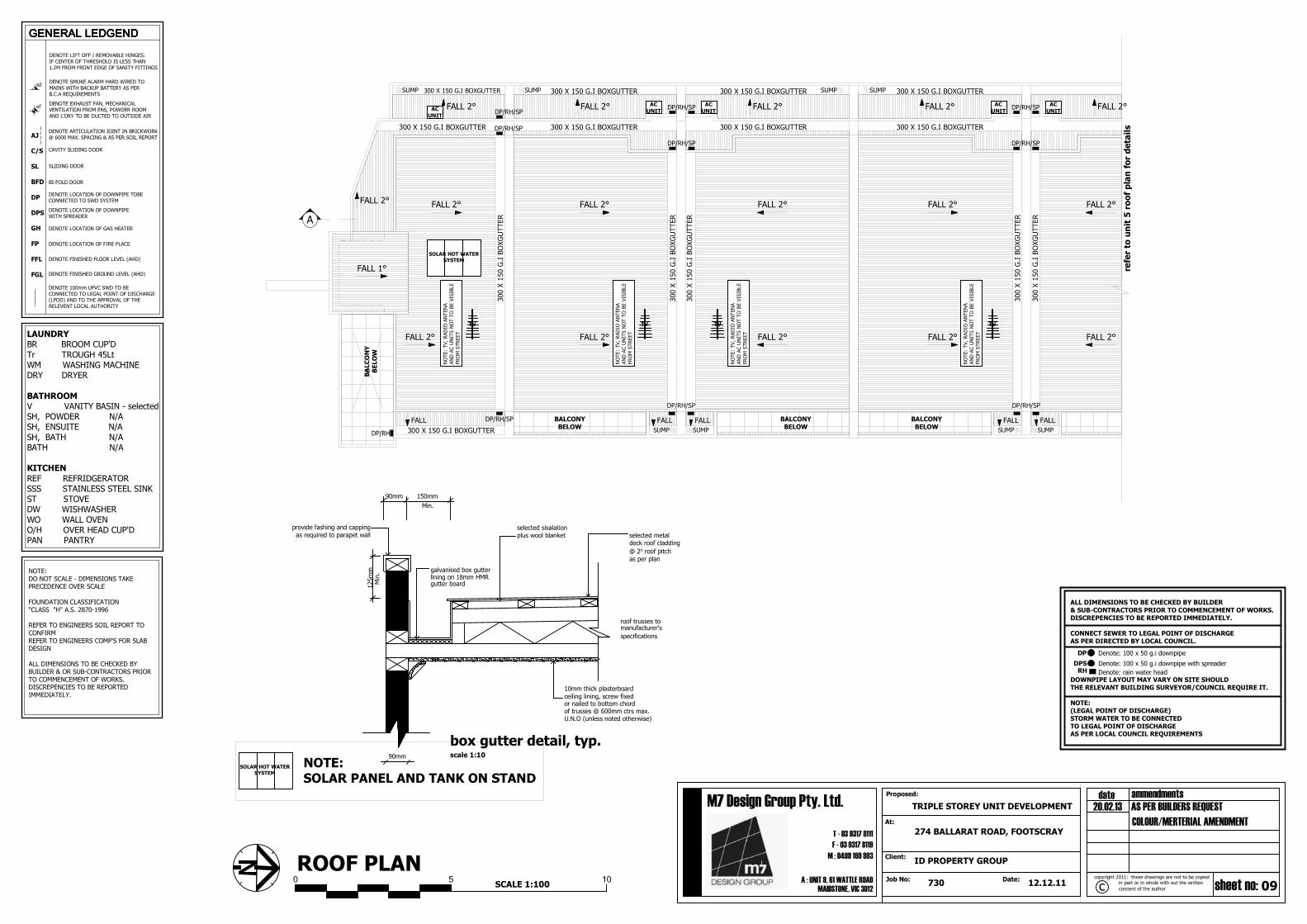
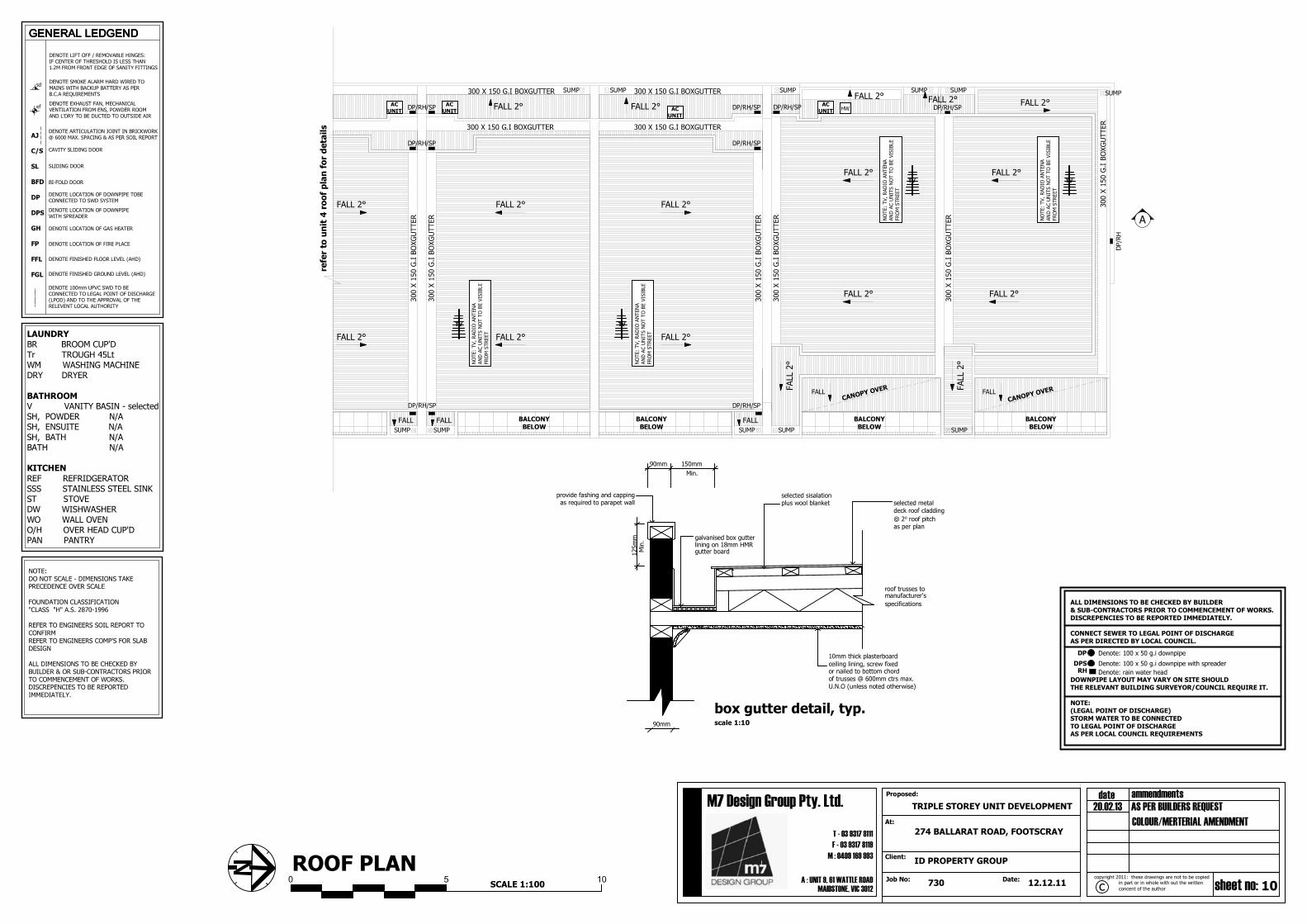
DOWNPIPE LAYOUT MAY VARY ON SITE SHOULD THERELEVANT BUILDING SURVEYOR/COUNCIL REQUIRE IT.
DP: DOWN PIPEDPS: DOWN PIPE WITH SPREADERRH: RAIN HEAD
DOWNPIPES TO BE PROVIDE AT MAX. 12M CENTRES
PROVIDE A.G. DRAINS WHERE REQUIRED &CONNECT TO S/WATER DRAIN VIA SILT PIT
CONNECT SEWERAGE AS PER RELEVANTAUTHORITY APPROVAL AND TO APPROVEDDISCHARGE POINT. FINAL SEWER PIPE LAYOUTMAY BE ALTERED IF REQUIRED BY RELEVANTSEWER AUTHORITY.
PROVIDE 100mm DIA. UPVC SEWER PIPE
LOCATION OF SECOND EXTERNAL TAP TO BEDETERMINED BY POSITION OF OVERFLOW RELIEF GULLY.
CUT / FIL PROPOSALS & FINISHED FLOOR LEVELS ONTHIS SITE PLAN TO BE CHECKED & CONFIRMED PRIORTO CONSTRUCTION BY THE BUILDER / OR SUB-CONTRACTORS.
RWT
NOTE:NOTE:NOTE:NOTE:
CL
BIN
R.BIN
MB
HWS
LB
G
HW
NHW
LEDGENDLEDGENDLEDGENDLEDGEND
The dwelling has been designed to acheive a 5 STAR ENERGYRATING and include a 2000 litre RAIN WATER TANK (roofcatchment of 50m²) connected to all sanitary flushing systemsor SOLAR WATER HEATER system with 60% solar gain.Upon completion of the dwelling, the builder shall present to theRelevant Building Surveyor the First Rate Compliance Report.
ALL DIMENSIONS TO BE CHECKED BY BUILDER& SUB-CONTRACTORS PRIOR TO COMMENCEMENT OF WORKS.DISCREPENCIES TO BE REPORTED IMMEDIATELY.
CONNECT SEWER TO LEGAL POINT OF DISCHARGEAS PER DIRECTED BY LOCAL COUNCIL.
DOWNPIPE LAYOUT MAY VARY ON SITE SHOULDTHE RELEVANT BUILDING SURVEYOR/COUNCIL REQUIRE IT.
NOTE:(LEGAL POINT OF DISCHARGE)STORM WATER TO BE CONNECTEDTO LEGAL POINT OF DISCHARGEAS PER LOCAL COUNCIL REQUIREMENTS
DP Denote: 100 x 50 g.i downpipe
DPS Denote: 100 x 50 g.i downpipe with spreaderRH Denote: rain water head
2,000
FALL 1:20DRAINNGL
DWELLING
Greade surface away from house for a minimum distanceof 2000mm at 1 in 20 minimum fall. Collect stormwater
with 115w x 95 d PVC channel or spoon drain and connect
galvanised box gutterlining on 18mm HMRgutter board
selected metaldeck roof cladding
box gutter detail, typ.
@ 2o roof pitchas per plan
roof trusses tomanufacturer's
specifications
10mm thick plasterboard
provide fashing and capping as required to parapet wall
selected sisalationplus wool blanket
11
M : 0409 169 993
Proposed: ammendmentsdate
concent of the author
in part or in whole with out the written sheet no:Date:
M7 Design Group Pty. Ltd.
cJob No:A : UNIT 9, 61 WATTLE ROAD
MAIDSTONE, VIC 3012
Client:
At:
F - 03 9317 8119
T - 03 9317 8111
copyright 2011: these drawings are not to be copied
730 12.12.11
274 BALLARAT ROAD, FOOTSCRAY
ID PROPERTY GROUP
TRIPLE STOREY UNIT DEVELOPMENT 20.02.13 AS PER BUILDERS REQUEST
COLOUR/MERTERIAL AMENDMENT
600 1,000
2,700
2,700
2,550
2,700
2,700
2,550
1,300
600
300
300 300
3,600
300
3,050
300
950
300
300
800
DOMESTIC NOTES1.The sight shall be adequately fenced off during construction to prevent public access:
2.No part of the building shall project beyond the boundary line, i.e.; including moulds,architectural features and the like;
3.The premises shall treat for termite protection using a chemical barrier in accordance
with AS3660.1-1995. Alternatively physical barriers may be adopted, such as ant caps orgranitgard. If adopting ant caps ensure there is sub floor clearance of
400mm;
4.Eaves within 900mm (But no closer than 450mm) of the boundary shall be
constructed using non combustible material;5.Eaves exposed to within 450mm of the boundary shall be protected by either a wing
wall or corbelled brickwork;
6.Rainwater heads, fascias, gutters, downpipes and the like within 450mm of the
boundary shall be constructed of non combustible materials;7.Openings in external walls within 900mm form the side facing the boundary require to
be protected, i.e.; windows shall be fixed, fire rated windows no less than -/60/-;
8.Open able windows within 1 metre of the finished floor level shall be restricted so that
the openings do not permit a 125mm sphere to pass through it, if the fall is greater than1 metre from the natural ground level;
9.The door to a fully enclosed sanitary compartment shall open outwards, slide or be
readily removable from the outside of the compartment, i.e.; removable hinges;10.The stumps are required to be brace in accordance with AS1684-1992, if the height of
the stump from natural ground level to the underside of the bearer excess the ratio of 15
times the width of the stump, i.e.; 100 x 100 stump has a maximum heigh
t of 1500mm;11.Vertical articulation joints must be provided in un-reinforced masonry walls except
walls built where the site soil classification is A or S. Articulation joints must have a width
not less than 10mm and be provided
a.In straight, continuous walls having no opening, at not more than 6m centres and notcloser than the height of the wall away from corners; and
b.Where the height of the wall changes by more than 20%, at the position of change in
height and
c.Where openings more than 900x900mm occur, at not more than 5m centres, andpositioned in line with one of the opening; and
d.Where walls change in thickness; and
e.At control or construction joints in footing slabs; andf.At junctions of walls construction of different masonry materials; and
g.At deep chases (rebates) for service pipes.
12.Sub floor ventilation shall be provided at a rate of 7300mm2/m, where in the minimum
sub-floor clearance is 150mm;13.Smoke detectors shall be a BRK 86 RAI 250v self-contained smoke alarm or the
equivalent to be connected to the consumer power mains in accordance with AS3786;
14.The wall surface of a shower enclosure with a preformed shower base shall be water
resistant to a height of 1.8m above the floor, with all junctions and floor to horizontalsurfaces completely waterproofed. The surface immediately adjacent or beh
ind a bath, basin or sink shall be water resistance to a height not less than 150mm
above the fixture with all junctions to horizontal surfaces completely waterproofed.
Furthermore, an enclosed shower with floor substrate;15.All glazing shall be accordance with AS 1288-1994 wherein, glazing within 500mm of
the floor level shall be 5mm thickened annealed, glazed doors and associates side
panels shall be 5.38mm laminated safety glass and bathroom windows within 1.5 ofthe the bath or 500mm from the shower enclosure shall be 3mm toughened safety glass;
16.A landing not less than 750mm wide shall be provided where the sill of a threshold of
a doorway opens on to a stair that provides a change in floor level or floor to ground level
greater than 3 risers or 570mm.17.The hearth shall extend 300mm beyond the front of the fireplace and 150mm beyond
each side of the opening. If the flooring is combustible the hearth must be situated
150mm above the floor;
18.Refer to Energy Rating Report for thermal insulation requirements19.Laundries, bathrooms, enquiries and powder rooms that are not naturally ventilated,
shall be provided with mechanical ventilation
20.The selection of gutters and downpipes shall be in accordance with AS3500.3.2,
wherein the spacing between downpipes must not be more than 12m and down pipesare also located within 1.2m of a valley or provision for overflow must be made;
21.The storm water discharge shall be connected to the existing legal point of discharge;
22.The ground beneath the suspended floor must be graded so that the area beneaththe building is above the adjacent external finished ground level and surface water is
prevented from ponding under the adjacent external finished ground level and sur
face water is prevented from ponding under the building. Alternatively, agricultural pipes
shall be provided beneath the building to drain ponding surface water. Surface watermust be diverted away from a slab-on-ground, so that the adjacent external
finished surface surrounding the slab must be drained to move surface water away from
the building and grede to give a slope of not less than 50mm over the first 1m from the
building;23.All footings shall extend 200mm beyond the angle of repose of all existing and not
more than 80% of the allotment can be covered by impermeable surfaces; and
24.Combustible roof lights, skylights or the like installed in a roof or part of a roof
required to have a non-combustible covering must have an aggregate area not more than 20% of the roof or part of the roof and be no less than 900mm from;
a.The allotment boundary other than the boundary adjoining a road alignment or other
public space: and
WINDOW LEGEND
NOTE:WINDOWS SIZES AND STYLES ARE NOMINAL ONLY & ARE MEASURED INTERNALLY
BETWEEN REVEALS. ACTUAL WINDOW SIZES MAY VARY DEPENDING ON THE
MANUFACTURERS STANDARDS. THE OWNER IS TO CONFIRM THE SIZES WITH THE
BUILDER'S WINDOW MANUFACTURER PRIOR TO COMMENCEMENT. WINDOWS TO BEFLASHED AS REQUIRED ALL WINDOWS ARE TO BE IN ACCORDANCE WITH A.S. 1288
F. DENOTES - Fixed Glazing
O. DENOTES - Openable GlazingSL. DENOTES - Sliding Door
OBS DENOTES - Obscured GlazingSG DENOTES - Safety Glass as per AS1288
CP DENOTES - All glazing to be pilkington comfort plus or similar
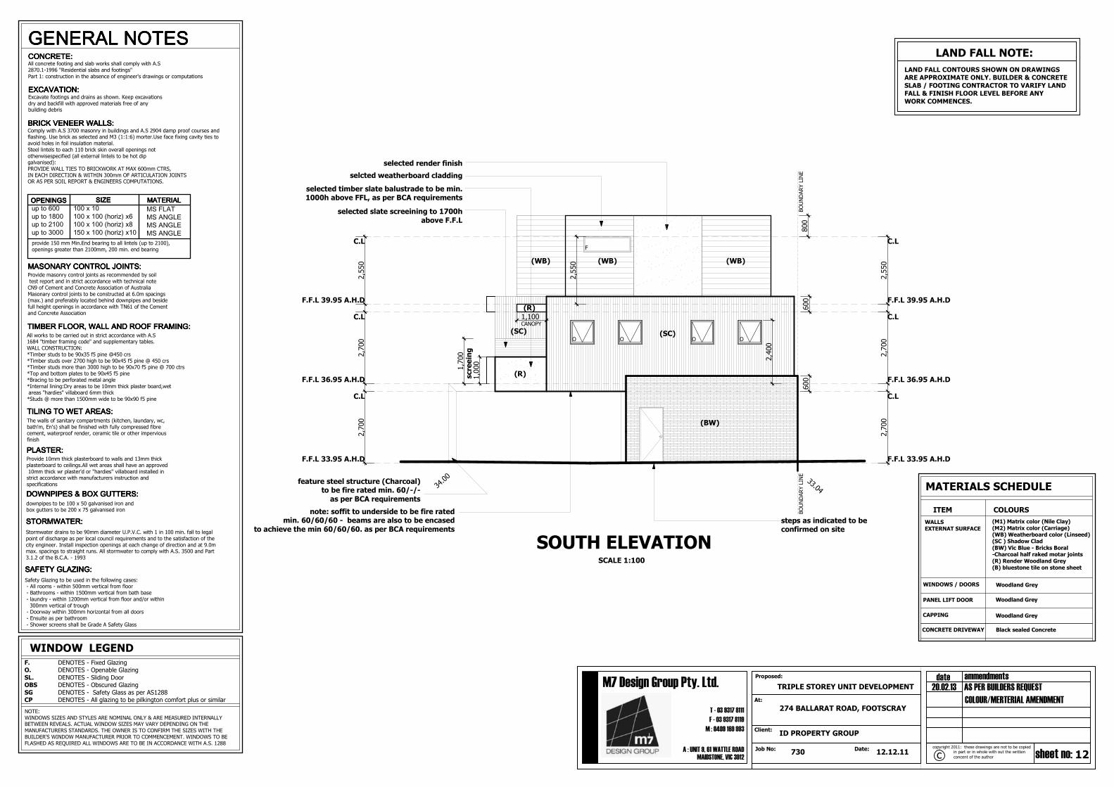
Black sealed Concrete
(M1) Matrix color (Nile Clay)(M2) Matrix color (Carriage)(WB) Weatherboard color (Linseed)(SC ) Shadow Clad(BW) Vic Blue - Bricks Boral-Charcoal half raked motar joints(R) Render Woodland Grey(B) bluestone tile on stone sheet
ITEM
Woodland Grey
MATERIALS SCHEDULE
COLOURS
CONCRETE DRIVEWAY
CAPPING
PANEL LIFT DOOR
WINDOWS / DOORS
WALLSEXTERNAT SURFACE
Woodland Grey
O O
BOUNDARY LINE
BOUNDARY LINE
F
FEATURE CANOPY
selected balustrade to be min. 1000habove FFL, as per BCA requirements
steps as indicated to be
confirmed on site
selected blockwork stackbond,
opeining
F.F.L 33.95 A.H.D
F.F.L 36.95 A.H.D
F.F.L 39.95 A.H.D
F.F.L 33.95 A.H.D
F.F.L 36.95 A.H.D
F.F.L 39.95 A.H.D
C.L
C.L
C.L C.L
C.L
C.L
NORTH ELEVATIONSCALE 1:100
position of sinage and mail boxes
LAND FALL CONTOURS SHOWN ON DRAWINGSARE APPROXIMATE ONLY. BUILDER & CONCRETE
SLAB / FOOTING CONTRACTOR TO VARIFY LANDFALL & FINISH FLOOR LEVEL BEFORE ANY
WORK COMMENCES.
LAND FALL NOTE:
33.70
33.84
(MI) (MI)
(MI)
(MI)
(WB)(WB)
(R)
(R)
(BW)
selected James Hardie matrix cladding(Nile Clay)
F
Woodland Grey
OOBS
S.G
note: soffit to underside to be fire ratedmin. 60/60/60 - beams are also to be encased
to achieve the min 60/60/60. as per BCA requirements
feature steel structure (Charcoal)to be fire rated min. 60/-/-as per BCA requirements
All concrete footing and slab works shall comply with A.S
2870.1-1996 "Residential slabs and footings"
Part 1: construction in the absence of engineer's drawings or computations
Safety Glazing to be used in the following cases: - All rooms - within 500mm vertical from floor
- Bathrooms - within 1500mm vertical from bath base
- laundry - within 1200mm vertical from floor and/or within
300mm vertical of trough - Doorway within 300mm horizontal from all doors
- Ensuite as per bathroom
- Shower screens shall be Grade A Safety Glass
Comply with A.S 3700 masonry in buildings and A.S 2904 damp proof courses andflashing. Use brick as selected and M3 (1:1:6) morter.Use face fixing cavity ties to
avoid holes in foil insulation material.
Steel lintels to each 110 brick skin overall openings not
otherwisespecified (all external lintels to be hot dipgalvanised):
PROVIDE WALL TIES TO BRICKWORK AT MAX 600mm CTRS,
IN EACH DIRECTION & WITHIN 300mm OF ARTICULATION JOINTSOR AS PER SOIL REPORT & ENGINEERS COMPUTATIONS.
Stormwater drains to be 90mm diameter U.P.V.C. with 1 in 100 min. fall to legal
point of discharge as per local council requirements and to the satisfaction of the
city engineer. Install inspection openings at each change of direction and at 9.0mmax. spacings to straight runs. All stormwater to comply with A.S. 3500 and Part
3.1.2 of the B.C.A. - 1993
EXCAVATION:EXCAVATION:EXCAVATION:EXCAVATION:Excavate footings and drains as shown. Keep excavations
dry and backfill with approved materials free of anybuilding debris
LAND FALL CONTOURS SHOWN ON DRAWINGSARE APPROXIMATE ONLY. BUILDER & CONCRETE
SLAB / FOOTING CONTRACTOR TO VARIFY LANDFALL & FINISH FLOOR LEVEL BEFORE ANY
WINDOWS SIZES AND STYLES ARE NOMINAL ONLY & ARE MEASURED INTERNALLYBETWEEN REVEALS. ACTUAL WINDOW SIZES MAY VARY DEPENDING ON THE
MANUFACTURERS STANDARDS. THE OWNER IS TO CONFIRM THE SIZES WITH THE
BUILDER'S WINDOW MANUFACTURER PRIOR TO COMMENCEMENT. WINDOWS TO BE
FLASHED AS REQUIRED ALL WINDOWS ARE TO BE IN ACCORDANCE WITH A.S. 1288
F. DENOTES - Fixed GlazingO. DENOTES - Openable Glazing
SL. DENOTES - Sliding DoorOBS DENOTES - Obscured Glazing
SG DENOTES - Safety Glass as per AS1288CP DENOTES - All glazing to be pilkington comfort plus or similar
steps as indicated to beconfirmed on site
F
screeing
selected slate screeining to 1700h
above F.F.L
F.F.L 33.95 A.H.D
F.F.L 36.95 A.H.D
F.F.L 39.95 A.H.D
F.F.L 33.95 A.H.D
F.F.L 36.95 A.H.D
F.F.L 39.95 A.H.D
C.L
C.L
C.LC.L
C.L
C.L
BOUNDARY LINE
BOUNDARY LINE
SOUTH ELEVATIONSCALE 1:100
selected timber slate balustrade to be min.1000h above FFL, as per BCA requirements
33.0434.00
O O O O
CANOPY
(SC)
(BW)
Black sealed Concrete
ITEM
Woodland Grey
MATERIALS SCHEDULE
COLOURS
CONCRETE DRIVEWAY
CAPPING
PANEL LIFT DOOR
WINDOWS / DOORS
WALLSEXTERNAT SURFACE
Woodland Grey
Woodland Grey
(R)
feature steel structure (Charcoal)to be fire rated min. 60/-/-
as per BCA requirements
note: soffit to underside to be fire ratedmin. 60/60/60 - beams are also to be encased
to achieve the min 60/60/60. as per BCA requirements
selcted weatherboard cladding
selected render finish
(WB)(WB) (WB)
(R)
(SC)
(M1) Matrix color (Nile Clay)(M2) Matrix color (Carriage)(WB) Weatherboard color (Linseed)(SC ) Shadow Clad(BW) Vic Blue - Bricks Boral-Charcoal half raked motar joints(R) Render Woodland Grey(B) bluestone tile on stone sheet
13
M : 0409 169 993
Proposed: ammendmentsdate
concent of the author
in part or in whole with out the written sheet no:Date:
M7 Design Group Pty. Ltd.
cJob No:A : UNIT 9, 61 WATTLE ROAD
MAIDSTONE, VIC 3012
Client:
At:
F - 03 9317 8119
T - 03 9317 8111
copyright 2011: these drawings are not to be copied
730 12.12.11
274 BALLARAT ROAD, FOOTSCRAY
ID PROPERTY GROUP
TRIPLE STOREY UNIT DEVELOPMENT 20.02.13 AS PER BUILDERS REQUEST
COLOUR/MERTERIAL AMENDMENT
DOMESTIC NOTES1.The sight shall be adequately fenced off during construction to prevent public access:
2.No part of the building shall project beyond the boundary line, i.e.; including moulds,architectural features and the like;
3.The premises shall treat for termite protection using a chemical barrier in accordance
with AS3660.1-1995. Alternatively physical barriers may be adopted, such as ant caps orgranitgard. If adopting ant caps ensure there is sub floor clearance of
400mm;
4.Eaves within 900mm (But no closer than 450mm) of the boundary shall beconstructed using non combustible material;
5.Eaves exposed to within 450mm of the boundary shall be protected by either a wing
wall or corbelled brickwork;6.Rainwater heads, fascias, gutters, downpipes and the like within 450mm of the
boundary shall be constructed of non combustible materials;
7.Openings in external walls within 900mm form the side facing the boundary require to be protected, i.e.; windows shall be fixed, fire rated windows no less than -/60/-;
8.Open able windows within 1 metre of the finished floor level shall be restricted so that the openings do not permit a 125mm sphere to pass through it, if the fall is greater than
1 metre from the natural ground level;
9.The door to a fully enclosed sanitary compartment shall open outwards, slide or bereadily removable from the outside of the compartment, i.e.; removable hinges;
10.The stumps are required to be brace in accordance with AS1684-1992, if the height of
the stump from natural ground level to the underside of the bearer excess the ratio of 15times the width of the stump, i.e.; 100 x 100 stump has a maximum heigh
t of 1500mm;
11.Vertical articulation joints must be provided in un-reinforced masonry walls exceptwalls built where the site soil classification is A or S. Articulation joints must have a width
not less than 10mm and be provideda.In straight, continuous walls having no opening, at not more than 6m centres and not
closer than the height of the wall away from corners; and
b.Where the height of the wall changes by more than 20%, at the position of change inheight and
c.Where openings more than 900x900mm occur, at not more than 5m centres, and
positioned in line with one of the opening; andd.Where walls change in thickness; and
e.At control or construction joints in footing slabs; and
f.At junctions of walls construction of different masonry materials; andg.At deep chases (rebates) for service pipes.
12.Sub floor ventilation shall be provided at a rate of 7300mm2/m, where in the minimum
sub-floor clearance is 150mm;13.Smoke detectors shall be a BRK 86 RAI 250v self-contained smoke alarm or the
equivalent to be connected to the consumer power mains in accordance with AS3786;14.The wall surface of a shower enclosure with a preformed shower base shall be water
resistant to a height of 1.8m above the floor, with all junctions and floor to horizontal
surfaces completely waterproofed. The surface immediately adjacent or behind a bath, basin or sink shall be water resistance to a height not less than 150mm
above the fixture with all junctions to horizontal surfaces completely waterproofed.
Furthermore, an enclosed shower with floor substrate;15.All glazing shall be accordance with AS 1288-1994 wherein, glazing within 500mm of
the floor level shall be 5mm thickened annealed, glazed doors and associates side
panels shall be 5.38mm laminated safety glass and bathroom windows within 1.5 ofthe the bath or 500mm from the shower enclosure shall be 3mm toughened safety glass;
16.A landing not less than 750mm wide shall be provided where the sill of a threshold of
a doorway opens on to a stair that provides a change in floor level or floor to ground levelgreater than 3 risers or 570mm.
17.The hearth shall extend 300mm beyond the front of the fireplace and 150mm beyondeach side of the opening. If the flooring is combustible the hearth must be situated
150mm above the floor;
18.Refer to Energy Rating Report for thermal insulation requirements19.Laundries, bathrooms, enquiries and powder rooms that are not naturally ventilated,
shall be provided with mechanical ventilation
20.The selection of gutters and downpipes shall be in accordance with AS3500.3.2,wherein the spacing between downpipes must not be more than 12m and down pipes
are also located within 1.2m of a valley or provision for overflow must be made;
21.The storm water discharge shall be connected to the existing legal point of discharge;22.The ground beneath the suspended floor must be graded so that the area beneath
the building is above the adjacent external finished ground level and surface water is
prevented from ponding under the adjacent external finished ground level and surface water is prevented from ponding under the building. Alternatively, agricultural pipes
shall be provided beneath the building to drain ponding surface water. Surface watermust be diverted away from a slab-on-ground, so that the adjacent external
finished surface surrounding the slab must be drained to move surface water away from
the building and grede to give a slope of not less than 50mm over the first 1m from thebuilding;
23.All footings shall extend 200mm beyond the angle of repose of all existing and not
more than 80% of the allotment can be covered by impermeable surfaces; and24.Combustible roof lights, skylights or the like installed in a roof or part of a roof
required to have a non-combustible covering must have an aggregate area not more than
20% of the roof or part of the roof and be no less than 900mm from;a.The allotment boundary other than the boundary adjoining a road alignment or other
public space: and
WINDOW LEGEND
NOTE:
WINDOWS SIZES AND STYLES ARE NOMINAL ONLY & ARE MEASURED INTERNALLY
BETWEEN REVEALS. ACTUAL WINDOW SIZES MAY VARY DEPENDING ON THEMANUFACTURERS STANDARDS. THE OWNER IS TO CONFIRM THE SIZES WITH THE
BUILDER'S WINDOW MANUFACTURER PRIOR TO COMMENCEMENT. WINDOWS TO BE
FLASHED AS REQUIRED ALL WINDOWS ARE TO BE IN ACCORDANCE WITH A.S. 1288
F. DENOTES - Fixed Glazing
O. DENOTES - Openable Glazing
SL. DENOTES - Sliding Door
OBS DENOTES - Obscured Glazing
SG DENOTES - Safety Glass as per AS1288
CP DENOTES - All glazing to be pilkington comfort plus or similar
2,700
2,700
2,550
300
800
1,300
1,000
600
1,700
1,000
1,700
1,000
1,700
1,000
3,050
2,800
F.F.L 33.95 A.H.D
F.F.L 36.95 A.H.D
F.F.L 39.95 A.H.D
C.L
C.L
C.L
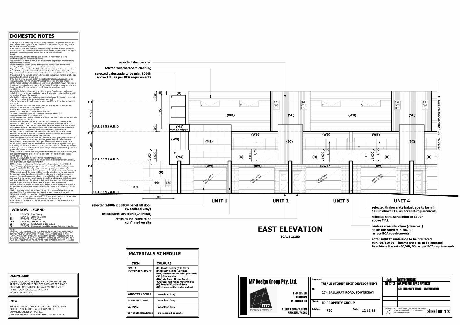
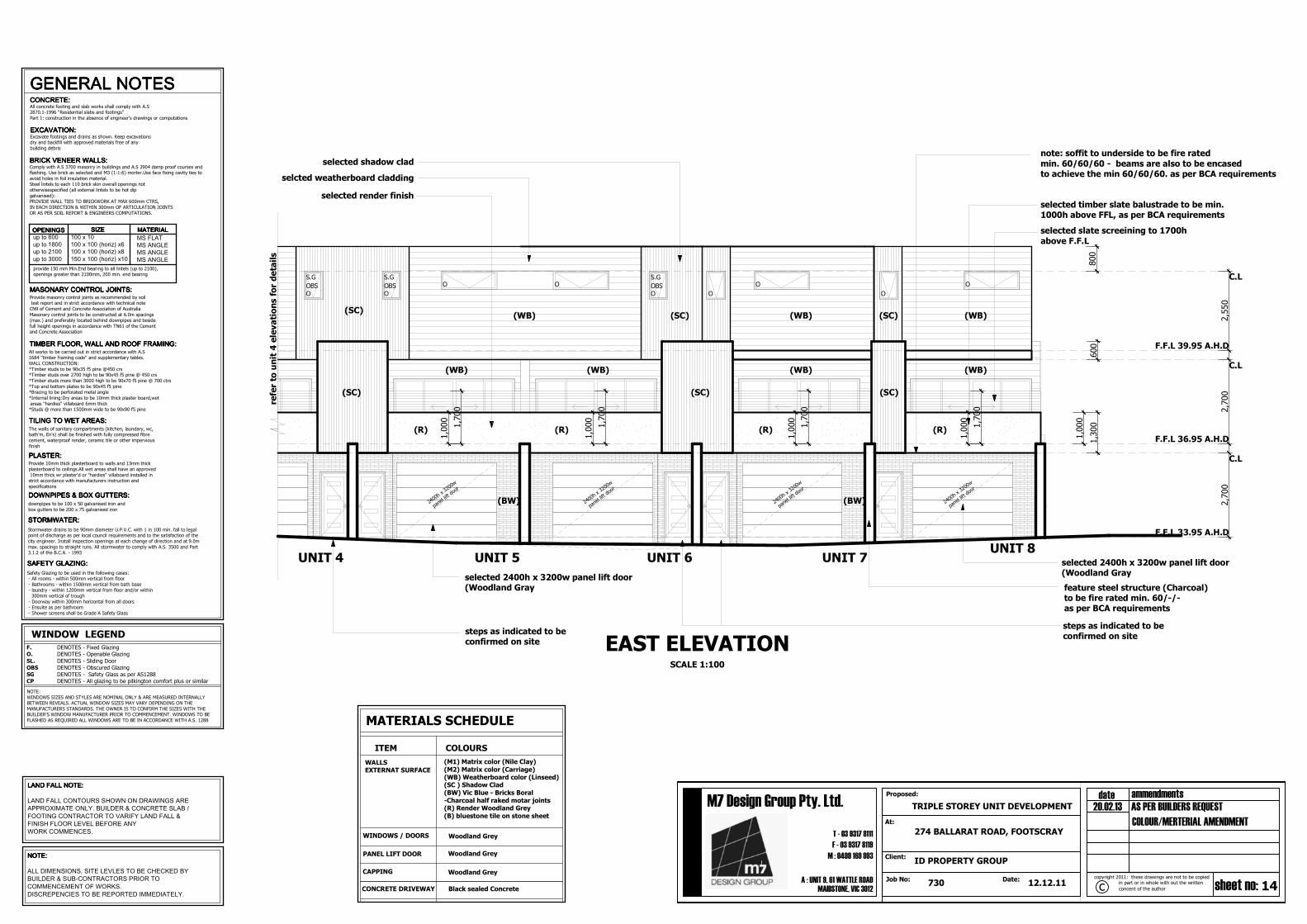
EAST ELEVATIONSCALE 1:100
UNIT 1 UNIT 2 UNIT 3 UNIT 4
selected balustrade to be min. 1000habove FFL, as per BCA requirements
steps as indicated to be
confirmed on site
O O
O O
O O
O O
F
F
selected 2400h x 3000w panel lift door(Woodland Gray)
refer to unit 5 elevations for details
selected slate screeining to 1700h
above F.F.L
selected timber slate balustrade to be min.1000h above FFL, as per BCA requirements
2400h x 3000w
panel lift door
2400h x 3200w
panel lift door
2400h x 3200w
panel lift door
2400h x 3200w
panel lift door
FEATURE CANOPY
LAND FALL NOTE:LAND FALL NOTE:LAND FALL NOTE:LAND FALL NOTE:
LAND FALL CONTOURS SHOWN ON DRAWINGS AREAPPROXIMATE ONLY. BUILDER & CONCRETE SLAB /FOOTING CONTRACTOR TO VARIFY LAND FALL &FINISH FLOOR LEVEL BEFORE ANYWORK COMMENCES.
NOTE:NOTE:NOTE:NOTE:
ALL DIMENSIONS, SITE LEVLES TO BE CHECKED BYBUILDER & SUB-CONTRACTORS PRIOR TOCOMMENCEMENT OF WORKS.DISCREPENCIES TO BE REPORTED IMMEDIATELY.
OBS OBS
S.G S.G
OBS
S.G
OBS
S.G
BINS
L/BM/B
featue steel structure (Charcoal)
(BW) (BW) (BW) (BW)
(M2) (SC) (SC)
(M1)
(M1)
(WB) (WB)
(WB) (WB) (WB)
(SC)(SC)
(R)
F
Black sealed Concrete
ITEM
Woodland Grey
MATERIALS SCHEDULE
COLOURS
CONCRETE DRIVEWAY
CAPPING
PANEL LIFT DOOR
WINDOWS / DOORS
WALLSEXTERNAT SURFACE
Woodland Grey
Woodland Grey
(R) (R) (R) (R)
(WB)
feature steel structure (Charcoal)to be fire rated min. 60/-/-as per BCA requirements
note: soffit to underside to be fire ratedmin. 60/60/60 - beams are also to be encasedto achieve the min 60/60/60. as per BCA requirements
(B)
selcted weatherboard cladding
selected shadow clad
(M1) Matrix color (Nile Clay)(M2) Matrix color (Carriage)(WB) Weatherboard color (Linseed)(SC ) Shadow Clad(BW) Vic Blue - Bricks Boral-Charcoal half raked motar joints(R) Render Woodland Grey(B) bluestone tile on stone sheet
14
M : 0409 169 993
Proposed: ammendmentsdate
concent of the author
in part or in whole with out the written sheet no:Date:
M7 Design Group Pty. Ltd.
cJob No:A : UNIT 9, 61 WATTLE ROAD
MAIDSTONE, VIC 3012
Client:
At:
F - 03 9317 8119
T - 03 9317 8111
copyright 2011: these drawings are not to be copied
730 12.12.11
274 BALLARAT ROAD, FOOTSCRAY
ID PROPERTY GROUP
TRIPLE STOREY UNIT DEVELOPMENT 20.02.13 AS PER BUILDERS REQUEST
COLOUR/MERTERIAL AMENDMENT
WINDOW LEGEND
GENERAL NOTESGENERAL NOTESGENERAL NOTESGENERAL NOTES
All concrete footing and slab works shall comply with A.S2870.1-1996 "Residential slabs and footings"
Part 1: construction in the absence of engineer's drawings or computations
Safety Glazing to be used in the following cases: - All rooms - within 500mm vertical from floor
- Bathrooms - within 1500mm vertical from bath base - laundry - within 1200mm vertical from floor and/or within
300mm vertical of trough
- Doorway within 300mm horizontal from all doors - Ensuite as per bathroom
- Shower screens shall be Grade A Safety Glass
Comply with A.S 3700 masonry in buildings and A.S 2904 damp proof courses andflashing. Use brick as selected and M3 (1:1:6) morter.Use face fixing cavity ties to
avoid holes in foil insulation material.Steel lintels to each 110 brick skin overall openings not
otherwisespecified (all external lintels to be hot dip
galvanised):PROVIDE WALL TIES TO BRICKWORK AT MAX 600mm CTRS,
IN EACH DIRECTION & WITHIN 300mm OF ARTICULATION JOINTS
OR AS PER SOIL REPORT & ENGINEERS COMPUTATIONS.
Stormwater drains to be 90mm diameter U.P.V.C. with 1 in 100 min. fall to legalpoint of discharge as per local council requirements and to the satisfaction of the
city engineer. Install inspection openings at each change of direction and at 9.0m
max. spacings to straight runs. All stormwater to comply with A.S. 3500 and Part3.1.2 of the B.C.A. - 1993
EXCAVATION:EXCAVATION:EXCAVATION:EXCAVATION:Excavate footings and drains as shown. Keep excavationsdry and backfill with approved materials free of any
MATERIALMATERIALMATERIALMATERIALup to 600up to 1800up to 2100up to 3000
MASONARY CONTROL JOINTS:MASONARY CONTROL JOINTS:MASONARY CONTROL JOINTS:MASONARY CONTROL JOINTS:Provide masonry control joints as recommended by soil test report and in strict accordance with technical note
CN9 of Cement and Concrete Association of Australia
Masonary control joints to be constructed at 6.0m spacings(max.) and preferably located behind downpipes and beside
full height openings in accordance with TN61 of the Cementand Concrete Association
All works to be carried out in strict accordance with A.S1684 "timber framing code" and supplementary tables.
WALL CONSTRUCTION:
*Timber studs to be 90x35 f5 pine @450 crs*Timber studs over 2700 high to be 90x45 f5 pine @ 450 crs
*Timber studs more than 3000 high to be 90x70 f5 pine @ 700 ctrs
*Top and bottom plates to be 90x45 f5 pine*Bracing to be perforated metal angle
*Internal lining:Dry areas to be 10mm thick plaster board,wet
areas "hardies" villaboard 6mm thick*Studs @ more than 1500mm wide to be 90x90 f5 pine
TIMBER FLOOR, WALL AND ROOF TIMBER FLOOR, WALL AND ROOF TIMBER FLOOR, WALL AND ROOF TIMBER FLOOR, WALL AND ROOF FRAMING:FRAMING:FRAMING:FRAMING:
The walls of sanitary compartments (kitchen, laundary, wc,bath'm, En's) shall be finished with fully compressed fibre
cement, waterproof render, ceramic tile or other impervious
finish
TILING TO WET AREAS:TILING TO WET AREAS:TILING TO WET AREAS:TILING TO WET AREAS:
WINDOWS SIZES AND STYLES ARE NOMINAL ONLY & ARE MEASURED INTERNALLYBETWEEN REVEALS. ACTUAL WINDOW SIZES MAY VARY DEPENDING ON THE
MANUFACTURERS STANDARDS. THE OWNER IS TO CONFIRM THE SIZES WITH THEBUILDER'S WINDOW MANUFACTURER PRIOR TO COMMENCEMENT. WINDOWS TO BE
FLASHED AS REQUIRED ALL WINDOWS ARE TO BE IN ACCORDANCE WITH A.S. 1288
F. DENOTES - Fixed Glazing
O. DENOTES - Openable Glazing
SL. DENOTES - Sliding Door
OBS DENOTES - Obscured Glazing
SG DENOTES - Safety Glass as per AS1288
CP DENOTES - All glazing to be pilkington comfort plus or similar
2,700
2,700
2,550
1,300
1,000
600
1,000
1,700
1,000
1,700
1,000
1,700
1,000
1,700
800
F.F.L 33.95 A.H.D
F.F.L 36.95 A.H.D
F.F.L 39.95 A.H.D
C.L
C.L
C.L
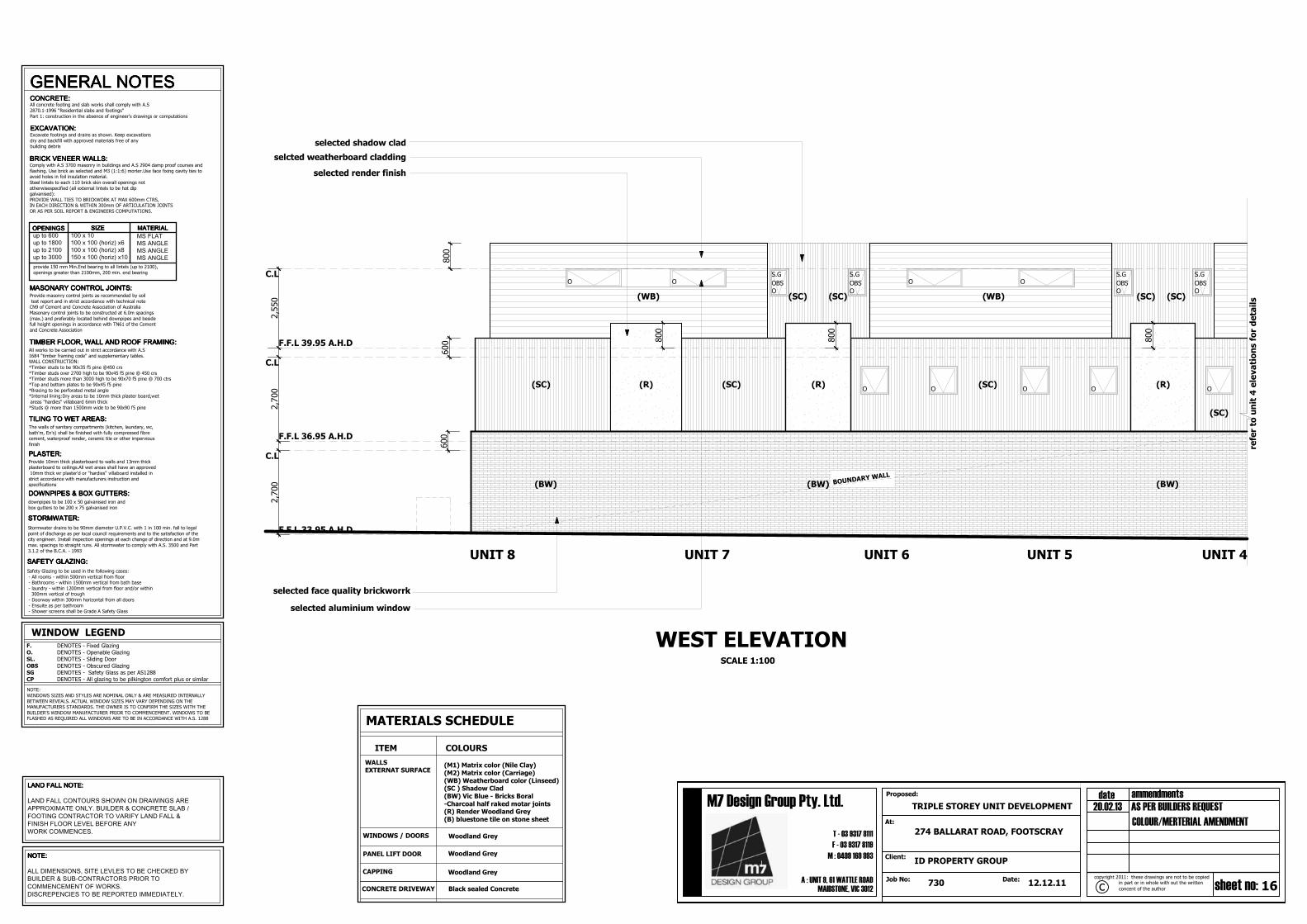
EAST ELEVATIONSCALE 1:100
UNIT 4 UNIT 5 UNIT 6 UNIT 7UNIT 8
steps as indicated to beconfirmed on site
O O
O O
O O
O
O
O
steps as indicated to beconfirmed on site
refer to unit 4 elevations for details
2400h x 3200w
panel lift door
2400h x 3200w
panel lift door
2400h x 3200w
panel lift door
2400h x 3200w
panel lift door
selected slate screeining to 1700h
above F.F.L
selected timber slate balustrade to be min.1000h above FFL, as per BCA requirements
LAND FALL NOTE:LAND FALL NOTE:LAND FALL NOTE:LAND FALL NOTE:
LAND FALL CONTOURS SHOWN ON DRAWINGS AREAPPROXIMATE ONLY. BUILDER & CONCRETE SLAB /FOOTING CONTRACTOR TO VARIFY LAND FALL &FINISH FLOOR LEVEL BEFORE ANYWORK COMMENCES.
NOTE:NOTE:NOTE:NOTE:
ALL DIMENSIONS, SITE LEVLES TO BE CHECKED BYBUILDER & SUB-CONTRACTORS PRIOR TOCOMMENCEMENT OF WORKS.DISCREPENCIES TO BE REPORTED IMMEDIATELY.
OBS
S.G
OBS
S.G
OBS
S.G
(SC)
(WB) (WB) (WB)
(WB)(WB)(WB)
(SC) (SC)
selected 2400h x 3200w panel lift door(Woodland Gray
selected 2400h x 3200w panel lift door(Woodland Gray
(WB)
Black sealed Concrete
ITEM
Woodland Grey
MATERIALS SCHEDULE
COLOURS
CONCRETE DRIVEWAY
CAPPING
PANEL LIFT DOOR
WINDOWS / DOORS
WALLSEXTERNAT SURFACE
Woodland Grey
Woodland Grey
(SC)(SC) (SC)
(R)(R) (R) (R)
feature steel structure (Charcoal)to be fire rated min. 60/-/-as per BCA requirements
note: soffit to underside to be fire rated
min. 60/60/60 - beams are also to be encasedto achieve the min 60/60/60. as per BCA requirements
(BW) (BW)
selcted weatherboard cladding
selected render finish
selected shadow clad
(M1) Matrix color (Nile Clay)(M2) Matrix color (Carriage)(WB) Weatherboard color (Linseed)(SC ) Shadow Clad(BW) Vic Blue - Bricks Boral-Charcoal half raked motar joints(R) Render Woodland Grey(B) bluestone tile on stone sheet
15
M : 0409 169 993
Proposed: ammendmentsdate
concent of the author
in part or in whole with out the written sheet no:Date:
M7 Design Group Pty. Ltd.
cJob No:A : UNIT 9, 61 WATTLE ROAD
MAIDSTONE, VIC 3012
Client:
At:
F - 03 9317 8119
T - 03 9317 8111
copyright 2011: these drawings are not to be copied
730 12.12.11
274 BALLARAT ROAD, FOOTSCRAY
ID PROPERTY GROUP
TRIPLE STOREY UNIT DEVELOPMENT 20.02.13 AS PER BUILDERS REQUEST
COLOUR/MERTERIAL AMENDMENT
DOMESTIC NOTES1.The sight shall be adequately fenced off during construction to prevent public access:
2.No part of the building shall project beyond the boundary line, i.e.; including moulds,architectural features and the like;
3.The premises shall treat for termite protection using a chemical barrier in accordance
with AS3660.1-1995. Alternatively physical barriers may be adopted, such as ant caps orgranitgard. If adopting ant caps ensure there is sub floor clearance of
400mm;
4.Eaves within 900mm (But no closer than 450mm) of the boundary shall beconstructed using non combustible material;
5.Eaves exposed to within 450mm of the boundary shall be protected by either a wing
wall or corbelled brickwork;6.Rainwater heads, fascias, gutters, downpipes and the like within 450mm of the
boundary shall be constructed of non combustible materials;
7.Openings in external walls within 900mm form the side facing the boundary require to be protected, i.e.; windows shall be fixed, fire rated windows no less than -/60/-;
8.Open able windows within 1 metre of the finished floor level shall be restricted so that the openings do not permit a 125mm sphere to pass through it, if the fall is greater than
1 metre from the natural ground level;
9.The door to a fully enclosed sanitary compartment shall open outwards, slide or bereadily removable from the outside of the compartment, i.e.; removable hinges;
10.The stumps are required to be brace in accordance with AS1684-1992, if the height of
the stump from natural ground level to the underside of the bearer excess the ratio of 15times the width of the stump, i.e.; 100 x 100 stump has a maximum heigh
t of 1500mm;
11.Vertical articulation joints must be provided in un-reinforced masonry walls exceptwalls built where the site soil classification is A or S. Articulation joints must have a width
not less than 10mm and be provided
a.In straight, continuous walls having no opening, at not more than 6m centres and notcloser than the height of the wall away from corners; and
b.Where the height of the wall changes by more than 20%, at the position of change inheight and
c.Where openings more than 900x900mm occur, at not more than 5m centres, and
positioned in line with one of the opening; andd.Where walls change in thickness; and
e.At control or construction joints in footing slabs; and
f.At junctions of walls construction of different masonry materials; andg.At deep chases (rebates) for service pipes.
12.Sub floor ventilation shall be provided at a rate of 7300mm2/m, where in the minimum
sub-floor clearance is 150mm;13.Smoke detectors shall be a BRK 86 RAI 250v self-contained smoke alarm or the
equivalent to be connected to the consumer power mains in accordance with AS3786;14.The wall surface of a shower enclosure with a preformed shower base shall be water
resistant to a height of 1.8m above the floor, with all junctions and floor to horizontal
surfaces completely waterproofed. The surface immediately adjacent or behind a bath, basin or sink shall be water resistance to a height not less than 150mm
above the fixture with all junctions to horizontal surfaces completely waterproofed.
Furthermore, an enclosed shower with floor substrate;15.All glazing shall be accordance with AS 1288-1994 wherein, glazing within 500mm of
the floor level shall be 5mm thickened annealed, glazed doors and associates side
panels shall be 5.38mm laminated safety glass and bathroom windows within 1.5 ofthe the bath or 500mm from the shower enclosure shall be 3mm toughened safety glass;
16.A landing not less than 750mm wide shall be provided where the sill of a threshold of
a doorway opens on to a stair that provides a change in floor level or floor to ground levelgreater than 3 risers or 570mm.
17.The hearth shall extend 300mm beyond the front of the fireplace and 150mm beyondeach side of the opening. If the flooring is combustible the hearth must be situated
150mm above the floor;
18.Refer to Energy Rating Report for thermal insulation requirements19.Laundries, bathrooms, enquiries and powder rooms that are not naturally ventilated,
shall be provided with mechanical ventilation
20.The selection of gutters and downpipes shall be in accordance with AS3500.3.2,wherein the spacing between downpipes must not be more than 12m and down pipes
are also located within 1.2m of a valley or provision for overflow must be made;
21.The storm water discharge shall be connected to the existing legal point of discharge;22.The ground beneath the suspended floor must be graded so that the area beneath
the building is above the adjacent external finished ground level and surface water is
prevented from ponding under the adjacent external finished ground level and surface water is prevented from ponding under the building. Alternatively, agricultural pipes
shall be provided beneath the building to drain ponding surface water. Surface watermust be diverted away from a slab-on-ground, so that the adjacent external
finished surface surrounding the slab must be drained to move surface water away from
the building and grede to give a slope of not less than 50mm over the first 1m from thebuilding;
23.All footings shall extend 200mm beyond the angle of repose of all existing and not
more than 80% of the allotment can be covered by impermeable surfaces; and24.Combustible roof lights, skylights or the like installed in a roof or part of a roof
required to have a non-combustible covering must have an aggregate area not more than
20% of the roof or part of the roof and be no less than 900mm from;a.The allotment boundary other than the boundary adjoining a road alignment or other
public space: and
WINDOW LEGEND
NOTE:
WINDOWS SIZES AND STYLES ARE NOMINAL ONLY & ARE MEASURED INTERNALLY
BETWEEN REVEALS. ACTUAL WINDOW SIZES MAY VARY DEPENDING ON THEMANUFACTURERS STANDARDS. THE OWNER IS TO CONFIRM THE SIZES WITH THE
BUILDER'S WINDOW MANUFACTURER PRIOR TO COMMENCEMENT. WINDOWS TO BE
FLASHED AS REQUIRED ALL WINDOWS ARE TO BE IN ACCORDANCE WITH A.S. 1288
F. DENOTES - Fixed Glazing
O. DENOTES - Openable Glazing
SL. DENOTES - Sliding Door
OBS DENOTES - Obscured Glazing
SG DENOTES - Safety Glass as per AS1288
CP DENOTES - All glazing to be pilkington comfort plus or similar
2,700
2,700
2,550
300
3,050
300
600
2,400
2,400
2,400
800
F.F.L 33.95 A.H.D
F.F.L 36.95 A.H.D
F.F.L 39.95 A.H.D
C.L
C.L
C.L
O O O
O
O
O
O O
O O
O
O O
O
O
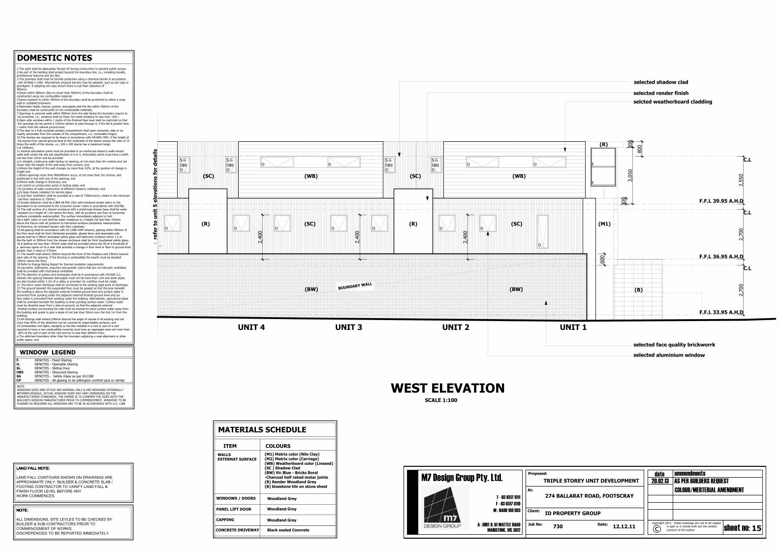
UNIT 4 UNIT 3 UNIT 2 UNIT 1
SCALE 1:100
refer to unit 5 elevations for details
LAND FALL NOTE:LAND FALL NOTE:LAND FALL NOTE:LAND FALL NOTE:
LAND FALL CONTOURS SHOWN ON DRAWINGS AREAPPROXIMATE ONLY. BUILDER & CONCRETE SLAB /FOOTING CONTRACTOR TO VARIFY LAND FALL &FINISH FLOOR LEVEL BEFORE ANYWORK COMMENCES.
NOTE:NOTE:NOTE:NOTE:
ALL DIMENSIONS, SITE LEVLES TO BE CHECKED BYBUILDER & SUB-CONTRACTORS PRIOR TOCOMMENCEMENT OF WORKS.DISCREPENCIES TO BE REPORTED IMMEDIATELY.
OBS
S.G
OBS
S.G
OOBS
S.G
OBS
S.G
BOUNDARY W
ALL
(R) (R)(SC) (SC)
(BW)(BW)
(WB) (WB)(SC) (SC)
(R)
F
F
(M1)
Black sealed Concrete
ITEM
Woodland Grey
MATERIALS SCHEDULE
COLOURS
CONCRETE DRIVEWAY
CAPPING
PANEL LIFT DOOR
WINDOWS / DOORS
WALLSEXTERNAT SURFACE
Woodland Grey
Woodland Grey
WEST ELEVATION
(B)
selcted weatherboard cladding
selected render finish
selected face quality brickworrk
selected aluminium window
selected shadow clad
(M1) Matrix color (Nile Clay)(M2) Matrix color (Carriage)(WB) Weatherboard color (Linseed)(SC ) Shadow Clad(BW) Vic Blue - Bricks Boral-Charcoal half raked motar joints(R) Render Woodland Grey(B) bluestone tile on stone sheet
16
M : 0409 169 993
Proposed: ammendmentsdate
concent of the author
in part or in whole with out the written sheet no:Date:
M7 Design Group Pty. Ltd.
cJob No:A : UNIT 9, 61 WATTLE ROAD
MAIDSTONE, VIC 3012
Client:
At:
F - 03 9317 8119
T - 03 9317 8111
copyright 2011: these drawings are not to be copied
730 12.12.11
274 BALLARAT ROAD, FOOTSCRAY
ID PROPERTY GROUP
TRIPLE STOREY UNIT DEVELOPMENT 20.02.13 AS PER BUILDERS REQUEST
COLOUR/MERTERIAL AMENDMENT
WINDOW LEGEND
GENERAL NOTESGENERAL NOTESGENERAL NOTESGENERAL NOTES
All concrete footing and slab works shall comply with A.S
2870.1-1996 "Residential slabs and footings"
Part 1: construction in the absence of engineer's drawings or computations
Safety Glazing to be used in the following cases:
- All rooms - within 500mm vertical from floor - Bathrooms - within 1500mm vertical from bath base
- laundry - within 1200mm vertical from floor and/or within 300mm vertical of trough
- Doorway within 300mm horizontal from all doors
- Ensuite as per bathroom - Shower screens shall be Grade A Safety Glass
Comply with A.S 3700 masonry in buildings and A.S 2904 damp proof courses and
flashing. Use brick as selected and M3 (1:1:6) morter.Use face fixing cavity ties toavoid holes in foil insulation material.
Steel lintels to each 110 brick skin overall openings not
otherwisespecified (all external lintels to be hot dipgalvanised):
PROVIDE WALL TIES TO BRICKWORK AT MAX 600mm CTRS,IN EACH DIRECTION & WITHIN 300mm OF ARTICULATION JOINTS
OR AS PER SOIL REPORT & ENGINEERS COMPUTATIONS.
Stormwater drains to be 90mm diameter U.P.V.C. with 1 in 100 min. fall to legal
point of discharge as per local council requirements and to the satisfaction of thecity engineer. Install inspection openings at each change of direction and at 9.0m
max. spacings to straight runs. All stormwater to comply with A.S. 3500 and Part
3.1.2 of the B.C.A. - 1993
EXCAVATION:EXCAVATION:EXCAVATION:EXCAVATION:Excavate footings and drains as shown. Keep excavations
dry and backfill with approved materials free of anybuilding debris
WINDOWS SIZES AND STYLES ARE NOMINAL ONLY & ARE MEASURED INTERNALLY
BETWEEN REVEALS. ACTUAL WINDOW SIZES MAY VARY DEPENDING ON THEMANUFACTURERS STANDARDS. THE OWNER IS TO CONFIRM THE SIZES WITH THE
BUILDER'S WINDOW MANUFACTURER PRIOR TO COMMENCEMENT. WINDOWS TO BEFLASHED AS REQUIRED ALL WINDOWS ARE TO BE IN ACCORDANCE WITH A.S. 1288
F. DENOTES - Fixed Glazing
O. DENOTES - Openable Glazing
SL. DENOTES - Sliding Door
OBS DENOTES - Obscured Glazing
SG DENOTES - Safety Glass as per AS1288
CP DENOTES - All glazing to be pilkington comfort plus or similar
2,700
2,700
2,550
800
600 800
800
600
800
F.F.L 33.95 A.H.D
F.F.L 36.95 A.H.D
F.F.L 39.95 A.H.D
C.L
C.L
C.L
O O
O O
O O
O O
O O O
O
UNIT 8 UNIT 7 UNIT 6 UNIT 5 UNIT 4
WEST ELEVATIONSCALE 1:100
refer to unit 4 elevations for details
LAND FALL NOTE:LAND FALL NOTE:LAND FALL NOTE:LAND FALL NOTE:
LAND FALL CONTOURS SHOWN ON DRAWINGS AREAPPROXIMATE ONLY. BUILDER & CONCRETE SLAB /FOOTING CONTRACTOR TO VARIFY LAND FALL &FINISH FLOOR LEVEL BEFORE ANYWORK COMMENCES.
NOTE:NOTE:NOTE:NOTE:
ALL DIMENSIONS, SITE LEVLES TO BE CHECKED BYBUILDER & SUB-CONTRACTORS PRIOR TOCOMMENCEMENT OF WORKS.DISCREPENCIES TO BE REPORTED IMMEDIATELY.
OBS
S.G
OBS
S.G
OBS
S.G
OBS
S.G
O
BOUNDARY WA
LL
(SC) (R) (R) (R)(SC)(SC)
(SC)
(BW)(BW)(BW)
(WB) (WB)(SC) (SC) (SC) (SC)
Black sealed Concrete
ITEM
Woodland Grey
MATERIALS SCHEDULE
COLOURS
CONCRETE DRIVEWAY
CAPPING
PANEL LIFT DOOR
WINDOWS / DOORS
WALLSEXTERNAT SURFACE
Woodland Grey
Woodland Grey
selcted weatherboard cladding
selected shadow clad
selected face quality brickworrk
selected aluminium window
selected render finish
(M1) Matrix color (Nile Clay)(M2) Matrix color (Carriage)(WB) Weatherboard color (Linseed)(SC ) Shadow Clad(BW) Vic Blue - Bricks Boral-Charcoal half raked motar joints(R) Render Woodland Grey(B) bluestone tile on stone sheet
17
M : 0409 169 993
Proposed: ammendmentsdate
concent of the author
in part or in whole with out the written sheet no:Date:
M7 Design Group Pty. Ltd.
cJob No:A : UNIT 9, 61 WATTLE ROAD
MAIDSTONE, VIC 3012
Client:
At:
F - 03 9317 8119
T - 03 9317 8111
copyright 2011: these drawings are not to be copied
730 12.12.11
274 BALLARAT ROAD, FOOTSCRAY
ID PROPERTY GROUP
TRIPLE STOREY UNIT DEVELOPMENT 20.02.13 AS PER BUILDERS REQUEST
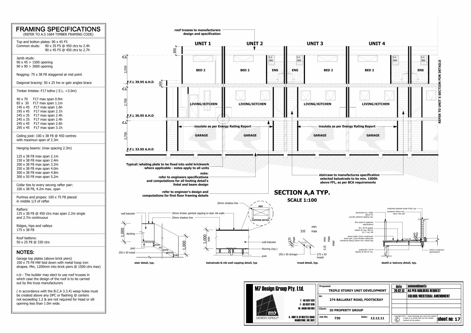
roof trusses to manufacturersdesign and specification
note:
refer to engineers specificationsand computations for all footing detail's
lintel and beam design
refer to engineer's design andcomputations for first floor framing details
selected balustrade to be min. 1000h
above FFL, as per BCA requirements
staircase to manufactures specification
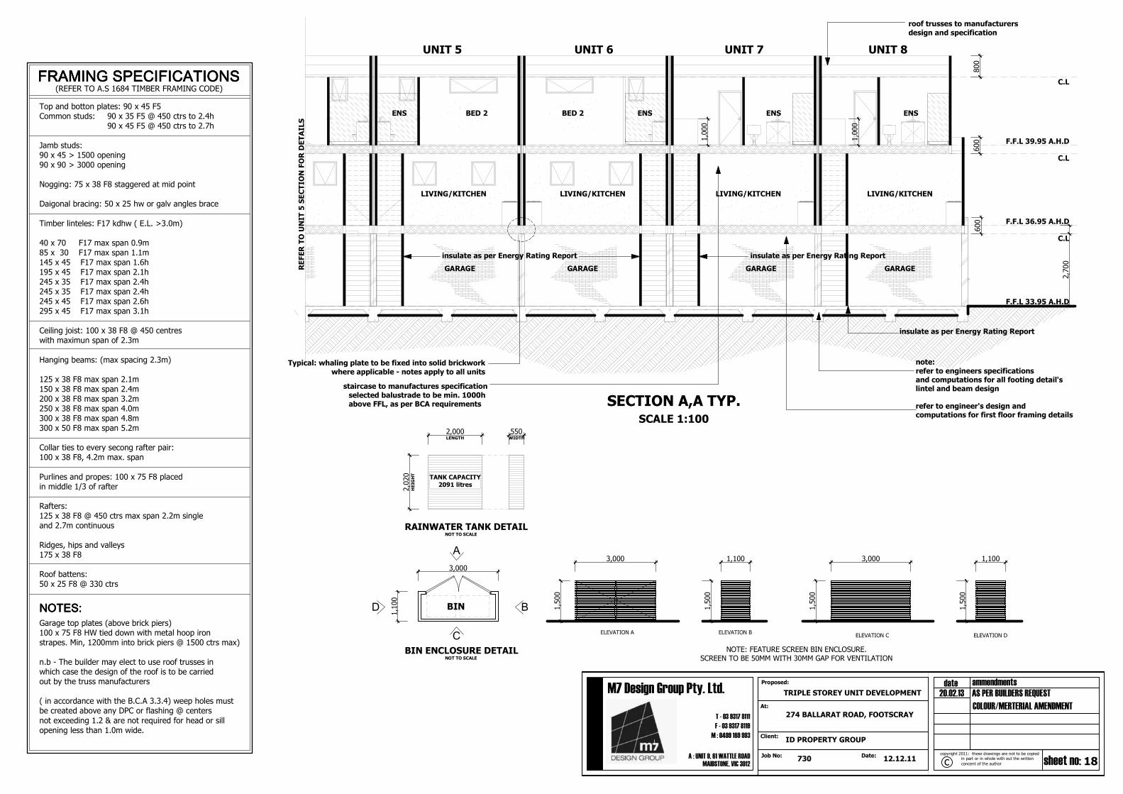
SECTION A,A TYP.SCALE 1:100
UNIT 1 UNIT 2 UNIT 3 UNIT 4
REFER TO UNIT 5 SECTION FOR DETAILSOBS
S.G
OBS
S.G
OBS
S.G
OBS
S.G
insulate as per Energy Rating Report insulate as per Energy Rating Report
Typical: whaling plate to be fixed into solid brickworkwhere applicable - notes apply to all units
Top and botton plates: 90 x 45 F5Common studs: 90 x 35 F5 @ 450 ctrs to 2.4h 90 x 45 F5 @ 450 ctrs to 2.7h
Jamb studs:90 x 45 > 1500 opening90 x 90 > 3000 opening
Nogging: 75 x 38 F8 staggered at mid point
Daigonal bracing: 50 x 25 hw or galv angles brace
Timber linteles: F17 kdhw ( E.L. >3.0m)
40 x 70 F17 max span 0.9m85 x 30 F17 max span 1.1m145 x 45 F17 max span 1.6h195 x 45 F17 max span 2.1h245 x 35 F17 max span 2.4h245 x 35 F17 max span 2.4h245 x 45 F17 max span 2.6h295 x 45 F17 max span 3.1h
Ceiling joist: 100 x 38 F8 @ 450 centreswith maximun span of 2.3m
Hanging beams: (max spacing 2.3m)
125 x 38 F8 max span 2.1m150 x 38 F8 max span 2.4m200 x 38 F8 max span 3.2m250 x 38 F8 max span 4.0m300 x 38 F8 max span 4.8m300 x 50 F8 max span 5.2m
Collar ties to every secong rafter pair:100 x 38 F8, 4.2m max. span
Purlines and propes: 100 x 75 F8 placedin middle 1/3 of rafter
Rafters:125 x 38 F8 @ 450 ctrs max span 2.2m singleand 2.7m continuous
Ridges, hips and valleys175 x 38 F8
Roof battens:50 x 25 F8 @ 330 ctrs
Garage top plates (above brick piers)100 x 75 F8 HW tied down with metal hoop ironstrapes. Min, 1200mm into brick piers @ 1500 ctrs max)
n.b - The builder may elect to use roof trusses inwhich case the design of the roof is to be carriedout by the truss manufacturers
( in accordance with the B.C.A 3.3.4) weep holes mustbe created above any DPC or flashing @ centersnot exceeding 1.2 & are not required for head or sillopening less than 1.0m wide.
selected balustrade to be min. 1000habove FFL, as per BCA requirements
staircase to manufactures specification
note:
refer to engineers specificationsand computations for all footing detail'slintel and beam design
refer to engineer's design andcomputations for first floor framing details
roof trusses to manufacturers
design and specification
SECTION A,A TYP.SCALE 1:100
UNIT 6 UNIT 7 UNIT 8UNIT 5
REFER TO UNIT 5 SECTION FOR DETAILS
Top and botton plates: 90 x 45 F5Common studs: 90 x 35 F5 @ 450 ctrs to 2.4h 90 x 45 F5 @ 450 ctrs to 2.7h
Jamb studs:90 x 45 > 1500 opening90 x 90 > 3000 opening
Nogging: 75 x 38 F8 staggered at mid point
Daigonal bracing: 50 x 25 hw or galv angles brace
Timber linteles: F17 kdhw ( E.L. >3.0m)
40 x 70 F17 max span 0.9m85 x 30 F17 max span 1.1m145 x 45 F17 max span 1.6h195 x 45 F17 max span 2.1h245 x 35 F17 max span 2.4h245 x 35 F17 max span 2.4h245 x 45 F17 max span 2.6h295 x 45 F17 max span 3.1h
Ceiling joist: 100 x 38 F8 @ 450 centreswith maximun span of 2.3m
Hanging beams: (max spacing 2.3m)
125 x 38 F8 max span 2.1m150 x 38 F8 max span 2.4m200 x 38 F8 max span 3.2m250 x 38 F8 max span 4.0m300 x 38 F8 max span 4.8m300 x 50 F8 max span 5.2m
Collar ties to every secong rafter pair:100 x 38 F8, 4.2m max. span
Purlines and propes: 100 x 75 F8 placedin middle 1/3 of rafter
Rafters:125 x 38 F8 @ 450 ctrs max span 2.2m singleand 2.7m continuous
Ridges, hips and valleys175 x 38 F8
Roof battens:50 x 25 F8 @ 330 ctrs
Garage top plates (above brick piers)100 x 75 F8 HW tied down with metal hoop ironstrapes. Min, 1200mm into brick piers @ 1500 ctrs max)
n.b - The builder may elect to use roof trusses inwhich case the design of the roof is to be carriedout by the truss manufacturers
( in accordance with the B.C.A 3.3.4) weep holes mustbe created above any DPC or flashing @ centers
not exceeding 1.2 & are not required for head or sillopening less than 1.0m wide.
NOTE: FEATURE SCREEN BIN ENCLOSURE.SCREEN TO BE 50MM WITH 30MM GAP FOR VENTILATION
BIN ENCLOSURE DETAILNOT TO SCALE
insulate as per Energy Rating Report insulate as per Energy Rating Report
insulate as per Energy Rating Report
Typical: whaling plate to be fixed into solid brickwork
where applicable - notes apply to all units
RAINWATER TANK DETAILNOT TO SCALE
HEIGHT
LENGTH WIDTH
TANK CAPACITY2091 litres
19
M : 0409 169 993
Proposed: ammendmentsdate
concent of the author
in part or in whole with out the written sheet no:Date:
M7 Design Group Pty. Ltd.
cJob No:A : UNIT 9, 61 WATTLE ROAD
MAIDSTONE, VIC 3012
Client:
At:
F - 03 9317 8119
T - 03 9317 8111
copyright 2011: these drawings are not to be copied
730 12.12.11
274 BALLARAT ROAD, FOOTSCRAY
ID PROPERTY GROUP
TRIPLE STOREY UNIT DEVELOPMENT 20.02.13 AS PER BUILDERS REQUEST
COLOUR/MERTERIAL AMENDMENT
F. DENOTES - Fixed Glazing
O. DENOTES - Openable GlazingSL. DENOTES - Sliding Door
OBS DENOTES - Obscured GlazingSG DENOTES - Safety Glass as per AS1288
CP DENOTES - All glazing to be pilkington comfort plus or similar
NOTE:WINDOWS SIZES AND STYLES ARE NOMINAL ONLY & AREMEASURED INTERNALLYBETWEEN REVEALS. ACTUAL WINDOW SIZES MAY VARYDEPENDING ON THEMANUFACTURERS STANDARDS. THE OWNER IS TOCONFIRM THE SIZES WITH THEBUILDER'S WINDOW MANUFACTURER PRIOR TOCOMMENCEMENT. WINDOWS TO BEFLASHED AS REQUIRED ALL WINDOWS ARE TO BE INACCORDANCE WITH A.S. 1288
WINDOW LEGEND
NOTE:WINDOWS SIZES AND STYLES ARE NOMINAL ONLY & ARE MEASURED INTERNALLY
BETWEEN REVEALS. ACTUAL WINDOW SIZES MAY VARY DEPENDING ON THE
MANUFACTURERS STANDARDS. THE OWNER IS TO CONFIRM THE SIZES WITH THE
BUILDER'S WINDOW MANUFACTURER PRIOR TO COMMENCEMENT. WINDOWS TO BEFLASHED AS REQUIRED ALL WINDOWS ARE TO BE IN ACCORDANCE WITH A.S. 1288
F. DENOTES - Fixed Glazing
O. DENOTES - Openable GlazingSL. DENOTES - Sliding Door
OBS DENOTES - Obscured GlazingSG DENOTES - Safety Glass as per AS1288
CP DENOTES - All glazing to be pilkington comfort plus or similar
20
M : 0409 169 993
Proposed: ammendmentsdate
concent of the author
in part or in whole with out the written sheet no:Date:
M7 Design Group Pty. Ltd.
cJob No:A : UNIT 9, 61 WATTLE ROAD
MAIDSTONE, VIC 3012
Client:
At:
F - 03 9317 8119
T - 03 9317 8111
copyright 2011: these drawings are not to be copied
730 12.12.11
274 BALLARAT ROAD, FOOTSCRAY
ID PROPERTY GROUP
TRIPLE STOREY UNIT DEVELOPMENT 20.02.13 AS PER BUILDERS REQUEST
COLOUR/MERTERIAL AMENDMENTNOTE:WINDOWS SIZES AND STYLES ARE NOMINAL ONLY & AREMEASURED INTERNALLYBETWEEN REVEALS. ACTUAL WINDOW SIZES MAY VARYDEPENDING ON THEMANUFACTURERS STANDARDS. THE OWNER IS TOCONFIRM THE SIZES WITH THEBUILDER'S WINDOW MANUFACTURER PRIOR TOCOMMENCEMENT. WINDOWS TO BEFLASHED AS REQUIRED ALL WINDOWS ARE TO BE INACCORDANCE WITH A.S. 1288
WINDOW LEGEND
NOTE:
WINDOWS SIZES AND STYLES ARE NOMINAL ONLY & ARE MEASURED INTERNALLY
BETWEEN REVEALS. ACTUAL WINDOW SIZES MAY VARY DEPENDING ON THE
MANUFACTURERS STANDARDS. THE OWNER IS TO CONFIRM THE SIZES WITH THEBUILDER'S WINDOW MANUFACTURER PRIOR TO COMMENCEMENT. WINDOWS TO BE
FLASHED AS REQUIRED ALL WINDOWS ARE TO BE IN ACCORDANCE WITH A.S. 1288
F. DENOTES - Fixed GlazingO. DENOTES - Openable Glazing
SL. DENOTES - Sliding DoorOBS DENOTES - Obscured Glazing
SG DENOTES - Safety Glass as per AS1288CP DENOTES - All glazing to be pilkington comfort plus or similar
2,400
3,200
2,400
3,200
2,400
3,200
2,400
3,200820
2,100
2,400
820
2,400
3,000
820
2,100
820
2,100
2,100
3,600
2,100
3,600
2,100
820
2,400
3,200
2,400
3,200
2,100
3,600
2,100
820
2,400
3,200
2,400
3,200
2,100
3,600
2,100
820
2,400
3,200
2,400
3,200
2,100
3,600
2,100
820
2,400
3,200
2,400
3,200
2,100
3,600
2,100
820
2,400
3,200
2,400
3,200
2,100
3,600 3,600
2,100
SLIDING DOOR
UNIT 2
D01
ENTRY DOOR PANEL LIFT DOOR
D02 D03
SLIDING DOOR
UNIT 8
D01
ENTRY DOOR PANEL LIFT DOOR
D02 D03
SLIDING DOOR
D01
ENTRY DOOR PANEL LIFT DOOR
D02 D03
SLIDING DOOR
D01
ENTRY DOOR PANEL LIFT DOOR
D02 D04
GARAGE DOOR
UNIT 1
D01
ENTRY DOOR PANEL LIFT DOOR
D02
SLIDING DOOR
D03
SLIDING DOOR
D03
10.38 lanminated glass or 6/12/10.38SLIDING DOOR
UNIT 3
D01
ENTRY DOOR PANEL LIFT DOOR
D02 D03
SLIDING DOOR
D01
ENTRY DOOR PANEL LIFT DOOR
D02 D03
10.38 lanminated glass or 6/12/10.38 10.38 lanminated glass or 6/12/10.38
SLIDING DOOR
UNIT 4
D01
ENTRY DOOR PANEL LIFT DOOR
D02 D03
SLIDING DOOR
D01
ENTRY DOOR PANEL LIFT DOOR
D02 D03
SLIDING DOOR
UNIT 5
D01
ENTRY DOOR PANEL LIFT DOOR
D02 D03
SLIDING DOOR
D01
ENTRY DOOR PANEL LIFT DOOR
D02 D03
10.38 lanminated glass or 6/12/10.38 6.38 lanminated glass
SLIDING DOOR
UNIT 6
D01
ENTRY DOOR PANEL LIFT DOOR
D02 D03
SLIDING DOOR
D01
ENTRY DOOR PANEL LIFT DOOR
D02 D03
6.38 lanminated glass
SLIDING DOOR
UNIT 7
D01
ENTRY DOOR PANEL LIFT DOOR
D02 D03
SLIDING DOOR
D01
ENTRY DOOR PANEL LIFT DOOR
D02 D03
6.38 lanminated glass 6.38 lanminated glass
The following standards are to be implemented at U-1/2/5/7
274 Ballarat Rd Footscray 3011 to obtain a 6.0 star energy
rating.
- Glazing to be Aluminium Awning Window-Single glazed: 6.38mm Comfort PlusNeutral U-Value (4.27) SHGC (0.45) or similar.- Sliding doors Aluminium Sliding Doors-Single Glazed: 6.38 mm Comfort PlusNeutral U-Value (4.94) SHGC (0.46) or similar.
UNIT 1, UNIT 2, UNIT 5, UNIT 7
The following standards are to be implemented at U-3/8
274 Ballarat Rd Footscray 3011 to obtain a 6.0 star energy
rating.
- Glazing to be Aluminium Awning Window-Single glazed: 6.38mm Comfort PlusNeutral U-Value (4.27) SHGC (0.45) or similar.- Sliding doors Aluminium Sliding Doors-Single Glazed: 6.38 mm Comfort PlusNeutral U-Value (4.94) SHGC (0.46) or similar.
UNIT 3, UNIT 8,
The following standards are to be implemented at U-4/6
274 Ballarat Rd Footscray 3011 to obtain a 6.0 star energy
rating.
- Glazing to be Aluminium Awning Window-Single glazed: 6.38mm Comfort PlusNeutral U-Value (4.27) SHGC (0.45) or similar.- Sliding doors Aluminium Sliding Doors-Single Glazed: 6.38 mm Comfort PlusNeutral U-Value (4.94) SHGC (0.46) or similar.
UNIT 4, UNIT 6
21
M : 0409 169 993
Proposed: ammendmentsdate
concent of the author
in part or in whole with out the written sheet no:Date:
M7 Design Group Pty. Ltd.
cJob No:A : UNIT 9, 61 WATTLE ROAD
MAIDSTONE, VIC 3012
Client:
At:
F - 03 9317 8119
T - 03 9317 8111
copyright 2011: these drawings are not to be copied
730 12.12.11
274 BALLARAT ROAD, FOOTSCRAY
ID PROPERTY GROUP
TRIPLE STOREY UNIT DEVELOPMENT 20.02.13 AS PER BUILDERS REQUEST
COLOUR/MERTERIAL AMENDMENTNOTE:WINDOWS SIZES AND STYLES ARE NOMINAL ONLY & AREMEASURED INTERNALLYBETWEEN REVEALS. ACTUAL WINDOW SIZES MAY VARYDEPENDING ON THEMANUFACTURERS STANDARDS. THE OWNER IS TOCONFIRM THE SIZES WITH THEBUILDER'S WINDOW MANUFACTURER PRIOR TOCOMMENCEMENT. WINDOWS TO BEFLASHED AS REQUIRED ALL WINDOWS ARE TO BE INACCORDANCE WITH A.S. 1288
WINDOW LEGEND
NOTE:WINDOWS SIZES AND STYLES ARE NOMINAL ONLY & ARE MEASURED INTERNALLY
BETWEEN REVEALS. ACTUAL WINDOW SIZES MAY VARY DEPENDING ON THE
MANUFACTURERS STANDARDS. THE OWNER IS TO CONFIRM THE SIZES WITH THE
BUILDER'S WINDOW MANUFACTURER PRIOR TO COMMENCEMENT. WINDOWS TO BEFLASHED AS REQUIRED ALL WINDOWS ARE TO BE IN ACCORDANCE WITH A.S. 1288
F. DENOTES - Fixed Glazing
O. DENOTES - Openable GlazingSL. DENOTES - Sliding Door
OBS DENOTES - Obscured GlazingSG DENOTES - Safety Glass as per AS1288
CP DENOTES - All glazing to be pilkington comfort plus or similar