85
ZXV10 T700 General Operation Guide Version: V1.1.4 ZTE USA Inc. 2425 N Central Expressway, Suite 600, Richardson TX. 75080 Email: [email protected]
ZXV10 T700General Operation Guide
Version: V1.1.4
ZTE USA Inc.2425 N Central Expressway, Suite 600, Richardson TX. 75080Email: [email protected]
LEGAL INFORMATIONCopyright © 2014 ZTE CORPORATION.
The contents of this document are protected by copyright laws and international treaties. Any reproduction or
distribution of this document or any portion of this document, in any form by any means, without the prior written
consent of ZTE CORPORATION is prohibited. Additionally, the contents of this document are protected by
contractual confidentiality obligations.
All company, brand and product names are trade or service marks, or registered trade or service marks, of ZTE
CORPORATION or of their respective owners.
This document is provided “as is”, and all express, implied, or statutory warranties, representations or conditions
are disclaimed, including without limitation any implied warranty of merchantability, fitness for a particular purpose,
title or non-infringement. ZTE CORPORATION and its licensors shall not be liable for damages resulting from the
use of or reliance on the information contained herein.
ZTE CORPORATION or its licensors may have current or pending intellectual property rights or applications
covering the subject matter of this document. Except as expressly provided in any written license between ZTE
CORPORATION and its licensee, the user of this document shall not acquire any license to the subject matter
herein.
ZTE CORPORATION reserves the right to upgrade or make technical change to this product without further notice.
Users may visit ZTE technical support website http://ensupport.zte.com.cn to inquire related information.
The ultimate right to interpret this product resides in ZTE CORPORATION.
Revision History
Revision No. Revision Date Revision Reason
R1.0 2014-02-15 First edition
Serial Number: SJ-20140210102518-003
Publishing Date: 2014-02-15 (R1.0)
SJ-20140210102518-003|2014-02-15 (R1.0) ZTE Proprietary and Confidential
ContentsAbout This Manual ......................................................................................... I
Chapter 1 Guide for New Users................................................................. 1-11.1 Getting Started................................................................................................... 1-1
1.2 Understanding Terminal Control Methods ............................................................ 1-2
1.3 Validating Terminal Settings ................................................................................ 1-4
1.4 Performing Basic Configuration ........................................................................... 1-4
1.5 Conference Operations..................................................................................... 1-10
1.5.1 Placing a Point-to-Point Call.................................................................... 1-10
1.5.2 Placing a Multipoint Call Through the Embedded MCU ............................. 1-13
1.5.3 Placing a Multipoint Call Through the MCU Server ................................... 1-15
1.5.4 Placing a Multipoint Audio Call Without an MCU ...................................... 1-16
1.5.5 Calling the Microsoft Lync Account ......................................................... 1-16
1.5.6 Disconnecting a Call............................................................................... 1-18
1.6 Logging in to the Web Page .............................................................................. 1-19
1.7 Operating PC Console...................................................................................... 1-20
1.7.1 Installing the PC Console........................................................................ 1-20
1.7.2 Logging in to the PC Console.................................................................. 1-21
Chapter 2 General Audio Operations ....................................................... 2-12.1 Adjusting Output Volume .................................................................................... 2-1
2.2 Adjusting Input Volume ....................................................................................... 2-2
Chapter 3 General Video Operations........................................................ 3-13.1 Operating Camera.............................................................................................. 3-1
3.1.1 Controlling the Local Camera .................................................................... 3-1
3.1.2 Enabling the Remote Terminal to Control the Local Camera........................ 3-2
3.1.3 Controlling the Remote Camera ................................................................ 3-3
3.1.4 Presetting the Position of the Camera........................................................ 3-4
3.1.5 Activating the Preset Position.................................................................... 3-5
3.1.6 Setting the Camera .................................................................................. 3-7
3.2 Operating Screen Display ................................................................................... 3-9
3.2.1 Adjusting Display Mode ............................................................................ 3-9
3.2.2 Adjusting the Position of Picture-in-Picture................................................. 3-9
3.2.3 Learning Terminal Icons...........................................................................3-11
3.2.4 Setting Icons Displaying Mode ................................................................ 3-13
I
SJ-20140210102518-003|2014-02-15 (R1.0) ZTE Proprietary and Confidential
3.3 Setting Video ................................................................................................... 3-14
3.3.1 Setting Video Output .............................................................................. 3-14
3.3.2 Setting Video Input ................................................................................ 3-17
3.3.3 Selecting the Local/Remote Primary Video Source ................................... 3-19
3.3.4 Selecting a Presentation Source.............................................................. 3-21
Chapter 4 General Operations of Conference Control ........................... 4-14.1 Viewing In-Conference Terminals ........................................................................ 4-1
4.2 Applying and Releasing Chairman....................................................................... 4-1
4.3 Selecting the Broadcast Source .......................................................................... 4-2
4.4 Viewing Other Conference Sites.......................................................................... 4-4
4.5 Controlling Conference Sound ............................................................................ 4-5
4.6 Conference Management.................................................................................... 4-6
4.6.1 Adding Terminal ....................................................................................... 4-6
4.6.2 Disconnecting a terminal........................................................................... 4-7
4.6.3 Prolonging a Conference .......................................................................... 4-7
4.6.4 Ending a Conference................................................................................ 4-8
Chapter 5 Dual Video Operation ............................................................... 5-15.1 Overview of Dual Video Streaming ...................................................................... 5-1
5.2 Managing a Presentation .................................................................................... 5-2
5.3 Displaying Presentations .................................................................................... 5-4
Chapter 6 Personalized Settings............................................................... 6-16.1 Setting Volume Display Mode.............................................................................. 6-1
6.2 Showing or Hiding the Local Conference Site Name ............................................. 6-2
6.3 Setting the Transparency of the GUI ................................................................... 6-2
6.4 Setting the Logo of the GUI................................................................................. 6-3
6.5 Configuring the Logo On the Web........................................................................ 6-4
6.6 Configuring Call Answering Mode........................................................................ 6-5
6.7 Adjusting Display Mode of Conference List on PC Console ................................... 6-6
Chapter 7 Other Operations ...................................................................... 7-17.1 Viewing Version Information................................................................................ 7-1
7.2 Performing Network Test..................................................................................... 7-1
7.3 Key Combinations of the Remote Control............................................................. 7-2
Figures............................................................................................................. I
Tables ............................................................................................................ III
Glossary .........................................................................................................V
II
SJ-20140210102518-003|2014-02-15 (R1.0) ZTE Proprietary and Confidential
About This ManualPurposeThe ZXV10 T700 is the ZTE-developed HD video conference terminal for HD videoconferencing.
This manual describes how to use the ZXV10 T700HD terminal through the remote control,Web page, and PC console. Themultipoint conference operations described in thismanualis to be applied in the multipoint conferences held on the multimedia video servers (suchas ZXV10 M900) developed by ZTE.
Intended AudienceThis document is intended for:l Terminal usersl Conference administrators
What Is in This ManualThis manual contains the following chapters.
Chapter 1, Guide for New
Users
Describes the basic configuration and operations for new users.
Chapter 2, General Audio
Operations
Describes how to operate audio input and output.
Chapter 3, General Video
Operations
Describes how to operate camera, screen display, and video input and
output.
Chapter 4, General
Operations of Multipoint
Conference Control
Describes the common operations in a conference.
Chapter 5, Dual Video
Operations
Describes how to preview, send and close dual video through the
remote control, Web page or PC console.
Chapter 6, Personalized
Settings
Describes how to personalize the logo, display modes, answering
modes and display modes of the PC console.
Chapter 7, Other
Operations
Describes some other operations such as viewing the system version
and how to test the network and the key combinations.
Related DocumentationThe following documentation is related to this manual:l ZXV10 T700 Quick Start Guidel ZXV10 T700 Product Descriptionl ZXV10 T700 Remote Control Operation Guide
I
SJ-20140210102518-003|2014-02-15 (R1.0) ZTE Proprietary and Confidential
l ZXV10 T700 Web Page Operation Guidel ZXV10 T700 PC Console Operation Guidel Remote Control User Guidel ZXV10 Video Conference Terminal VCT Console Operation Guide (iPad)
ConventionsThis manual uses the following conventions.
Caution: indicates a potentially hazardous situation. Failure to
comply can result in moderate injury, equipment damage, or
interruption of minor services.
Note: provides additional information about a topic.
II
SJ-20140210102518-003|2014-02-15 (R1.0) ZTE Proprietary and Confidential
Chapter 1Guide for New UsersTable of ContentsGetting Started ...........................................................................................................1-1Understanding Terminal Control Methods ..................................................................1-2Validating Terminal Settings........................................................................................1-4Performing Basic Configuration ..................................................................................1-4Conference Operations ............................................................................................1-10Logging in to the Web Page .....................................................................................1-19Operating PC Console .............................................................................................1-20
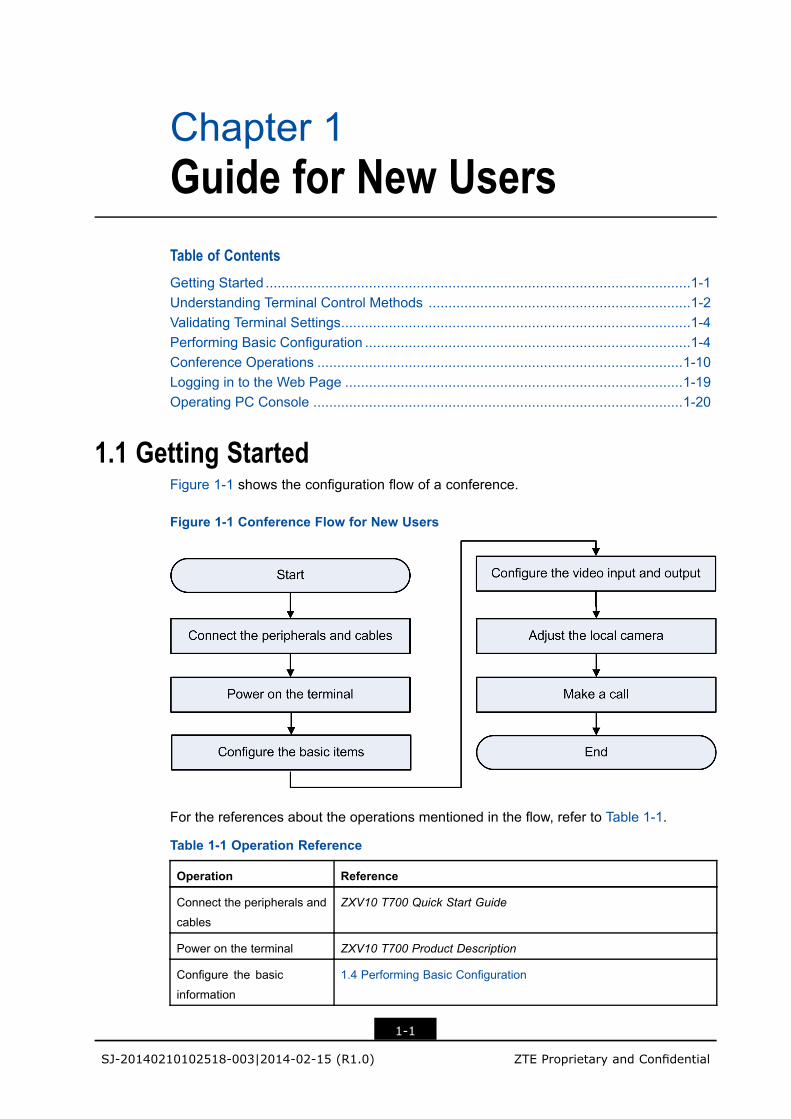
1.1 Getting StartedFigure 1-1 shows the configuration flow of a conference.
Figure 1-1 Conference Flow for New Users
For the references about the operations mentioned in the flow, refer to Table 1-1.
Table 1-1 Operation Reference
Operation Reference
Connect the peripherals and
cables
ZXV10 T700 Quick Start Guide
Power on the terminal ZXV10 T700 Product Description
Configure the basic
information
1.4 Performing Basic Configuration
1-1
SJ-20140210102518-003|2014-02-15 (R1.0) ZTE Proprietary and Confidential
ZXV10 T700 General Operation Guide
Operation Reference
Configure the video input
and output
3.3.1 Setting Video Output
3.3.2 Setting Video Input
Adjust the local camera 3.1.1 Controlling the Local Camera
Make a call 1.5.1 Placing a Point-to-Point Call
1.5.2 Placing a Multipoint Call Through the Embedded MCU
1.5.3 Placing a Multipoint Call Through the MCU Server
1.5.4 Placing a Multipoint Audio Call Without an MCU
1.5.5 Calling the Microsoft Lync Account
1.2 Understanding Terminal Control MethodsThe ZXV10 T700 terminal supports the following control methods:l GUI on remote controll Web pagel PC consolel VCT consoleFor the typical application scenario of each mode, refer to Table 1-2.
Table 1-2 Typical Application Scenario of Each Conference Control Mode
Operation GUI on RemoteControl
Web Page PC Console VCT Console
Daily
configuration and
modification
√ √ - -
Conference
control
√ √ √ √
Multi-point
conference
control
√ - √ √
Message sending √ √ √ -
System
maintenance
√ √ - -
System
diagnostics
√ √ √ √
The control methods are described as follows:l GUI on remote control: the ZXV10 T700 terminal is controlled by using a remote
control.
1-2
SJ-20140210102518-003|2014-02-15 (R1.0) ZTE Proprietary and Confidential
Chapter 1 Guide for New Users
Caution!
If the remote control is not sensitive, check whether the battery needs to be replaced.
l Web page: The ZXV10 T700 terminal is controlled by logging in to the terminal Webpage. For how to log in, refer to 1.6 Logging in to the Web Page.
l PC console: The ZXV10 T700 terminal is controlled through the PC console softwarethat is installed on the PC. For how to install and log in, refer to 1.7.1 Installing the PCConsole and 1.7.2 Logging in to the PC Console.
l VCT console: The ZXV10 T700 terminal is controlled through the VCT consolesoftware that is installed on the iPad. For the operation guide for the VCT console,refer to the ZXV10 Video Conference Terminal VCT Console Operation Guide (iPad).
Daily Configuration and ModificationYou can perform daily configuration for the ZXV10 T700 terminal in either of the followingtwo ways:1. GUI on the remote control: Open the main screen by pressing Menu. Use the arrow
keys and the OK key on the remote control to display the configuration page, modifythe parameters and save the modification.
2. Web page: Open the terminal configuration Web page. Modify the parameters andsave the modification.
Starting a ConferenceYou can start a conference with the ZXV10 T700 terminal in any of the following threeways:l GUI on the remote control: Press the Call key or Menu on the remote control to start
a conference on the screen displayed.l Web page: Open the Web page of the terminal and start a conference by selecting
Call Control > Call/Disconnect.l PC console: Log in to the PC console of the terminal and initiate a conference by
selecting > Call Control.
Conference ControlYou can control a conference in the Conference Control page. You can open theConference Control page in either of the following two ways:l GUI on the remote control: Press the Conf key on the remote control.
l PC console: Log in to the PC console of the terminal, and select > Call Control.
1-3
SJ-20140210102518-003|2014-02-15 (R1.0) ZTE Proprietary and Confidential
ZXV10 T700 General Operation Guide
1.3 Validating Terminal SettingsThe terminal configuration can bemodified only when the terminals are not in a conference.
After the configuration is modified, Perform the follow steps to save the modification andmake the settings take effect.
Stepsl Validate terminal settings with the remote control.
a. After the terminal information is modified, press the Return key on the remotecontrol. A confirmation dialog box is displayed.
b. Select the OK button on the screen, and press the OK key on the remote control.
l Validate terminal settings on the Web page.
a. After the terminal information is modified, click the OK button at the lower part ofthe Web page to save it.
– End of Steps –
1.4 Performing Basic ConfigurationIf the ZXV10 T700 is used for the first time, the setup wizard is displayed after the ZXV10T700 is powered on. The administrator can set the parameters by following the wizard’sinstructions.
If the Guide remind next time check box is selected, the setup wizard is displayed afterthe ZXV10 T700 is restarted.
ContextIf a terminal is not configured with network information (for example, an IP address), youcan configure it through the remote control instead of the Web page.
You can also select > System > Setup Guide with the remote control to display thesystem setup wizard.
Steps1. On the system setup wizard, select the Guide remind next time check box.
Note:
If you select the Guide remind next time check box, the Setup Guide dialog box isdisplayed when the terminal is started the next time.
1-4
SJ-20140210102518-003|2014-02-15 (R1.0) ZTE Proprietary and Confidential
Chapter 1 Guide for New Users
2. Select a language and click Next.
3. Set the date and time of the system, and click Next. For the related operations, referto Table 1-3.
Table 1-3 Operations for Setting Date and Time
To……… Do………
Use SNTP Server to
Synchronize Time
i. Set the SNTP to Enable.
ii. Set the address of the SNTP Server.
iii. Select the Time Zone of the terminal.
Set the Local Time Manuallyi. Set the SNTP to Disable.
ii. Set the Date Format, Date, and Time.
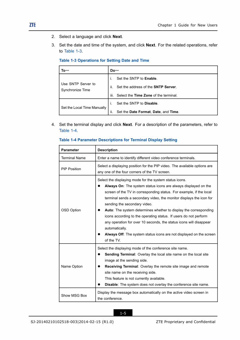
4. Set the terminal display and click Next. For a description of the parameters, refer toTable 1-4.
Table 1-4 Parameter Descriptions for Terminal Display Setting
Parameter Description
Terminal Name Enter a name to identify different video conference terminals.
PIP PositionSelect a displaying position for the PIP video. The available options are
any one of the four corners of the TV screen.
OSD Option
Select the displaying mode for the system status icons.
l Always On: The system status icons are always displayed on the
screen of the TV in corresponding status. For example, if the local
terminal sends a secondary video, the monitor displays the icon for
sending the secondary video.
l Auto: The system determines whether to display the corresponding
icons according to the operating status. If users do not perform
any operation for over 10 seconds, the status icons will disappear
automatically.
l Always Off: The system status icons are not displayed on the screen
of the TV.
Name Option
Select the displaying mode of the conference site name.
l Sending Terminal: Overlay the local site name on the local siteimage at the sending side.
l Receiving Terminal: Overlay the remote site image and remotesite name on the receiving side.
This feature is not currently available.
l Disable: The system does not overlay the conference site name.
Show MSG BoxDisplay the message box automatically on the active video screen in
the conference.
1-5
SJ-20140210102518-003|2014-02-15 (R1.0) ZTE Proprietary and Confidential
ZXV10 T700 General Operation Guide
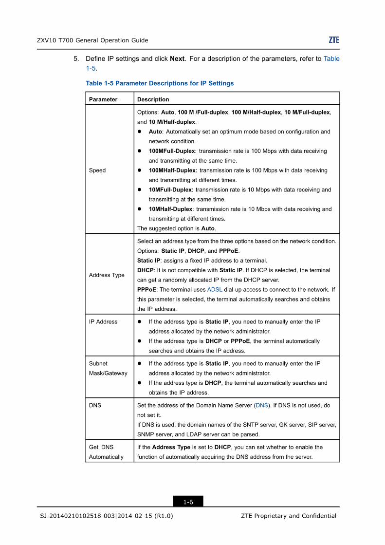
5. Define IP settings and click Next. For a description of the parameters, refer to Table1-5.
Table 1-5 Parameter Descriptions for IP Settings
Parameter Description
Speed
Options: Auto, 100 M /Full-duplex, 100 M/Half-duplex, 10 M/Full-duplex,and 10 M/Half-duplex.l Auto: Automatically set an optimum mode based on configuration and
network condition.
l 100MFull-Duplex: transmission rate is 100 Mbps with data receivingand transmitting at the same time.
l 100MHalf-Duplex: transmission rate is 100 Mbps with data receivingand transmitting at different times.
l 10MFull-Duplex: transmission rate is 10 Mbps with data receiving andtransmitting at the same time.
l 10MHalf-Duplex: transmission rate is 10 Mbps with data receiving andtransmitting at different times.
The suggested option is Auto.
Address Type
Select an address type from the three options based on the network condition.
Options: Static IP, DHCP, and PPPoE.Static IP: assigns a fixed IP address to a terminal.
DHCP: It is not compatible with Static IP. If DHCP is selected, the terminal
can get a randomly allocated IP from the DHCP server.
PPPoE: The terminal uses ADSL dial-up access to connect to the network. Ifthis parameter is selected, the terminal automatically searches and obtains
the IP address.
IP Address l If the address type is Static IP, you need to manually enter the IP
address allocated by the network administrator.
l If the address type is DHCP or PPPoE, the terminal automatically
searches and obtains the IP address.
Subnet
Mask/Gateway
l If the address type is Static IP, you need to manually enter the IP
address allocated by the network administrator.
l If the address type is DHCP, the terminal automatically searches andobtains the IP address.
DNS Set the address of the Domain Name Server (DNS). If DNS is not used, do
not set it.
If DNS is used, the domain names of the SNTP server, GK server, SIP server,
SNMP server, and LDAP server can be parsed.
Get DNS
Automatically
If the Address Type is set to DHCP, you can set whether to enable thefunction of automatically acquiring the DNS address from the server.
1-6
SJ-20140210102518-003|2014-02-15 (R1.0) ZTE Proprietary and Confidential
Chapter 1 Guide for New Users
Parameter Description
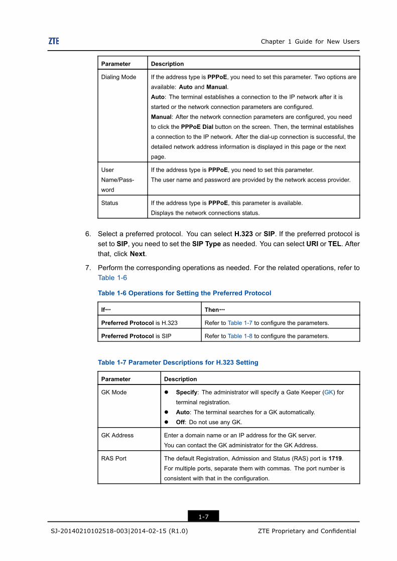
Dialing Mode If the address type is PPPoE, you need to set this parameter. Two options areavailable: Auto and Manual.Auto: The terminal establishes a connection to the IP network after it is
started or the network connection parameters are configured.
Manual: After the network connection parameters are configured, you needto click the PPPoE Dial button on the screen. Then, the terminal establishesa connection to the IP network. After the dial-up connection is successful, the
detailed network address information is displayed in this page or the next
page.
User
Name/Pass-
word
If the address type is PPPoE, you need to set this parameter.The user name and password are provided by the network access provider.
Status If the address type is PPPoE, this parameter is available.Displays the network connections status.
6. Select a preferred protocol. You can select H.323 or SIP. If the preferred protocol isset to SIP, you need to set the SIP Type as needed. You can select URI or TEL. Afterthat, click Next.
7. Perform the corresponding operations as needed. For the related operations, refer toTable 1-6
Table 1-6 Operations for Setting the Preferred Protocol
If……… Then………
Preferred Protocol is H.323 Refer to Table 1-7 to configure the parameters.
Preferred Protocol is SIP Refer to Table 1-8 to configure the parameters.
Table 1-7 Parameter Descriptions for H.323 Setting
Parameter Description
GK Mode l Specify: The administrator will specify a Gate Keeper (GK) forterminal registration.
l Auto: The terminal searches for a GK automatically.
l Off: Do not use any GK.
GK Address Enter a domain name or an IP address for the GK server.
You can contact the GK administrator for the GK Address.
RAS Port The default Registration, Admission and Status (RAS) port is 1719.For multiple ports, separate them with commas. The port number is
consistent with that in the configuration.
1-7
SJ-20140210102518-003|2014-02-15 (R1.0) ZTE Proprietary and Confidential
ZXV10 T700 General Operation Guide
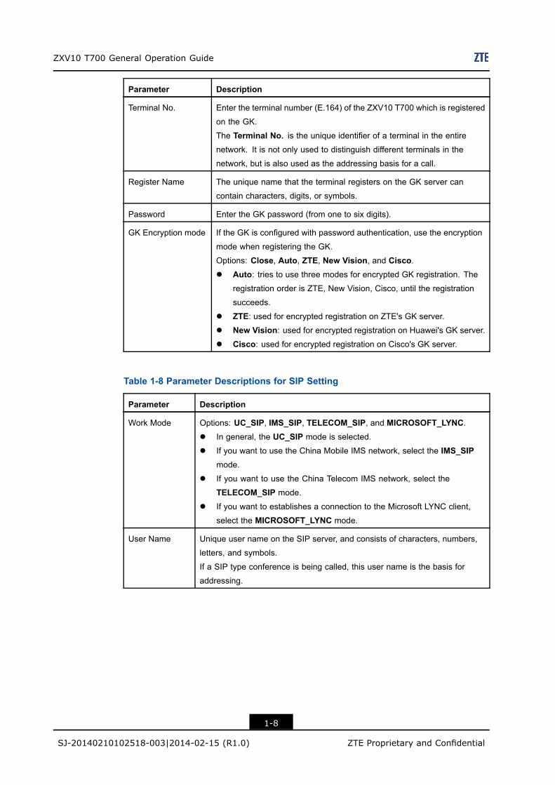
Parameter Description
Terminal No. Enter the terminal number (E.164) of the ZXV10 T700 which is registered
on the GK.
The Terminal No. is the unique identifier of a terminal in the entirenetwork. It is not only used to distinguish different terminals in the
network, but is also used as the addressing basis for a call.
Register Name The unique name that the terminal registers on the GK server can
contain characters, digits, or symbols.
Password Enter the GK password (from one to six digits).
GK Encryption mode If the GK is configured with password authentication, use the encryption
mode when registering the GK.
Options: Close, Auto, ZTE, New Vision, and Cisco.l Auto: tries to use three modes for encrypted GK registration. The
registration order is ZTE, New Vision, Cisco, until the registration
succeeds.
l ZTE: used for encrypted registration on ZTE's GK server.
l New Vision: used for encrypted registration on Huawei's GK server.
l Cisco: used for encrypted registration on Cisco's GK server.
Table 1-8 Parameter Descriptions for SIP Setting
Parameter Description
Work Mode Options: UC_SIP, IMS_SIP, TELECOM_SIP, and MICROSOFT_LYNC.l In general, the UC_SIP mode is selected.
l If you want to use the China Mobile IMS network, select the IMS_SIPmode.
l If you want to use the China Telecom IMS network, select the
TELECOM_SIP mode.
l If you want to establishes a connection to the Microsoft LYNC client,
select the MICROSOFT_LYNC mode.
User Name Unique user name on the SIP server, and consists of characters, numbers,
letters, and symbols.
If a SIP type conference is being called, this user name is the basis for
addressing.
1-8
SJ-20140210102518-003|2014-02-15 (R1.0) ZTE Proprietary and Confidential
Chapter 1 Guide for New Users
Parameter Description
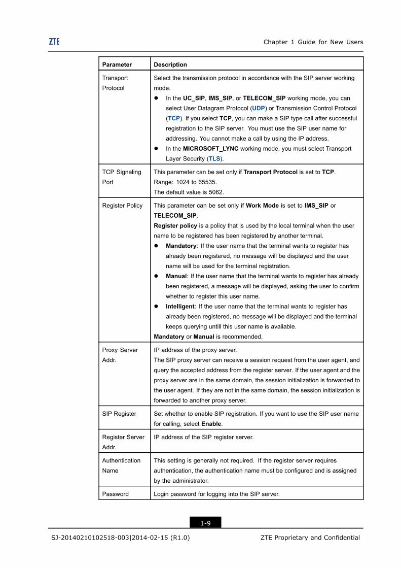
Transport
Protocol
Select the transmission protocol in accordance with the SIP server working
mode.
l In the UC_SIP, IMS_SIP, or TELECOM_SIP working mode, you can
select User Datagram Protocol (UDP) or Transmission Control Protocol(TCP). If you select TCP, you can make a SIP type call after successful
registration to the SIP server. You must use the SIP user name for
addressing. You cannot make a call by using the IP address.
l In the MICROSOFT_LYNC working mode, you must select Transport
Layer Security (TLS).
TCP Signaling
Port
This parameter can be set only if Transport Protocol is set to TCP.Range: 1024 to 65535.
The default value is 5062.
Register Policy This parameter can be set only if Work Mode is set to IMS_SIP or
TELECOM_SIP.Register policy is a policy that is used by the local terminal when the username to be registered has been registered by another terminal.
l Mandatory: If the user name that the terminal wants to register hasalready been registered, no message will be displayed and the user
name will be used for the terminal registration.
l Manual: If the user name that the terminal wants to register has alreadybeen registered, a message will be displayed, asking the user to confirm
whether to register this user name.
l Intelligent: If the user name that the terminal wants to register hasalready been registered, no message will be displayed and the terminal
keeps querying untill this user name is available.
Mandatory or Manual is recommended.
Proxy Server
Addr.
IP address of the proxy server.
The SIP proxy server can receive a session request from the user agent, and
query the accepted address from the register server. If the user agent and the
proxy server are in the same domain, the session initialization is forwarded to
the user agent. If they are not in the same domain, the session initialization is
forwarded to another proxy server.
SIP Register Set whether to enable SIP registration. If you want to use the SIP user name
for calling, select Enable.
Register Server
Addr.
IP address of the SIP register server.
Authentication
Name
This setting is generally not required. If the register server requires
authentication, the authentication name must be configured and is assigned
by the administrator.
Password Login password for logging into the SIP server.
1-9
SJ-20140210102518-003|2014-02-15 (R1.0) ZTE Proprietary and Confidential
ZXV10 T700 General Operation Guide
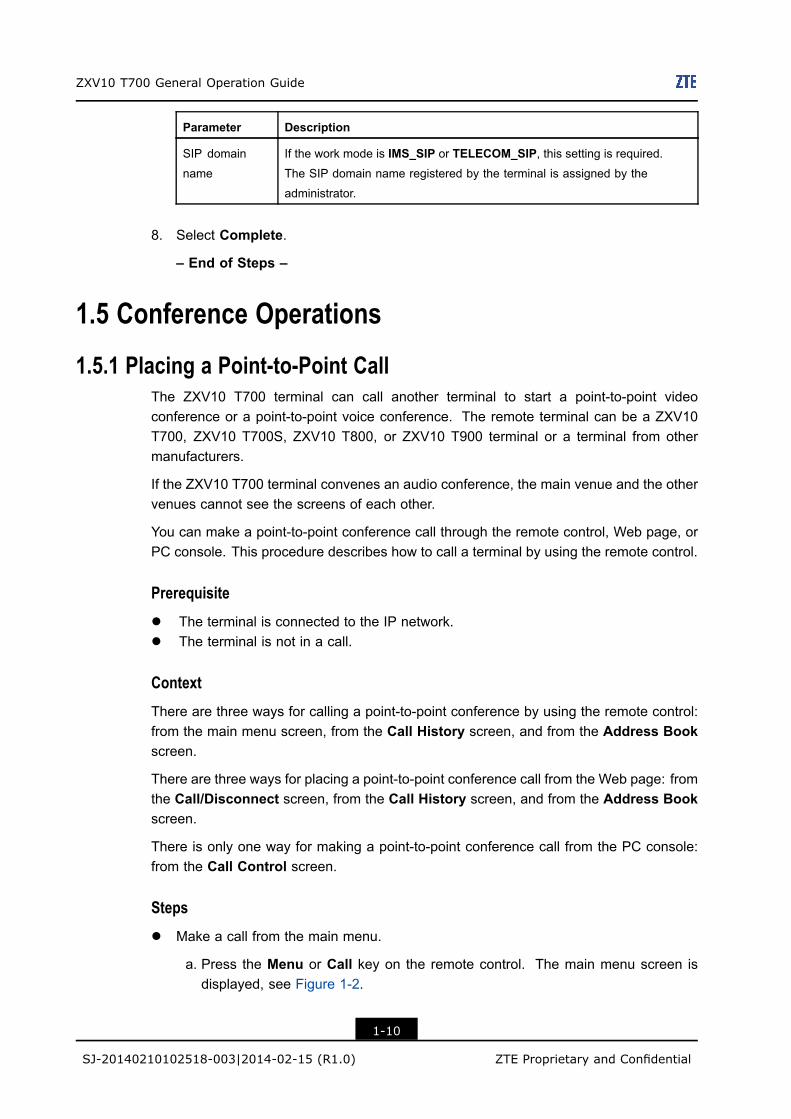
Parameter Description
SIP domain
name
If the work mode is IMS_SIP or TELECOM_SIP, this setting is required.The SIP domain name registered by the terminal is assigned by the
administrator.
8. Select Complete.
– End of Steps –
1.5 Conference Operations
1.5.1 Placing a Point-to-Point CallThe ZXV10 T700 terminal can call another terminal to start a point-to-point videoconference or a point-to-point voice conference. The remote terminal can be a ZXV10T700, ZXV10 T700S, ZXV10 T800, or ZXV10 T900 terminal or a terminal from othermanufacturers.
If the ZXV10 T700 terminal convenes an audio conference, the main venue and the othervenues cannot see the screens of each other.
You can make a point-to-point conference call through the remote control, Web page, orPC console. This procedure describes how to call a terminal by using the remote control.
Prerequisitel The terminal is connected to the IP network.l The terminal is not in a call.
ContextThere are three ways for calling a point-to-point conference by using the remote control:from the main menu screen, from the Call History screen, and from the Address Bookscreen.
There are three ways for placing a point-to-point conference call from the Web page: fromthe Call/Disconnect screen, from the Call History screen, and from the Address Bookscreen.
There is only one way for making a point-to-point conference call from the PC console:from the Call Control screen.
Stepsl Make a call from the main menu.
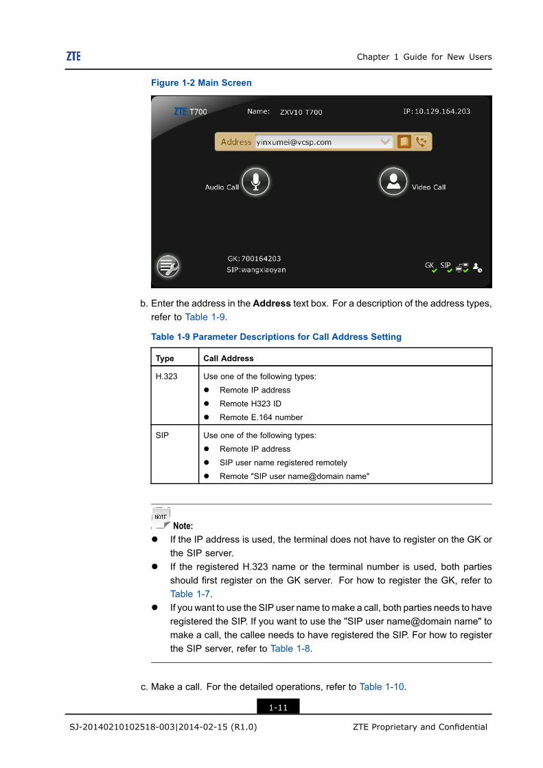
a. Press the Menu or Call key on the remote control. The main menu screen isdisplayed, see Figure 1-2.
1-10
SJ-20140210102518-003|2014-02-15 (R1.0) ZTE Proprietary and Confidential
Chapter 1 Guide for New Users
Figure 1-2 Main Screen
b. Enter the address in the Address text box. For a description of the address types,refer to Table 1-9.
Table 1-9 Parameter Descriptions for Call Address Setting
Type Call Address
H.323 Use one of the following types:
l Remote IP address
l Remote H323 ID
l Remote E.164 number
SIP Use one of the following types:
l Remote IP address
l SIP user name registered remotely
l Remote "SIP user name@domain name"
Note:l If the IP address is used, the terminal does not have to register on the GK or
the SIP server.l If the registered H.323 name or the terminal number is used, both parties
should first register on the GK server. For how to register the GK, refer toTable 1-7.
l If you want to use the SIP user name tomake a call, both parties needs to haveregistered the SIP. If you want to use the "SIP user name@domain name" tomake a call, the callee needs to have registered the SIP. For how to registerthe SIP server, refer to Table 1-8.
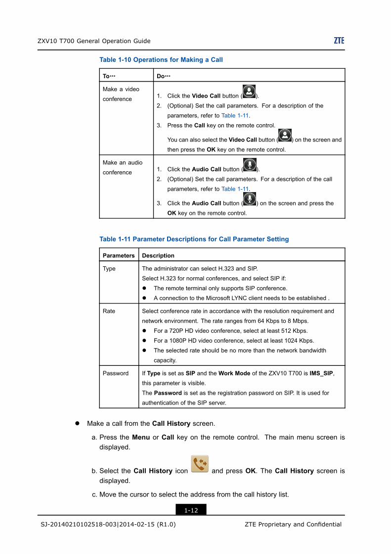
c. Make a call. For the detailed operations, refer to Table 1-10.
1-11
SJ-20140210102518-003|2014-02-15 (R1.0) ZTE Proprietary and Confidential
ZXV10 T700 General Operation Guide
Table 1-10 Operations for Making a Call
To……… Do………
Make a video
conference 1. Click the Video Call button ( ).
2. (Optional) Set the call parameters. For a description of the
parameters, refer to Table 1-11.
3. Press the Call key on the remote control.
You can also select the Video Call button ( ) on the screen and
then press the OK key on the remote control.
Make an audio
conference 1. Click the Audio Call button ( ).
2. (Optional) Set the call parameters. For a description of the call
parameters, refer to Table 1-11.
3. Click the Audio Call button ( ) on the screen and press the
OK key on the remote control.
Table 1-11 Parameter Descriptions for Call Parameter Setting
Parameters Description
Type The administrator can select H.323 and SIP.
Select H.323 for normal conferences, and select SIP if:
l The remote terminal only supports SIP conference.
l A connection to the Microsoft LYNC client needs to be established .
Rate Select conference rate in accordance with the resolution requirement and
network environment. The rate ranges from 64 Kbps to 8 Mbps.
l For a 720P HD video conference, select at least 512 Kbps.
l For a 1080P HD video conference, select at least 1024 Kbps.
l The selected rate should be no more than the network bandwidth
capacity.
Password If Type is set as SIP and the Work Mode of the ZXV10 T700 is IMS_SIP,this parameter is visible.
The Password is set as the registration password on SIP. It is used for
authentication of the SIP server.
l Make a call from the Call History screen.
a. Press the Menu or Call key on the remote control. The main menu screen isdisplayed.
b. Select the Call History icon and press OK. The Call History screen isdisplayed.
c. Move the cursor to select the address from the call history list.
1-12
SJ-20140210102518-003|2014-02-15 (R1.0) ZTE Proprietary and Confidential
Chapter 1 Guide for New Users
d. Press Call on the remote control, and then make a call to the selected record.
l Make a call from the Address Book screen.
a. Press the Directory key on the remote control or select the Address Book icon
from the main menu screen. The Address Book screen is displayed.
b. Perform the corresponding operations as needed. For the detailed operations,refer to Table 1-12.
Table 1-12 Operations for Calling a Terminal From the Address Book Screen
To……… Do………
Make a call
from the local
address book
1. Select Local from the drop-down list on the Address Book screen.2. Select a contact from the contact list.
3. Press Call on the remote control to start a call to the selected address.
Make a call
from the LDAP
address book
1. Select From LDAP Server from the drop-down list on the AddressBook screen.
2. Search for and select a contact to be called.
3. Press OK on the remote control. The Information of contactorscreen is displayed.
4. Press Call on the remote control to start a call.You can also select Call, and then press OK to start a call.
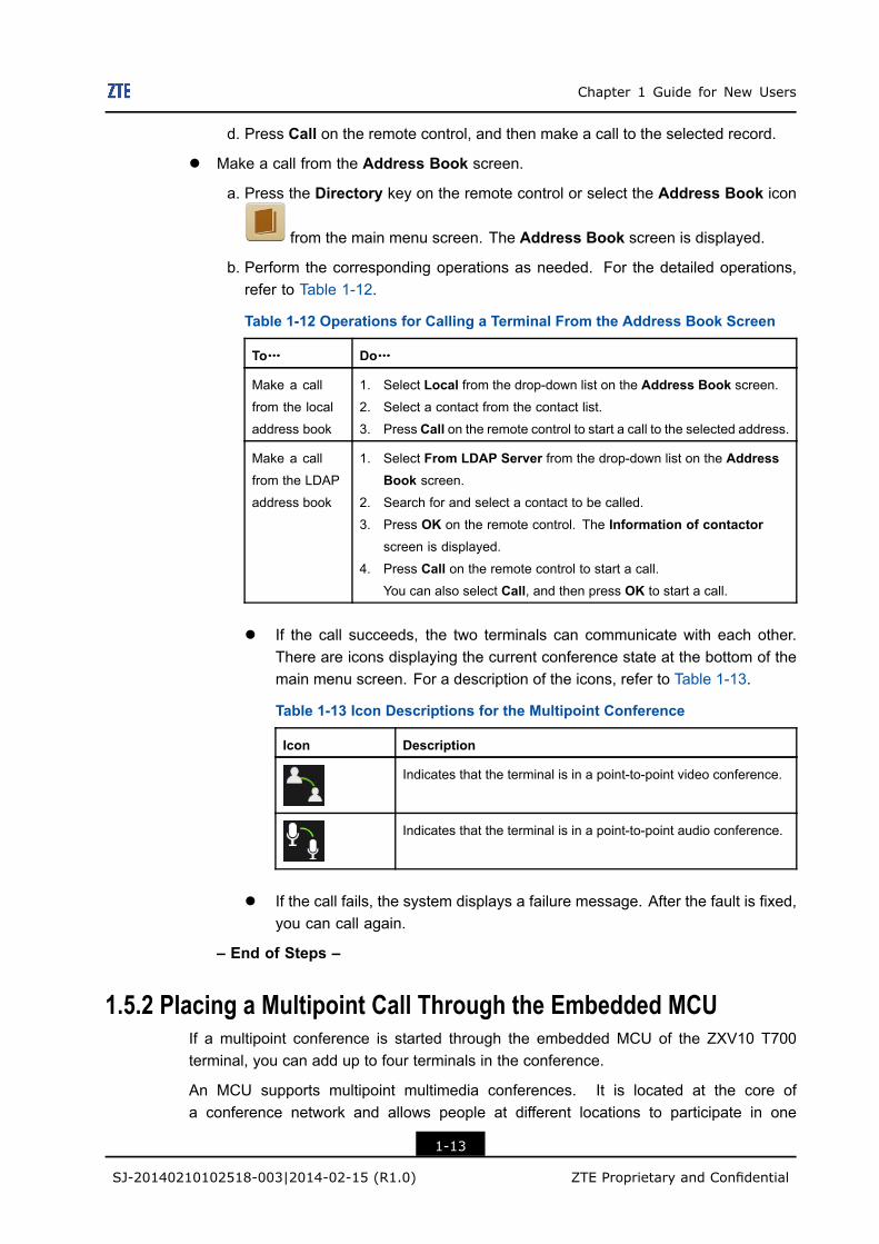
l If the call succeeds, the two terminals can communicate with each other.There are icons displaying the current conference state at the bottom of themain menu screen. For a description of the icons, refer to Table 1-13.
Table 1-13 Icon Descriptions for the Multipoint Conference
Icon Description
Indicates that the terminal is in a point-to-point video conference.
Indicates that the terminal is in a point-to-point audio conference.
l If the call fails, the system displays a failure message. After the fault is fixed,you can call again.
– End of Steps –
1.5.2 Placing a Multipoint Call Through the Embedded MCUIf a multipoint conference is started through the embedded MCU of the ZXV10 T700terminal, you can add up to four terminals in the conference.
An MCU supports multipoint multimedia conferences. It is located at the core ofa conference network and allows people at different locations to participate in one
1-13
SJ-20140210102518-003|2014-02-15 (R1.0) ZTE Proprietary and Confidential
ZXV10 T700 General Operation Guide
conference. The MCU supports mixing and switching digital signals, including audio,video, data, and signaling without affecting their qualities. It provides audio mixing, videoswitching, and multipoint communication protocol processing.
You can start an embedded MCU multipoint conference through the remote control, Webpage, or PC console. This procedure describes how to use the remote control.
Prerequisitel The ZXV10 T700 terminal supports the embedded MCU function.l The terminal is connected to the IP network.l The terminal is not in a call.
Contextl The MCU server is not involved in a multipoint conference started through the
embedded ZXV10 T700 MCU.l If a multipoint conference is initiated through the embedded MCU of the ZXV10 T700
terminal, the maximum number of participating terminals is five (including the hostingZXV10 T700 itself).
The local terminal supports the embedded MCU function. To check whether the localterminal supports the embedded MCU function, perform either of the following:
l Select > System > Maintenance > License with the remote control.l Select System > License on the Web page.
The following methods can be used to start a multipoint conference through the embeddedMCU.l Three ways using the remote control: make a call from the main menu screen, the
Call History screen, or the Address Book screen.l Three ways using the web page: make a call from the Call/Disconnect page, the Call
History page, or the Address Book page.l One way using the PC console: make a call from the Call Control page.
Steps1. Call terminals to participate in the conference one by one. For details, refer to 1.5.1
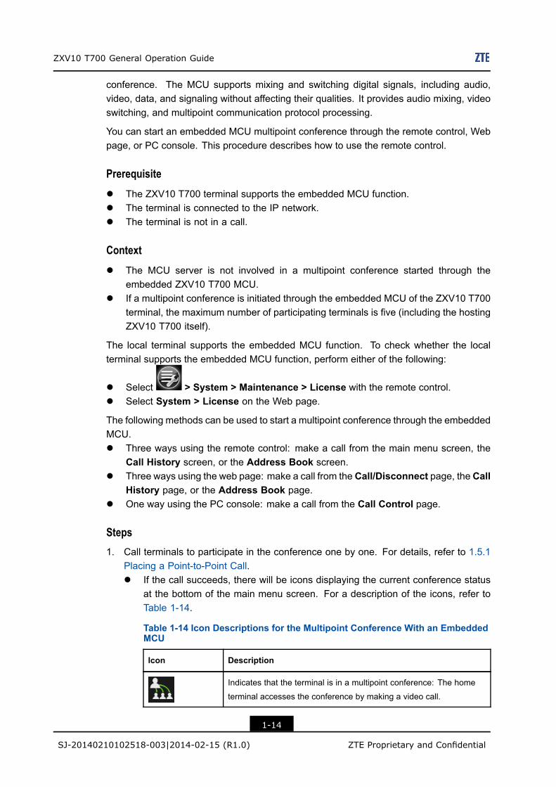
Placing a Point-to-Point Call.l If the call succeeds, there will be icons displaying the current conference status
at the bottom of the main menu screen. For a description of the icons, refer toTable 1-14.
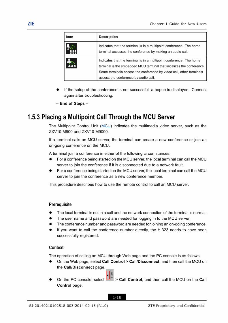
Table 1-14 Icon Descriptions for the Multipoint Conference With an EmbeddedMCU
Icon Description
Indicates that the terminal is in a multipoint conference: The home
terminal accesses the conference by making a video call.
1-14
SJ-20140210102518-003|2014-02-15 (R1.0) ZTE Proprietary and Confidential
Chapter 1 Guide for New Users
Icon Description
Indicates that the terminal is in a multipoint conference: The home
terminal accesses the conference by making an audio call.
Indicates that the terminal is in a multipoint conference: The home
terminal is the embedded MCU terminal that initializes the conference.
Some terminals access the conference by video call, other terminals
access the conference by audio call.
l If the setup of the conference is not successful, a popup is displayed. Connectagain after troubleshooting.
– End of Steps –
1.5.3 Placing a Multipoint Call Through the MCU ServerThe Multipoint Control Unit (MCU) indicates the multimedia video server, such as theZXV10 M900 and ZXV10 M9000.
If a terminal calls an MCU server, the terminal can create a new conference or join anon-going conference on the MCU.
A terminal join a conference in either of the following circumstances.l For a conference being started on the MCU server, the local terminal can call the MCU
server to join the conference if it is disconnected due to a network fault.l For a conference being started on the MCU server, the local terminal can call the MCU
server to join the conference as a new conference member.
This procedure describes how to use the remote control to call an MCU server.
Prerequisitel The local terminal is not in a call and the network connection of the terminal is normal.l The user name and password are needed for logging in to the MCU server.l The conference number and password are needed for joining an on-going conference.l If you want to call the conference number directly, the H.323 needs to have been
successfully registered.
ContextThe operation of calling an MCU through Web page and the PC console is as follows:l On the Web page, select Call Control > Call/Disconnect, and then call the MCU on
the Call/Disconnect page.
l On the PC console, select > Call Control, and then call the MCU on the CallControl page.
1-15
SJ-20140210102518-003|2014-02-15 (R1.0) ZTE Proprietary and Confidential
ZXV10 T700 General Operation Guide
Steps1. Press theCall orMenu key on the remote control. Themain menu screen is displayed.
2. Set Address. The value can be:l Special service number of the conference, for example, 196 (ZXV10 M900)l IP address of the MCUl MCU number (MCU supports calling through MCU number)l Conference number
3. Refer to 1.5.1 Placing a Point-to-Point Call to perform the corresponding operations tomake a call.
4. If the call wizard is displayed, follow the instructions of the wizard to start the call.l If the call is successful, the local terminal is added in the conference.l If the call fails, the system displays a failure message. After the fault is fixed, call
again.
– End of Steps –
1.5.4 Placing a Multipoint Audio Call Without an MCUThe ZXV10 T700 supports calling up to four terminals without using the built-in MCU or theMCU server to start a small multiple-point conference. Among the four called terminals,only one supports video calling and the others support audio calling.
Prerequisitel The terminal is connected to the IP network.l The terminal is not in a call.
Steps1. Call the terminals one by one. For detailed operations, refer to 1.5.1 Placing a
Point-to-Point Call.
– End of Steps –
1.5.5 Calling the Microsoft Lync AccountThe ZXV10 T700 supports point-to-point communication with a Microsoft Lync terminal:l The ZXV10 T700 can make a voice call or video call to the Microsoft Lync 2010.l The ZXV10 T700 can make a voice call to the Microsoft Lync 2013.
You can call a Microsoft Lync terminal through the remote control, Web page, or PCconsole. This procedure describes how to call a terminal by using the remote control.
Prerequisitel The ZXV10 T700 terminal is not in a call.l The ZXV10 T700 terminal is connected to the IP network.l TheMicrosoft Lync account is registered, and the account information is remembered.
1-16
SJ-20140210102518-003|2014-02-15 (R1.0) ZTE Proprietary and Confidential
Chapter 1 Guide for New Users
Steps1. Specify the SIP configuration.
a. Select > System > SIP. The SIP Settings screen is displayed.
b. Set the parameters in accordance with the Microsoft Lync account information.For a description of the parameters, refer to Table 1-15.
Table 1-15 Parameter Descriptions for SIP Configuration
Parameter Description
Work Mode Select MICROSOFT_LYNC.
User Name User name registered in the Microsoft Lync server.
Transport Protocol Select TLS.Use the Transport Layer Security (TLS). The terminal verifies that
the SIP server is a trusted server.
Proxy Server Addr. Microsoft Lync proxy server address.
SIP Register Select Enable.
Register Server
Addr.
Microsoft Lync registration server address.
Authenticate Name Complete the user name registered on the Microsoft Lync server, for
example, [email protected].
Password Password to log in to the Microsoft Lync server.
2. Perform the corresponding operations to make a call. For the detailed operations,refer to Table 1-16.
Table 1-16 Operations for Calling the Microsoft Lync
To……… Do………
Use the ZXV10 T700
to call a Microsoft
Lync account
i. Press the Menu or Call key on the remote control. The main menu
screen is displayed.
ii. Enter the other party’s Microsoft Lync user name (including domain
name) in the Address text box, for example, [email protected].
iii. Select Video Call or Audio Call.
iv. Select SIP from the Call Type list, and select a calling rate from the
Call Rate list.
v. Press the Call key on the remote control to start the call.
1-17
SJ-20140210102518-003|2014-02-15 (R1.0) ZTE Proprietary and Confidential
ZXV10 T700 General Operation Guide
To……… Do………
Use the Microsoft
Lync client to call the
ZXV10 T700
Log in to the Microsoft Lync account, and use the full user name in Table
1-15 (including the domain name, for example, [email protected])
to make a call.
– End of Steps –
1.5.6 Disconnecting a Calll For a point-to-point conference, any party in the conference can disconnect the call.l For a multipoint conference through the embedded MCU, the disconnecting opera-
tions are as follows:
à The terminal acting as MCU can disconnect all the terminals or some terminals.
à The chairman can end the conference.
à An ordinary terminal can only disconnect from a MCU terminal. Only the ordinaryterminal itself can disconnect from the conference.
The conference can be called and disconnected with the remote control, Web page, or PCconsole. This procedure describes how to disconnect the conference by using the remotecontrol.
PrerequisiteThe terminal is in a call.
ContextThe related operations on the Web page and PC console are as follows:
l Log in to the Web page. Select Call Control > Call/Disconnect. TheCall/Disconnect page is displayed. Click the Disconnect button next to the terminalto be disconnected.
l Log in to the PC console. Select > Call Control. The Call Control page isdisplayed. Select the terminal to be disconnected. Click the Disconnect button.
Steps1. Perform the corresponding operations to disconnect a call. For the detailed operations,
refer to Table 1-17 .
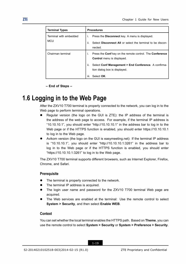
Table 1-17 Operations for Disconnecting a Call
Terminal Types Procedures
Ordinary terminal i. Press the Disconnect key on the remote control. A dialog
box is displayed.
ii. Select OK.
1-18
SJ-20140210102518-003|2014-02-15 (R1.0) ZTE Proprietary and Confidential
Chapter 1 Guide for New Users
Terminal Types Procedures
Terminal with embedded
MCU
i. Press the Disconnect key. A menu is displayed.
ii. Select Disconnect All or select the terminal to be discon-
nected.
Chairman terminal i. Press the Conf key on the remote control. The ConferenceControl menu is displayed.
ii. Select Conf Management > End Conference. A confirma-
tion dialog box is displayed.
iii. Select OK.
– End of Steps –
1.6 Logging in to the Web PageAfter the ZXV10 T700 terminal is properly connected to the network, you can log in to theWeb page to perform terminal operations.l Regular version (the logo on the GUI is ZTE): the IP address of the terminal is
the address of the web page to access. For example, if the terminal IP address is“10.10.10.1”, you should enter “http://10.10.10.1” in the address bar to log in to theWeb page or if the HTTPS function is enabled, you should enter https://10.10.10.1to log in to the Web page.
l Avikom version (the logo on the GUI is easymeeting.net): If the terminal IP addressis “10.10.10.1”, you should enter “http://10.10.10.1:3261” in the address bar tolog in to the Web page or if the HTTPS function is enabled, you should enter“https://10.10.10.1:3261” to log in to the Web page.
The ZXV10 T700 terminal supports different browsers, such as Internet Explorer, Firefox,Chrome, and Safari.
Prerequisitel The terminal is properly connected to the network.l The terminal IP address is acquired.l The login user name and password for the ZXV10 T700 terminal Web page are
acquired.l The Web services are enabled at the terminal: Use the remote control to select
System > Security, and then select Enable WEB.
ContextYou can set whether the local terminal enables the HTTPS path. Based on Theme, you canuse the remote control to select System > Security or System > Preference > Security.
1-19
SJ-20140210102518-003|2014-02-15 (R1.0) ZTE Proprietary and Confidential
ZXV10 T700 General Operation Guide
Steps1. In the address bar of the browser, enter the Web IP address of the terminal (for
example, http://10.10.10.1). The SYSTEM LOGIN page is displayed.
2. Select a language. In the upper-right corner of the SYSTEM LOGIN page, selectENGLISH.
3. Select admin or user from the LOGINNAME list, and enter a password in thePASSWORD box (the password is 111111 by default).l admin is for administrators who can modify and save the terminal configuration.l user is for common users who cannot modify the terminal configuration.
Note:
For security purposes, change the password once you log in to the Web page forthe first time. You can set the password by selecting User Management > UserInformation.
4. Click Login to log in to the terminal Web page.
– End of Steps –
1.7 Operating PC Console
1.7.1 Installing the PC ConsoleThe PC console is used to control the terminal and conference.
Different versions of terminal software have different versions of PC console. You candownload the proper version of the PC console by clicking the PC Console in the Webpage of this terminal.
Prerequisitel The ZXV10 T700 terminal is connected to the IP network.l The IP address of the ZXV10 T700 terminal is acquired.l The login user name and password of the ZXV10 T700 terminal are acquired.l The Web services are enabled at the terminal: Use the remote control to select
System > Security, and then select Enable WEB.
Steps1. Log in to the Web page, and click the PC Console. Then, you can perform either of
the following operations.l Click Save to save the installation file to your computer. Then, go to Step 2 to
continue the installation.
1-20
SJ-20140210102518-003|2014-02-15 (R1.0) ZTE Proprietary and Confidential
Chapter 1 Guide for New Users
l Click Run, and click Run in the dialog box. Then, go to Step 3 to continue theinstallation.
2. Double-click the installation file.
3. Select English, and click OK. The PC console installation wizard is displayed.
4. Click Next to select the installation path in a dialog box.
The default installation path is C:\ZTE\PCconsole\T700.
5. Click the Browse... button to select the destination installation path of the PC console.
6. Click the Install button to start the installation process.
7. After the installation process is completed, a confirmation message box is displayed.
8. Click the Finish button.
– End of Steps –
1.7.2 Logging in to the PC ConsoleYou can control the terminal after you log in to the PC console successfully.
Prerequisitel The PC console software is installed on the computer.l The ZXV10 T700 terminal is connected to the IP network.l The IP address of the ZXV10 T700 terminal is acquired.l The login user name and password of the ZXV10 T700 terminal are acquired.l The PC console services are enabled at the terminal: Use the remote control to select
System > Security, and then select Enable PC Console.
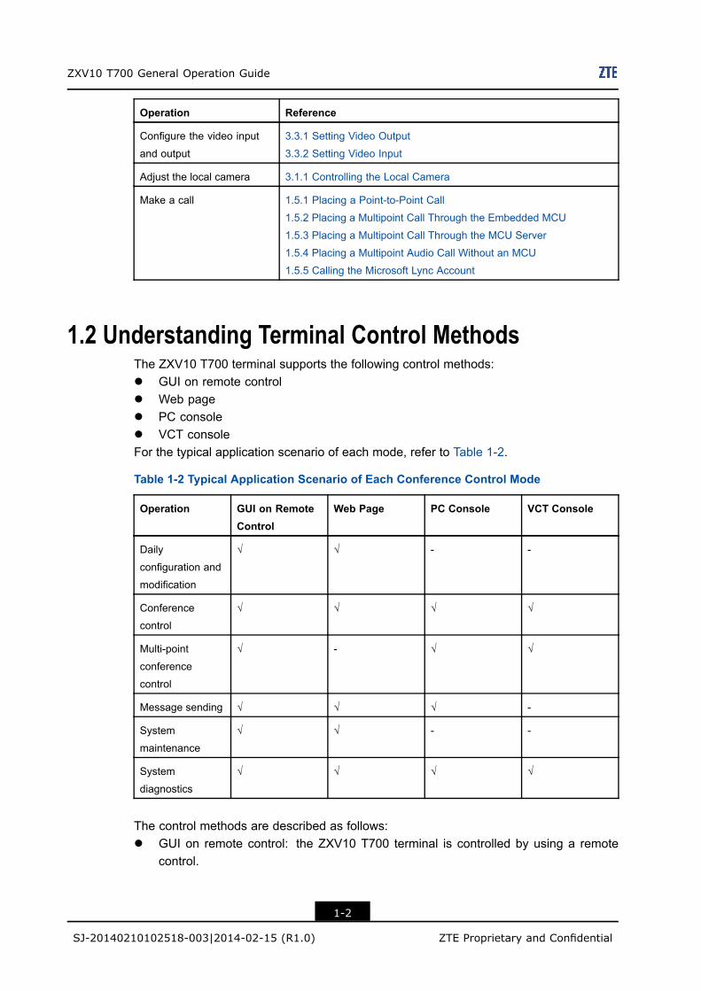
Steps1. On the desktop of your computer, select Start > All Programs > ZTE T Serial
Terminal Console > PC Console, or directly double-click the shortcut icon .The ZTE PC Console dialog box is displayed, see Figure 1-3.
1-21
SJ-20140210102518-003|2014-02-15 (R1.0) ZTE Proprietary and Confidential
ZXV10 T700 General Operation Guide
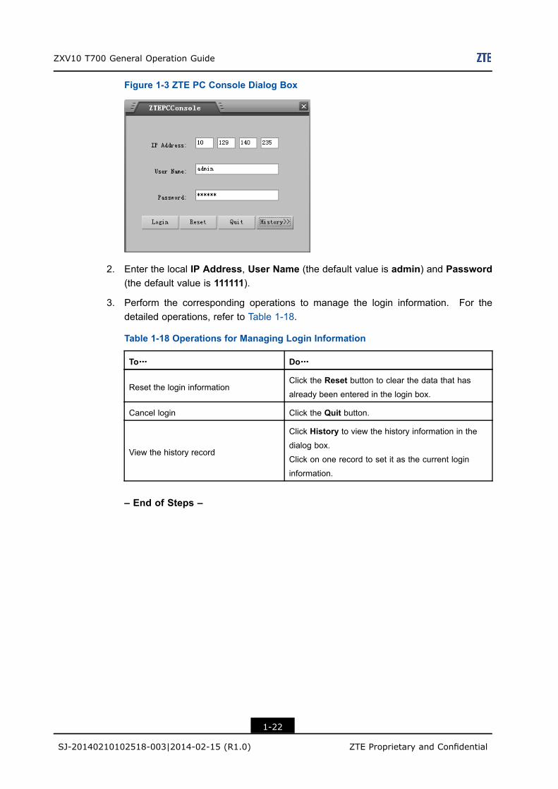
Figure 1-3 ZTE PC Console Dialog Box
2. Enter the local IP Address, User Name (the default value is admin) and Password(the default value is 111111).
3. Perform the corresponding operations to manage the login information. For thedetailed operations, refer to Table 1-18.
Table 1-18 Operations for Managing Login Information
To……… Do………
Reset the login informationClick the Reset button to clear the data that has
already been entered in the login box.
Cancel login Click the Quit button.
View the history record
Click History to view the history information in the
dialog box.
Click on one record to set it as the current login
information.
– End of Steps –
1-22
SJ-20140210102518-003|2014-02-15 (R1.0) ZTE Proprietary and Confidential
Chapter 2General Audio OperationsTable of Contents
Adjusting Output Volume ............................................................................................2-1Adjusting Input Volume...............................................................................................2-2
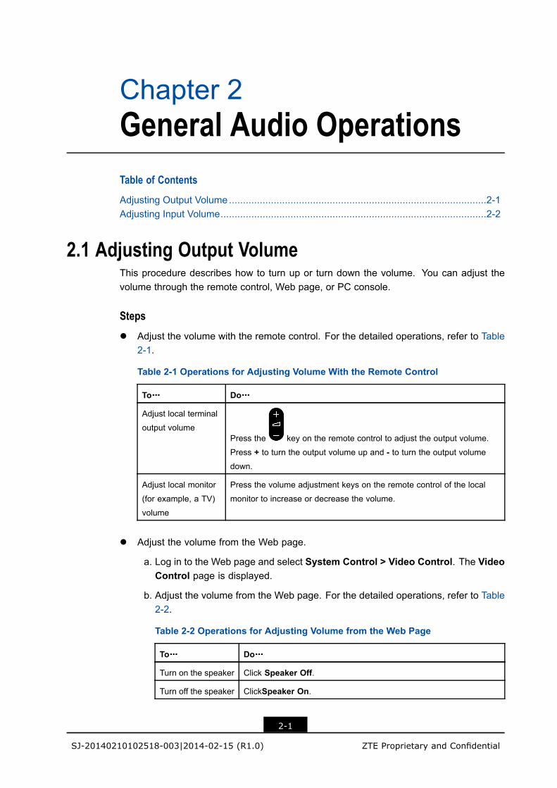
2.1 Adjusting Output VolumeThis procedure describes how to turn up or turn down the volume. You can adjust thevolume through the remote control, Web page, or PC console.
Stepsl Adjust the volume with the remote control. For the detailed operations, refer to Table
2-1.
Table 2-1 Operations for Adjusting Volume With the Remote Control
To……… Do………
Adjust local terminal
output volumePress the key on the remote control to adjust the output volume.
Press + to turn the output volume up and - to turn the output volumedown.
Adjust local monitor
(for example, a TV)
volume
Press the volume adjustment keys on the remote control of the local
monitor to increase or decrease the volume.
l Adjust the volume from the Web page.
a. Log in to the Web page and select System Control > Video Control. The VideoControl page is displayed.
b. Adjust the volume from the Web page. For the detailed operations, refer to Table2-2.
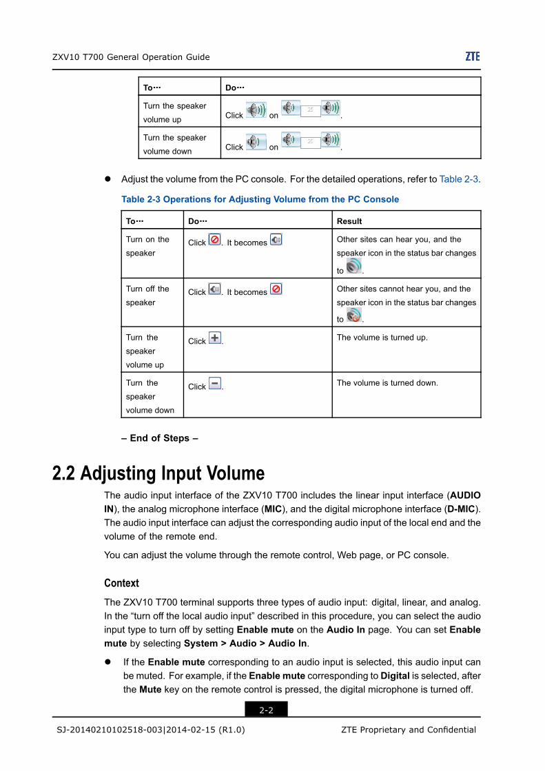
Table 2-2 Operations for Adjusting Volume from the Web Page
To……… Do………
Turn on the speaker Click Speaker Off.
Turn off the speaker ClickSpeaker On.
2-1
SJ-20140210102518-003|2014-02-15 (R1.0) ZTE Proprietary and Confidential
ZXV10 T700 General Operation Guide
To……… Do………
Turn the speaker
volume up Click on .
Turn the speaker
volume down Click on .
l Adjust the volume from the PC console. For the detailed operations, refer to Table 2-3.
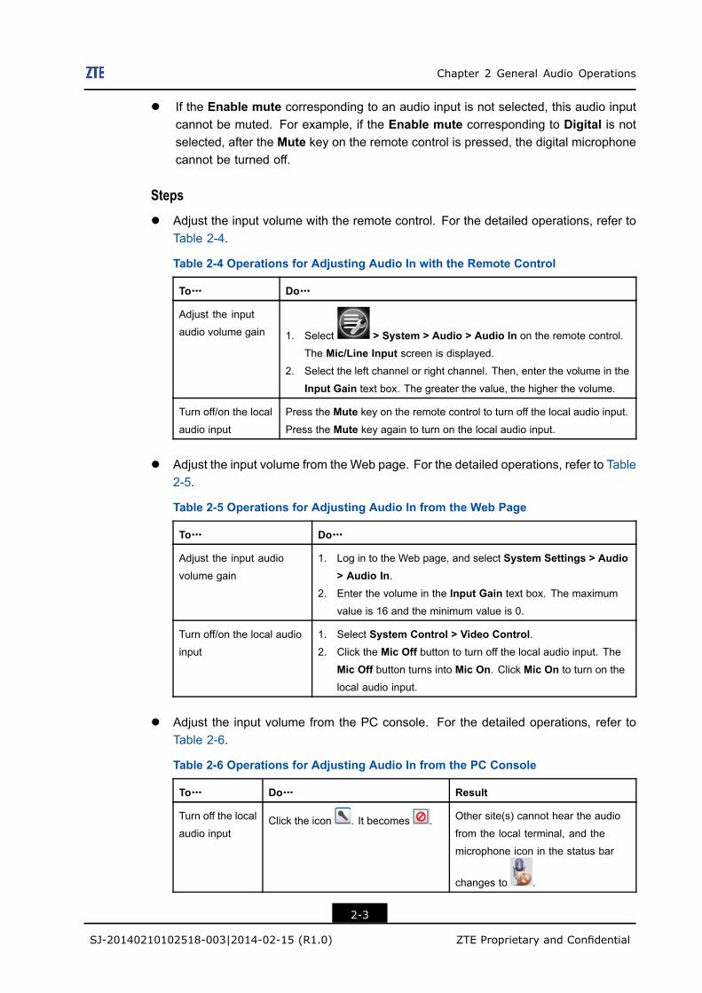
Table 2-3 Operations for Adjusting Volume from the PC Console
To……… Do……… Result
Turn on the
speakerClick . It becomes Other sites can hear you, and the
speaker icon in the status bar changes
to .
Turn off the
speakerClick . It becomes Other sites cannot hear you, and the
speaker icon in the status bar changes
to .
Turn the
speaker
volume up
Click . The volume is turned up.
Turn the
speaker
volume down
Click . The volume is turned down.
– End of Steps –
2.2 Adjusting Input VolumeThe audio input interface of the ZXV10 T700 includes the linear input interface (AUDIOIN), the analog microphone interface (MIC), and the digital microphone interface (D-MIC).The audio input interface can adjust the corresponding audio input of the local end and thevolume of the remote end.
You can adjust the volume through the remote control, Web page, or PC console.
ContextThe ZXV10 T700 terminal supports three types of audio input: digital, linear, and analog.In the “turn off the local audio input” described in this procedure, you can select the audioinput type to turn off by setting Enable mute on the Audio In page. You can set Enablemute by selecting System > Audio > Audio In.
l If the Enable mute corresponding to an audio input is selected, this audio input canbe muted. For example, if the Enable mute corresponding to Digital is selected, afterthe Mute key on the remote control is pressed, the digital microphone is turned off.
2-2
SJ-20140210102518-003|2014-02-15 (R1.0) ZTE Proprietary and Confidential
Chapter 2 General Audio Operations
l If the Enable mute corresponding to an audio input is not selected, this audio inputcannot be muted. For example, if the Enable mute corresponding to Digital is notselected, after the Mute key on the remote control is pressed, the digital microphonecannot be turned off.
Stepsl Adjust the input volume with the remote control. For the detailed operations, refer to
Table 2-4.
Table 2-4 Operations for Adjusting Audio In with the Remote Control
To……… Do………
Adjust the input
audio volume gain 1. Select > System > Audio > Audio In on the remote control.
The Mic/Line Input screen is displayed.2. Select the left channel or right channel. Then, enter the volume in the
Input Gain text box. The greater the value, the higher the volume.
Turn off/on the local
audio input
Press the Mute key on the remote control to turn off the local audio input.Press the Mute key again to turn on the local audio input.
l Adjust the input volume from the Web page. For the detailed operations, refer to Table2-5.
Table 2-5 Operations for Adjusting Audio In from the Web Page
To……… Do………
Adjust the input audio
volume gain
1. Log in to the Web page, and select System Settings > Audio> Audio In.
2. Enter the volume in the Input Gain text box. The maximum
value is 16 and the minimum value is 0.
Turn off/on the local audio
input
1. Select System Control > Video Control.2. Click the Mic Off button to turn off the local audio input. The
Mic Off button turns into Mic On. Click Mic On to turn on the
local audio input.
l Adjust the input volume from the PC console. For the detailed operations, refer toTable 2-6.
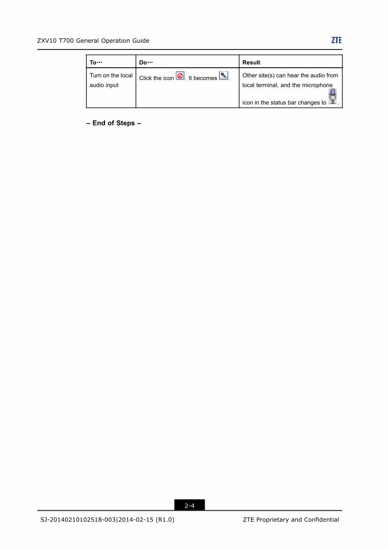
Table 2-6 Operations for Adjusting Audio In from the PC Console
To……… Do……… Result
Turn off the local
audio inputClick the icon . It becomes . Other site(s) cannot hear the audio
from the local terminal, and the
microphone icon in the status bar
changes to .
2-3
SJ-20140210102518-003|2014-02-15 (R1.0) ZTE Proprietary and Confidential
ZXV10 T700 General Operation Guide
To……… Do……… Result
Turn on the local
audio inputClick the icon . It becomes . Other site(s) can hear the audio from
local terminal, and the microphone
icon in the status bar changes to .
– End of Steps –
2-4
SJ-20140210102518-003|2014-02-15 (R1.0) ZTE Proprietary and Confidential
Chapter 3General Video OperationsTable of Contents
Operating Camera......................................................................................................3-1Operating Screen Display...........................................................................................3-9Setting Video............................................................................................................3-14
3.1 Operating Camera
3.1.1 Controlling the Local CameraIf the terminal is idle or in a conference, the position of the local camera can be adjusted.
The methods for adjusting the camera are as follows:l The camera can be adjusted by using the remote control.l The camera can be adjusted through the Video Control page of the Web page.l The camera can be adjusted in the video control area of the General Control screen
of the PC console.
Stepsl Adjust the camera by using the remote control.
a. On the remote control, press the Near/Far key. The icon is displayed onthe TV screen. Stop pressing the key and you can control the local camera.
b. Adjust the local camera. For the detailed operations, refer to Table 3-1.
Table 3-1 Operations for Adjusting the Local Camera with the Remote Control
To ……… Do ………
Adjust the camera angle On the remote control, press the up, down, left, and right
arrow keys.
Zoom the video in or out
On the remote control, press the key.
l Adjust the camera from the Web page.
a. On the Web page, select System Control > Video Control. The Video Controlpage is displayed.
3-1
SJ-20140210102518-003|2014-02-15 (R1.0) ZTE Proprietary and Confidential
ZXV10 T700 General Operation Guide
b. Select Local.
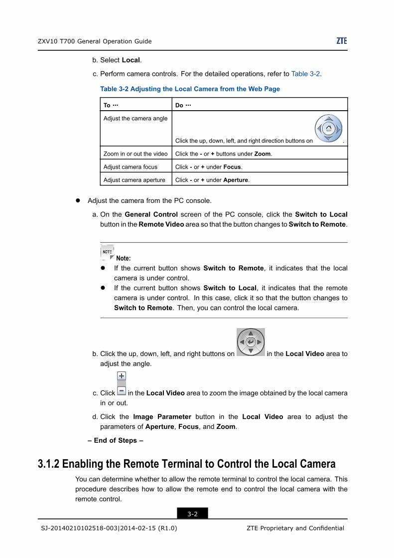
c. Perform camera controls. For the detailed operations, refer to Table 3-2.
Table 3-2 Adjusting the Local Camera from the Web Page
To ……… Do ………
Adjust the camera angle
Click the up, down, left, and right direction buttons on .
Zoom in or out the video Click the - or + buttons under Zoom.
Adjust camera focus Click - or + under Focus.
Adjust camera aperture Click - or + under Aperture.
l Adjust the camera from the PC console.
a. On the General Control screen of the PC console, click the Switch to Localbutton in theRemote Video area so that the button changes toSwitch to Remote.
Note:l If the current button shows Switch to Remote, it indicates that the local
camera is under control.l If the current button shows Switch to Local, it indicates that the remote
camera is under control. In this case, click it so that the button changes toSwitch to Remote. Then, you can control the local camera.
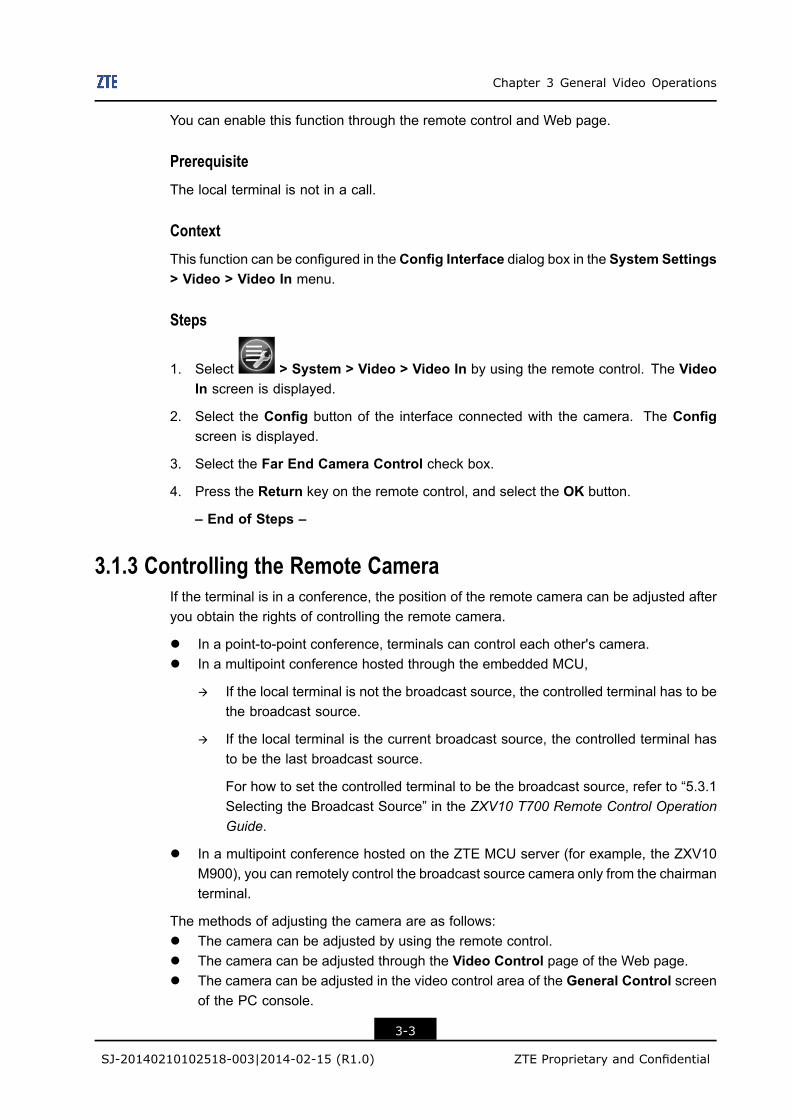
b. Click the up, down, left, and right buttons on in the Local Video area toadjust the angle.
c. Click in the Local Video area to zoom the image obtained by the local camerain or out.
d. Click the Image Parameter button in the Local Video area to adjust theparameters of Aperture, Focus, and Zoom.
– End of Steps –
3.1.2 Enabling the Remote Terminal to Control the Local CameraYou can determine whether to allow the remote terminal to control the local camera. Thisprocedure describes how to allow the remote end to control the local camera with theremote control.
3-2
SJ-20140210102518-003|2014-02-15 (R1.0) ZTE Proprietary and Confidential
Chapter 3 General Video Operations
You can enable this function through the remote control and Web page.
PrerequisiteThe local terminal is not in a call.
ContextThis function can be configured in the Config Interface dialog box in the System Settings> Video > Video In menu.
Steps
1. Select > System > Video > Video In by using the remote control. The VideoIn screen is displayed.
2. Select the Config button of the interface connected with the camera. The Configscreen is displayed.
3. Select the Far End Camera Control check box.
4. Press the Return key on the remote control, and select the OK button.
– End of Steps –
3.1.3 Controlling the Remote CameraIf the terminal is in a conference, the position of the remote camera can be adjusted afteryou obtain the rights of controlling the remote camera.
l In a point-to-point conference, terminals can control each other's camera.l In a multipoint conference hosted through the embedded MCU,
à If the local terminal is not the broadcast source, the controlled terminal has to bethe broadcast source.
à If the local terminal is the current broadcast source, the controlled terminal hasto be the last broadcast source.
For how to set the controlled terminal to be the broadcast source, refer to “5.3.1Selecting the Broadcast Source” in the ZXV10 T700 Remote Control OperationGuide.
l In a multipoint conference hosted on the ZTE MCU server (for example, the ZXV10M900), you can remotely control the broadcast source camera only from the chairmanterminal.
The methods of adjusting the camera are as follows:l The camera can be adjusted by using the remote control.l The camera can be adjusted through the Video Control page of the Web page.l The camera can be adjusted in the video control area of the General Control screen
of the PC console.
3-3
SJ-20140210102518-003|2014-02-15 (R1.0) ZTE Proprietary and Confidential
ZXV10 T700 General Operation Guide
PrerequisiteThe Far End Camera Control function is enabled on the controlled terminal. For thedetailed operations, refer to 3.1.2 Enabling the Remote Terminal to Control the LocalCamera.
Steps
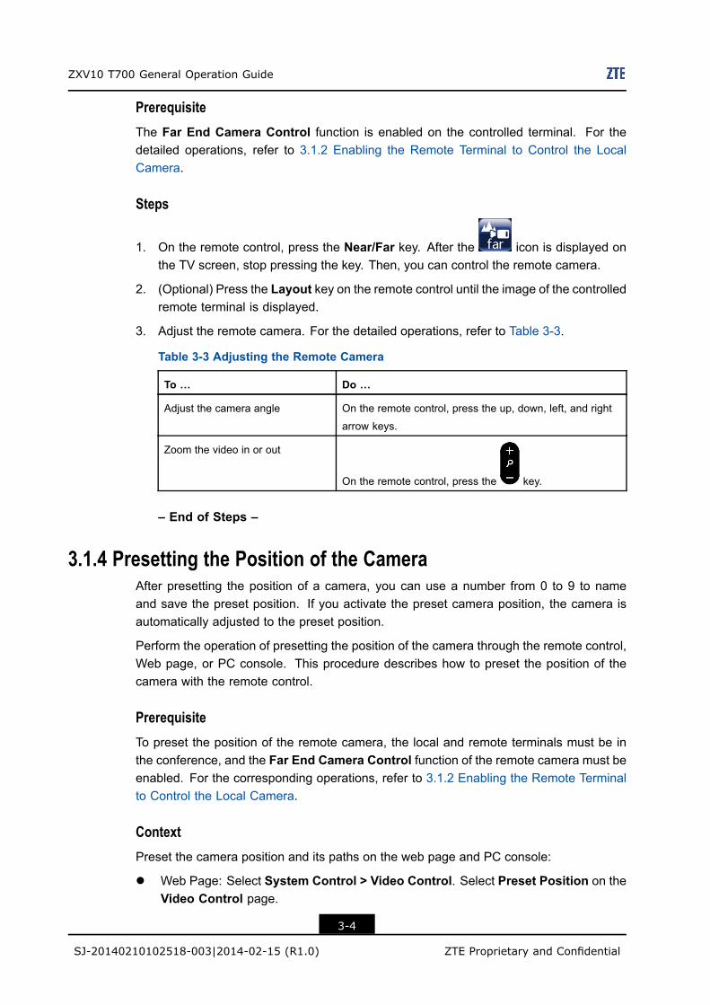
1. On the remote control, press the Near/Far key. After the icon is displayed onthe TV screen, stop pressing the key. Then, you can control the remote camera.
2. (Optional) Press the Layout key on the remote control until the image of the controlledremote terminal is displayed.
3. Adjust the remote camera. For the detailed operations, refer to Table 3-3.
Table 3-3 Adjusting the Remote Camera
To … Do …
Adjust the camera angle On the remote control, press the up, down, left, and right
arrow keys.
Zoom the video in or out
On the remote control, press the key.
– End of Steps –
3.1.4 Presetting the Position of the CameraAfter presetting the position of a camera, you can use a number from 0 to 9 to nameand save the preset position. If you activate the preset camera position, the camera isautomatically adjusted to the preset position.
Perform the operation of presetting the position of the camera through the remote control,Web page, or PC console. This procedure describes how to preset the position of thecamera with the remote control.
PrerequisiteTo preset the position of the remote camera, the local and remote terminals must be inthe conference, and the Far End Camera Control function of the remote camera must beenabled. For the corresponding operations, refer to 3.1.2 Enabling the Remote Terminalto Control the Local Camera.
ContextPreset the camera position and its paths on the web page and PC console:
l Web Page: Select System Control > Video Control. Select Preset Position on theVideo Control page.
3-4
SJ-20140210102518-003|2014-02-15 (R1.0) ZTE Proprietary and Confidential
Chapter 3 General Video Operations
l PC Console: On the Common Control page, click Preset Camera.
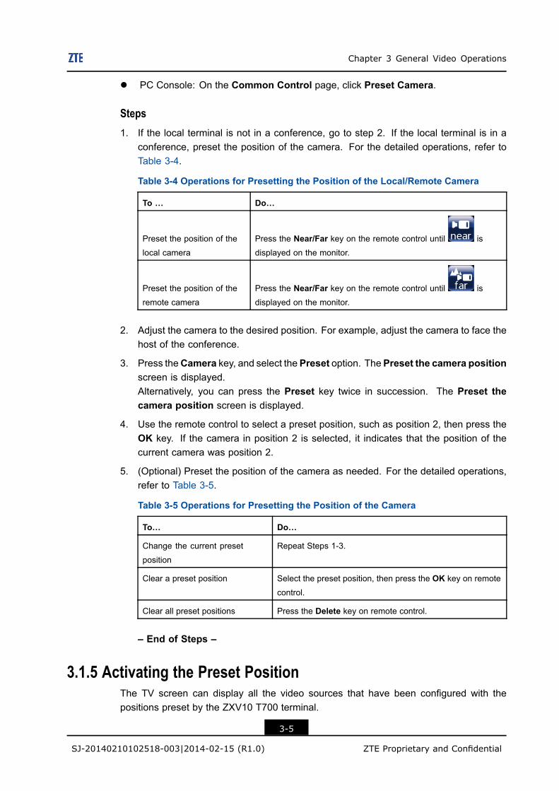
Steps1. If the local terminal is not in a conference, go to step 2. If the local terminal is in a
conference, preset the position of the camera. For the detailed operations, refer toTable 3-4.
Table 3-4 Operations for Presetting the Position of the Local/Remote Camera
To … Do…
Preset the position of the
local camera
Press the Near/Far key on the remote control until is
displayed on the monitor.
Preset the position of the
remote camera
Press the Near/Far key on the remote control until is
displayed on the monitor.
2. Adjust the camera to the desired position. For example, adjust the camera to face thehost of the conference.
3. Press theCamera key, and select thePreset option. ThePreset the camera positionscreen is displayed.Alternatively, you can press the Preset key twice in succession. The Preset thecamera position screen is displayed.
4. Use the remote control to select a preset position, such as position 2, then press theOK key. If the camera in position 2 is selected, it indicates that the position of thecurrent camera was position 2.
5. (Optional) Preset the position of the camera as needed. For the detailed operations,refer to Table 3-5.
Table 3-5 Operations for Presetting the Position of the Camera
To… Do…
Change the current preset
position
Repeat Steps 1-3.
Clear a preset position Select the preset position, then press the OK key on remote
control.
Clear all preset positions Press the Delete key on remote control.
– End of Steps –
3.1.5 Activating the Preset PositionThe TV screen can display all the video sources that have been configured with thepositions preset by the ZXV10 T700 terminal.
3-5
SJ-20140210102518-003|2014-02-15 (R1.0) ZTE Proprietary and Confidential
ZXV10 T700 General Operation Guide
After the preset positions are activated, the camera will automatically adjust to the presetdirection.
This procedure describes how to activate a preset position with the remote control.
Prerequisitel The camera position is set. For example, the camera has been preset to face the
conference chairman. For the corresponding operations, refer to 3.1.4 Presetting thePosition of the Camera.
l To activate the preset position of the remote camera, the local and remote terminalsmust be in the conference, and the Far End Camera Control function of the remotecamera must be enabled. For the corresponding operations, refer to 3.1.2 Enablingthe Remote Terminal to Control the Local Camera.
ContextYou can activate the preset position from the Web page or PC console. The procedure isas below.l Web Page: Select System Control > Video Control and select Activate Position
on the Video Control page.l PC Console: On the Common Control page, click Get Camera Position.
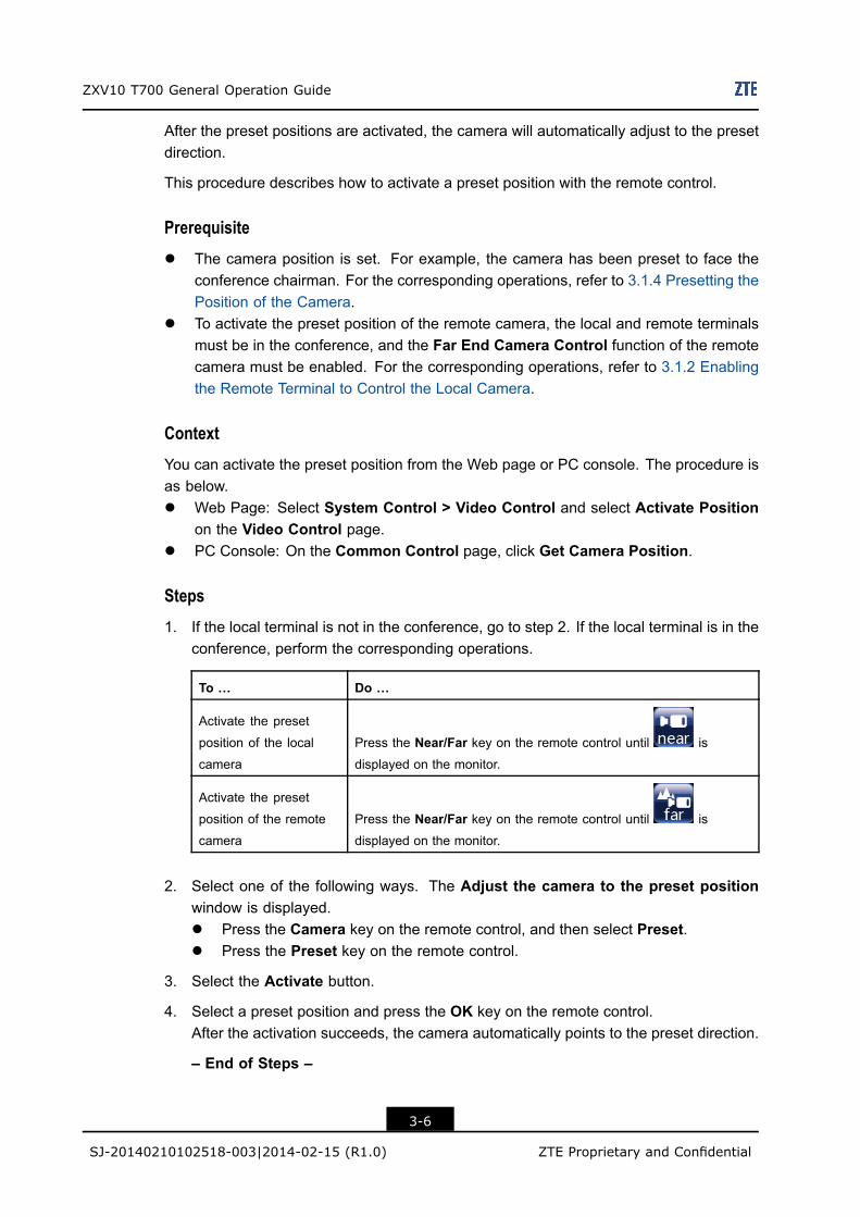
Steps1. If the local terminal is not in the conference, go to step 2. If the local terminal is in the
conference, perform the corresponding operations.
To … Do …
Activate the preset
position of the local
camera
Press the Near/Far key on the remote control until is
displayed on the monitor.
Activate the preset
position of the remote
camera
Press the Near/Far key on the remote control until is
displayed on the monitor.
2. Select one of the following ways. The Adjust the camera to the preset positionwindow is displayed.l Press the Camera key on the remote control, and then select Preset.l Press the Preset key on the remote control.
3. Select the Activate button.
4. Select a preset position and press the OK key on the remote control.After the activation succeeds, the camera automatically points to the preset direction.
– End of Steps –
3-6
SJ-20140210102518-003|2014-02-15 (R1.0) ZTE Proprietary and Confidential
Chapter 3 General Video Operations
3.1.6 Setting the CameraThis procedure describes how to set the parameters of the camera of the primary videosource. The new parameters of the camera take effect after they are set.l If you select Save, the new parameters of the camera will take effect after the terminal
will be restarted.
If you select Restore, the factory default settings are restored.
l If the Administrator Password function is enabled on the Security screen, you mustenter the administrator password before you can set the camera.
You can set the parameters through the remote control or the Web page. This proceduredescribes how to perform the operation with the remote control.
Context
To protect the parameters from being accidently modified, select > System >Security, check Enable Admin. Pwd., and enter the password in the AdministratorPwd. text box on the Security page.
Alternatively, you can log in to the Web page and click System Settings > Camera to setthe camera parameters.
Steps1. Press the Camera key on the remote control. The Set Video Source screen is
displayed.
2. Select Setting. The Setting screen is displayed.If the Please input administrator password dialog box is displayed after you pressCamera on the remote control, enter the correct password and selectOK. The Settingscreen is displayed.
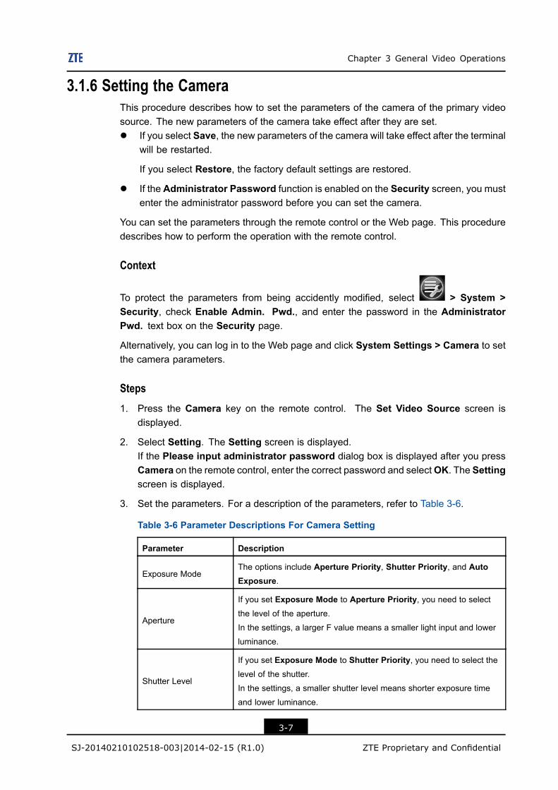
3. Set the parameters. For a description of the parameters, refer to Table 3-6.
Table 3-6 Parameter Descriptions For Camera Setting
Parameter Description
Exposure ModeThe options include Aperture Priority, Shutter Priority, and AutoExposure.
Aperture
If you set Exposure Mode to Aperture Priority, you need to selectthe level of the aperture.
In the settings, a larger F value means a smaller light input and lower
luminance.
Shutter Level
If you set Exposure Mode to Shutter Priority, you need to select thelevel of the shutter.
In the settings, a smaller shutter level means shorter exposure time
and lower luminance.
3-7
SJ-20140210102518-003|2014-02-15 (R1.0) ZTE Proprietary and Confidential
ZXV10 T700 General Operation Guide
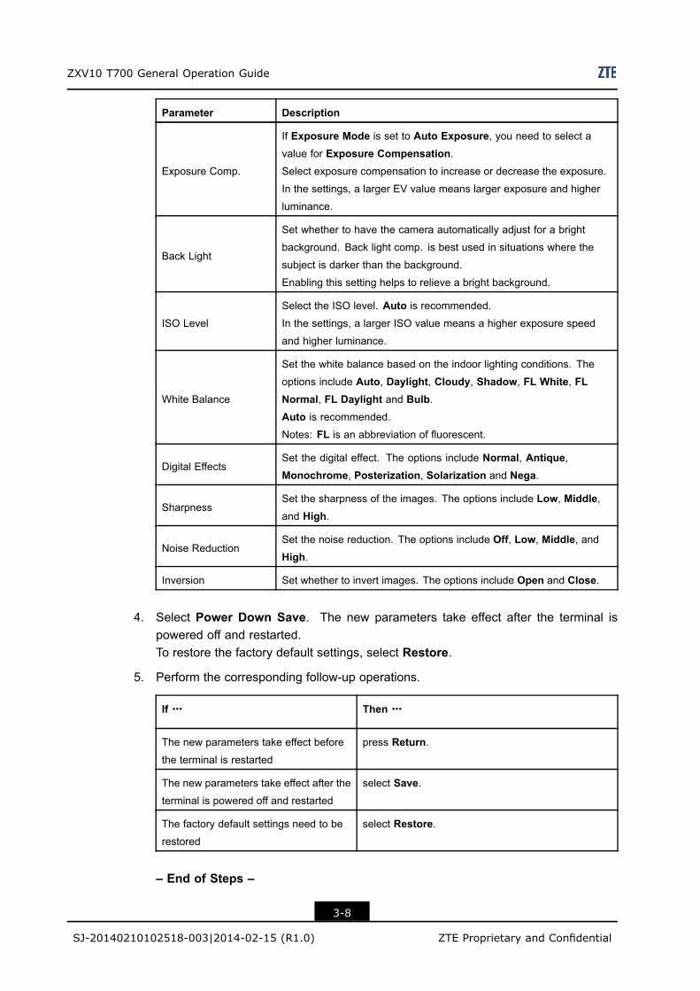
Parameter Description
Exposure Comp.
If Exposure Mode is set to Auto Exposure, you need to select avalue for Exposure Compensation.Select exposure compensation to increase or decrease the exposure.
In the settings, a larger EV value means larger exposure and higher
luminance.
Back Light
Set whether to have the camera automatically adjust for a bright
background. Back light comp. is best used in situations where the
subject is darker than the background.
Enabling this setting helps to relieve a bright background.
ISO Level
Select the ISO level. Auto is recommended.
In the settings, a larger ISO value means a higher exposure speed
and higher luminance.
White Balance
Set the white balance based on the indoor lighting conditions. The
options include Auto, Daylight, Cloudy, Shadow, FL White, FLNormal, FL Daylight and Bulb.Auto is recommended.
Notes: FL is an abbreviation of fluorescent.
Digital EffectsSet the digital effect. The options include Normal, Antique,Monochrome, Posterization, Solarization and Nega.
SharpnessSet the sharpness of the images. The options include Low, Middle,and High.
Noise ReductionSet the noise reduction. The options include Off, Low, Middle, andHigh.
Inversion Set whether to invert images. The options include Open and Close.
4. Select Power Down Save. The new parameters take effect after the terminal ispowered off and restarted.To restore the factory default settings, select Restore.
5. Perform the corresponding follow-up operations.
If ……… Then ………
The new parameters take effect before
the terminal is restarted
press Return.
The new parameters take effect after the
terminal is powered off and restarted
select Save.
The factory default settings need to be
restored
select Restore.
– End of Steps –
3-8
SJ-20140210102518-003|2014-02-15 (R1.0) ZTE Proprietary and Confidential
Chapter 3 General Video Operations
3.2 Operating Screen Display
3.2.1 Adjusting Display ModeThe available display modes are determined by the Display Mode configuration of VideoOutput.
PrerequisiteOn the page where the first Video Output line’s Display Mode is set, a display mode isselected. (You can select System > Video > Video Output).
Stepsl Press the Layout key on the remote control repeatedly to view the modes.l After logging into the Web page, click the Change Display Mode button repeatedly to
view and select a mode.l After logging into the PC console, click the Display Mode button repeatedly to view
and select a mode.
– End of Steps –
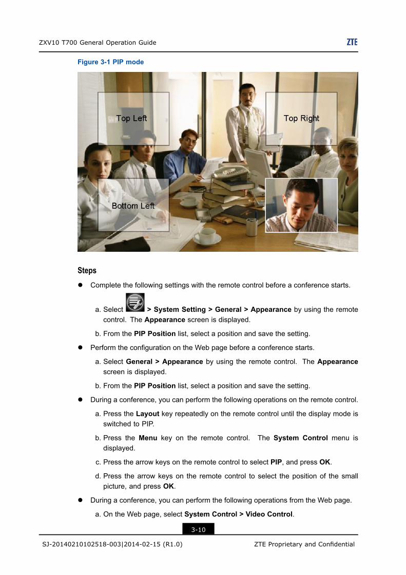
3.2.2 Adjusting the Position of Picture-in-PictureIn Picture-in-Picture (PIP) mode, you can set a small picture on the screen.
You can adjust the position of picture-in-picture through the remote control and Web page.
ContextIn Picture-in-Picture (PIP) mode, you can set the position of the small picture on the screen.The position can be the top left, top right, bottom left, or bottom right corner.
3-9
SJ-20140210102518-003|2014-02-15 (R1.0) ZTE Proprietary and Confidential
ZXV10 T700 General Operation Guide
Figure 3-1 PIP mode
Stepsl Complete the following settings with the remote control before a conference starts.
a. Select > System Setting > General > Appearance by using the remotecontrol. The Appearance screen is displayed.
b. From the PIP Position list, select a position and save the setting.
l Perform the configuration on the Web page before a conference starts.
a. Select General > Appearance by using the remote control. The Appearancescreen is displayed.
b. From the PIP Position list, select a position and save the setting.
l During a conference, you can perform the following operations on the remote control.
a. Press the Layout key repeatedly on the remote control until the display mode isswitched to PIP.
b. Press the Menu key on the remote control. The System Control menu isdisplayed.
c. Press the arrow keys on the remote control to select PIP, and press OK.
d. Press the arrow keys on the remote control to select the position of the smallpicture, and press OK.
l During a conference, you can perform the following operations from the Web page.
a. On the Web page, select System Control > Video Control.
3-10
SJ-20140210102518-003|2014-02-15 (R1.0) ZTE Proprietary and Confidential
Chapter 3 General Video Operations
b. Click the Change Display Mode button continuously until the display mode isswitched to PIP.
c. Click PIP Position.
d. Click the position.
– End of Steps –
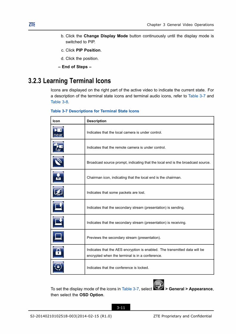
3.2.3 Learning Terminal IconsIcons are displayed on the right part of the active video to indicate the current state. Fora description of the terminal state icons and terminal audio icons, refer to Table 3-7 andTable 3-8.
Table 3-7 Descriptions for Terminal State Icons
Icon Description
Indicates that the local camera is under control.
Indicates that the remote camera is under control.
Broadcast source prompt, indicating that the local end is the broadcast source.
Chairman icon, indicating that the local end is the chairman.
Indicates that some packets are lost.
Indicates that the secondary stream (presentation) is sending.
Indicates that the secondary stream (presentation) is receiving.
Previews the secondary stream (presentation).
Indicates that the AES encryption is enabled. The transmitted data will be
encrypted when the terminal is in a conference.
Indicates that the conference is locked.
To set the display mode of the icons in Table 3-7, select > General > Appearance,then select the OSD Option.
3-11
SJ-20140210102518-003|2014-02-15 (R1.0) ZTE Proprietary and Confidential
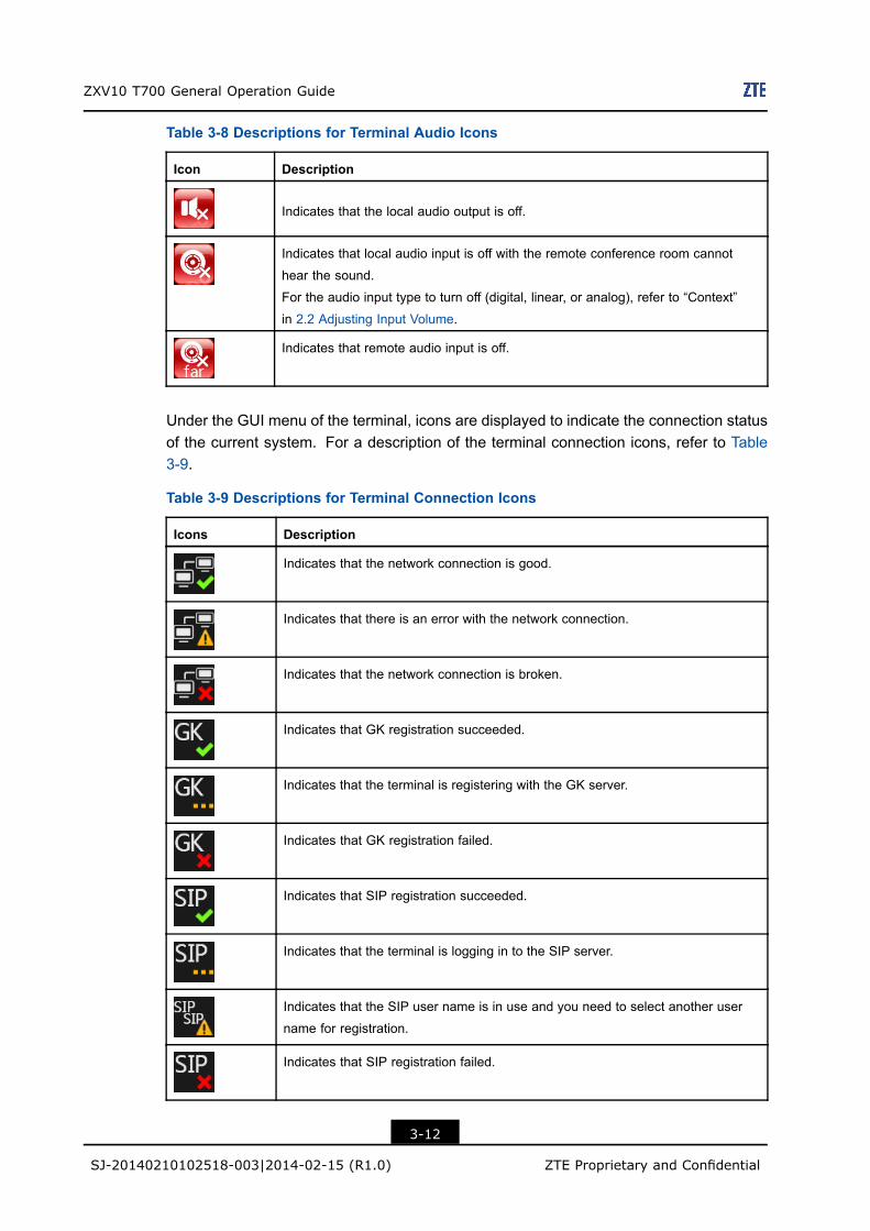
ZXV10 T700 General Operation Guide
Table 3-8 Descriptions for Terminal Audio Icons
Icon Description
Indicates that the local audio output is off.
Indicates that local audio input is off with the remote conference room cannot
hear the sound.
For the audio input type to turn off (digital, linear, or analog), refer to “Context”
in 2.2 Adjusting Input Volume.
Indicates that remote audio input is off.
Under the GUI menu of the terminal, icons are displayed to indicate the connection statusof the current system. For a description of the terminal connection icons, refer to Table3-9.
Table 3-9 Descriptions for Terminal Connection Icons
Icons Description
Indicates that the network connection is good.
Indicates that there is an error with the network connection.
Indicates that the network connection is broken.
Indicates that GK registration succeeded.
Indicates that the terminal is registering with the GK server.
Indicates that GK registration failed.
Indicates that SIP registration succeeded.
Indicates that the terminal is logging in to the SIP server.
Indicates that the SIP user name is in use and you need to select another user
name for registration.
Indicates that SIP registration failed.
3-12
SJ-20140210102518-003|2014-02-15 (R1.0) ZTE Proprietary and Confidential
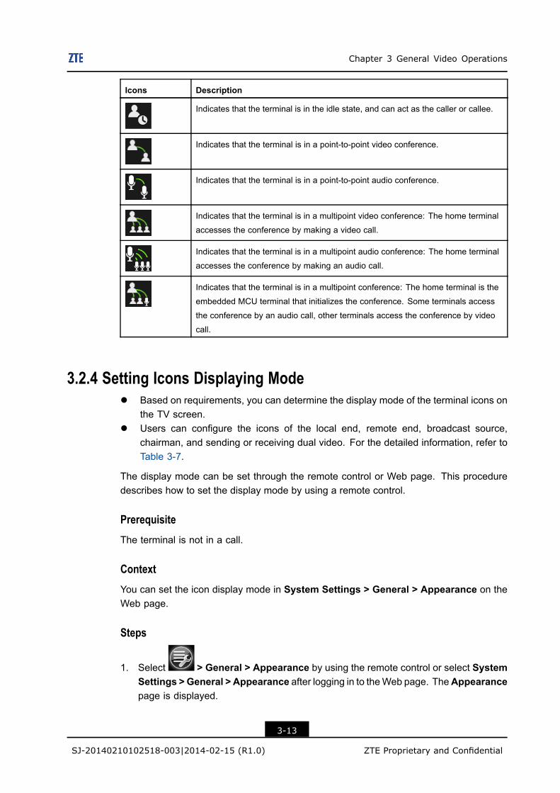
Chapter 3 General Video Operations
Icons Description
Indicates that the terminal is in the idle state, and can act as the caller or callee.
Indicates that the terminal is in a point-to-point video conference.
Indicates that the terminal is in a point-to-point audio conference.
Indicates that the terminal is in a multipoint video conference: The home terminal
accesses the conference by making a video call.
Indicates that the terminal is in a multipoint audio conference: The home terminal
accesses the conference by making an audio call.
Indicates that the terminal is in a multipoint conference: The home terminal is the
embedded MCU terminal that initializes the conference. Some terminals access
the conference by an audio call, other terminals access the conference by video
call.
3.2.4 Setting Icons Displaying Model Based on requirements, you can determine the display mode of the terminal icons on
the TV screen.l Users can configure the icons of the local end, remote end, broadcast source,
chairman, and sending or receiving dual video. For the detailed information, refer toTable 3-7.
The display mode can be set through the remote control or Web page. This proceduredescribes how to set the display mode by using a remote control.
PrerequisiteThe terminal is not in a call.
ContextYou can set the icon display mode in System Settings > General > Appearance on theWeb page.
Steps
1. Select > General > Appearance by using the remote control or select SystemSettings >General > Appearance after logging in to theWeb page. TheAppearancepage is displayed.
3-13
SJ-20140210102518-003|2014-02-15 (R1.0) ZTE Proprietary and Confidential
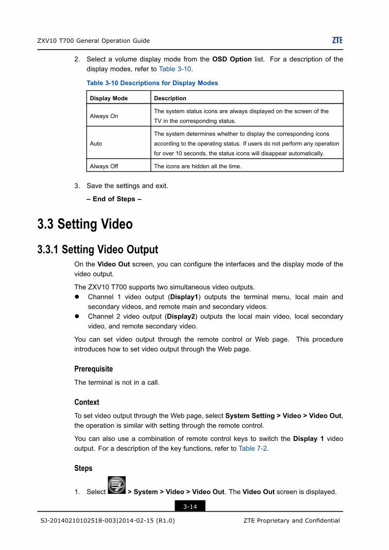
ZXV10 T700 General Operation Guide
2. Select a volume display mode from the OSD Option list. For a description of thedisplay modes, refer to Table 3-10.
Table 3-10 Descriptions for Display Modes
Display Mode Description
Always OnThe system status icons are always displayed on the screen of the
TV in the corresponding status.
Auto
The system determines whether to display the corresponding icons
according to the operating status. If users do not perform any operation
for over 10 seconds, the status icons will disappear automatically.
Always Off The icons are hidden all the time.
3. Save the settings and exit.
– End of Steps –
3.3 Setting Video
3.3.1 Setting Video OutputOn the Video Out screen, you can configure the interfaces and the display mode of thevideo output.
The ZXV10 T700 supports two simultaneous video outputs.l Channel 1 video output (Display1) outputs the terminal menu, local main and
secondary videos, and remote main and secondary videos.l Channel 2 video output (Display2) outputs the local main video, local secondary
video, and remote secondary video.
You can set video output through the remote control or Web page. This procedureintroduces how to set video output through the Web page.
PrerequisiteThe terminal is not in a call.
ContextTo set video output through the Web page, select System Setting > Video > Video Out,the operation is similar with setting through the remote control.
You can also use a combination of remote control keys to switch the Display 1 videooutput. For a description of the key functions, refer to Table 7-2.
Steps
1. Select > System > Video > Video Out. The Video Out screen is displayed.
3-14
SJ-20140210102518-003|2014-02-15 (R1.0) ZTE Proprietary and Confidential
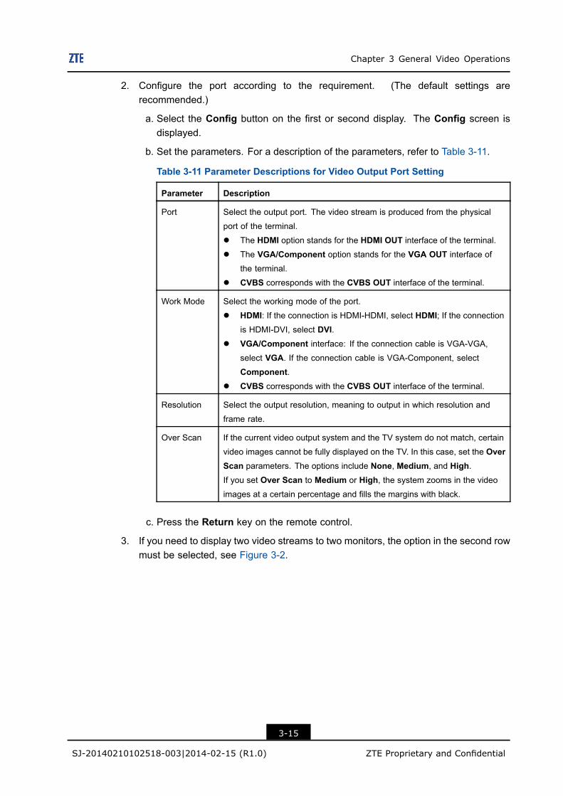
Chapter 3 General Video Operations
2. Configure the port according to the requirement. (The default settings arerecommended.)
a. Select the Config button on the first or second display. The Config screen isdisplayed.
b. Set the parameters. For a description of the parameters, refer to Table 3-11.
Table 3-11 Parameter Descriptions for Video Output Port Setting
Parameter Description
Port Select the output port. The video stream is produced from the physical
port of the terminal.
l The HDMI option stands for the HDMI OUT interface of the terminal.
l The VGA/Component option stands for the VGA OUT interface of
the terminal.
l CVBS corresponds with the CVBS OUT interface of the terminal.
Work Mode Select the working mode of the port.
l HDMI: If the connection is HDMI-HDMI, select HDMI; If the connectionis HDMI-DVI, select DVI.
l VGA/Component interface: If the connection cable is VGA-VGA,select VGA. If the connection cable is VGA-Component, select
Component.l CVBS corresponds with the CVBS OUT interface of the terminal.
Resolution Select the output resolution, meaning to output in which resolution and
frame rate.
Over Scan If the current video output system and the TV system do not match, certain
video images cannot be fully displayed on the TV. In this case, set the OverScan parameters. The options include None, Medium, and High.If you set Over Scan to Medium or High, the system zooms in the video
images at a certain percentage and fills the margins with black.
c. Press the Return key on the remote control.
3. If you need to display two video streams to two monitors, the option in the second rowmust be selected, see Figure 3-2.
3-15
SJ-20140210102518-003|2014-02-15 (R1.0) ZTE Proprietary and Confidential
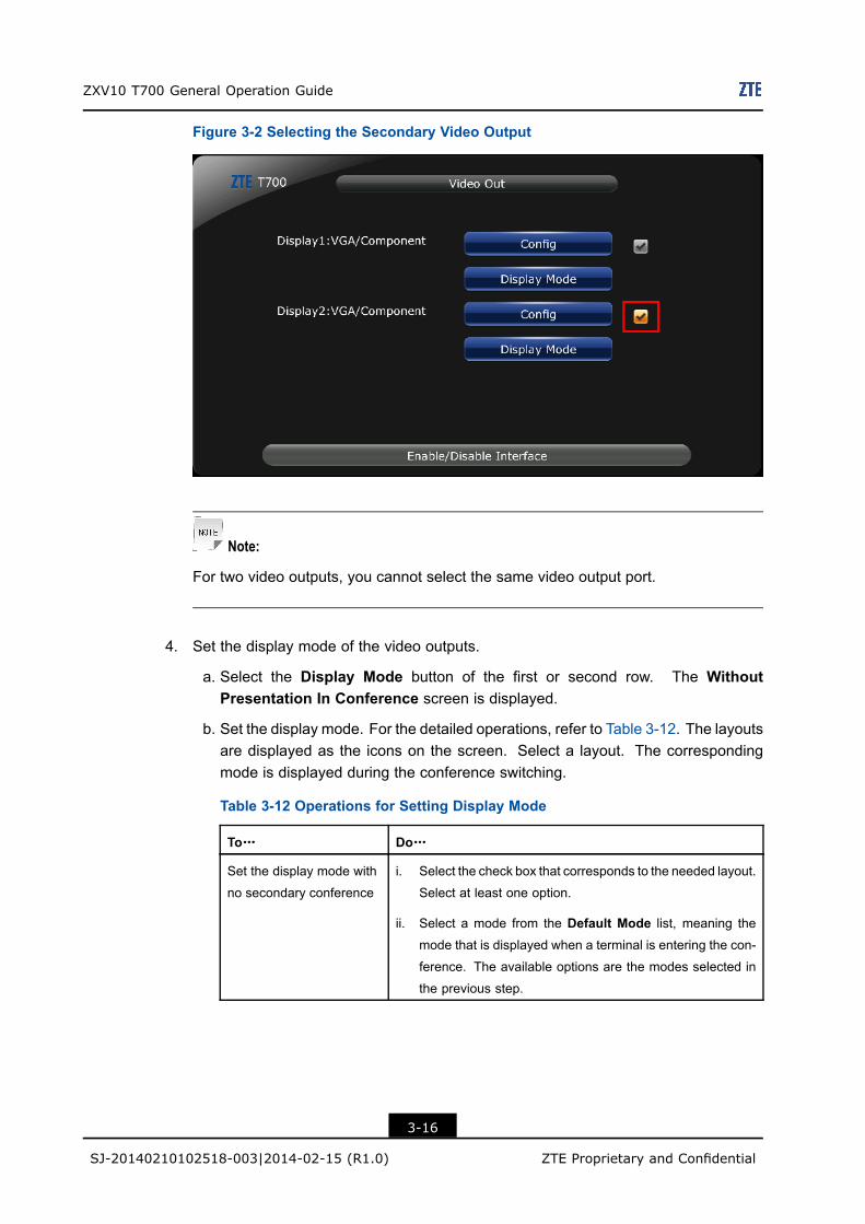
ZXV10 T700 General Operation Guide
Figure 3-2 Selecting the Secondary Video Output
Note:
For two video outputs, you cannot select the same video output port.
4. Set the display mode of the video outputs.
a. Select the Display Mode button of the first or second row. The WithoutPresentation In Conference screen is displayed.
b. Set the display mode. For the detailed operations, refer to Table 3-12. The layoutsare displayed as the icons on the screen. Select a layout. The correspondingmode is displayed during the conference switching.
Table 3-12 Operations for Setting Display Mode
To……… Do………
Set the display mode with
no secondary conference
i. Select the check box that corresponds to the needed layout.
Select at least one option.
ii. Select a mode from the Default Mode list, meaning the
mode that is displayed when a terminal is entering the con-
ference. The available options are the modes selected in
the previous step.
3-16
SJ-20140210102518-003|2014-02-15 (R1.0) ZTE Proprietary and Confidential
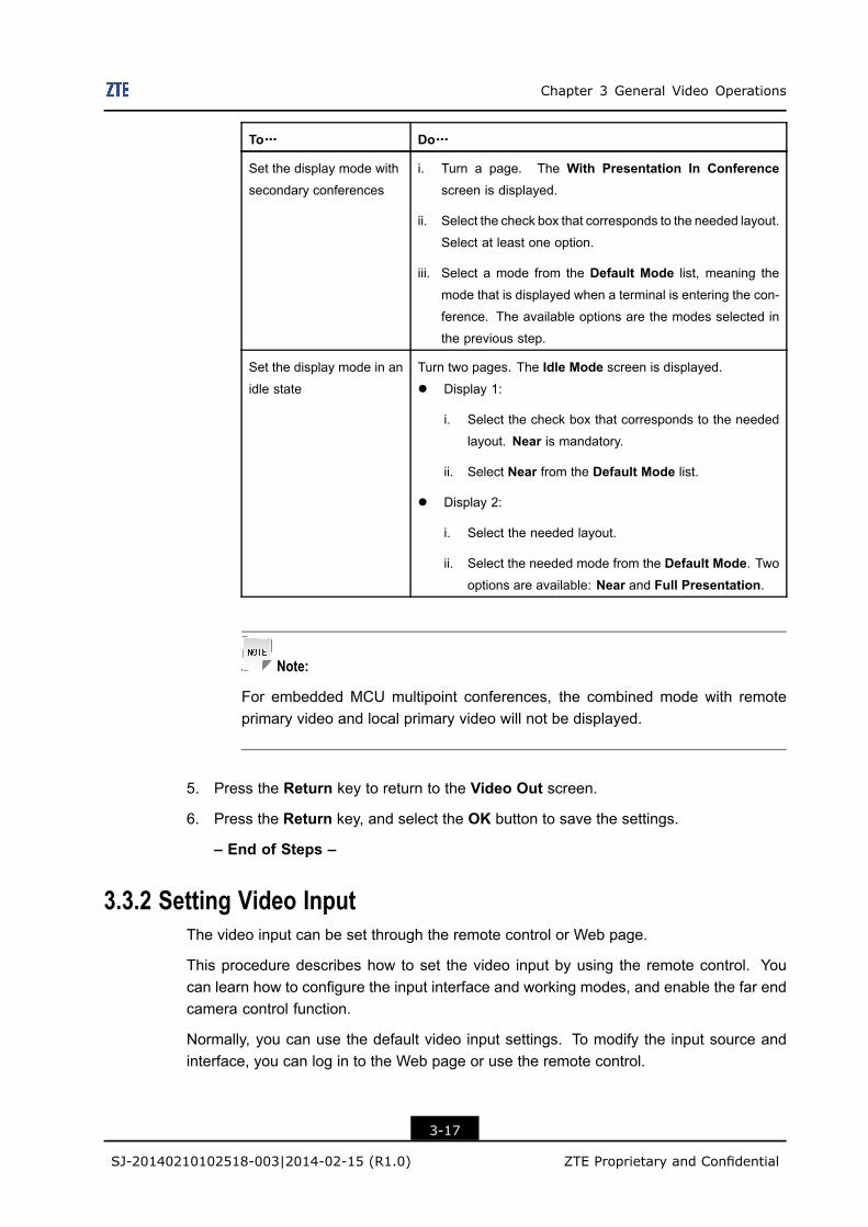
Chapter 3 General Video Operations
To……… Do………
Set the display mode with
secondary conferences
i. Turn a page. The With Presentation In Conferencescreen is displayed.
ii. Select the check box that corresponds to the needed layout.
Select at least one option.
iii. Select a mode from the Default Mode list, meaning the
mode that is displayed when a terminal is entering the con-
ference. The available options are the modes selected in
the previous step.
Set the display mode in an
idle state
Turn two pages. The Idle Mode screen is displayed.l Display 1:
i. Select the check box that corresponds to the needed
layout. Near is mandatory.
ii. Select Near from the Default Mode list.
l Display 2:
i. Select the needed layout.
ii. Select the needed mode from the Default Mode. Twooptions are available: Near and Full Presentation.
Note:
For embedded MCU multipoint conferences, the combined mode with remoteprimary video and local primary video will not be displayed.
5. Press the Return key to return to the Video Out screen.
6. Press the Return key, and select the OK button to save the settings.
– End of Steps –
3.3.2 Setting Video InputThe video input can be set through the remote control or Web page.
This procedure describes how to set the video input by using the remote control. Youcan learn how to configure the input interface and working modes, and enable the far endcamera control function.
Normally, you can use the default video input settings. To modify the input source andinterface, you can log in to the Web page or use the remote control.
3-17
SJ-20140210102518-003|2014-02-15 (R1.0) ZTE Proprietary and Confidential
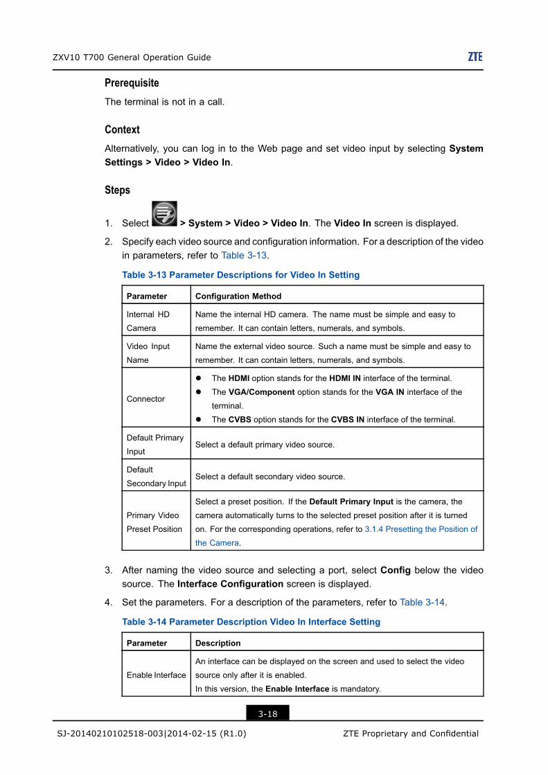
ZXV10 T700 General Operation Guide
PrerequisiteThe terminal is not in a call.
ContextAlternatively, you can log in to the Web page and set video input by selecting SystemSettings > Video > Video In.
Steps
1. Select > System > Video > Video In. The Video In screen is displayed.
2. Specify each video source and configuration information. For a description of the videoin parameters, refer to Table 3-13.
Table 3-13 Parameter Descriptions for Video In Setting
Parameter Configuration Method
Internal HD
Camera
Name the internal HD camera. The name must be simple and easy to
remember. It can contain letters, numerals, and symbols.
Video Input
Name
Name the external video source. Such a name must be simple and easy to
remember. It can contain letters, numerals, and symbols.
Connector
l The HDMI option stands for the HDMI IN interface of the terminal.
l The VGA/Component option stands for the VGA IN interface of the
terminal.
l The CVBS option stands for the CVBS IN interface of the terminal.
Default Primary
InputSelect a default primary video source.
Default
Secondary InputSelect a default secondary video source.
Primary Video
Preset Position
Select a preset position. If the Default Primary Input is the camera, thecamera automatically turns to the selected preset position after it is turned
on. For the corresponding operations, refer to 3.1.4 Presetting the Position of
the Camera.
3. After naming the video source and selecting a port, select Config below the videosource. The Interface Configuration screen is displayed.
4. Set the parameters. For a description of the parameters, refer to Table 3-14.
Table 3-14 Parameter Description Video In Interface Setting
Parameter Description
Enable Interface
An interface can be displayed on the screen and used to select the video
source only after it is enabled.
In this version, the Enable Interface is mandatory.
3-18
SJ-20140210102518-003|2014-02-15 (R1.0) ZTE Proprietary and Confidential
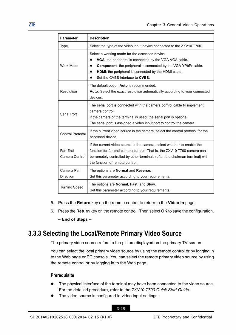
Chapter 3 General Video Operations
Parameter Description
Type Select the type of the video input device connected to the ZXV10 T700.
Work Mode
Select a working mode for the accessed device.
l VGA: the peripheral is connected by the VGA-VGA cable.
l Component: the peripheral is connected by the VGA-YPbPr cable.l HDMI: the peripheral is connected by the HDMI cable.l Set the CVBS interface to CVBS.
Resolution
The default option Auto is recommended.
Auto: Select the exact resolution automatically according to your connecteddevices.
Serial Port
The serial port is connected with the camera control cable to implement
camera control.
If the camera of the terminal is used, the serial port is optional.
The serial port is assigned a video input port to control the camera.
Control ProtocolIf the current video source is the camera, select the control protocol for the
accessed device.
Far End
Camera Control
If the current video source is the camera, select whether to enable the
function for far end camera control. That is, the ZXV10 T700 camera can
be remotely controlled by other terminals (often the chairman terminal) with
the function of remote control.
Camera Pan
Direction
The options are Normal and Reverse.Set this parameter according to your requirements.
Turning SpeedThe options are Normal, Fast, and Slow.Set this parameter according to your requirements.
5. Press the Return key on the remote control to return to the Video In page.
6. Press theReturn key on the remote control. Then selectOK to save the configuration.
– End of Steps –
3.3.3 Selecting the Local/Remote Primary Video SourceThe primary video source refers to the picture displayed on the primary TV screen.
You can select the local primary video source by using the remote control or by logging into the Web page or PC console. You can select the remote primary video source by usingthe remote control or by logging in to the Web page.
Prerequisitel The physical interface of the terminal may have been connected to the video source.
For the detailed procedure, refer to the ZXV10 T700 Quick Start Guide.l The video source is configured in video input settings.
3-19
SJ-20140210102518-003|2014-02-15 (R1.0) ZTE Proprietary and Confidential
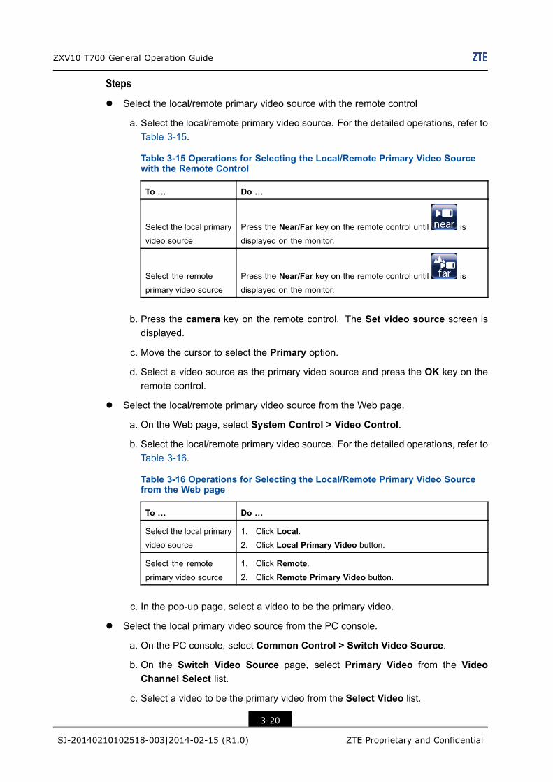
ZXV10 T700 General Operation Guide
Stepsl Select the local/remote primary video source with the remote control
a. Select the local/remote primary video source. For the detailed operations, refer toTable 3-15.
Table 3-15 Operations for Selecting the Local/Remote Primary Video Sourcewith the Remote Control
To … Do …
Select the local primary
video source
Press the Near/Far key on the remote control until is
displayed on the monitor.
Select the remote
primary video source
Press the Near/Far key on the remote control until is
displayed on the monitor.
b. Press the camera key on the remote control. The Set video source screen isdisplayed.
c. Move the cursor to select the Primary option.
d. Select a video source as the primary video source and press the OK key on theremote control.
l Select the local/remote primary video source from the Web page.
a. On the Web page, select System Control > Video Control.
b. Select the local/remote primary video source. For the detailed operations, refer toTable 3-16.
Table 3-16 Operations for Selecting the Local/Remote Primary Video Sourcefrom the Web page
To … Do …
Select the local primary
video source
1. Click Local.2. Click Local Primary Video button.
Select the remote
primary video source
1. Click Remote.2. Click Remote Primary Video button.
c. In the pop-up page, select a video to be the primary video.
l Select the local primary video source from the PC console.
a. On the PC console, select Common Control > Switch Video Source.
b. On the Switch Video Source page, select Primary Video from the VideoChannel Select list.
c. Select a video to be the primary video from the Select Video list.
3-20
SJ-20140210102518-003|2014-02-15 (R1.0) ZTE Proprietary and Confidential
Chapter 3 General Video Operations
d. Click Switch.
– End of Steps –
3.3.4 Selecting a Presentation SourceA presentation source refers to a video source except the primary video source. It can bethe video from a camera, computer, or DVD player.
The presentation source can be displayed on the secondary TV screen and can also bedisplayed on the primary TV screen by means of sending presentation.
You can select the presentation video source by using the remote control or by logging into the Web page or PC console.
Prerequisitel The physical interface of the terminal may have been connected to the video source.
For the detailed procedure, refer to the ZXV10 T700 Quick Start Guide.l The video source is configured in video input settings.
Stepsl Select the presentation source with the remote control
a. In the active video, press the camera key on the remote control. The Set videosource screen is displayed.
b. Move the cursor to select the Secondary option.
c. Select a video source to be the presentation source, and press the OK key on theremote control.
l Select the presentation source from the Web page
a. On the Web page, select System Control > Video Control.
b. Click the Presentation button.
c. In the pop-up dialog box, select a video source to be the presentation source.
l Select the presentation source from the PC console
a. Select Common Control > Switch Video Source.
b. On Switch Video Source page, select Presentation from the Video ChannelSelect list.
c. From the Select Video list, select a video source to be the presentation source.
d. Click Switch.
– End of Steps –
3-21
SJ-20140210102518-003|2014-02-15 (R1.0) ZTE Proprietary and Confidential

ZXV10 T700 General Operation Guide
This page intentionally left blank.
3-22
SJ-20140210102518-003|2014-02-15 (R1.0) ZTE Proprietary and Confidential
Chapter 4General Operations ofConference ControlTable of Contents
Viewing In-Conference Terminals ...............................................................................4-1Applying and Releasing Chairman..............................................................................4-1Selecting the Broadcast Source .................................................................................4-2Viewing Other Conference Sites.................................................................................4-4Controlling Conference Sound....................................................................................4-5Conference Management ...........................................................................................4-6
4.1 Viewing In-Conference TerminalsAfter a conference is started, a non-chairman terminal can view the in-conference terminallist.
Prerequisitel The conference is started.l The terminal that performs this operation is not the chairman terminal.
Steps1. Press the Conf key on the remote control. The Conference Control screen is
displayed.
2. Select Terminal List. The system displays all the in-conference terminals in a list.
– End of Steps –
4.2 Applying and Releasing ChairmanThe chairman in a multipoint conference can perform operations to control the conference.
l If a conference is started without a chairman, all the conference sites can apply forchairman.
l A conference can only have one chairman. The terminal that is chairman can controlthe conference.
l Only after the chairman site releases the chairman token, can other conference sitesapply for chairman.
4-1
SJ-20140210102518-003|2014-02-15 (R1.0) ZTE Proprietary and Confidential
ZXV10 T700 General Operation Guide
Prerequisitel Terminals can only apply for chairman if the conference is controlled by the MCU or if
it is a multipoint conference through the embedded MCU.l Only non-chairman conference sites can apply for chairman and only when there is
no chairmanl Only chairman conference sites can release the chairman token.
Stepsl The administrator can apply for or release chairman on the remote control. For the
detailed operations, refer to Table 4-1.
Table 4-1 Operations for Applying and Releasing Chairman on the Remote Control
To……… Do………
Apply for
Chairman
1. During a conference, press the Conf key on the remote control. TheConference Control screen is displayed.
2. Select the 1. Apply Chairman option. If the conference has no
chairman, the application for chairman is successful.
Release
Chairman
1. During a conference, press the Conf key on the remote control. TheConference Control screen is displayed.
2. Select the 9. Release Chairman option and press OK.
Note:
If the conference already has a chairman, the application for chairman fails. In thiscase, the system displays a dialog box showing the name of the current chairmanterminal.
l Release or apply for chairman from the PC console. For the detailed operations, referto Table 4-2.
Table 4-2 Operations for Applying and Releasing Chairman from the PC Console
To……… Do………
Apply for chairman Select Conference Control > Apply Chairman.
Release Chairman Select Conference Control > Apply Chairman.
– End of Steps –
4.3 Selecting the Broadcast Sourcel The chairman terminal can select itself or any conference site to be the broadcast
source.
4-2
SJ-20140210102518-003|2014-02-15 (R1.0) ZTE Proprietary and Confidential
Chapter 4 General Operations of Conference Control
l The video of the site to be the broadcast source will be displayed at all the otherconference sites.
This procedure describes the Self Broadcast, Broadcast Site, and Specify Speechoperations performed by the chairman terminal.
PrerequisiteThe local terminal is the chairman terminal in a multipoint conference.
Only when multipoint conferences are started on the MCU server, can the chairmanterminal perform the Specify Speech operation.
ContextFor the comparison of the Self Broadcast, Broadcast Site, and Specify Speechoperations, refer to Table 4-3:
Table 4-3 Descriptions for Broadcast Source Comparison
Item Result
Self Broadcast l The chairman terminal acts as the broadcast source.
l The microphone and sound status of the other conference sites keep
their original status.
Site Broadcast l The broadcast terminal is the broadcast source.
l The microphone and sound status of the other conference sites keep
their original status.
Specified Speech l The terminal that is specified for speech is the broadcast source.
l The microphones and sound of the chairman terminal and the terminal
that is broadcast are enabled.
l The microphones of the other conference sites are disabled.
l The sound of the other conference sites is enabled.
Steps1. Press the Conf key on the remote control at the chairman terminal. The Conference
Control menu is displayed.
2. Select the broadcast source. For the detailed operations, refer to Table 4-4:
Table 4-4 Operations for Selecting the Broadcast Source
To……… Do………
Broadcast Itself Select 1. Self Broadcast.
Broadcast Site i. Select 2. Broadcast Site. A dialog box is displayed.
ii. Select a conference site, and press theOK key on the remote control.
4-3
SJ-20140210102518-003|2014-02-15 (R1.0) ZTE Proprietary and Confidential
ZXV10 T700 General Operation Guide
To……… Do………
Specify Speech i. Select 3. Specify Speech. A dialog box is displayed.
ii. Select the desired conference site and press the OK key on the re-
mote control.
l The broadcast source icon is displayed on the right of the broadcastterminal’s monitor to show that the broadcast mode is activated.
l In the terminal list, the terminal that acts as the broadcast source is identified as
.
– End of Steps –
4.4 Viewing Other Conference SitesPerform either of the following operations to view other conference sites:l Chairman View: The chairman terminal selects a conference site and views its video.
If necessary, the chairman terminal selects any other conference site and views thecorresponding video.
l Chairman Browse: The chairman selects several conference sites and views theirvideo in turn after setting the desired interval.
Prerequisitel The conference is a multipoint conference started on theMCU, for example, the M900.l The local terminal is the chairman terminal and acts as the broadcast source.
Steps1. Press the Conf key on the remote control. The Conference Control menu is
displayed.
2. View other conference sites. For the detailed operations, refer to Table 4-5:
Table 4-5 Operations for Viewing Other Conference Sites
To……… Do………
View other conference
sites
i. Select 5. Chairman View. The Chairman View screen is dis-
played.
ii. Select the desired conference site, and press the OK key on the
remote control.
iii. Determine whether to view another conference site.
l If yes, go to step ii.
l If no, go to step iv.
iv. Press the Return key on the remote control.
4-4
SJ-20140210102518-003|2014-02-15 (R1.0) ZTE Proprietary and Confidential
Chapter 4 General Operations of Conference Control
To……… Do………
Browse other
conference sites
i. Select 6. Chairman Browse. The Chairman Browse screen is
displayed.
ii. Select one or more terminals. You can also select all terminals.
iii. In the Interval(s) text box, enter the interval for displaying confer-ence sites in turn. "Enter the time value in minutes.
iv. SelectBrowse. The chairman terminal begins to browse the videostreams from the selected conference sites.
These selected sites will be displayed by turns on the Chairman’s
screen.
v. (Optional) Select Pause to suspend the browsing of the confer-
ence sites. Select Continue to continue to browse the conferencesites.
vi. Select Stop Browsing to stop browsing the video streams from
the conference sites.
– End of Steps –
4.5 Controlling Conference SoundThe chairman terminal can enable or disable the microphones and sound of otherconference sites.
Prerequisitel The conference is a multipoint conference started on theMCU, for example, the M900.l The local terminal is the chairman terminal in the conference.
Steps1. Press the Conf key on the remote control. The Conference Control menu is
displayed.
2. Select 7. Mute/Silent.
3. Control conference sound. For the detailed operations, refer to Table 4-6.
Table 4-6 Operations for Controlling Conference Sound
To……… Do………
Enable/Disable
Speech
l Select 1. Speech Control. The Speech Control screen is
displayed.
l Select the desired conference site name to enable or disable this
site to be heard in the conference.
Select Forbid all to Speak or Allow all to Speak to disable orenable all sites to be heard in the conference.
4-5
SJ-20140210102518-003|2014-02-15 (R1.0) ZTE Proprietary and Confidential
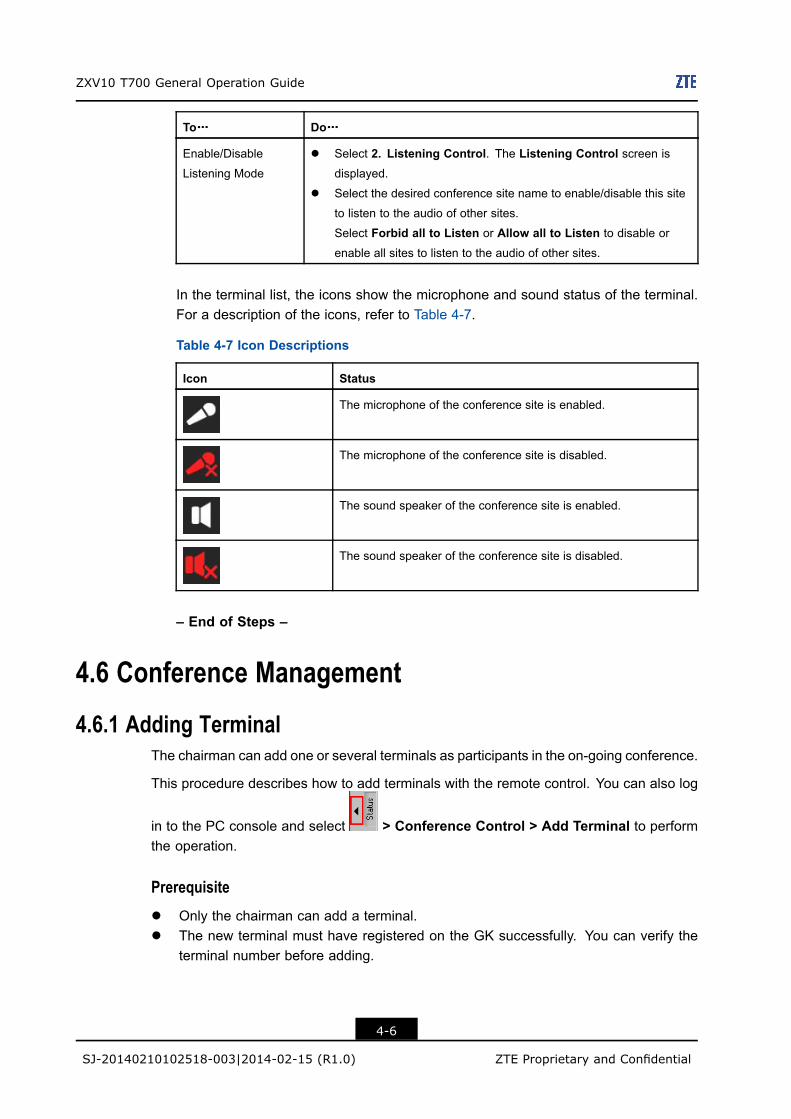
ZXV10 T700 General Operation Guide
To……… Do………
Enable/Disable
Listening Mode
l Select 2. Listening Control. The Listening Control screen isdisplayed.
l Select the desired conference site name to enable/disable this site
to listen to the audio of other sites.
Select Forbid all to Listen or Allow all to Listen to disable or
enable all sites to listen to the audio of other sites.
In the terminal list, the icons show the microphone and sound status of the terminal.For a description of the icons, refer to Table 4-7.
Table 4-7 Icon Descriptions
Icon Status
The microphone of the conference site is enabled.
The microphone of the conference site is disabled.
The sound speaker of the conference site is enabled.
The sound speaker of the conference site is disabled.
– End of Steps –
4.6 Conference Management
4.6.1 Adding TerminalThe chairman can add one or several terminals as participants in the on-going conference.
This procedure describes how to add terminals with the remote control. You can also log
in to the PC console and select > Conference Control > Add Terminal to performthe operation.
Prerequisitel Only the chairman can add a terminal.l The new terminal must have registered on the GK successfully. You can verify the
terminal number before adding.
4-6
SJ-20140210102518-003|2014-02-15 (R1.0) ZTE Proprietary and Confidential
Chapter 4 General Operations of Conference Control
Steps1. Press the Conf key on the remote control.
2. Select 8. Conf Management. The Conference Control menu is displayed.
3. Select 1. Add Terminal. A dialog box is displayed.
4. Enter the terminal number registered in the GK server.
5. Select Add.
The terminal becomes a new participant in the on-going conference.
– End of Steps –
4.6.2 Disconnecting a terminalThe chairman can disconnect one or several participant terminals in the on-goingconference.
The disconnected terminal is displayed in the waiting list to reconnect.
The chairman can add the disconnected terminal into the conference again by selectingCall Terminal.
PrerequisiteOnly the chairman can disconnect a terminal.
Stepsl Disconnecting a terminal with the remote control
a. Press the Conf key on the remote control. The Conference Control menu isdisplayed.
b. Select Conference Management > Disconnect Terminal . The DisconnectTerminal page is displayed.
c. Select the conference site name, and press OK.
l Disconnecting a terminal with the PC console
a. Log in to the PC console, select > Conference Control, and right-click thetarget terminal to open the menu.
b. Select Disconnect Terminal and confirm the selection.
– End of Steps –
4.6.3 Prolonging a ConferenceThe duration of the conference is set before a multipoint conference starts. The chairmancan extend the duration during a conference if it is not enough. When performing thisoperation, verify that total conference period does not exceed 72 hours.
4-7
SJ-20140210102518-003|2014-02-15 (R1.0) ZTE Proprietary and Confidential
ZXV10 T700 General Operation Guide
This procedure describes how to extend a conferencewith the remote control. You can also
log in to the PC console, and select > Conference Control > Prolong Conferenceto extend the conference.
Prerequisitel This operation cannot be performed in a conference whose duration is unlimited.l Only the chairman can extend a conference.
Steps1. During a conference, pressConf on the remote control, and selectConf Management
in the pop-up menu. The Conf Management menu is displayed.
2. Select 5. Extend Conference. A dialog box is displayed.
3. Enter the desired minutes.
4. Select Set.
– End of Steps –
ExampleIf you want to extend the conference for 30 minutes, perform the following steps:
1. Press Conf on the remote control to open the menu, and then select ConfManagement.
2. On the Conf Management page, select 5. Extend Conference. A dialog box isdisplayed.
3. Enter 30 minutes.4. Select Set.
4.6.4 Ending a ConferenceThe duration of the conference is set before a multipoint conference starts. The chairmancan close the conference ahead of the scheduled end time.
This procedure describes how to end a conference with the remote control. You can also
log in to the PC console, and select > Conference Control > End Conference toend the conference.
PrerequisiteOnly the chairman can end a conference.
Steps1. During a conference, press Conf. The Conference Control menu is displayed.
4-8
SJ-20140210102518-003|2014-02-15 (R1.0) ZTE Proprietary and Confidential
Chapter 4 General Operations of Conference Control
2. SelectConf Management > End Conference, and pressOK to confirm the operation.
– End of Steps –
4-9
SJ-20140210102518-003|2014-02-15 (R1.0) ZTE Proprietary and Confidential

ZXV10 T700 General Operation Guide
This page intentionally left blank.
4-10
SJ-20140210102518-003|2014-02-15 (R1.0) ZTE Proprietary and Confidential
Chapter 5Dual Video OperationTable of Contents
Overview of Dual Video Streaming .............................................................................5-1Managing a Presentation............................................................................................5-2Displaying Presentations ...........................................................................................5-4
5.1 Overview of Dual Video StreamingDual video streaming means transmitting primary and secondary video simultaneously.Dual video streaming shares the bandwidth resource. Dual video streaming could be thecombination of any two items, including the camera image, the image of the computerdesktop, and the video from a DVD or recorder.
In general, the first video streaming, or primary video, which occupies most of thebandwidth is used to transmit camera image at the main site. The secondary videostreaming is used to transmit the image of the desktop, such as slides for training andlearning or files of other formats. Normally, this video streaming is called presentationsor secondary video. Each of the presentation and the primary video occupy half of thebandwidth by default.
The H.239 protocol is an international standard formulated by ITU-T. The H.239 protocolcan realize the interoperability between products made by different manufacturers in termsof presentation.
For a description of the presentation functions, refer to Table 5-1.
Table 5-1 Descriptions for Presentation Functions
Function Description
Presentation
Contended
If Presentation Contended is enabled on the terminal which is sending
a presentation, other terminals can send presentation by applying for the
presentations token manually.
If Presentation Contended is disabled on the terminal which is sending a
presentation, other terminals can not send a presentation.
Auto Send
Presentation
If the local terminal enables Auto Send Presentation, the terminal will
automatically check the configuration and connection status of the presentation.
Once the status is confirmed and there are no other presentations in the
conference, the terminal sends the presentation automatically.
5-1
SJ-20140210102518-003|2014-02-15 (R1.0) ZTE Proprietary and Confidential
ZXV10 T700 General Operation Guide
5.2 Managing a PresentationIf there is only one video streaming input, the local terminal can send the presentation(secondary video) to the conference.
The local terminal can send presentations by applying for the presentation token from theprevious token owner if the previous token owner has enabled Presentation Contended.
Before sending the presentation, you can preview the local presentation and verify that itis correct.
Prerequisitel Preparations
à The presentation source is configured. For the configuration operations, refer to3.3.4 Selecting a Presentation Source.
à The terminal is connected to the device that provides the secondary video source(for example, if any desktop content needs to be sent during the conference,the PC has been connected to the terminal’s VGA IN port). For the detailedoperations, refer to the ZXV10 T700 Quick Start Guide.
à Enable Presentation is selected on the terminal. That is, Enable Presentationunder General > Call Option is selected.
l Operation Prerequisites
To… Do…
Preview the
presentation
The local presentation can be previewed when the terminal is idle
or in a conference.
Send the presentation à The terminal can send a presentation only when it is in a confer-
ence.
à No terminal is sending the presentation in the current conference,
or the terminal that is sending the presentation has enabled the
Presentation Contended function.
Close the presentation Only the terminal that sends a presentation and the chairman in the
multipoint conference can close the presentation.
StepsOperation by Using the Remote Control
l Manage a presentation with the remote control. For the detailed operations, refer toTable 5-2.
5-2
SJ-20140210102518-003|2014-02-15 (R1.0) ZTE Proprietary and Confidential
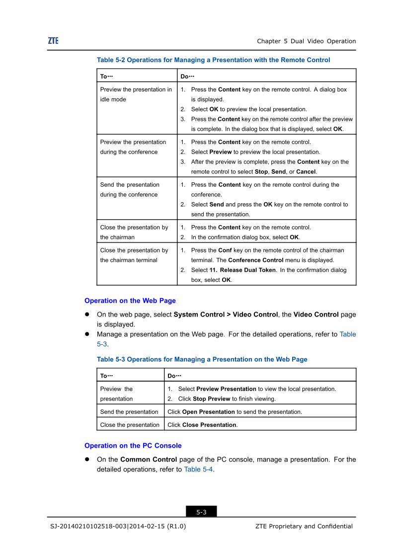
Chapter 5 Dual Video Operation
Table 5-2 Operations for Managing a Presentation with the Remote Control
To……… Do………
Preview the presentation in
idle mode
1. Press the Content key on the remote control. A dialog box
is displayed.
2. Select OK to preview the local presentation.
3. Press the Content key on the remote control after the previewis complete. In the dialog box that is displayed, select OK.
Preview the presentation
during the conference
1. Press the Content key on the remote control.2. Select Preview to preview the local presentation.
3. After the preview is complete, press the Content key on theremote control to select Stop, Send, or Cancel.
Send the presentation
during the conference
1. Press the Content key on the remote control during the
conference.
2. Select Send and press the OK key on the remote control to
send the presentation.
Close the presentation by
the chairman
1. Press the Content key on the remote control.2. In the confirmation dialog box, select OK.
Close the presentation by
the chairman terminal
1. Press the Conf key on the remote control of the chairmanterminal. The Conference Control menu is displayed.
2. Select 11. Release Dual Token. In the confirmation dialogbox, select OK.
Operation on the Web Page
l On the web page, select System Control > Video Control, the Video Control pageis displayed.
l Manage a presentation on the Web page. For the detailed operations, refer to Table5-3.
Table 5-3 Operations for Managing a Presentation on the Web Page
To……… Do………
Preview the
presentation
1. Select Preview Presentation to view the local presentation.
2. Click Stop Preview to finish viewing.
Send the presentation Click Open Presentation to send the presentation.
Close the presentation Click Close Presentation.
Operation on the PC Console
l On the Common Control page of the PC console, manage a presentation. For thedetailed operations, refer to Table 5-4.
5-3
SJ-20140210102518-003|2014-02-15 (R1.0) ZTE Proprietary and Confidential
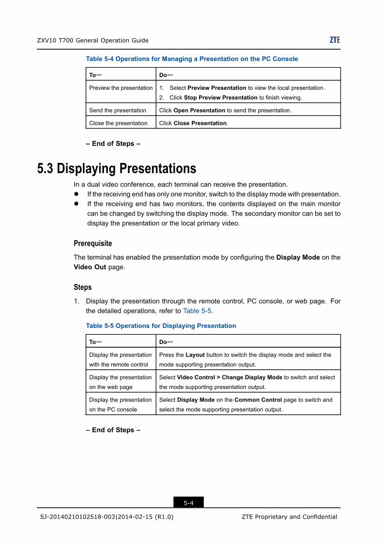
ZXV10 T700 General Operation Guide
Table 5-4 Operations for Managing a Presentation on the PC Console
To……… Do………
Preview the presentation 1. Select Preview Presentation to view the local presentation.
2. Click Stop Preview Presentation to finish viewing.
Send the presentation Click Open Presentation to send the presentation.
Close the presentation Click Close Presentation.
– End of Steps –
5.3 Displaying PresentationsIn a dual video conference, each terminal can receive the presentation.l If the receiving end has only onemonitor, switch to the display mode with presentation.l If the receiving end has two monitors, the contents displayed on the main monitor
can be changed by switching the display mode. The secondary monitor can be set todisplay the presentation or the local primary video.
PrerequisiteThe terminal has enabled the presentation mode by configuring the Display Mode on theVideo Out page.
Steps1. Display the presentation through the remote control, PC console, or web page. For
the detailed operations, refer to Table 5-5.
Table 5-5 Operations for Displaying Presentation
To……… Do………
Display the presentation
with the remote control
Press the Layout button to switch the display mode and select themode supporting presentation output.
Display the presentation
on the web page
Select Video Control > Change Display Mode to switch and selectthe mode supporting presentation output.
Display the presentation
on the PC console
Select Display Mode on the Common Control page to switch andselect the mode supporting presentation output.
– End of Steps –
5-4
SJ-20140210102518-003|2014-02-15 (R1.0) ZTE Proprietary and Confidential
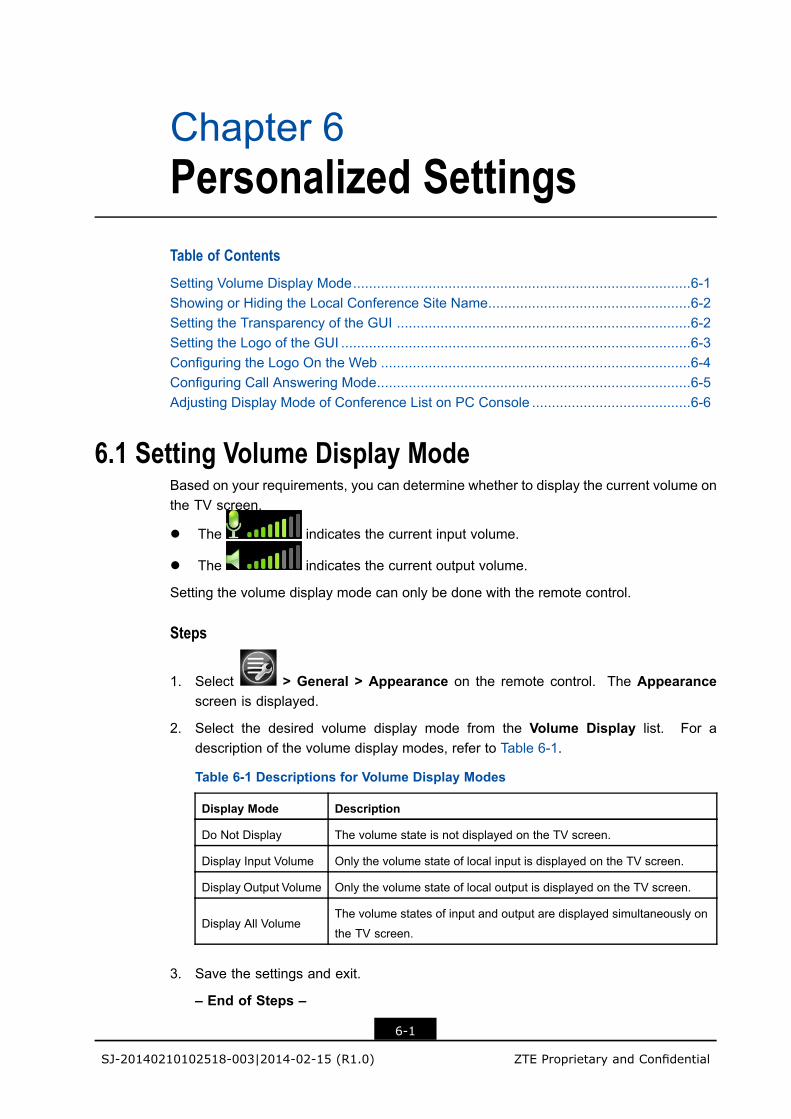
Chapter 6Personalized SettingsTable of Contents
Setting Volume Display Mode.....................................................................................6-1Showing or Hiding the Local Conference Site Name...................................................6-2Setting the Transparency of the GUI ..........................................................................6-2Setting the Logo of the GUI ........................................................................................6-3Configuring the Logo On the Web ..............................................................................6-4Configuring Call Answering Mode...............................................................................6-5Adjusting Display Mode of Conference List on PC Console ........................................6-6
6.1 Setting Volume Display ModeBased on your requirements, you can determine whether to display the current volume onthe TV screen.
l The indicates the current input volume.
l The indicates the current output volume.
Setting the volume display mode can only be done with the remote control.
Steps
1. Select > General > Appearance on the remote control. The Appearancescreen is displayed.
2. Select the desired volume display mode from the Volume Display list. For adescription of the volume display modes, refer to Table 6-1.
Table 6-1 Descriptions for Volume Display Modes
Display Mode Description
Do Not Display The volume state is not displayed on the TV screen.
Display Input Volume Only the volume state of local input is displayed on the TV screen.
Display Output Volume Only the volume state of local output is displayed on the TV screen.
Display All VolumeThe volume states of input and output are displayed simultaneously on
the TV screen.
3. Save the settings and exit.
– End of Steps –
6-1
SJ-20140210102518-003|2014-02-15 (R1.0) ZTE Proprietary and Confidential
ZXV10 T700 General Operation Guide
6.2 Showing or Hiding the Local Conference Site NameBased on your requirements, you can determine whether to display the name of the localconference site on the remote TV screen.
PrerequisiteThe terminal is not in a call.
Steps
1. Select > General > Appearance by using the remote control, or select SystemSettings >General > Appearance after logging in to theWeb page. TheAppearancepage is displayed.
2. Select Sending Terminal from the Name Option list.
The name of the local conference site is displayed on the TV screen.
Note:
Three options are available for name display.l Sending Terminal: The name of the local conference site and the local picture
are combined at the local end and then transmitted, that is, the remote end canview the terminal name when receiving the picture.
l Receiving Terminal: The name of the remote conference and the picture arecombined at the receiving end, that is, the receiving end can view the remotename all the time. This feature is not currently available.
l Disable: The name of the conference site and the picture are not combined. Inthis case, you can view only the picture.
– End of Steps –
6.3 Setting the Transparency of the GUIOn the Appearance screen, set the transparency of the GUI menu accordingly.
This procedure describes how to set the transparency of the GUI menu by using the remotecontrol.
PrerequisiteThe terminal is not in a call.
6-2
SJ-20140210102518-003|2014-02-15 (R1.0) ZTE Proprietary and Confidential
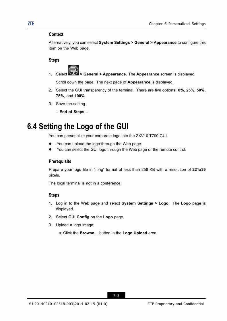
Chapter 6 Personalized Settings
ContextAlternatively, you can select System Settings > General > Appearance to configure thisitem on the Web page.
Steps
1. Select > General > Appearance. The Appearance screen is displayed.
Scroll down the page. The next page of Appearance is displayed.
2. Select the GUI transparency of the terminal. There are five options: 0%, 25%, 50%,75%, and 100%.
3. Save the setting.
– End of Steps –
6.4 Setting the Logo of the GUIYou can personalize your corporate logo into the ZXV10 T700 GUI.
l You can upload the logo through the Web page.l You can select the GUI logo through the Web page or the remote control.
PrerequisitePrepare your logo file in “.png” format of less than 256 KB with a resolution of 221x39pixels.
The local terminal is not in a conference.
Steps1. Log in to the Web page and select System Settings > Logo. The Logo page is
displayed.
2. Select GUI Config on the Logo page.
3. Upload a logo image:
a. Click the Browse... button in the Logo Upload area.
6-3
SJ-20140210102518-003|2014-02-15 (R1.0) ZTE Proprietary and Confidential
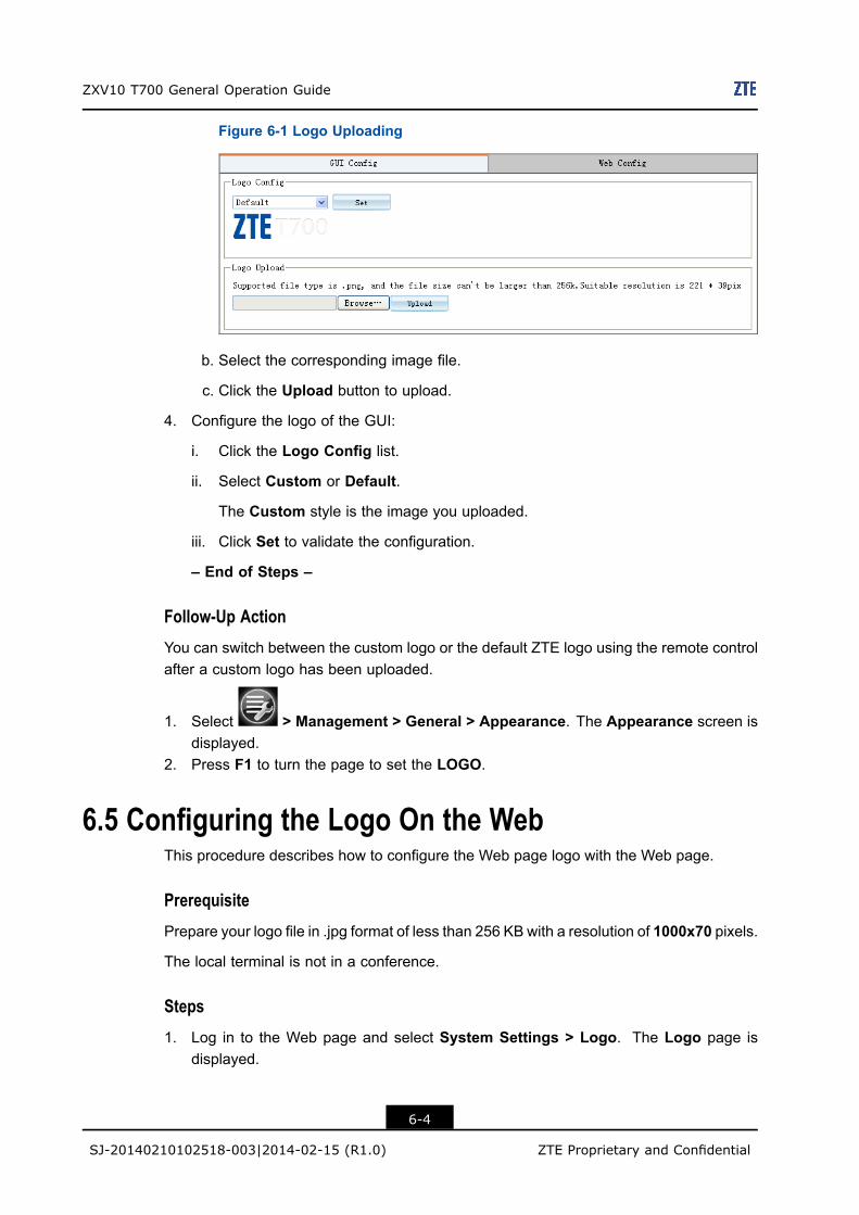
ZXV10 T700 General Operation Guide
Figure 6-1 Logo Uploading
b. Select the corresponding image file.
c. Click the Upload button to upload.
4. Configure the logo of the GUI:
i. Click the Logo Config list.
ii. Select Custom or Default.
The Custom style is the image you uploaded.
iii. Click Set to validate the configuration.
– End of Steps –
Follow-Up ActionYou can switch between the custom logo or the default ZTE logo using the remote controlafter a custom logo has been uploaded.
1. Select > Management > General > Appearance. The Appearance screen isdisplayed.
2. Press F1 to turn the page to set the LOGO.
6.5 Configuring the Logo On the WebThis procedure describes how to configure the Web page logo with the Web page.
PrerequisitePrepare your logo file in .jpg format of less than 256 KB with a resolution of 1000x70 pixels.
The local terminal is not in a conference.
Steps1. Log in to the Web page and select System Settings > Logo. The Logo page is
displayed.
6-4
SJ-20140210102518-003|2014-02-15 (R1.0) ZTE Proprietary and Confidential
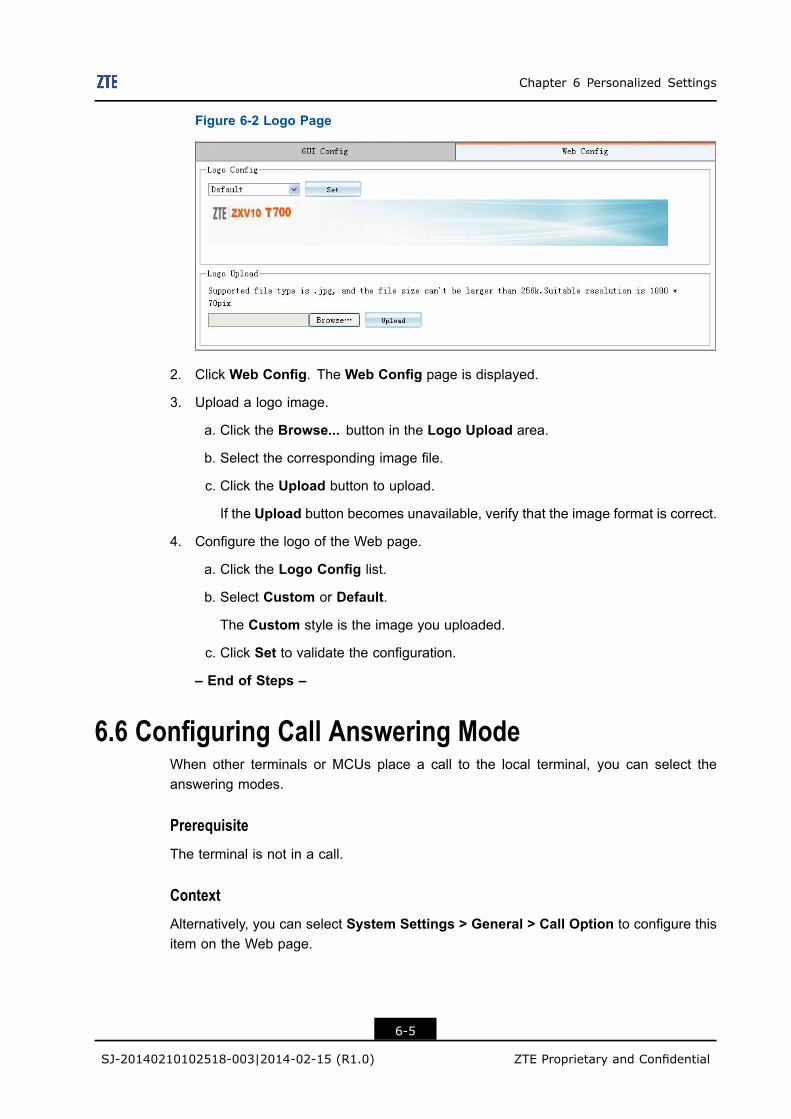
Chapter 6 Personalized Settings
Figure 6-2 Logo Page
2. Click Web Config. The Web Config page is displayed.
3. Upload a logo image.
a. Click the Browse... button in the Logo Upload area.
b. Select the corresponding image file.
c. Click the Upload button to upload.
If the Upload button becomes unavailable, verify that the image format is correct.
4. Configure the logo of the Web page.
a. Click the Logo Config list.
b. Select Custom or Default.
The Custom style is the image you uploaded.
c. Click Set to validate the configuration.
– End of Steps –
6.6 Configuring Call Answering ModeWhen other terminals or MCUs place a call to the local terminal, you can select theanswering modes.
PrerequisiteThe terminal is not in a call.
ContextAlternatively, you can select System Settings > General > Call Option to configure thisitem on the Web page.
6-5
SJ-20140210102518-003|2014-02-15 (R1.0) ZTE Proprietary and Confidential
ZXV10 T700 General Operation Guide
Steps
1. Select > General > Call Option by using the remote control.
2. For a point-to-point call, select a mode from the P2P Answer list. For a description ofthe call answering modes, refer to Table 6-2.
Table 6-2 Descriptions for Call Answering Modes
Answering Mode Description
AutoIf a call is received, the terminal automatically answers the call and
connects to the conference.
ManualIf a call is received, the terminal displays a call prompt asking you
whether to accept the call.
Do not Disturb
If a call is received, the terminal directly rejects the call.
In this case, the TV screen at the remote end prompts that the peer
end is busy.
Auto (Only audio)If there is an incoming call, the ZXV10 T700 terminal directly
connects the conference in an audio mode.
3. Select answering mode in the Multipoint Answer list. For a description of the callanswering modes, refer to Table 6-2
4. Set Auto Answer Mic Mutel Enable: The terminal automatically joins the conference when it is called. The
microphone of the local end is turned off.l Disable: The terminal automatically joins the conference when it is called. The
microphone of the local remains in the current state.
5. Save the configuration to make the configuration take effect.
– End of Steps –
6.7 Adjusting Display Mode of Conference List on PCConsole
The terminal list on the PC console has three display modes. You can change the displaymode.
Steps
1. Log in to the PC console and select > Conf Control. The Conference Controlpage is displayed.
2. Select any icon in to change the display mode.
6-6
SJ-20140210102518-003|2014-02-15 (R1.0) ZTE Proprietary and Confidential
Chapter 6 Personalized Settings
For detailed icon meanings, refer to the descriptions related to the PC console in theZXV10 T700 PC Console Operation Guide.
– End of Steps –
6-7
SJ-20140210102518-003|2014-02-15 (R1.0) ZTE Proprietary and Confidential
ZXV10 T700 General Operation Guide
This page intentionally left blank.
6-8
SJ-20140210102518-003|2014-02-15 (R1.0) ZTE Proprietary and Confidential
Chapter 7Other OperationsTable of Contents
Viewing Version Information .......................................................................................7-1Performing Network Test ............................................................................................7-1Key Combinations of the Remote Control ...................................................................7-2
7.1 Viewing Version InformationOn the version information screen, the user can view the software version but cannotmodify it.
You can view the version information with the remote control, on the Web page, or on thePC console.
Steps
l View with the remote control: Select > Diagnostics > Version Info.. TheVersion Info. screen is displayed.
l View on the Web page: You can view the version information by clicking SystemDiagnostics > Version Info. after logging in to the Web page.
l View through the PC console: You can view the version information by clickingSystemDiagnostics > Version Info. after logging in to the PC console.
– End of Steps –
7.2 Performing Network TestThe network test aims to test whether the IP network between the ZXV10 T700 terminaland other devices including MCUs, PCs, and video conference terminals is reliable.
This procedure describes how to perform a network test with the remote control.
PrerequisiteThe ZXV10 T700 terminal is already connected to the network and the network status isgood.
ContextAlternatively, you can log in to the Web page of the terminal and select SystemDiagnostics > Network Test. The Network Test page is displayed.
7-1
SJ-20140210102518-003|2014-02-15 (R1.0) ZTE Proprietary and Confidential
ZXV10 T700 General Operation Guide
Steps
1. Select > Diagnostics > Network Test by using the remote control.
2. Set the network test parameters. For a description of the parameter, refer to Table 7-1.
Table 7-1 Parameter Descriptions for Network Test Setting
Parameter Description
Remote Address IP address of the remote device.
Times Number of network tests. The number ranges from 1 to 65535, and the
value 4 is recommended.
Interval (ms) Interval of network tests. The interval ranges from 100 to 65535 ms, and
the value 100 ms is recommended.
Packet Size Size of packets in the network test. The packet size ranges from 1 to
65500 bytes, and the value 32 bytes is recommended.
3. Move the cursor to the Ping start button, and press the OK key on the remote controlto start the test.
The test result is as follows:l If Total Sent Packets=Total Received Packets, the remote device has been
successfully reached.l If Total Sent Packets>Total Received Packets>0, the remote device has been
reached but some packets are lost.l If Total Received Packets=0, the remote device has not been successfully
reached. Verify that the IP connection of the local terminal or the remote terminalis incorrect.
– End of Steps –
7.3 Key Combinations of the Remote ControlIf the ZXV10 T700 terminal is not in a conference, with the combinations of theDisconnect,*, #, and the number keys, you can quickly switch between the main video outputs (Display1), perform the local loopback test, and restore the factory default settings.
Switch Main Video OutputFor the detailed operations, refer to Table 7-2.
7-2
SJ-20140210102518-003|2014-02-15 (R1.0) ZTE Proprietary and Confidential
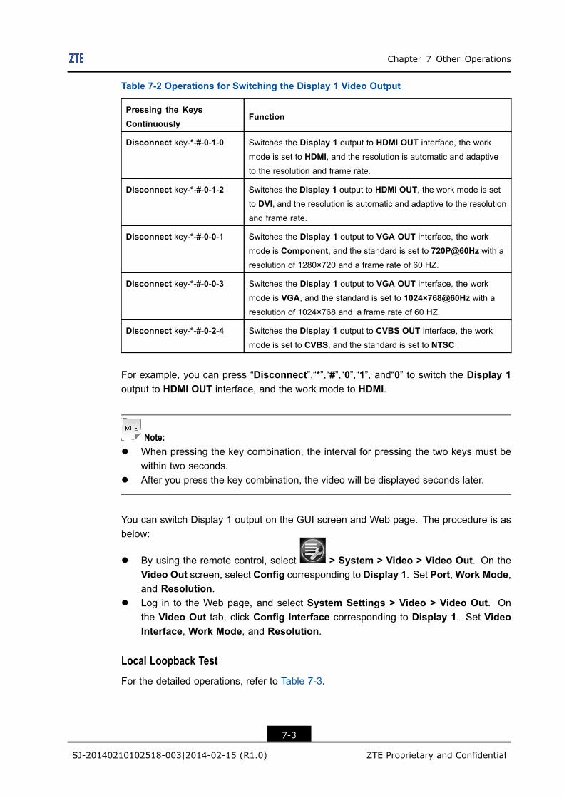
Chapter 7 Other Operations
Table 7-2 Operations for Switching the Display 1 Video Output
Pressing the KeysContinuously
Function
Disconnect key-*-#-0-1-0 Switches the Display 1 output to HDMI OUT interface, the work
mode is set to HDMI, and the resolution is automatic and adaptiveto the resolution and frame rate.
Disconnect key-*-#-0-1-2 Switches the Display 1 output to HDMI OUT, the work mode is setto DVI, and the resolution is automatic and adaptive to the resolutionand frame rate.
Disconnect key-*-#-0-0-1 Switches the Display 1 output to VGA OUT interface, the work
mode is Component, and the standard is set to 720P@60Hz with aresolution of 1280×720 and a frame rate of 60 HZ.
Disconnect key-*-#-0-0-3 Switches the Display 1 output to VGA OUT interface, the work
mode is VGA, and the standard is set to 1024×768@60Hz with aresolution of 1024×768 and aframe rate of 60 HZ.
Disconnect key-*-#-0-2-4 Switches the Display 1 output to CVBS OUT interface, the work
mode is set to CVBS, and the standard is set to NTSC .
For example, you can press “Disconnect”,“*”,“#”,“0”,“1”, and“0” to switch the Display 1output to HDMI OUT interface, and the work mode to HDMI.
Note:l When pressing the key combination, the interval for pressing the two keys must be
within two seconds.l After you press the key combination, the video will be displayed seconds later.
You can switch Display 1 output on the GUI screen and Web page. The procedure is asbelow:
l By using the remote control, select > System > Video > Video Out. On theVideo Out screen, select Config corresponding to Display 1. Set Port,Work Mode,and Resolution.
l Log in to the Web page, and select System Settings > Video > Video Out. Onthe Video Out tab, click Config Interface corresponding to Display 1. Set VideoInterface, Work Mode, and Resolution.
Local Loopback TestFor the detailed operations, refer to Table 7-3.
7-3
SJ-20140210102518-003|2014-02-15 (R1.0) ZTE Proprietary and Confidential
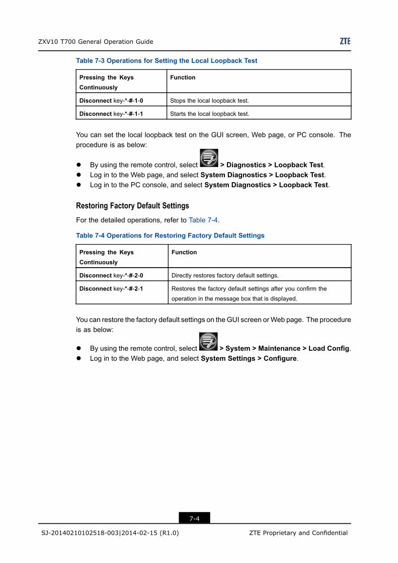
ZXV10 T700 General Operation Guide
Table 7-3 Operations for Setting the Local Loopback Test
Pressing the KeysContinuously
Function
Disconnect key-*-#-1-0 Stops the local loopback test.
Disconnect key-*-#-1-1 Starts the local loopback test.
You can set the local loopback test on the GUI screen, Web page, or PC console. Theprocedure is as below:
l By using the remote control, select > Diagnostics > Loopback Test.l Log in to the Web page, and select System Diagnostics > Loopback Test.l Log in to the PC console, and select System Diagnostics > Loopback Test.
Restoring Factory Default SettingsFor the detailed operations, refer to Table 7-4.
Table 7-4 Operations for Restoring Factory Default Settings
Pressing the KeysContinuously
Function
Disconnect key-*-#-2-0 Directly restores factory default settings.
Disconnect key-*-#-2-1 Restores the factory default settings after you confirm the
operation in the message box that is displayed.
You can restore the factory default settings on the GUI screen orWeb page. The procedureis as below:
l By using the remote control, select > System > Maintenance > Load Config.l Log in to the Web page, and select System Settings > Configure.
7-4
SJ-20140210102518-003|2014-02-15 (R1.0) ZTE Proprietary and Confidential
FiguresFigure 1-1 Conference Flow for New Users .............................................................. 1-1
Figure 1-2 Main Screen .......................................................................................... 1-11
Figure 1-3 ZTE PC Console Dialog Box ................................................................. 1-22
Figure 3-1 PIP mode............................................................................................... 3-10
Figure 3-2 Selecting the Secondary Video Output................................................... 3-16
Figure 6-1 Logo Uploading ...................................................................................... 6-4
Figure 6-2 Logo Page .............................................................................................. 6-5
I
SJ-20140210102518-003|2014-02-15 (R1.0) ZTE Proprietary and Confidential
Figures
This page intentionally left blank.
II
SJ-20140210102518-003|2014-02-15 (R1.0) ZTE Proprietary and Confidential
TablesTable 1-1 Operation Reference ................................................................................. 1-1
Table 1-2 Typical Application Scenario of Each Conference Control Mode ................ 1-2
Table 1-3 Operations for Setting Date and Time ....................................................... 1-5
Table 1-4 Parameter Descriptions for Terminal Display Setting ................................ 1-5
Table 1-5 Parameter Descriptions for IP Settings ...................................................... 1-6
Table 1-6 Operations for Setting the Preferred Protocol ........................................... 1-7
Table 1-7 Parameter Descriptions for H.323 Setting ................................................. 1-7
Table 1-8 Parameter Descriptions for SIP Setting ..................................................... 1-8
Table 1-9 Parameter Descriptions for Call Address Setting .................................... 1-11
Table 1-10 Operations for Making a Call ................................................................ 1-12
Table 1-11 Parameter Descriptions for Call Parameter Setting ............................... 1-12
Table 1-12 Operations for Calling a Terminal From the Address Book Screen.............................................................................................................. 1-13
Table 1-13 Icon Descriptions for the Multipoint Conference .................................... 1-13
Table 1-14 Icon Descriptions for the Multipoint Conference With an EmbeddedMCU ..................................................................................................... 1-14
Table 1-15 Parameter Descriptions for SIP Configuration ....................................... 1-17
Table 1-16 Operations for Calling the Microsoft Lync .............................................. 1-17
Table 1-17 Operations for Disconnecting a Call ...................................................... 1-18
Table 1-18 Operations for Managing Login Information ........................................... 1-22
Table 2-1 Operations for Adjusting Volume With the Remote Control ........................ 2-1
Table 2-2 Operations for Adjusting Volume from the Web Page ................................ 2-1
Table 2-3 Operations for Adjusting Volume from the PC Console .............................. 2-2
Table 2-4 Operations for Adjusting Audio In with the Remote Control ....................... 2-3
Table 2-5 Operations for Adjusting Audio In from the Web Page ............................... 2-3
Table 2-6 Operations for Adjusting Audio In from the PC Console............................. 2-3
Table 3-1 Operations for Adjusting the Local Camera with the Remote Control ........... 3-1
Table 3-2 Adjusting the Local Camera from the Web Page........................................ 3-2
Table 3-3 Adjusting the Remote Camera................................................................... 3-4
Table 3-4 Operations for Presetting the Position of the Local/Remote Camera ........... 3-5
Table 3-5 Operations for Presetting the Position of the Camera ................................ 3-5
Table 3-6 Parameter Descriptions For Camera Setting ............................................. 3-7
III
SJ-20140210102518-003|2014-02-15 (R1.0) ZTE Proprietary and Confidential
ZXV10 T700 General Operation Guide
Table 3-7 Descriptions for Terminal State Icons ...................................................... 3-11
Table 3-8 Descriptions for Terminal Audio Icons ..................................................... 3-12
Table 3-9 Descriptions for Terminal Connection Icons ............................................ 3-12
Table 3-10 Descriptions for Display Modes ............................................................ 3-14
Table 3-11 Parameter Descriptions for Video Output Port Setting ........................... 3-15
Table 3-12 Operations for Setting Display Mode ..................................................... 3-16
Table 3-13 Parameter Descriptions for Video In Setting ......................................... 3-18
Table 3-14 Parameter Description Video In Interface Setting .................................. 3-18
Table 3-15 Operations for Selecting the Local/Remote Primary Video Source withthe Remote Control ................................................................................ 3-20
Table 3-16 Operations for Selecting the Local/Remote Primary Video Source fromthe Web page ........................................................................................ 3-20
Table 4-1 Operations for Applying and Releasing Chairman on the RemoteControl ..................................................................................................... 4-2
Table 4-2 Operations for Applying and Releasing Chairman from the PC Console................................................................................................................ 4-2
Table 4-3 Descriptions for Broadcast Source Comparison ........................................ 4-3
Table 4-4 Operations for Selecting the Broadcast Source ........................................ 4-3
Table 4-5 Operations for Viewing Other Conference Sites ........................................ 4-4
Table 4-6 Operations for Controlling Conference Sound ........................................... 4-5
Table 4-7 Icon Descriptions ...................................................................................... 4-6
Table 5-1 Descriptions for Presentation Functions..................................................... 5-1
Table 5-2 Operations for Managing a Presentation with the Remote Control ............ 5-3
Table 5-3 Operations for Managing a Presentation on the Web Page ....................... 5-3
Table 5-4 Operations for Managing a Presentation on the PC Console ..................... 5-4
Table 5-5 Operations for Displaying Presentation...................................................... 5-4
Table 6-1 Descriptions for Volume Display Modes .................................................... 6-1
Table 6-2 Descriptions for Call Answering Modes ..................................................... 6-6
Table 7-1 Parameter Descriptions for Network Test Setting ...................................... 7-2
Table 7-2 Operations for Switching the Display 1 Video Output ................................. 7-3
Table 7-3 Operations for Setting the Local Loopback Test......................................... 7-4
Table 7-4 Operations for Restoring Factory Default Settings ..................................... 7-4
IV
SJ-20140210102518-003|2014-02-15 (R1.0) ZTE Proprietary and Confidential
GlossaryADSL- Asymmetric Digital Subscriber Line
DHCP- Dynamic Host Configuration Protocol
DNS- Domain Name Server
GK- Gate Keeper
IP- Internet Protocol
MCU- Multipoint Control Unit
PPPoE- Point to Point Protocol over Ethernet
TCP- Transmission Control Protocol
TLS- Transport Layer Security
UDP- User Datagram Protocol
V
SJ-20140210102518-003|2014-02-15 (R1.0) ZTE Proprietary and Confidential


