38 CT-1 TOROIDAL CURRENT TRANSFORMERS The CT series toroidal transformers allow to sense the leaking currents to earth. These transformers have been designed to be coupled to the maximum earth leakage current relays of the ELR series. The T/T’s should be installed upstream of the lines or loads to be protected and/or supervised. All active wires (phase and neutral) of the three phase or single phase lines should pass through the internal core of the transformers. It senses, in this way, the cur- rents vectorial addition, in order to transmit the earth leakage cur- rent to te secondary. For further applications of the CT toroidal transformers, please re- fer tao the specific documentation ( I.e. The sensing of the earth leakage current on the distribution transformers). The current T/T’s are made of an optimum quality magnetic core, which allows to detect leakage currents of a very low value even. There are two windings coupled in the core, one to detect the si- gnal of a leakage in the line ( to be sent to the relay), and the other for performing the Test. The eventual Test which uses this second winding is performed through various specific ELR’s types. A signal from the ELR is sent to the Test winding. This signal generates a flow equivalent to a leakage, which is detected by other winding and resent to the relay and makes it to trip. The selection of the transformer should be made on basis of the dimensions of the wires or bars that should pass through its inner hole. There are split core types available, which allow their instal- lation without disconnecting the actual wiring. CT-1/415 CTD-1/28 CT-1/210 CTA-1/210 CT-1/35, CT-1/60, CT-1/80, CT-1/110, CT-1/160, CTA-1/160 GENERALITY
Transcript
38
CT-1TOROIDAL CURRENT TRANSFORMERS
The CT series toroidal transformers allow to sense the leaking currents to earth. These transformers have been designed to be coupled to the maximum earth leakage current relays of the ELR series.The T/T’s should be installed upstream of the lines or loads to be protected and/or supervised. All active wires (phase and neutral) of the three phase or single phase lines should pass through the internal core of the transformers. It senses, in this way, the cur-rents vectorial addition, in order to transmit the earth leakage cur-rent to te secondary.For further applications of the CT toroidal transformers, please re-fer tao the specific documentation ( I.e. The sensing of the earth leakage current on the distribution transformers).
The current T/T’s are made of an optimum quality magnetic core, which allows to detect leakage currents of a very low value even. There are two windings coupled in the core, one to detect the si-gnal of a leakage in the line ( to be sent to the relay), and the other for performing the Test. The eventual Test which uses this second winding is performed through various specific ELR’s types. A signal from the ELR is sent to the Test winding. This signal generates a flow equivalent to a leakage, which is detected by other winding and resent to the relay and makes it to trip. The selection of the transformer should be made on basis of the dimensions of the wires or bars that should pass through its inner hole. There are split core types available, which allow their instal-lation without disconnecting the actual wiring.
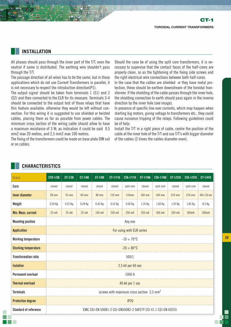
Inner diameter 28 mm 35 mm 60 mm 80 mm 110 mm 110mm 160 mm 160 mm 210 mm 210 mm 400 x 150 mm
Weight 0,20 Kg 0,22 Kg 0,28 Kg 0,45 Kg 0,52 Kg 0,60 Kg 1,35 Kg 1,60 Kg 1,45 Kg 1,85 Kg 8,3 Kg
Min. Meas. current 25 mA 25 mA 25 mA 100 mA 250 mA 250 mA 250 mA 500 mA 250 mA 500mA 500mA
Mounting position Any one
Application For using with ELR series
Working temperature -10 ÷ 70°C
Stocking temperature -20 ÷ 80°C
Transformation ratio 500/1
Isolation 2,5 kV per 60 sec
Permanent overload 1000 A
Thermal overload 40 kA per 1 sec
Terminals screws with maximum cross section 2,5 mm2
Protection degree IP20
Standard of reference EMC CEI-EN 50081-2 CEI-EN50082-2 SAFETY CEI 41.1 CEI-EN 60255
INSTALLATION
All phases should pass through the inner part of the T/T, even the neutral if same is distributed. The earthing wire shouldn’t pass through the T/T. The passage direction of all wires has to be the same, but in those applications which do not use Current Transformers in parallel, it is not necessary to respect the introduction direction(P1). The output signal should be taken from terminals 1 (S1) and 2 (S2) and then connected to the ELR for its measure. Terminals 3-4 should be connected to the output test of those relays that have this feature available, otherwise they would be left without con-nection. For this wiring it is suggested to use shielded or twisted cables, placing them as far as possible from power cables. The minimum cross section of the wiring cable should allow to have a maximum resistance of 3 W; as indication it could be said 0,5 mm2 max 20 metres, and 2,5 mm2 max 100 metres.The fixing of the transformers could be made on base plate DIN rail or on cables.
Should the case be of using the split core transformers, it is ne-cessary to supervise that the contact faces of the half-cores are properly clean, so as the tightening of the fixing side screws and the right electrical wire connections between both half-cores.In the case that the cables are shielded or they have metal pro-tection, these should be earthen downstream of the toroidal tran-sformer. If the shielding of the cable passes through the inner hole, the shielding connection to earth should pass again in the inverse direction by the inner hole (see image).In presence of specific line over currents, which may happen when starting big motors, giving voltage to transformers etc., they could cause nuisance tripping of the relays. Following guidelines could be of help:Install the T/T in a right piece of cable, centre the position of the cable at the inner hole of the T/T and use T/T’s with bigger diameter of the cables (2 times the cables diameter even).
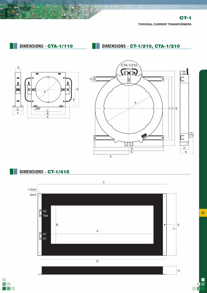
CT-1/210 CTA-1/210le dimensioni dei modelli CT-1/210 e CTA-1/210 sono identiche
*asole di fissaggio disponibili solo sui modelli CT-1/160 e CTA-1/160 Le dimensioni dei modelli CT-1/160 e CTA-1/160 sono identiche
CTA-1/210
F G
H
KB
D
CTD-1/28Residual current transformer
A
CTD-1/28
montaggio su profilato 35mm secondo DIN 50022 3 moduli da 17,5 mm
25
C
E
S1S1
S2Test
1,5mm
3mm
H
A
B
D
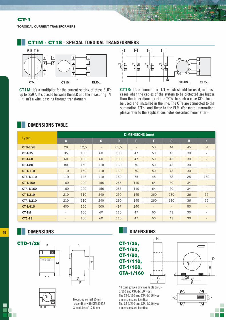
t ypeDIMENSIONS (mm)
A B C D E F G H K
CTD-1/28 28 52,5 - 85,5 - 58 44 45 54
CT-1/35 35 100 60 100 47 50 43 30 -
CT-1/60 60 100 60 100 47 50 43 30 -
CT-1/80 80 150 110 160 70 50 43 30 -
CT-1/110 110 150 110 160 70 50 43 30 -
CTA-1/110 110 145 110 150 75 45 38 25 180
CT-1/160 160 220 156 236 110 64 50 34 -
CTA-1/160 160 220 156 236 110 64 50 34 -
CT-1/210 210 310 240 290 145 260 280 36 55
CTA-1/210 210 310 240 290 145 260 280 36 55
CT-1/415 400 150 500 497 240 - - 50 -
CT-1M - 100 60 110 47 50 43 30 -
CT1-1S - 100 60 110 47 50 43 30 -
DIMENSIONS TABLE
CT-1TOROIDAL CURRENT TRANSFORMERS
CT1M: It’s a multiplier for the current setting of those ELR’s up to 250 A. It’s placed between the ELR and the measuring T/T ( It isn’t a wire passing through transformer)
CT1S: It’s a summation T/T, which should be used, in those cases when the cables of the system to be protected are bigger than the inner diameter of the T/T’s. In such a case Ct’s should be used and installed in the line. The CT’s are connected to the summation T/T’s and these to the ELR. (For more information, please refer to the applications notes described hereinafter).
DIMENSIONS DIMENSIONS
CT1M - CT1S - SPECIAL TOROIDAL TRANSFORMERS
* Fixing groves only available on CT-1/160 and CTA-1/160 typesThe CT-1/160 and CTA-1/160 type dimensions are identicalThe CT-1/210 and CTA-1/210 type dimensions are identical
Mounting on rail 35mm according with DIN 500223 modules of 17,5 mm
APPLICATION NOTE FOR EARTH LEAKAGE RELAYS ELR SERIES
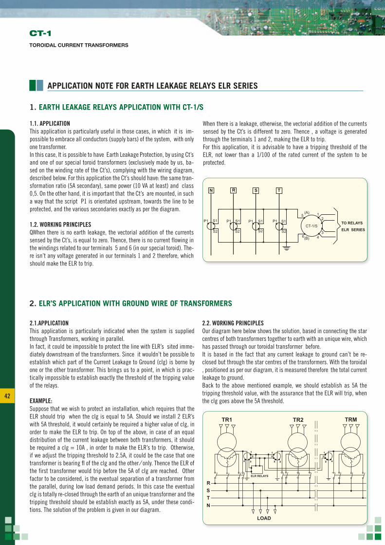
1.1. APPLICATIONThis application is particularly useful in those cases, in which it is im-possible to embrace all conductors (supply bars) of the system, with only one transformer.In this case, It is possible to have Earth Leakage Protection, by using Ct’s and one of our special toroid transformers (exclusively made by us, ba-sed on the winding rate of the Ct’s), complying with the wiring diagram, described below. For this application the Ct’s should have: the same tran-sformation ratio (5A secondary), same power (10 VA at least) and class 0,5. On the other hand, it is important that the Ct’s are mounted, in such a way that the script P1 is orientated upstream, towards the line to be protected, and the various secondaries exactly as per the diagram.
1.2. WORKING PRINCIPLESQWhen there is no earth leakage, the vectorial addition of the currents sensed by the Ct’s, is equal to zero. Thence, there is no current flowing in the windings related to our terminals 5 and 6 (in our special toroid). The-re isn’t any voltage generated in our terminals 1 and 2 therefore, which should make the ELR to trip.
When there is a leakage, otherwise, the vectorial addition of the currents sensed by the Ct’s is different to zero. Thence , a voltage is generated through the terminals 1 and 2, making the ELR to trip.For this application, it is advisable to have a tripping threshold of the ELR, not lower than a 1/100 of the rated current of the system to be protected.
2.1.APPLICATIONThis application is particularly indicated when the system is supplied through Transformers, working in parallel.In fact, it could be impossible to protect the line with ELR’s sited imme-diately downstream of the transformers. Since it wouldn’t be possible to establish which part of the Current Leakage to Ground (clg) is borne by one or the other transformer. This brings us to a point, in which is prac-tically impossible to establish exactly the threshold of the tripping value of the relays.
EXAMPLE:Suppose that we wish to protect an installation, which requires that the ELR should trip when the clg is equal to 5A. Should we install 2 ELR’s with 5A threshold, it would certainly be required a higher value of clg, in order to make the ELR to trip. On top of the above, in case of an equal distribution of the current leakage between both transformers, it should be required a clg = 10A , in order to make the ELR’s to trip. Otherwise, if we adjust the tripping threshold to 2.5A, it could be the case that one transformer is bearing fl of the clg and the other ⁄ only. Thence the ELR of the first transformer would trip before the 5A of clg are reached. Other factor to be considered, is the eventual separation of a transformer from the parallel, during low load demand periods. In this case the eventual clg is totally re-closed through the earth of an unique transformer and the tripping threshold should be establish exactly as 5A, under these condi-tions. The solution of the problem is given in our diagram.
2.2. WORKING PRINCIPLESOur diagram here below shows the solution, based in connecting the star centres of both transformers together to earth with an unique wire, which has passed through our toroidal transformer before.It is based in the fact that any current leakage to ground can’t be re-closed but through the star centres of the transformers. With the toroidal , positioned as per our diagram, it is measured therefore the total current leakage to ground. Back to the above mentioned example, we should establish as 5A the tripping threshold value, with the assurance that the ELR will trip, when the clg goes above the 5A threshold.
P1
N R S T
P1P1 P1S1 S1S1 S15
6
(A)
(B)
CT-1/S
1
TO RELAYS
ELR SERIES
2
34
S2 S2S2 S2
1. EARTH LEAKAGE RELAYS APPLICATION WITH CT-1/S
2. ELR’S APPLICATION WITH GROUND WIRE OF TRANSFORMERS
1 1 1
TR1 TR2 TRM
R
LOAD
STN
2 2 2
3
ELR RELAYS
3 34 4 4
CT-1TOROIDAL CURRENT TRANSFORMERS
43 43
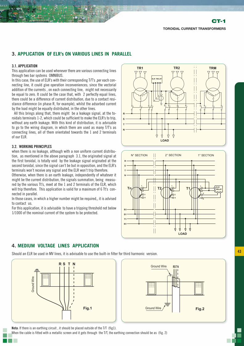
3.1. APPLICATIONThis application can be used whenever there are various connecting lines through two bar systems OMNIBUS.In this case, the use of ELR’s with their corresponding T/T’s ,per each con-necting line, it could give operation inconveniences; since the vectorial addition of the currents , on each connecting line, might not necessarily be equal to zero. It could be the case that, with 2 perfectly equal lines, there could be a difference of current distribution, due to a contact resi-stance difference (in phase R, for example), whilst the adsorbed current by the load might be equally distributed, in the other lines. All this brings along that, there might be a leakage signal, at the to-roidals terminals 1-2, which could be sufficient to make the ELR’s to trip, without any earth leakage. With this kind of distribution, it is advisable to go to the wiring diagram, in which there are used as many T/T’s as connecting lines, all of them orientated towards the 1 and 2 terminals of our ELR.
3.2. WORKING PRINCIPLESwhen there is no leakage, although with a non uniform current distribu-tion, as mentioned in the above paragraph 3.1, the originated signal at the first toroidal, is totally void by the leakage signal originated at the second toroidal, since the signal can’t be but in opposition, and the ELR’s terminals won’t receive any signal and the ELR won’t trip therefore.Otherwise, when there is an earth leakage, independently of whatever it might be the current distribution, the signals summation, being measu-red by the various Tt’s, meet at the 1 and 2 terminals of the ELR, which will trip therefore. This application is valid for a maximum of 6 Tt’s con-nected in parallel.In those cases, in which a higher number might be required,, it is advised to contact us.For this application, it is advisable to have a tripping threshold not below 1/1000 of the nominal current of the system to be protected.
Should an ELR be used in MV lines, it is advisable to use the built-in filter for third harmonic version.
3. APPLICATION OF ELR’s ON VARIOUS LINES IN PARALLEL
4. MEDIUM VOLTAGE LINES APPLICATION
CT-1TOROIDAL CURRENT TRANSFORMERS
1
ELR RELAY
TR1
R
S
T
N
TR2 TRM
23
4
LOAD
1 1 1
N° SECTION 2° SECTION 1° SECTION
R1
R
S1
S
T1
T
Tn T2 T1
N1
N
2 2 2
3 3 3
4 4 4
ELR RELAY
LOAD
R
Fig.1 Fig.2
Grou
nd W
ire
S T N RS T NGround Wire
Ground Wire
R
Fig.1 Fig.2
Grou
nd W
ire
S T N RS T NGround Wire
Ground Wire
Nota: If there is an earthing circuit , it should be placed outside of the T/T (fig1).When the cable is fitted with a metallic screen and it gets through the T/T, the earthing connection should be as (fig. 2)


![Parallelism, Multicore, and Synchronization · sw t1, s1, 4 # store A[i+1] addi s1, s1, +8 # increment pointer bne s1, s3, Loop # continue if s1!=end ALU/branch slot Load/store slot](https://static.documents.pub/doc/80x56/5f58ee0e112d542f8b3381fe/parallelism-multicore-and-sw-t1-s1-4-store-ai1-addi-s1-s1-8-increment.jpg)


