Laboratory of Optics Photonics and Quantum Electronics Department of Microelectronics and Applied PhysicsRoyal Institute of Technology (KTH) Electrum 229 16440 Kista Sweden
Corresponding author minkthse
Received August 3 2009 accepted August 12 2009posted August 25 2009 (Doc ID 115005) published September 15 2009
A systematic study on a generalized compensated bilayer structure is presented based on transformation op-tics A compensated bilayer can be constructed through a general transformation plus a coordinate inversionbased on a single layer in the electromagnetic (EM) space Two outer boundaries of the obtained bilayer aremapped from the same surface Such a bilayer has an optically zero volume (nihility) regardless of the materialcomposition in the original single layer This fact directly leads to the property of invariant scattering A bi-layer is also able to transfer the EM field from one side to the other with a scaling factor which is determinedby how the two side boundaries are mapped For a properly chosen background it is possible to achieve perfectoptical imaging Extensive numerical examples are given to demonstrate these identified properties and ap-plications Our study provides a more complete understanding of this class of transformation media by con-sidering general geometries and arbitrary material properties copy 2009 Optical Society of America
OCIS codes 2303205 2602110 2905839
ademi
cefivniWecltrcTmfabbntsghlfifl
INTRODUCTIONransformation optics provides a flexible way to designhe so-called transformation media to control electromag-etic (EM) fields or light [1ndash27] Theoretically transfor-ation optics stems from the form-invariance property ofaxwellrsquos equations in any geometrical space [1ndash6] Prac-
ically the obtained transformation media can be con-tructed with the help of metamaterial technology7ndash1328ndash31] The space where the transformation mediare implemented is called the transformed space or physi-al space The material parameters of transformation me-ia are obtained easily via tensor calculations [5] Theight trajectories in the transformed space and in theriginal space are interconnected via a simple coordinateapping function [5] A typical application of transforma-
ion optics is invisibility cloaks [1ndash1214ndash17] Also manyther applications such as beam shifters and splitters18] field rotators [19] EM wormholes [20] superlenses22ndash24] super scatterers [2526] optical illusion devices27] and transmutation of device singularities [1321] areroposedIn [32] complementary media were used to refer to two
djacent slab layers with equal thickness and opticallyffsetting media ie with material parameters of theame magnitude but different sign Similar media werelso proposed in [33] The significance of such complemen-ary media lies in their capability to transfer EM fieldserfectly from one side to the other side of the bilayer Theerfect lens originally proposed by Pendry [34] and theerfect lens made of indefinite media [35] are all withinhe scope of the complementary media In a recent paper4] it was found that transformation optics provides alear geometrical interpretation of Pendryrsquos perfect slabens In a previous paper by the current authors we took
0740-322409120B39-11$1500 copy 2
dvantage of transformation optics and applied it to theesign of generalized complementary media in slab geom-try [23] It was noticed that the two layers of a comple-entary media in general can be of unequal thicknesses
e be made of inhomogeneous indefinite materialsIn the present paper we further extend the concept of
omplementary media to bilayers in arbitrary 3D geom-tries by using transformation optics Similarly to ourndings in [23] the material parameters of two indi-idual layers of the bilayer do have different sign but notecessarily the same magnitude In addition the material
n each layer can contain anisotropy and inhomogeneitye refer to such bilayer structures as compensated bilay-
rs The bilayer structures are broadly divided into twoategories according to their geometrical properties a bi-ayer of the first type separates the background space intowo distinct regions a bilayer of the second type is sur-ounded by one continuous background The slab-shapedompensated bilayers [233233] belong to the first typehe two outer surfaces of a compensated bilayer areapped from the same surface in the EM space There-
ore the bilayer is optically nonexistent and the EM fieldt one of its surfaces is related to that at the other surfacey a scaling factor This feature is called the nihility of ailayer [33] In this paper we will analytically prove theihility of a general 3D bilayer deduced from transforma-ion optics The nihility feature leads directly to the con-equence of invariant scattering of a bilayer If the back-round material of the bilayer is properly chosen we canave the most important application of a compensated bi-
ayer ie superlensing [232432ndash35] That is the EMeld pattern on one side of the bilayer is perfectly trans-erred to the other side Besides imaging compensated bi-ayers can also have applications for providing invisibility
009 Optical Society of America
cidcts
2AClLibe
tbdccf
shbistiooraol
bsbioitpaslofstcbf
Fs(trt
Fcsth
B40 J Opt Soc Am BVol 26 No 12 December 2009 Yan et al
loaking [17] and optical illusions [25ndash27] Cloaking andllusion applications using the bilayer concept have beeniscussed previously in [1727] In this paper we will fo-us on the effects of perfect imaging and invariant scat-ering Extensive numerical examples will be given toupport our arguments
COMPENSATED BILAYER STRUCTURE Geometry of the Compensated Bilayeronsider a bilayer structure embedded in a 3D space Two
ayers of such a bilayer are denoted as layer 1 and layer 2ayer 1 is defined by boundaries S1 and S3 while layer 2
s defined by boundaries S2 and S3 S3 is the commonoundary between two layers In Fig 1 we illustrate sev-ral examples of the bilayer structure
Compensated bilayers can be broadly classified intowo categories The classification is based on the types ofoundaries forming the bilayer The first type of boundaryivides the space into two regions This type of boundaryan be a closed surface (eg a spherical surface) a semi-losed surface (eg a cylindrical surface) or an open sur-ace (eg a flat surface) The second type of boundary is
ig 1 (Color online) Illustation of a bilayer structure (a) Slab-haped bilayer of type A (b) cylindrical-shaped bilayer of type Ac) a spherical-shaped bilayer of type B The bilayer structure ofype A is surrounded by two discontinous regions region I andegion II The bilayer structure of type B is surrounded by a con-inous region
urrounded by one continuous region of space such as onealf of a spherical surface For our particular problem theoundaries Si i=123 should belong to the same typen order to make the layers 1 and 2 have definitivehapes Accordingly we can classify bilayers into twoypes the first type of bilayer denoted as type A bilayers defined by the first type of boundaries the second typef bilayer denoted as type B bilayer is defined by the sec-nd type of boundaries The bilayer of type A is sur-ounded by two discontinous regions which are denoteds regions I and II The bilayer of type B is surrounded byne continous region In Fig 1 several examples of the bi-ayer for types A and B are plotted
The considered bilayer in physical space is constructedy folding a single layer of an arbitrary medium in EMpace After folding the bilayer is put into an arbitraryackground ldquoFoldingrdquo in the simplest case denotes andentity transformation plus a coordinate inversion Bothperations can also be accompanied by some other (lessmportant) coordinate changes such as displacement ro-ation and compression Without loss of generality in thisaper we assume that the first layer (layer 1) is based onn identity transformation of the single layer in the EMpace The second layer (layer 2) is obtained by foldingayer 1 with respect to boundary S3 Therefore the twouter boundaries S1 and S3 of the bilayer are mappedrom an identical boundary Two 2D examples of the con-truction processes for two bilayer structures are illus-rated in Figs 2(a) and 2(b) In Fig 2(a) it is seen that aylindrical compensated bilayer of type A is constructedy folding a single cylindrical layer in the radial directionrom the EM space r z to the physical space r z
ig 2 (Color online) (a) Illustration of the construction of aylindrical-shape compensated bilayer of type A by folding aingle cylindrical shell in the radial direction (b) Illustration ofhe construction of a compensated bilayer of type B by folding aalf cylinder in one Cartesian axis direction
Tritsapffl
BAestrfm
wddtepTfiis
cnt
w
M
w
w
b
T
Tcscfflt
memEEl
tm
wc
le
Yan et al Vol 26 No 12 December 2009 J Opt Soc Am B B41
wo background regions denoted as I and II are sepa-ated by the bilayer The transformation function for thenversion is expressed as r=hr In Fig 2(b) it is seenhat a compensated bilayer structure of type B is con-tructed by folding a half cylinder along one Cartesianxis direction from the EM space x1 x2 x3 to thehysical space x1 x2 x3 The inversion transformationunction is expressed as x1=hx1 When hx1 is a linearunction with slope of 1 the obtained bilayer has a cy-indrical shape
Material Parameters of the Compensated Bilayerssume that layer 1 in the EM space has material param-ters and The Cartesian coordinates in the EMpace are denoted as x1 x2 x3 which are transformedo coordinates x1 x2 x3 in the physical space The mate-ial parameters of the transformed bilayer ie the trans-ormation medium are determined by certain transfor-ation principles to be introduced in the followingMaxwellrsquos equations in Cartesian coordinates
x1 x2 x3 are expressed as [5]
Dii = 0 Bii = 0
ijkEkj = minusBi
t ijkHkj =
Di
t
Di = ijEj Bi = ijHj 1
here Einsteinrsquos convention of summing over repeated in-ices is employed the subscript ldquoirdquo represents partialifferentiation to coordinate xi ijk is the permuta-ion symbol which is defined by ijk=1 if ijk is anven permutation of 123 ijk=minus1 if ijk is an oddermutation of 123 and ijk=0 for the other caseshe metric tensor denoted as gij which relates the in-nitesimal length measurement dS to coordinates dxi
e dS2=gijdxidxj is just gij=diag111 for Carte-ian coordinates
Consider a coordinate transformation from Cartesianoordinates x1 x2 x3 to arbitrary coordinatesx1 x2 x3 The metric tensor for the transformed coordi-ates is denoted as gij which relates the original metricensor gij via [5]
gij = iigijj
j 2
here the Jacobian matrix ii is written as
ii =
x1
x1
x1
x2
x1
x3
x2
x1
x2
x2
x2
x3
x3
x1
x3
x2
x3
x3
3
axwellrsquos equations in transformed coordinatesx1 x2 x3 can be written as [5]
Dii = 0 Bii = 0
ijkEkj = minusBi
t ijkHkj =
Di
t+ ji 4
ith
Ei = iiEi Hi = i
iHi
Di = ii Di Bi = i
i Bi 5
here ii = i
iminus1 and =detii
One can rearrange Eq (4) in the same form as Eq (1)y using scalings
Di = Di Bi = Bi 6
he new constitutive equations can be obtained as
Di = ijEi Bi = ijHi
ij = ii
ijjj ij = i
i ijjj 7
hus it shows that Maxwellrsquos equations in any arbitraryoordinates can be written in the same form as in Carte-ian coordinates However the EM parameters shouldhange their forms accordingly The media with trans-ormed material parameters ij and ij are called trans-ormation media The fields in the transformed media areinked to those in the original media by the coordinateransformation ie according to Eqs (5) and (6)
Equipped with the above knowledge we can calculateaterial parameters of compensated bilayer structures
asily Layer 1 in physical space has material parameters1= and 1= due to the identity transformation Theaterial parameters of layer 2 can be calculated throughq (7) Here it is noted that when the original layer inM space is composed of inhomogeneous media the bi-
ayer will also be composed of inhomogeneous mediaConsider the special example of a cylindrical bilayer of
ype A shown in Fig 2(a) It is calculated that layer 2 hasaterial parameters
2 =hr
r
dh
drdiag 1
dhdr
r
hr11 diag 1
dhdr
r
hr1
2 =hr
r
dh
drdiag 1
dhdr
r
hr11 diag 1
dhdr
r
hr1
8
here material parameters are expressed in cylindricaloordinates
Consider the special example of the compensated bi-ayer of type B shown in Fig 2(b) The material param-ters of layer 2 are derived as
2 =h
x1 diag 1
hx1 111 diag111
hx1
wo
3BTlbnblpe
dttHtvTtft
T
fT
w
s=ntondtea
t
BCtrnb
wgt=s
l
Frii
fioafHfcflfwsCnmtptb=Me=b
B42 J Opt Soc Am BVol 26 No 12 December 2009 Yan et al
2 =h
x1 diag111
hx11 diag 1
hx111 9
here material parameters are expressed in Cartesian co-rdinates
RELATIONSHIP OF FIELDS AT BILAYEROUNDARIEShe two outer boundaries S1 and S2 of a compensated bi-
ayer in the physical space are both mapped from theoundary S1 in the EM space Deployment of such coordi-ate mappings ensures a special feature of a compensatedilayer structure the fields at two boundaries of the bi-ayer connect with each other via the transformationrinciple as discussed in Section 2 In the following thexact field relationship between S1 and S2 will be derived
Let the EM fields at boundary S1 in the EM space beenoted by Ei HiS1
Since layer 1 is unchanged afterransformation the transformed fields at boundary S1 inhe physical space have EiS1
= EiS1and HiS1
= HiS1
ere we use ni t1i and t2i to denote the components ofhe unit normal vector and two orthogonal unit tangentialectors of the boundary S1 in the EM space respectivelyhe similar unit vectors at S1 in the physical space are
he same as those on S1 in the EM space The trans-ormed fields at S1 can be decomposed into normal andangential components as
En
Et1
Et2
S1
= En
Et1
Et2
S1
10
he magnetic fields have the same formNow consider boundary S2 in physical space The trans-
ormed fields are EiS2= i
iEiS1and HiS2
= iiHiS1
he electric fields at S2 can be written as
EiS2= i
init1it2iEn
Et1
Et2
S1
11
here we have made use of
EiS1= nit1it2i
En
Et1
Et2
S1
12
Consider the term iini t1i t2i on the right-hand
ide of Eq (11) One finds that iini t1i t2i
ni t1i t2i where ni t1i and t2i represent the compo-ents of the normal and tangential vectors at S2 in theransformed basis vectors ei with ei=i
i ei Since theriginal coordinates x1 x2 x3 are Cartesian coordi-ates one has e1= x1 e2= x2 and e3= x3 Then intro-uce t1i and t2i which represent the components of theangential vectors t1i and t2i in the basis vectors ei withi=gijej Thus one has t1it1i=t2it2i=1 t1it2i=t2it1i=0nd n t1i=n t2i=0 Multiplying both sides of Eq (11) by
i i
ni t1i t2iT where ni is defined as ni=ni to keep calcula-ion consistently in tensor form one has
ni
t1i
t2iEiS2=
nini nit1i nit2i
0 1 0
0 0 1
En
Et1
Et2
S1
13
y examining the three components of ni expressed inartesian basis vectors one can find that it represents
he normal direction of surface S2 Thus t1i and t2i rep-esent two different tangential directions of S2 sinceit1i=nit2i=0 and ni=ni With this information Eq (13)ecomes
En
Et1
Et2
S2
= niniN nit1iN nit2iN
0 1T1 0
0 0 1T2
En
Et1
Et2
S1
14
here En Et1 Et2S2represent the normal and the tan-
ential field components at S2 respectively which are de-ermined by ni t1i and t2i N is defined by Nn12+ n22+ n32 and T1 and T2 are defined in theame form but in terms of t1i and t2i respectively
By combining Eqs (10) and (14) the tangential field re-ationship between S1 and S2 is derived as
Et1S1= T1Et1S2
Et2S1= T2Et2S2
15
rom this equation we see that the fields at S1 and S2elate to each other by a scaling This field relationship isndependent of whether the bilayer is inhomogeneous an-sotropic
In the following it will be shown that the boundary-eld relationship Eq (15) is dependent only on M thene-to-one point mapping function from surface S1 to S2nd is independent of the domain transformation functionrom xi to xi This property will be used in Section 4ere it should be recalled that different transformation
unctions can share the same M This is similar to thease for obtaining an invisibility cloak where one has theexibility to choose either a linear or a nonlinear trans-ormation function as long as the outer cloak boundary al-ays is kept intact for the chosen transformation Con-
ider two points with infinitesimal distance dl denoted byand D on surface S1 Assume that the vector CD de-
oted by aidxi just lies in the direction of the vector t1i
t1i=t1i Thus one has t1i=aidxi dl Considering aapping M from S1 to S2 aidxi will become aidxi where
he values of aidxi are determined by the boundary map-ing M Thus one has t1i=aidxi dl This indicateshat the tangential direction t1i on S2 is determined onlyy the mapping M It follows that T1a1dx12+ a2dx22+ a3dx32 dl which also depends on
only The same procedures apply for t2i and T2 In thextreme case when S2 is equal to S1 one has t1i=t1i t2i
t2i and T1=T2=1 and Eq (15) is just the continuousoundary conditions
2
4AafroegcrFfbtmbaaITtat
sfifi(
bI
T(
Tabrns
ggignasrtrgIs
al
saist
Forgn
Fgri(w
Yan et al Vol 26 No 12 December 2009 J Opt Soc Am B B43
As an example considering the bilayer structure in Fig(a) one can easily calculate that
EzS1= EzS2
ES1=
b
aES2
HzS1= EzS2
HS1=
b
aES2
16
PROPERTIES AND APPLICATIONSs discussed above we know that the fields at two bound-ries of the bilayer relate to each other by a scaling In theollowing it will be shown that this special property willesult in the nihility of the bilayer That is an observerutside the bilayer can feel the same fields as nonexist-nce of the bilayer Consider an observer say Bob in re-ion I The scattering fields observed by him are as if theyome from a region denoted as region II connecting di-ectly with region I via boundary S1 This is illustrated inig 3(a) Region II can be obtained by making a trans-
ormation from region II while boundary S2 is mapped tooundary S1 according to the function Mminus1 Note thathere are many choices for region II since there existany spatial transformation functions sharing the same
oundary mapping function Mminus1 And the other wayround if Bob is in region II the fields observed by himre as if they are coming from a region denoted as region connecting directly with region II via boundary S2his is illustrated in Fig 3(b) Region I can be obtained
hrough a transformation based on region I with bound-ry S1 mapped to boundary S2 according to M Againhere are many choices for region I
To show the validity of the above statements we con-ider the case as shown in Fig 3(a) Assume that the EMelds in regions I and II are denoted as Ei
I HiI and
EiII Hi
II respectively It is known that the tangentialelds at boundaries S1 and S2 relate to each other via Eq
15) The transformed fields in region II are denoted as
ig 3 (Color online) For the bilayer structure of type A (a) anbserver in region I perceives the fields as if the fields were fromegion II connected directly with region I (b) An observer in re-ion II perceives the fields as if the fields were from region I con-ected directly with region II
EiII Hi
II which can be calculated from EiII Hi
II Sinceoundary S2 of region II maps to boundary S1 of regionI according to the mapping function Mminus1 we can have
Et1II S1
= 1T1Et1II S2
Et2II S1
= 1T2Et2II S2
17
his is derived similarly as for Eq (15) Combining Eqs15) and (17) one has
Et1II S1
= Et1I S1
Et2II S1
= Et2I S1
18
his indicates that the fields EiI Hi
I and EiII Hi
II canutomatically fulfill the continuous boundary conditionetween regions I and II Thus it is proved that Bob inegion I perceives the same fields as if region II is con-ected with region I directly When Bob is in region II aimilar argument can also be proved
For the bilayer structure of type B the background re-ion is connected However one can generate two back-round regions by introducing an extra boundary Thisdea is illustrated in Fig 4 Refering to Fig 4(a) the re-ion outside the extra boundary S4 and boundary S1 is de-oted as region I while the region inside the boundary S4nd S2 is denoted as region II Similarly to the bilayertructure of type A Bob in region III feels the fields as ifegion II I were connected to region III this is illus-rated in Figs 4(a) and 4(b) Conversely we can transformegion II I to region III without changing fields in re-ion III by attaching a compensated bilayer to regionII This mechanism has been deployed in [27] to demon-trate illusion optics
Having proved the nihility of a compensated bilayer were ready to discuss the following the property of a bi-ayer
Invariant scattering Scattering caused by a compen-ated bilayer with the same shape and the same bound-ry mapping function M remains the same regardless ofts material parameters Consider a compensated bilayertructure placed in an arbitrary background Owing tohe perfect nihility a change in the material parameters
ig 4 (Color online) By inducing an extra boundary S4 the re-ion outside the bilayer structure of type B can be separated intoegions I and II (a) An observer in region I perceives the fields asf the fields were from region II connected directly with region Ib) An observer in region II perceives the fields as if the fieldsere from region I connected directly with region II
oecIis
abcptpthfBtsts
t
maosIsfapHb
tiltBsogmvtImtcrdt
wwjg
l
ecf
5CAcbbdcaaiTxpopaba
hp=de[
wfiflvedtcatxatal
1Aflfq=ig1dtc[
B44 J Opt Soc Am BVol 26 No 12 December 2009 Yan et al
f the bilayer ie from a change in the material param-ters of the original single layer in EM space will nothange the field distributions in background regions I andI This indicates that the scattered field by the bilayer isndependent of the material parameters of the bilayertructure
It should be mentioned that the phenomenon of invari-nt scattering can be extended to active obstacles For theilayer of type A if a noise source is present in layer 1 aomplementary source can be placed in a correspondingosition in layer 2 to annihilate the radiation caused byhe source in layer 1 This can be classified as a separateroperty of the compensated bilayer referred to as ldquoradia-ion cancellationrdquo For the bilayer of type A this subjectas been studied in [23] However to our knowledge so
ar the subject has not been studied for the bilayer of type In fact we have noticed that the phenomenon of radia-
ion cancellation by the bilayer of type B is not always astraightforward as the case for the bilayer of type A De-ailed investigations of this phenomenon will be pre-ented in a future publication
In addition based on our above discussion one may findhe following applications for a compensated bilayer
Perfect imaging With the right choice of backgroundaterial one can transfer EM fields from one boundary ofcompensated bilayer to the other perfectly with or with-
ut a linear scaling To require zero reflection it is neces-ary for region I (II) to be perfectly matched with regionI I This in turn gives the required material relation-hip between regions I and II It is worth noting that per-ect imaging is even possible in the presence of passivend active obstacles [2332] If a passive scatterer isresent in the bilayer the image quality will be degradedowever one can put a complementary scatterer in theilayer to recover the imageOptical illusion An object appears as another object
o an observer in a different domain Consider an examplen which a scatterer is put inside region II of a type A bi-ayer structure as in Fig 2(a) Assume that region II hashe same material parameters as region I In this caseob in region I perceives the scatterer as a magnifiedcatterer in a background with the material parametersf region I since the scatterer will be magnified when re-ion II is transformed to region II Such an llusion ofagnification was previously discussed in [2526] Con-
ersely if the scatterer is in region I and region I hashe same material parameters as region II Bob in regionI will feel a shrunk scatterer in the background with theaterial parameters of region II For the bilayer struc-
ure of type B a similar phenomenon of optical illusionan also occur as discussed in [27] If the object is put inegion II (I) region II (I) is just the restoring medium asefined in [27] To an observer in region I (II) it appearshat an an object is present in region II I
Invisibility cloaking An object is made invisibleithout perturbing the incident fields For this purposee can put a compensating object to offset the original ob-
ect in a compensated structure To achieve invisibility re-ion I (II) should be impedance matched with region III This phenomenon has been well discussed in [17]
In the following we will focus on demonstrating the fol-owing properties and applications of compensated bilay-
rs perfect imaging and invariant scattering The appli-ations to optical illusion and invisibility cloaking can beound in [1725ndash27]
NUMERICAL ANALYSIS FOROMPENSATED BILAYER Slab-shaped Compensated Bilayer of Type A
ompensated bilayer in slab geometry can be constructedy an identity transformation plus a coordinate inversionased on a single slab layer Suppose that the bilayer un-er study is oriented perpendicular to x1 For ease of dis-ussion we assume that the surface S1 is at x1=a whereis a constant and the transformation concerns only x1
nd x1 The transformation function for the coordinatenversion is denoted by x1=hx1 with a negative slopehe left and right boundaries of the bilayer ie x1=a and1=b are both mapped from x1=a Layer 1 has materialarameters 1 and 1 which are the same as those of theriginal single slab Layer 2 has material parameters ex-ressed by Eq (9) since the folding function is the sames that in Fig 2(b) Consider two regions separated by theilayer Region I has the material parameters I and Ind region II has the material parameters II and IIAssume that the inversion transformation function
x1 is a linear function with a slope of minusp where0 From Eq (9) it is derived that 2minusp diagminus1p 1 11 diagminus1p 1 1 2=minuspiagminus1p 1 11 diagminus1p 1 1 When p=1 the abovequations describe exactly the complementary media in3233]
In [3233] it is stated that a slab compensated bilayerhen put in a homogenous background can transfer EMelds perfectly from one interface to the other without re-ections Here we see that transformation optics pro-ides a clear geometrical interpretation of this phenom-non In addition transformation optics enables theesign of a much broader class of compensated bilayershan those proposed in [3233] One can easily extend aompensated bilayer to the following situations (1) p1ndor (2) hx1 is a nonlinear function andor (3) theransformation function concerns all coordinates not only1 and x1 andor (4) the single slab in EM space containsrbitrary inhomogeneity anisotropy [23] This facilitateshe unification of a range of perfect previously studied im-ging devices including Pendryrsquos perfect lens the bilayerens made of indefinite media
Perfect Imagings discussed in Section 4 perfect imaging requires the re-ectionless condition That is region I (II) should be per-
ectly matched with region II I in impedance This re-uirement can be satisfied easily when 1=II and 1II since region II I can be obtained easily by shift-
ng region II (I) The simplest case is that background re-ions on both side are free space In addition when layeris also free space layer 2 would be a left-handed me-
ium with n=minus1 The obtained bilayer is none other thanhe perfect slab lens in [34] Since optical imaging forompensated bilayers in slab shape has been discussed in32] and more comprehensively in [23] here we will pro-
vtremti
BHtircfmrbp
a=ft
Iads
1Pmlgri=set
sh
o=
Ttsd=sgm
btwnlcl=Io=rt=minusminustata5mpw=tfbtmsTf
ords
Yan et al Vol 26 No 12 December 2009 J Opt Soc Am B B45
ide no further discussion It is meaningful to point outhat perfect imaging with free-space background in bothegions I and II is applicable only to compensated bilay-rs in slab geometry For all other bilayers backgroundaterials have to be chosen carefully in order to achieve
he reflectionless condition as will be shown in the follow-ng subsections
Cylindrical-Shaped Compensated Bilayer of Type Aere we numerically examine a compensated bilayer ob-
ained by transforming a cylindrical shell as illustratedn Fig 2(a) For ease of discussion we use cylindricalather than Cartesian coordinates The original cylindri-al coordinates are denoted as r z and the trans-ormed coordinates are denoted as r z The transfor-ation function concerns only r and r and is denoted as
=hr with a negative slope Layer 1 is in region arc while layer 2 is in region crb The relationship
etween material parameters in layers 1 and 2 is ex-ressed in Eq (8)Consider the case when and can be expressed di-
gonally in cylindrical coordinates ie 1=diag1r 1 1z and 1==diag1r 1 1z Then
rom Eq (8) the expressions for 2 and 2 can be reducedo
2 = diag hr
rhr1r
rhr
hr1
hrhr
r1z
2 = diag hr
rhr1r
rhr
hr1
hrhr
r1z 19
t is easily found that the material parameters in layers 1nd 2 should have different signs since hr0 andh dr0 This is a common requirement for a compen-ated bilayer
Perfect Imagingerfect imaging requires that region I be perfectlyatched with region II All free-space background is no
onger able to satisfy the requirement in this cylindricaleometry One can start by considering that regions I andegion II have identical material parameters Region IIs then transformed back to region II with boundary ra mapped to r=b The simplest transformation functionatisfying this boundary transformation condition is a lin-ar function expressed as r=ra b Under this linearransformation region II has material parameters
II = diag11a
bI diag11a
b
II = diag11a
bI diag11a
b 20
We consider the simplest case where region I is freepace In addition hr is a linear function expressed asr= rminusbcminusa cminusb+a Thus one has I=I=1 and
= =diag11 a b2
II II
If the original single layer is composed of free spacene obtains the material parameters of the bilayer as 11=1 and
2r = 2r =rc minus a + ca minus b
rc minus a
2 = 2 =rc minus a
rc minus a + ca minus b
2z = 2z =rc minus a2 + ca minus bc minus a
rc minus b2 21
he material parameters of layer 2 are all negative Whenhe slope of hr is 1 layer 1 and layer 2 will have theame thickness and the material parameters can be re-uced to 2r=2r= rminus2c r 2=2=r rminus2c and 2z2z= rminus2c r This is just the cylindrical superlenstudied in [24] This type of cylindrical superlens is analo-ous to Pendryrsquos slab superlens in superlensing perfor-anceIf layer 1 is composed of some indefinite medium (with
oth positive and negative tensor components in its ma-erial parameters) in EM space the compensated bilayerill accordingly be composed of indefinite media This sce-ario was previously studied by Smith and Schurig but
imited only to slab geometry [35] Here we propose aompensated bilayer lens made of indefinite media in cy-indrical geometry As a particular example we choose a15 b=05 and c= Region I is free space and regionI has material parameters II=II=diag119 Theriginal single layer is an indefinite medium with diag1minus11 and =diagminus111 By using a linearadial transformation function with a slope of 1 we ob-ain the material parameters of layers 1 and 2 as 1diag1minus11 and 1=diagminus111 2=diagrminus2 r r rminus2 rminus2 r and 2=diagminusrminus4 r r r4 rminus4 r We consider an EM wave propagating in
rminus plane with TE polarization (ie the E field is alonghe z direction) For this special polarization consider-tion the material parameters of region II can be reducedo II=9 and II=1 The material parameters of layers 1nd 2 relevant to the TE polarization are plotted in Figs(a) and 5(b) respectively We deploy the finite-elementethod from the commercial COMSOL Multiphysics
ackage to carry out numerical simulations In the full-ave simulation a line current source is positioned at (rminus155 ) near S1 The simulated electric field dis-
ribution is plotted in Fig 6 It is seen that the field per-ectly transfers from S1 to S2 almost without distortionut with a simple linear scaling An image of the source isherefore formed at S2 It should be noticed that for nu-erical simulations in this work all material parameters
maller than 1 are given a small imaginary part of 0006ihis is the reason behind the finite scattering perceivable
rom Fig 6For a cylindrical bilayer constructed using this method
nly one layer of the bilayers has gradient material pa-ameters One can however choose to construct a cylin-rical compensated bilayer by rolling up a slab compen-ated bilayer as in [3236] In that case both layers of the
oom
2Hifrdtbl
btdiifit
3Aoncnis[dcwaTafggAg(sFf
Fscstli
Fo
Fbminus
B46 J Opt Soc Am BVol 26 No 12 December 2009 Yan et al
btained cylindrical bilayer plus the background regionsutside and inside the bilayer all need to have gradientaterial parameters which is certainly not desirable
Invariant Scatteringere we will show that the scattering caused by a bilayer
s related only to its geometry and the boundary mappingunction M and is independent of the bilayer material pa-ameters as long as its construction follows the rules ad-ressed in this paper As a demonstration we examinehe scattering caused by the two cylindrical bilayers Oneilayer is as the same as studied in Fig 6 The other bi-ayer has the same geometrical parameters as in Fig 6
x1λ
x2 λ
minus2 0 2
minus2
0
2minus200
0
200
ig 6 (Color online) Electric field distribution for a line currentource located at (r=155 ) interacting with a cylindricalompensated bilayer composed of indefinite media The compen-ated bilayer lens has the same parameters as in Fig 5 excepthat material parameters smaller than 1 are all given a smalloss of 0006i Region II has material parameters of II=9 andII=1 The bilayer is outlined by solid lines The source and the
mage are denoted by an asterisk
1 125 1minus2
minus1
0
1
2
Mat
eria
lPar
amet
ers
rλ
micro31r
micro31θ
ε31z
(a)ig 5 (Color online) Material parameters of a cylindrical compf layer 1 (b) material parameters of layer 2
x1λ
x2 λ
minus2 0 2
minus2
0
2 minus
minus
0
1
2
(a)ig 7 (Color online) Electric field distribution for a plane wavilayer having the same geometrical parameters as in Fig2 r r rminus2 rminus2 r Regions I and II are free space The
ut has different material parameters as 1=1=1 and2=2=diagrminus2 r r rminus2 rminus2 r In both caseshe background regions I and II are free space The fieldistributions simulated as a plane wave incident from leftnfinity are shown in Figs 7(a) and 7(b) By comparison its observed that regions I and II have almost the sameeld distributions indicating identical scattering charac-eristics of the two bilayers
Optical Illusions discussed above if a scatterer is put in region II anbserver will feel as if the scattered field is from a mag-ified scatterer located in region II This has been dis-ussed in [2526] with lenses made of media with all-egative material components Conversely if a scatterer
s put in region I the observer in region II will feel ahrunk scatterer This phenomenon has been indicated in32] but with no numerical examples given Here we willemonstrate this phenomenon numerically with a con-rete example Region I is transformed from region Ihich is restricted by the condition that region Irsquos bound-ry S1 ie r=a be transformed to the boundary r=bhe simplest transformation satisfying this restriction islinear function with r=rb a Using this transformation
unction one can easily get the material parameters of re-ion I In our example the material parameters of re-ions I II and the bilayer are the same as that in Fig 6perfect electric conductor (PEC) cylinder is added in re-
ion I The cylinder has a radius of 15 and is located atr=3 ) The simulated electric field distributionubject to a line current source at the origin is plotted inig 8(a) Transforming region I to I with a linear trans-
ormation function r=r 3 one finds that the correspond-
05 075 1minus4
minus2
0
2
4
Mat
erai
lPar
amet
ers
rλ
micro32r
micro32θ
ε32z
)d bilayer composed of indefinite media (a) Material parameters
x1λ
xλ
minus2 0 2
minus2
0
2 minus2
minus1
0
1
2
)left infinity interacting with (a) the bilayer as in Fig 6 (b) thedifferent material parameters 1=1=1 and 2=2=diagr
r is outlined by solid lines
5(b
ensate
2
1
2
(be from6 butbilaye
iog=pswa8t
C
1Hllaetzrgwib
dminusmminus=s
sttn
2Fahspidep+d=idbtbs
6Iomvptttmcs
FbFr
Fpcsb+minus=ss
Yan et al Vol 26 No 12 December 2009 J Opt Soc Am B B47
ng PEC cylinder changes to a smaller size with a radiusf 05 and is located at (r= ) The free-space back-round in region I changes to a medium with I=Idiag119 which is as the same as in region II For TEolarization the material parameters reduce to I=9 and
I=1 Thus an observer in region II will feel a shrunkcatterer in a medium with b=9 and b=1 To verify thise simulate the interaction of the same source with suchshrunk scatterer placed in a background with b=9 andb=1 The resulted field distribution is plotted in Fig(b) Comparing Figs 8(a) and 8(b) one can notice almosthe same field distributions as in region II
Compensated Bilayer of Type B
Perfect Imagingere we consider a square-shaped bilayer of type B as il-
ustrated in Fig 9(a) Referring to the figure layer 1 andayer 2 are connected through the squarersquos diagonal with
length of Layer 2 is obtained by folding layer 1 lin-arly in the x1 direction Thus the material parameters ofhe bilayer should fulfill 1=minus2 and 1=minus2 To achieveero reflection region I should be perfectly matched withegion II [see Fig 3(a)] To find an appropriate back-round combination we may start with an EM spacehere regions I and II are both free space fulfilling the
mpedance matching condition Region II can be obtainedy a compression of region II For our example this can
minus05 0 05
minus050
05
x1 λ
x2 λ
minus4 minus2 0 2
minus2
0
2minus20minus100100
RegionII
(a)ig 8 (Color online) Electric field distribution for a line currenedded in region I (b) a PEC cylinder in the background with big 6 The PEC cylinder in (a) located at (r=3 ) has a raadius of 05 The bilayer and the PEC cylinder are outlined by
x1λ
x2 λ
minus2 0 2minus2
minus1
0
1
2
minus400
minus200
0
200
(b)(a)
ig 9 (Color online) (a) Illustration of a square-shaped com-ensated bilayer of type B (b) Electric field distribution for a lineurrent source J1=a13x1minus0313x2minus03x3 interacting with thequare-shaped compensated bilayer as in (a) The compensatedilayer has material parameters 1=1=1 and 2=2=minus10006i Region II has material parameters II=II= 5minus30320002 for the half part of x20 and II=II530320002 for the half part of x20 Region I is freepace The bilayer and region II are outlined by solid lines theource and the image are denoted by
one with transformation functions x1=12x1+3205
absx2 x2=x2 and x3=x3 In this way we obtain theaterial parameters of region II as II=II= 5minus30320002 for the half part of x20 and II=II530320002 for the half part of x20 In theimulation we take the bilayer material parameters as1=1=1 and 2=2=minus1+0006i A line current source iset to be J=a13x1minus0313x2minus03z The simulated elec-ric field distribution is plotted in Fig 9(b) It is observedhat the field transfers from boundary S1 to boundary S2early perfectly and an image is formed at boundary S2
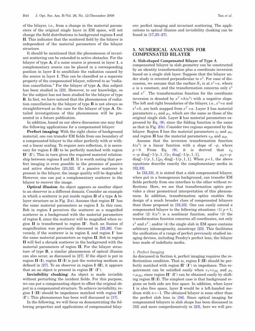
Invariant Scatteringor this case we consider a compensated bilayer of type Bs illustrated in Fig 2(b) The inversion mapping functionx1 is a linear function with a negative slope of 1 Thehape of the bilayer is just a perfect clinder The materialarameters of the bilayer can be obtained from Eq (9)e 1=minus2 and 1=minus2 The invariant scattering can beemonstrated with two bilayers sharing the same geom-try One bilayer has a radius of 05 and has materialarameters 1=4 and 1=1 1=minus4+0006i and 1=minus10006i The other bilayer has the same geometry but hasifferent material parameters as 1=3 and 1=3 and 2minus3+0006i and 2=minus3+0006i Both bilayers are placed
n a free-space background When a plane wave is inci-ent from left infinity the field distributions for the twoilayers are as plotted in Figs 10(a) and 10(b) respec-ively By comparison it is observed that the field distri-utions in the free-space background are almost theame
CONCLUSIONSn this paper we have presented a comprehensive studyn generalized compensated bilayers based on transfor-ation optics The compensated bilayers are broadly di-
ided into two categories according to their geometricalroperties Both types of compensated bilayers can be ob-ained by making a folding-style coordinate transforma-ion based on a single material layer in the EM space Thewo outer boundaries of a compensated bilayer are bothapped from a single surface in the EM space Therefore
ompensated bilayers exhibit nihility an external ob-erver can feel the same fields as nonexistence of the bi-
x1 λ
x2 λ
minus4 minus2 0 2
minus2
0
2minus200minus1000100
minus05 0 05
minus050
05
RegionII
)ce located at the origin interacting with (a) a PEC cylinder em-b=1 The compensated bilayer has the same parameters as in
f 15 The PEC cylinder in (b) located at at (r= ) has alines
00
(bt sour
=9 anddius osolid
lscfpvccp
ATSC
R
1
1
1
1
1
1
1
1
1
1
2
2
2
2
2
2
2
2
2
2
3
Fwo+
B48 J Opt Soc Am BVol 26 No 12 December 2009 Yan et al
ayer This feature leads to the phenomenon of invariantcattering When the background is designed properly aompensated bilayer can transfer the EM field perfectlyrom one surface to the other without any scattering Thisroperty allows compensated bilayers to function as de-ices for achieving perfect imaging achieving invisibilityloaking and creating illusion optics Extensive numeri-al examples are presented to demonstrate the identifiedroperties and applications
CKNOWLEDGMENTShis work is supported by the Swedish Foundation fortrategic Research (SSF) and the Swedish Researchouncil (VR)
EFERENCES1 J B Pendry D Schurig and D R Smith ldquoControlling
1777ndash1780 (2006)3 U Leonhardt and T Tyc ldquoBroadband invisibility by non-
Euclidean cloakingrdquo Science 323 110ndash112 (2009)4 U Leonhardt and T G Philbin ldquoGeneral relativity in
electrical engineeringrdquo New J Phys 8 247 (2006)5 U Leonhardt and T G Philbin ldquoTransformation optics and
the geometry of lightrdquo httpwwwarXiv08054778v2[physics optics] 2008
6 M Yan W Yan and M Qiu ldquoInvisibility cloaking bycoordinate transformationrdquo in Progress in Optics Vol 52E Wolf ed (Elsevier 2008) Chap 4
7 D Schurig J J Mock B J Justice S A Cummer J BPendry A F Starr and D R Smith ldquoMetamaterialelectromagnetic cloak at microwave frequenciesrdquo Science314 977ndash980 (2006)
8 R Liu C Ji J J Mock J Y Chin T J Cui and D RSmith ldquoBroadband ground-plane cloakrdquo Science 323366ndash369 (2009)
9 J Valentine J Li T Zentgraf G Bartal and X ZhangldquoAn optical cloak made of dielectricsrdquo Nature Mater 8568ndash571 (2009)
0 L H Gabrielli J Cardenas C B Poitras and M LipsonldquoSilicon nanostructure cloak operating at opticalfrequenciesrdquo Nature Photon 3 461ndash463 (2009)
1 J H Lee J Blair V A Tamma Q Wu S J Rhee C JSummers and W Park ldquoDirect visualization of opticalfrequency invisibility cloak based on silicon nanorodarrayrdquo Opt Express 17 12922ndash12928 (2009)
2 I I Smolyaninov V N Smolyaninova A V Kildishev andV M Shalaev ldquoAnisotropic metamaterials emulated bytapered waveguides application to optical cloakingrdquo PhysRev Lett 102 213901 (2009)
x1λx2 λ
minus1 0 1
minus1
0
1 minus
0
3
(a)ig 10 (Color online) Electric field distribution for a plane wavhich has a radius of 05 and material parameters as 1=4 an
f type B which has the same geometry as in (a) but different m0006i The region outside the bilayer is free space The bilayer
3 Y G Ma C K Ong T Tyc and U Leonhardt ldquoAnomnidirectional retroreflector based on the transmutationof dielectric singularitiesrdquo Nature Mater 8 639ndash642(2009)
4 Z C Ruan M Yan C W Neff and M Qiu ldquoIdealcylindrical cloak perfect but sensitive to tinyperturbationsrdquo Phys Rev Lett 99 113903 (2007)
5 H S Chen B I Wu B L Zhang and J A KongldquoElectromagnetic wave interactions with a metamaterialcloakrdquo Phys Rev Lett 99 063903 (2007)
6 M Yan Z C Ruan and M Qiu ldquoCylindrical invisibilitycloak with simplified material parameters is inherentlyvisiblerdquo Appl Phys Lett 99 233901 (2007)
7 Y Lai H Y Chen Z Q Wang and C T ChanldquoComplementary media invisibility cloak that cloaksobjects at a distance outside the cloaking shellrdquo Phys RevLett 102 093901 (2009)
8 M Rahm S A Cummer D Schurig J B Pendry and DR Smith ldquoOptical design of reflectionless complex mediaby finite embedded coordinate transformationsrdquo Phys RevLett 100 063903 (2008)
9 H Y Chen and C T Chan ldquoTransformation media thatrotate electromagnetic fieldsrdquo Appl Phys Lett 90 241105(2007)
0 A Greenleaf Y Kurylev M Lassas and G UhlmannldquoElectromagnetic wormholes and virtual magneticmonopoles from metamaterialsrdquo Phys Rev Lett 99183901 (2007)
1 T Tyc and U Leonhardt ldquoTransmutation of singularities inoptical instrumentsrdquo New J Phys 10 115038 (2008)
2 A V Kildishev and V M Shalaev ldquoEngineering space forlight via transformation opticsrdquo Opt Lett 33 43ndash45(2008)
3 W Yan M Yan and M Qiu ldquoAchieving perfect imagingbeyond passive and active obstacles by a transformedbilayer lensrdquo Phys Rev B 79 161101 (2008)
4 M Yan W Yan and M Qiu ldquoCylindrical superlens by acoordinate transformationrdquo Phys Rev B 78 125113 (2008)
5 T Yang H Y Chen X D Luo and H R MaldquoSuperscatterer Enhancement of scattering withcomplementary mediardquo Opt Express 16 18545ndash18550(2008)
6 Y Luo J J Zhang H S Chen B I Wu L X Ran and JA Kong ldquoWave and ray analysis of a type of cloakexhibiting magnified and shifted scattering effectrdquo httpwwwarXiv09041463 [physics optics] 2009
7 Y Lai J Ng H Y Chen D Z Han J J Xiao Z Q Wangand C T Chan ldquoIllusion optics the optical transformationof an object into another objectrdquo Phys Rev Lett 102253902 (2009)
8 R A Shelby D R Smith and S Schultz ldquoExperimentalverification of a negative index of refractionrdquo Science 29277ndash79 (2001)
9 D R Smith J B Pendry and M C K WiltshireldquoMetamaterials and negative refractive indexrdquo Science305 788ndash792 (2004)
0 J Valentine S Zhang T Zentgraf E Ulin-Avila D A
x1λ
xλ
minus1 0 1
minus1
0
1 minus3
0
3
)left infinity interacting with (a) a cylindrical bilayer of type Band 2=minus4+0006i and 2=minus1+0006i (b) a cylindrical bilayerl parameters as 1=3 and 1=3 and 2=minus3+0006i and 2=minus3lined by solid lines
3
2
(be from
d 1=1ateriais out
3
3
3
3
3
3
Yan et al Vol 26 No 12 December 2009 J Opt Soc Am B B49
Genov G Bartal and X Zhang ldquoThree-dimensional opticalmetamaterial with a negative refractive indexrdquo Nature455 376ndash379 (2008)
1 J Yao Z W Liu Y M Liu Y Wang C Sun G Bartal AM Stacy and X Zhang ldquoOptical negative refraction inbulk metamaterials of nanowiresrdquo Science 321 930 (2008)
2 J B Pendry and S A Ramakrishna ldquoFocusing light usingnegative refractionrdquo J Phys Condens Matter 15
6345ndash6364 (2003)
3 A Lakhtakia ldquoOn perfect lenses and nihilityrdquo Int JInfrared Millim Waves 23 339ndash343 (2002)
4 J B Pendry ldquoNegative refraction makes a perfect lensrdquoPhys Rev Lett 85 3966ndash3969 (2000)
5 D R Smith and S Schurig ldquoElectromagnetic wavepropagation in media with indefinite permittivity andpermeability tensorsrdquo Phys Rev Lett 90 077405 (2003)
6 J B Pendry ldquoPerfect cylindrical lensesrdquo Opt Express 11
750ndash760 (2003)
cidcts
2AClLibe
tbdccf
shbistiooraol
bsbioitpaslofstcbf
Fs(trt
Fcsth
B40 J Opt Soc Am BVol 26 No 12 December 2009 Yan et al
loaking [17] and optical illusions [25ndash27] Cloaking andllusion applications using the bilayer concept have beeniscussed previously in [1727] In this paper we will fo-us on the effects of perfect imaging and invariant scat-ering Extensive numerical examples will be given toupport our arguments
COMPENSATED BILAYER STRUCTURE Geometry of the Compensated Bilayeronsider a bilayer structure embedded in a 3D space Two
ayers of such a bilayer are denoted as layer 1 and layer 2ayer 1 is defined by boundaries S1 and S3 while layer 2
s defined by boundaries S2 and S3 S3 is the commonoundary between two layers In Fig 1 we illustrate sev-ral examples of the bilayer structure
Compensated bilayers can be broadly classified intowo categories The classification is based on the types ofoundaries forming the bilayer The first type of boundaryivides the space into two regions This type of boundaryan be a closed surface (eg a spherical surface) a semi-losed surface (eg a cylindrical surface) or an open sur-ace (eg a flat surface) The second type of boundary is
ig 1 (Color online) Illustation of a bilayer structure (a) Slab-haped bilayer of type A (b) cylindrical-shaped bilayer of type Ac) a spherical-shaped bilayer of type B The bilayer structure ofype A is surrounded by two discontinous regions region I andegion II The bilayer structure of type B is surrounded by a con-inous region
urrounded by one continuous region of space such as onealf of a spherical surface For our particular problem theoundaries Si i=123 should belong to the same typen order to make the layers 1 and 2 have definitivehapes Accordingly we can classify bilayers into twoypes the first type of bilayer denoted as type A bilayers defined by the first type of boundaries the second typef bilayer denoted as type B bilayer is defined by the sec-nd type of boundaries The bilayer of type A is sur-ounded by two discontinous regions which are denoteds regions I and II The bilayer of type B is surrounded byne continous region In Fig 1 several examples of the bi-ayer for types A and B are plotted
The considered bilayer in physical space is constructedy folding a single layer of an arbitrary medium in EMpace After folding the bilayer is put into an arbitraryackground ldquoFoldingrdquo in the simplest case denotes andentity transformation plus a coordinate inversion Bothperations can also be accompanied by some other (lessmportant) coordinate changes such as displacement ro-ation and compression Without loss of generality in thisaper we assume that the first layer (layer 1) is based onn identity transformation of the single layer in the EMpace The second layer (layer 2) is obtained by foldingayer 1 with respect to boundary S3 Therefore the twouter boundaries S1 and S3 of the bilayer are mappedrom an identical boundary Two 2D examples of the con-truction processes for two bilayer structures are illus-rated in Figs 2(a) and 2(b) In Fig 2(a) it is seen that aylindrical compensated bilayer of type A is constructedy folding a single cylindrical layer in the radial directionrom the EM space r z to the physical space r z
ig 2 (Color online) (a) Illustration of the construction of aylindrical-shape compensated bilayer of type A by folding aingle cylindrical shell in the radial direction (b) Illustration ofhe construction of a compensated bilayer of type B by folding aalf cylinder in one Cartesian axis direction
Tritsapffl
BAestrfm
wddtepTfiis
cnt
w
M
w
w
b
T
Tcscfflt
memEEl
tm
wc
le
Yan et al Vol 26 No 12 December 2009 J Opt Soc Am B B41
wo background regions denoted as I and II are sepa-ated by the bilayer The transformation function for thenversion is expressed as r=hr In Fig 2(b) it is seenhat a compensated bilayer structure of type B is con-tructed by folding a half cylinder along one Cartesianxis direction from the EM space x1 x2 x3 to thehysical space x1 x2 x3 The inversion transformationunction is expressed as x1=hx1 When hx1 is a linearunction with slope of 1 the obtained bilayer has a cy-indrical shape
Material Parameters of the Compensated Bilayerssume that layer 1 in the EM space has material param-ters and The Cartesian coordinates in the EMpace are denoted as x1 x2 x3 which are transformedo coordinates x1 x2 x3 in the physical space The mate-ial parameters of the transformed bilayer ie the trans-ormation medium are determined by certain transfor-ation principles to be introduced in the followingMaxwellrsquos equations in Cartesian coordinates
x1 x2 x3 are expressed as [5]
Dii = 0 Bii = 0
ijkEkj = minusBi
t ijkHkj =
Di
t
Di = ijEj Bi = ijHj 1
here Einsteinrsquos convention of summing over repeated in-ices is employed the subscript ldquoirdquo represents partialifferentiation to coordinate xi ijk is the permuta-ion symbol which is defined by ijk=1 if ijk is anven permutation of 123 ijk=minus1 if ijk is an oddermutation of 123 and ijk=0 for the other caseshe metric tensor denoted as gij which relates the in-nitesimal length measurement dS to coordinates dxi
e dS2=gijdxidxj is just gij=diag111 for Carte-ian coordinates
Consider a coordinate transformation from Cartesianoordinates x1 x2 x3 to arbitrary coordinatesx1 x2 x3 The metric tensor for the transformed coordi-ates is denoted as gij which relates the original metricensor gij via [5]
gij = iigijj
j 2
here the Jacobian matrix ii is written as
ii =
x1
x1
x1
x2
x1
x3
x2
x1
x2
x2
x2
x3
x3
x1
x3
x2
x3
x3
3
axwellrsquos equations in transformed coordinatesx1 x2 x3 can be written as [5]
Dii = 0 Bii = 0
ijkEkj = minusBi
t ijkHkj =
Di
t+ ji 4
ith
Ei = iiEi Hi = i
iHi
Di = ii Di Bi = i
i Bi 5
here ii = i
iminus1 and =detii
One can rearrange Eq (4) in the same form as Eq (1)y using scalings
Di = Di Bi = Bi 6
he new constitutive equations can be obtained as
Di = ijEi Bi = ijHi
ij = ii
ijjj ij = i
i ijjj 7
hus it shows that Maxwellrsquos equations in any arbitraryoordinates can be written in the same form as in Carte-ian coordinates However the EM parameters shouldhange their forms accordingly The media with trans-ormed material parameters ij and ij are called trans-ormation media The fields in the transformed media areinked to those in the original media by the coordinateransformation ie according to Eqs (5) and (6)
Equipped with the above knowledge we can calculateaterial parameters of compensated bilayer structures
asily Layer 1 in physical space has material parameters1= and 1= due to the identity transformation Theaterial parameters of layer 2 can be calculated throughq (7) Here it is noted that when the original layer inM space is composed of inhomogeneous media the bi-
ayer will also be composed of inhomogeneous mediaConsider the special example of a cylindrical bilayer of
ype A shown in Fig 2(a) It is calculated that layer 2 hasaterial parameters
2 =hr
r
dh
drdiag 1
dhdr
r
hr11 diag 1
dhdr
r
hr1
2 =hr
r
dh
drdiag 1
dhdr
r
hr11 diag 1
dhdr
r
hr1
8
here material parameters are expressed in cylindricaloordinates
Consider the special example of the compensated bi-ayer of type B shown in Fig 2(b) The material param-ters of layer 2 are derived as
2 =h
x1 diag 1
hx1 111 diag111
hx1
wo
3BTlbnblpe
dttHtvTtft
T
fT
w
s=ntondtea
t
BCtrnb
wgt=s
l
Frii
fioafHfcflfwsCnmtptb=Me=b
B42 J Opt Soc Am BVol 26 No 12 December 2009 Yan et al
2 =h
x1 diag111
hx11 diag 1
hx111 9
here material parameters are expressed in Cartesian co-rdinates
RELATIONSHIP OF FIELDS AT BILAYEROUNDARIEShe two outer boundaries S1 and S2 of a compensated bi-
ayer in the physical space are both mapped from theoundary S1 in the EM space Deployment of such coordi-ate mappings ensures a special feature of a compensatedilayer structure the fields at two boundaries of the bi-ayer connect with each other via the transformationrinciple as discussed in Section 2 In the following thexact field relationship between S1 and S2 will be derived
Let the EM fields at boundary S1 in the EM space beenoted by Ei HiS1
Since layer 1 is unchanged afterransformation the transformed fields at boundary S1 inhe physical space have EiS1
= EiS1and HiS1
= HiS1
ere we use ni t1i and t2i to denote the components ofhe unit normal vector and two orthogonal unit tangentialectors of the boundary S1 in the EM space respectivelyhe similar unit vectors at S1 in the physical space are
he same as those on S1 in the EM space The trans-ormed fields at S1 can be decomposed into normal andangential components as
En
Et1
Et2
S1
= En
Et1
Et2
S1
10
he magnetic fields have the same formNow consider boundary S2 in physical space The trans-
ormed fields are EiS2= i
iEiS1and HiS2
= iiHiS1
he electric fields at S2 can be written as
EiS2= i
init1it2iEn
Et1
Et2
S1
11
here we have made use of
EiS1= nit1it2i
En
Et1
Et2
S1
12
Consider the term iini t1i t2i on the right-hand
ide of Eq (11) One finds that iini t1i t2i
ni t1i t2i where ni t1i and t2i represent the compo-ents of the normal and tangential vectors at S2 in theransformed basis vectors ei with ei=i
i ei Since theriginal coordinates x1 x2 x3 are Cartesian coordi-ates one has e1= x1 e2= x2 and e3= x3 Then intro-uce t1i and t2i which represent the components of theangential vectors t1i and t2i in the basis vectors ei withi=gijej Thus one has t1it1i=t2it2i=1 t1it2i=t2it1i=0nd n t1i=n t2i=0 Multiplying both sides of Eq (11) by
i i
ni t1i t2iT where ni is defined as ni=ni to keep calcula-ion consistently in tensor form one has
ni
t1i
t2iEiS2=
nini nit1i nit2i
0 1 0
0 0 1
En
Et1
Et2
S1
13
y examining the three components of ni expressed inartesian basis vectors one can find that it represents
he normal direction of surface S2 Thus t1i and t2i rep-esent two different tangential directions of S2 sinceit1i=nit2i=0 and ni=ni With this information Eq (13)ecomes
En
Et1
Et2
S2
= niniN nit1iN nit2iN
0 1T1 0
0 0 1T2
En
Et1
Et2
S1
14
here En Et1 Et2S2represent the normal and the tan-
ential field components at S2 respectively which are de-ermined by ni t1i and t2i N is defined by Nn12+ n22+ n32 and T1 and T2 are defined in theame form but in terms of t1i and t2i respectively
By combining Eqs (10) and (14) the tangential field re-ationship between S1 and S2 is derived as
Et1S1= T1Et1S2
Et2S1= T2Et2S2
15
rom this equation we see that the fields at S1 and S2elate to each other by a scaling This field relationship isndependent of whether the bilayer is inhomogeneous an-sotropic
In the following it will be shown that the boundary-eld relationship Eq (15) is dependent only on M thene-to-one point mapping function from surface S1 to S2nd is independent of the domain transformation functionrom xi to xi This property will be used in Section 4ere it should be recalled that different transformation
unctions can share the same M This is similar to thease for obtaining an invisibility cloak where one has theexibility to choose either a linear or a nonlinear trans-ormation function as long as the outer cloak boundary al-ays is kept intact for the chosen transformation Con-
ider two points with infinitesimal distance dl denoted byand D on surface S1 Assume that the vector CD de-
oted by aidxi just lies in the direction of the vector t1i
t1i=t1i Thus one has t1i=aidxi dl Considering aapping M from S1 to S2 aidxi will become aidxi where
he values of aidxi are determined by the boundary map-ing M Thus one has t1i=aidxi dl This indicateshat the tangential direction t1i on S2 is determined onlyy the mapping M It follows that T1a1dx12+ a2dx22+ a3dx32 dl which also depends on
only The same procedures apply for t2i and T2 In thextreme case when S2 is equal to S1 one has t1i=t1i t2i
t2i and T1=T2=1 and Eq (15) is just the continuousoundary conditions
2
4AafroegcrFfbtmbaaITtat
sfifi(
bI
T(
Tabrns
ggignasrtrgIs
al
saist
Forgn
Fgri(w
Yan et al Vol 26 No 12 December 2009 J Opt Soc Am B B43
As an example considering the bilayer structure in Fig(a) one can easily calculate that
EzS1= EzS2
ES1=
b
aES2
HzS1= EzS2
HS1=
b
aES2
16
PROPERTIES AND APPLICATIONSs discussed above we know that the fields at two bound-ries of the bilayer relate to each other by a scaling In theollowing it will be shown that this special property willesult in the nihility of the bilayer That is an observerutside the bilayer can feel the same fields as nonexist-nce of the bilayer Consider an observer say Bob in re-ion I The scattering fields observed by him are as if theyome from a region denoted as region II connecting di-ectly with region I via boundary S1 This is illustrated inig 3(a) Region II can be obtained by making a trans-
ormation from region II while boundary S2 is mapped tooundary S1 according to the function Mminus1 Note thathere are many choices for region II since there existany spatial transformation functions sharing the same
oundary mapping function Mminus1 And the other wayround if Bob is in region II the fields observed by himre as if they are coming from a region denoted as region connecting directly with region II via boundary S2his is illustrated in Fig 3(b) Region I can be obtained
hrough a transformation based on region I with bound-ry S1 mapped to boundary S2 according to M Againhere are many choices for region I
To show the validity of the above statements we con-ider the case as shown in Fig 3(a) Assume that the EMelds in regions I and II are denoted as Ei
I HiI and
EiII Hi
II respectively It is known that the tangentialelds at boundaries S1 and S2 relate to each other via Eq
15) The transformed fields in region II are denoted as
ig 3 (Color online) For the bilayer structure of type A (a) anbserver in region I perceives the fields as if the fields were fromegion II connected directly with region I (b) An observer in re-ion II perceives the fields as if the fields were from region I con-ected directly with region II
EiII Hi
II which can be calculated from EiII Hi
II Sinceoundary S2 of region II maps to boundary S1 of regionI according to the mapping function Mminus1 we can have
Et1II S1
= 1T1Et1II S2
Et2II S1
= 1T2Et2II S2
17
his is derived similarly as for Eq (15) Combining Eqs15) and (17) one has
Et1II S1
= Et1I S1
Et2II S1
= Et2I S1
18
his indicates that the fields EiI Hi
I and EiII Hi
II canutomatically fulfill the continuous boundary conditionetween regions I and II Thus it is proved that Bob inegion I perceives the same fields as if region II is con-ected with region I directly When Bob is in region II aimilar argument can also be proved
For the bilayer structure of type B the background re-ion is connected However one can generate two back-round regions by introducing an extra boundary Thisdea is illustrated in Fig 4 Refering to Fig 4(a) the re-ion outside the extra boundary S4 and boundary S1 is de-oted as region I while the region inside the boundary S4nd S2 is denoted as region II Similarly to the bilayertructure of type A Bob in region III feels the fields as ifegion II I were connected to region III this is illus-rated in Figs 4(a) and 4(b) Conversely we can transformegion II I to region III without changing fields in re-ion III by attaching a compensated bilayer to regionII This mechanism has been deployed in [27] to demon-trate illusion optics
Having proved the nihility of a compensated bilayer were ready to discuss the following the property of a bi-ayer
Invariant scattering Scattering caused by a compen-ated bilayer with the same shape and the same bound-ry mapping function M remains the same regardless ofts material parameters Consider a compensated bilayertructure placed in an arbitrary background Owing tohe perfect nihility a change in the material parameters
ig 4 (Color online) By inducing an extra boundary S4 the re-ion outside the bilayer structure of type B can be separated intoegions I and II (a) An observer in region I perceives the fields asf the fields were from region II connected directly with region Ib) An observer in region II perceives the fields as if the fieldsere from region I connected directly with region II
oecIis
abcptpthfBtsts
t
maosIsfapHb
tiltBsogmvtImtcrdt
wwjg
l
ecf
5CAcbbdcaaiTxpopaba
hp=de[
wfiflvedtcatxatal
1Aflfq=ig1dtc[
B44 J Opt Soc Am BVol 26 No 12 December 2009 Yan et al
f the bilayer ie from a change in the material param-ters of the original single layer in EM space will nothange the field distributions in background regions I andI This indicates that the scattered field by the bilayer isndependent of the material parameters of the bilayertructure
It should be mentioned that the phenomenon of invari-nt scattering can be extended to active obstacles For theilayer of type A if a noise source is present in layer 1 aomplementary source can be placed in a correspondingosition in layer 2 to annihilate the radiation caused byhe source in layer 1 This can be classified as a separateroperty of the compensated bilayer referred to as ldquoradia-ion cancellationrdquo For the bilayer of type A this subjectas been studied in [23] However to our knowledge so
ar the subject has not been studied for the bilayer of type In fact we have noticed that the phenomenon of radia-
ion cancellation by the bilayer of type B is not always astraightforward as the case for the bilayer of type A De-ailed investigations of this phenomenon will be pre-ented in a future publication
In addition based on our above discussion one may findhe following applications for a compensated bilayer
Perfect imaging With the right choice of backgroundaterial one can transfer EM fields from one boundary ofcompensated bilayer to the other perfectly with or with-
ut a linear scaling To require zero reflection it is neces-ary for region I (II) to be perfectly matched with regionI I This in turn gives the required material relation-hip between regions I and II It is worth noting that per-ect imaging is even possible in the presence of passivend active obstacles [2332] If a passive scatterer isresent in the bilayer the image quality will be degradedowever one can put a complementary scatterer in theilayer to recover the imageOptical illusion An object appears as another object
o an observer in a different domain Consider an examplen which a scatterer is put inside region II of a type A bi-ayer structure as in Fig 2(a) Assume that region II hashe same material parameters as region I In this caseob in region I perceives the scatterer as a magnifiedcatterer in a background with the material parametersf region I since the scatterer will be magnified when re-ion II is transformed to region II Such an llusion ofagnification was previously discussed in [2526] Con-
ersely if the scatterer is in region I and region I hashe same material parameters as region II Bob in regionI will feel a shrunk scatterer in the background with theaterial parameters of region II For the bilayer struc-
ure of type B a similar phenomenon of optical illusionan also occur as discussed in [27] If the object is put inegion II (I) region II (I) is just the restoring medium asefined in [27] To an observer in region I (II) it appearshat an an object is present in region II I
Invisibility cloaking An object is made invisibleithout perturbing the incident fields For this purposee can put a compensating object to offset the original ob-
ect in a compensated structure To achieve invisibility re-ion I (II) should be impedance matched with region III This phenomenon has been well discussed in [17]
In the following we will focus on demonstrating the fol-owing properties and applications of compensated bilay-
rs perfect imaging and invariant scattering The appli-ations to optical illusion and invisibility cloaking can beound in [1725ndash27]
NUMERICAL ANALYSIS FOROMPENSATED BILAYER Slab-shaped Compensated Bilayer of Type A
ompensated bilayer in slab geometry can be constructedy an identity transformation plus a coordinate inversionased on a single slab layer Suppose that the bilayer un-er study is oriented perpendicular to x1 For ease of dis-ussion we assume that the surface S1 is at x1=a whereis a constant and the transformation concerns only x1
nd x1 The transformation function for the coordinatenversion is denoted by x1=hx1 with a negative slopehe left and right boundaries of the bilayer ie x1=a and1=b are both mapped from x1=a Layer 1 has materialarameters 1 and 1 which are the same as those of theriginal single slab Layer 2 has material parameters ex-ressed by Eq (9) since the folding function is the sames that in Fig 2(b) Consider two regions separated by theilayer Region I has the material parameters I and Ind region II has the material parameters II and IIAssume that the inversion transformation function
x1 is a linear function with a slope of minusp where0 From Eq (9) it is derived that 2minusp diagminus1p 1 11 diagminus1p 1 1 2=minuspiagminus1p 1 11 diagminus1p 1 1 When p=1 the abovequations describe exactly the complementary media in3233]
In [3233] it is stated that a slab compensated bilayerhen put in a homogenous background can transfer EMelds perfectly from one interface to the other without re-ections Here we see that transformation optics pro-ides a clear geometrical interpretation of this phenom-non In addition transformation optics enables theesign of a much broader class of compensated bilayershan those proposed in [3233] One can easily extend aompensated bilayer to the following situations (1) p1ndor (2) hx1 is a nonlinear function andor (3) theransformation function concerns all coordinates not only1 and x1 andor (4) the single slab in EM space containsrbitrary inhomogeneity anisotropy [23] This facilitateshe unification of a range of perfect previously studied im-ging devices including Pendryrsquos perfect lens the bilayerens made of indefinite media
Perfect Imagings discussed in Section 4 perfect imaging requires the re-ectionless condition That is region I (II) should be per-
ectly matched with region II I in impedance This re-uirement can be satisfied easily when 1=II and 1II since region II I can be obtained easily by shift-
ng region II (I) The simplest case is that background re-ions on both side are free space In addition when layeris also free space layer 2 would be a left-handed me-
ium with n=minus1 The obtained bilayer is none other thanhe perfect slab lens in [34] Since optical imaging forompensated bilayers in slab shape has been discussed in32] and more comprehensively in [23] here we will pro-
vtremti
BHtircfmrbp
a=ft
Iads
1Pmlgri=set
sh
o=
Ttsd=sgm
btwnlcl=Io=rt=minusminustata5mpw=tfbtmsTf
ords
Yan et al Vol 26 No 12 December 2009 J Opt Soc Am B B45
ide no further discussion It is meaningful to point outhat perfect imaging with free-space background in bothegions I and II is applicable only to compensated bilay-rs in slab geometry For all other bilayers backgroundaterials have to be chosen carefully in order to achieve
he reflectionless condition as will be shown in the follow-ng subsections
Cylindrical-Shaped Compensated Bilayer of Type Aere we numerically examine a compensated bilayer ob-
ained by transforming a cylindrical shell as illustratedn Fig 2(a) For ease of discussion we use cylindricalather than Cartesian coordinates The original cylindri-al coordinates are denoted as r z and the trans-ormed coordinates are denoted as r z The transfor-ation function concerns only r and r and is denoted as
=hr with a negative slope Layer 1 is in region arc while layer 2 is in region crb The relationship
etween material parameters in layers 1 and 2 is ex-ressed in Eq (8)Consider the case when and can be expressed di-
gonally in cylindrical coordinates ie 1=diag1r 1 1z and 1==diag1r 1 1z Then
rom Eq (8) the expressions for 2 and 2 can be reducedo
2 = diag hr
rhr1r
rhr
hr1
hrhr
r1z
2 = diag hr
rhr1r
rhr
hr1
hrhr
r1z 19
t is easily found that the material parameters in layers 1nd 2 should have different signs since hr0 andh dr0 This is a common requirement for a compen-ated bilayer
Perfect Imagingerfect imaging requires that region I be perfectlyatched with region II All free-space background is no
onger able to satisfy the requirement in this cylindricaleometry One can start by considering that regions I andegion II have identical material parameters Region IIs then transformed back to region II with boundary ra mapped to r=b The simplest transformation functionatisfying this boundary transformation condition is a lin-ar function expressed as r=ra b Under this linearransformation region II has material parameters
II = diag11a
bI diag11a
b
II = diag11a
bI diag11a
b 20
We consider the simplest case where region I is freepace In addition hr is a linear function expressed asr= rminusbcminusa cminusb+a Thus one has I=I=1 and
= =diag11 a b2
II II
If the original single layer is composed of free spacene obtains the material parameters of the bilayer as 11=1 and
2r = 2r =rc minus a + ca minus b
rc minus a
2 = 2 =rc minus a
rc minus a + ca minus b
2z = 2z =rc minus a2 + ca minus bc minus a
rc minus b2 21
he material parameters of layer 2 are all negative Whenhe slope of hr is 1 layer 1 and layer 2 will have theame thickness and the material parameters can be re-uced to 2r=2r= rminus2c r 2=2=r rminus2c and 2z2z= rminus2c r This is just the cylindrical superlenstudied in [24] This type of cylindrical superlens is analo-ous to Pendryrsquos slab superlens in superlensing perfor-anceIf layer 1 is composed of some indefinite medium (with
oth positive and negative tensor components in its ma-erial parameters) in EM space the compensated bilayerill accordingly be composed of indefinite media This sce-ario was previously studied by Smith and Schurig but
imited only to slab geometry [35] Here we propose aompensated bilayer lens made of indefinite media in cy-indrical geometry As a particular example we choose a15 b=05 and c= Region I is free space and regionI has material parameters II=II=diag119 Theriginal single layer is an indefinite medium with diag1minus11 and =diagminus111 By using a linearadial transformation function with a slope of 1 we ob-ain the material parameters of layers 1 and 2 as 1diag1minus11 and 1=diagminus111 2=diagrminus2 r r rminus2 rminus2 r and 2=diagminusrminus4 r r r4 rminus4 r We consider an EM wave propagating in
rminus plane with TE polarization (ie the E field is alonghe z direction) For this special polarization consider-tion the material parameters of region II can be reducedo II=9 and II=1 The material parameters of layers 1nd 2 relevant to the TE polarization are plotted in Figs(a) and 5(b) respectively We deploy the finite-elementethod from the commercial COMSOL Multiphysics
ackage to carry out numerical simulations In the full-ave simulation a line current source is positioned at (rminus155 ) near S1 The simulated electric field dis-
ribution is plotted in Fig 6 It is seen that the field per-ectly transfers from S1 to S2 almost without distortionut with a simple linear scaling An image of the source isherefore formed at S2 It should be noticed that for nu-erical simulations in this work all material parameters
maller than 1 are given a small imaginary part of 0006ihis is the reason behind the finite scattering perceivable
rom Fig 6For a cylindrical bilayer constructed using this method
nly one layer of the bilayers has gradient material pa-ameters One can however choose to construct a cylin-rical compensated bilayer by rolling up a slab compen-ated bilayer as in [3236] In that case both layers of the
oom
2Hifrdtbl
btdiifit
3Aoncnis[dcwaTafggAg(sFf
Fscstli
Fo
Fbminus
B46 J Opt Soc Am BVol 26 No 12 December 2009 Yan et al
btained cylindrical bilayer plus the background regionsutside and inside the bilayer all need to have gradientaterial parameters which is certainly not desirable
Invariant Scatteringere we will show that the scattering caused by a bilayer
s related only to its geometry and the boundary mappingunction M and is independent of the bilayer material pa-ameters as long as its construction follows the rules ad-ressed in this paper As a demonstration we examinehe scattering caused by the two cylindrical bilayers Oneilayer is as the same as studied in Fig 6 The other bi-ayer has the same geometrical parameters as in Fig 6
x1λ
x2 λ
minus2 0 2
minus2
0
2minus200
0
200
ig 6 (Color online) Electric field distribution for a line currentource located at (r=155 ) interacting with a cylindricalompensated bilayer composed of indefinite media The compen-ated bilayer lens has the same parameters as in Fig 5 excepthat material parameters smaller than 1 are all given a smalloss of 0006i Region II has material parameters of II=9 andII=1 The bilayer is outlined by solid lines The source and the
mage are denoted by an asterisk
1 125 1minus2
minus1
0
1
2
Mat
eria
lPar
amet
ers
rλ
micro31r
micro31θ
ε31z
(a)ig 5 (Color online) Material parameters of a cylindrical compf layer 1 (b) material parameters of layer 2
x1λ
x2 λ
minus2 0 2
minus2
0
2 minus
minus
0
1
2
(a)ig 7 (Color online) Electric field distribution for a plane wavilayer having the same geometrical parameters as in Fig2 r r rminus2 rminus2 r Regions I and II are free space The
ut has different material parameters as 1=1=1 and2=2=diagrminus2 r r rminus2 rminus2 r In both caseshe background regions I and II are free space The fieldistributions simulated as a plane wave incident from leftnfinity are shown in Figs 7(a) and 7(b) By comparison its observed that regions I and II have almost the sameeld distributions indicating identical scattering charac-eristics of the two bilayers
Optical Illusions discussed above if a scatterer is put in region II anbserver will feel as if the scattered field is from a mag-ified scatterer located in region II This has been dis-ussed in [2526] with lenses made of media with all-egative material components Conversely if a scatterer
s put in region I the observer in region II will feel ahrunk scatterer This phenomenon has been indicated in32] but with no numerical examples given Here we willemonstrate this phenomenon numerically with a con-rete example Region I is transformed from region Ihich is restricted by the condition that region Irsquos bound-ry S1 ie r=a be transformed to the boundary r=bhe simplest transformation satisfying this restriction islinear function with r=rb a Using this transformation
unction one can easily get the material parameters of re-ion I In our example the material parameters of re-ions I II and the bilayer are the same as that in Fig 6perfect electric conductor (PEC) cylinder is added in re-
ion I The cylinder has a radius of 15 and is located atr=3 ) The simulated electric field distributionubject to a line current source at the origin is plotted inig 8(a) Transforming region I to I with a linear trans-
ormation function r=r 3 one finds that the correspond-
05 075 1minus4
minus2
0
2
4
Mat
erai
lPar
amet
ers
rλ
micro32r
micro32θ
ε32z
)d bilayer composed of indefinite media (a) Material parameters
x1λ
xλ
minus2 0 2
minus2
0
2 minus2
minus1
0
1
2
)left infinity interacting with (a) the bilayer as in Fig 6 (b) thedifferent material parameters 1=1=1 and 2=2=diagr
r is outlined by solid lines
5(b
ensate
2
1
2
(be from6 butbilaye
iog=pswa8t
C
1Hllaetzrgwib
dminusmminus=s
sttn
2Fahspidep+d=idbtbs
6Iomvptttmcs
FbFr
Fpcsb+minus=ss
Yan et al Vol 26 No 12 December 2009 J Opt Soc Am B B47
ng PEC cylinder changes to a smaller size with a radiusf 05 and is located at (r= ) The free-space back-round in region I changes to a medium with I=Idiag119 which is as the same as in region II For TEolarization the material parameters reduce to I=9 and
I=1 Thus an observer in region II will feel a shrunkcatterer in a medium with b=9 and b=1 To verify thise simulate the interaction of the same source with suchshrunk scatterer placed in a background with b=9 andb=1 The resulted field distribution is plotted in Fig(b) Comparing Figs 8(a) and 8(b) one can notice almosthe same field distributions as in region II
Compensated Bilayer of Type B
Perfect Imagingere we consider a square-shaped bilayer of type B as il-
ustrated in Fig 9(a) Referring to the figure layer 1 andayer 2 are connected through the squarersquos diagonal with
length of Layer 2 is obtained by folding layer 1 lin-arly in the x1 direction Thus the material parameters ofhe bilayer should fulfill 1=minus2 and 1=minus2 To achieveero reflection region I should be perfectly matched withegion II [see Fig 3(a)] To find an appropriate back-round combination we may start with an EM spacehere regions I and II are both free space fulfilling the
mpedance matching condition Region II can be obtainedy a compression of region II For our example this can
minus05 0 05
minus050
05
x1 λ
x2 λ
minus4 minus2 0 2
minus2
0
2minus20minus100100
RegionII
(a)ig 8 (Color online) Electric field distribution for a line currenedded in region I (b) a PEC cylinder in the background with big 6 The PEC cylinder in (a) located at (r=3 ) has a raadius of 05 The bilayer and the PEC cylinder are outlined by
x1λ
x2 λ
minus2 0 2minus2
minus1
0
1
2
minus400
minus200
0
200
(b)(a)
ig 9 (Color online) (a) Illustration of a square-shaped com-ensated bilayer of type B (b) Electric field distribution for a lineurrent source J1=a13x1minus0313x2minus03x3 interacting with thequare-shaped compensated bilayer as in (a) The compensatedilayer has material parameters 1=1=1 and 2=2=minus10006i Region II has material parameters II=II= 5minus30320002 for the half part of x20 and II=II530320002 for the half part of x20 Region I is freepace The bilayer and region II are outlined by solid lines theource and the image are denoted by
one with transformation functions x1=12x1+3205
absx2 x2=x2 and x3=x3 In this way we obtain theaterial parameters of region II as II=II= 5minus30320002 for the half part of x20 and II=II530320002 for the half part of x20 In theimulation we take the bilayer material parameters as1=1=1 and 2=2=minus1+0006i A line current source iset to be J=a13x1minus0313x2minus03z The simulated elec-ric field distribution is plotted in Fig 9(b) It is observedhat the field transfers from boundary S1 to boundary S2early perfectly and an image is formed at boundary S2
Invariant Scatteringor this case we consider a compensated bilayer of type Bs illustrated in Fig 2(b) The inversion mapping functionx1 is a linear function with a negative slope of 1 Thehape of the bilayer is just a perfect clinder The materialarameters of the bilayer can be obtained from Eq (9)e 1=minus2 and 1=minus2 The invariant scattering can beemonstrated with two bilayers sharing the same geom-try One bilayer has a radius of 05 and has materialarameters 1=4 and 1=1 1=minus4+0006i and 1=minus10006i The other bilayer has the same geometry but hasifferent material parameters as 1=3 and 1=3 and 2minus3+0006i and 2=minus3+0006i Both bilayers are placed
n a free-space background When a plane wave is inci-ent from left infinity the field distributions for the twoilayers are as plotted in Figs 10(a) and 10(b) respec-ively By comparison it is observed that the field distri-utions in the free-space background are almost theame
CONCLUSIONSn this paper we have presented a comprehensive studyn generalized compensated bilayers based on transfor-ation optics The compensated bilayers are broadly di-
ided into two categories according to their geometricalroperties Both types of compensated bilayers can be ob-ained by making a folding-style coordinate transforma-ion based on a single material layer in the EM space Thewo outer boundaries of a compensated bilayer are bothapped from a single surface in the EM space Therefore
ompensated bilayers exhibit nihility an external ob-erver can feel the same fields as nonexistence of the bi-
x1 λ
x2 λ
minus4 minus2 0 2
minus2
0
2minus200minus1000100
minus05 0 05
minus050
05
RegionII
)ce located at the origin interacting with (a) a PEC cylinder em-b=1 The compensated bilayer has the same parameters as in
f 15 The PEC cylinder in (b) located at at (r= ) has alines
00
(bt sour
=9 anddius osolid
lscfpvccp
ATSC
R
1
1
1
1
1
1
1
1
1
1
2
2
2
2
2
2
2
2
2
2
3
Fwo+
B48 J Opt Soc Am BVol 26 No 12 December 2009 Yan et al
ayer This feature leads to the phenomenon of invariantcattering When the background is designed properly aompensated bilayer can transfer the EM field perfectlyrom one surface to the other without any scattering Thisroperty allows compensated bilayers to function as de-ices for achieving perfect imaging achieving invisibilityloaking and creating illusion optics Extensive numeri-al examples are presented to demonstrate the identifiedroperties and applications
CKNOWLEDGMENTShis work is supported by the Swedish Foundation fortrategic Research (SSF) and the Swedish Researchouncil (VR)
EFERENCES1 J B Pendry D Schurig and D R Smith ldquoControlling
1777ndash1780 (2006)3 U Leonhardt and T Tyc ldquoBroadband invisibility by non-
Euclidean cloakingrdquo Science 323 110ndash112 (2009)4 U Leonhardt and T G Philbin ldquoGeneral relativity in
electrical engineeringrdquo New J Phys 8 247 (2006)5 U Leonhardt and T G Philbin ldquoTransformation optics and
the geometry of lightrdquo httpwwwarXiv08054778v2[physics optics] 2008
6 M Yan W Yan and M Qiu ldquoInvisibility cloaking bycoordinate transformationrdquo in Progress in Optics Vol 52E Wolf ed (Elsevier 2008) Chap 4
7 D Schurig J J Mock B J Justice S A Cummer J BPendry A F Starr and D R Smith ldquoMetamaterialelectromagnetic cloak at microwave frequenciesrdquo Science314 977ndash980 (2006)
8 R Liu C Ji J J Mock J Y Chin T J Cui and D RSmith ldquoBroadband ground-plane cloakrdquo Science 323366ndash369 (2009)
9 J Valentine J Li T Zentgraf G Bartal and X ZhangldquoAn optical cloak made of dielectricsrdquo Nature Mater 8568ndash571 (2009)
0 L H Gabrielli J Cardenas C B Poitras and M LipsonldquoSilicon nanostructure cloak operating at opticalfrequenciesrdquo Nature Photon 3 461ndash463 (2009)
1 J H Lee J Blair V A Tamma Q Wu S J Rhee C JSummers and W Park ldquoDirect visualization of opticalfrequency invisibility cloak based on silicon nanorodarrayrdquo Opt Express 17 12922ndash12928 (2009)
2 I I Smolyaninov V N Smolyaninova A V Kildishev andV M Shalaev ldquoAnisotropic metamaterials emulated bytapered waveguides application to optical cloakingrdquo PhysRev Lett 102 213901 (2009)
x1λx2 λ
minus1 0 1
minus1
0
1 minus
0
3
(a)ig 10 (Color online) Electric field distribution for a plane wavhich has a radius of 05 and material parameters as 1=4 an
f type B which has the same geometry as in (a) but different m0006i The region outside the bilayer is free space The bilayer
3 Y G Ma C K Ong T Tyc and U Leonhardt ldquoAnomnidirectional retroreflector based on the transmutationof dielectric singularitiesrdquo Nature Mater 8 639ndash642(2009)
4 Z C Ruan M Yan C W Neff and M Qiu ldquoIdealcylindrical cloak perfect but sensitive to tinyperturbationsrdquo Phys Rev Lett 99 113903 (2007)
5 H S Chen B I Wu B L Zhang and J A KongldquoElectromagnetic wave interactions with a metamaterialcloakrdquo Phys Rev Lett 99 063903 (2007)
6 M Yan Z C Ruan and M Qiu ldquoCylindrical invisibilitycloak with simplified material parameters is inherentlyvisiblerdquo Appl Phys Lett 99 233901 (2007)
7 Y Lai H Y Chen Z Q Wang and C T ChanldquoComplementary media invisibility cloak that cloaksobjects at a distance outside the cloaking shellrdquo Phys RevLett 102 093901 (2009)
8 M Rahm S A Cummer D Schurig J B Pendry and DR Smith ldquoOptical design of reflectionless complex mediaby finite embedded coordinate transformationsrdquo Phys RevLett 100 063903 (2008)
9 H Y Chen and C T Chan ldquoTransformation media thatrotate electromagnetic fieldsrdquo Appl Phys Lett 90 241105(2007)
0 A Greenleaf Y Kurylev M Lassas and G UhlmannldquoElectromagnetic wormholes and virtual magneticmonopoles from metamaterialsrdquo Phys Rev Lett 99183901 (2007)
1 T Tyc and U Leonhardt ldquoTransmutation of singularities inoptical instrumentsrdquo New J Phys 10 115038 (2008)
2 A V Kildishev and V M Shalaev ldquoEngineering space forlight via transformation opticsrdquo Opt Lett 33 43ndash45(2008)
3 W Yan M Yan and M Qiu ldquoAchieving perfect imagingbeyond passive and active obstacles by a transformedbilayer lensrdquo Phys Rev B 79 161101 (2008)
4 M Yan W Yan and M Qiu ldquoCylindrical superlens by acoordinate transformationrdquo Phys Rev B 78 125113 (2008)
5 T Yang H Y Chen X D Luo and H R MaldquoSuperscatterer Enhancement of scattering withcomplementary mediardquo Opt Express 16 18545ndash18550(2008)
6 Y Luo J J Zhang H S Chen B I Wu L X Ran and JA Kong ldquoWave and ray analysis of a type of cloakexhibiting magnified and shifted scattering effectrdquo httpwwwarXiv09041463 [physics optics] 2009
7 Y Lai J Ng H Y Chen D Z Han J J Xiao Z Q Wangand C T Chan ldquoIllusion optics the optical transformationof an object into another objectrdquo Phys Rev Lett 102253902 (2009)
8 R A Shelby D R Smith and S Schultz ldquoExperimentalverification of a negative index of refractionrdquo Science 29277ndash79 (2001)
9 D R Smith J B Pendry and M C K WiltshireldquoMetamaterials and negative refractive indexrdquo Science305 788ndash792 (2004)
0 J Valentine S Zhang T Zentgraf E Ulin-Avila D A
x1λ
xλ
minus1 0 1
minus1
0
1 minus3
0
3
)left infinity interacting with (a) a cylindrical bilayer of type Band 2=minus4+0006i and 2=minus1+0006i (b) a cylindrical bilayerl parameters as 1=3 and 1=3 and 2=minus3+0006i and 2=minus3lined by solid lines
3
2
(be from
d 1=1ateriais out
3
3
3
3
3
3
Yan et al Vol 26 No 12 December 2009 J Opt Soc Am B B49
Genov G Bartal and X Zhang ldquoThree-dimensional opticalmetamaterial with a negative refractive indexrdquo Nature455 376ndash379 (2008)
1 J Yao Z W Liu Y M Liu Y Wang C Sun G Bartal AM Stacy and X Zhang ldquoOptical negative refraction inbulk metamaterials of nanowiresrdquo Science 321 930 (2008)
2 J B Pendry and S A Ramakrishna ldquoFocusing light usingnegative refractionrdquo J Phys Condens Matter 15
6345ndash6364 (2003)
3 A Lakhtakia ldquoOn perfect lenses and nihilityrdquo Int JInfrared Millim Waves 23 339ndash343 (2002)
4 J B Pendry ldquoNegative refraction makes a perfect lensrdquoPhys Rev Lett 85 3966ndash3969 (2000)
5 D R Smith and S Schurig ldquoElectromagnetic wavepropagation in media with indefinite permittivity andpermeability tensorsrdquo Phys Rev Lett 90 077405 (2003)
6 J B Pendry ldquoPerfect cylindrical lensesrdquo Opt Express 11
750ndash760 (2003)
2
4AafroegcrFfbtmbaaITtat
sfifi(
bI
T(
Tabrns
ggignasrtrgIs
al
saist
Forgn
Fgri(w
Yan et al Vol 26 No 12 December 2009 J Opt Soc Am B B43
As an example considering the bilayer structure in Fig(a) one can easily calculate that
EzS1= EzS2
ES1=
b
aES2
HzS1= EzS2
HS1=
b
aES2
16
PROPERTIES AND APPLICATIONSs discussed above we know that the fields at two bound-ries of the bilayer relate to each other by a scaling In theollowing it will be shown that this special property willesult in the nihility of the bilayer That is an observerutside the bilayer can feel the same fields as nonexist-nce of the bilayer Consider an observer say Bob in re-ion I The scattering fields observed by him are as if theyome from a region denoted as region II connecting di-ectly with region I via boundary S1 This is illustrated inig 3(a) Region II can be obtained by making a trans-
ormation from region II while boundary S2 is mapped tooundary S1 according to the function Mminus1 Note thathere are many choices for region II since there existany spatial transformation functions sharing the same
oundary mapping function Mminus1 And the other wayround if Bob is in region II the fields observed by himre as if they are coming from a region denoted as region connecting directly with region II via boundary S2his is illustrated in Fig 3(b) Region I can be obtained
hrough a transformation based on region I with bound-ry S1 mapped to boundary S2 according to M Againhere are many choices for region I
To show the validity of the above statements we con-ider the case as shown in Fig 3(a) Assume that the EMelds in regions I and II are denoted as Ei
I HiI and
EiII Hi
II respectively It is known that the tangentialelds at boundaries S1 and S2 relate to each other via Eq
15) The transformed fields in region II are denoted as
ig 3 (Color online) For the bilayer structure of type A (a) anbserver in region I perceives the fields as if the fields were fromegion II connected directly with region I (b) An observer in re-ion II perceives the fields as if the fields were from region I con-ected directly with region II
EiII Hi
II which can be calculated from EiII Hi
II Sinceoundary S2 of region II maps to boundary S1 of regionI according to the mapping function Mminus1 we can have
Et1II S1
= 1T1Et1II S2
Et2II S1
= 1T2Et2II S2
17
his is derived similarly as for Eq (15) Combining Eqs15) and (17) one has
Et1II S1
= Et1I S1
Et2II S1
= Et2I S1
18
his indicates that the fields EiI Hi
I and EiII Hi
II canutomatically fulfill the continuous boundary conditionetween regions I and II Thus it is proved that Bob inegion I perceives the same fields as if region II is con-ected with region I directly When Bob is in region II aimilar argument can also be proved
For the bilayer structure of type B the background re-ion is connected However one can generate two back-round regions by introducing an extra boundary Thisdea is illustrated in Fig 4 Refering to Fig 4(a) the re-ion outside the extra boundary S4 and boundary S1 is de-oted as region I while the region inside the boundary S4nd S2 is denoted as region II Similarly to the bilayertructure of type A Bob in region III feels the fields as ifegion II I were connected to region III this is illus-rated in Figs 4(a) and 4(b) Conversely we can transformegion II I to region III without changing fields in re-ion III by attaching a compensated bilayer to regionII This mechanism has been deployed in [27] to demon-trate illusion optics
Having proved the nihility of a compensated bilayer were ready to discuss the following the property of a bi-ayer
Invariant scattering Scattering caused by a compen-ated bilayer with the same shape and the same bound-ry mapping function M remains the same regardless ofts material parameters Consider a compensated bilayertructure placed in an arbitrary background Owing tohe perfect nihility a change in the material parameters
ig 4 (Color online) By inducing an extra boundary S4 the re-ion outside the bilayer structure of type B can be separated intoegions I and II (a) An observer in region I perceives the fields asf the fields were from region II connected directly with region Ib) An observer in region II perceives the fields as if the fieldsere from region I connected directly with region II
oecIis
abcptpthfBtsts
t
maosIsfapHb
tiltBsogmvtImtcrdt
wwjg
l
ecf
5CAcbbdcaaiTxpopaba
hp=de[
wfiflvedtcatxatal
1Aflfq=ig1dtc[
B44 J Opt Soc Am BVol 26 No 12 December 2009 Yan et al
f the bilayer ie from a change in the material param-ters of the original single layer in EM space will nothange the field distributions in background regions I andI This indicates that the scattered field by the bilayer isndependent of the material parameters of the bilayertructure
It should be mentioned that the phenomenon of invari-nt scattering can be extended to active obstacles For theilayer of type A if a noise source is present in layer 1 aomplementary source can be placed in a correspondingosition in layer 2 to annihilate the radiation caused byhe source in layer 1 This can be classified as a separateroperty of the compensated bilayer referred to as ldquoradia-ion cancellationrdquo For the bilayer of type A this subjectas been studied in [23] However to our knowledge so
ar the subject has not been studied for the bilayer of type In fact we have noticed that the phenomenon of radia-
ion cancellation by the bilayer of type B is not always astraightforward as the case for the bilayer of type A De-ailed investigations of this phenomenon will be pre-ented in a future publication
In addition based on our above discussion one may findhe following applications for a compensated bilayer
Perfect imaging With the right choice of backgroundaterial one can transfer EM fields from one boundary ofcompensated bilayer to the other perfectly with or with-
ut a linear scaling To require zero reflection it is neces-ary for region I (II) to be perfectly matched with regionI I This in turn gives the required material relation-hip between regions I and II It is worth noting that per-ect imaging is even possible in the presence of passivend active obstacles [2332] If a passive scatterer isresent in the bilayer the image quality will be degradedowever one can put a complementary scatterer in theilayer to recover the imageOptical illusion An object appears as another object
o an observer in a different domain Consider an examplen which a scatterer is put inside region II of a type A bi-ayer structure as in Fig 2(a) Assume that region II hashe same material parameters as region I In this caseob in region I perceives the scatterer as a magnifiedcatterer in a background with the material parametersf region I since the scatterer will be magnified when re-ion II is transformed to region II Such an llusion ofagnification was previously discussed in [2526] Con-
ersely if the scatterer is in region I and region I hashe same material parameters as region II Bob in regionI will feel a shrunk scatterer in the background with theaterial parameters of region II For the bilayer struc-
ure of type B a similar phenomenon of optical illusionan also occur as discussed in [27] If the object is put inegion II (I) region II (I) is just the restoring medium asefined in [27] To an observer in region I (II) it appearshat an an object is present in region II I
Invisibility cloaking An object is made invisibleithout perturbing the incident fields For this purposee can put a compensating object to offset the original ob-
ect in a compensated structure To achieve invisibility re-ion I (II) should be impedance matched with region III This phenomenon has been well discussed in [17]
In the following we will focus on demonstrating the fol-owing properties and applications of compensated bilay-
rs perfect imaging and invariant scattering The appli-ations to optical illusion and invisibility cloaking can beound in [1725ndash27]
NUMERICAL ANALYSIS FOROMPENSATED BILAYER Slab-shaped Compensated Bilayer of Type A
ompensated bilayer in slab geometry can be constructedy an identity transformation plus a coordinate inversionased on a single slab layer Suppose that the bilayer un-er study is oriented perpendicular to x1 For ease of dis-ussion we assume that the surface S1 is at x1=a whereis a constant and the transformation concerns only x1
nd x1 The transformation function for the coordinatenversion is denoted by x1=hx1 with a negative slopehe left and right boundaries of the bilayer ie x1=a and1=b are both mapped from x1=a Layer 1 has materialarameters 1 and 1 which are the same as those of theriginal single slab Layer 2 has material parameters ex-ressed by Eq (9) since the folding function is the sames that in Fig 2(b) Consider two regions separated by theilayer Region I has the material parameters I and Ind region II has the material parameters II and IIAssume that the inversion transformation function
x1 is a linear function with a slope of minusp where0 From Eq (9) it is derived that 2minusp diagminus1p 1 11 diagminus1p 1 1 2=minuspiagminus1p 1 11 diagminus1p 1 1 When p=1 the abovequations describe exactly the complementary media in3233]
In [3233] it is stated that a slab compensated bilayerhen put in a homogenous background can transfer EMelds perfectly from one interface to the other without re-ections Here we see that transformation optics pro-ides a clear geometrical interpretation of this phenom-non In addition transformation optics enables theesign of a much broader class of compensated bilayershan those proposed in [3233] One can easily extend aompensated bilayer to the following situations (1) p1ndor (2) hx1 is a nonlinear function andor (3) theransformation function concerns all coordinates not only1 and x1 andor (4) the single slab in EM space containsrbitrary inhomogeneity anisotropy [23] This facilitateshe unification of a range of perfect previously studied im-ging devices including Pendryrsquos perfect lens the bilayerens made of indefinite media
Perfect Imagings discussed in Section 4 perfect imaging requires the re-ectionless condition That is region I (II) should be per-
ectly matched with region II I in impedance This re-uirement can be satisfied easily when 1=II and 1II since region II I can be obtained easily by shift-
ng region II (I) The simplest case is that background re-ions on both side are free space In addition when layeris also free space layer 2 would be a left-handed me-
ium with n=minus1 The obtained bilayer is none other thanhe perfect slab lens in [34] Since optical imaging forompensated bilayers in slab shape has been discussed in32] and more comprehensively in [23] here we will pro-
vtremti
BHtircfmrbp
a=ft
Iads
1Pmlgri=set
sh
o=
Ttsd=sgm
btwnlcl=Io=rt=minusminustata5mpw=tfbtmsTf
ords
Yan et al Vol 26 No 12 December 2009 J Opt Soc Am B B45
ide no further discussion It is meaningful to point outhat perfect imaging with free-space background in bothegions I and II is applicable only to compensated bilay-rs in slab geometry For all other bilayers backgroundaterials have to be chosen carefully in order to achieve
he reflectionless condition as will be shown in the follow-ng subsections
Cylindrical-Shaped Compensated Bilayer of Type Aere we numerically examine a compensated bilayer ob-
ained by transforming a cylindrical shell as illustratedn Fig 2(a) For ease of discussion we use cylindricalather than Cartesian coordinates The original cylindri-al coordinates are denoted as r z and the trans-ormed coordinates are denoted as r z The transfor-ation function concerns only r and r and is denoted as
=hr with a negative slope Layer 1 is in region arc while layer 2 is in region crb The relationship
etween material parameters in layers 1 and 2 is ex-ressed in Eq (8)Consider the case when and can be expressed di-
gonally in cylindrical coordinates ie 1=diag1r 1 1z and 1==diag1r 1 1z Then
rom Eq (8) the expressions for 2 and 2 can be reducedo
2 = diag hr
rhr1r
rhr
hr1
hrhr
r1z
2 = diag hr
rhr1r
rhr
hr1
hrhr
r1z 19
t is easily found that the material parameters in layers 1nd 2 should have different signs since hr0 andh dr0 This is a common requirement for a compen-ated bilayer
Perfect Imagingerfect imaging requires that region I be perfectlyatched with region II All free-space background is no
onger able to satisfy the requirement in this cylindricaleometry One can start by considering that regions I andegion II have identical material parameters Region IIs then transformed back to region II with boundary ra mapped to r=b The simplest transformation functionatisfying this boundary transformation condition is a lin-ar function expressed as r=ra b Under this linearransformation region II has material parameters
II = diag11a
bI diag11a
b
II = diag11a
bI diag11a
b 20
We consider the simplest case where region I is freepace In addition hr is a linear function expressed asr= rminusbcminusa cminusb+a Thus one has I=I=1 and
= =diag11 a b2
II II
If the original single layer is composed of free spacene obtains the material parameters of the bilayer as 11=1 and
2r = 2r =rc minus a + ca minus b
rc minus a
2 = 2 =rc minus a
rc minus a + ca minus b
2z = 2z =rc minus a2 + ca minus bc minus a
rc minus b2 21
he material parameters of layer 2 are all negative Whenhe slope of hr is 1 layer 1 and layer 2 will have theame thickness and the material parameters can be re-uced to 2r=2r= rminus2c r 2=2=r rminus2c and 2z2z= rminus2c r This is just the cylindrical superlenstudied in [24] This type of cylindrical superlens is analo-ous to Pendryrsquos slab superlens in superlensing perfor-anceIf layer 1 is composed of some indefinite medium (with
oth positive and negative tensor components in its ma-erial parameters) in EM space the compensated bilayerill accordingly be composed of indefinite media This sce-ario was previously studied by Smith and Schurig but
imited only to slab geometry [35] Here we propose aompensated bilayer lens made of indefinite media in cy-indrical geometry As a particular example we choose a15 b=05 and c= Region I is free space and regionI has material parameters II=II=diag119 Theriginal single layer is an indefinite medium with diag1minus11 and =diagminus111 By using a linearadial transformation function with a slope of 1 we ob-ain the material parameters of layers 1 and 2 as 1diag1minus11 and 1=diagminus111 2=diagrminus2 r r rminus2 rminus2 r and 2=diagminusrminus4 r r r4 rminus4 r We consider an EM wave propagating in
rminus plane with TE polarization (ie the E field is alonghe z direction) For this special polarization consider-tion the material parameters of region II can be reducedo II=9 and II=1 The material parameters of layers 1nd 2 relevant to the TE polarization are plotted in Figs(a) and 5(b) respectively We deploy the finite-elementethod from the commercial COMSOL Multiphysics
ackage to carry out numerical simulations In the full-ave simulation a line current source is positioned at (rminus155 ) near S1 The simulated electric field dis-
ribution is plotted in Fig 6 It is seen that the field per-ectly transfers from S1 to S2 almost without distortionut with a simple linear scaling An image of the source isherefore formed at S2 It should be noticed that for nu-erical simulations in this work all material parameters
maller than 1 are given a small imaginary part of 0006ihis is the reason behind the finite scattering perceivable
rom Fig 6For a cylindrical bilayer constructed using this method
nly one layer of the bilayers has gradient material pa-ameters One can however choose to construct a cylin-rical compensated bilayer by rolling up a slab compen-ated bilayer as in [3236] In that case both layers of the
oom
2Hifrdtbl
btdiifit
3Aoncnis[dcwaTafggAg(sFf
Fscstli
Fo
Fbminus
B46 J Opt Soc Am BVol 26 No 12 December 2009 Yan et al
btained cylindrical bilayer plus the background regionsutside and inside the bilayer all need to have gradientaterial parameters which is certainly not desirable
Invariant Scatteringere we will show that the scattering caused by a bilayer
s related only to its geometry and the boundary mappingunction M and is independent of the bilayer material pa-ameters as long as its construction follows the rules ad-ressed in this paper As a demonstration we examinehe scattering caused by the two cylindrical bilayers Oneilayer is as the same as studied in Fig 6 The other bi-ayer has the same geometrical parameters as in Fig 6
x1λ
x2 λ
minus2 0 2
minus2
0
2minus200
0
200
ig 6 (Color online) Electric field distribution for a line currentource located at (r=155 ) interacting with a cylindricalompensated bilayer composed of indefinite media The compen-ated bilayer lens has the same parameters as in Fig 5 excepthat material parameters smaller than 1 are all given a smalloss of 0006i Region II has material parameters of II=9 andII=1 The bilayer is outlined by solid lines The source and the
mage are denoted by an asterisk
1 125 1minus2
minus1
0
1
2
Mat
eria
lPar
amet
ers
rλ
micro31r
micro31θ
ε31z
(a)ig 5 (Color online) Material parameters of a cylindrical compf layer 1 (b) material parameters of layer 2
x1λ
x2 λ
minus2 0 2
minus2
0
2 minus
minus
0
1
2
(a)ig 7 (Color online) Electric field distribution for a plane wavilayer having the same geometrical parameters as in Fig2 r r rminus2 rminus2 r Regions I and II are free space The
ut has different material parameters as 1=1=1 and2=2=diagrminus2 r r rminus2 rminus2 r In both caseshe background regions I and II are free space The fieldistributions simulated as a plane wave incident from leftnfinity are shown in Figs 7(a) and 7(b) By comparison its observed that regions I and II have almost the sameeld distributions indicating identical scattering charac-eristics of the two bilayers
Optical Illusions discussed above if a scatterer is put in region II anbserver will feel as if the scattered field is from a mag-ified scatterer located in region II This has been dis-ussed in [2526] with lenses made of media with all-egative material components Conversely if a scatterer
s put in region I the observer in region II will feel ahrunk scatterer This phenomenon has been indicated in32] but with no numerical examples given Here we willemonstrate this phenomenon numerically with a con-rete example Region I is transformed from region Ihich is restricted by the condition that region Irsquos bound-ry S1 ie r=a be transformed to the boundary r=bhe simplest transformation satisfying this restriction islinear function with r=rb a Using this transformation
unction one can easily get the material parameters of re-ion I In our example the material parameters of re-ions I II and the bilayer are the same as that in Fig 6perfect electric conductor (PEC) cylinder is added in re-
ion I The cylinder has a radius of 15 and is located atr=3 ) The simulated electric field distributionubject to a line current source at the origin is plotted inig 8(a) Transforming region I to I with a linear trans-
ormation function r=r 3 one finds that the correspond-
05 075 1minus4
minus2
0
2
4
Mat
erai
lPar
amet
ers
rλ
micro32r
micro32θ
ε32z
)d bilayer composed of indefinite media (a) Material parameters
x1λ
xλ
minus2 0 2
minus2
0
2 minus2
minus1
0
1
2
)left infinity interacting with (a) the bilayer as in Fig 6 (b) thedifferent material parameters 1=1=1 and 2=2=diagr
r is outlined by solid lines
5(b
ensate
2
1
2
(be from6 butbilaye
iog=pswa8t
C
1Hllaetzrgwib
dminusmminus=s
sttn
2Fahspidep+d=idbtbs
6Iomvptttmcs
FbFr
Fpcsb+minus=ss
Yan et al Vol 26 No 12 December 2009 J Opt Soc Am B B47
ng PEC cylinder changes to a smaller size with a radiusf 05 and is located at (r= ) The free-space back-round in region I changes to a medium with I=Idiag119 which is as the same as in region II For TEolarization the material parameters reduce to I=9 and
I=1 Thus an observer in region II will feel a shrunkcatterer in a medium with b=9 and b=1 To verify thise simulate the interaction of the same source with suchshrunk scatterer placed in a background with b=9 andb=1 The resulted field distribution is plotted in Fig(b) Comparing Figs 8(a) and 8(b) one can notice almosthe same field distributions as in region II
Compensated Bilayer of Type B
Perfect Imagingere we consider a square-shaped bilayer of type B as il-
ustrated in Fig 9(a) Referring to the figure layer 1 andayer 2 are connected through the squarersquos diagonal with
length of Layer 2 is obtained by folding layer 1 lin-arly in the x1 direction Thus the material parameters ofhe bilayer should fulfill 1=minus2 and 1=minus2 To achieveero reflection region I should be perfectly matched withegion II [see Fig 3(a)] To find an appropriate back-round combination we may start with an EM spacehere regions I and II are both free space fulfilling the
mpedance matching condition Region II can be obtainedy a compression of region II For our example this can
minus05 0 05
minus050
05
x1 λ
x2 λ
minus4 minus2 0 2
minus2
0
2minus20minus100100
RegionII
(a)ig 8 (Color online) Electric field distribution for a line currenedded in region I (b) a PEC cylinder in the background with big 6 The PEC cylinder in (a) located at (r=3 ) has a raadius of 05 The bilayer and the PEC cylinder are outlined by
x1λ
x2 λ
minus2 0 2minus2
minus1
0
1
2
minus400
minus200
0
200
(b)(a)
ig 9 (Color online) (a) Illustration of a square-shaped com-ensated bilayer of type B (b) Electric field distribution for a lineurrent source J1=a13x1minus0313x2minus03x3 interacting with thequare-shaped compensated bilayer as in (a) The compensatedilayer has material parameters 1=1=1 and 2=2=minus10006i Region II has material parameters II=II= 5minus30320002 for the half part of x20 and II=II530320002 for the half part of x20 Region I is freepace The bilayer and region II are outlined by solid lines theource and the image are denoted by
one with transformation functions x1=12x1+3205
absx2 x2=x2 and x3=x3 In this way we obtain theaterial parameters of region II as II=II= 5minus30320002 for the half part of x20 and II=II530320002 for the half part of x20 In theimulation we take the bilayer material parameters as1=1=1 and 2=2=minus1+0006i A line current source iset to be J=a13x1minus0313x2minus03z The simulated elec-ric field distribution is plotted in Fig 9(b) It is observedhat the field transfers from boundary S1 to boundary S2early perfectly and an image is formed at boundary S2
Invariant Scatteringor this case we consider a compensated bilayer of type Bs illustrated in Fig 2(b) The inversion mapping functionx1 is a linear function with a negative slope of 1 Thehape of the bilayer is just a perfect clinder The materialarameters of the bilayer can be obtained from Eq (9)e 1=minus2 and 1=minus2 The invariant scattering can beemonstrated with two bilayers sharing the same geom-try One bilayer has a radius of 05 and has materialarameters 1=4 and 1=1 1=minus4+0006i and 1=minus10006i The other bilayer has the same geometry but hasifferent material parameters as 1=3 and 1=3 and 2minus3+0006i and 2=minus3+0006i Both bilayers are placed
n a free-space background When a plane wave is inci-ent from left infinity the field distributions for the twoilayers are as plotted in Figs 10(a) and 10(b) respec-ively By comparison it is observed that the field distri-utions in the free-space background are almost theame
CONCLUSIONSn this paper we have presented a comprehensive studyn generalized compensated bilayers based on transfor-ation optics The compensated bilayers are broadly di-
ided into two categories according to their geometricalroperties Both types of compensated bilayers can be ob-ained by making a folding-style coordinate transforma-ion based on a single material layer in the EM space Thewo outer boundaries of a compensated bilayer are bothapped from a single surface in the EM space Therefore
ompensated bilayers exhibit nihility an external ob-erver can feel the same fields as nonexistence of the bi-
x1 λ
x2 λ
minus4 minus2 0 2
minus2
0
2minus200minus1000100
minus05 0 05
minus050
05
RegionII
)ce located at the origin interacting with (a) a PEC cylinder em-b=1 The compensated bilayer has the same parameters as in
f 15 The PEC cylinder in (b) located at at (r= ) has alines
00
(bt sour
=9 anddius osolid
lscfpvccp
ATSC
R
1
1
1
1
1
1
1
1
1
1
2
2
2
2
2
2
2
2
2
2
3
Fwo+
B48 J Opt Soc Am BVol 26 No 12 December 2009 Yan et al
ayer This feature leads to the phenomenon of invariantcattering When the background is designed properly aompensated bilayer can transfer the EM field perfectlyrom one surface to the other without any scattering Thisroperty allows compensated bilayers to function as de-ices for achieving perfect imaging achieving invisibilityloaking and creating illusion optics Extensive numeri-al examples are presented to demonstrate the identifiedroperties and applications
CKNOWLEDGMENTShis work is supported by the Swedish Foundation fortrategic Research (SSF) and the Swedish Researchouncil (VR)
EFERENCES1 J B Pendry D Schurig and D R Smith ldquoControlling
1777ndash1780 (2006)3 U Leonhardt and T Tyc ldquoBroadband invisibility by non-
Euclidean cloakingrdquo Science 323 110ndash112 (2009)4 U Leonhardt and T G Philbin ldquoGeneral relativity in
electrical engineeringrdquo New J Phys 8 247 (2006)5 U Leonhardt and T G Philbin ldquoTransformation optics and
the geometry of lightrdquo httpwwwarXiv08054778v2[physics optics] 2008
6 M Yan W Yan and M Qiu ldquoInvisibility cloaking bycoordinate transformationrdquo in Progress in Optics Vol 52E Wolf ed (Elsevier 2008) Chap 4
7 D Schurig J J Mock B J Justice S A Cummer J BPendry A F Starr and D R Smith ldquoMetamaterialelectromagnetic cloak at microwave frequenciesrdquo Science314 977ndash980 (2006)
8 R Liu C Ji J J Mock J Y Chin T J Cui and D RSmith ldquoBroadband ground-plane cloakrdquo Science 323366ndash369 (2009)
9 J Valentine J Li T Zentgraf G Bartal and X ZhangldquoAn optical cloak made of dielectricsrdquo Nature Mater 8568ndash571 (2009)
0 L H Gabrielli J Cardenas C B Poitras and M LipsonldquoSilicon nanostructure cloak operating at opticalfrequenciesrdquo Nature Photon 3 461ndash463 (2009)
1 J H Lee J Blair V A Tamma Q Wu S J Rhee C JSummers and W Park ldquoDirect visualization of opticalfrequency invisibility cloak based on silicon nanorodarrayrdquo Opt Express 17 12922ndash12928 (2009)
2 I I Smolyaninov V N Smolyaninova A V Kildishev andV M Shalaev ldquoAnisotropic metamaterials emulated bytapered waveguides application to optical cloakingrdquo PhysRev Lett 102 213901 (2009)
x1λx2 λ
minus1 0 1
minus1
0
1 minus
0
3
(a)ig 10 (Color online) Electric field distribution for a plane wavhich has a radius of 05 and material parameters as 1=4 an
f type B which has the same geometry as in (a) but different m0006i The region outside the bilayer is free space The bilayer
3 Y G Ma C K Ong T Tyc and U Leonhardt ldquoAnomnidirectional retroreflector based on the transmutationof dielectric singularitiesrdquo Nature Mater 8 639ndash642(2009)
4 Z C Ruan M Yan C W Neff and M Qiu ldquoIdealcylindrical cloak perfect but sensitive to tinyperturbationsrdquo Phys Rev Lett 99 113903 (2007)
5 H S Chen B I Wu B L Zhang and J A KongldquoElectromagnetic wave interactions with a metamaterialcloakrdquo Phys Rev Lett 99 063903 (2007)
6 M Yan Z C Ruan and M Qiu ldquoCylindrical invisibilitycloak with simplified material parameters is inherentlyvisiblerdquo Appl Phys Lett 99 233901 (2007)
7 Y Lai H Y Chen Z Q Wang and C T ChanldquoComplementary media invisibility cloak that cloaksobjects at a distance outside the cloaking shellrdquo Phys RevLett 102 093901 (2009)
8 M Rahm S A Cummer D Schurig J B Pendry and DR Smith ldquoOptical design of reflectionless complex mediaby finite embedded coordinate transformationsrdquo Phys RevLett 100 063903 (2008)
9 H Y Chen and C T Chan ldquoTransformation media thatrotate electromagnetic fieldsrdquo Appl Phys Lett 90 241105(2007)
0 A Greenleaf Y Kurylev M Lassas and G UhlmannldquoElectromagnetic wormholes and virtual magneticmonopoles from metamaterialsrdquo Phys Rev Lett 99183901 (2007)
1 T Tyc and U Leonhardt ldquoTransmutation of singularities inoptical instrumentsrdquo New J Phys 10 115038 (2008)
2 A V Kildishev and V M Shalaev ldquoEngineering space forlight via transformation opticsrdquo Opt Lett 33 43ndash45(2008)
3 W Yan M Yan and M Qiu ldquoAchieving perfect imagingbeyond passive and active obstacles by a transformedbilayer lensrdquo Phys Rev B 79 161101 (2008)
4 M Yan W Yan and M Qiu ldquoCylindrical superlens by acoordinate transformationrdquo Phys Rev B 78 125113 (2008)
5 T Yang H Y Chen X D Luo and H R MaldquoSuperscatterer Enhancement of scattering withcomplementary mediardquo Opt Express 16 18545ndash18550(2008)
6 Y Luo J J Zhang H S Chen B I Wu L X Ran and JA Kong ldquoWave and ray analysis of a type of cloakexhibiting magnified and shifted scattering effectrdquo httpwwwarXiv09041463 [physics optics] 2009
7 Y Lai J Ng H Y Chen D Z Han J J Xiao Z Q Wangand C T Chan ldquoIllusion optics the optical transformationof an object into another objectrdquo Phys Rev Lett 102253902 (2009)
8 R A Shelby D R Smith and S Schultz ldquoExperimentalverification of a negative index of refractionrdquo Science 29277ndash79 (2001)
9 D R Smith J B Pendry and M C K WiltshireldquoMetamaterials and negative refractive indexrdquo Science305 788ndash792 (2004)
0 J Valentine S Zhang T Zentgraf E Ulin-Avila D A
x1λ
xλ
minus1 0 1
minus1
0
1 minus3
0
3
)left infinity interacting with (a) a cylindrical bilayer of type Band 2=minus4+0006i and 2=minus1+0006i (b) a cylindrical bilayerl parameters as 1=3 and 1=3 and 2=minus3+0006i and 2=minus3lined by solid lines
3
2
(be from
d 1=1ateriais out
3
3
3
3
3
3
Yan et al Vol 26 No 12 December 2009 J Opt Soc Am B B49
Genov G Bartal and X Zhang ldquoThree-dimensional opticalmetamaterial with a negative refractive indexrdquo Nature455 376ndash379 (2008)
1 J Yao Z W Liu Y M Liu Y Wang C Sun G Bartal AM Stacy and X Zhang ldquoOptical negative refraction inbulk metamaterials of nanowiresrdquo Science 321 930 (2008)
2 J B Pendry and S A Ramakrishna ldquoFocusing light usingnegative refractionrdquo J Phys Condens Matter 15
6345ndash6364 (2003)
3 A Lakhtakia ldquoOn perfect lenses and nihilityrdquo Int JInfrared Millim Waves 23 339ndash343 (2002)
4 J B Pendry ldquoNegative refraction makes a perfect lensrdquoPhys Rev Lett 85 3966ndash3969 (2000)
5 D R Smith and S Schurig ldquoElectromagnetic wavepropagation in media with indefinite permittivity andpermeability tensorsrdquo Phys Rev Lett 90 077405 (2003)
6 J B Pendry ldquoPerfect cylindrical lensesrdquo Opt Express 11
750ndash760 (2003)
3
3
3
3
3
3
Yan et al Vol 26 No 12 December 2009 J Opt Soc Am B B49
Genov G Bartal and X Zhang ldquoThree-dimensional opticalmetamaterial with a negative refractive indexrdquo Nature455 376ndash379 (2008)
1 J Yao Z W Liu Y M Liu Y Wang C Sun G Bartal AM Stacy and X Zhang ldquoOptical negative refraction inbulk metamaterials of nanowiresrdquo Science 321 930 (2008)
2 J B Pendry and S A Ramakrishna ldquoFocusing light usingnegative refractionrdquo J Phys Condens Matter 15
6345ndash6364 (2003)
3 A Lakhtakia ldquoOn perfect lenses and nihilityrdquo Int JInfrared Millim Waves 23 339ndash343 (2002)
4 J B Pendry ldquoNegative refraction makes a perfect lensrdquoPhys Rev Lett 85 3966ndash3969 (2000)
5 D R Smith and S Schurig ldquoElectromagnetic wavepropagation in media with indefinite permittivity andpermeability tensorsrdquo Phys Rev Lett 90 077405 (2003)
6 J B Pendry ldquoPerfect cylindrical lensesrdquo Opt Express 11