86
H ITACHI R EVIEW Volume 62 Number 1 February 2013 Generation and Transmission Technologies for Satisfying Global Energy Demand www.hitachi.com/rev HITACHI REVIEW Carried on the Web

HITACHI REVIEW
Printed in Japan (H) XX-E339 0912HITACHI REVIEWVolume 61 Number 5 September 2012
Volume 62 Number 1 February 2013
Generation and Transmission Technologies for Satisfying Global Energy Demand
www.hitachi.com/revHITACHI REVIEW Carried on the Web

Hitachi Review Vol. 62 (2013), No. 1 1
Takashi IkeguchiCTO Power Systems Company Hitachi, Ltd.
This March will see the end of the second year since the 2011 Great East Japan Earthquake. While a major power crisis has been averted thanks to actions led by electric power companies to restore generation capacity as quickly as possible, and a collective effort by industry and the public to conserve power, debate continues on what constitutes the best energy mix for Japan in the post 3.11 environment.
Meanwhile, despite being beset by a range of uncertainties that extend from instability in the Middle East to the economic crisis in Europe, and changes in the energy policies of a number of countries following the disaster in Japan, the global energy market is looking forward to considerable growth in demand for energy infrastructure in the medium to long term. This will include the construction of new nuclear and thermal power plants, primarily in emerging economies; the acceleration of plans for adopting renewable energy; and the provision of electric power distribution networks.
This issue of hitachi Review looks at the latest developments in power generation and transmission technologies for satisfying this growing, and increasingly diverse, global demand.
in the field of thermal power generation, articles describe new technologies for improving the efficiency of gas and steam turbines and measures for reducing the load placed on the environment by coal-fired power generation systems. Advanced ultra-supercritical (A-UsC) generation with steam temperatures in the 700°C range and integrated coal gasification combined cycle (iGCC) technologies improve generation efficiency, and their use in combination with carbon capture and storage (CCs) radically reduces the environmental load associated with use of coal as a fuel. New technologies under development by hitachi that open up possibilities for the future include materials capable of withstanding temperatures up to 800°C for use in A-UsC, and both solid adsorption agents and chemical solvents for carbon dioxide (CO2) absorption in CCs. These new technologies are being trialed not only in Japan, but also in collaboration with
research institutions and power companies in Canada, the UsA, and Europe.
Gas turbine development is all about ensuring reliability and improving performance. hitachi’s h80 features world-leading capacity and efficiency for a two-shaft gas turbine, making it suitable for upgrading aging generation systems to reduce the load on the environment. Demonstrational testing of the advanced humid air turbine (AhAT), a new type of power generation system developed in Japan, is now complete, and the innovation and effectiveness of the technology have been recognized through awards (including prizes for technical papers) from bodies such as the Gas Turbine society of Japan and the American society of Mechanical Engineers.
From the field of electric power distribution, articles describe the latest grid interconnection technologies and how hitachi is establishing the production capabilities to deliver strong and smart power grids throughout the world. Other articles dealing with renewable energy focus on the development and application of a downwind wind power generation system and a highly efficient power conditioning system (PCs) for large-scale photovoltaic power generation.
Articles on nuclear power generation describe the measures being taken to enhance safety by drawing on the lessons from the accident at the Fukushima Daiichi Nuclear Power station, and an integrated construction coordination system that adopts new methods to enhance plant construction. This system won the “Best of the Best” Award at the Be inspired Awards 2012 run by Bentley systems, inc. in the UsA. Meanwhile, hitachi is continuing its work on the development of the next generation of nuclear reactors with world-leading levels of safety and economic efficiency. Developments for the future include reactor technology that incorporates inherent safety to ensure that meltdowns cannot occur.
We hope that these articles will prove useful, and will help inform you about what hitachi is doing in the fields of electric power and energy, and where it is going with its technology.
Generation and Transmission Technologies for Satisfying Global Energy Demand

Dr. Fatih BirolChief EconomistInternational Energy Agency
In recent years, fresh challenges have been added to an already complex picture in the energy sector. The devastating earthquake
and resulting tsunami that struck Japan in March 2011 have disrupted the country’s energy sector and had repercussions for energy
markets around the world. Economic concerns have shifted the focus of government attention away from energy policy and limited
their means of policy intervention. Turmoil in the Middle East and North Africa, which will be crucial to meeting the world’s future
energy needs, has cast shadows over prospects for adequate and timely oil-sector investment in the region. In addition to these new
challenges, there are a few key trends that point in worrying directions. International Energy Agency (IEA) estimates indicate that
global carbon dioxide emissions have reached a record high. The energy efficiency of the global economy worsened for the second
straight year. And for many countries, spending on oil imports has been at unprecedented levels.
Despite all this uncertainty, one thing is sure: economic growth and rising population are set to generate ever-higher demand for
energy. We project global energy demand to rise by 40% between today and 2035. Many large Organisation for Economic
Co-operation and Development (OECD) economies, such as the United States and Japan, see very modest energy demand growth
over the period. This contrasts with much faster rates of growth in the key emerging economies, such as China and India who
collectively represent half of the overall increase. In terms of the power sector, the world’s electricity usage is set to grow at almost
twice the rate of overall energy consumption, fuelled by rising incomes, continued strong growth in the use of electrical appliances, and
switching by households and industry from other forms of energy to electricity for reasons of convenience, efficiency and practicality.
In addition to the challenge of meeting this growing demand, the power sector will have to navigate through a period of major
transformation as the generation mix shifts to low-carbon technologies — the result of higher fossil-fuel prices and government policies
to enhance energy security and to curb emissions of carbon dioxide.
We project fossil fuels — mainly coal and natural gas — to remain dominant in the power sector, although their share of total
generation drops from around 68% today to 55% in 2035, as renewable sources expand. But these projections will not be realised
unless governments provide ongoing subsidies as for many regions and technologies, energy derived from renewable sources is, and
is projected to remain for decades to come, more costly than from fossil fuels. By facilitating deployment and thereby faster learning,
subsidies for renewables can play a key role in improving their future competitiveness. However, in this age of fiscal austerity, it is
crucial that adequate attention be given to the design of subsidy schemes to ensure that they are well targeted and their costs do not
become too burdensome to taxpayers and consumers. Prospects for nuclear power are now particularly uncertain with some countries
announcing plans to reduce its role in the mix while others are looking to increase its use or adopt it for the first time. If those countries
considering a reduced role for nuclear power go ahead with this strategy, it could have important implications for their electricity prices,
spending on energy imports and efforts to combat climate change.
Almost $17 trillion of investment will be needed in the sector through to 2035 as new power generating capacity of 5,900 GW is
added worldwide. Developing countries will account for the larger part of both new capacity and investment. But considerable
investment will still be needed in OECD countries, including replacing old infrastructure that is retired. Accommodating more electricity
from renewable sources, sometimes in remote locations, will also require additional investment in transmission networks. Financing
this in a timely manner will depend on attractive investment conditions, notably in terms of the return available on investment.
As we will highlight in our forthcoming “World Energy Outlook 2012,” improving energy efficiency could play a crucial role in easing
some of these pressures stemming from the world’s ever-rising thirst for electricity. But globally, energy efficiency has been going in
the wrong direction since 2009. This is a lost opportunity. I realise that improving energy efficiency is not always easy — good
governance capacities are needed to support implementation of energy efficiency strategies, policies and programmes. Institutional
arrangements, and particularly public-private sector co-operation and stakeholder engagement, are also key. But progress is possible:
Japan’s recent energy-savings, or ‘Setsuden,’ campaign highlighted that even global leaders in energy efficiency can still find ways of
making further sustainable improvements. Japan’s experience can teach us all very valuable lessons.
Prospects for the Global Power Sector: Evolution or Revolution?
One Person’s View
Dr. Fatih Birol is the Chief Economist and Director of Global Energy Economics at the International
Energy Agency (IEA) in Paris. He is responsible for the IEA’s flagship World Energy Outlook publication,
which is recognized as the most authoritative source of strategic analysis of global energy markets. He is
also the founder and chair of the IEA Energy Business Council, which provides a forum to enhance
cooperation between the energy industry and energy policymakers. Dr. Birol has been named by Forbes
Magazine among the most powerful people in terms of influence on the world’s energy scene.
(Originally written in November 2012)
Hitachi Review Vol. 62 (2013), No. 1 2

Vice President and General Manager, Hitachi-GE Nuclear Energy, Ltd.
Naoshi Tanikawa
Since joining Hitachi, Ltd. in 1981, he has
worked on instrumentation and control
planning for nuclear power plants, and
engaged in the decommissioning of the
Fukushima Daiichi Nuclear Power
Station. He is currently engaged in the
UK project. Mr. Tanikawa is a member of
the Atomic Energy Society of Japan.
General Manager, Thermal Power Business Division, Power Systems Company, Hitachi, Ltd.
Shinichi Hoizumi
Since joining Hitachi, Ltd. in 1980, he has
worked on thermal power system
planning, including as General Manager,
Thermal Power Engineering Division. He
is currently engaged in overall
coordination of the thermal power
business.
Mr. Hoizumi is a Professional Engineer,
Japan.
* at the time of the interview
Technotalk
Construction of New Energy Systems Using Advanced Power Generation and Transmission Technology
Numerous electric power generation and transmission facilities were significantly damaged by the Great East Japan Earthquake
that struck on March 11, 2011, creating a crisis in energy supply. Despite this, a major crisis was averted and reconstruction is
now in progress thanks to the efforts, primarily by electric power companies, to restore services quickly, and through industry
and households working together to conserve power. Hitachi supports all aspects of the energy infrastructure and is contributing
actively to the recovery and reconstruction following the earthquake. Hitachi intends to draw on its advanced technologies,
its past accomplishments, and its many years of experience to respond to the expansion of global energy demand and the
construction of new energy systems in the future.
Moving from Earthquake Reconstruction to the Next Stage
Nishino: One year and eight months have passed* since the
Great East Japan Earthquake, and over that time Japan has
come together, not only to work on the reconstruction of the
affected areas, but also to cope with the shortage of electric
power. Hitachi, meanwhile, has been doing all it can to help
with the restoration of electric power infrastructure. To begin
with, I would like you to tell me about what is being done to
support the recovery, and the forward-looking measures that
are being adopted.
Hoizumi: Major factories for Power Systems Company in
Ibaraki suffered significant damage during the earthquake.
Nevertheless, the entire group worked together and we
quickly had production up and running again. Since then we
have contributed the restoration of operation at 23 thermal
power plants damaged by the earthquake or tsunami, with a
total generation capacity of more than 10 GW.
We also responded to requests for the rapid delivery of
Hitachi Review Vol. 62 (2013), No. 1 3
Shinichi Hoizumi General Manager, Thermal Power Business Division, Power Systems Company, Hitachi, Ltd.
Naoshi Tanikawa Vice President and General Manager, Hitachi-GE Nuclear Energy, Ltd.
Yoshitaka Komiya Corporate Officer and General Manager, Transmission & Distribution Systems Division, Power Systems Company,
Hitachi, Ltd.
Naofumi Sakamoto Chief Researcher, 2nd Research Department, Hitachi Research Institute
Mitsuru Saeki Senior Project Manager, Hitachi Works, Power Systems Company, Hitachi, Ltd.
Hironobu Kobayashi, Dr. Eng. General Manager, Energy and Environment Research Center, Hitachi Research Laboratory, Hitachi, Ltd.
Yoshitaka Nishino, Dr. Eng. General Manager, Mechanical Engineering Research Center, Hitachi Research Laboratory, Hitachi, Ltd.

until the laboratory could be restored, it is currently operating
24 hours a day to work through the backlog.
The ear thquake also reinforced the impor tance of
T&D systems, and the impor tance of wide-area grid
interconnections in particular. Japan has nine high-voltage
direct current facilities in operation across six sites, including
high-voltage direct current transmission, frequency converter
stations, and back to back ties. Hitachi has supplied plant and
equipment to all of these and aims to draw on this experience
to support future growth in the T&D systems.
Achieving the Best Mix of Energy Supplies
Nishino: Since the time of the oil shock, Japan has adopted
a “best mix” energy policy consisting of an appropriate
balance of different sources of electric power, and this is
acknowledged as one of the factors that helped us overcome
the post-earthquake electric power crisis. However, this
energy policy is also currently a subject of national debate.
Sakamoto: People speak of the “three Es” as being critical
to this energy “best mix,” namely economics, environment,
and energy security. Japan’s energy policy was formulated to
satisfy these three criteria, and they remain just as important
in the post-earthquake era as they were before. In terms of
energy security, in particular, not relying too heavily on any
one type of fuel is an important aspect of establishing a
secure supply of energy.
Saeki: Renewable energy will play an important role in the
future “best mix” of energy sources. A feed-in tariff scheme
covering all production has been introduced in Japan and
market interest is growing.
Hitachi has been active in the wind turbine business in
collaboration with Fuji Heavy Industries Ltd. since 2005, and
we acquired that company’s wind turbine business in July
2012 to strengthen our involvement. A feature of our wind
turbine is that it has a downwind configuration, meaning
Technotalk 4
Chief Researcher, 2nd Research Department, Hitachi Research Institute
Naofumi Sakamoto
Since joining Hitachi, Ltd. in 1992, he has
worked in the Group Company Office,
Global Business Division, and Business
Development Office. He is currently
engaged in researching policy and
market trends in the energy,
environment, and industrial sectors, and
in the formulation of business strategy.
Mr. Sakamoto is a Master of Business
Administration (MBA).
Corporate Officer and General Manager, Transmission & Distribution Systems Division, Power Systems Company, Hitachi, Ltd.
Yoshitaka Komiya
Since joining Hitachi, Ltd. in 1978, he has
worked on the management of overseas
substation turn-key project and HVDC
project in Japan. He spent time at Japan
AE Power Systems Corporation before
taking up his current position in 2012.
Mr. Komiya is a member of The Institute
of Electrical Engineers of Japan.
gas turbines for use as emergency power supplies. An F6FA
was delivered to Ohi Thermal Power Station of Tokyo Electric
Power Co., Inc. in August 2011, an H-25 to the Niigata
Thermal Power Station of Tohoku Electric Power Co., Inc. in
January 2012, and an H-25 to the Himeji No. 2 Power Station
of The Kansai Electric Power Co., Inc. in August 2012. In
each case it took only about four months from the time of
installation for these plants to commence operation, faster
than had ever been achieved before.
Tanikawa: As you know, the earthquake and tsunami
resulted in core meltdowns at Fukushima Daiichi Nuclear
Power Station. Hitachi established a department dedicated
to responding to the accident shortly after it occurred that
is engaged in work on a daily basis at the Fukushima site,
at the headquarters of Tokyo Electric Power Co., Inc., and
at Hitachi Works. In particular, through activities that have
included building a circulation cooling system, cooling the
spent fuel pool, and the installation of a cover for the Unit 1
building, they have made a major contribution to minimizing
emissions of radioactive material and achieving a cold
shutdown. Preparations are currently underway for the
removal of fuel from the Unit 4 spent fuel pool, and ongoing
technical development is in progress aimed at removing fuel
debris from the core.
Also, top priority has been given to improving safety at
other plants, and Hitachi is proceeding with design work
aimed at applying safety measures to existing plants based
on the issues highlighted by the accident, including providing
filter vent systems and a wider range of power supplies and
cooling equipment.
Komiya: Kokubu Works is the main plant for Hitachi’s electric
power transmission distribution (T&D) business, and it also
suffered damage in the Great East Japan Earthquake. The
High Voltage & High Power Testing Laboratory, in particular,
was severely damaged resulting in its being completely
rebuilt, with completion in May 2012. As performance testing
and other development work for T&D products was held up
General Manager, Energy and Environment Research Center, Hitachi Research Laboratory, Hitachi, Ltd.
Hironobu Kobayashi, Dr. Eng.
Since joining Hitachi, Ltd. in 1982, he has
worked on the development of low-NOx
burners for coal-fired power plants. He is
currently engaged in the development of
equipment and systems for thermal,
nuclear, and renewable power
generation.
Dr. Kobayashi is a member of The Japan
Society of Mechanical Engineers and the
Combustion Society of Japan.
Senior Project Manager, Hitachi Works, Power Systems Company, Hitachi, Ltd.
Mitsuru Saeki
Since joining Hitachi, Ltd. in 1982, he has
worked on the design of superconducting
equipment and the development of
thermal power plant equipment. He is
currently engaged in the development of
wind power generation equipment.
that the rotor blades are downwind of the tower. Downwind
turbines not only achieve highly efficient and reliable power
generation in the sort of rough and mountainous terrain
common in Japan, they are also suitable for offshore wind
power generation.
Hitachi aims to play a role in the wider adoption of
renewable energy through both photovoltaic and wind
power generation, with activities in the field of photovoltaic
power generation including a range of megasolar projects,
as well as having already supplied a 13-MW system to the
Ohgishima Solar Power Plant of Tokyo Electric Power Co.,
Inc.
Komiya: Proceeding with a “best mix” of energy that
includes renewable energy makes power system stabilization
systems even more important. To supply users with high-
quality electric power, Hitachi is embarking on a variety
of demonstrations around the world involving advanced
distribution management systems (DMSs). These are a
new generation of automatic systems for electric power
generation. For example, experimental trials are being
conducted on static synchronous compensators for
distr ibution networks (D-STATCOMs) used to reduce
voltage fluctuations on distribution networks. Hitachi is also
working on development and experimental trials of microgrid
technology that uses information technology (IT) to achieve
stable control of frequency and voltage at a regional level.
Development of large battery systems that provide
an effective way of performing load smoothing is also
in progress, with the intention that this will facilitate
comprehensive power system stabilization by adding effective
functions to measures from both the demand side and the
wide-area power system.
Kobayashi: On the generation side, we are taking two
different approaches to power system stabilization. One is
the use of batteries that can be charged and discharged to
minimize fluctuations in the output of renewable energy, as
described by Mr. Komiya.
The other is to combine these with other power sources
to absorb fluctuations, our objective being to improve the
performance of coal-fired power plants, gas turbines, and
other generation methods to expand their range of operation
and shorten their startup times. This will allow them to
respond quickly to changes in load.
Development of Technology to Meet Global Needs
Nishino: It is anticipated that improvements in equipment
energy efficiency and elsewhere will mean that future
increases in demand for electric power in Japan will be small.
Meanwhile, the International Energy Agency estimates that
global energy demand will have increased to about 1.7 times
2008 levels in 2030. Responding to this global demand for
energy will be important in the future.
Sakamoto: When considering global needs in the energy
sector, the “three Es” mentioned earlier will also be important
background factors. For all nations, what will be essential will
be the maintenance of energy security and environmental
measures for reducing carbon dioxide (CO2) emissions.
Also, while frugal engineering and cost-saving and
economical engineering have become topical subjects, global
deployment requires that economics be considered at the
system level rather than at the level of individual products,
in accordance with the situation in each market. Delivering
systems at an appropriate price and quality is important for
satisfying global needs.
Hoizumi: Against a background of demand for higher
efficiency, gas turbines and gas combined cycle plants are
becoming the mainstream technology around the world for
gas-fired thermal power generation, and it is anticipated that
this trend will continue in the future. Hitachi is conducting
ongoing research and development aimed at improving gas
turbine efficiency, and we are responding to demand for
greater efficiency by enlarging the gas turbine capacity, using
Hitachi Review Vol. 62 (2013), No. 1 5

the proven technology of the 30-MW-class H-25 gas turbine
as a base for developing the 100-MW-class H-80. More than
150 H-25 gas turbines have been sold throughout the world.
For coal-fired power generation, our strategy is to focus
primarily on India, Southeast Asia, and Eastern Europe
where demand is strong, and we are seeking to take
advantage of Hitachi’s strength in coordinating entire plants,
with an involvement in key equipment including boilers,
steam turbines, generators, and air quality control systems.
Although coal varies widely in quality, from high-grade
bituminous coal to low-grade lignite, Hitachi has combustion
technologies for many different grades of coal, and we can
supply a variety of different types of power plant to suit a
wide range of different requirements in different countries. To
comply with environmental regulations, we are also directing
our efforts at flue gas treatment technologies and products
to reduce the impurities in flue gas such as nitrogen oxides
(NOx), sulfur oxides (SOx), and particulate matters.
Kobayashi: Hitachi Research Laboratory is working on
improving gas turbine efficiency from a variety of different
angles. It is also working on using the shapes of the
compressor, turbine, and other components to reduce fluid
losses, techniques for improving the efficiency of the gas
turbine itself, techniques for increasing the combustion
temperature of combined cycle systems to improve their
efficiency, and improvements in environmental performance
to reduce the generation of NOx.
Hitachi is also str iving to boost efficiency through
innovations to the system itself. A good example of this is
Hitachi’s proprietary advanced humid air turbine (AHAT)
technology. Unlike a conventional combined cycle system,
AHAT is a next-generation gas turbine power generation
system that does not use a steam turbine. It achieves
efficiency that is equal to or better than that of combined
cycle power generation at low cost through the use of humid
air. Demonstrations aimed at commercialization are currently
in progress.
General Manager, Mechanical Engineering Research Center, Hitachi Research Laboratory, Hitachi, Ltd.
Yoshitaka Nishino, Dr. Eng.
Since joining Hitachi, Ltd. in 1985, he has
worked in the Energy Research
Laboratory, Industrial Plant Division,
Energy & Environmental Systems
Laboratory, and Technology Strategy
Office prior to being appointed to his
current position in 2012.
Dr. Nishino is a member of The Japan
Society of Mechanical Engineers, The
Society of Chemical Engineers, Japan,
the Atomic Energy Society of Japan, and
The Society of Instrument and Control
Engineers.
In the field of coal-fired power generation, we are working
on improving the efficiency of power generation from lignite
across the total system, using technology for removing the
high moisture content of lignite as a base. Hitachi Power
Europe GmbH is taking a central role in the development of
this technology.
Tanikawa: In global terms, nuclear power generation
provides a low-cost means of generating large amounts of
electric power reliably without emitting CO2, and its use is
anticipated to grow in emerging economies in particular. The
advanced boiling water reactor (ABWR) is a third-generation
boiling water reactor that has demonstrated a track record
of reliable operation since being installed at Units 6 and 7
of the Kashiwazaki-Kariwa Nuclear Power Station of Tokyo
Electric Power Co., Inc. This success has attracted attention
from overseas, and the installation of ABWRs is currently
under consideration in the Socialist Republic of Viet Nam,
Republic of Lithuania, and UK. With the aim of supplying
highly reliable ABWR plants to overseas countries, Hitachi is
working on ABWR designs that incorporate additional safety
enhancements based on experience from the Fukushima
accident.
Komiya: The global market for T&D is also predicted to
grow strongly. The factors underlying this include vigorous
investment in electric power and the expansion of grids
in emerging economies, and there is a growing need for
strengthening wide-area interconnections through the use
of long-distance and high-voltage direct current power
transmission. In China, a 1,000-kV-class alternating current
grid that uses Hitachi ultra-high-voltage (UHV) switchgear
has entered commercial operation. In developed economies,
meanwhile, demand is expected from the upgrading of aging
substation equipment that was supplied around 1970.
Other expectations for the future include the growing
adoption of smart grids and enhancements to transmission
networks to cope with the introduction of renewable energy.
In the T&D business, our aim is to respond to global needs
Technotalk 6

by supplying solutions that fuse IT with T&D systems through
the installation of “strong and smart grids.”
New Energy Technologies that Open up Future Possibilities
Nishino: Along with initiatives aimed at the near future, the
energy sector also demands a long-term outlook. What do
you think Hitachi should be doing in terms of looking to the
future?
Sakamoto: Whether it be for reasons of economics or the
environment, the pursuit of higher efficiency is a long-term
priority. While restrictions on CO2 emissions have stalled
somewhat due to political factors in different countries, I
believe that there remains great potential for technological
solutions achieved through innovation, such as the way the
world’s energy situation has been transformed by the ability
to extract shale gas at low cost, for example.
In Japan, electric power systems reform, including the
separation of generation and transmission, is currently
under consideration, while, from a technical perspective,
there is a need to work on technologies for improving the
energy efficiency of the power system itself as well as the
mechanisms of electric power distribution.
Hoizumi: Two means of enhancing efficiency that we are
focusing on in particular are advanced ultra-supercritical
(A-USC) and integrated coal gasification combined cycle
(IGCC) technology. Whereas the current leading-edge
ultra-supercritical (USC) technology operates with a steam
temperature of 620°C, we are participating in a national
project that is developing A-USC with a steam temperature in
the 700°C range.
IGCC is a technology for producing more electric power
from the same amount of coal by converting the solid coal
into a gas that can be used to fuel a gas turbine and generate
electric power using a combined cycle process. Hitachi is
participating in the Coal Energy Application for Gas, Liquid
and Electricity (EAGLE) technology development project,
and is using the results of this research as the basis for the
design and fabrication of a large 170-MW demonstration
plant for Osaki CoolGen Corporation that is intended to
commence operation in 2017.
In the field of environmental technology, we are working on
carbon capture and storage (CCS). We have developed an
absorption liquid that can capture CO2 from boiler flue gas
with high efficiency, and are currently planning a test facility
in partnership with the Saskatchewan Power Corporation in
Canada. Our aim is to utilize these technologies to achieve
coal-fired power generation that is both economically viable
and places a low load on the environment.
Kobayashi: One of the important technologies that underpins
this innovation is that of materials. We are developing metals
that can withstand temperatures as high as 800°C for use in
A-USC. Use of materials with superior heat tolerance helps
reduce plant costs by allowing important equipment to use
thinner structures.
For CCS, we are developing CO2 capture technology
that uses a solid adsorption agent and delivers better plant
efficiency than the chemical solvent method. As we work
toward commercialization, we are now approaching the end
of the material development phase.
Tanikawa: In the field of nuclear power, we are proceeding
with the development of next-generation reactors with world-
leading levels of safety and economics. Looking further
ahead, our intention is to develop technology for reactors with
intrinsic safety in which fuel melting cannot occur.
Saeki: While renewable energy currently supplies about
10% of Japan’s electric power, hydroelectric power accounts
for most of this, with photovoltaic and wind representing
less than 1%. There is no doubt that there are significant
challenges in the way of achieving the target of raising this
proportion to 30% by 2030. If photovoltaic power were to
provide 10% of our power needs, for example, this would
require an installed capacity of 97 GW (at a utilization of
12%), equivalent to 97 standard nuclear power plants. In
addition to the acquisition of land and cutting the cost of
generation, achieving this will also require technology for
reducing the load it will place on the grid as a system.
Similarly, an installed capacity of 46 GW (at a utilization of
25%) would be required for wind to provide 10% of our power
needs. As finding space for this on land will be difficult, it is
likely that offshore wind power generation will play a valuable
role. Having already supplied wind turbines with capacity of
2,000 kW, we also need to contribute to achieving the target
by developing technology for floating turbines as well as
using larger sizes to improve economics.
Komiya: In T&D systems, it is power system stabilization
technologies that hold the key to the future. We are focusing
our efforts on developing smart next-generation T&D systems
based around Hitachi’s technologies for more robust grids
that combine renewable energy, batteries, and IT.
Nishino: The Great East Japan Earthquake has highlighted
numerous issues in the energy sector. The earthquake
has added an “S,” safety, to the “three Es” mentioned by
Mr. Sakamoto. I hope that we can contribute to building
new energy systems that learn from the experience of the
earthquake, and that use technology to underpin the “three
Es + one S” by bringing together the diverse capabilities of
Hitachi.
Hitachi Review Vol. 62 (2013), No. 1 7

Hitachi Review Vol. 62 (2013), No. 1 8
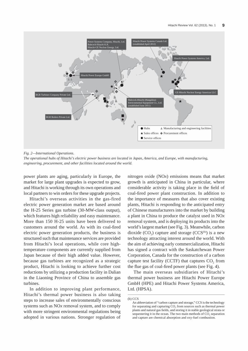
Global Activities of Hitachi’s Electric Power Business
Hiraku Ikeda
ONGOING GROWTH IN GLOBAL DEMAND FOR ELECTRIC POWERHITACHI is engaged in a variety of social infrastructure businesses, including those in the fields of thermal and nuclear power generation, electric power distribution, and renewable energy. These businesses operate primarily through Power Systems Company of Hitachi, Ltd. Global electric power generation is predicted to grow strongly, reaching about 1.7 times 2008 levels by 2030 (see Fig. 1). With extensive construction of new coal-fired thermal power plants planned for regions such as Eastern Europe and Asia, as well as the replacement of aging plants in Europe and the USA, demand is forecast to remain strong. Meanwhile, many nations, including the UK and the Republic of Lithuania, are continuing with plans for nuclear power plants, even after the Great East Japan Earthquake. Also, installation of renewable energy is accelerating around the world, and the market for electric power transmission and distribution is expected to expand, particularly in emerging economies.
Recognizing these market conditions, Hitachi’s strategy is to continue the active development of its overseas businesses.
ACCELERATING GLOBALIZATIONIn addition to supplying appropriate solutions to
their target markets, the aims of Hitachi’s various overseas electric power business operations include strengthening their marketing capabilities in all parts of the world, including nations such as India and
the Republic of South Africa, so that they can offer solutions that extend across all areas from electric power generation to distribution, and boosting their engineering capabilities and their ability to undertake overseas procurement and manufacturing (see Fig. 2). To increase the proportion of overseas sales (sales outside Japan), Hitachi is undertaking a reorganization of its procurement offices to improve cost-competitiveness, making active use of overseas production facilities, and encouraging local management of business activities. These policies are included in the Hitachi Smart Transformation Project(a). Other initiatives associated with overseas procurement include taking active steps to standardize equipment specifications and sharing vendor information to cut procurement costs.
THERMAL POWER BUSINESSThermal power accounts for approximately 60%
of global electricity demand, and consists primarily of power generated from coal or natural gas. Highly efficient, coal-fired electric power generation systems are among Hitachi’s key products, with approximately 30 units currently under construction. Three operational hubs located in Japan, the USA, and Europe, with another facility in India, drive the global activities of this business. As many coal-fired electric
40 (trillion kWh)
Renewable energy
Nuclear energy
Coal
Oil
Natural gas100%
119%
Approximately 1.7 times
167%
2008 2015 2030
30
20
10
0
Source: International Energy Outlook 2011
Fig. 1—Predicted Global Electric Power Generation (by Energy Source).Global electric power generation is predicted to grow strongly, reaching about 1.7 times 2008 levels by 2030.
(a) Hitachi Smart Transformation Project A project being undertaken by Hitachi to improve cost-competitiveness,
with the aim of achieving further growth in the global market. Formulated in FY2011, the project aims at cutting the total cost of sales in FY2015 by 5% relative to FY2010 by improving cost structures.
Hitachi Review Vol. 62 (2013), No. 1 9
power plants are aging, particularly in Europe, the market for large plant upgrades is expected to grow, and Hitachi is working through its own operations and local partners to win orders for these upgrade projects.
Hitachi’s overseas activities in the gas-fired electric power generation market are based around the H-25 Series gas turbine (30-MW-class output), which features high reliability and easy maintenance. More than 150 H-25 units have been delivered to customers around the world. As with its coal-fired electric power generation products, the business is structured such that maintenance services are provided from Hitachi’s local operations, while core high-temperature components are currently supplied from Japan because of their high added value. However, because gas turbines are recognized as a strategic product, Hitachi is looking to achieve further cost reductions by utilizing a production facility in Dalian in the Liaoning Province of China to assemble gas turbines.
In addition to improving plant performance, Hitachi’s thermal power business is also taking steps to increase sales of environmentally conscious systems such as NOx removal system, and to comply with more stringent environmental regulations being adopted in various nations. Stronger regulation of
nitrogen oxide (NOx) emissions means that market growth is anticipated in China in particular, where considerable activity is taking place in the field of coal-fired power plant construction. In addition to the importance of measures that also cover existing plants, Hitachi is responding to the anticipated entry of Chinese manufacturers into the market by building a plant in China to produce the catalyst used in NOx removal system, and is deploying its products into the world’s largest market (see Fig. 3). Meanwhile, carbon dioxide (CO2) capture and storage (CCS(b)) is a new technology attracting interest around the world. With the aim of achieving early commercialization, Hitachi has signed a contract with the Saskatchewan Power Corporation, Canada for the construction of a carbon capture test facility (CCTF) that captures CO2 from the flue gas of coal-fired power plants (see Fig. 4).
The main overseas subsidiaries of Hitachi’s thermal power business are Hitachi Power Europe GmbH (HPE) and Hitachi Power Systems America, Ltd. (HPSA).
(b) CCS An abbreviation of “carbon capture and storage,” CCS is the technology
for separating and capturing CO2 from sources such as thermal power plants and natural gas fields, and storing it in stable geological strata or sequestering it in the ocean. The two main methods of CO2 separation and capture are chemical absorption and oxy-fuel combustion.
Hitachi Power Systems Canada Ltd.(established April 2012)
Hitachi Power Systems America, Ltd.
Power Systems Company, Hitachi, Ltd.Babcock-Hitachi K.K.Hitachi-GE Nuclear Energy, Ltd.
Hitachi Power Europe GmbH
BGR Turbines Company Private Ltd.
BGR Boilers Private Ltd.
Babcock-Hitachi (Hangzhou) Environmental Equipment Co., Ltd.(established June 2011)
GE-Hitachi Nuclear Energy Americas LLC
Hubs
Sales offices
Service offices
Manufacturing and engineering facilities
Procurement offices
Fig. 2—International Operations.The operational hubs of Hitachi’s electric power business are located in Japan, America, and Europe, with manufacturing, engineering, procurement, and other facilities located around the world.

Global Activities of Hitachi’s Electric Power Business 10
NUCLEAR POWER BUSINESSNuclear power generation can be thought of as
an effective form of power generation for protecting the global environment, with benefits that include minimizing CO2 emissions. Overseas, the intention to proceed with plans for nuclear power exists in a number of nations, including Lithuania, the Socialist Republic of Viet Nam, India, the Republic of Poland, and the UK, and it is anticipated that demand for nuclear power plants will continue in the medium
to long term. Hitachi has established a “one team” collaboration with General Electric Company (GE) of the USA.
Hitachi and GE merged their nuclear power businesses in 2007, establishing Hitachi-GE Nuclear Energy, Ltd. and GE-Hitachi Nuclear Energy Americas LLC, which handles business outside Japan. Drawing on synergies between the two companies, these operations are able to supply high quality services that extend across research, design, fabrication, construction, and maintenance of light water reactors, fast-breeder reactors(c), and the nuclear fuel cycle.
Hitachi has recently been involved with the construction project for the Visaginas Nuclear Power Plant in Lithuania. Hitachi intends to continue its engagement with those nations that have an interest in nuclear power generation, and to supply nuclear power generation technology with high levels of safety and reliability.
The advanced boiling water reactor (ABWR(d)) developed in collaboration with Japanese power
Fig. 4—Signing of CCTF Contract.As part of a clean coal project being undertaken by the Saskatchewan Power Corporation, Canada, Hitachi and SaskPower will collaborate on the construction of a carbon capture test facility that captures CO2 from the flue gas of a coal-fired power plant, and also on experimental testing at the facility.
Fig. 3—Denitrification Catalyst Factory in Hangzhou, China.Rapid growth is anticipated in the Chinese market because nitrogen oxide (NOx) regulations are more stringent even than those in Japan, Europe, and the USA, and because a government subsidy program has been introduced.
(c) Fast-breeder reactor A type of nuclear reactor that uses mixed oxide fuel containing both
plutonium and uranium. While also generating electric power, a fast-breeder reactor produces more fuel than it consumes because some of the high-speed neutrons produced by the nuclear fission of plutonium transform uranium-238 into plutonium. The efficiency with which uranium material is consumed is dramatically higher than for a light water reactor
Hitachi Review Vol. 62 (2013), No. 1 11
companies that operate BWRs(e), GE, and Toshiba Corporation features simple construction and excellent economics, and it represents a form of electric power generation that is competitive with other energy sources because its low core output density means that output can easily be increased. The system provides easy ways for achieving higher burnup and has excellent fuel economics because of its ability to burn uranium fuel more efficiently than pressurized water reactors (PWRs). For these reasons, it is anticipated that the project in Lithuania will select a generation III + ABWR design as this is most up-to-date reactor design in actual operation, recognizing the reliability and operational experience that Hitachi-GE has built up with the ABWR.
GE-Hitachi is also taking a central role in developing the economic simplified boiling water reactor (ESBWR(f)).
Canada is the world’s largest producer of uranium, the fuel used in nuclear power plants. Hitachi-GE is also working with the Government of Saskatchewan (where all Canadian uranium production takes place)
on the joint research of small modular reactor designs and technology.
Nuclear power generation is an effective electric power generation technology for protecting the global
(d) ABWR An abbreviation of “advanced boiling water reactor.” ABWRs are
intended to provide improvements that include better safety, making the nuclear reactor containment vessel and building more compact, and reducing radiation dose during maintenance inspections by relocating the recirculation pumps to the bottom of the pressure vessel, instead of outside the nuclear reactor pressure vessel as on conventional BWRs. Through enhancements that include improvements to the control rod drive mechanism, use of a nuclear reactor containment vessel made of reinforced concrete, better emergency cooling for the core, the adoption of digital technology, and improvements to the human-machine interface, the ABWR is intended to improve on the safety, reliability, operational characteristics, controllability, and other features of the BWR. Other advantages include economics and less radioactive waste material.
(e) BWR An abbreviation of “boiling water reactor.” Reactors that use light water
(ordinary water) as a moderator and coolant can be broadly divided into BWRs and pressurized water reactors (PWRs). BWRs operate with the cooling water in a state of boiling so that the nuclear reactor pressure vessel acts as a steam generator. The resulting steam is supplied directly to a turbine to generate electric power. In contrast, the cooling water in a PWR is at high temperature and pressure, and this high pressure prevents it from boiling. This high-temperature, high-pressure water is supplied to a steam generator where a heat exchanger produces steam that is used to turn a turbine and generate electric power.
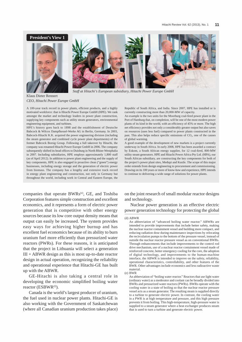
Klaus Dieter RennertCEO, Hitachi Power Europe GmbH
A 100-year track record in power plants, efficient products, and a highly motivated workforce: that is Hitachi Power Europe GmbH (HPE). We rank amongst the market and technology leaders in power plant construction, supplying key components such as utility steam generators, environmental engineering equipment, and turbines.HPE’s history goes back to 1898 and the establishment of Deutsche Babcock & Wilcox Dampfkessel-Werke AG in Berlin, Germany. In 2003, Babcock-Hitachi K.K. acquired the power engineering division (including the steam generator and combined cycle power plant departments) of the former Babcock Borsig Group. Following a full takeover by Hitachi, the company was renamed Hitachi Power Europe GmbH in 2006. The company subsequently shifted its head offices to Duisburg in North Rhine-Westphalia in 2007. Including subsidiaries, HPE employs approximately 1,800 staff (as of April 2012). In addition to power plant engineering and the supply of key components, HPE is also engaged in proactive clean (“green”) energy businesses, including energy storage and the generation of electric power from biomass. The company has a lengthy and extensive track record in energy plant engineering and construction, not only in Germany but throughout the world, including work in Central and Eastern Europe, the
Republic of South Africa, and India. Since 2007, HPE has installed or is currently constructing more than 20,000-MW of capacity.An example is the two units for the Moorburg coal-fired power plant in the Port of Hamburg that, on completion, will be one of the most modern power plants of its kind in the world, with an efficiency of 45% or more. The high net efficiency provides not only a considerably greater output but also saves on resources (uses less fuel) compared to power plants constructed in the past. This also helps reduce specific emissions of CO2, one of the causes of global warming.A good example of the development of new markets is a project currently underway in South Africa. In early 2008, HPE has been awarded a contract by Eskom, a South African energy supplier, for 12 coal-fired, 800-MW utility steam generators. HPE and Hitachi Power Africa Pty Ltd. (HPA), our South African subsidiary, are constructing the key components for both of the project’s power plant sites, Medupi and Kusile. The scope of this major order extends from design engineering to procurement and commissioning.Drawing on its 100 years or more of know-how and experience, HPE intends to continue to delivering a wide range of solutions for power plants.
President’s View 1
Staff at Hitachi’s European subsidiary, Hitachi Power Europe GmbH

Global Activities of Hitachi’s Electric Power Business 12
environment for reasons that include reducing CO2 emissions and being part of the best mix of energy sources, and it has also been treated as an important national policy in Japan. Hitachi-GE has continuous and deep experience in the construction of nuclear power plants in Japan, and intends to respond to demand from around the world in the future by drawing on the lessons from the accident at the Fukushima Daiichi Nuclear Power Station following the Great East Japan Earthquake to develop an ABWR with even higher levels of safety.
ELECTRIC POWER TRANSMISSION AND DISTRIBUTION BUSINESS
Together with advances in nuclear, thermal, and renewable power generation technology, improvements in electric power transmission and
distribution technology will be essential to achieving balanced progress in the field of electric power.
Developed economies currently have a requirement for the upgrading of aging transmission infrastructure, and there is also a need to build up the transmission infrastructure in emerging economies where growth in energy demand is strong. Meanwhile, progress is also being made on wide-area interconnections, including between multiple countries and across continents and oceans, applications that require ultra-high-voltage alternating current and direct current transmission of electric power. Grid stabilization systems for electric power transmission networks are required to cope with greater generation of renewable energy with fluctuating output, and rapid progress is being made on smart grids that use electric power efficiently. The Japanese government is currently considering a scheme in which electric power companies will need to separate electric power transmission and generation, and Hitachi is watching developments closely as it considers what specific measures it can take to make a contribution.
From its engineering offices, manufacturing facilities, and other operations throughout the world,
(f) ESBWR An abbreviation of “economic simplified boiling water reactor,” the
ESBWR is a BWR technology with improved safety and economics achieved through a simpler system design, including taking advantage of the boiling that occurs in the reactor (a characteristic of BWRs) to achieve natural circulation of water in the reactor, use of gravity-fed water from a pool above the reactor to cool the core during an emergency, and use of natural thermal radiation to minimize the pressure in the containment vessel.
Henry E. BartoliPresident and CEO, Hitachi Power Systems America, Ltd.
Hitachi Power Systems America, Ltd. (HPSA) is located in Basking Ridge, New Jersey and is responsible for sales and marketing, project execution, engineering/design, and procurement for all of Hitachi’s global energy products. This consists of advanced pulverized coal boilers, heat recovery steam generators, steam, gas and hydro turbines and generators, substation equipment, and air quality control systems for new plants and retrofit applications. As a single-point supplier, HPSA offers total solution services including operation and plant assessments, engineering studies, performance optimization, emissions improvement, equipment replacement and upgrades, and spare parts.HPSA’s mission is to provide state-of-the-art equipment and services that support the improvement of efficiency and reduce the environmental impact of new and existing facilities in the thermal, nuclear, and renewable markets.The landscape of the US generation market continues to change due to
uncertainty in regulation, limited demand growth, economic conditions, abundance of cheap gas, political outcomes, and so on. One area where HPSA has focused its efforts is on the development of air quality control technologies for pollution reduction. Due to stringent US regulations regarding emissions from power plants, HPSA has enhanced its portfolio of products for this market, including the recent signing of license agreements with Balcke-Dürr GmbH for fabric filter technology (in the fall of 2011) and with Solios Environment Inc. for dry scrubber technology (in March, 2012). With these two additional critical products, HPSA now offers comprehensive total pollution control systems to mitigate sulfur and nitrogen oxides as well as particulate matter, mercury, and other hazardous pollutants.Even with all the unknowns in the marketplace, HPSA’s goal is to position ourselves for future markets with technology, products and services that meet customers’ needs.
President’s View 2
New Jersey office of Hitachi Power Systems America, Ltd.
Hitachi Review Vol. 62 (2013), No. 1 13
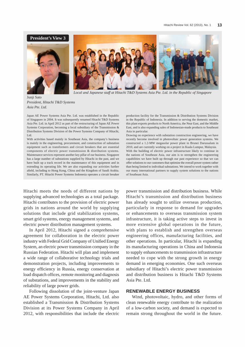
Hitachi meets the needs of different nations by supplying advanced technologies as a total package. Hitachi contributes to the provision of electric power grids in nations around the world by supplying solutions that include grid stabilization systems, smart grid systems, energy management systems, and electric power distribution management systems.
In April 2012, Hitachi signed a comprehensive agreement for collaboration in the electric power industry with Federal Grid Company of Unified Energy System, an electric power transmission company in the Russian Federation. Hitachi will plan and implement a wide range of collaborative technology trials and demonstration projects, including improvements to energy efficiency in Russia, energy conservation at load dispatch offices, remote monitoring and diagnosis of substations, and improvements in the stability and reliability of large power grids.
Following dissolution of the joint-venture Japan AE Power Systems Corporation, Hitachi, Ltd. also established a Transmission & Distribution Systems Division at its Power Systems Company in April 2012, with responsibilities that include the electric
power transmission and distribution business. While Hitachi’s transmission and distribution business has already sought to utilize overseas production, particularly in response to demand for upgrades or enhancements to overseas transmission system infrastructure, it is taking active steps to invest in more extensive global operations in the future, with plans to establish and strengthen overseas engineering offices, manufacturing facilities, and other operations. In particular, Hitachi is expanding its manufacturing operations in China and Indonesia to supply enhancements to transmission infrastructure needed to cope with the strong growth in energy demand in emerging economies. One such overseas subsidiary of Hitachi’s electric power transmission and distribution business is Hitachi T&D Systems Asia Pte. Ltd.
RENEWABLE ENERGY BUSINESSWind, photovoltaic, hydro, and other forms of
clean renewable energy contribute to the realization of a low-carbon society, and demand is expected to remain strong throughout the world in the future.
Junji SatoPresident, Hitachi T&D Systems Asia Pte. Ltd.
Japan AE Power Systems Asia Pte. Ltd. was established in the Republic of Singapore in 2004. It was subsequently renamed Hitachi T&D Systems Asia Pte. Ltd. in April 2012 as part of the restructuring of Japan AE Power Systems Corporation, becoming a local subsidiary of the Transmission & Distribution Systems Division of the Power Systems Company of Hitachi, Ltd.With activities based mainly in Southeast Asia, the company’s business is mainly in the engineering, procurement, and construction of substation equipment such as transformers and circuit breakers that are essential components of electric power transmission & distribution systems. Maintenance services represent another key pillar of our business. Singapore has a large number of substations supplied by Hitachi in the past, and we have built up a track record in the maintenance of this equipment and in extending its operating life. We are also expanding our activities further afield, including to Hong Kong, China and the Kingdom of Saudi Arabia. Similarly, PT. Hitachi Power Systems Indonesia operates a circuit breaker
production facility for the Transmission & Distribution Systems Division in the Republic of Indonesia. In addition to serving the domestic market, this plant exports products to North America, the Near East, and the Middle East, and is also expanding sales of Indonesian-made products to Southeast Asia in particular.Drawing on experience with substation construction engineering, we have recently become involved in photovoltaic power generation systems. We constructed a 1.2-MW megasolar power plant in Brunei Darussalam in 2010, and are currently working on a project in Kuala Lumpur, Malaysia.With the building of electric power infrastructure likely to continue in the nations of Southeast Asia, our aim is to strengthen the engineering capabilities we have built up through our past experience so that we can offer solutions to our customers that optimize the overall power system rather than being limited to individual substations. We intend to work together with our many international partners to supply system solutions to the nations of Southeast Asia.
President’s View 3
Local and Japanese staff at Hitachi T&D Systems Asia Pte. Ltd. in the Republic of Singapore
Global Activities of Hitachi’s Electric Power Business 14
Hitachi is focusing on increasing sales of renewable energy systems based on wind or photovoltaic power and on the development of systems in the smart grid field for stabilizing the output of renewable energy to the grid (using techniques such as storage battery systems for smoothing output fluctuations).
Hitachi supplies a downwind turbine system and has already received orders in Japan for more than 70 wind power generation systems (of which 15 are offshore installations). Hitachi, Ltd. acquired the wind power generation systems business of Fuji Heavy Industries Ltd. in 2012. In addition to receiving a boost from the feed-in tariff (FIT) scheme adopted in Japan, Hitachi has plans to become actively involved in the global market through the development of a floating offshore wind power generation system that has the potential to become a future global standard. In the field of photovoltaic power generation, Hitachi acts as a system integrator supplying total systems for megasolar power generation. The combined capacity of 1-MW or larger systems installed in Japan to date totals 16 MW. Hitachi’s total solutions for wind or photovoltaic power generation systems include techniques for smoothing fluctuations in output power using equipment such as power conditioners and storage batteries.
For its hydro power generation operations, Hitachi has established a joint-venture company with partners that include Mitsubishi Heavy Industries, Ltd. and Mitsubishi Electric Corporation. Demand in Japan is anticipated from upgrades, after-sales service, and
power uprating of existing power plants. Overseas, meanwhile, strong demand is anticipated from places such as China, Central and South America, and India that have extensive water resources. With overseas suppliers having a greater presence in the market, Hitachi is taking active steps toward overseas operations, including for its manufacturing facilities.
WORKING TOWARD GLOBALIZATION OF ELECTRIC POWER BUSINESS
Based around its operational hubs, Power Systems Company of Hitachi, Ltd. takes a global approach to engineering, manufacturing, and procurement across its entire electric power business. It is working toward the globalization of its electric power business through a “one team” collaborative organization in which Babcock-Hitachi K.K., Hitachi-GE Nuclear Energy, Ltd., and its other regional subsidiaries work together as part of the Hitachi Group.
Hiraku IkedaJoined Hitachi, Ltd. in 1980, and now works at the Strategy Planning Division, Strategic Management Division, Power Systems Company. He is currently engaged in the strategic planning, public relations, and government relations. Mr. Ikeda is a member of The Japan Society of Mechanical Engineers, the Gas Turbine Society of Japan, and the Thermal and Nuclear Power Engineering Society.
ABOUT THE AUTHOR

Hitachi Review Vol. 62 (2013), No. 1 15
Hitachi’s Gas Turbine Product Range and Development Background
Jinichiro Gotoh, Dr. Eng.
Shunichi Kuba, Dr. Eng.
Mitsuo Teranishi
Kenji Kamino
Fumiyuki Hirose
OVERVIEW: Since supplying its first gas turbine in 1966, total orders received by Hitachi to date have reached 600 units. The 1960s and 1970s were the formative years for Hitachi’s gas turbine business during which it expanded sales outside Japan, primarily through technical collaborations with General Electric Company, and built up the foundations of its current business. The 1980s and 1990s saw a boom in combined cycle plants that provided Hitachi with the opportunity to expand its domestic business, including being the first Japanese vendor to supply combined cycle systems with exhaust heat recovery. In 1988, Hitachi developed its H-25 gas turbine, the first model to use its own technology throughout for everything from design to manufacturing. Hitachi has also been marketing the H-25 internationally since 2000, and this has led to the development of its current global business. Hitachi’s gas turbine business can also be thought of as embodying the Pioneering Spirit that was part of what inspired the company’s original formation.
INTRODUCTIONALThOUGh its business has faced a number of difficulties over the years, including economic recessions and appreciation of the yen, total orders for hitachi’s gas turbines since its technical collaboration with General Electric Company (GE) have now reached 600, and they can be thought of as having solidified their role as a mainstay of thermal power generation. Those gas turbines have earned a strong reputation for reliability, with some of the early hitachi-GE units having been in operation for more than 30 years. hitachi built up the foundations of its current thermal power generation business in the subsequent period when combined cycle technology was becoming established in Japan, during which it led the market with its experience and with the environmental technologies needed to satisfy stringent Japanese regulations. it was during this time that hitachi developed the h-25 gas turbine using its own technology. The high performance and reliability of the h-25 have earned it a total of 151 installations. hitachi then went on to develop the h-15 sister product and the medium-capacity (100-MW class) h-80 gas turbine.
This article looks back at the more than 40 years of hitachi’s gas turbine business, and also describes developments over recent years.
HISTORYOrigins of Gas Turbine Manufacturing at Hitachi
hitachi’s involvement with gas turbines dates back to 1938 and a turbocharger for a 500-hP (1 hP = 0.7457 kW) exhaust turbine built as part of experimental research commissioned by the Japanese Naval Aeronautical Technology institution. The size of the exhaust turbine was progressively increased and a total of 800 units had been produced by the end of the second World War in August 1945. Work also proceeded on the testing and research of jet engines, with hitachi’s role including collaboration on the manufacture of the Ne-20 and the prototyping of the Ne-230. A prototype 1,100-kW open, two-shaft, regenerative gas turbine for power generation was completed in 1954. Although this prototype had been used to make a variety of research enhancements by 1959, it did not lead to commercial production as the market for gas turbines at that time had yet to develop.
Technical Partnership with GE(1) Manufacture of first gas turbine
in 1964, hitachi signed a joint manufacturing agreement with GE, the world’s leading gas turbine manufacturer. This led to the first hitachi-GE gas turbine being delivered to Nippon Petro Chemicals Co., Ltd. (as it was then known) in 1966. This Ms3002

Hitachi’s Gas Turbine Product Range and Development Background 16
two-shaft gas turbine had a rating of 6,000 kW and a turbine inlet temperature of 800°C.(2) Ms5001
The first Ms5001 was ordered from GE, completed in 1967, and delivered to American independent Oil Company (AMiNOiL). its output was 16,250 kW. it went on to be adopted around the world, becoming a mainstay of the hitachi product range with a total of 286 units delivered (see Fig. 1).(3) Mechanical-drive gas turbine
hitachi has supplied a total of 12 mechanical-drive gas turbines, consisting of eight Ms3002 models supplied via GE to what is now the Russian Federation in 1977, and the completion of the Ms5002 for customers who included société Nationale pour la Recherche, la Production, le Transport, la Transformation, et la Commercialisation des hydrocarbures s.p.a. (aka sonatrach), the Algerian national oil and gas company.(4) Large-capacity, high-performance gas turbines
in response to growing demand for large-capacity, high-performance gas turbines, the 60-hz Ms7001 was developed based on the Ms5001M, followed by the 50-hz Ms9001. The Ms9001B uses air cooling for the first stage buckets and nozzles, and hitachi received the first order for this model from the Kawasaki Thermal Power station of what is now the East Japan Railway Company, which was delivered in 1981. This plant was the first combined cycle power plant in Japan to use exhaust heat recovery.
The Ms7001E completed in 1981 included enhancements to the combustor and turbine cooling (air cooling of second stage buckets and nozzles also).
Combined cycle power plants burning liquefied natural gas (LNG) became a mainstream power source in the 1990s because of their high plant thermal efficiency and operating characteristics, and this drove demand for the gas turbines that are the major component of these plants. Three 1,100°C-class Ms7001EA gas turbines were supplied to the Yanai Power station of The Chugoku Electric Power Co., inc. in 1990, and three more in 1992. six Ms7001E gas turbines were supplied to the shin Oita Power station of Kyushu Electric Power Co., inc. in 1991. These were single-shaft combined cycle plants in which the gas turbine, generator, and steam turbine were linked by a single shaft (see Fig. 2).
Two 1,300°C-class Ms7001F gas turbines were supplied for single-shaft combined cycle plants at the Yanai Power station of Chugoku Electric Power in 1994, and two more in 1996.
it was at this time that interest was growing in the use of exhaust reheat combined cycle power plants that allowed short-turnaround repowering of existing steam-powered generation systems by adding a gas turbine. One 1,100°C-class Ms9001E unit was supplied to the Goi Thermal Power station of The Tokyo Electric Power Co., inc. in 1994. Another focus was on achieving higher efficiency at rated load, and a multi-shaft combined cycle power plant
Fig. 1—Cumulative Sales of Hitachi Gas Turbines.The total number of gas turbines supplied since 1966 has reached 600.
Cumulative output
Cumulativenumber of units
20,000
Cum
ulat
ive
outp
ut (
MW
)
No.
of
gas
turb
ines
that
hav
e co
mm
ence
d op
erat
ion
Fiscal year operation commenced
Model Output No.
MS1002 5,050 HP 2
MS3002 15,140 HP 28
H-15 16,900 kW 6
H-25 32,000 kW 151
MS5001 26,300 kW 286
MS5002 38,000 HP 12
MS6001B 39,160 kW 28
MS6001FA 70,140 kW 4
MS7001B/E/EA 85,400 kW 31
H-80 99,260 kW 12
MS7001F/FA 171,700 kW 30
MS9001B/E 123,400 kW 6
MS9001FA
* Output is under ISO conditions, fueled by gas.* Includes supplied gas turbines purchased from GE (as of October 2012).
255,600 kW 4
Total 600
18,000
16,000
14,000
12,000
10,000
8,000
6,000
4,000
2,000
0
1966
1968
1970
1972
1974
1976
1978
1980
1982
1984
1986
1988
1990
1992
1994
1996
1998
2000
2002
2004
2006
2008
2010
2012
0
100
200
300
400
500
600
700
isO: international Organization for standardization GE: General Electric Company

Hitachi Review Vol. 62 (2013), No. 1 17
comprising three Ms7001FAs and one steam turbine was supplied to the himeji No. 2 Power station of The Kansai Electric Power Co., inc. in 1996. in the same year, seven Ms7001FA gas turbines for single-shaft combined cycle power generation with high efficiency and excellent operating characteristics were also supplied to Kawagoe Thermal Power Plant of The Chubu Electric Power Co., inc. Three Ms7001FA gas turbines were supplied to the shin Oita Power station of Kyushu Electric Power in 1998. From the Ms7001EA supplied in 1990, these and all other subsequent LNG-fired units used dry low nitrogen oxide (NOx) combustors developed in-house by hitachi. The 1,300°C-class Ms6001FA was developed jointly with GE, with the first hitachi-made unit being supplied to the hitachi Rinkai Power station in 2000.
HISTORY OF GAS TURBINE DEVELOPMENT AT HITACHIDevelopment of H-25 Gas Turbine
As the thermal efficiency of the Ms5001 (output in the 25,000-kW class) was approximately 27%, hitachi recognized that a model with a more competitive level of thermal efficiency would be needed in the future and therefore set about developing its own highly efficient gas turbine with a similar output. Through separate development of a high-performance compressor, turbine, and combustor, hitachi developed a high-performance 25,000-kW-class gas turbine (the h-25) with a combustor exit temperature of 1,260°C in 1988. The compressor was an axial compressor with a pressure ratio of 15 that had been scaled up from
a model used for experimental testing. The first unit was supplied for use in a cogeneration power plant fueled by LPG and A-type fuel oil at the Tokuyama Refinery of idemitsu Kosan Co., Ltd. The combustor was a standard model with a diffusion burner and steam injection (see Fig. 3 and Fig. 4).
H-25 Gas Turbine Technology(1) Compressor
improving the efficiency of gas turbines requires a high pressure ratio and high efficiency performance from the compressor. The challenges of compressor development include finding ways to prevent instabilities such as rotating stall and surging. it is also necessary to ensure that the compressor has the reliability to ensure stable operation over a wide range of flow rates from startup to shutdown. hitachi
Fig. 3—H-25 Gas Turbine.The photograph shows an overview of an H-25 gas turbine with the upper casing removed.
Air intake plenum 17-stage axial
air compressor
Multi-can combustor (10 cans)
Impact-type three-stage turbine
Exhaust diffuser
Rear supportFront support
Coupling
Turbine base
Fig. 4—Cross Section of H-25 Gas Turbine.H-25 was the first gas turbine that was entirely developed by Hitachi. A scaled down version, the H-15, was developed three years later.
Fig. 2—Overview of Yanai Power Station of The Chugoku Electric Power Co., Inc.The site consists of two 700-MW combined cycle power plants. Unit 2 is an ACC plant and was Japan’s first 1,300°C-class gas turbine. Unit 2-1 commenced commercial operation in March 1994, and Unit 2-2 commenced commercial operation in January 1996.
ACC: advanced combined cycle power plant (a combined cycle power plant incorporating a high-performance gas turbine with a combustion temperature of 1,300°C)

Hitachi’s Gas Turbine Product Range and Development Background 18
embarked on its own development to establish design techniques that can achieve both performance and reliability in multi-stage axial compressors, and in 1983 achieved the performance targets it had set for a prototype 17-stage compressor with a pressure ratio of 15. These were advanced specifications for that time. hitachi was also able to determine the characteristics of the rotating stall phenomenon based on actual measurements made on the prototype and incorporate them into its multi-stage compressor design techniques.
The axial compressor for the h-25 gas turbine was developed based on a similar design to this prototype compressor. in response to demand for further efficiency improvements, hitachi subsequently embarked on the development of an axial compressor (with a mean stage pressure ratio of 1.19) with the aim of achieving a world-leading pressure ratio. hitachi also built a prototype scale model including all stages in 1999 with the aim of verifying the robust reliability and aerodynamic performance of this compressor. The prototype achieved close to target performance during testing and allowed hitachi to establish design techniques for high pressure ratios and higher loads. in addition to transonic stage design techniques, the development also sought to improve performance by utilizing multi-stage flow analysis to match the cascade of blades in the compressor (see Fig. 5).(2) Turbine
The turbine in the h-25 gas turbine has a three-stage configuration. Fig. 6 shows the cooling configuration for the first stage. The first stage nozzles achieved high cooling efficiency using a combination of impingement cooling and film cooling with
pin fin cooling on the trailing edges. The cooling mechanism for the first stage buckets used return flow cooling, which was a new technique at the time of development. The design includes a turbulence promoter on the surface in the cooling flow path to improve performance without using a large volume of cooling air.
0.0
1.5
Fig. 5—Example Multi-stage Flow Analysis of Axial Compressor for Gas Turbine.Higher compressor pressures and loads are essential to making gas turbines more efficient.
Cooling air
Pin fin cooling
Impingement cooling
Film cooling
Front sideflow path
Rear side flow path
Cooling air
First stage nozzles First stage buckets
Fig. 6—Turbine Blade Cooling Mechanism for H-25 Gas Turbine.The first stage nozzles use a combination of impingement cooling and film cooling, with pin fin cooling on the trailing edges. The cooling mechanism for the first stage buckets used return flow cooling, which was a new technique at the time of development.
Flow sleeve
To turbine
Compressor discharge
Combustion liner
Transition piece
Diffusion combustion(F1) nozzle
Pre-mixerPre-mixed combustion
(F2) nozzle
Fig. 7—LNG-fired, Low-NOx Combustor and Dual-fuel, Low-NOx Combustor.The combustor for the H-25 gas turbine, shown here, achieved a level of NOx emissions (25 ppm or less) that was among the best in its class at the time.

Hitachi Review Vol. 62 (2013), No. 1 19
units to countries around the world. The h-25 and h-15 gas turbines now have a strong reputation for high performance and reliability, with totals sales exceeding 150 units. similarly, total operating time has exceeded 1.4 million hours, operating reliably throughout the world (see Fig. 8).
H-25 Gas Turbine ApplicationsA feature of the h-25 gas turbine is its wide range
of applications, which extend from power companies to petrochemical companies.
One recent example of the supply of a gas turbine to a power company was the Nyíregyházi Kombinált Ciklusú Erőmű (NYKCE) Project of E.ON hungária in hungary that commenced operation in 2007 (see Fig. 9). The NYKCE Project is a multi-shaft combined cycle plant consisting of one h-25 gas turbine, one
(3) CombustorFig. 7 shows the structure of the LNG-fired, low-
NOx combustor in the h-25 gas turbine. A downsized version of the third-generation combustor used in the 1,300°C-class gas turbine was designed, consolidating the experience and technology built up on the large models. This pre-mixed, low-NOx combustor with a diffusion pilot is based on a ring-shaped flame holder and achieves class-leading levels of NOx emissions (25 ppm or less). To allow a wider range of fuels, hitachi has developed a dual-fuel gas/oil, low-NOx combustor that can burn oil and also achieve gas-fueled performance equivalent to a dedicated gas combustor. The combustor maintains a stable pre-mixed flame when fueled by gas, and has a radial type flame holder to promote mixing of oil and air when fueled by oil, ensuring stable combustion when fueled by gas or oil alone, a mixture of the two, or when switching between fuels.
EXPANSION OF GAS TURBINE BUSINESSExpansion of Overseas Business
For about ten years after the first h-25 gas turbine was delivered in 1988, most installations were used for cogeneration at petrochemical companies in Japan. Gas turbine users typically place a high priority on a product’s track record, and they can be reluctant to select new models. in particular, GE’s Ms5001 was the top selling gas turbine in the same class and had a large presence in the market. Accordingly, hitachi embarked on a program to expand sales that combined marketing, technology, and design. Based on roughly a decade of experience from Japan, the first h-25 gas turbine supplied to a customer outside Japan was delivered to south Korea in 2000, and hitachi subsequently went on to deliver a large number of
Fig. 8—History of Gas Turbine Development by Hitachi.The graph shows deliveries of H-25 gas turbines in Japan and overseas up until May 2012. H-25 gas turbines are operating reliably in a wide range of environments, from the Russian Federation where temperatures fall as low as -48°C to the Republic of Iraq where temperatures reach up to 50°C.
Japan150 50
40
30
20
1988
1989
1990
1991
1992
1993
1994
1995
1996
1997
1998
1999
2000
2001
2002
2003
2004
2005
2006
2007
2008
2009
2010
2011
2012
10
0
First export gas turbinecommences operation.
Year of commencing operation
Overseas marketingcommences.
Cumulative number of units
Num
ber
of g
as tu
rbin
es e
nter
ing
oper
atio
n du
ring
yea
r
Cum
ulat
ive
num
ber
of u
nits 120
90
60
30
0
Overseas
Fig. 9—NYKCE Project of E.ON Hungária in Hungary.This power plant was constructed to supply power to nearby factories through a grid interconnection while also supplying heat for space heating.

Hitachi’s Gas Turbine Product Range and Development Background 20
h-25 gas turbines are also used at the world’s leading LNG facilities. A total of 12 units have been supplied to the Damietta Project in the Arab Republic of Egypt, the sakhalin-2 Project in Russia, and the Bonny Project in the Federal Republic of Nigeria. The h-25 has a strong reputation for stable performance and reliability in the oil and gas industry (including oil refineries and fertilizer plants), and accounts for half of all orders.
The sakhalin-2 Project in Russia is a cold-climate application where outdoor temperatures fall as low as -48°C, and the four h-25 gas turbines are installed indoors together with the waste heat recovery units (see Fig. 11). To improve plant operation, two of the four units are solely gas-fired, with dry low-NOx combustors, while the other two use dual-fuel (gas and oil) dry low-NOx combustors.
in the Middle East, hitachi has received orders for h-25 gas turbines fueled by natural gas and light oil for the Republic of iraq from Japan international Cooperation system as part of its aid program after the iraq War (see Fig. 12). Three gas turbines were supplied to the Taji Gas Turbine Power station in 2007, and two gas turbines were supplied to the Mosul Gas Turbine Power station in 2008. As supervisory staff from Japan were not able to be sent to the iraqi site for installation and commissioning due to security considerations, hitachi decided to handle gas turbine installation and commissioning remotely. While on-
waste heat recovery unit with supplementary burners, and one steam turbine. The net combined cycle output is between 29.5 and 49.5 MW. The plant operates as a cogeneration system that uses the waste heat of the gas turbine to supply hot water for district heating, and also high-pressure (26 bar, where 1 bar = 0.1 MPa) and low-pressure (7.5 bar) steam to nearby factories. As a highly efficient plant, it achieves a cogeneration efficiency of 89.3%. in terms of its environmental performance, it features a low-NOx combustor with emissions of 25 ppm (dry) [15% oxygen (O2) equivalent] or less under rated operating conditions.
An example application at a petrochemical company is the Betara gas field development project of PetroChina Co., Ltd. (see Fig. 10). Located on the island of sumatra in the Republic of indonesia, a long way from the electric power grid, the project uses three h-25 gas turbines to supply power with an island operation configuration. The site includes a large number of compressors driven by electric motors in the megawatt range. While compressors like these have conventionally been driven mechanically by a gas turbine in the past, the site recognized the benefits of centralizing power generation using h-25 gas turbines, which include flexibility of operation and layout, less maintenance, less spare parts, and cost savings. switching all compressors to electric motor drive also improved the ease-of-operation of the overall system.
Fig. 10—Betara Project of PetroChina Co., Ltd. in Republic of Indonesia.The plant receives gas and liquids by pipeline from several dozen nearby gas wells and performs gas-liquid separation to produce natural gas. Exhaust heat from the H-25 gas turbines is used for the high-temperature gas needed to regenerate the adsorbent (molecular sieve) used to remove the water content from the process gas.
Fig. 11—Sakhalin-2 Project in Russian Federation.This is an example of the H-25 gas turbine being deployed in a cold-climate application.
WHRU
Exhaust silencer duct
Gas turbine building
Air intakehouse
H-25 gas turbine compartmentGenerator
(H-25 gas turbine + WHRU) × 4
WhRU: waste heat recovery unit

Hitachi Review Vol. 62 (2013), No. 1 21
generation system that commenced operation in 1991. As its efficiency was low compared to the latest power generation systems, it was mainly used for peak load. A proposal to replace the gas turbine was formulated with the aims of increasing efficiency and flexibility. This increased the plant efficiency by 3% (absolute) and also helped reduce CO2 emissions. As the project involved improving efficiency by only replacing the gas turbine, in accordance with the customer’s requirements, it had to be installed around the existing equipment and leave the shaft end output unchanged. Accordingly, a two-shaft configuration was adopted with different speeds for the compressor driveshaft (4,580 rpm) and output shaft (3,600 rpm). The h-80 is a heavy-duty gas turbine with the largest capacity of any two-shaft model in the world*.
AHAThitachi is currently developing the advanced humid
air turbine (AhAT), a highly efficient system with excellent operational characteristics. The AhAT is a new type of gas turbine system with an enhanced regeneration cycle that is capable of higher efficiency without increasing the pressure ratio or combustion temperature. Also, because it does not use a boiler or steam turbine, the AhAT should be capable of a rapid load changes and flexible operation. hitachi has already confirmed the viability of the system by conducting testing on a pilot plant with an output in the 3-MW class (see Fig. 14). Meanwhile, experimental trials on a 40-MW-class demonstration system for developing specific technologies required for commercialization commenced in the end of 2011.
site work did not always go smoothly, the eagerness of the iraqi personnel involved in the project to construct the plant for themselves and the desire on the side of the hitachi engineers to help with the iraqi recovery combined to bring the plant successfully into operation.
DEVELOPMENTS OVER RECENT YEARSDevelopment of H-80 Gas Turbine
hitachi developed the h-80 gas turbine based on technology built up with the h-25. The first unit was supplied to the shin Oita Power station of Kyushu Electric Power in 2010 (see Fig. 13). Unit 1 at the shin Oita Power station was a combined cycle power
Fig. 13—H-80 Gas Turbine Supplied to Shin Oita Power Station of Kyushu Electric Power Co., Inc.This is one of the world’s largest two-shaft gas turbines. It is helping boost the efficiency of aging gas turbines.
Filter house
Generator
Cooling tower
Waste watertreatment unit
Load resistor
Length: 26 m
GT enclosure
Height: 11.5 m
AHAT pilot plant facility (Hitachinaka City, Ibaraki Prefecture, Japan)
Humidifyingtower
Waterrecovery
unit
Regenerator exchanger
Water supply humidifier
Exhaust stack
Fig. 14—3-MW-class AHAT System Pilot Plant.Hitachi has confirmed the viability of the AHAT system.
AhAT: advanced humid air turbine
* As of October 2012, based on hitachi, Ltd. research.
Fig. 12—Recovery Aid Project for the Republic of Iraq.With supervisory staff from Hitachi unable to be sent to the site, Iraqi personnel undertook all work from installation to commissioning by themselves.

Hitachi’s Gas Turbine Product Range and Development Background 22
Shunichi Kuba, Dr. Eng.Joined Hitachi Engineering Co., Ltd. in 1979, and now works at the Gas Turbine Design Department, Hitachi Works, Power Systems Company, Hitachi, Ltd. He is currently engaged in gas turbine system design and promotion. Dr. Kuba is a member of the GTSJ.
Kenji KaminoJoined Hitachi, Ltd. in 1980, and now works at the Americas Department, International Sales & Marketing Division, Power Systems Company. He is currently engaged in the international sales & marketing of gas turbines.
Jinichiro Gotoh, Dr. Eng.Joined Hitachi, Ltd. in 2000, and now works at the Global Strategy Planning Department, Thermal Power Global Business Development Division, Thermal Power Systems Division, Power Systems Company. He is currently engaged in global strategy planning for thermal power plant business. Dr. Gotoh is a member of The Japan Society of Mechanical Engineers, The Society of Materials Science, Japan, and the Gas Turbine Society of Japan (GTSJ).
Mitsuo TeranishiJoined Hitachi, Ltd. in 1979, and now works at the Thermal Power Service Business Division, Thermal Power Systems Division, Power Systems Company. He is currently engaged in overseas gas turbine after-service business. Mr. Teranishi is a member of the GTSJ.
Fumiyuki HiroseJoined Hitachi, Ltd. in 1973, and now works at the Thermal Power Service Business Division, Thermal Power Systems Division, Power Systems Company. He is currently engaged in thermal power systems service business.
ABOUT THE AUTHORS
hitachi aims to produce commercial models in the future in the medium-capacity class.
CONCLUSIONSThis article has looked back at the more than
40 years of hitachi’s gas turbine business, and also described developments over recent years.
The history of hitachi’s gas turbine business can be seen as a reflection of the ongoing Pioneering spirit that dates back to the company’s founding. in the future, hitachi intends to continue taking up the challenge of greater innovation with the aim of becoming a leading manufacturer of medium-capacity gas turbines.

Hitachi Review Vol. 62 (2013), No. 1 23
Titanium 50‑inch and 60‑inch Last‑stage Blades for Steam Turbines
Shigeki Senoo, Ph.D., PE.jp
Kunio Asai
Atsuhiro Kurosawa
Goingwon Lee
OVERVIEW: Hitachi has developed 3,600 r/min 50‑inch blades and 3,000 r/min 60‑inch blades as last‑stage buckets for steam turbines with some of the largest annulus areas in the world. Adopting these blades for use in a 1,000‑MW class steam turbine provides benefits that include improving turbine efficiency in relative terms by approximately 2.5% over that of steam turbines using 40/48‑inch last‑stage buckets, and increasing reheat steam temperature from 600°C to 620°C. In response to the problem of supersonic inflow at the tips of the buckets, supersonic turbine blades were developed to reduce loss, and the fluid performance of these blades was verified through cascade tunnel testing. In addition, a titanium alloy with a high specific strength was used to keep the centrifugal stresses in both blade and rotor within allowable limits. The 50‑inch blades that were developed will be used in the 1,050‑MW ultra‑supercritical pressure steam turbines in units No. 9 and No. 10 at Korea Western Power Co., Ltd.’s Tae‑An Thermal power plant.
INTRODUCTIONSTEAM turbines are used in various types of power generation including coal-fired power generation, gas turbine combined-cycle power generation, nuclear power generation, and other power generation systems. Together, they provide the world with more than 60% of its electric power. The world’s demand for electric power will continue increasing as the population grows and standards of living improve in developing economies, with demand predicted to reach approximately 1.5 times that of 2009 in the year 2030, and approximately 2.1 in the year 2050(1). As a result, along with the expanded use of renewable energy, there is also a demand for increases in the amount of electric power generated by steam turbines. In particular, coal-fired power generation is important because coal reserves are plentiful and there is not much imbalance in amounts from region to region, so coal-fired power generation can be effectively utilized.
On the other hand, from the perspective of environmental compliance, it is necessary to improve the efficiency of steam turbines in order to reduce carbon dioxide (CO2) emissions. The average gross thermal efficiency of the world’s coal-fired power plants is approximately 33% (lower heating value standard, 2009), and by replacing the turbines in these plants with Hitachi’s new ultra-supercritical pressure*1
steam turbines with efficiency greater than 45%, it will be possible to reduce CO2 emissions by more than 30%.
Fig. 1—3,600 r/min 50‑inch Last‑stage Buckets.With an annulus area among the largest in the world*2, turbine efficiency is improved by reducing wasted kinetic energy.
*1 Steam conditions with temperature at 593°C or higher and pressure at 24.1 MPa or higher.
*2 Based on research into publically available information as conducted by Hitachi, Ltd. Current as of September 2012.
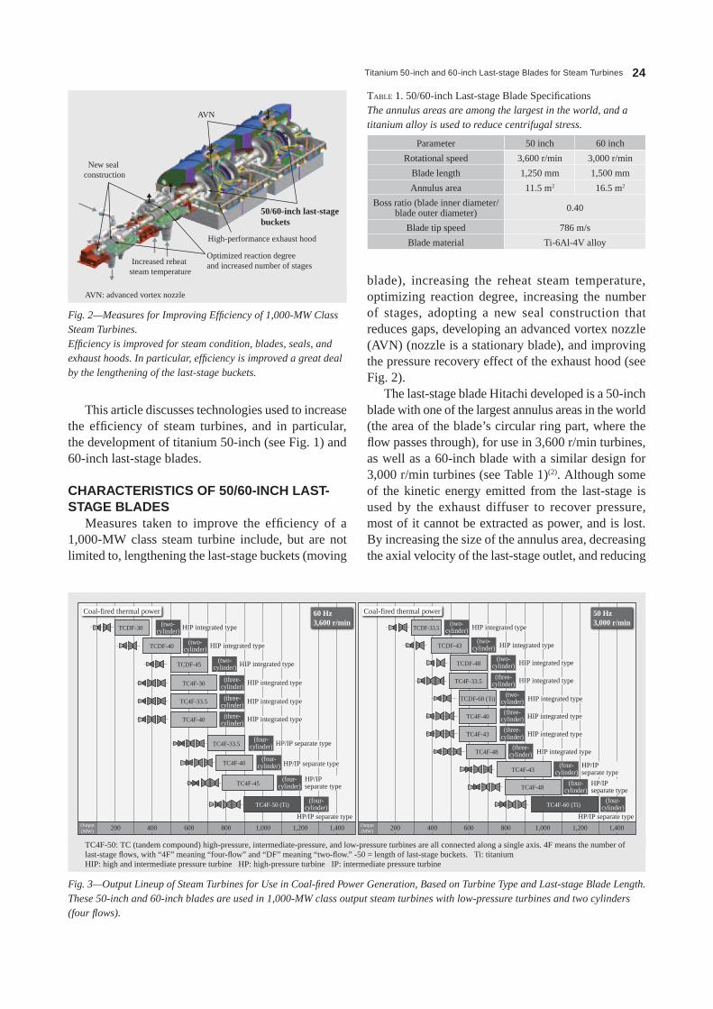
Titanium 50-inch and 60-inch Last-stage Blades for Steam Turbines 24
This article discusses technologies used to increase the efficiency of steam turbines, and in particular, the development of titanium 50-inch (see Fig. 1) and 60-inch last-stage blades.
CHARACTERISTICS OF 50/60‑INCH LAST‑STAGE BLADES
Measures taken to improve the efficiency of a 1,000-MW class steam turbine include, but are not limited to, lengthening the last-stage buckets (moving
blade), increasing the reheat steam temperature, optimizing reaction degree, increasing the number of stages, adopting a new seal construction that reduces gaps, developing an advanced vortex nozzle (AVN) (nozzle is a stationary blade), and improving the pressure recovery effect of the exhaust hood (see Fig. 2).
The last-stage blade hitachi developed is a 50-inch blade with one of the largest annulus areas in the world (the area of the blade’s circular ring part, where the flow passes through), for use in 3,600 r/min turbines, as well as a 60-inch blade with a similar design for 3,000 r/min turbines (see Table 1)(2). Although some of the kinetic energy emitted from the last-stage is used by the exhaust diffuser to recover pressure, most of it cannot be extracted as power, and is lost. By increasing the size of the annulus area, decreasing the axial velocity of the last-stage outlet, and reducing
Coal-fired thermal power Coal-fired thermal power
TCDF-30 HIP integrated type(two-cylinder) TCDF-33.5 HIP integrated type(two-
cylinder)
HIP integrated type(two-cylinder)
HIP integrated type(two-cylinder)
HIP integrated type(three-cylinder)
HIP integrated type(three-cylinder)
HIP integrated type(three-cylinder)
HP/IP separate type(four-cylinder)
HP/IP separate typeHP/IP separate type
(four-cylinder)
HP/IP separate type(four-
cylinder)
HP/IP separate type
(four-cylinder)
(four-cylinder)
60 Hz3,600 r/min
50 Hz3,000 r/min
TCDF-40 HIP integrated type(two-
cylinder)TCDF-43
TCDF-45 HIP integrated type(two-cylinder)TCDF-48
HIP integrated type(three-
cylinder)TC4F-40
HIP integrated type(three-
cylinder)TC4F-43
HIP integrated type(three-
cylinder)TC4F-48
HP/IP separate type
(four-cylinder)TC4F-43
HP/IP separate type
(four-cylinder)TC4F-48
TC4F-30 HIP integrated type(three-cylinder)TC4F-33.5
HIP integrated type(two-
cylinder)TCDF-60 (Ti)
TC4F-40
TC4F-33.5
TC4F-40
TC4F-45
TC4F-50 (Ti)
1,4001,2001,0008006004002001,4001,2001,000800600400200Output(MW)
Output(MW)
TC4F-60 (Ti)
TC4F-33.5
Fig. 3—Output Lineup of Steam Turbines for Use in Coal-fired Power Generation, Based on Turbine Type and Last-stage Blade Length.These 50-inch and 60-inch blades are used in 1,000-MW class output steam turbines with low-pressure turbines and two cylinders (four flows).
TC4F-50: TC (tandem compound) high-pressure, intermediate-pressure, and low-pressure turbines are all connected along a single axis. 4F means the number of last-stage flows, with “4F” meaning “four-flow” and “DF” meaning “two-flow.” -50 = length of last-stage buckets. Ti: titaniumhiP: high and intermediate pressure turbine hP: high-pressure turbine iP: intermediate pressure turbine
Parameter 50 inch 60 inch
Rotational speed 3,600 r/min 3,000 r/min
Blade length 1,250 mm 1,500 mm
Annulus area 11.5 m2 16.5 m2
Boss ratio (blade inner diameter/blade outer diameter) 0.40
Blade tip speed 786 m/s
Blade material Ti-6Al-4V alloy
TABLE 1. 50/60-inch Last-stage Blade specificationsThe annulus areas are among the largest in the world, and a titanium alloy is used to reduce centrifugal stress.
Fig. 2—Measures for Improving Efficiency of 1,000-MW Class Steam Turbines.Efficiency is improved for steam condition, blades, seals, and exhaust hoods. In particular, efficiency is improved a great deal by the lengthening of the last-stage buckets.
AVN
New seal construction
50/60-inch last-stage buckets
High-performance exhaust hood
Optimized reaction degree and increased number of stagesIncreased reheat
steam temperature
AVN: advanced vortex nozzle

Hitachi Review Vol. 62 (2013), No. 1 25
the emitted kinetic energy, it is possible to improve efficiency. The developed blades have annulus areas approximately 1.4 times as large as the annulus areas of previous 40-inch and 48-inch blades, and this greatly contributes to the improved efficiency.
The 50-inch and 60-inch blades that were developed are used in 3,600 r/min and 3,000 r/min 1,000-MW class steam turbines, respectively. Low-pressure turbines are two-cylinder/four-flow designs, with a four-cylinder construction shared by high-pressure and intermediate-pressure turbines (see Fig. 2). This completes a wide lineup of steam turbines for coal-fired power generation, ranging from 200 to 1,300-MW (see Fig. 3).
When the aforementioned efficiency improvement measures are taken and the reheat steam temperature is increased to 620°C in a 1,000-MW class steam turbine using the developed last-stage buckets, turbine efficiency can be improved approximately 2.5% relative to a steam turbine with a reheat steam temperature of 600°C using 40/48-inch last-stage buckets.
FLUID PERFORMANCE DESIGNThe reduction of loss in supersonic inflow is an
aerodynamic issue affecting the development of 50-inch and 60-inch-long blades. As blades grow longer, the circumferential velocity increases in the tips of the buckets, causing the relative inflow speed to go supersonic. supersonic inflow causes shockwaves upstream in the buckets, which in turn interfere with the boundary layer at the blade surface, possibly resulting in loss.
The inflow Mach number was reduced, and a supersonic turbine blade was developed in order to reduce loss caused by supersonic inflow (see Fig. 4).
Reduction in Inflow Mach Numberin order to reduce the inflow Mach number,
lowering the reaction degree (bucket load/stage load) was considered first. With a lower reaction degree, the nozzle outlet pressure is reduced as the nozzle outflow speed is increased, resulting in a lower relative inflow speed for the buckets.
At the nozzle outlet, however, this balances out with the centrifugal force caused by the swirl flow with its convex curvature, causing the pressure to increase as it moves closer to the outer circumference (see Fig. 5). Therefore, to decrease the nozzle outlet pressure at the outer circumference, it is necessary to reduce the pressure gradient in the radial direction.
For this reason, it is decided to develop technology that would control streamline curvature on the meridional plane, or in other words, on the plane including the turbine’s axis of rotation (see Fig. 6). specifically, by inducing a meridional streamline at the nozzle outlet with a concave curvature that is reversed from the convex curvature of the swirl flow, the pressure on the outer circumference side was decreased while the pressure on the inner circumference side was increased (see Fig. 5). The concave meridional streamline was introduced using the concave meridional inner wall (see Fig. 6) and the advanced vortex nozzle (see Fig. 7).
The advanced vortex nozzle is a nozzle tilted in the circumferential direction with the blade’s
Fig. 4—Measures to Reduce Loss Caused by Supersonic Inflow on Bucket Tips.Shockwave loss was reduced by lowering the inflow Mach number and developing a supersonic turbine blade.
(1) Lower inflow Mach number
(2) Development of supersonic turbine blade
(a) Lower degree of reaction
(b) Meridional streamline curvature control
• Advanced vortex nozzle
• Concave meridional inner wall shape
Fig. 5—Relationship between Meridional Streamline and Radial Direction Pressure Gradient.By introducing a meridional streamline curvature with a concave shape to the nozzle outlet, a negative pressure gradient is induced in the radial direction, increasing the pressure in the inner circumference of the nozzle outlet while reducing the nozzle outflow Mach number.
High
High
Low
Low Meridional streamline
Axial direction
Swirl flow
Nozzle
Circum
feren
tial
direc
tion
Pres
sure
Pres
sure
Radial direction

Titanium 50-inch and 60-inch Last-stage Blades for Steam Turbines 26
pressure surface facing the inner circumference. Although with a straight stacking nozzle, a vortex is only generated around an axis in the radial direction, with an advanced vortex nozzle, it is curved in the circumferential direction, and also induces a vortex in the meridional plane perpendicular to the circumferential direction (see Fig. 7). As shown in Fig. 6, this meridional vortex forms a meridional streamline with a concave curvature between the nozzle and the buckets. The concave meridional inner wall introduces a concave curvature to the streamline near the inner circumference.
The advanced vortex nozzle and meridional inner wall shape were optimally designed using three-dimensional stage turbulent flow analysis. The Mach number distribution resulting from this analysis is shown in Fig. 6. The relative Mach number of the buckets tip’s inflow is reduced to 1.26, which is low enough that a strong upstream shockwave is not generated. Also, when the reaction of the entire stage is reduced, although the outflow Mach number on the nozzle’s inner circumference side exceeds 1.6, meridional streamline curvature control technology makes it possible to only decrease the pressure on the outer circumference side while increasing the pressure on the inner circumference side, so the outflow Mach number on the inner circumference side can be lowered to approximately 1.4.
Development of Supersonic Turbine Blades A supersonic turbine blade was developed that can
inhibit shockwave loss(3). With these newly developed long steam turbine blades, the supersonic inflow is accelerated between blades and outflows at an even higher supersonic speed, which is something not even the latest jet engines can do. For this reason, hitachi used a numerical turbulence analysis method(4) that it developed to optimize the shape of the supersonic turbine blade while considering the characteristics of the flow passage area and the long steam turbine blades, and verified fluid performance with supersonic cascade tunnel testing(2).
These blades offer the following three major characteristics:(1) The flow path between blades is the expanding flow path with a minimal flow path area part (throat) at the inlet.(2) The blade thickness increases gradually at the leading edge.(3) Curvature is low on the upstream side of the blade pressure surface.
Characteristic (1) causes the supersonic flow’s accelerated expansion to be smooth between the blade’s flow paths and weakens the trailing edge shockwave, while characteristics (2) and (3) weaken the upstream shockwave and equalize the flow at the inlet throat, which makes it possible to satisfy the mass flow rate design specifications.
Fig. 7—Comparison between Advanced Vortex Nozzle and Straight Stacking Nozzle.The advanced vortex nozzle is a nozzle with the blade’s pressure surface slanted in the circumferential direction towards the inner circumference. This curve induces a vortex on the meridional plane, controlling the meridional streamline and adjusting the Mach number.
Vortex lines
Radialvortex
Meridionalvortex
Radialvortex
Circumferential direction
Suction surface
Suction surfaceSuction surface
AVN Straight stacking nozzle
Pressure surface
Pressure surface
Radial direction
Circumferential directionCircumferential direction
Radial direction
Fig. 6—Mach Number Distribution in Meridional Plane through Three-dimensional Stage Turbulent Flow Analysis.The nozzle part is the Mach number, and the bucket part is the relative Mach number. The vortex induced by the advanced vortex nozzle and the concave inner wall shape induce a meridional streamline with a concave curvature at the nozzle outlet, keeping the relative Mach number low for the nozzle outflow and the bucket inflow.
Nozzle induced meridional vortex
Meridional streamline
Mach number
2.01.91.81.71.61.41.31.21.11.00.90.80.70.60.40.30.20.10.0
Meridional inner wall
NozzleBucket
1.26
1.4

Hitachi Review Vol. 62 (2013), No. 1 27
During the cascade test, the tested section was affixed to the Kyushu University supersonic wind tunnel (see Fig. 8). This is an intermittent wind tunnel, and air was used as the working fluid. A convergent-divergent nozzle was used to set the Mach number of the inlet’s supersonic flow, and the angle of the upper tailboard was changed to adjust the pressure ratio. suction from the downward sidewall to the sidewall boundary layer improved the periodicity of the cascade flow. The seven test blades were 1/5th the scale of production blades, the aspect ratio was 1.07, and flow two-dimensionality was secured. The Reynolds number based on the blade’s chord length was the same 2.3 × 10⁶ as for production blades.
These cascade tunnel tests successfully verified that the newly developed supersonic turbine blades satisfy the design conditions and are high-performance. A schlieren photograph used in measurement during the testing is shown in Fig. 9. These are test results with an inflow Mach number of 1.26 and an isentropic outflow Mach number of 2.1. since the effects of the reflected shockwave on the sidewall are small, the flow between the 2nd and 4th blades from upstream was noted. The black shadow around the blades is strain from the construction of the acrylic sidewall channel. Regardless of the supersonic inflow, no strong shockwave is generated, which indicates the boundary layer of the blade surface does not separate due to interference with the shockwave.
Fig. 10 shows a diagram combining the density gradient distribution of the numerical turbulence analysis results with the schlieren photograph of the
cascade tunnel testing. The analysis clearly captured the shockwaves, and as the upstream shockwave, the trailing edge shockwave, and the reflected shockwaves on each blade surface as well as the blade wake position closely matched the test results, this verifies the methods used to design the supersonic turbine blades as well as the accuracy of numerical turbulence analysis.
Fig. 10—Comparison between Supersonic Turbine Blade Experiment and Numerical Turbulent Flow Analysis.The upstream shockwave, trailing edge shockwave, and reflected shockwave on each blade surface, as well as the position of the blade wake, all closely matched experiment results, validating the accuracy of numerical turbulence analysis.
Min=1.26
Schlieren photograph (experiment)
Density gradient distribution (numerical turbulence analysis)
Wake
Mout,is
=2.1
Trailing edge shockwave
Upstre
am sh
ockw
ave
Min: inflow Mach number Mout,is: isentropic outflow Mach number
Fig. 8—Supersonic Cascade Test Section Assembly.The supersonic inflow Mach number was set with a convergent-divergent nozzle, and the outflow Mach number was adjusted via the upper tailboard angle. There were seven blades, the aspect ratio was 1.07, two-dimensionality of the flow was secured, and sidewall suction improved the periodicity of the cascade flow.
Upper tailboardsupport
Upper tailboardConvergent-divergent nozzle
Supersonic cascade
Sidewall suction
Suction pipe
Fig. 9—Schlieren Visualization Photograph of Supersonic Cascade Testing.Both the upstream shockwave and trailing edge shockwave are weak, skewed shockwaves, and it was confirmed that interference with the upstream shockwave does not cause the boundary of the blade surface to detach.
Supersonic flow
No. 2 blade
No. 3 blade
No. 4 blade
SS
PS
Upstream shockwave
Upstream shockwave
Trailing edge shockwave
Trailing edge shockwave
Wake
Wake
No separation
Upper tailboardTrailing edge shockwave
ss: suction surface (of blade) Ps: pressure surface (of blade)
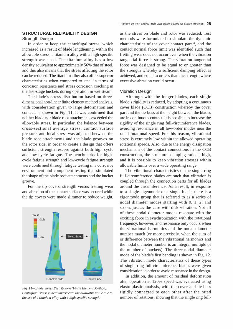
Titanium 50-inch and 60-inch Last-stage Blades for Steam Turbines 28
STRUCTURAL RELIABILITY DESIGNStrength Design
in order to keep the centrifugal stress, which increased as a result of blade lengthening, within the allowable stress, a titanium alloy with a high specific strength was used. The titanium alloy has a low density equivalent to approximately 56% that of steel, and this also means that the stress affecting the rotor can be reduced. The titanium alloy also offers superior characteristics when compared to steel in terms of corrosion resistance and stress corrosion cracking in the last-stage buckets during operation in wet steam.
The blade’s stress distribution based on three-dimensional non-linear finite element method analysis, with consideration given to large deformation and contact, is shown in Fig. 11. it was confirmed that neither blade nor blade root attachments exceeded the allowable stress. in particular, the balance between cross-sectional average stress, contact surface pressure, and local stress was adjusted between the blade root attachments and the blade grooves on the rotor side, in order to create a design that offers sufficient strength reserve against both high-cycle and low-cycle fatigue. The benchmarks for high-cycle fatigue strength and low-cycle fatigue strength were confirmed through fatigue testing in a corrosive environment and component testing that simulated the shape of the blade root attachments and the bucket groove.
For the tip covers, strength versus fretting wear and abrasion of the contact surface was secured while the tip covers were made slimmer to reduce weight,
as the stress on blade and rotor was reduced. Test methods were formulated to simulate the dynamic characteristics of the cover contact part(5), and the contact normal force limit was identified such that fretting wear does not occur even when the vibration tangential force is strong. The vibration tangential force was designed to be equal to or greater than the strength whereby a sufficient damping effect is achieved, and equal to or less than the strength where excessive abrasion would occur.
Vibration Design Although with the longer blades, each single
blade’s rigidity is reduced, by adopting a continuous cover blade (CCB) construction whereby the cover part and the tie-boss at the height between the blades are in continuous contact, it is possible to increase the rigidity of the single ring full-circumference blades, avoiding resonance in all low-order modes near the rated rotational speed. For this reason, vibrational stress is extremely low within the allowed operating rotational speeds. Also, due to the energy dissipation mechanism of the contact connections in the CCB construction, the structural damping ratio is high, and it is possible to keep vibration stresses within allowable limits over a wide operating range.
The vibrational characteristics of the single ring full-circumference blades are such that vibration is coupled through the connection parts for all blades around the circumference. As a result, in response to a single eigenmode of a single blade, there is a eigenmode group that is referred to as a series of nodal diameter modes starting with 0, 1, 2, and so on, just as the case with disk vibration. Not all of these nodal diameter modes resonate with the exciting force in synchronization with the rotational frequency, however, and resonance only occurs when the vibrational harmonics and the nodal diameter number match (or more precisely, when the sum of or difference between the vibrational harmonics and the nodal diameter number is an integral multiple of the number of buckets). The three-nodal-diameter mode of the blade’s first bending is shown in Fig. 12. The vibration mode characteristics of these types of single ring full-circumference blades were given consideration in order to avoid resonance in the design.
in addition, the amount of residual deformation after operation at 120% speed was evaluated using elasto-plastic analysis, with the cover and tie-boss rigidly connected to each other after the rated number of rotations, showing that the single ring full-
Fig. 11—Blade Stress Distribution (Finite Element Method).Centrifugal stress is held underneath the allowable value due to the use of a titanium alloy with a high specific strength.
Stress
High
Low Steam inlet
Concave side Convex side
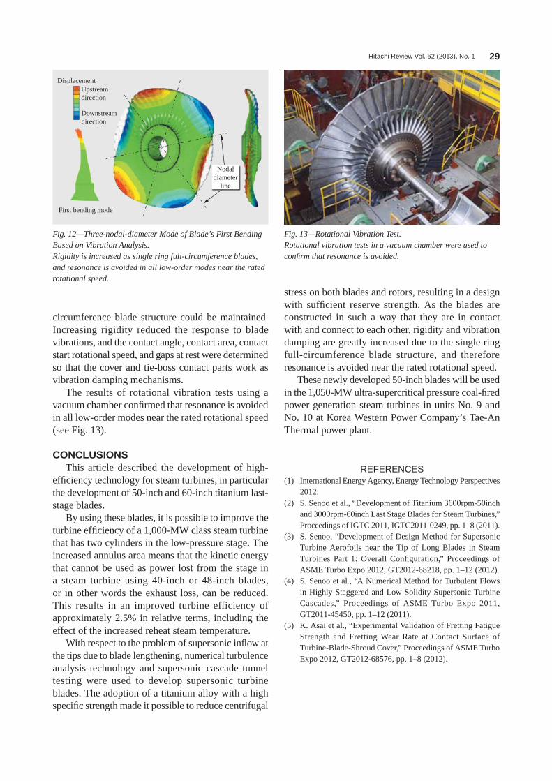
Hitachi Review Vol. 62 (2013), No. 1 29
circumference blade structure could be maintained. increasing rigidity reduced the response to blade vibrations, and the contact angle, contact area, contact start rotational speed, and gaps at rest were determined so that the cover and tie-boss contact parts work as vibration damping mechanisms.
The results of rotational vibration tests using a vacuum chamber confirmed that resonance is avoided in all low-order modes near the rated rotational speed (see Fig. 13).
CONCLUSIONSThis article described the development of high-
efficiency technology for steam turbines, in particular the development of 50-inch and 60-inch titanium last-stage blades.
By using these blades, it is possible to improve the turbine efficiency of a 1,000-MW class steam turbine that has two cylinders in the low-pressure stage. The increased annulus area means that the kinetic energy that cannot be used as power lost from the stage in a steam turbine using 40-inch or 48-inch blades, or in other words the exhaust loss, can be reduced. This results in an improved turbine efficiency of approximately 2.5% in relative terms, including the effect of the increased reheat steam temperature.
With respect to the problem of supersonic inflow at the tips due to blade lengthening, numerical turbulence analysis technology and supersonic cascade tunnel testing were used to develop supersonic turbine blades. The adoption of a titanium alloy with a high specific strength made it possible to reduce centrifugal
stress on both blades and rotors, resulting in a design with sufficient reserve strength. As the blades are constructed in such a way that they are in contact with and connect to each other, rigidity and vibration damping are greatly increased due to the single ring full-circumference blade structure, and therefore resonance is avoided near the rated rotational speed.
These newly developed 50-inch blades will be used in the 1,050-MW ultra-supercritical pressure coal-fired power generation steam turbines in units No. 9 and No. 10 at Korea Western Power Company’s Tae-An Thermal power plant.
REFERENCES(1) international Energy Agency, Energy Technology Perspectives
2012.(2) s. senoo et al., “Development of Titanium 3600rpm-50inch
and 3000rpm-60inch Last stage Blades for steam Turbines,” Proceedings of iGTC 2011, iGTC2011-0249, pp. 1–8 (2011).
(3) s. senoo, “Development of Design Method for supersonic Turbine Aerofoils near the Tip of Long Blades in steam Turbines Part 1: Overall Configuration,” Proceedings of AsME Turbo Expo 2012, GT2012-68218, pp. 1–12 (2012).
(4) s. senoo et al., “A Numerical Method for Turbulent Flows in highly staggered and Low solidity supersonic Turbine Cascades,” Proceedings of AsME Turbo Expo 2011, GT2011-45450, pp. 1–12 (2011).
(5) K. Asai et al., “Experimental Validation of Fretting Fatigue strength and Fretting Wear Rate at Contact surface of Turbine-Blade-shroud Cover,” Proceedings of AsME Turbo Expo 2012, GT2012-68576, pp. 1–8 (2012).
Fig. 13—Rotational Vibration Test.Rotational vibration tests in a vacuum chamber were used to confirm that resonance is avoided.
Fig. 12—Three-nodal-diameter Mode of Blade’s First Bending Based on Vibration Analysis.Rigidity is increased as single ring full-circumference blades, and resonance is avoided in all low-order modes near the rated rotational speed.
Displacement
First bending mode
Upstream direction
Downstream direction
Nodaldiameter
line

Titanium 50-inch and 60-inch Last-stage Blades for Steam Turbines 30
ABOUT THE AUTHORS
Kunio AsaiJoined Hitachi, Ltd. in 1997, and now works at the Department of Materials Research for Power Plants, Materials Research Center, Hitachi Research Laboratory. He is currently engaged in the research and development of highly reliable steam turbines, mainly in the areas of fretting fatigue, wear, corrosion fatigue, and damping. Mr. Asai is a member of the JSME, The Society of Materials Science, Japan (JSMS), and the GTSJ.
Shigeki Senoo, Ph.D., PE.Jp.Joined Hitachi, Ltd. in 1994, and now works at the Department of Turbomachinery Research, Energy and Environment Research Center, Hitachi Research Laboratory. He is currently engaged in the research and development of steam turbines, and in particular, research concerning unsteady wet steam flows and development of the last stage blade. Dr. Senoo is a member of the American Society of Mechanical Engineers (ASME), the Gas Turbine Society of Japan (GTSJ), The Japan Society of Fluid Mechanics (JSFM), and The Japan Society of Mechanical Engineers (JSME).
Goingwon LeeJoined Hitachi, Ltd. in 2001, and now works at the Steam Turbine Design and Service Department, Hitachi Works, Power Systems Company. He is currently engaged in the proposal, design, and development of steam turbines, and in particular, in steam path design and the proposal of main components for steam turbines.
Atsuhiro KurosawaJoined Hitachi, Ltd. in 1991, and now works at the Steam Turbine Design and Service Department, Hitachi Works, Power Systems Company. He is currently engaged in the proposal, design, and development of steam turbines, and in particular, in system design and the proposal of main components for steam turbines.
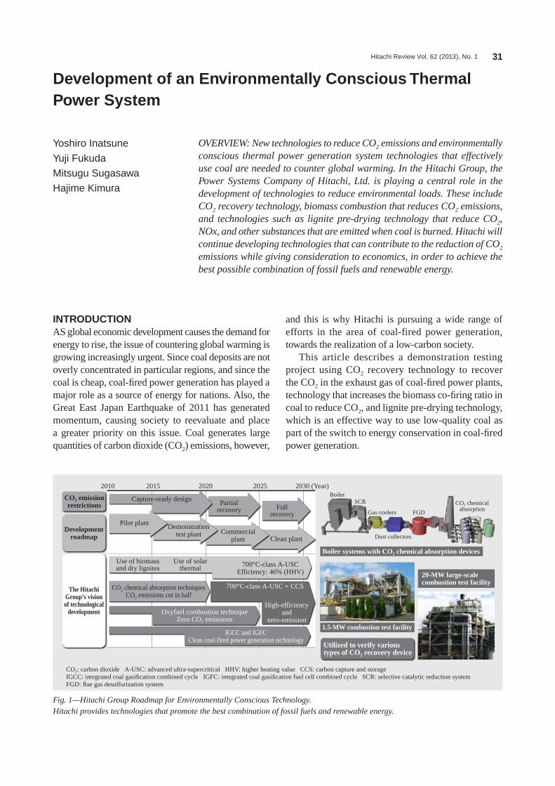
Hitachi Review Vol. 62 (2013), No. 1 31
Development of an Environmentally Conscious Thermal Power System
Yoshiro Inatsune
Yuji Fukuda
Mitsugu Sugasawa
Hajime Kimura
OVERVIEW: New technologies to reduce CO2 emissions and environmentally conscious thermal power generation system technologies that effectively use coal are needed to counter global warming. In the Hitachi Group, the Power Systems Company of Hitachi, Ltd. is playing a central role in the development of technologies to reduce environmental loads. These include CO2 recovery technology, biomass combustion that reduces CO2 emissions, and technologies such as lignite pre-drying technology that reduce CO2, NOx, and other substances that are emitted when coal is burned. Hitachi will continue developing technologies that can contribute to the reduction of CO2 emissions while giving consideration to economics, in order to achieve the best possible combination of fossil fuels and renewable energy.
INTRODUCTIONAs global economic development causes the demand for energy to rise, the issue of countering global warming is growing increasingly urgent. since coal deposits are not overly concentrated in particular regions, and since the coal is cheap, coal-fired power generation has played a major role as a source of energy for nations. Also, the Great East Japan Earthquake of 2011 has generated momentum, causing society to reevaluate and place a greater priority on this issue. Coal generates large quantities of carbon dioxide (CO2) emissions, however,
and this is why hitachi is pursuing a wide range of efforts in the area of coal-fired power generation, towards the realization of a low-carbon society.
This article describes a demonstration testing project using CO2 recovery technology to recover the CO2 in the exhaust gas of coal-fired power plants, technology that increases the biomass co-firing ratio in coal to reduce CO2, and lignite pre-drying technology, which is an effective way to use low-quality coal as part of the switch to energy conservation in coal-fired power generation.
Fig. 1—Hitachi Group Roadmap for Environmentally Conscious Technology.Hitachi provides technologies that promote the best combination of fossil fuels and renewable energy.
2010
Developmentroadmap
The HitachiGroup’s visionof technological
development
Pilot plant Demonstrationtest plant Commercial
plant Clean plant
Fullrecovery
Partialrecovery
Capture-ready design
Use of biomassand dry lignites
Use of solarthermal 700°C-class A-USC
Efficiency: 46% (HHV)
700°C-class A-USC + CCS
High-efficiencyand
zero-emission
CO2 emissionrestrictions
CO2 chemical absorption techniquesCO2 emissions cut in half
Oxyfuel combustion techniqueZero CO2 emissions
IGCC and IGFCClean coal-fired power generation technology
2015 2020 2025 2030 (Year)
Boiler systems with CO2 chemical absorption devices
1.5-MW combustion test facility
20-MW large-scalecombustion test facility
SCRBoiler
Gas coolers
Dust collectors
FGD
CO2 chemicalabsorption
Utilized to verify various types of CO2 recovery device
CO2: carbon dioxide A-UsC: advanced ultra-supercritical hhV: higher heating value CCs: carbon capture and storage iGCC: integrated coal gasification combined cycle iGFC: integrated coal gasification fuel cell combined cycle sCR: selective catalytic reduction system FGD: flue gas desulfurization system

Development of an Environmentally Conscious Thermal Power System 32
GLOBAL OPERATIONS IN ENVIRONMENTALLY CONSCIOUS TECHNOLOGY
hitachi has declared that it will “help reduce annual CO2 emissions by 100 million tons by 2025 through hitachi products and services” in its Environmental Vision 2025, and is promoting the development of technology towards the realization of a global low-carbon society. in particular, power generation departments are responsible for approximately 70% of this amount, and are proactively working to develop technologies that can contribute to reductions in CO2 while considering economics at the same time, in order to achieve the best possible combination of fossil fuels and renewable energy.
specifically, efficiency-improvement techniques include 700°C-class advanced ultra-supercritical thermal power generation (A-UsC) and integrated coal gasification combined cycle (iGCC) technologies, the use of solar thermal, photovoltaic, wind power, and biomass renewable energy sources, exhaust gas treatment technology including sCR, FGD, and chemical absorption and oxyfuel combustion techniques as CO2 recovery technology. Fig. 1 shows this development roadmap and vision, systems in which the equipment is used, and the exteriors of research facilities.
in developing these technologies, hitachi has built a global network across Japan, the UsA, and Europe, and is collaborating with local universities and national research institutes.
The development of materials that can withstand high temperatures and pressures is a key technology behind the 700°C-class A-UsC, and hitachi, Ltd. and hitachi’s European base hitachi Power Europe Gmbh are collaborating with power utilities and German universities on a wide range of joint development projects, from basic testing to in-plant testing.
As for chemical absorption techniques and exhaust gas treatments, hitachi, Ltd. and hitachi’s American base hitachi Power systems America, Ltd. have commissioned a U.s. Department of Energy (DOE) research institute with a joint project to verify chemical solvents. Also, hitachi, Ltd. and hitachi Power systems Canada Ltd. have started collaborating on a joint demonstration test project regarding CO2 recovery technology with Canada’s saskatchewan Power Corporation (saskPower).
in the area of renewable energy, hitachi is developing technology for mixed biomass combustion and the effective use of torrefaction biomass, as well
as high-speed load change technology for traditional thermal power. hitachi, Ltd. will also collaborate with hitachi Power Europe Gmbh to develop combustion technology for the high-moisture lignites (dry, direct combustion, etc.) that are expected to be used in increasingly larger quantities in southeast Asia and elsewhere (see Fig. 2).
CO2 RECOVERY TECHNOLOGY(1) Demonstration testing in Canada
hitachi has started a joint CO2 recovery demonstration testing project with saskPower. The test site is the 298-MW shand Power station on the outskirts of the city of Estevan, saskatchewan, which is owned by saskPower. This plant is located in the mid-western region of Canada, which is a center of development for CCs technology. Both companies have been cooperating to consolidate CO2 recovery technology and know-how, and are conducting comprehensive demonstration tests and evaluations of factors such as reliability and economic potential of the entire facility, with an aim towards the development of large commercial systems.
Fig. 3 shows the system flow for the demonstration testing facility. The exhaust gas is extracted from the chimney inlet and introduced to the absorber after Pre-scubber. The absorber injects solvent in the exhaust gas, absorbs CO2, and sends it to the desorber to be recovered CO2, after which a return to the absorber allows the system to recover CO2 in a continuous cycle. A design was adopted that considers issues
Europe Asia USA
Hitachi Power SystemsAmerica, Ltd.
Hitachi PowerEurope GmbH
EU• Darmstadt University of
Technology• Materials Testing Institute
(MPA), University of Stuttgart• RWTH Aachen University• Ruhr University Bochum• Technical University of
Denmark
Japan• Hiroshima
University• Nagoya
University• Kansai
University
USA• University of North Dakota
Energy & Environmental Research Center
• National Carbon Capture Center
Group companyRelated power utilityCollaborating university
Hitachi, Ltd. PowerSystems CompanyBabcock-Hitachi K.K.
Fig. 2—Hitachi Group Global Research Framework.Hitachi is promoting research and development in collaboration with group companies, universities, and national research institutes in each country.

Hitachi Review Vol. 62 (2013), No. 1 33
such as low emission measures for the solvent from the chimney, the effective use of solvent, and energy conservation.
Fig. 4 shows the rendering of CO2 recovery demonstration test facilities. The inside of the exterior wall of the CO2 demonstration test system is shown against the shand Power station building in the background. The tall, cylindrical object visible in the steel frame structure is the absorber, which will be located adjacent to the desorber. The tests are planned to start in the middle of 2014.
The conditions of the demonstration test plan are shown in Table 1. The scale of the system was decided based on a consideration of the scale of an actual future commercial system. it will process 120 t/d of CO2 with a CO2 recovery efficiency of 90%.
The CO2 solvent used in this testing is h3-1, which was developed based on technology cultivated during the actual flue gas demonstration testing conducted at Yokosuka Thermal Power station in joint research with Tokyo Electric Power Co., inc. in the first half of the 1990s.
The key areas in terms of performance in this process are the CO2 absorption of the solvent, as well as the reduction in energy required for recovering CO2. Fig. 5 shows a comparison between mono-ethanol amine (MEA), which is the standard amine solvent used for CO2, and h3-1. When compared with MEA, the required fluid volume of h3-1 solvent is reduced by 35%, and the required energy is reduced by 26%. These figures are the result of testing commissioned to the University of North Dakota’s Energy & Environmental Research Center (EERC) in the UsA. Based on this evaluation, the National Carbon Capture
Dust collectorBoiler Chimney
Exhaust gas
Processed gas
Water washing equipment
AbsorberHeat exchanger
Desorber
Reboiler Reclaimer
Low-pressure steam
Water washing equipment
Reflux drum
Recovered CO2
Prescrubber
One-fiftieth exhaust gas volume
Fig. 3—System Flow of CO2 Recovery Demonstration Testing Facilities in Canada.Exhaust gas are extracted from the chimney inlet and introduced to the absorber, after which the CO2 is absorbed into the solvent. After the CO2 is discharged by the desorber, the solvent is once again returned to the absorber in a continuous process of CO2 recovery.
Fig. 4—Artistic Rendering of CO2 Recovery Demonstration Testing Facilities.This rendering shows the CO2 recovery system against the background of the Shand Power Station building in Saskatchewan.
Item Design Condition
Fuel Canadian lignite
Exhaust gas volume 23,000 m3 N/h (wet)
Temperature 40°C
CO2 concentration 13%
CO2 recovery efficiency 90%
Capacity of CO2 recovery 120 t/d
TABLE 1. Conditions of Canadian Demonstration Testing PlanSpecifications are based on a consideration of scaling up for use in a commercial system.
−35% −26%
MEA
Source: Report of the Energy & Environmental Research Center, USA
Solv
ent f
low
rat
e (-
)(r
equi
red
flui
d vo
lum
e)
Hea
t dut
y (-
)(r
equi
red
ener
gy)
H3-1 MEA H3-1
Fig. 5—Solvent Performance Comparison.When compared to the standard solvent mono-ethanol amine (MEA), H3-1 solvent has been shown in tests to require a much lower fluid volume and much less energy.
MEA: mono-ethanol amine

Development of an Environmentally Conscious Thermal Power System 34
Center (NCCC), which is a national research center in the UsA, is also conducting evaluation tests.(2) Other demonstration testing
hitachi conducted gas-burning CO2 recovery tests at a Norwegian research institute in the fall of 2012. Expectations are high for the establishment of CO2 recovery technology for use with a variety of different fuels, including coal.
BIOMASS COMBUSTION TECHNOLOGYOverview
When the biomass co-firing ratio is increased for an existing coal-fired thermal power plant, a dedicated mill (pulverizer) must be added, resulting in issues such as a need for additional on-site power and space. in order to deal with these issues, the practical application of a combustion system is being promoted that utilizes the existing mill by securing a high co-firing ratio while reducing the costs associated with constructing and modifying facilities (see Fig. 6).
in view of the goal of reducing domestic CO2 emissions by 25%, the target co-firing ratio was set to 25 cal%. This development of the practical application of co-firing technology for existing pulverized-coal-fired boilers using only biomass is being conducted as a joint research project with the New Energy and industrial Technology Development Organization (NEDO) (fiscal 2010 to 2013). A description of the results of this research up to this point follows.
Development Results(1) Biomass pulverizing mills
Elemental test evaluations were conducted on multiple types of biomass including grass-based and wood-based materials, proposals were made for the appropriate structure to achieve the target co-firing ratio, and both safety (explosion-proofing) and corrosiveness were evaluated.
First, five types of biomass pellets were used in an elemental test of dedicated pulverizing. There are major differences in granularity and pulverizing force between the different types of biomass, and it has been confirmed that other than some biomass types (bark), granularity does not become finer than the feedstock granularity before pellet formation. This is necessary information for the design of a system (see Fig. 7).
Next, elemental tests were conducted of the appropriate structure to use in order to improve biomass discharging efficiency, which is a factor in achieving a high co-firing ratio through dedicated pulverizing. By reducing the vertical roller mill’s particle classification function, it was determined that it is possible to efficiently discharge the pulverized biomass outside the mill. This was achieved by using a double wall for primary classification (gravity classification), and a contracted vein for secondary classification (centrifugal classification). The exterior of the mill with this structure is shown in Fig. 8.
in the area of safety, methods of avoiding particle explosion were considered. switchgrass was confirmed to have a lower explosion limit oxygen (O2) concentration of 19 vol%, and so the mill was built
Fig. 6—Biomass Co-firing Facilities Utilizing Preexisting Combustion System.By converting existing coal mills (pulverizers) and burners so that they can also be used with biomass, 25 cal% biomass co-firing is achieved for the entire plant. A dual-use biomass mill can also be used for the combustion of coal, and can also continue functioning as a reserve mill.
Pulverization load: 200 kPaTable rotation speed: 50 r/minStockpile in pulverizer: 100 g
Gra
nula
rity
75
µm p
assa
ge r
ate
(%) 40
Switchgrass Liriope Bark Bagasse [Sugar cane residue]
Bamboo
30
20
10
0
Feedstock granularity (wet screening)
After pulverization (30 s)
Fig. 7—Pulverized Powder Generation Characteristics of Each Type of Pellet.Other than bark, pulverizability in excess of feedstock granularity was not confirmed. In particular, it was confirmed that switchgrass is more difficult to pulverize than other types of biomass.

Hitachi Review Vol. 62 (2013), No. 1 35
than for coal due to the lower ash content in the biomass, combustion efficiency was higher than for coal (see Table 2).(3) Biomass co-firing system
A large-scale combustion facility was used in tests to demonstrate that there are no combustion problems in the operation of a boiler furnace. For biomass, switchgrass used for the dedicated combustion burner, and cedar was used for the co-firing burner. For coal, Australian Bulga coal was used. A dedicated combustion burner that was verified during single burner testing was used for the dedicated combustion burner, a coal burner was used for the co-firing burner, and combustion performance was evaluated with the co-firing ratio around a target value of 25 cal% by adjusting between 20 cal% and 33 cal%. There were no problems in the ignition of the dedicated combustion burner, and a stable flame was formed. As the co-firing ratio increased, NOx was reduced, and almost no secondary CO was generated. in addition, there was almost no increase in unburned carbon in fly ash.
to operate with an inlet O2 concentration of 18 vol%.Chemical equilibrium computations were
performed in order to evaluate the gas composition of the exhaust gas recirculation system and analyze corrosiveness. in the case of switchgrass, sulfur trioxide (sO3) concentration is low, at 0.1 ppm in the mill outlet of the exhaust gas recirculation system (with an O2 concentration of 18 vol%), indicating that the risk of corrosion is low in the mill and pulverized coal piping.(2) Dedicated biomass burners
Combustion performance was evaluated for switchgrass using a single burner pilot plant for the combustion of biomass at the pilot scale. For the burner, a flame stability type NR-LE burner that can handle the combustion of lignite or other biomass with a low O2 carrier gas was used as the basic structure (see Fig. 9).
in the case of the aforementioned switchgrass, with carrier gas O2 concentration at 18 vol% conditions, the ability to combust in a stable manner with the burner load’s range of use between 40% and 70% was confirmed. The concentrations of nitrogen oxide (NOx) and carbon monoxide (CO) were the same or lower as the concentrations reached during the combustion of coal (Bulga coal in Australia). Although the unburned carbon in fly ash was higher
Pulverized coal pipe
Contracted vein
Coaling pipe
New classifier
Double wall
Fig. 8—Mills Using Both Biomass and Coal.The quantity of biomass discharged during pulverization was achieved by reducing the functions of primary and secondary classification. Development enabled combustion of coal by using the same structure.
High-performancedistributor
Pulverized coal(PC) concentrator
Fig. 9—Burners for Both Biomass and Coal.Stable combustion in a low-oxygen atmosphere was secured with an improved NR-LE burner developed for use with low-grade coal.
Fuel Switchgrass Coal (Australian Bulga)
NOx 137 ppm (6% O2) 136 ppm (6% O2)
CO 0 ppm (actual O2) 13 ppm (actual O2)
Unburned carbon in fly ash 8.7% 6.2%
Combustion efficiency 99.6% 99.0%
TABLE 2. Dedicated Combustion Characteristics of single Burner EquipmentSince the absolute amount of ash content is low in biomass, unburned carbon in fly ash of biomass has a relatively high value when compared to coal, and a favorable combustion efficiency. NOx, CO, and other emissions are equal to or lower than emissions during coal combustion.
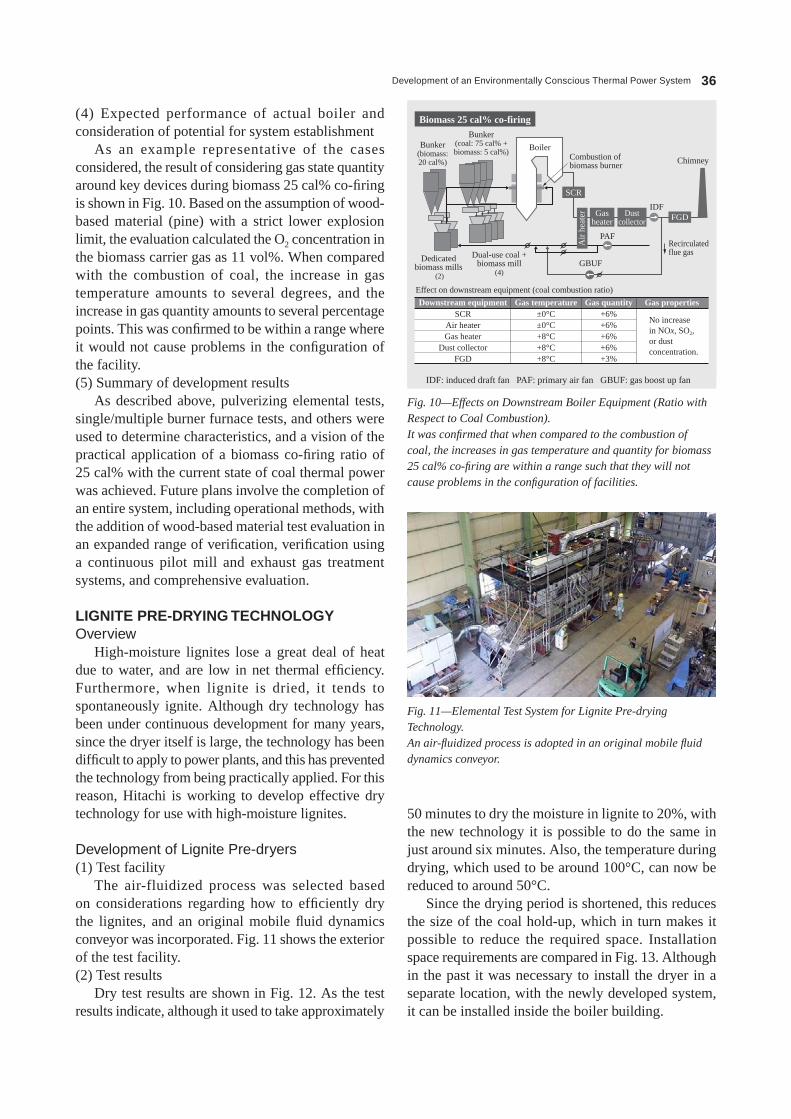
Development of an Environmentally Conscious Thermal Power System 36
50 minutes to dry the moisture in lignite to 20%, with the new technology it is possible to do the same in just around six minutes. Also, the temperature during drying, which used to be around 100°C, can now be reduced to around 50°C.
Since the drying period is shortened, this reduces the size of the coal hold-up, which in turn makes it possible to reduce the required space. Installation space requirements are compared in Fig. 13. Although in the past it was necessary to install the dryer in a separate location, with the newly developed system, it can be installed inside the boiler building.
(4) Expected performance of actual boiler and consideration of potential for system establishment
As an example representative of the cases considered, the result of considering gas state quantity around key devices during biomass 25 cal% co-firing is shown in Fig. 10. Based on the assumption of wood-based material (pine) with a strict lower explosion limit, the evaluation calculated the O2 concentration in the biomass carrier gas as 11 vol%. When compared with the combustion of coal, the increase in gas temperature amounts to several degrees, and the increase in gas quantity amounts to several percentage points. This was confirmed to be within a range where it would not cause problems in the configuration of the facility.(5) Summary of development results
As described above, pulverizing elemental tests, single/multiple burner furnace tests, and others were used to determine characteristics, and a vision of the practical application of a biomass co-firing ratio of 25 cal% with the current state of coal thermal power was achieved. Future plans involve the completion of an entire system, including operational methods, with the addition of wood-based material test evaluation in an expanded range of verification, verification using a continuous pilot mill and exhaust gas treatment systems, and comprehensive evaluation.
lIGNITE PRE-DRyING TEChNOlOGyOverview
High-moisture lignites lose a great deal of heat due to water, and are low in net thermal efficiency. Furthermore, when lignite is dried, it tends to spontaneously ignite. Although dry technology has been under continuous development for many years, since the dryer itself is large, the technology has been difficult to apply to power plants, and this has prevented the technology from being practically applied. For this reason, Hitachi is working to develop effective dry technology for use with high-moisture lignites.
Development of Lignite Pre-dryers(1) Test facility
The air-fluidized process was selected based on considerations regarding how to efficiently dry the lignites, and an original mobile fluid dynamics conveyor was incorporated. Fig. 11 shows the exterior of the test facility.(2) Test results
Dry test results are shown in Fig. 12. As the test results indicate, although it used to take approximately
Biomass 25 cal% co-firing
Bunker(biomass:20 cal%)
Bunker(coal: 75 cal% +biomass: 5 cal%) Boiler
Combustion ofbiomass burner
Effect on downstream equipment (coal combustion ratio)
Downstream equipmentSCR
Air heaterGas heater
Dust collectorFGD
Gas temperature±0°C±0°C+8°C+8°C+8°C
Gas quantity+6%+6%+6%+6%+3%
Gas properties
IDF
PAF
Dedicatedbiomass mills
(2)
Dual-use coal +biomass mill
(4)GBUF
Recirculatedflue gas
No increase in NOx, SO2, or dust concentration.
SCR
FGD
Chimney
Gasheater
Dustcollector
Air
hea
ter
Fig. 10—Effects on Downstream Boiler Equipment (Ratio with Respect to Coal Combustion).It was confirmed that when compared to the combustion of coal, the increases in gas temperature and quantity for biomass 25 cal% co-firing are within a range such that they will not cause problems in the configuration of facilities.
IDF: induced draft fan PAF: primary air fan GBUF: gas boost up fan
Fig. 11—Elemental Test System for Lignite Pre-drying Technology.An air-fluidized process is adopted in an original mobile fluid dynamics conveyor.

Hitachi Review Vol. 62 (2013), No. 1 37
An expected improvement of the target amount of approximately two points was confirmed in the net thermal efficiency.
As described above, the results meet the original development targets, and there are plans to carry out final verification tests while giving consideration to actual operation.(3) summary of development results
it was confirmed that when compared to previous systems, this development system greatly reduces drying time, temperature, and size (see Table 3).
CONCLUSIONSThis article provided an overview of a demonstration
testing project using CCs technology to recover the CO2 in the exhaust gas of coal-fired power plants, technology that increases the biomass co-firing ratio in
Furthermore, since past dryers operated at a high drying temperature, the low ph of the evaporated water would cause corrosion of the dryer’s materials, making it necessary to use stainless steel. The newly developed dryer operates at a lower drying temperature, and so the evaporated water has a ph equivalent to that of ordinary water, and therefore carbon steel can be used.
With regards to safety, the results of explosion tests conducted on pulverized powder extracted during testing confirm that explosions do not occur at the static electricity level. CO combustible gas was also monitored during testing, but CO was not generated.
Developed system Previous system
Drying possible at low temperature
150
Tem
pera
ture
(°C
)W
ater
con
tent
(%
)
100
50
0
0 10 20
Time (min)
30 40 50
60
40
20
0
Drying time reduced to one-eighth
Fig. 12—Results of Elemental Test of Lignite Pre-drying Technology.When compared to previous systems, the developed system cuts drying temperature in half and reduces drying time to one-eighth.
Coalbunker
Coalbunker
Dryer Dryer
Dry coalbunker
Dryer
Dry coal hopper
Coalingequipment
Coalingequipment
Dryer
Bug filter
MillMill
Inside boiler building
Coal bunker
Coalbunker
Coalbunker
Dryer Dryer Cooler
Dry coalbunker
Dryer
Dry coal hopper
Separate installation space
Greatly reduced in size
Coalingequipment
Coalingequipment
Dryer
Bug filter
Inside boiler building
Developed system Previous system
MillMill
Fig. 13—Comparison of Installation Space Requirements.The newly developed dryer does not require a separate installation space, and can be installed inside the boiler building.
Item Developed system Previous system
Water content in coal 60%→20% 60%→20%
Drying time Within 10 min Around 50 min
Dryer size Compact (installed inside boiler building)
installed in separate location
Dryer materials Carbon steel stainless steel
Temperature 60°C or less Approximately 100°C
safety (particle explosion) No particle explosion -
safety (combustible gas) No combustible gas -
Net thermal efficiency Two-point improvement -
TABLE 3. Performance Comparison between Lignite Pre-dryer Development system and Previous systemsThe developed system using power plant lignite pre-drying technology successfully reduces drying time, temperature, and size when compared with previous systems.

Development of an Environmentally Conscious Thermal Power System 38
(3) A. Baba, “Development of Practical Application of Co-firing Technology for Existing Pulverized-coal-fired Boilers Using Dedicated Biomass Pulverizing Method,” NEDO 2011 Biomass Energy Project Result Report Meeting (Feb. 2012) in Japanese.
(4) NEDO, Babcock-hitachi, “Development of Practical Application of Co-firing Technology for Existing Pulverized-coal-fired Boilers Using Dedicated Biomass Pulverizing Method,” NEDO 2011 Biomass Energy Project Mid-Year Annual Report (Mar. 2012) in Japanese.
(5) h. Kanemoto, “Development of Practical Application of Co-firing Technology for Existing Pulverized-coal-fired Boilers Using Dedicated Biomass Pulverizing Method,” The society of Powder Technology, Japan, Collection of Lecture Papers of the 48th summer symposium, 33-34 (Jul. 2012) in Japanese.
coal to reduce CO2, and lignite pre-drying technology, which is an effective way to use low-quality coal as part of the switch to energy conservation in coal-fired power generation.
hitachi will continue developing technologies that can contribute to the prevention of global warming.
REFERENCES(1) T. Kawasaki et al., “Development of CCs (Carbon Capture
and storage) Technology to Combat Climate Change,” hitachi Review 59, pp. 83–88 (Aug. 2010).
(2) Results of the Pilot-scale solvent Evaluations, 2010 NETL CO2 Capture Technology Meeting, september 13-17, 2010, Pittsburg, PA.
Yuji FukudaJoined Babcock-Hitachi K.K. in 1979, and now works at the Kure Research Laboratory. He is currently engaged in the development and management of boiler and AQCS-related R&D. Mr. Fukuda is a member of The Japan Society of Mechanical Engineers, The Japan Institute of Metals, and the Japan Society of Corrosion Engineering.
Hajime KimuraJoined Babcock-Hitachi K.K. in 1989, and now works at the Boiler Engineering Department, Thermal Power Division. He is currently engaged in the development and engineering of boiler technology for thermal power generation.
Yoshiro InatsuneJoined Babcock-Hitachi K.K. in 1981, and now works at the Development Promotion Department, Global R&D Division, Boiler and AQCS Division, Hitachi, Ltd. He is currently engaged in the promotion of R&D, especially in the field of CCS technology.
Mitsugu SugasawaJoined Babcock-Hitachi K.K. in 1981, and now works at the Energy System Division. He is currently engaged in the development of lignite systems.
ABOUT THE AUTHORS

Hitachi Review Vol. 62 (2013), No. 1 39
Near‑zero‑emission IGCC Power Plant Technology
Nobuo Nagasaki
Keisuke Sasaki
Tomoko Suzuki
Satoshi Dodo
Fumihiko Nagaremori
OVERVIEW: Hitachi is participating in the EAGLE project being undertaken jointly by the New Energy and Industrial Technology Development Organization (NEDO) and the Electric Power Development Co., Ltd. (J-POWER) and has been contracted by J-POWER to supply a complete set of equipment and provide support for trial operation. Drawing on the results from EAGLE, Hitachi is also involved in the large-scale experimental testing of 170-MW-class oxygen-blown coal gasification combined cycle power generation technology being undertaken by Osaki CoolGen Corporation. In addition to the design, fabrication, installation, and commissioning of an oxygen-blown, two-stage spiral-flow gasifier (capable of gasifiering around 1,100 t/d of coal) and combined cycle generation plant, the company also has an engineering role in which it acts as technical leader and coordinates the overall demonstration plant. Hitachi is also working to expand applications for the gasifier to include chemical feedstocks, and its aim is to reduce the construction cost of commercial IGCC systems by minimizing the gasifier construction costs through standardization and improved know-how. In Hitachi’s work on technical development aimed at achieving near-zero emissions (very low levels of CO2 and soot emissions), its approach is to seek to minimize loss of net thermal efficiency while also reducing construction costs.
INTRODUCTIONiT is estimated that total global power generation in 2030 will be about 1.7 times that in 2007, and it is also predicted that the use of coal-fired thermal power generation will continue to grow as it remains a key source of electric power(1). Because the price of coal is stable and cheap, with large minable reserves, and because it is not geographically concentrated, with coal mines located in politically stable regions, it is seen as remaining an important primary energy source for some time to come.
however, the amount of carbon dioxide (CO2) emitted per unit of energy produced from coal is high compared to other fossil fuels, such as natural gas or oil. This has created an expectation for clean coal technologies. There is also a trend toward introducing regulations on the per-unit emissions of CO2 from thermal power plants, and this creates a potential for requirements that are difficult to achieve in practice, such as higher efficiency and the use of biomass in multi-fuel combustion.
hitachi aims to expand its environmentally conscious coal-fired thermal power generation business to reduce CO2 emissions, and it is accelerating the development of clean coal technologies.
This article describes the results of pilot testing of the Coal Energy Application for Gas, Liquid and Electricity (EAGLE) project using an oxygen-blown,
Air
Coal
Gasifier
Steamturbine
Air
Flue
Gasturbine
Generator
Heat recoverysteam generator
Combustible gas (CO, H2, etc.)
H2
CO2, H2Transport and store CO2.
CO2 separation and capture
CO shift reaction: Inject steam into CO to convert to CO2 and H2
CO2 separation and capture: Separate and capture CO2
CO shift reaction vessel CO2 separation
and capture
OxygenAir separationequipment
Fig. 1—IGCC System Configuration.IGCC gasifies coal in a gasifier by converting it into combustible gas (CO and H2). This combustible gas is used to fuel a gas turbine. Exhaust heat from the gas turbine and reaction heat from the gasifier are recovered and used to produce steam. Using both the gas turbine and steam turbine to generate electric power boosts the efficiency of power generation.
iGCC: integrated coal gasification combined cycle CO: carbon monoxide h2: hydrogen CO2: carbon dioxide
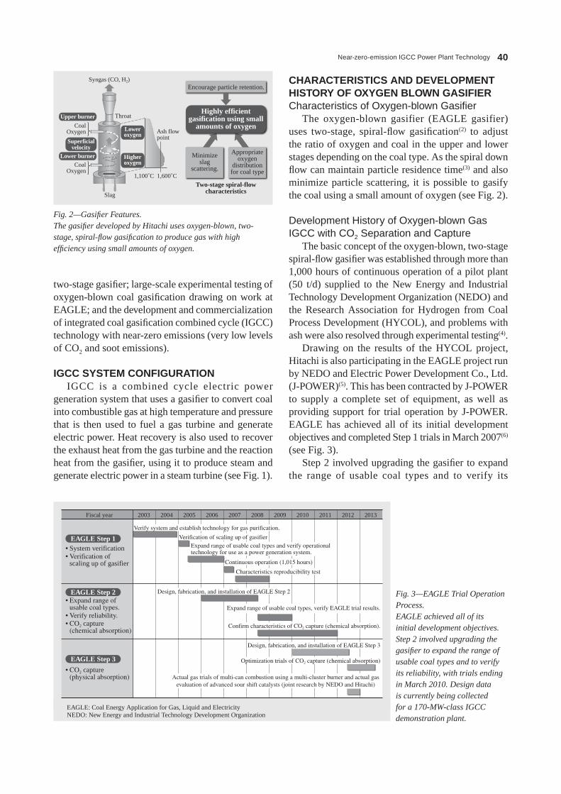
Near-zero-emission IGCC Power Plant Technology 40
two-stage gasifier; large-scale experimental testing of oxygen-blown coal gasification drawing on work at EAGLE; and the development and commercialization of integrated coal gasification combined cycle (iGCC) technology with near-zero emissions (very low levels of CO2 and soot emissions).
IGCC SYSTEM CONFIGURATIONiGCC is a combined cycle electric power
generation system that uses a gasifier to convert coal into combustible gas at high temperature and pressure that is then used to fuel a gas turbine and generate electric power. heat recovery is also used to recover the exhaust heat from the gas turbine and the reaction heat from the gasifier, using it to produce steam and generate electric power in a steam turbine (see Fig. 1).
CHARACTERISTICS AND DEVELOPMENT HISTORY OF OXYGEN BLOWN GASIFIERCharacteristics of Oxygen-blown Gasifier
The oxygen-blown gasifier (EAGLE gasifier) uses two-stage, spiral-flow gasification(2) to adjust the ratio of oxygen and coal in the upper and lower stages depending on the coal type. As the spiral down flow can maintain particle residence time(3) and also minimize particle scattering, it is possible to gasify the coal using a small amount of oxygen (see Fig. 2).
Development History of Oxygen-blown Gas IGCC with CO2 Separation and Capture
The basic concept of the oxygen-blown, two-stage spiral-flow gasifier was established through more than 1,000 hours of continuous operation of a pilot plant (50 t/d) supplied to the New Energy and industrial Technology Development Organization (NEDO) and the Research Association for hydrogen from Coal Process Development (hYCOL), and problems with ash were also resolved through experimental testing(4).
Drawing on the results of the hYCOL project, hitachi is also participating in the EAGLE project run by NEDO and Electric Power Development Co., Ltd. (J-POWER)(5). This has been contracted by J-POWER to supply a complete set of equipment, as well as providing support for trial operation by J-POWER. EAGLE has achieved all of its initial development objectives and completed step 1 trials in March 2007(6) (see Fig. 3).
step 2 involved upgrading the gasifier to expand the range of usable coal types and to verify its
Syngas (CO, H2)
CoalOxygen
CoalOxygen
Upper burner
Lower burner
Slag
Superficialvelocity
Loweroxygen
Higheroxygen
1,100˚C 1,600˚C
Throat
Ash flow point
Two-stage spiral-flowcharacteristics
Minimizeslag
scattering.
Appropriateoxygen
distributionfor coal type
Highly efficientgasification using small
amounts of oxygen
Encourage particle retention.
Fig. 2—Gasifier Features.The gasifier developed by Hitachi uses oxygen-blown, two-stage, spiral-flow gasification to produce gas with high efficiency using small amounts of oxygen.
Fig. 3—EAGLE Trial Operation Process.EAGLE achieved all of its initial development objectives. Step 2 involved upgrading the gasifier to expand the range of usable coal types and to verify its reliability, with trials ending in March 2010. Design data is currently being collected for a 170-MW-class IGCC demonstration plant.
• System verification• Verification of
scaling up of gasifier
EAGLE Step 1
EAGLE Step 2
EAGLE Step 3
Fiscal year 2003
Verify system and establish technology for gas purification.
Verification of scaling up of gasifierExpand range of usable coal types and verify operational technology for use as a power generation system.
Continuous operation (1,015 hours)
Characteristics reproducibility test
Design, fabrication, and installation of EAGLE Step 2
Expand range of usable coal types, verify EAGLE trial results.
Confirm characteristics of CO2 capture (chemical absorption).
Optimization trials of CO2 capture (chemical absorption)
Actual gas trials of multi-can combustion using a multi-cluster burner and actual gasevaluation of advanced sour shift catalysts (joint research by NEDO and Hitachi)
Design, fabrication, and installation of EAGLE Step 3
2004 2005 2006 2007 2008 2009 2010 2011 2012 2013
• Expand range of usable coal types.
• Verify reliability.• CO2 capture
(chemical absorption)
• CO2 capture (physical absorption)
EAGLE: Coal Energy Application for Gas, Liquid and Electricity NEDO: New Energy and industrial Technology Development Organization

Hitachi Review Vol. 62 (2013), No. 1 41
reliability, with trials running up until March 2010. While the EAGLE design was based on the results of the HYCOL project, problems arose that could not be foreseen in the preliminary analysis studies. The gasifier was further upgraded to deal with the problems at EAGLE and the suitability of these countermeasures verified in EAGLE Step 2.
Also, some of the existing equipment was diverted for use in world-leading experimental testing of CO2 separation and capture (chemical absorption) from syngas. The feed gas volume was 1,000 m3 (Normal)/h and CO2 capture was approximately 24 t/d. Technology for capturing CO2 from syngas (pre-combustion capture) is already in widespread use for capturing CO2 from natural gas, and its use in thermal power plants is under investigation around the world. An important factor when applying the technology to thermal power plants is to minimize the loss of net thermal efficiency when the CO2 capture equipment is installed. This requires reducing the amount of heat needed to regenerate the CO2 absorption fluid and fine-tuning the heat recovery system to minimize the reduction in the output of the steam turbine. EAGLE Step 2 used heated flash regeneration to optimize the operating conditions and fine-tune the heat recovery system to minimize the reduction in the output of the steam turbine, significantly reducing the loss of net thermal efficiency associated with CO2 capture from syngas while still achieving a CO2 capture ratio of 90% and a CO2 purity of 99%.
Step 3 of the project from 2011 to 2013 includes operating the gasifier to generate the coal gas required for trialing CO2 separation and capture (physical absorption) and also collecting design data for a 170-MW-class IGCC demonstration plant. A problem
with the CO2 separation and capture (chemical absorption) used in Step 2 was that the operation of heated flash regeneration caused foaming of the absorption fluid and its dispersal to the downstream side. In response, a new flash drum with appropriate dimensions was installed prior to commencing Step 3, and then operation during the Step 3 trials kept within a range suitable for these dimensions. This succeeded in eliminating the dispersion to the downstream side caused by foaming of the absorption fluid.
In joint research by NEDO and Hitachi, actual gas trials of multi-can combustion using a multi-pore coaxial jet burner (cluster burner) and advanced sour shift catalysts are planned in FY2012.
PLANS FOR EXPERIMENTAL TESTING OF OXYGEN-BLOWN IGCC WITH CO2 SEPARATION AND CAPTURE
J-POWER and The Chugoku Electric Power Co., Inc. established Osaki CoolGen Corporation in July 2009 to make efficient progress on oxygen-blown IGCC power generation technology and CO2 separation and capture technology.
For Phase 1 of the Osaki CoolGen Project, Osaki CoolGen Corporation will commence construction of a large-scale demonstration plant for 170-MW-class oxygen-blown coal gasification technology in March 2013. The aims are to verify the basic performance (power generation efficiency and environmental performance), operating characteristics (startup and shutdown time, rate of change of load, etc.), and economics of the oxygen-blown IGCC system. Next, the plan for Phase 2 is to retrofit the IGCC demonstration plant built for Phase 1 with CO2 separation and capture equipment, and to
Fiscal year
Design, fabrication, and installation
Design, fabrication,and installation
Design, fabrication, and installation
Conceptual design oftechnical investigation
Trialoperation
Experimentaltesting
Conceptual designof applicable
technology assessment
Experimentaltesting
Construction starts.
Development ofrevolutionary
technology forcoal gasificationwith CO2 capture
Optimization
Environmentalassessment
Oxygen-blown IGCC
CO2
separationand capture
IGCC/IGFCwith integrated
CO2 capture
Trial operation starts.
2009 2010 2011 2012 2013 2014 2015 2016 2017 2018 2019 2020 2021 2022
Cons
truct
ion
and
expe
rimen
tal t
estin
g
Fig. 4—Process of IGFC Experimental Testing.The experimental testing is to be split into three phases, comprising respectively oxygen-blown IGCC, CO2 separation and capture, and IGCC/IGFC with integrated CO2 capture.IGFC: integrated coal gasification fuel cell combined cycle

Near-zero-emission IGCC Power Plant Technology 42
verify the system’s basic performance, equipment reliability, operating characteristics, economics, and environmental performance. For Phase 3, the plans include adding a fuel cell to the iGCC system with CO2 separation and capture built in Phase 2 to verify precision gas purification technology and the potential for using coal gas in fuel cells, and also performing appropriate verification testing of an integrated coal gasification fuel cell combined cycle (iGFC) power generation system(7) (see Fig. 4).
in addition to the design, fabrication, installation, and commissioning of an oxygen-blown, two-stage spiral-flow gasifier with a coal processing capacity of about 1,100 t/d, the 170-MW-class combined cycle power generation equipment, and the electrical and control equipment for the large-scale experimental testing of the 170-MW-class oxygen-blown coal gasification technology in Phase 1, hitachi also has an engineering role in which it acts as technical leader and coordinates the overall demonstration plant. The plans for trial operation in Phase 1 include technical verification of the scaling up of the gasifier, establishment of technology for the operation and control of the gasifier, and total system verification of oxygen-blown iGCC.
The generator output of the Osaki CoolGen Project is in the 170-MW class, and the 40.5% higher heating value (hhV) target for net thermal efficiency will make it one of the most efficient in the world for a system of this output class, demonstrating the high efficiency of oxygen-blown iGCC. Verification of this result would imply that a commercial iGCC system could achieve a net thermal efficiency of 46% (hhV), accelerating the commercialization of highly efficient iGCC.
BOOSTING NET THERMAL EFFICIENCY OF OXYGEN‑BLOWN IGCC AND REDUCING CO2 EMISSIONSDeployment of Oxygen-blown IGCC
The net thermal efficiency of iGCC can be increased through the use of technology that boosts the efficiency of a natural-gas-fired gas turbine by increasing its temperature. The net thermal efficiency of the oxygen-blown iGCC with a higher gas turbine temperature (step 2) is 46% (hhV), and it can reduce CO2 emissions by roughly 20% compared to the latest pulverized coal thermal power generation. For an oxygen-blown gasifier, CO2 can be captured from feed gas with a high CO2 concentration (approximately 40%) pressurized to between 2.5 MPa and 3.0 MPa (pre-combustion capture). As the flow rate of the gas being processed is lower than it is when capturing CO2 from the boiler exhaust gas (post-combustion capture), the equipment can be made smaller than that used for capturing CO2 from the boiler exhaust gas, and the loss of net thermal efficiency is minimized.
Achieving practical coal-fired thermal power generation with near-zero emissions by combining iGCC with carbon capture and storage (CCs) makes it possible to combine CO2 emissions reduction with the efficient use of coal. As the high concentration of fuel components in the gasifier syngas (CO and h2, etc.) for oxygen-blown gas iGCC means that the fuel cell voltage can be increased, using a highly efficient generation system that incorporates a fuel cell can reduce CO2 emissions by approximately 30% compared to the latest coal-fired thermal power plants in Japan(8) (see Fig. 5 and Fig. 6).
Fig. 5—Outlook for Oxygen-blown IGCC.IGCC allows net thermal efficiency to be increased through the use of technology that boosts the efficiency of the gas turbine by increasing its temperature. The loss of net thermal efficiency resulting from CO2 capture can be reduced by capturing the high concentration of CO2 in the pressurized fuel gas.
ACC(LNG-fired
combined cyclepower generation)
1,300°C-class GT GT temperatureincrease (Step 1)
Higher efficiency due to higher GT temperature
Technology transfer
1,300°C-class GT(Net 40.5% HHV)(Osaki CoolGen)
170-MW class 200-MW class 370-MW class 600-MW class
+ CO2 separationand capture
(Net 32% HHV)
+ CO2 separationand capture
(Net 35% HHV)
+ CO2 separationand capture
(Net 40% HHV)
Reduce loss of efficiency due to CO2 capture.
Gasification co-productionof chemical feedstock
Use of AHATin IGCC
IGFC (Net 53% HHV)
+ CO2 separationand capture
(Net 42% HHV)
GT temperatureincrease (Step 1)(Net 43% HHV)
GT temperatureincrease (Step 2)(Net 46% HHV)
GT temperatureincrease (Step 3)(Net 48% HHV)
GT temperatureincrease (Step 2)
Technology transfer
GT temperatureincrease (Step 3)
Technology transfer
IGCC
ACC: advanced combined cycle LNG: liquefied natural gas GT: gas turbine hhV: higher heating value AhAT: advanced humid air turbine

Hitachi Review Vol. 62 (2013), No. 1 43
temperature (step 2) to commercialize a highly efficient iGCC with a generator output in the 300-MW to 370-MW class and net thermal efficiency of 46% (hhV).
PROGRESS ON ZERO‑EMISSION IGCC THROUGH DEPLOYMENT IN MULTIPLE APPLICATIONSDevelopment Strategy for Zero-emission IGCC
An issue with iGCC demonstration plants is the high cost of construction. it is recognized that the predicted levels of construction costs for commercial plants are different depending on the development stage, with the predicted construction cost being highest for a commercial plant at the demonstration stage during which the issues to be verified and project risks are clarified. After that greater know-how and standardization bring the construction cost down. With the iGCC currently at the demonstration stage, one strategy for reducing the construction cost of the oxygen-blown, two-stage spiral-flow gasifier is to extend its application to include use as a gasifier for chemical feedstocks. Reducing the cost of gasifier construction also helps reduce the construction costs for commercial and zero-emission iGCC.
in the case of gasifiers for chemical feedstock and zero-emission iGCC, hitachi is working on the following four initiatives (in addition to enhancing know-how and standardization) to reduce construction costs and increase efficiency (see Fig. 7).(1) improve cold gas efficiency by using CO2 circulation gasification.(2) Use direct quenching for syngas cooling and humidification.(3) Use advanced sour shift catalyst.(4) Establish technology for low-nitrogen-oxide (NOx) combustion using cluster burner.
Strategy for Commercialization of Oxygen-blown IGCC
Trial operation in Phase 1 of the Osaki CoolGen Project is intended to commercialize iGCC through technical verification of the scaling up of the gasifier, establishment of technology for the operation and control of the gasifier, and total system verification of oxygen-blown iGCC. The gasifier will be scaled up by a factor of less than 10 to maintain the two-stage spiral-flow characteristics and minimize the risks associated with scaling up.
The target is to build the first commercial system with a gasifier capacity less than 10 times the 150 t/d capacity of the EAGLE gasifier by 2020. The first commercial iGCC will include the higher gas turbine temperature (step 1), have a coal processing capacity of 1,300 t/d, a generator output in the 200-MW class, and net thermal efficiency of 43% (hhV).
similarly, a target of the latter half of the 2020s has been set for using iGCC with higher gas turbine
Fig. 6—CO2 Emission Reductions for IGCC and IGCC + CCS.IGCC (for 1,500°C-class gas turbines) has 20% lower CO2 emissions than a conventional coal-fired thermal power generation plant. Adding CO2 capture to IGCC (IGCC + CCS) results in near-zero emissions of CO2.
Unit: kg-CO2/ kWh
Conventionalcoal-fired
thermal powergeneration
Source: Report by Central Research Institute of Electric Power Industry
LNG-firedcombined
cycle powergeneration
Photovoltaicpower
generation
IGCC IGCC + CCS30% CO2
capture90% CO2
capture
CO
2 em
issi
ons
per
unit
of e
nerg
y ge
nera
ted
1.0
0.8
0.4
0.6
0.2
0.0
Water
Coal, O2
CO2CO2
circulationgasification
CO2 compression,
transportation, and storage
H2 supply for production
of chemical feedstocks
Clusterburner
Advanced sourshift catalyst
Water scrubberhumidificationDehalogenation
Direct quenchinggasifier
CO2
H2
H2CO2
captureunit
Gas turbine Steam turbineGasifier
Waterscrubber
Dust removal
CO shiftreactor
Fig. 7—Configuration of Gasifier for Chemical Feedstocks and Zero-emissions IGCC.Technologies have been established for the efficient production of hydrogen from coal: (1) Improved cold gas efficiency resulting from CO2 circulation gasification, (2) Use of direct quenching for syngas cooling and humidification, (3) Use of advanced sour shift catalyst, and (4) Technology for low-NOx combustion using cluster burner.

Near-zero-emission IGCC Power Plant Technology 44
Use of Direct Quenching for Syngas Cooling and Humidification
At the Osaki CoolGen demonstration project, the syngas is cooled to between 350°C and 400°C by the heat exchanger in the upper part of the gasifier and the syngas cooler (sGC), dust removal is performed using a char filter and halogen removal. Further cooling occurs in the water scrubber, and then the sulfur components of the syngas are removed in a gas purifier. The sensible heat in the syngas is recovered as steam in the sGC and the heat exchanger in the upper part of the gasifier. This steam is then supplied to the steam turbine to improve generation efficiency (see Fig. 1).
Direct quenching cools the high-temperature syngas at the exit of the gasifier by injecting a water spray. Direct quenching can reduce gasifier construction costs because it eliminates the sGC and allows the heat exchanger in the upper part of the gasifier to be made smaller. When applied to iGCC, however, the sensible heat of the syngas cannot be recovered in the sGC and the heat exchanger in the upper part of the gasifier and this significantly reduces the net thermal efficiency. in the case of gasifiers for chemical feedstocks and zero-emission iGCC, meanwhile, a shift reaction with the CO in the syngas is used to produce h2 and CO2, and therefore the steam recovered from the sGC and the heat exchanger in the upper part of the gasifier needs to be added into the syngas. Direct quenching not only cools the syngas using a water spray, it also has the effect of humidifying the syngas(9). Direct quench gasification uses a water spray to cool the gas to between 350°C and 400°C, after which dust removal is performed using a char filter, and then a water scrubber is used to perform halogen removal and further cool the syngas to between 180°C and 200°C. The ratio of
Improved Cold Gas Efficiency Resulting from CO2 Circulation Gasification
in gasifiers for chemical feedstocks and zero-emission iGCC, the generated CO2 is used as the coal transport medium in the gasifier. Because the mixing gas in the gasifier is CO2 instead of nitrogen, the concentration of impurities (nitrogen) in the syngas is reduced. Also, gasifying coal in the presence of CO2 reduces the amount of oxygen used and improves, by approximately 3.5 points, the cold gas efficiency that represents the yield ratio for the syngas (ratio of syngas calorific value to coal heat input). As CO2 has a higher heat capacity than nitrogen, and as the reaction between coal and CO2 is endothermic, changing the coal transport medium from nitrogen to CO2 reduces the gasifier temperature. As the ash in a spouted bed gasifier is collected as molten slag, the gasification temperature needs to be kept above the ash melting point.
EAGLE has an oxygen-blown two-stage spiral-flow gasifier. in CO2 circulation gasification, the flow of oxygen to the lower burner is increased to maintain the lower stage gasification temperature and ensure a stable downward flow of slag. in addition to offsetting the increased flow of oxygen to the lower burner, reducing the flow of oxygen to the upper burner in accordance with the reduced oxygen requirement resulting from the use of CO2 gasification also allows the cold gas efficiency of the gasifier to be increased. The improved cold gas efficiency resulting from CO2 circulation gasification is a feature of two-stage gasification and is one of the superior technical features of gasifiers for chemical feedstocks and the EAGLE gasifier for zero-emission iGCC (see Fig. 8).
Fig. 8—Improved Cold Gas Efficiency Resulting from CO2 Circulation Gasification.The cold gas efficiency and product yield are increased by adjusting the oxygen ratios of the upper and lower burners respectively (Lower stage: Increase oxygen ratio to maintain gasification temperature, Upper stage: Reduce oxygen ratio to lower overall oxygen ratio).
Syngas(CO, H2) Total oxygen ratio
Reduce upper stage oxygen ratio to reduce amount of oxygen.
Reduce upper stage oxygen ratio to reduce amount of oxygen.
Ash melting point
1,600°C1,100°CHigh
Oxygen distribution
High oxygen ratio
Low oxygen ratio
C + 0.5 O2+0.05 N2N2 transport
CO2 transport
= 1.00 CO + 0.05 N2
C + 0.475 O2 + 0.05 CO2
C + CO2
(1)
(2)
(3)
= 1.05 CO
= 2 CO ↓ Temperature drop
Cold gas efficiency: +3.5%Oxygen quantity: -5%
CO2 transportN2 transport
CO2 transportN2 transport
Temperature distribution
Low
Increase lower stage oxygen ratio to make up for temperature drop.
Increase lower stage oxygen ratio to make up for temperature drop.
Upper burner
Lower burner
CoalOxygen
Transport gas
CoalOxygen
Transport gas
Slag
N2: gaseous nitrogen

Hitachi Review Vol. 62 (2013), No. 1 45
the CO shift reaction falls with increasing temperature, the amount of steam added is increased to boost this theoretical conversion ratio. This has the result of reducing the amount of steam available to the steam turbine and cutting the generation efficiency. in response, hitachi has developed a shift catalyst that has a fast reaction rate at low temperature, and is able to achieve a CO-to-CO2 conversion ratio close to the theoretical value using a small amount of steam(10). Laboratory testing has confirmed the ability of this technology to cut the amount of steam required for the CO shift reaction by more than 30%. By reducing the amount of added steam, a CO-to-CO2 conversion ratio of 96% can be achieved for the moisture concentration of h2O/CO = 1.2 resulting from the direct quenching and water scrubber humidification process described above. Therefore, the need to add steam from the steam cycle can be eliminated. Compared to using the previous catalyst, this results in a one point reduction in the loss of net thermal efficiency for a CO2 capture ratio of 90% (see Fig. 10).
in joint research planned for FY2012, NEDO and hitachi, Ltd. will install two small-scale catalyst test systems, each with a capacity of 50 m3 (Normal)/h, at the EAGLE pilot plant at J-POWER’s Wakamatsu Research institute and conduct actual gas trials.
water (h2O)/carbon monoxide (CO) in the syngas at the exit of the water scrubber is about 1.2 or more.
hitachi’s direct quench process has the following three features.(1) As the quenched syngas is dry, with a temperature of between 350°C and 400°C, a char filter can be used for dust removal.(2) halogen removal can be performed in the water scrubber through the washing effect of the cooling water.(3) The humidity needed for the advanced sour shift catalyst (described below) can be achieved without the supply of external steam.
Because the process can remove dust and halogens, it is suitable for use with commercial shift reaction catalysts and CO2 absorption processes (see Fig. 9).
Advanced Sour Shift CatalystZero-emission iGCC uses some of the steam
supplied to the steam turbine for a CO shift reaction. This diminishes the amount of steam that reaches the steam turbine and reduces the power generation efficiency in proportion to the amount of CO2 captured. To improve power generation efficiency when performing CO2 capture, it is necessary to carry out the shift reaction efficiently using a small amount of steam.
shift catalysts used in the past have had a slow reaction rate at low temperatures, meaning that higher temperatures needed to be used to accelerate the reaction. As the theoretical CO-to-CO2 conversion ratio (theoretical ratio of CO to CO2 at equilibrium) in
Filter
Syngas
WaterDrain
Water
Water spray
SGC removed
Water scrubbing
Water discharge
Coal
Cyclone
Knockoutdrum
Fig. 9—Use of Direct Quenching to Eliminate SGC.Gasification with direct quenching uses a water spray to cool the syngas to between 350°C and 400°C. After dust removal by a char filter, the syngas is then cooled to between 180°C and 200°C in the water scrubber where halogen removal is also performed.
sGC: syngas cooler
Advanced sour shift catalyst
Theoretical CO conversion ratio
Advanced sour shift catalyst
100
80
60
40
20
0200 300 400 500
Temperature (°C)
Previouscatalyst
Advanced sourshift catalyst
(Temperature: 250°C, Pressure: 2.4 MPa)
Approximately30% reduction
Stea
m q
uant
ity (
H2O
/CO
)
CO
con
vers
ion
ratio
(%
)
Previous catalyst
H2O/CO=1.8
Pressure: 0.1 MPa
Fig. 10—Advanced Sour Shift Catalyst.Hitachi has developed a shift catalyst that achieves a fast reaction rate at low temperature and a CO → CO2 conversion ratio that is close to the theoretical value while using a small amount of steam, and has confirmed that steam use can be cut by approximately 30%.
h2O: water
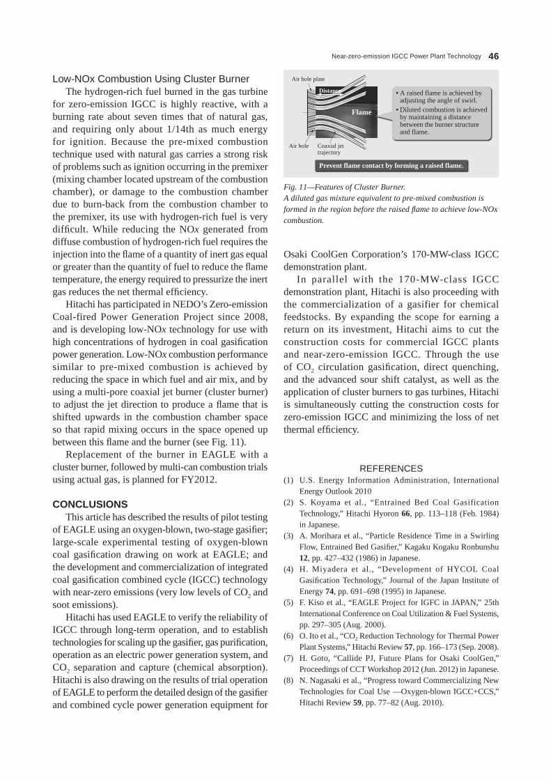
Near-zero-emission IGCC Power Plant Technology 46
Osaki CoolGen Corporation’s 170-MW-class iGCC demonstration plant.
in parallel with the 170-MW-class iGCC demonstration plant, hitachi is also proceeding with the commercialization of a gasifier for chemical feedstocks. By expanding the scope for earning a return on its investment, hitachi aims to cut the construction costs for commercial iGCC plants and near-zero-emission iGCC. Through the use of CO2 circulation gasification, direct quenching, and the advanced sour shift catalyst, as well as the application of cluster burners to gas turbines, hitachi is simultaneously cutting the construction costs for zero-emission iGCC and minimizing the loss of net thermal efficiency.
REFERENCES(1) U.s. Energy information Administration, international
Energy Outlook 2010(2) s. Koyama et al., “Entrained Bed Coal Gasification
Technology,” hitachi hyoron 66, pp. 113–118 (Feb. 1984) in Japanese.
(3) A. Morihara et al., “Particle Residence Time in a swirling Flow, Entrained Bed Gasifier,” Kagaku Kogaku Ronbunshu 12, pp. 427–432 (1986) in Japanese.
(4) h. Miyadera et al., “Development of hYCOL Coal Gasification Technology,” Journal of the Japan institute of Energy 74, pp. 691–698 (1995) in Japanese.
(5) F. Kiso et al., “EAGLE Project for iGFC in JAPAN,” 25th international Conference on Coal Utilization & Fuel systems, pp. 297–305 (Aug. 2000).
(6) O. ito et al., “CO2 Reduction Technology for Thermal Power Plant systems,” hitachi Review 57, pp. 166–173 (sep. 2008).
(7) h. Goto, “Callide PJ, Future Plans for Osaki CoolGen,” Proceedings of CCT Workshop 2012 (Jun. 2012) in Japanese.
(8) N. Nagasaki et al., “Progress toward Commercializing New Technologies for Coal Use —Oxygen-blown iGCC+CCs,” hitachi Review 59, pp. 77–82 (Aug. 2010).
Low-NOx Combustion Using Cluster BurnerThe hydrogen-rich fuel burned in the gas turbine
for zero-emission iGCC is highly reactive, with a burning rate about seven times that of natural gas, and requiring only about 1/14th as much energy for ignition. Because the pre-mixed combustion technique used with natural gas carries a strong risk of problems such as ignition occurring in the premixer (mixing chamber located upstream of the combustion chamber), or damage to the combustion chamber due to burn-back from the combustion chamber to the premixer, its use with hydrogen-rich fuel is very difficult. While reducing the NOx generated from diffuse combustion of hydrogen-rich fuel requires the injection into the flame of a quantity of inert gas equal or greater than the quantity of fuel to reduce the flame temperature, the energy required to pressurize the inert gas reduces the net thermal efficiency.
hitachi has participated in NEDO’s Zero-emission Coal-fired Power Generation Project since 2008, and is developing low-NOx technology for use with high concentrations of hydrogen in coal gasification power generation. Low-NOx combustion performance similar to pre-mixed combustion is achieved by reducing the space in which fuel and air mix, and by using a multi-pore coaxial jet burner (cluster burner) to adjust the jet direction to produce a flame that is shifted upwards in the combustion chamber space so that rapid mixing occurs in the space opened up between this flame and the burner (see Fig. 11).
Replacement of the burner in EAGLE with a cluster burner, followed by multi-can combustion trials using actual gas, is planned for FY2012.
CONCLUSIONSThis article has described the results of pilot testing
of EAGLE using an oxygen-blown, two-stage gasifier; large-scale experimental testing of oxygen-blown coal gasification drawing on work at EAGLE; and the development and commercialization of integrated coal gasification combined cycle (iGCC) technology with near-zero emissions (very low levels of CO2 and soot emissions).
hitachi has used EAGLE to verify the reliability of iGCC through long-term operation, and to establish technologies for scaling up the gasifier, gas purification, operation as an electric power generation system, and CO2 separation and capture (chemical absorption). hitachi is also drawing on the results of trial operation of EAGLE to perform the detailed design of the gasifier and combined cycle power generation equipment for
Air hole plate
• A raised flame is achieved by adjusting the angle of swirl.
• Diluted combustion is achieved by maintaining a distance between the burner structure and flame.
Prevent flame contact by forming a raised flame.
Air hole Coaxial jettrajectory
Distance
Flame
Fig. 11—Features of Cluster Burner.A diluted gas mixture equivalent to pre-mixed combustion is formed in the region before the raised flame to achieve low-NOx combustion.
Hitachi Review Vol. 62 (2013), No. 1 47
temperature shift Catalyst,” 43rd Autumn Meeting of The society of Chemical Engineers, Japan, A206 (sep. 2011) in Japanese.
(9) F. Kiso et al., “A simulation study on the Enhancement of the shift Reaction by Water injection into a Gasifier,” Energy 36, pp. 4032–4040 (Jul. 2011).
(10) T. sasaki et al., “Development of s-resistant, Low-
Keisuke SasakiJoined Hitachi, Ltd. in 1981, and now works at the OCG Project Management Division, Thermal Power Systems Division, Thermal Power Business Division, Power Systems Company. He is currently engaged in management of the Osaki CoolGen Project and commercialization of zero-emission IGCC.
Satoshi DodoJoined Hitachi, Ltd. in 1994, and now works at the Energy and Environment Research Center, Hitachi Research Laboratory. He is currently engaged in research and development of syngas-fired low-NOx combustors. Mr. Dodo is a member of The Visualization Society of Japan and the Gas Turbine Society of Japan.
Nobuo NagasakiJoined Hitachi Engineering Co., Ltd. in 1979, and now works at the OCG Project Management Division, Thermal Power Systems Division, Thermal Power Business Division, Power Systems Company. He is currently engaged in the development of technology for IGCC with CO2 capture. Mr. Nagasaki is a member of The Japan Society of Mechanical Engineers (JSME).
Tomoko SuzukiJoined Hitachi, Ltd. in 1992, and now works at the Department of Thermal Power & Water Purification Systems Research, Hitachi Research Laboratory. She is currently engaged in the development of the technology for IGCC with CO2 capture. Ms. Suzuki is a member of the JSME and The Society of Chemical Engineers, Japan.
Fumihiko NagaremoriJoined Babcock-Hitachi K.K. in 1983, and now works at the Coal Gasification System Center, Plant Engineering Division, Kure Division, Babcock-Hitachi K.K. He is currently engaged in gasifier development and coordination of a IGCC system.
ABOUT THE AUTHORS
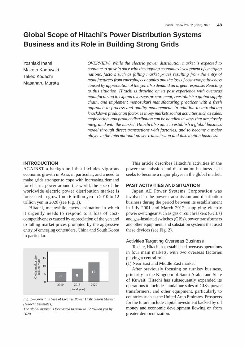
Hitachi Review Vol. 62 (2013), No. 1 48
Global Scope of Hitachi’s Power Distribution Systems Business and its Role in Building Strong Grids
Yoshiaki Inami
Makoto Kadowaki
Takeo Kodachi
Masaharu Murata
OVERVIEW: While the electric power distribution market is expected to continue to grow in pace with the ongoing economic development of emerging nations, factors such as falling market prices resulting from the entry of manufacturers from emerging economies and the loss of cost-competitiveness caused by appreciation of the yen also demand an urgent response. Reacting to this situation, Hitachi is drawing on its past experience with overseas manufacturing to expand overseas procurement, reestablish a global supply chain, and implement monozukuri manufacturing practices with a fresh approach to process and quality management. In addition to introducing knockdown production factories in key markets so that activities such as sales, engineering, and product distribution can be handled in ways that are closely integrated with the market, Hitachi also aims to establish a global business model through direct transactions with factories, and to become a major player in the international power transmission and distribution business.
INTRODUCTIONAGAiNsT a background that includes vigorous economic growth in Asia, in particular, and a need to make grids stronger to cope with increasing demand for electric power around the world, the size of the worldwide electric power distribution market is forecasted to grow from 6 trillion yen in 2010 to 12 trillion yen in 2020 (see Fig. 1).
hitachi, meanwhile, faces a situation in which it urgently needs to respond to a loss of cost-competitiveness caused by appreciation of the yen and to falling market prices prompted by the aggressive entry of emerging contenders, China and south Korea in particular.
This article describes hitachi’s activities in the power transmission and distribution business as it seeks to become a major player in the global market.
PAST ACTIVITIES AND SITUATIONJapan AE Power systems Corporation was
involved in the power transmission and distribution business during the period between its establishment in July 2001 and March 2012, supplying electric power switchgear such as gas circuit breakers (GCBs) and gas-insulated switches (Giss), power transformers and other equipment, and substation systems that used these devices (see Fig. 2).
Activities Targeting Overseas BusinessTo date, hitachi has established overseas operations
in four main markets, with two overseas factories playing a central role.(1) Near East and Middle East market
After previously focusing on turnkey business, primarily in the Kingdom of saudi Arabia and state of Kuwait, hitachi has subsequently expanded its operations to include standalone sales of Giss, power transformers, and other equipment, particularly to countries such as the United Arab Emirates. Prospects for the future include capital investment backed by oil money and economic development flowing on from greater democratization.
Glo
bal m
arke
t siz
e(t
rilli
on y
en)
(Fiscal year)
15
10
5
02010
6 812
2015 2020
Fig. 1—Growth in Size of Electric Power Distribution Market (Hitachi Estimates).The global market is forecasted to grow to 12 trillion yen by 2020.

Hitachi Review Vol. 62 (2013), No. 1 49
(2) Chinese marketBusiness activities include sales of equipment
through technical collaborations with local companies and a joint-venture company with the state Grid Corporation of China, and parts sales involving the supply of main components for equipment from
Japan. Demand from the electric power distribution sector is anticipated to continue growing along with the expansion of the Chinese economy.(3) North American market
hitachi sells GCBs through a local subsidiary. Ongoing demand is anticipated from the replacement of aging equipment and investment in stronger grids.(4) southeast Asian market
hitachi operates a maintenance business along with Gis sales through a sales and engineering office in the Republic of singapore and a factory in the Republic of indonesia. Growth in demand driven by economic development is forecasted to continue.(5) Overseas factories
Plants in indonesia and China manufacture parts and components for Gis and GCB products. The components are first sent to plants in Japan for assembly and final testing prior to delivery to various markets.
Market ConditionsMarket prices have fallen significantly since 2009,
driven by factors such as the bursting of the Middle East bubble that followed on from the sub-prime loan crisis in the UsA, and the entry into overseas markets of emerging manufacturers from countries such as China and south Korea. Amid a loss of cost-
(a) (b)
(c) (d)
Fig. 2—Typical Products of Electric Power Distribution Business.The photographs show 550-kV GCBs (a), a 380-kV power transformer (b), a 245-kV GIS (c), and a 380-kV substation system in the Kingdom of Saudi Arabia (d).
GCB: gas circuit breaker Gis: gas-insulated switch
Parts process Standard unit assembly
GCB unit
DS/ES unit
Transportation
MarketLCC CT
CH
LCC
BUS
BUSCT
CT CH
GCB
DS/ES
Transportation
Testing
Assembly
Unit assembly
Procurement ofoptional units
BUS unit
In-house production
Parts machining
Localvendor
Japan
Semi-finished products
Purchased parts
Special parts,important components
Unit production factory Knockdown production factory
Insp
ectio
n
Fig. 3—Knockdown Production of GISs.Production of standard units is centralized at part production factories. Knockdown production factories are used to procure optional units, assemble finished products, and handle testing and delivery.
Ds: disconnecting switch Es: earthing switch BUs: busbar LCC: local control cubicle CT: current transformer Ch: cable head
Global Scope of Hitachi’s Power Distribution Systems Business and its Role in Building Strong Grids 50
implemented a knockdown system that includes the manufacture and procurement of components other than standard units, the customization of products to specific customer specifications, the assembly of these along with standard units imported from a part production factory, and their shipment and testing (see Fig. 3). This provides each factory with a clear mission, reduces exchange rate risk through local production for local supply, and allows technical support from Japan to be delivered in a focused and efficient manner.
Regarding the flow of products and contracts that went through Japanese factories in the past, improvements to the supply chain to allow direct dealings between part production factories and knockdown production factories have made transactions and the flow of goods more efficient (see Fig. 4). Furthermore, hitachi is proceeding with the implementation and construction of a new global supply chain in which the Japanese side handles tasks such as management of each factory, management of the overall supply chain, and technical guidance and operational support for each part production factory and knockdown production factory.
Greater Use of Overseas ProcurementAs well as seeking to make its switchgear products
more competitive through reconstruction of the global supply chain, hitachi is also aiming to improve the
competitiveness caused by appreciation of the yen, manufacturing practices capable of producing a large number of models to suit the varying specifications demanded by different markets or customers have become a challenge for overseas factories. Also needed is a shift toward business practices that are more closely integrated with markets, instead of operations being based primarily out of Japan, as in the past.
CONSTRUCTION OF GLOBAL PRODUCTION SYSTEMSupply Chain Reconstruction
To overcome the difficulties described above, hitachi revised its range of export-market Giss with the aim of improving productivity to reduce costs without compromising quality, rationalizing the range from 33 down to six main models. in addition to defining the main components not subject to customer-specific specifications as standard units, the existing facility at AE Power (suzhou) EhV switchgear Corporation in China was designated a part production factory and made to specialize in the production of standard units.
PT. hitachi Power systems indonesia in southeast Asia, hitachi hVB, inc. in North America, and CET AE Power (shandong) high-Voltage switchgear Co., Ltd. in China were each designated knockdown production factories. Based around these plants, hitachi has
ChinaSDC
ChinaSZC
MiddleEast
SoutheastAsia
China
Japan
NorthAmerica
Market
Previous supply chain
Productsordered
from Japan
Productsordered
from overseasfactory
New supply chain
Contract flow Product flow
MarketFactory
MarketOverseasfactory
Knockdownproduction factory
Support Support
SZC and HPSI (partial)HVB, HPSI, and SDC
Part productionfactory
Japan
Japan Overseasplant
Japanesevendor
Japanesevendor
Localvendor
LocalvendorMarket
AmericaHVB
Republic ofIndonesia HPSI
Fig. 4—Reconstruction of Global Supply Chain for GISs.Hitachi aims to service key markets from knockdown production factories in China, Indonesia, and USA. In addition to making transactions more efficient through the construction of new supply chains with direct transactions between knockdown production factories and part production factories, Hitachi will also provide each factory with support from Japan.
sDC: CET AE Power (shandong) high-Voltage switchgear Co., Ltd. sZC: AE Power (suzhou) EhV switchgear Corporation hPsi: PT. hitachi Power systems indonesia hVB: hitachi hVB, inc. * sZC and sDC use their company names from prior to hitachi, Ltd.’s takeover of businesses from Japan AE Power systems Corporation (as of October 2012).

Hitachi Review Vol. 62 (2013), No. 1 51
As it is anticipated that greater use will be made of these transformers in the future, both in Japan and elsewhere, hitachi is seeking to strengthen its competitiveness by taking active steps to use overseas products as well as supporting detailed engineering.
Efficiency Improvement for Overseas Production Processes
To make the provision of production instructions to each factory more efficient, maintain consistent quality, and strengthen management of the global supply chain, hitachi is proceeding with improvements to the production processes that utilize information technology (iT). in the past, most work instructions and records at factories have been paper-based. hitachi is currently working on introducing the implementation of work management and navigation systems to Gis, GCB, and other assembly work. The systems use tablet personal computers and other mobile devices for paperless work instructions with three-dimensional (3D) models of each operation step and the collection of realtime work records. They facilitate more efficient provision of technical instruction, training, and quality management to overseas factories (see Fig. 6). in the future, it is anticipated that the systems will also be used for applications such as work at remote sites or support for working at user sites.
GLOBAL BUSINESS OPERATIONSin addition to building a global production system,
hitachi is also taking steps to operate globally with overseas facilities taking a central role. This includes competitiveness of its power transformers, especially
those intended for export markets, by taking active steps to use overseas parts and materials without compromising the high product reliability built up through past experience. hitachi also expects to gain a further increase in orders through the overseas marketing of high-added-value products that demand a high level of engineering capabilities, such as the phase shifting transformers that are one of hitachi’s strengths (see Fig. 5).
One example is the use of overseas-made on-load tap changers, radiators, cores, and other key power transformer components in phase shifting transformers intended for overseas markets. Phase shifting transformers are particularly effective devices for the efficient operation and stabilization of power systems. They increase overall power transmission capacity through the control of power flow in systems with a loop configuration, and improve reliability and reduce power loss across entire loop systems.
X1
X2
PX
1
Phase shifting transformer
Load side230-kV inter-tank connection
On-load tap changer
Radiator bank for main power transformer
Radiator bank forseries transformer
Supply side
Main powertransformer
Seriestransformer
XT
X2
P
Before installation After installation
• Power flow is split by impedances X1 and X2.
• Transmission power flow can no longer increase once any route reaches its limit, even if the other route still has unused capacity.
• The addition of the impedance due to the phase shifting transformer changes the distribution of power flow.
• The distribution of power flow between the two routes can be changed by adjusting the voltage of the phase shifting transformer.
Fig. 5—Structure Diagram and Benefits of Phase Shifting Transformers Intended for Overseas Markets.Phase shifting transformers increase overall power transmission capacity through the control of power flow in systems with a loop configuration, and improve reliability and reduce power loss across entire loop systems.
P: power
Assemblycell 1
Assemblycell 2
Server
Network
Procedures andmanagement information
3D animation
Video of actual work
Records
Navigation in the formof 3D animations aswell as tool lists andother work instructions
Data stored on web server to allow for overseas operations
Transmission of control limits and actual measurements
Control limitsand other
work records
PC 1 PC 2
Digital tools
Fig. 6—Structure of Work Management and Navigation System.The system performs realtime work navigation and recording, and uses touch-panel PCs to display information that includes a 3D animation for each action, which tools to use, and control limits.
3D: three-dimensional PC: personal computer
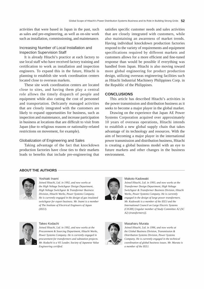
Global Scope of Hitachi’s Power Distribution Systems Business and its Role in Building Strong Grids 52
satisfies specific customer needs and sales activities that are closely integrated with customers, while also maintaining an awareness of market trends. having individual knockdown production factories respond to the variety of requirements and equipment specifications required by different markets and customers allows for a more efficient and fine-tuned response than would be possible if everything was handled from Japan. hitachi is also moving toward more global engineering for product production design, utilizing overseas engineering facilities such as hitachi industrial Machinery Philippines Corp. in the Republic of the Philippines.
CONCLUSIONSThis article has described hitachi’s activities in
the power transmission and distribution business as it seeks to become a major player in the global market.
Drawing on the experience that Japan AE Power systems Corporation acquired over approximately 10 years of overseas operations, hitachi intends to establish a new global supply chain that takes advantage of its technology and resources. With the aim of becoming a major player in the international power transmission and distribution business, hitachi is creating a global business model with an eye to future markets and other changes in the business environment.
activities that were based in Japan in the past, such as sales and pre-engineering, as well as on-site work such as installation, commissioning, and maintenance.
Increasing Number of Local Installation and Inspection Supervision Staff
it is already hitachi’s practice at each factory to use local staff who have received factory training and certification to work as installation and inspection engineers. To expand this in the future, hitachi is planning to establish site work coordination centers located close to overseas markets.
These site work coordination centers are located close to sites, and having them play a central role allows the timely dispatch of people and equipment while also cutting the cost of personnel and transportation. Delicately managed activities that are closely integrated with the customers are likely to expand opportunities for business, such as inspection and maintenance, and increase participation in business at locations that are difficult to visit from Japan (due to religious reasons or nationality-related restrictions on movement, for example).
Globalization of Engineering and SalesTaking advantage of the fact that knockdown
production factories have close ties to their markets leads to benefits that include pre-engineering that
Makoto KadowakiJoined Hitachi, Ltd. in 1993, and now works at the Transformer Design Department, High Voltage Switchgear & Transformer Business Division, Hitachi Works, Power Systems Company. He is currently engaged in the design of large power transformers. Mr. Kadowaki is a member of the IEEJ and the International Council on Large Electric Systems (CIGRE) [regular member of Study Committee A2 (SC A2) (transformers)].
Masaharu MurataJoined Hitachi, Ltd. in 1996, and now works at the Global Business Division, Transmission & Distribution Systems Division, Power Systems Company. He is currently engaged in the technical coordination of global business issues. Mr. Murata is a member of the IEEJ.
Yoshiaki InamiJoined Hitachi, Ltd. in 1992, and now works at the High Voltage Switchgear Design Department, High Voltage Switchgear & Transformer Business Division, Hitachi Works, Power Systems Company. He is currently engaged in the design of gas insulated switchgear for export business. Mr. Inami is a member of The Institute of Electrical Engineers of Japan (IEEJ).
Takeo KodachiJoined Hitachi, Ltd. in 1992, and now works at the Procurement & Sourcing Department, Hitachi Works, Power Systems Company. He is currently engaged in procurement for transformers and substation projects. Mr. Kodachi is a VE Leader, Society of Japanese Value Engineering certified.
ABOUT THE AUTHORS

Hitachi Review Vol. 62 (2013), No. 1 53
Power System Technologies for Reliable Supply of Electric Power and Wide‑area Grids
Hiroo Horii, P.E.jp
Masahiro Yatsu
Takashi Aihara
OVERVIEW: A renewable energy feed-in tariff took effect in Japan in July 2012, and is expected to accelerate the adoption of photovoltaic power generation and other forms of renewable energy. Due to restrictions in the building of photovoltaic and wind power plants, there are expected to be increasing numbers of cases where such plants are built in remote locations far from the places where large amounts of energy are consumed, both in Japan and internationally. For this reason, problems related to the stabilization of power grids between energy production and consumption locations may grow serious. To deal with this situation, Hitachi is working towards the realization of power supply stabilization and wide-area interconnection by pursuing efforts in power system stabilizers, SVCs, energy storage systems, high voltage DC transmission systems, and other power grid technologies.
INTRODUCTIONAs electric power systems are reinvented around the world, the use of renewable energy is expanding at a rapid pace. Although the objectives of energy policies differ from country to country, the presence of renewable energy grows on a daily basis, with approximately half of the power generation capacity added in 2011 being from power generation equipment for use in generating renewable energy(1). Photovoltaic power generation, wind power generation, and other forms of renewable energy are gaining traction in Japan as well, with measures such as a renewable energy feed-in tariff being implemented with the goal of realizing a low-carbon society.
Photovoltaic and wind power generation is affected by weather-induced changes in output, lightning strikes, and other disturbances that can trip the entire system. in order to secure high-quality electric power, it is necessary to be able to adjust voltage and frequency and take measures to maintain the stability of the power grid. Furthermore, if the power generation equipment for photovoltaic or wind power generation is built offshore or in a vast isolated area far from cities and other energy load centers, power system stabilization measures will be necessary for the transmission, distribution, and power grid systems used to transmit electricity to the energy load centers.
By integrating transmission and distribution systems and information and communication technology (iCT), hitachi aims to achieve strong
grids that offer optimized control and strength in a power grid, as well as smart grids that offer expanded consumer services (see Fig. 1).
This article describes hitachi’s efforts in contributing to power grid stabilization through the use of strong grid technology and smart grid technology.
Fig. 1—Overview of Strong and Smart Grids.An overview of a strong grid, which provides optimized control and strengthening of a power grid using renewable energy, and a smart grid, which provides expanded consumer services.
Windpower Photovoltaic
Power plant
Substation
Optimized controlof power grid
Consumer services
EMS DMS
Storagebatteries
EV charging system
AMIBEMS/HEMS
Transmission grid
Powerdistribution grid
Stro
ng g
rid
Smar
t gr
id
EMs: energy management system DMs: distribution management system EV: electric vehicle AMi: advanced metering infrastructure BEMs: building and energy management system hEMs: home energy management system

Power System Technologies for Reliable Supply of Electric Power and Wide-area Grids 54
system (isC) integrated power system stabilizer was developed to solve this problem by adding the ability to simultaneously deal with transient stability, voltage, and frequency to an online TsC system(3).
The isC system uses the following functions to carry out transient stability and voltage fluctuation countermeasures when a fault occurs that causes no network splitting:(1) Generator shedding to maintain transient stability when a grid fault occurs (2) Additional generator shedding to prevent a reduction in transient voltage(3) Reactive power control with shunt compensators to prevent voltage fluctuations after generator shedding
Transient stability countermeasures are performed using these functions after a fault occurs, making it possible to stabilize the voltage within the target range.
What follows is a description of the processing that occurs in a master station system using an isC system to implement the aforementioned functions (see Fig. 2).
Online data input(SV, TM)
Online data
Systemcontrolserver
Analysis servers
Transmissionto slave stations
(30-s cycles)
State estimation andgrid model creation
Selection of equipment to apply power control to for maintaining transient
stability
Selection of equipment to apply power control to for
preventing voltage loss
Selection of phase modifying control
equipment to maintain voltage after power control
Control information output to slave stations
Fig. 2—System Configuration and Processing Flow of ISC Master Station System Delivered to Chubu Electric Power Co., Inc.At the integrated stability control (ISC) system’s master station, online data is loaded and approximately 100 grid failure scenarios are considered in order to calculate stability as well as to execute stabilization countermeasures in areas such as transient stability and voltage. The results of these countermeasures are sent to the slave stations in 30-s cycles. The stability calculations and countermeasure processing require the capabilities of multiple high-speed blade servers computing in parallel.
sV: super vision TM: telemeter
SYSTEM TECHNOLOGIES FOR IMPLEMENTING STRONG AND SMART GRIDS Power System Stabilization Systems
When a transmission line is hit by lightning, or when some other fault occurs in a power grid, a loss of voltage can cause a momentary reduction in the amount of electric power transmitted, and a power swing will occur after the fault is eliminated. This phenomenon is called “power grid transient stability.” if there is a large swing, the disturbance can spread throughout the entire grid, resulting in a major power outage. The transmission lines of a power grid are required to operate within the operational limitations, and the operational limitations caused by transient stability are particularly dominant when it comes to large, long-distance electric power transmission grids. To deal with this problem, power system stabilizers can rapidly and optimally shed (isolate) generators from the grid, thereby removing the operational limitations caused by transient stability and drastically improving the total tranasfer capability (TTC).
An “online transient stability control” (online TsC) system has been put into practical use as a typical power system stabilizer. This online TsC system is a grid stability system that combines iCT with advanced reliability evaluation that is made possible with calculations based on information such as the power flow and bus voltage(2) derived from the power system. The online TsC consists of a central-TsC and several remote-TsCs. The central-TsC system incorporates power grid data, calculating detailed transient stability in advance by envisioning large numbers of grid faults (contingency cases) such as lightning strikes. For the contingency cases that would cause the grid to become unstable, the system determines which stabilization countermeasures to take (generator shedding, etc.), and communicates this information to the remote-TsCs installed at the substation. if a grid fault actually occurs, the stabilization control is quickly applied by the remote-TsC. The system performs the optimized measures for various network faults autonomously. Also, since the TTC can be boosted during ordinary operation as well, this provides greater flexibility in running generators, making highly economical operation possible.
Another problem facing large, long-distance electric power transmission grids is that when a fault occurs in the power grid, countermeasures must be taken at the same time to deal with both voltage and frequency, while also dealing with the transient stability issue. The integrated stability control

Hitachi Review Vol. 62 (2013), No. 1 55
The system control server performs state estimation using the online data derived from the power grid to obtain a consistent grid model. Next, the analysis server runs detailed stability simulations concerning around 100 different possible grid fault scenarios, in order to select the optimal equipment to use for applying stabilization control. Finally, stabilization control information for each envisioned fault is sent to the slave stations. Power system stabilization is performed based on this information when an actual fault occurs.
in the future, many renewable energy sources such as photovoltaic and wind power generation will be connected to the grid. however, stability control systems with predefined parameters will have difficulty handling such a grid because of its many unpredictable factors. Online TsC systems and isC systems, in contrast, can minimize these factors because these systems analyze the network stability with realtime data derived from the power network. Also, the power grid must be stabilized in an even smarter fashion based on the installation to the power grid of static var compensators (sVCs), storage batteries, and other such equipment.
SVCsAn sVC is a system that uses power electronics
equipment to control reactive power at high speed. Although there are a number of different types of sVCs, thyristor controlled reactors (TCR) and static synchronous compensators (sTATCOM) are typical.
A TCR controls the on and off periods of thyristors connected in an reverse-parallel fashion, and changes the average strength of the flowing current in order to control phase lagging reactive power (see Fig. 3).
Phase advanced reactive power is also controllable by combining with electric power capacitors.
A sTATCOM is a device that controls phase advanced and phase lagging reactive power at high speed through the amplitude and phase of voltage outputted by a self-commutated converter that is comprised of insulated-gate bipolar transistors (iGBT) and other self-turn-off semiconductor devices (see Fig. 4).
since voltage can also be controlled by controlling reactive power, sVCs play an active role in suppressing the voltage fluctuations that occur when the output of renewable energy fluctuates due to changes in the amount of sunshine or wind conditions, or when load changes rapidly in an electric furnace. The degree to which the power grid can operate in a stable manner without large voltage drops in response to tripped generators or transmission lines, or sudden increases in load, is referred to as “voltage stability.” An sVC is a device that can contribute to improvements in voltage stability.
in addition to voltage stability, a power grid is also characterized in terms of “synchronization stability.” synchronization stability refers to the degree to which the power grid can continue to operate by recovering to a stable state without loss of synchronization in a running synchronous generator after transmission line failures or other disturbances occur in the power grid. since synchronization stability is mainly related to active power, and sVCs only control reactive power,
Fig. 3—Schematic of TCR Circuit.By controlling thyristors, a thyristor controlled reactor (TCR) changes the average strength of current flowing in a reactor, thereby controlling phase lagging reactive power.
Self-exciting converter
Converter transformer
Controller
Current directive value
Voltage directive value
Gate signal
DC smoothingcapacitor
Current controlcomputation PWM
Carrier
Fig. 4—Schematic of STATCOM Circuit.A static synchronous compensator (STATCOM) is a system that uses self-commutated conversion equipment comprised of insulated-gate bipolar transistors (IGBTs) and other semiconductor devices to control reactive power at high speed.
PWM: pulse width modulation

Power System Technologies for Reliable Supply of Electric Power and Wide-area Grids 56
one might assume that an sVC would be unnecessary. however, active power between two points is related to voltage amplitude, and so by controlling voltage with an sVC, it is also possible to control active power. Therefore, sVCs also provide an effective means of improving synchronization stability. Fig. 5 shows waveforms in an example simulation of the use of a sTATCOM to improve synchronization stability. in this example, a generator loses synchronization due to a grid failure with no sTATCOM installed. A sTATCOM is then installed on the grid and provides suitable control, enabling stable operation.
hitachi has an extensive track record in manufacturing sVCs. Typical examples are shown in Table 1. The TCRs delivered to the Noshiro Thermal Power station owned by Tohoku Electric Power Co., inc. are mainly aimed at providing both voltage fluctuation, suppression and power swing suppression, but also contribute to improvements in synchronization stability(4).
The sTATCOM delivered to the hokuriku Electric Power Company’s Fushiki substation features flicker countermeasures. When there is massive load fluctuation, as can occur with an arc furnace, electric lamps and other devices can flicker due to voltage fluctuation. The main purpose of the Fushiki substation’s sTATCOM is to suppress this flicker(5).
Overseas, hitachi delivered a power distribution grid sTATCOM in 2011 to the major British power distribution companies Western Power Distribution (south West) plc and Western Power Distribution (south Wales) plc (WPD). This sTATCOM is being used by the smart grid demonstration experiment carried out by WPD as a part of the low-carbon network projects promoted by the UK’s energy regulator. The main purpose of this sTATCOM is to suppress the voltage changes caused by renewable energy, which is known for its instability, thereby continuously providing the power grid with stable electric power. As a future step, there are plans to add three similar sTATCOMs in a test of a distribution grid voltage control system.
Energy Storage Systemshitachi provides energy storage systems as energy
storage solutions for a wide range of purposes, such as peak-shifting of electric power, and power system stabilization for when wind or photovoltaic power generation is introduced. Electric power utilities stipulate grid interconnection requirements for power fluctuation levels separately in order to stabilize the
power system when large amounts of renewable energy are introduced. Energy storage systems are provided as power fluctuation alleviation solutions to meet these requirements, and are comprised of lead-acid batteries with an expected life of 17 years (LL1500-W model), power conditioning systems (PCs), and the control equipment necessary to operate the systems in an optimal fashion. This control equipment monitors the state of power fluctuation of renewable energy, as well as the charging state of storage batteries, and
3.00
2.00
1.00
0.00
PPG
ele
ctri
city
out
put a
ctiv
e pa
rt (
P.U
.)
Time (s)
No STATCOM installed:generator loses synchronization
STATCOM installed and stabilization controlled:power swings converge
−1.
00−
2.00
0.00 1.00 2.00 3.00 4.00 5.00 6.00 7.00 8.00 9.00
2.00
1.50
1.00
0.50
PPG
ele
ctri
city
out
put a
ctiv
e pa
rt (
P.U
.)
Time (s)
0.00
−0.
50
0.00 1.00 2.00 3.00 4.00 5.00 6.00 7.00 8.00 9.00
Fig. 5—Improving Synchronization Stability with STATCOM.This simulation example shows how grid operations can be made stable by installing a STATCOM for appropriate control.
PPG: pulse pattern generator
Rated capacity System Year
deliveredMajor
purpose
Noshiro Thermal Power station 100 MVA TCR 1994 Power swing
suppression
Fushiki substation 20 MVA sTATCOM 2006 Flicker
suppression
TABLE 1. Examples of Major sVCs Manufactured by hitachiThis table shows the rated capacity and major purpose behind the TCR delivered to the Noshiro Thermal Power Station owned by Tohoku Electric Power Co., Inc. and the STATCOM delivered to the Fushiki Substation owned by the Hokuriku Electric Power Company.

Hitachi Review Vol. 62 (2013), No. 1 57
of a system that is interconnected with the distribution line, and is currently engaging in a demonstration study into the effectiveness of suppressing short-term output fluctuations in photovoltaic power generation through the charging and discharging of lead-acid batteries (see Fig. 7).
With the introduction of renewable energy to remote islands and other isolated grids, the importance of microgrids using energy storage systems is on the rise. The battery system for remote islands stores energy from renewable resources during times of light load, and performs frequency control to minimize the use of diesel engine generators and to reduce the fluctuations caused by use of renewable energy. The Okinawa Electric Power Co., inc.’s Yonaguni wind power plant is comprised of wind generators (two 600-kW units), diesel generators (generating a total of 2,650 kW), and lead-acid batteries (200 cells at 1,000 Ah each) (commercialized by hitachi Engineering & services Co., Ltd.). The results of operation at the Yonaguni wind farm are shown in Fig. 8.
High Voltage DC Transmission System (HVDC)Europe is considering a concept by which electric
power is generated in the deserts of the Middle East and North Africa where natural conditions and installation conditions are ideal, using solar thermal, photovoltaic, and wind power generation and transmitting it to electric power load centers in Europe and elsewhere using a direct current transmission system called a “super grid”. high-voltage direct current transmission systems (hVDC) are a key technology for building this super grid.
Japan currently has 2,000 MW of hVDC capacity, 1,200 MW of frequency conversion, and 300 MW of back-to-back (BTB) connections. hitachi has
directs storage batteries to charge or discharge in order to alleviate power fluctuations. The PCs converts the DC electric power to AC, and AC to DC. For wind farm projects, it is important to choose an adequate battery capacity in terms of cost. in one example, hitachi developed an energy storage system for the shiura Wind Farm owned by Kuroshio Wind Power Plant inc., which began operations in February 2010 (commercialized by hitachi Engineering & services Co., Ltd., Goshogawara City, Aomori Prefecture). For this project hitachi determined the minimum battery capacity needed to satisfy the grid code requirements by analyzing the fluctuation characteristics of the total generation output of the wind farm(6)(see Fig. 6).
As an example of hitachi’s power system stabilization solutions including energy storage systems being deployed overseas, the New Energy and industrial Technology Development Organization (NEDO) has commissioned the Japan-U.s. Collaborative smart Grid Project in Los Alamos, New Mexico, UsA, which includes a LL1500-W model lead-acid battery system, a 500-kVA PCs for storage batteries, a 500-kVA PCs for photovoltaic power generation, and amorphous transformers. The PCs is a hybrid type that includes two circuits of DC/DC converters that can be connected to storage batteries and photovoltaic cells. This demonstration project involves the construction
Fig. 6—Shiura Wind Farm System Configuration.The Shiura plant is a large wind power plant comprised of long-lived lead-acid batteries, PCS, and control equipment as a solution to alleviate power fluctuations.
33-kV 50-Hz power grid
Systemoutput
17 MW33 kV/22 kV
Wind turbine output Battery output
Charging/dischargingcontrol
15.44-MWwind power generation system
(8 × 1.93-MW units)
Power fluctuation alleviation system(Lead-acid batteries: 1, 500 Ah × 288 × 12 groups
PCS: 6 × 750-kVA units)
PCS1 G 8 G
Wind turbineoutput control
WFC
WFC: wind farm controller PCs: power conditioning system G: generator
Enclosures for installinglead-acid batteries
Lead-acid batteries(LL1500−W model)
Fig. 7—Lead-acid Battery System Installed in Los Alamos County, New Mexico, USA.The lead-acid battery system installed in a Japan-U.S. Smart Grid Collaborative Demonstration Project in Los Alamos County, New Mexico.

Power System Technologies for Reliable Supply of Electric Power and Wide-area Grids 58
Recently, there has been growing demand for self-commutated converters. self-commutated converters can contribute even further to power system stabilization, and development is heading in this direction at present.
As a concrete example of hVDC being used to achieve power system stabilization, hitachi participated in the development of a Kii-Channel hVDC facility to interconnect honshu (The Kansai Electric Power Co., inc.’s Kihoku converter station) and shikoku (the shikoku Electric Power Co., inc.’s Anan converter station). This system has power modulation (PM) functions for the purpose of controlling the suppression of power swings in the alternating current grid.
A brief explanation of the PM system follows(7). When a grid failure or some other disturbance
occurs, the power balance is lost between the engine and turbine input of the generators connected to the grid and the output, with power swings caused by fluctuations in the rotation of the generator. The PM correctly controls the hVDC when this happens in order to suppress power swings. An example of a two-unit parallel AC/DC system model is shown in Fig. 10. The DC power transmitted by the hVDC in this figure has had ΔPDC transformed. This is equivalent to
participated in all these direct current projects. hVDC offers the following three benefits:(1) Advantageous for cable transmission because the charging current does not flow, and there is no dielectric loss(2) Advantageous for long-distance transmission because there are no voltage drops due to inductance(3) Power flow control is possible within the range of system capacity
hVDC is configured to operate with two AC/DC converters, one of which is a rectifier (AC power to DC power), and one of which is an inverter (DC power to AC power), with direct current used to transmit between the two. An overview of an hVDC configuration is shown in Fig. 9, along with the exterior of the Kii-Channel hVDC converter station. The converter is configured with a combination of power semiconductor devices (thyristors, iGBTs, and so on). A single combination unit is referred to as an “arm,” and electric power conversion is performed by moving current from one arm to another (commutation). There are two major types of converters, as described below:(1) Converters configured with power semiconductor devices (thyristors) that require transit current to be set to zero when they are off (line-commutated)(2) Converters configured with power semiconductor devices (such as iGBTs) that can be switched on or off at any time (self-commutated)
1,800
1,600
1,400
1,200
1,000
800
600
400
200
0
60.4
60.2
60.0
59.8
59.6
Out
put (
kW)
Freq
uenc
y (H
z)
0:00 6:00
Demand
System output(wind power generationand lead-acid batteries)
System output(wind power generationand lead-acid batteries)
No. 8 diesel power generatorNo. 8 diesel power generator
No. 5 diesel power generator
12:00 18:00 0:00
0:00 6:00 12:00 18:00 0:00
Fig. 8—Results of Yonaguni Wind Farm Operations.Output and frequency are shown for wind generators, diesel generators, and lead-acid batteries. When wind power generation output decreases, the grid frequency is stabilized through control of system output (wind power generation and lead-acid batteries) based on the charging and discharging of lead-acid batteries, as well as the automatic startup of diesel generators.
Fig. 9—HVDC Configuration Overview and Kii Channel HVDC Converter Station.High voltage direct current (HVDC) operational values are DC ±250 kV and 1,400 MW, and some equipment is designed to operate at DC±500 kV and 2,800 MW with future expansion in mind. Note that the configuration overview omits circuit breakers, arresters, grounding switches, filters, and so on.
Transmittingside
Receivingside
Rectifier Inverter
Transmission direction (reverse also possible)
Directcurrent line

Hitachi Review Vol. 62 (2013), No. 1 59
REFERENCES(1) UNEP News Centre, http://www.unep.org/newscentre/(2) Y. Kokai et al., “Power system stability solutions for Low-
carbon society,” hitachi Review 60, pp. 132–137 (Jun. 2011).(3) Y. Murata et al., “Development of New Power system
stabilizers and Verification Technology Using RTDs,” 2011 Annual Conference of Power and Energy society, The institute of Electrical Engineers of Japan (Aug. 2011) in Japanese.
(4) K. sakano et al., “static Var Compensator for Power system stability,” hitachi hyoron 76, pp. 873–878 (Dec. 1994) in Japanese.
(5) T. Kato et al., “Development of a 20-MVA sTATCOM for Flicker suppression” hitachi Review 56, pp. 133–137 (Nov. 2007).
(6) K. Gomi et al., “system stabilization Technology through Power storage Approach for Power Network with Renewable Energies,” hitachi hyoron 92, pp. 234–237 (Mar. 2010) in Japanese.
(7) K. Tomiyama et al., “Power swing Damping Control by hVDC Power Modulation in AC/DC hybrid Transmission system,” The Transactions of The institute of Electrical Engineers of Japan, B, Power and Energy society 117, No. 7 (Jun. 1997) in Japanese.
sending active power ΔPDC from bus B2 to bus B1. A component of this ΔPDC, determined by the impedance ratio, is drawn from generator G2 and sent to G1. By matching the active power output fluctuation phase given to the generator here with the phase of the angular velocity fluctuation Δω of the generator, it is possible to make the active power output fluctuations given to the generator act as a damping torque. This damping torque suppresses the generator’s angular velocity fluctuation, which in turn suppresses the power swing. To apply this sort of control, it is necessary to detect the generator’s Δω and incorporate it into the hVDC’s control system. Although various types of methods have been developed for detecting Δω, the Kii-Channel hVDC uses a method for detecting the grid frequency fluctuation Δf, which fluctuates in the same phase as Δω.
As described above, hVDC is a system that can greatly contribute to the strength of grid stability. in the future, hitachi plans on taking the knowledge it has accumulated in successfully developing hVDC systems in Japan and participating in direct current transmission projects overseas as well, as the need for this sort of system increases due to the adoption of renewable energy sources.
CONCLUSIONSThis article described hitachi’s efforts in strong
and smart grid technologies that can contribute to the stabilization of power grids.
in addition to the technologies described here, hitachi also participates in a wide range of power grid stabilization projects both in Japan and internationally, and is promoting the development of technologies as well as the construction of systems. hitachi will continue developing technologies that can contribute to the realization of strong and smart grids worldwide.
G2 B2 B1 G1
Direct current system
∆PDC
Fig. 10—AC/DC Parallel Two-unit System Model.This figure shows an example of a two-unit parallel AC/DC system model. Power modulation (PM) suppresses power swings by controlling the HVDC.
Hiroo Horii, P.E.JpJoined Hitachi, Ltd. in 2004, and now works at the Power Systems Engineering Department, Infrastructure Systems Business Management Division, Infrastructure Systems Company / Power System Information & Controls Department, Transmission & Distribution Systems Division, Power Systems Company. He is currently engaged in the coordination of power transmission and distribution system businesses. Mr. Horii is a member of The Institute of Electrical Engineers of Japan (IEEJ).
Takashi AiharaJoined Hitachi, Ltd. in 1992, and now works at the Power System Protection Automation & Solution Center, Power Generation Plant & Power Grid Control Systems Engineering Department, Infrastructure Systems Business Management Division, Infrastructure Systems Company. He is currently engaged in the analysis of power systems and the development of control systems. Mr. Aihara is a member of the IEEJ and the IEEE.
Masahiro YatsuJoined Hitachi, Ltd. in 1990, and now works at the Power Systems Engineering Department, Infrastructure Systems Business Management Division, Infrastructure Systems Company. He is currently engaged in the system design and development of power system stabilizers. Mr. Yatsu is a member of the IEEJ.
ABOUT THE AUTHORS

Hitachi Review Vol. 62 (2013), No. 1 60
Development of 2‑MW Downwind Wind Power Generation System
Shingo Inamura, Dr. Eng.
Yasushi Shigenaga
Soichiro Kiyoki
Shigeo Yoshida, Dr. Eng.
OVERVIEW: Renewable energy is being introduced throughout the world. Installation of wind power generation systems in particular is anticipated to expand further in Japan, driven by factors such as the ability to install in mountainous terrain and the prospect of offshore wind farms, and also by the introduction of feed in tariffs in July 2012. Hitachi, Ltd. and Fuji Heavy Industries Ltd. have already jointly developed a 2-MW downwind wind power generation system(1), (2). By combining the two companies’ downwind turbine technologies with Hitachi’s existing technologies for power control, Hitachi has established the capabilities to deliver total solutions that extend from generation to systems for the supply of stable electric power.
INTRODUCTIONATTENTiON has been drawn to renewable energy in recent years against a background of growing international awareness of the environment, and growth is anticipated in the market for wind power generation. The Global Wind Report 2011 of the Global Wind Energy Council (GWEC) stated that the world’s total installed capacity had reached 237,669 MW in 2011, an approximate 20% increase over the previous year. Along with this growth has come progress on making wind turbines larger, most notably in the case of offshore wind turbines.
Most large wind turbines use the upwind configuration whereby the rotor is located on the upwind side of the tower. Downwind turbines, with the rotor located on the downwind side, meanwhile, are a promising technology for reasons that include the performance advantages they offer in complex terrain.
As a result of the merger of wind power generation system businesses with Fuji heavy industries Ltd., hitachi has adopted the downwind turbine developed by Fuji heavy industries Ltd.
This article describes the specifications and technical characteristics of the 2-MW downwind wind power generation system, which is able to cope with difficult conditions such as typhoons or complex terrain.
SPECIFICATIONS OF WIND POWER GENERATION SYSTEM
Fig. 1 shows an overview of the 2-MW downwind turbine and Table 1 lists the main specifications of the wind power generation system.
DOWNWIND TURBINE TECHNOLOGYGeneration Output in Complex Terrain
The downwind rotor is given a negative tilt angle to maintain clearance between the rotor and tower (see
Hubheight80 m
Rotordiameter
80 m
Tower
Hub
Nacelle
Winddirection
Fig. 1—2-MW Downwind Turbine.The downwind turbine design has the rotor on the downwind side of the tower.
Rotor diameter 80 m
hub height 80 m/60 m
Rated output 2,000 kW
Rated wind speed 13 m/s
Operating wind speed 4–25 m/s
Tilt angle –8°
Type of power control Variable speed/pitch control
Yaw control Active yaw (when generating power)Free yaw (when idling in strong wind)
TABLE 1. Main specifications of Wind Power Generation systemThe table lists the main specifications of the 2-MW downwind wind power generation system.

Hitachi Review Vol. 62 (2013), No. 1 61
Fig. 2). As this reduces the angle between the rotor shaft and wind inclination, it increases the amount of power generated(3).
The equation based on momentum theory shown in the figure is used to allow for the effect of the inclination on the power curve(4).
The capacity factor over the course of a year was calculated for a wind farm in complex terrain. Fig. 3 shows a graph of wind speed plotted against inclination.
The capacity factor was calculated for a downwind turbine and an upwind turbine with the same power curve (tilt angle +5°, coning angle 0°) (see Fig. 4). The calculation results indicated that the downwind turbine has a capacity factor (generated energy) approximately 7% higher than the upwind turbine.
Nacelle Yaw Measurement for Complex TerrainA yaw sensor (wind vane) is located on top of the
nacelle to control its orientation during generation (yaw control). Whereas the nacelle yaw sensors on upwind turbines are strongly affected by the rotor and nacelle, very little of this interference occurs on a downwind turbine (see Fig. 5).
Fig. 6 shows an example calculated using computational fluid dynamics (CFD). On the upwind turbine, interference from the nacelle and rotor upwind of the yaw sensor significantly deflects the air flow at the sensor position. The downwind turbine, in contrast, experiences very little of this interference. This means that downwind turbines are capable of more accurate
yaw measurement in complex terrains, the benefits of which include a higher capacity factor (generated energy) and less fatigue damage(5).
P=min
[PRate: rated power, P0: power curve (for horizontal wind direction),γ : inclination, α: tilt angle]
Rotor plane
Rotor shaft
W: wind inclination
α: tilt angleγ : inclination
PRate
, • P0
3
cos(γ+α)cos γ • cos α
Fig. 2—Relationship between Downwind Rotor and Wind Inclination.Power generation increases because of the smaller angle between the rotor shaft and wind inclination.
Fig. 3—Model of Complex Terrain.The graph (b) plots the wind speed and inclination for the model terrain (a). Each point represents a particular timing (at 6-hour intervals) for one of the wind turbines.
25
Win
d sp
eed
(m/s
) 20
15
10
5
0−20
1.61.41.210.80.60.40.200
0.20.4
0.60.81
1.20
500
1,000
1,500
−15 −10 −5 0 5 10 15 20
Inclination (°)(km)
(km)
(m)
Time-average of inclination = 5.34°
(a) (b)
Prevailing wind direction
DownwindUpwind (yaw angle: 8°)Upwind
8 7
6
3 41
2
0.46
0.44
0.42
0.4
0.38
0.36
0.34
0.32
0.37.2 7.3 7.4 7.5 7.6 7.7 7.8 7.9 8
Annual average wind speed (m/s)
Cap
acity
fac
tor
(–)
8.1 8.2
5
Fig. 4—Annual Average Wind Speed and Capacity Factor.The capacity factor (generated energy) for the downwind turbine is approximately 7% higher than for the upwind turbine.
Nacelleyaw sensor
Windinclination
Windinclination
Downwind turbine Upwind turbine
Nacelleyaw sensorRotor
Nacelle Nacelle
Fig. 5—Positional Relationship between Wind Inclination and Yaw Sensor.On a downwind turbine, the rotor and nacelle do not significantly interfere with the nacelle yaw sensor.

Development of 2-MW Downwind Wind Power Generation System 62
Nacelle Wind VaneAccurate measurements of turbulence intensity
are required because of the strong affect it has during generation on factors such as turbine output and fatigue load. Because the nacelle wind vane on the 2-MW downwind turbine is located upwind of the nacelle and rotor, it is possible to estimate the turbulence intensity by adjusting appropriately for tower vibration(6). Fig. 7 shows measurements from a meteorological mast and the estimates from the nacelle wind vane. The results indicate good agreement for factors such as the effect of wind speed and the amount of turbulence intensity for land and sea winds.
Free Yaw (Idling in Strong Wind)Free yaw is a nacelle control method in which the
rotor is allowed to orient itself freely in the wind like a weathervane (see Fig. 8). The ability to use it is one of the advantages of a downwind turbine. in Japan in particular, it is also a useful technique for reducing the load on the turbine during strong winds. The 2-MW downwind turbine uses free yaw control when idling in strong wind conditions.
Fig. 9 shows simulation results produced using the Gh Bladed* aero-elastic simulation software for wind power systems(7). The simulation calculates the nacelle orientation over a 300-s time period during which the wind speed fluctuates about an average of 50 m/s and the wind direction changes from 0° to 90°. This confirms that use of free yaw control allows the nacelle to keep up with the changes in wind direction.
Fig. 6—Streamline Around Nacelle Yaw Sensor Calculated Using CFD (Wind Inclination: 16°, Yaw Angle: 16°).Very little interference due to the rotor and nacelle occur on a downwind turbine.
CFD: computational fluid dynamics
Downwind turbine
Yaw sensorYaw sensor
Upwind turbine
Fig. 7—Comparison of Turbulence Intensity Measurements from Mast and from Nacelle (Corrected).The estimates from the nacelle wind vane are in good agreement with measurements from a meteorological mast.
Hub (sea wind)Hub (land wind)Hub 90% (sea wind)Hub 90% (land wind)Mast 90% (sea wind)Mast 90% (land wind)IEC Class AIEC Class BIEC Class C
40
0.05
0.1
0.15
0.2
0.25
6 8 10 12 14 16 18 20 22 24
Wind speed (m/s)
10-min average, sea wind: 3,737 points,land wind: 3,164 points
Tur
bule
nce
inte
nsity
(–)
iEC: international Electrotechnical Commission
Wind direction
Fig. 8—Free Yaw.With a downwind turbine, the rotor can be allowed to orient itself freely in the wind like a weathervane.
Fig. 9—Wind Speed and Direction and Nacelle Orientation (Free Yaw).Use of free yaw control allows the nacelle to follow changes in wind direction.
Wind speed (m/s)
Wind direction (°)
Nacelle orientation (°)
IEC Class B
120
100
80
60
40
20
0
0 50 100 150 200 250 300
Time (s)
−20
* Gh Bladed is a product name of Garrad hassan & Partners Ltd.

Hitachi Review Vol. 62 (2013), No. 1 63
Tower Shadow ModelBecause the rotor on a downwind turbine rotates on
the downwind side of the tower, the blades pass through the wake of the tower once every revolution. The resulting aerodynamic interference between the tower wake and rotor is called the “tower shadow effect.” As the tower shadow influences fatigue damage on a downwind turbine, an accurate calculation is required. however, the previous tower shadow model was based on the profile of the wake of an isolated tower, modeled by CFD and wind-tunnel tests, using this result as the air flow through which the rotor passed. What it didn’t do was consider the aerodynamic interaction between the tower and the blades.
Accordingly, when developing the 2-MW downwind turbine, a simulation that combined CFD with blade element and momentum theory (BEM) was used to devise a load equivalent model that took account of this interference (see Fig. 10). The validity of the model was verified by comparing the amount of bending of the main rotor shaft during operational tests (see Fig. 11). it was also found that the previous isolated tower model had overestimated the tower shadow, so it was possible to develop the 2-MW downwind turbine with an acceptable level of load(8), (9).
CONCLUSIONSThis article has described the specifications and
technical characteristics of the 2-MW downwind wind power generation system, which is able to cope with difficult conditions such as typhoons or complex terrain.
The merger of wind power generation system businesses has facilitated the integration of the downwind turbine technology with hitachi’s existing technologies for power control, grid connection, and power system stabilization. in the future, hitachi intends to continue to work toward the supply of total solutions that extend from generation to systems for the supply of stable electric power.
REFERENCES(1) T. Matsunobu et al., “Development of 2-MW Downwind
Turbine Tailored to Japanese Conditions,” hitachi Review 58, pp. 213–218 (Oct. 2009).
(2) K. sakamoto et al., “Large Wind Turbine system and smart Grid,” hitachi Review 60, pp. 394–398 (Dec. 2011).
(3) s. Yoshida, “Performance of Downwind Turbines in Complex Terrains,” Wind Engineering 30, No. 6, pp. 487–501 (2006).
(4) s. Yoshida et al., “A Three-Dimensional Power Calculation Method which improves Estimation Accuracy in Complex Terrains,” Journal of Wind Energy 74, pp. 75–83, Japan Wind Energy Association (Jun. 2005) in Japanese.
(5) s. Yoshida, “Nacelle Yaw Measurement Downwind Turbines in Complex Terrain,” Windtech international (Nov. 2008).
(6) s. Kiyoki et al., “Turbulence Measurement Using Nacelle Anemometer of Downwind Turbine,” Journal of Wind Energy 87, pp. 140–145, Japan Wind Energy Association (Nov. 2008) in Japanese.
(7) Garrad hassan and Partners, “Bladed for Windows” (2004).(8) s. Yoshida et al., “Load Equivalent Tower shadow Modeling
for Downwind Turbines,” EWEC (2007).
Fig. 10—CFD Analysis of Blade Passing through Tower Wake.This simulation result shows a CFD analysis used during development that considers the aerodynamic interference that the blade imposes on the tower shadow.
φ =180°φ
Pressure100
−100
−200
−300
[Pa]
0
BEM (load equivalent model)
BEM (isolated tower model)Operational testing
Azimuth angle (°)
1.5×10⁶
1
0.5
−0.5
−1
−1.5
−20 60 120 180 240 300 360
0
MY
MS (N
m)
Fig. 11—Bending of Main Shaft Relative to Azimuth Angle (Wind Speed: 13 m/s).The validity of the load equivalent model was verified by a comparison of main rotor shaft bending during operational testing.
BEM: blade element and momentum theory Azimuth angle: angular position of rotor blade

Development of 2-MW Downwind Wind Power Generation System 64
(10) s. Kiyoki et al., “infrasound Measurement for sUBARU 80/2.0 Downwind Turbine,” The 12th National symposium on Power and Energy systems, The Japan society of Mechanical Engineers (Jun. 2006) in Japanese.
(9) s. Yoshida et al., “Load Equivalent Tower shadow Modeling for Downwind Turbines,” pp. 1273–1279 73, No. 730, Transactions of The Japan society of Mechanical Engineers, series B (Jun. 2007) in Japanese.
Yasushi ShigenagaJoined Hitachi, Ltd. in 2001, and now works at the Hitachi Research Laboratory. He is currently engaged in the research and development of wind power generation systems. Mr. Shigenaga is a member of The Japan Society of Mechanical Engineers.
Shigeo Yoshida, Dr. Eng.Joined Fuji Heavy Industries Ltd. in 1990, and now works at the Hitachi Works, Power Systems Company, Hitachi, Ltd. He is currently engaged in the design and development of wind power generation systems. Dr. Yoshida is a member of the Japan Wind Energy Association, Japan Solar Energy Society, The Japan Society of Mechanical Engineers and Turbomachinery Society of Japan.
Shingo Inamura, Dr. Eng.Joined Hitachi, Ltd. in 2003, and now works at the Hitachi Works, Power Systems Company. He is currently engaged in the design and development of wind power generation systems. Dr. Inamura is a member of The Institute of Electrical Engineers of Japan.
Soichiro KiyokiJoined Fuji Heavy Industries Ltd. in 2005, and now works at the Hitachi Works, Power Systems Company, Hitachi, Ltd. He is currently engaged in the design and development of wind power generation systems.
ABOUT THE AUTHORS
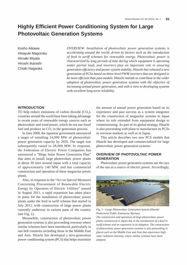
Hitachi Review Vol. 62 (2013), No. 1 65
Highly Efficient Power Conditioning System for Large Photovoltaic Generation Systems
Kosho Aikawa
Hisayuki Magoroku
Hiroaki Miyata
Hiroshi Ikarashi
Chiaki Nagaoka
OVERVIEW: Installation of photovoltaic power generation systems is accelerating around the world, driven by factors such as the introduction of feed in tariff schemes for renewable energy. Photovoltaic power is characterized by long periods of time during which equipment is operating under partial load, and inverters play an important role in ensuring generation efficiency and power system stability. Hitachi has released a new generation of PCSs based on three-level PWM inverters that are designed to be more efficient than past models. Hitachi intends to contribute to the wider adoption of photovoltaic power generation systems with the objective of increasing annual power generation, and with a view to developing systems with excellent long-term reliability.
INTRODUCTIONTO help reduce emissions of carbon dioxide (CO2), countries around the world have been taking advantage in recent years of renewable energy sources such as photovoltaic and wind power, which do not use fossil fuel and produce no CO2 in the generation process.
in June 2008, the Japanese government announced a target of installing 14,000 MW of photovoltaic power generation capacity by 2020. The target was subsequently raised to 28,000 MW. in response, the Federation of Electric Power Companies has announced a “Mega solar Power Generation Plan” that aims to install large photovoltaic power plants at about 30 sites around Japan with a total capacity of approximately 140 MW, and has commenced construction and operation of these megasolar power plants.
Also, in response to the “Act on special Measures Concerning Procurement of Renewable Electric Energy by Operators of Electric Utilities” passed in August 2011, a rapid expansion has taken place in plans for the installation of photovoltaic power plants under the feed in tariff scheme that started in July 2012, with construction of large power plants currently underway in various parts of the country (see Fig. 1).
Meanwhile, construction of photovoltaic power generation systems is also proceeding overseas where similar schemes have been introduced, particularly in sun belt countries including those in the Middle East and Asia. hitachi has developed a next-generation power conditioning system (PCs) that helps maximize
the amount of annual power generation based on its experience and past success as a system integrator for the construction of megasolar systems in Japan where its role extended from equipment design to commissioning. As part of its global strategy, hitachi is also proceeding with plans to manufacture its PCss in overseas markets as well as in Japan.
This article describes two new PCs models that hitachi has developed and commercialized for large photovoltaic power generation systems.
OVERVIEW OF PHOTOVOLTAIC POWER GENERATION
Photovoltaic power generation systems use the rays of the sun as a source of electric power. Accordingly,
Fig. 1—Large Photovoltaic Generation System (Ibaraki Prefectural Public Enterprise Bureau).The construction and operation of large photovoltaic power plants commenced in Japan due to the introduction of a feed in tariff scheme and an expansion in its adoption. The construction of photovoltaic power generation systems is also proceeding in places such as the Middle East and Asia that experience high solar radiation intensity, where similar schemes have been adopted.

Highly Efficient Power Conditioning System for Large Photovoltaic Generation Systems 66
the amount of power generated is strongly influenced by the weather conditions that determine how much sunlight gets through.
Solar Radiation Intensity and Power OutputThe power output of a photovoltaic panel is
normally rated based on a solar radiation intensity of 1 kW/m2 falling on a panel at a temperature of 25°C. Because the angle of incidence of sunlight varies depending on the season and the time of day, the power generated from a panel on a fixed platform typically starts to increase from dawn, peaks when the sun reaches its zenith for the day, and then decreases again toward sunset.
Accordingly, photovoltaic panels only generate their rated maximum output around noon and during that part of the year when sunlight is strong and the temperature comparatively low. Therefore, power plant equipment such as photovoltaic panels, PCss, and step-up transformers operate at partial loads of between 20% and 80% of their rated capacity for significant periods of time. This makes it essential that the equipment be able to generate power with high efficiency even under partial load.
Role of PCSA PCs is an inverter connected to the electric
power grid that converts the direct current (DC) from the photovoltaic panel into alternating current (AC) (see Fig. 2). A feature of photovoltaic panels is that the current they generate varies depending on factors such as the level of sunlight and the voltage across their terminals. Therefore, the output power (the product of the current and the voltage across their terminals) depends on these same factors. The PCs is equipped with a maximum power point tracking (MPPT) function that improves the efficiency of power generation by optimizing the voltage across the panel terminals to maximize the generated power based on the level of sunlight.
Large-capacity PCss for megasolar power generation systems also require functions for power system stabilization. Working through demonstrations and other projects run by the New Energy and industrial Technology Development Organization (NEDO), hitachi has already developed and implemented functions that include minimizing grid voltage fluctuations, maintaining operation during short-duration voltage drops, and suppression of harmonics.
FEATURES OF NEW TYPE OF PCShitachi already markets PCss in Japan and other
countries. The inverters in these PCss use two-level pulse width modulation (PWM) and achieve small size and high efficiency through features that include a transformer-less configuration and high output voltage (400 V). Responding to recent market growth, hitachi has now developed and commercialized a new type of PCs designed for even higher efficiency.
Use of Three-level PWM InverterConventionally, three-level PWM inverters
have only been used in applications that require the suppression of harmonics or a higher converter voltage, such as in railway rolling stock or large motor drives. however, with insulated-gate bipolar transistor (iGBT) modules for three-level inverters in the 600 to 1,200-V class having become commercially available in recent years, thereby allowing three-level inverters to be implemented without requiring a significant increase in the component count, hitachi has gone ahead with the commercialization of next-generation PCss that use this method to improve conversion efficiency further (see Fig. 3).
The anticipated benefits of using three-level PWM inverters include lower switching loss, the ability
Fig. 2—PCS for Photovoltaic Power Generation System.A PCS is an inverter connected to the electric power grid that converts the DC electric power generated by the photovoltaic panels to AC.
Solarradiationintensity
CurrentPower
Voltage
1,200 mm
Coolingair flow
Main circuitcable conduit
(DC) (AC)Main circuitcable conduit
Front view Right side view
1,90
0 m
mB
ase
50 m
m
1,000 mm
Photovoltaic panelcharacteristics
Photovoltaic panel
DC power DC power
AC power
PCS
GridGrid connection inverter
Chopper
Chopper
0
Operating points that maximize outputC
urre
nt, p
ower
Solarradiationintensity
Boost DC voltage while adjusting voltage across photovoltaic panel terminals to maximize power output.
Convert DC power to AC and connect to grid.
DC: direct current AC: alternating current PCs: power conditioning system
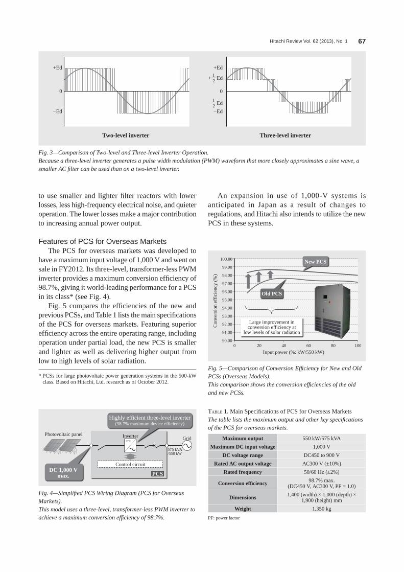
Hitachi Review Vol. 62 (2013), No. 1 67
to use smaller and lighter filter reactors with lower losses, less high-frequency electrical noise, and quieter operation. The lower losses make a major contribution to increasing annual power output.
Features of PCS for Overseas MarketsThe PCs for overseas markets was developed to
have a maximum input voltage of 1,000 V and went on sale in FY2012. its three-level, transformer-less PWM inverter provides a maximum conversion efficiency of 98.7%, giving it world-leading performance for a PCs in its class* (see Fig. 4).
Fig. 5 compares the efficiencies of the new and previous PCss, and Table 1 lists the main specifications of the PCs for overseas markets. Featuring superior efficiency across the entire operating range, including operation under partial load, the new PCs is smaller and lighter as well as delivering higher output from low to high levels of solar radiation.
An expansion in use of 1,000-V systems is anticipated in Japan as a result of changes to regulations, and hitachi also intends to utilize the new PCs in these systems.
+Ed
−Ed
Two-level inverter Three-level inverter
0
+Ed
−Ed
+ Ed21
− Ed21
0
Fig. 3—Comparison of Two-level and Three-level Inverter Operation.Because a three-level inverter generates a pulse width modulation (PWM) waveform that more closely approximates a sine wave, a smaller AC filter can be used than on a two-level inverter.
Photovoltaic panel Inverter
Control circuitDC 1,000 V
max.
Grid
Highly efficient three-level inverter(98.7% maximum device efficiency)
575 kVA/550 kW
PCS
Fig. 4—Simplified PCS Wiring Diagram (PCS for Overseas Markets).This model uses a three-level, transformer-less PWM inverter to achieve a maximum conversion efficiency of 98.7%.
* PCss for large photovoltaic power generation systems in the 500-kW class. Based on hitachi, Ltd. research as of October 2012.
Large improvement inconversion efficiency at
low levels of solar radiation
New PCS
Old PCS
100.00
0 20
Input power (%: kW/550 kW)40 60 80 100
Con
vers
ion
effi
cien
cy (
%)
99.00
98.00
97.00
96.00
95.00
94.00
93.00
92.00
91.00
90.00
Fig. 5—Comparison of Conversion Efficiency for New and Old PCSs (Overseas Models).This comparison shows the conversion efficiencies of the old and new PCSs.
Maximum output 550 kW/575 kVA
Maximum DC input voltage 1,000 V
DC voltage range DC450 to 900 V
Rated AC output voltage AC300 V (±10%)
Rated frequency 50/60 hz (±2%)
Conversion efficiency 98.7% max. (DC450 V, AC300 V, PF = 1.0)
Dimensions 1,400 (width) × 1,000 (depth) × 1,900 (height) mm
Weight 1,350 kg
TABLE 1. Main specifications of PCs for Overseas MarketsThe table lists the maximum output and other key specifications of the PCS for overseas markets.
PF: power factor

Highly Efficient Power Conditioning System for Large Photovoltaic Generation Systems 68
Features of PCS for Japanese MarketPCs for the Japanese market combines a
transformer-less, three-level PWM inverter with a step-up chopper input circuit that enables MPPT control to be performed over a wide range of voltages (DC230 V to 600 V). it features enhanced conversion efficiency in the DC400 V to 500 V range (see Fig. 6). The step-up chopper consists of two circuits, each of which has an input capacity of 250 kW and supports MPPT operation.
Fig. 7 compares the efficiencies of the new and previous PCss, and Table 2 lists the main specifications of the PCs for the Japanese Market.
This product range includes an outdoor package suitable for large photovoltaic power plants (see Fig. 8). The ability to deliver the outdoor package to the installation site with two PCss already fitted helps shorten installation time because it means that
on-site setup work can be performed efficiently. The outdoor package isolates the PCss from the external atmosphere and ensures that the PCss operate reliably by using multiple air conditioning units to perform efficient internal cooling.
CONCLUSIONSThis article has described two new PCs models that
hitachi has developed and commercialized for large photovoltaic power generation systems.
hitachi is developing a variety of renewable energy technologies based on its experience and past success in a wide range of fields, including power electronics and system control technology.
Regarding PCss for large photovoltaic power generation systems, hitachi has been involved in the development of PCss with high efficiency and large capacity from an early stage, including participation as a sub-contractor to NTT Facilities, inc. in the NEDO-sponsored “Verification of Grid stabilization with Large-scale PV Power Generation systems” project, and the PCs products described in this article represent the culmination of the work conducted to date.
Photovoltaicpanel
Highly efficient three-level inverter(98% maximum device efficiency)
Supports a wide range of DC voltages (MPPT control can be used
between 230 V and 600 V DC).
Inverter
Chopper
Chopper
PCS
525 kVA/500 kW
250 kW
250 kW
Grid
Control circuit
Fig. 6—Simplified PCS Wiring Diagram (PCS for the Japanese Market).This model can use MPPT control over a wide range of voltages and features improved efficiency between 400 V and 500 V DC.
MPPT: maximum power point tracking
Conversion efficiencyimproved over wide range
New PCS
Old PCS
100.00
0 20
Input power (%: kW/500 kW)40 60 80 100
Con
vers
ion
effi
cien
cy (
%)
99.00
98.00
97.00
96.00
95.00
94.00
93.00
92.00
91.00
90.00
Fig. 7—Comparison of Conversion Efficiency for New and Old PCSs (Japan Models).This comparison shows the conversion efficiencies of the old and new PCSs.
Maximum output 500 kW/525 kVA
Maximum DC input voltage 660 V
DC voltage range DC230 to 600 V
Rated AC output voltage AC420 V/440 V (±10%)
Rated frequency 50/60 hz (±2%)
Conversion efficiency 98% max. (DC500 V, AC420 V, PF = 1.0)
Dimensions 1,200 (width) × 1,000 (depth) × 1,900 (height) mm
Weight 1,600 kg
TABLE 2. Main specifications of PCs for the Japanese MarketThe table lists the maximum output and other key specifications of the PCS for the Japanese market.
Fig. 8—PCS Outdoor Package.The product range includes an outdoor package suitable for large photovoltaic power plants.
Hitachi Review Vol. 62 (2013), No. 1 69
to draw on the technologies and experience that it has built up in grid interconnection and renewable energy to work toward the wider adoption of systems with excellent long-term reliability. Hitachi also intends to contribute to the spread of smart grids through highly flexible systems that combine photovoltaic power generation systems with microgrids, energy storage systems, and other technologies.
In addition to conversion efficiency, long-term system reliability has also become an extremely important consideration for the large photovoltaic power generation systems that are anticipated to become more widely used in the future. This is to ensure that electric power can be generated reliably over long periods of time in combination with a diverse variety of different photovoltaic panels. Hitachi intends
Hisayuki MagorokuJoined Hitachi, Ltd. in 2010, and now works at the Photovoltaic Power Generation Business Department, Generator Systems Division, Power & Industrial Systems Division, Power Systems Company. He is currently engaged in business development for large photovoltaic generation systems for Japan and other countries.
Hiroshi IkarashiJoined Hitachi, Ltd. in 1997, and now works at the Power Electronics Design Department, Infrastructure Systems Business Management Division, Infrastructure Systems Company. He is currently engaged in the design of PCSs for large photovoltaic generation systems.
Kosho AikawaJoined Hitachi, Ltd. in 1989, and now works at the Photovoltaic Power Generation Business Department, Generator Systems Division, Power & Industrial Systems Division, Power Systems Company. He is currently engaged in business development for large photovoltaic generation systems for Japan and other countries.
Hiroaki MiyataJoined Hitachi, Ltd. in 1994, and now works at the Strategy Planning & Development Office, Infrastructure Systems Company. He is currently engaged in the design and development of power electronics products including grid interconnection inverters and large UPSs at Hitachi Hi-Rel Power Electronics Pvt. Ltd. Mr. Miyata is a member of The Institute of Electrical Engineers of Japan (IEEJ).
Chiaki NagaokaJoined Hitachi, Ltd. in 1998, and now works at the Sales and Marketing Department 3, Overseas Business Development Division, Infrastructure Systems General Sales Division. He is currently engaged in overseas sales of PCSs for large photovoltaic generation systems.
ABOUT THE AUTHORS

Hitachi Review Vol. 62 (2013), No. 1 70
Hitachi’s Involvement in Use of Nuclear Power Generation to Resolve Energy Issues
Masahiko Nakane
Takashi Masui
Masahiro Hamamoto
Mizuki Igarashi
OVERVIEW: Despite significant changes in the status of nuclear power generation around the world since the accident at the Fukushima Daiichi Nuclear Power Station of Tokyo Electric Power Co., Inc., considerations such as global environmental problems and energy security mean that many countries still have plans to introduce nuclear power under study or in progress. Regarding the adoption of nuclear power generation by countries that are pursuing the peaceful use of nuclear energy, Hitachi is collaborating with its BWR technology partner, GE-Hitachi Nuclear Energy Americas LLC, to make further safety improvements and to work toward resolving global energy issues.
INTRODUCTIONWhEN the future of nuclear power is considered, factors such as the shale gas (unconventional natural gas) revolution in the UsA and changes in policy by national governments after the accident at the Fukushima Daiichi Nuclear Power station mean that circumstances have changed significantly from the “nuclear renaissance” that people spoke of only a few years ago. Nevertheless, highly economic nuclear power has a contribution to make to society and still retains an important role as a way of overcoming global challenges such as global environmental problems and energy security. Keeping in mind the opportunity to enhance safety further by learning from the accident, those countries that have a policy for utilizing nuclear power are proceeding with plans for new nuclear power plants, and are pressing ahead with their implementation. Meanwhile, human resource development is a critical issue for those countries with plans to introduce nuclear power generation for the first time, and there is a need for cooperation through international aid.
This article describes hitachi’s involvement in the nuclear power business in major markets, focusing in particular on the activities of hitachi-GE Nuclear Energy, Ltd. (hGNE).
ACTIVITIES IN REPUBLIC OF LITHUANIAThe Republic of Lithuania operated two nuclear
reactors at the ignalina Nuclear Power Plant built when the nation was still part of the soviet Union, and was an exporter of electricity with nuclear power accounting for approximately 80% of its total power
generation. however, because the ignalina power plant used the same light-water-cooled, graphite-moderated reactors as the Chernobyl Nuclear Power Plant, Unit 1 was shutdown in late 2004 and Unit 2 in late 2009 as part of the terms of the nation’s accession to the European Union (EU), and the reactors are
Fig. 1—Planned Construction Site of Visaginas Nuclear Power Plant.The Visaginas Nuclear Power Plant is to be constructed on a site adjacent to the existing Ignalina Nuclear Power Plant (currently being decommissioned).
Planned site for construction ofVisaginas Nuclear Power Plant
0 30 60 km
Vilnius
Republic of Lithuania
Planned site forconstruction of Visaginas
Nuclear Power Plant
Ignalina Nuclear Power Plant• Light-water-cooled, graphite-moderated reactors• Reactors shut down in 2004 and 2009,
now being decommissioned

Hitachi Review Vol. 62 (2013), No. 1 71
now being decommissioned. As a result, Lithuania is now a net electricity importer. When imports of natural gas are included, the nation is dependent on the Russian Federation for approximately 80% of its energy consumption.
To overcome this problem of energy security, the three Baltic states, the Republic of Lithuania, the Republic of Estonia, and the Republic of Latvia, together with the Republic of Poland, reached an agreement in 2006 to proceed with the construction of a nuclear power plant. Visagino Atominė Elektrinė (VAE) was established in 2008 to undertake the construction of the Visaginas Nuclear Power Plant on a site adjacent to the existing ignalina Nuclear Power Plant (see Fig. 1).
hitachi, Ltd. and Westinghouse Electric Company LLC entered bids in the May 2011 tender process for selecting a strategic investor (si) to partner in the Visaginas Nuclear Power Plant construction project. hitachi, Ltd. was subsequently appointed si in July 2011 and given preferred bidder status for negotiating a formal order.
in addition to hitachi’s extensive construction experience in Japan, one of the factors behind hitachi gaining preferred bidder status was the fact that it was quickly able to produce a proposal that included finance and was satisfactory to the customer by drawing on its experience and know-how in overseas engineering, procurement, and construction (EPC) projects. These have included work in the United Arab Emirates. it is also likely that this customer, who values long-term partnerships, has a high regard for hitachi’s stance of frank dealing, including in the period after the Great East Japan Earthquake.
Now that preferred bidder status has been acquired, hitachi will be undertaking an exclusive process of negotiating and coordinating requirements with the aim of finalizing the concession agreement (CA), EPC contracts, and other arrangements with VAE, the local partners (the national electric power companies of Estonia and Latvia), and the project company (PCO) financed and set up by the si.
hitachi’s proposal for the Visaginas Nuclear Power Plant is a 1,350-MWe-class advanced boiling water reactor (ABWR) with enhanced safety incorporating countermeasures to the accident at Fukushima Daiichi Nuclear Power station (see Fig. 2). hitachi then worked with VAE to finalize the technical aspects of the project’s basic requirements, including the schedule and allocation of work, the checks and modifications required for the approvals process,
including the approvals agency, and the design conditions, including the geology and surrounding environment at the construction site. This phase completed in December 2011.
in June, the Parliament of the Republic of Lithuania passed a number of laws associated with the project by majority vote, including the CA. The laws were then signed by the President and put into effect. Also in June, Lithuania issued a request to the European Commission under the terms of the Euratom Treaty to which the Commission responded by issuing a statement of support for the project, indicating that the environment for the project to proceed is in place.
Following a general election and referendum in October 2012, the Lithuanian government has indicated that it will formulate a general energy policy by May 2013 and submit the laws required to implement this policy to the Parliament of the Republic of Lithuania. VAE, the local partners, and hitachi, Ltd. in its role as the si, intend to continue discussions on how to proceed with the project.
in addition to providing energy security for Lithuania, this project is seen as having an important role in the energy strategy of the three Baltic states, and it also plays a part in the integration with European electric power markets through the Baltic Energy Market interconnection Plan (BEMiP).
ACTIVITIES IN ASIAAsia is experiencing strong economic growth and
many Asian nations have adopted the introduction of
Fig. 2—Three-dimensional Image of Visaginas Nuclear Power Plant.Hitachi has proposed a 1,350-MWe-class advanced boiling water reactor (ABWR) with enhanced safety incorporating countermeasures to the accident at Fukushima Daiichi Nuclear Power Station. The existing Ignalina Nuclear Power Plant (currently being decommissioned) is visible in the rear.

Hitachi’s Involvement in Use of Nuclear Power Generation to Resolve Energy Issues 72
nuclear power generation by early 2020 as a national policy, with objectives that include satisfying the increase in demand for electric power brought about by this growth and reducing reliance on fossil fuels. While progress on plans for achieving this varies between nations, and some have decided to review their plans in light of the accident at Fukushima, recognition of the need for nuclear power generation in the medium to long term remains very high.
Given these circumstances, Japan and hitachi are cooperating in a variety of ways with the introduction of nuclear power generation in neighboring Asian nations. Japan is a leader in the field of nuclear power, and hitachi has been developing technology for nuclear power generation for many years and has built a large number of plants. Rather than just supplying nuclear power generation equipment that is safer and has excellent economics, this also represents a valuable opportunity to contribute to initiatives such as international security, the promotion of international collaboration, and cooperation on human resource development.
Socialist Republic of Viet NamhGNE has been supporting the adoption of
nuclear power generation by the socialist Republic of Viet Nam for many years. in October 2010, the governments of Japan and Vietnam agreed on Japan being made a partner in the construction at the second nuclear power plant site in Ninh Thuan Province. international Nuclear Energy Development of Japan Co., Ltd. (JiNED) was established by Japan to coordinate nuclear power generation exports. in september 2011, JiNED signed a memorandum of understanding with Vietnam Electricity holding Company (EVN) to establish the collaborative
framework for the introduction of nuclear power generation to Vietnam with the Japanese government and private companies working together. To meet the requirements of Vietnam, hGNE has proposed ABWR technology in the form of the only third-generation-plus reactor in the world to be in actual operation. Cooperation on human resource development is also taking place, with nuclear power scholarships and the running of satellite courses at the hanoi University of science and Technology (hUsT), and the Electric Power University (EPU) in collaboration with the Tokyo institute of Technology (see Fig. 3).
MalaysiaJapan and Malaysia signed a bilateral cooperation
agreement in 2010 aimed at establishing the basis for Malaysia’s nuclear power generation plans. Following on from this agreement, a nuclear technology seminar was hosted later the same year by the Malaysian Nuclear Agency, and this was followed up with ongoing activities such as a presentation on safety improvement to local interested parties, including the Malaysia Nuclear Power Corporation (see Fig. 4). Meanwhile, hitachi is taking advantage of the work done with Vietnam to promote cooperation on human resource development in Asia in the field of nuclear power, with programs being run for that country to be extended to Malaysia from 2013. This will involve the invitation of Malaysian students and researchers to Japan under a hitachi nuclear power scholarship program and the hosting of satellite courses in collaboration with the Tokyo institute of Technology.
Fig. 3—Image of Nuclear Power Plant for Socialist Republic of Viet Nam.The main building and emergency equipment are located 15 m or more above sea level in case of tsunamis.
Fig. 4—Scene from First Malaysian Nuclear Agency ABWR Seminar.A seminar on ABWR technology in December 2010 was hosted by the Malaysian Nuclear Agency and attended by more than 120 people, including many Malaysian university academics.

Hitachi Review Vol. 62 (2013), No. 1 73
Kingdom of ThailandWith objectives that include meeting growing
demand for electric power and reducing dependence on natural gas, the Kingdom of Thailand is planning to introduce nuclear power generation from the early 2020s. since 2008, hGNE has been inviting interested parties, including the Electricity Generating Authority of Thailand (EGAT), to visit its factories and nuclear power plants in Japan, and also running a vigorous program of local seminars and other technology presentations (see Fig. 5). A feasibility study conducted in 2009 and 2010 selected the ABWR proposed by hGNE as one of the preferred reactor designs. Cooperation on achieving public acceptance is also ongoing, along with investigations into establishing the important underpinnings for the plans for Thailand’s first nuclear power plant, including assistance with arranging an inspection of Japanese nuclear power facilities by relevant people from the Thai government in response to a request from EGAT to participate in public relations.
ACTIVITIES IN UKPlans for New Nuclear Power Plants
The UK shifted to a policy of favoring nuclear power during the period when Gordon Brown was prime minister, with the publication by the government of an energy white paper in 2008 that included a policy of pursuing nuclear power. This was in response to the fact that, with the exception of one pressurized water reactor (PWR), all 16 nuclear power plants currently in operation in the UK are due to be shut down by
2023. Accordingly, the government selected eight sites for new plants in 2011 and awarded construction of new plants to EDF Energy, the national electric power company of France, and the horizon Nuclear Power Limited consortium, which was owned by two German electric power companies, RWE npower plc and E.ON UK plc. The two organizations are proceeding with plans for construction, at two sites adjacent to the existing hinkley Point and sizewell nuclear power stations in the case of EDF Energy, and at two sites adjacent to the existing Wylfa and Oldbury nuclear power stations in the case of horizon Nuclear Power. since then, the owners of horizon Nuclear Power decided for domestic reasons to sell their stakes to hitachi, Ltd., with the sale completed in November 2012. Meanwhile, NuGeneration Limited, a joint venture between the French electric power company GDF suez s.A. and spanish electric power company iberdrola, s.A., owns the Moorside site. For the remaining three sites, it is understood that they are to be sold to third parties by the current owner, EDF Energy, in accordance with the UK government’s strategy, with work on new nuclear power plant construction to proceed within the UK.
Electricity Market ReformThe UK government recognizes nuclear power as
a low-carbon energy source and is proceeding with laws to establish a Feed-in Tariff with Contract for Difference scheme for low-carbon electric power as part of its electricity market reform policies. The Energy Bill containing measures for electricity market reform was introduced to parliament in November 2012. if passed, it is anticipated that this bill will encourage investment by reducing the risks for investors in nuclear power.
Purchase by Hitachi, Ltd. of Horizon Nuclear Power Limited
By purchasing horizon Nuclear Power Limited, hitachi has acquired two sites for plant construction, at Wylfa and Oldbury. horizon Nuclear Power Limited has plans to construct two or three 1,300-MW-class nuclear power plants at each of these sites. The target is for the first plant to commence operation in the early 2020s.
To prepare for this project, hGNE initiated discussions with the UK Office for Nuclear Regulation in December 2012 with the aim of obtaining approval for the ABWR through the UK’s Generic Design Assessment (GDA) process. hitachi has also
Fig. 5—Construction Site Visit.To promote understanding of nuclear power generation, relevant people from the Thai government and EGAT were shown construction technology and work in progress at the latest ABWR plant.

Hitachi’s Involvement in Use of Nuclear Power Generation to Resolve Energy Issues 74
As the two companies have based their business operations around boiling water reactor (BWR) technology, a variety of opportunities exist for exploiting synergies beyond those already quoted. Examples include utilization of the naturally circulated reactor technology from the Economic and simplified Boiling Water Reactor (EsBWR) in the development of small BWRs, sharing of design resources, and encouraging the shared use of test facilities.
CONCLUSIONSThis article has described hitachi’s involvement in
the nuclear power business in major markets, focusing in particular on the activities of hitachi-GE Nuclear Energy, Ltd.
hGNE and GEh are pursuing a common strategy for their nuclear power businesses. By adapting to changing global markets and exploiting synergies to boost competitiveness, they intend to contribute to overcoming international challenges, such as global environmental problems and energy security.
embarked on consultations with relevant organizations to set up a UK supply chain, and plans to form an EPC consortium in the near future.
COLLABORATIVE ARRANGEMENTS WITH GEH
hGNE and GEh, the joint-venture nuclear power companies established by hitachi, Ltd. and General Electric Company (GE) in 2007, have been sharing resources in their nuclear power business activities. They have also strengthened their collaborative arrangements on a range of projects, with the aims of expanding their businesses in the global market and boosting competitiveness by taking advantage of synergies. in the Lithuania contract being sought by hGNE, for example, hitachi is utilizing GEh resources such as their approvals and licensing engineering. Elsewhere, hGNE and GEh are adopting common strategies to building a marketing organization that can target specific projects in ways that draw on the respective strengths of each company.
Takashi MasuiJoined Hitachi, Ltd. in 1987, and now works at the Business Development Department, Hitachi-GE Nuclear Energy, Ltd. He is currently engaged in development work for overseas nuclear power business.
Mizuki IgarashiJoined Hitachi, Ltd. in 2002, and now works at the Business Development Department, Hitachi-GE Nuclear Energy, Ltd. She is currently engaged in development work for overseas nuclear power business.
Masahiko NakaneJoined Hitachi, Ltd. in 1981, and now works at the UK Project Department. He is currently engaged in development work for overseas nuclear power business.
Masahiro HamamotoJoined Hitachi, Ltd. in 1979, and now works at the Business Development Department, Hitachi-GE Nuclear Energy, Ltd. He is currently engaged in sales of nuclear power generation equipment, primarily for Asian markets. Mr. Hamamoto is a member of the Atomic Energy Society of Japan.
ABOUT THE AUTHORS
Hitachi Review Vol. 62 (2013), No. 1 75
Lessons Learned from Fukushima Daiichi Nuclear Power Station Accident and Consequent Safety Improvements
Masayoshi Matsuura
Kohei Hisamochi
Shinichiro Sato
Kumiaki Moriya
OVERVIEW: In March 2011, an accident occurred at the Fukushima Daiichi Nuclear Power Station of Tokyo Electric Power Co., Inc. in Japan. The accident came at a time when international demand for the construction of nuclear power plants appeared to be growing against a background of concerns about the security of fossil fuel supplies, which include oil and coal, and because of nuclear power’s effectiveness as a means for countering global warming. While reactions to the accident in nuclear power markets outside Japan varied from country to country, many countries in regions such as Asia and the Middle East, where there are plans to construct new plants, have announced their intention to continue with policies that promote nuclear power, with the provision that necessary countermeasures will be adopted based on a close investigation of what happened at Fukushima. Hitachi intends to contribute to safer and more reliable plant operation and construction by incorporating the lessons learned from the accident at the Fukushima Daiichi Nuclear Power Station into its nearly 40 years of experience in the construction of nuclear power plants so that it can supply ABWRs with even higher levels of safety, and also to consider how these lessons can be applied in existing plants.
INTRODUCTIONThE Great East Japan Earthquake that struck in March 2011 and the resulting accident at Fukushima Daiichi Nuclear Power station of Tokyo Electric Power Co., inc. brought enormous damage to Japan.
Fully recognizing the seriousness of this accident, hitachi has been cooperating wholeheartedly in the recovery and reconstruction of the affected regions and Fukushima Daiichi Nuclear Power station, while also working to restore faith in nuclear power generation.
Over the nearly 40 years since it participated in the construction of Japan’s first boiling water reactor (BWR), hitachi has been striving to improve their reliability, safety, and economics. During that time, hitachi has been involved in the construction of more than 20 such reactors. hitachi has also been involved in the joint development of the advanced boiling water reactor (ABWR) in collaboration with power companies that operate BWRs, General Electric Company, and Toshiba Corporation. The ABWR is a generation iii+ reactor design (as defined by the U.s. Department of Energy), and is the only reactor of this generation to be in actual use. hitachi was involved in the construction of all four ABWRs currently in commercial operation and is responsible for major components in ABWRs currently being built. Also, in July 2011, hitachi was selected as a strategic investor
(si) in the Visaginas Nuclear Power Plant Project in the Republic of Lithuania, and is currently proposing an ABWR design with enhanced safety, including measures adopted in response to the accident at Fukushima Daiichi Nuclear Power station.
This article gives an overview of the basic strategy for enhancements to safety based on the lessons learned from the accident at Fukushima Daiichi Nuclear Power station, summarizes the specific equipment countermeasures applicable to the ABWR, and describes policies for the deployment of safety enhancements at existing plants in Japan.
LESSONS LEARNED FROM FUKUSHIMA DAIICHI NUCLEAR POWER STATION ACCIDENT
This section reviews the situation at the Fukushima Daiichi Nuclear Power station following the accident and describes the lessons learned.
Situation at Plant after Fukushima Daiichi Nuclear Power Station Accident
Responding to seismic acceleration, Fukushima Daiichi Nuclear Power station went into automatic shutdown (a large scram) at approximately 2:46 PM on March 11, 2011. With external power having been lost due to the earthquake, the backup diesel generators

Lessons Learned from Fukushima Daiichi Nuclear Power Station Accident and Consequent Safety Improvements 76
(DGs) started automatically to provide emergency power. subsequently, at approximately 3:35 PM, the power station was struck by the tsunami, resulting in the inundation of water supply equipment, including the emergency seawater system, and the flooding of the yards around the buildings. Water also entered the buildings causing some basement equipment to become submerged.
This unavailability of the emergency seawater system left the plant without any way of shedding heat, a situation called “loss of ultimate heat sink” (LUhs). The loss of the emergency seawater system also prevented the backup diesel generators from running and caused a “station blackout” (sBO) in which all alternating current (AC) power was lost. The inundation of the building also left some switchboards out of action, including a
loss of direct current (DC) power due to the resulting unavailability of DC power infrastructure. This loss of control power and plant status monitoring functions greatly impeded the plant’s management of the accident.
Fig. 1 shows the sequence of events during the Fukushima Daiichi Nuclear Power station accident (using the example of Unit 1), and their relationships to the lessons learned.
Lessons from Accident(2)
This section describes seven lessons learned from an analysis of the sequence of events during the accident at the Fukushima Daiichi Nuclear Power station, using Unit 1 as an example. Although the sequences of events at Units 2 and 3 were different, the lessons are believed to be the same.
Fig. 1—Sequence of Events and Lessons Learned from Effectiveness of Current AM Equipment(1).The figure shows how the lessons learned relate to the functional status of the current AM equipment during the sequence of events at the Fukushima Daiichi Nuclear Power Station (using the example of Unit 1).
Earthquake scram
Tsunami strikes
Water level recedes.
Core degradation starts (analysis).
Fire appliances startsupplying fresh water.
Damage to RPV (analysis)
PCV overheating leakage (analysis)
Work starts on PCV (W/W) vent.
Work completes on PCV (W/W) vent.
Building explosion
Low pressure in RPV,high pressure in PCV
Sequence of events Effectiveness of current AM practices and lessons learned
Loss of all AC power (SBO) (unable to redirect power supply)
Lesson 1: Relocation of switchboards and other important equipment to better sites, utilize portable equipment, and ensure access
Lesson 2: Configuration and deployment of isolation valvesLesson 3: Provision of backup DC power supply for important equipmentLesson 4: Instrument reliability and credibility, and measures for
dealing with this situation
Lesson 5: Provision of wider range of water injection and cooling systemsLesson 6: Accessibility, ease-of-use, and effectiveness of AM equipmentLesson 7: Provision of alternative means for protecting containment vessel
Lesson 6: Accessibility, ease-of-use, and effectiveness of AM equipment
Failure of high-pressure cooling of core and inability to release pressure in reactor
Delay in injection of reactor water (alternative water supply)
Delay in PCV venting (reinforced pressure vent)
3/11 14:46
Loss of external power → Automatic startup of backup DGsReactor isolation → Automatic startup of ICs, intermittent manual operation
• Flooding of backup DGs and switchboards → Loss of all AC power (motors cannot run)
• Loss of seawater system → loss of ultimate heat sink (cold shutdown function)
• Loss of DC power due to flooding of electrical rooms (flooding of switchboards, loss of instrumentation and control equipment)
→ Loss of IC and HPCI functions, loss of remote SRV operation
3/11 15:35
3/11 18:30
3/12 2:30
3/12 5:46
3/12 7:20
3/12 8:00
3/12 9:30
3/12 14:30
3/12 15:36
• Although AM practices included a facility for diverting low-voltage AC power from Unit 2, this could not be used due to the tsunami.
• Although a power supply vehicle arrived at around 11 PM on March 11, flooding of all switchboards caused a long delay in restoration of electric power.
• The loss of DC power due to the tsunami also disabled high-pressure cooling because instrumentation and high-pressure systems (IC and HPCI) required DC power. → Inadequate time for lining up low-pressure water injection and reducing pressure
• The difficulty of lining up valves due to loss of power, low air pressure, flooding, and high radiation levels meant this work could not be performed in time (venting took about 6 hours to achieve).
• Although steps were taken to use alternative methods for injecting water after loss of pressure due to core damage, all existing water injection systems were out of action.
• Supply from fire appliances, access to building, and connection of firefighting lines proved difficult, and this delayed use of fire appliances to supply water from firefighting lines.
• Unavailability of water supplies made continuous water injection difficult → Water injection required fire appliances to make round trips between firefighting water reservoir and FP water pipe inlet (1 m3 per trip).
• As a result of extended periods without water injection, the temperature of the PCV rose leading to leaks from gaskets.
AM: accident management AC: alternating current sBO: station blackout DGs: diesel generators iCs: isolation condensers DC: direct current hPCi: high-pressure coolant injection system sRV: safety relief valve RPV: reactor pressure vessel PCV: primary containment vessel FP: fire protection W/W: wet well

Hitachi Review Vol. 62 (2013), No. 1 77
Lesson 1: Relocation of switchboards and other important equipment to better sites, utilize portable equipment, and ensure access
Waterproofing important equipment and installing it at as elevated a location as possible is an effective countermeasure against tsunamis. however, given that the large impact force of water and the presence of air inlets and outlets make it difficult to provide full protection, provide attachments for the emergency connection of portable equipment and have heavy machinery available for establishing access routes.Lesson 2: Configuration and deployment of isolation valves
it was reported that isolation valves could not be opened during the accident. While keeping isolation as the top priority, provide ways of opening the most important isolation valves remotely or manually (by locating isolation valves outside the containment vessel and providing backups including for electric power and pneumatics).Lesson 3: Provision of backup DC power supply for important equipment
Determining the status of plant was made difficult by the loss of instrumentation functions due to the lack of a DC power supply, there was insufficient time to line up the low-pressure water injection system due to the loss of high-pressure functions [isolation condenser (iC) and high-pressure coolant injection system (hPCi)] that require a DC power supply, and reducing pressure via the safety relief valves was delayed. Accordingly, provide portable or backup DC power supplies for this important equipment.Lesson 4: Instrument reliability and credibility, and measures for dealing with this situation
For those plant monitoring items that are critical to accident management (AM), review the environmental conditions for instruments (considering the harsh conditions that occur during an accident), provide alternative means for verifying the credibility of instrument readings, and provide measures for dealing with the situation when the plant status cannot be monitored due to lack of faith in these readings.Lesson 5: Provision of wider range of water injection and cooling systems
There is a need for greater diversity in the ways of dealing with a loss of functionality in excess of the design assumptions (including the provision of a long-term water source), including with regard to the response and assistance from off-plant. in addition to providing greater protection through measures such as improving the water tightness of key on-site equipment
and building layout, there is a need to ensure the flexibility to deal with a wide range of scenarios though greater diversity, including portable equipment.Lesson 6: Accessibility, ease‑of‑use, and effectiveness of AM equipment
in response to problems such as the valves required to operate AM equipment being difficult to approach because they were located close to the containment vessel, and system line up being delayed by the difficulty of connecting external water supply equipment, make improvements to the accessibility, ease-of-use, and other practical aspects of AM equipment.Lesson 7: Provision of alternative means for protecting containment vessel
it is possible that the interior of the containment vessel overheated due to insufficient core cooling, causing degradation of non-metallic components and the potential release of radioactive material. Accordingly, while keeping core cooling as the top priority, there is a need to protect the containment vessel by cooling it on the inside and by providing cooling from outside the containment vessel.
BASIC STRATEGY FOR SAFETY MEASURESA review of experience from the accident at
Fukushima Daiichi Nuclear Power station and the lessons learned indicates that there is a need to consider the potential for site-wide damage that exceeds equipment operating conditions as a result of wide-scale external events such as earthquakes and tsunamis. This means that flexible equipment is important for dealing with situations that exceed assumptions, while also reviewing protective equipment based on specified design standards, and there is a need to consider factors such as access to ensure the practicality of this equipment. The following section describes the basic strategy for safety measures based on the above considerations.
The first is to protect important safety equipment from design loads caused by external events. Examples include embankments, measures for making buildings watertight, and relocation of equipment for dealing with a complete loss of AC power.
The second is the use of portable equipment in the event that the protection for safety equipment fails, and the preparation of flexible responses (responses to external events that exceed design conditions). improving the durability of the containment vessel with respect to leaks of radioactive material is also important.
The third is to provide measures based on the use of flexible and portable equipment and to make

Lessons Learned from Fukushima Daiichi Nuclear Power Station Accident and Consequent Safety Improvements 78
response procedures as simple as possible to ensure that coordination can proceed smoothly in the event of a major external event leading to major damage across the entire site and a need for off-site assistance.
OVERVIEW OF SAFETY EQUIPMENTOverview of ABWR Safety Equipment
Nuclear power plants are built on the principle of defense in depth with designs that ensure safety through redundancy and diverse methods. Design of safety equipment establishes design conditions with enough of a safety margin to deal with a wide range of different accident scenarios, and then designs equipment that can function reliably under these conditions. in addition, to reduce risk and deal with events that fall outside the accident scenarios considered in the design, AM equipment is provided to manage operations such as the use of equipment other than safety equipment to inject water into the reactor or remove the heat generated in the reactor. Fig. 2 shows stochastic assessments of the safety with respect to on-site accidents of typical light water reactors and third-generation reactors, including the ABWR. The graph shows the ABWR as having the world’s highest level of safety.
BWRs have a simple direct-cycle configuration in which the generated steam is supplied to the turbine directly. The ABWR, which was developed primarily in Japan and the UsA, represents the culmination of this type of reactor. This use of a direct-cycle
configuration allows highly efficient generation of electric power at a low operating pressure. specifically, the operating pressure of the reactor is less than half that of a pressurized water reactor (PWR), another type of light water reactor. The features of the BWR power generation system are utilized in the design of the safety equipment. That is, because the BWR uses direct-cycle operation at low pressure, it is easy to inject water directly into the reactor, and therefore the basic approach to achieving safety is to provide a number of different alternative methods for water injection.
The section below describes specific equipment-related responses. Based on the basic strategy for safety measures described above, these responses are built on safety policies that take advantage of the features of the BWR. in this case, the explanation focuses on measures that relate to the second of the basic strategies, which affects power plant equipment.(1) Because of the likelihood of confusion in the initial response to major external events, depending on the level of damage, it was decided to make available portable equipment as a way of providing more options for injecting water into the core. This is a simple measure that takes advantage of the features of BWRs. Because this is a simple strategy, it should also be an effective way of cooperating with off-site assistance teams during times of confusion, as described for the third of the basic strategies for safety measures.(2) Connections from the outside and on-site operations performed in close proximity are important considerations when using portable equipment. Accordingly, the installation of a number of external connection points at different locations was considered to ensure flexibility.(3) in addition to adding alternative ways to inject water into the containment vessel, a facility for injecting water to the top head of the containment vessel was fitted to improve the durability of the vessel’s non-metallic components.(4) Also under study in addition to the above measures is the concept of a backup building equipped with an alternative power supply and a reactor water injection function for use in events that are bigger than expected. The concept involves a facility, located separately from the reactor building, that is kept sealed off during routine operation and only opened at times of emergency so that the facilities it provides will be able to function during events that are bigger than expected. Locating the in-place water injection equipment away from the reactor building allows water injection to be performed quickly. it should also be useful for functions such as providing
Fig. 2—Comparative Safety Assessments of ABWR and Other Light Water Reactors from Around the World.The graph shows stochastic assessments of safety with respect to on-site accidents of example light water reactors (BWRs and PWRs) and of ABWRs and other third-generation reactors.
1.0E-07
1.0E-06
1.0E-05
1.0E-04
1.0E-03
Sequoyah (USA): 1,100-MWe-class PWRSurry (USA): 800-MWe-class PWR
Peach Bottom (USA): 1,100-MWe-class BWRGrand Gulf (USA): 800-MWe-class BWR
Generation III+
Sequoyah(PWR)
Surry(PWR)
PeachBottom(BWR)
GrandGulf
(BWR)
APWR EPR ABWR
Source: NUREG-1150, DCD, http://www.nrc.gov
Freq
uenc
y of
cor
e da
mag
e (i
ncid
ents
/rea
ctor
-yea
r)
PWR: pressurized water reactor BWR: boiling water reactor APWR: advanced PWR EPR: European PWR ABWR: advanced BWR

Hitachi Review Vol. 62 (2013), No. 1 79
Strategy for Deployment of Safety Measures to Existing Plants in Japan
in July 2011, the Nuclear and industrial safety Agency instructed electric power companies to
a frontline base during emergencies or a storage facility for AM spare parts and other material. Fig. 3 shows an outline of this facility and Fig. 4 shows an overview of the ABWR safety equipment.
Gas turbine generatoror air-cooled DG
Hazard protection domeCulvert for pipes andcable access to R/B
Emergency control panel(equivalent to RSS)
Control room forcommunicationswith national andlocal government
Batteries
Portablebatteries
Mobile heat removal system(installed on a trailer)
Air inlet and outlet(fully sealed duringnormal operation)
Emergencywater supply
Electricaldistribution board
Power supplyvehicle
Portable pump
Air fin cooler forcooling equipment
inside backup building
Low-pressure watersupply (FLS) pump
Fig. 3—Sketch of Backup Building and Concept behind Alternative Power Supply and Reactor Water Injection Function.Hitachi has developed the concept of a backup building to provide power, portable equipment, and other resources, maintaining equipment functions in case of large external hazards so that water can be injected into the core quickly from a separately located building.
FLs: flooder system R/B: reactor building Rss: remote shutdown system
B/B
Portablebatteries for SRV
Alternative ACpower supply
(air-cooled DG)
Portable pump
Core waterinjection system
Water supply
Improvepressurereduction.
: New equipment
R/B
SFP replenishmentwater
PCV head cooling
PCV
SFP
RPV
PCV cooling
Corecooling
W/W
Suppressionpool
Improvewaterinjection.
Waterinlets
Portable heatremoval system
Maintain cooling of spent fuel cooling pool.
Prevent damage to PCV due to overheating.
Maintain power supply.
• Provide portable and backup DC power supplies to supply the important DC power for initial action and plant status monitoring.
• Provide a range of other power supplies (GTGs and air-cooled DGs) in addition to the backup power supply (DG).
• Locate buildings and plant where they will protect equipment and switchboards from external events such as a large earthquake or tsunami.
Maintain water injection systemand ultimate heat removal function.
• Provide a wider range of alternative water injection functions and enhance mobility by providing portable pumps.
• Provide a wider range of heat sinks such as portable heat removal systems or air-cooled heat removal systems.
• Maintain functions even if major external events occur.• Provide prompt core water injection, power supplies, and
portable equipment from a separately located building.
B/B
• Provide a wider range of functions for replenishing water in the pools and make AM operation easier by fitting external water supply inlets.
• Provide a wider range of functions for injecting water into the containment vessel.
• Use containment vessel top head cooling to prevent overheating damage.
Fig. 4—Overview of ABWR Safety Equipment.Based on experience from the accident at Fukushima Daiichi Nuclear Power Station and the lessons learned, important safety equipment is protected from the impact of wide-scale external events such as earthquakes and tsunamis, and safety equipment is built that allows flexible measures to be taken, using portable equipment for example, in the event that this protection fails.
GTG: gas turbine generator sFP: spent fuel pool B/B: backup building

Lessons Learned from Fukushima Daiichi Nuclear Power Station Accident and Consequent Safety Improvements 80
conduct stress tests to comprehensively assess the safety of existing nuclear power facilities in the light of the accident at Fukushima Daiichi Nuclear Power station. hitachi’s involvement included work on improving the water tightness of pipe entry locations and the earthquake resistance of firefighting water pipes that provide a greater safety margin by offering an alternative method of cooling the reactor, and also “cliff edge” assessments for preventing reactor core damage in the event of an earthquake or tsunami. The purposes of the stress tests were to identify what measures were needed to equip nuclear power plants to cope with events that exceed design assumptions, and to make ongoing improvements. Assessments conducted to date have found the safety measures put in place in response to the recent accident to be effective. hitachi intends to continue to study and propose measures for further improving safety margins based on a series of assessments.
Meanwhile, the “Technical Findings on the Accident at Fukushima Daiichi Nuclear Power station of Tokyo Electric Power Co., inc.” published by the Nuclear and industrial safety Agency in March 2012 identified 30 items to be incorporated into future regulations. The basic safety philosophy is the same as the basic strategy for safety measures described above. hitachi has presented safety measure concepts that include air-cooled DG systems and portable heat removal systems, and is currently working on specific investigations.
in this way, it is considered to be necessary to provide existing plants in Japan with greater safety margins by formulating and implementing optimal safety margin improvement measures that are based on the basic safety philosophy referred to above and that also take into account the individual circumstances of each plant, to use stress tests and other measures to conduct quantitative assessments of their effectiveness, and to make ongoing improvements to safety margins in the areas identified as requiring measures to be taken. hitachi intends to continue to make maximum use of its know-how and experience in its ongoing activities.
CONCLUSIONSThis article has given an overview of the basic
strategy for enhancements to safety based on the lessons learned from the accident at Fukushima Daiichi Nuclear Power station, summarized the specific equipment countermeasures applicable to the ABWR, and described policies for the deployment of safety enhancements at existing plants in Japan.
Masayoshi MatsuuraJoined Hitachi, Ltd. in 1987, and now works at the Nuclear Plant Engineering Department, Hitachi Works, Hitachi-GE Nuclear Energy, Ltd. He is currently engaged in the design of enhanced safety systems and management of the next-generation reactor development project. Mr. Matsuura is a member of The Atomic Energy Society of Japan (AESJ).
Shinichiro SatoJoined Hitachi, Ltd. in 1987, and now works at the Nuclear Power Service Business Department, Hitachi Works, Hitachi-GE Nuclear Energy, Ltd. He is currently engaged in project management of nuclear power plant service business.
Kohei HisamochiJoined Hitachi, Ltd. in 1993, and now works at the Nuclear Plant Engineering Department, Nuclear Reactor Engineering Section, Hitachi Works, Hitachi-GE Nuclear Energy, Ltd. He is currently engaged in the design of nuclear power plant safety. Mr. Hisamochi is a member of the AESJ.
Kumiaki MoriyaJoined Hitachi, Ltd. in 1980, and now works at the Business Planning Division, Hitachi Works, Hitachi-GE Nuclear Energy, Ltd. He is currently engaged in improvements to BWR technology and development of future BWRs. Mr. Moriya is a member of the AESJ and The Physical Society of Japan.
ABOUT THE AUTHORS
A lesson from the recent accident is that safety improvements must be unremitting. To this end, hitachi intends not only to draw on the lessons from the accident at Fukushima Daiichi Nuclear Power station to supply nuclear power plants with further safety improvements, but also to contribute to safer and more reliable plant operation and construction through the deployment of these improvements to existing plants.
REFERENCES(1) Review of Accident at Fukushima Nuclear Power station,
Tokyo Electric Power Co., inc., http://www.tepco.co.jp/cc/press/betu12_j/images/120620j0303.pdf (Jun. 2012) in Japanese.
(2) “Document 5: Future Approach to safety Based on Lessons Learned from Fukushima Daiichi Nuclear Power station Accident,” 4th seminar on Accident at Fukushima Daiichi Nuclear Power station, Nuclear safety subcommittee of the Atomic Energy society of Japan (Aug. 2012) in Japanese.

Hitachi Review Vol. 62 (2013), No. 1 81
Enhancement and Future Deployment of Hitachi Integrated Construction Coordination System Intended Specifically for On‑site Field Work
Kazuto Tatehora
Hisako Okada
Masatoshi Takada
Takafumi Kawasaki
OVERVIEW: Ever since the 1990s, Hitachi has been pursuing the application of IT and systemization to power plant construction, with a focus on securing project integration, coordinated control, improvements in work efficiency, and quality assurance. Although efficiency has been improved through the application of this technology to actual plants and the expansion of functions, this process of improvement and streamlining has reached the limit of what can be done with a management-side approach centered on systems. Therefore, Hitachi has returned to the starting point of manufacturing, and is working to enhance systems that introduce human-centered design approach and 4D visualization techniques.
INTRODUCTIONiT is the mission and mandatory task of a plant builder to offer higher quality, reliability, and lower costs in the construction of a plant that will provide stable electric power. To this end, hitachi has improved construction methods and technologies as well as management techniques, and has worked to apply information technology (iT) and systemization to the construction field since the 1990s. Construction
is positioned as the farthest point downstream in a project, and the on-site construction workers play a leading role in the work.
This article discusses hitachi’s efforts up to the present focusing on the creation of user-oriented systems designed for on-site use in order to improve both productivity and quality of work at construction sites, as well as the expansion, enhancement, and deployment policies hitachi currently follows.
Engineering (design)
Systemdesign
Equipmentdesign
Electricalinstrumentation
design
Plantcomposite
design
Constructionplanning
PurchasingMaterial
procurementMaterial
procurement
InformationJIT
Piping fabricationmanagement
Specificationissuance
Equipmentdrawing
submission
Equipmentdrawing
approval
Equipmentdrawing
determination
Manu-facturercontract
Materiallogistics
Materialreceipt
Start ofproduction
Completionof
productionShipping
Supplylist
issuance
-j M -i M -h M -g M -f M -e M -d M -c M -b M -a M 0 M
Modulefabrication
Constructionwork planning
Human-centereddesign
Actual item-orientedvisualization
Workinstructions
Plandirective work
Execution
Corrective measures
MeasurementMeasurement
Projectmanagement
cycle
Jobpositionauthority
Qualificationmanagement
Work progressmanagement
Scheduleplanning
Product materialmanagement
Documentmanagement
Daily workschedule
Construction workPQC management
Pressuretest/flushingmanagement
Systemturn over
management
Extra workmanagement
Witnessedinspection
Nuclearpower
Thermalpower
Overseas
On-site instructionsand work
Records and progress
Product JIT
Engineering, procurement, and constructionIntegrated project control
Designinformation for
construction
3D constructioninformation
Sitedelivery
Procurement ConstructionG
loba
lizat
ion
Enha
ncem
ent
Labor/qualificationmanagement
Fig. 1—Overall Configuration of Hitachi Integrated Construction Coordination System.An overview of the Hitachi integrated construction coordination system, which achieves integrated project control and centralized management of design, procurement, and construction information.
JiT: just-in-time 3D: three-dimensional PQC: process quality control

Enhancement and Future Deployment of Hitachi Integrated Construction Coordination System Intended Specifically for On-site Field Work 82
HITACHI’S APPROACH TO INCORPORATING IT INTO CONSTRUCTIONHitachi Integrated Construction Coordination System
hitachi has been pursuing the incorporation of iT into construction based on the following three points since the 1990s, with the aim of promoting construction oriented smooth project management:(1) Meticulous planning before the start of construction work(2) Just-in-time provision of materials and information in synchronization with the site construction work (3) On-site Plan, Do, Check and Action (PDCA) management
The hitachi integrated construction coordination system achieves integrated project control from design through procurement and construction (see Fig. 1).
On-site Construction SystemsThe on-site construction system component of
this hitachi integrated construction coordination system is comprised of the following 12 subsystems for use at construction sites. Through these, the project management cycles of issuing plan directives, executing, measuring, and taking corrective measures is implemented.(1) schedule planning subsystem(2) Work instruction subsystem(3) inspection support subsystem(4) Work progress management subsystem(5) Labor and qualification management subsystem(6) Product material management subsystem(7) Document management subsystem(8) Daily work schedule subsystem(9) Construction work process quality control (PQC) management subsystem(10) Pressure test and flushing management subsystem(11) system turn over management subsystem(12) Extra work management subsystem
These subsystems encompass the details of on-site tasks from beginning to end in order to implement management that is based on actual on-site conditions.
For instance, when piping work is performed on-site, the supervisor of primary subcontractors provides work instructions regarding each joint point based on the detailed construction schedule, and the supervisor or foreman of secondary subcontractors confirms the details of the directives before outputting the work instruction form/record on a paper log sheet, and finally carrying this to the site where work is performed. in this workflow, information including the
work record and pass-fail result is written on the work instruction form/record after the work is performed, and the superior (on the construction work side and the quality control side) is asked to review and approve the work. Also, work records can be registered using a portable terminal, or personal digital assistant (PDA), and devices have been created to allow handwritten work records to be registered in the system without transcription errors. Furthermore, an alarm is generated if values are registered in the work record that differ from the values indicated in the design instructions, and an interlock function prevents moving on to the next step until the values are corrected. subsystems (2) and (3) systemize this series of tasks.
The management items and format used for these work instructions are defined for the sake of quality assurance and with convenience in mind, based on the combination of work classifications. These include quality management classification, product classification, and work classification (for piping this would include fitting up, welding, non-destructive inspection, pressure testing, and so on). in the example of piping, 45 types of logs amounting to a total of 115,000 sheets are created and managed for each plant, covering more than 50,000 joint points and including several dozen management items per sheet. high-quality construction is achieved in this way through the cumulative effort of exhaustive management activities that extend to the minutia of each separate work task.
IMPROVEMENTS AND ENHANCEMENTS DESIGNED FOR USE ON CONSTRUCTION SITE
The hitachi integrated construction coordination system has shown its effectiveness through continuous operations at five plants over the course of approximately 20 years, starting in the 1990s. Although at present, the hitachi integrated construction coordination system is indispensable at construction sites, it took a long time (around a decade) for it to completely take hold as a system designed specifically for on-site use.
in the current state, however, simply strengthening the system in terms of management and control will not be enough to improve reliability and quality and reduce costs further.
No matter how systems and hardware technology develop, plant construction work will still be centered on on-site manufacturing by humans. in order to allow the system to evolve and develop even further, it was decided to review and improve the nature of the system from the beginning with a focus on the human element.

Hitachi Review Vol. 62 (2013), No. 1 83
Although the system was built based on the opinions of users before, under actual conditions, it was not always used as intended, and users were not always satisfied. system improvement efforts were conducted using a “human-centered design approach” so that more people would be able to use the systems and services, people would find the systems and services convenient, and people would be glad they used the systems and services.
Furthermore, actual item-oriented visualization techniques were considered and systemized in keeping with the construction site, in order to apply new added values and benefits through the computerization of information, and to make the representation of instruction details and intentions as well as the communication of information fundamentally more intuitive and efficient during on-site work.
The details of these efforts are described below.
Construction Site Improvement Using Human-centered Design Process
A “human-centered design approach” was introduced to achieve manufacturing that is both easy-to-use and easy-to-understand for users, based on a process of unlocking the latent ideas of on-site workers with a focus on the actual conditions of on-site manufacturing. human-centered design was stipulated in 1999 with isO 13047/Jis Z8530 (currently revised as isO 9241-210), and was characterized by the participation of users in the development process, as well as by the fact that it is an interdisciplinary project conducted by professionals with a variety of different techniques and skills in the area of investigating people, including psychology and anthropology.
With conventional development from the end user’s perspective, hearings and questionnaire-based studies were generally used to directly ask users what problems they have, or what types of features they want. however, these were superficial events, rather than latent, and were affected by a problem whereby the degree of accuracy of the features requested by users was low. This is why the decision was made to promote human-centered design that can efficiently extract the end user’s latent needs and essential on-site issues, by following the steps described below.(1) Clarification of essential issues hidden on-site and user’s approach to job
Rather than conducting hearings to directly ask users questions, ethnographic research (living with, observing, and interviewing subjects for a long period in order to clarify the lifestyles of a group or culture,
using a social science methodology based on cultural anthropology and sociology) with a focus on on-site observation and interview-based studies seeking to deeply investigate the background of each site were repeated in order to clarify the essential issues latent in the site, as well as the end user’s approach to his or her job.(2) Clarification of overt and latent user needs
Various innovations and efforts are applied to resolving the essential issues revealed by the ethnographic and interview-based studies, and overt and latent user needs are clarified.(3) Development of systems based on user needs, improvement policies, and idea deployment
The functions and user interfaces that must be built in order to satisfy overt and latent needs are considered. in the case of certain ideas, prototypes or scenarios are created so that concerned parties can easily share a common purpose.(4) User evaluation of systems
Actual users are asked to operate the prototypes and implement the scenarios that were created during idea development, and an evaluation study is conducted to determine if any of the ideas from the development side are mistaken, or if they are mistaken, how they should be different. if improvement is required, steps (1) through (3) are redone.
Enhancement of On-site Construction Systemsin order to extract essential on-site issues,
the previously described human-centered design approach was used during two or three days of on-site observations with interviews conducted three times each. Examples of system enhancement efforts based on the results of this process are introduced below.Application of digital pen to work instructions
in order to improve on-site work instructions and record creation, the previous paper-based log method was systemized in such a way that instruction details could be confirmed and records could be registered using portable terminals that are carried on-site. Based on the results of the observations conducted during the aforementioned human-centered design approach, however, in some cases workers decided not to use the portable terminals because of problems related to portability and operating speed, instead writing on paper by hand and transcribing to a personal computer (PC) at the office later. This revealed the need for an easy-to-use system that would be less of a burden for workers, and so a digital pen with a miniature camera that can digitize what the worker writes was introduced.

Enhancement and Future Deployment of Hitachi Integrated Construction Coordination System Intended Specifically for On-site Field Work 84
The differences in workflow between the previous method of using a pen and a log and the new method based on the digital pen are shown in Fig. 2. When a digital pen is used, the records are written to paper during on-site work just as before, but there is no need to transcribe the records at the office because the digital registration eliminates the need for this step while increasing efficiency and reducing transcription errors at the same time. Also, in order to improve both usability and recognition accuracy, a human-centered design approach was utilized to revise the layout of the log based on a consideration of the size and position of characters in the input fields, input order, and overall ease of viewing. At present, on-site work is being streamlined through the use of either this digital pen or a fast, lightweight mobile PC system, based on the user and the situation.Application of 4D visualization system
in order to satisfy the need for “providing the information necessary for work in a simple, easy-to-understand manner” as determined during on-site observation, a system was adopted that incorporates 4D visualization (a time axis added to three-dimensional information).
During construction work, sometimes text, symbols, and numerical values are not enough to represent the work plan, work process, and intention of the planner as written on the schedule chart. in order to resolve this problem, a 4D format was adopted by adding a time axis to the space information of three-dimensional computer-aided design (3D-CAD), thereby resulting in a system for conveying the information involved in a variety of different scenarios including the construction planning process, work
instructions, and progress management to on-site workers, supervisors, and planners, in a manner that is intuitive, simple, easy-to-understand, and without the risk of misunderstandings.
This 4D visualization system has functions that make it possible to represent the work procedures, actions, and states of a construction site from any viewpoint or using any cross-section or viewing method, and to simulate using static images or dynamic simulation that matches actual objects (see Fig. 3). The introduction of tablet terminals is being promoted as a means of improving the accuracy and efficiency of on-site work using this function. An integrated construction system is realized by applying 4D simulation to various on-site scenarios, including construction work, the planning process, work open-top carrying-in/temporary placement plans, and operating instructions (see Fig. 4).
Previous
Work instructionform/record issued
Work performed based on work instruction form/record
Work record written on paper
Information transcribed onPC after return to office
Record digital data created
Position
Up-stream
Down-stream
Material quality stampMaterial
managementnumber
Groovesurface
inspection
Pass Fail Pass
Groove measurement record (mm)
FailToler-ance a b
cd e
Maxi-mum
Mini-mum
Grooveshape
After application of digital pen
Issuance of work instruction form/record (special pattern printed on paper background)
Work performed based on work instruction form/record
Work record written on paper (using digital pen)
Written record automatically extracted from pen and digitized after return to office
(No longer necessary)
Fig. 2—Example of Work Instruction Flow and Digital Pen with Special Paper.A workflow comparison between previous work instructions and the adoption of the digital pen is shown, along with an example of the special paper.PC: personal computer
Fig. 3—Example of “4D” Visualization System.4D visualization is applied to simulate work procedures and states from any viewpoint and using any viewing method.

Hitachi Review Vol. 62 (2013), No. 1 85
of thinking, or from language barriers. in spite of this, plant construction projects still must manage huge amounts of material in this type of environment, in a safe, high-quality, and highly efficient manner. human-centered design approach and 4D visualization systems are being introduced and enhanced because of the extreme importance of issues such as how to give work instructions to foreign workers, how to proceed with work in a smooth fashion, how to convey information in a manner that is simple, intuitive, and unlikely to lead to misunderstandings, and how to make other people understand.
hitachi will continue promoting construction iT dedicated for on-site work, while working non-stop to run and improve systems.
REFERENCES(1) Y. Kurusu et al., “Development of integrated Nuclear Power
Construction system and Thermal and Nuclear Power Generation,” The Thermal and Nuclear Power 52, No. 9, Thermal and Nuclear Power Engineering society (2001) in Japanese.
(2) T. Kawasaki et al., “Effects of Ethnographic Research in Construction site,” hitachi hyoron 93, pp. 745–750 (Nov. 2011) in Japanese.
CONCLUSIONSThis article covers the previous efforts of hitachi
focusing on the creation of a user-oriented system designed for on-site use with an emphasis on improving the productivity and quality of manufacturing at a construction site, as well as the expansion, enhancement, and deployment policies hitachi is currently following.
These efforts involve the creation of a shared and global system that offers total optimization through deployment over plant fields, both domestically and internationally. At present, the system is being applied to three nuclear and thermal power plants in Japan, and one plant overseas.
The first overseas application at the thermal construction site was begun in 2012. As international deployment requires the resolution of issues particular to that country and region, emphasis was placed on the following points:(1) support for multiple languages (switching between English and Japanese)(2) incorporation of operational standards particular to the region (such as product management)(3) strengthened iT infrastructure security (system servers)
since both Japanese and international employees work under the same system when it comes to construction overseas, there is no way to avoid problems stemming from different cultures and ways
Plan
Management Implementation
Integrated constructionsystem based on4D information
Buildingsimulation
Work instructionnavigation
Areaschedule
simulation
Open-top carrying-in(temporary)
placement simulation
Record creationusing digital pen
Dangerous work zone 3and interference
displayed on large screen
Document viewingusing tablet
terminal, etc.Work progresssimulation
Labor/materialdynamic statemanagement
Operation floorlay-down plan
simulation
Fig. 4—Overall Configuration of 4D Hitachi Integrated Construction Coordination System.This integrated construction system is based on information in 4D format that can convey information in ways that are simple, intuitive, easy to understand, and unlikely to lead to misunderstandings.
Takafumi KawasakiJoined Hitachi, Ltd. in 1992, and now works at the User Experience Research Department. He is currently engaged in the investigation of ethnography, interviews, usability evaluation, and other human-centered design activities.
Masatoshi TakadaJoined Hitachi, Ltd. in 1993, and now works at the Nuclear Plant Department, Hitachi-GE Nuclear Energy, Ltd. He is currently engaged in the development and advancement of nuclear plant construction managerial systems.
Hisako OkadaJoined Hitachi, Ltd. in 1998, and now works at the Global Innovation Project Management Department. She is currently engaged in the development and management of plant construction managerial systems.
Kazuto TatehoraJoined Hitachi, Ltd. in 1993, and now works at the Global Innovation Project Management Department. He is currently engaged in the development and management of plant construction managerial systems.
ABOUT THE AUTHORS


