IEEE Photonics Journal Generation of Coherent Multi-Carrier Signals by Gain Switching of Discrete Mode Lasers Generation of Coherent Multi-Carrier Signals by Gain Switching of Discrete Mode Lasers P. M. Anandarajah 1 , Member, IEEE , R. Maher 1 , Member, IEEE , Y. Q. Xu 3 , S. Latkowski 1 , Member, IEEE , J. O’Carroll 2 , S. G. Murdoch 3 , R. Phelan 2 , Member, IEEE , J. O’Gorman 2 , L. P. Barry 1 , Member, IEEE 1 Research Institute for Networks and Communications Engineering, School of Electronic Engineering, Dublin City University (DCU), Dublin 9, Ireland 2 Eblana Photonics, Trinity College Enterprise Centre, Pearse Street, Dublin 2, Ireland 3 Physics Department, University of Auckland, Private Bag 92019, Auckland, New Zealand DOI: 10.1109/JPHOT.2010.XXXXXXX 1943-0655/$25.00 c 2010 IEEE Manuscript received 2010. Abstract: The authors demonstrate the generation of a highly coherent multi-carrier signal consisting of eight clearly resolved 10.7GHz coherent sidebands generated within 3dB of the spectral envelope peak and with an extinction ratio in excess of 45dB, by gain switching a discrete mode (DM) laser. The generated spectral comb displays a corresponding picosecond pulse train at a repetition rate of 10.7GHz with a pulse duration of 24ps and a temporal jitter of ∼450fs. The optical spectra and associated pulses of the gain switched DM laser are subsequently compared to a gain switched DFB laser that generates a spectrum with no discernible sidebands and corresponding pulses with ∼3ps of temporal jitter. The temporal jitter of the gain switched DFB laser is then reduced to <1ps, resulting in visible tones on the output spectrum, via external injection. Finally, a nonlinear scheme is employed and initially tailored to compress the optical pulses and later to expand the original frequency comb from the gain switched DM laser. Index Terms: Frequency combs, injection locked lasers, pulse compression, optical communications. 1. Introduction The extensive increase in bandwidth usage shows no sign of abating and is pushing service providers to deploy long haul, metro and access networks with increased capacity. With this continued push for higher capacities, carriers are resorting to upgrade the WDM systems by deploying higher wave counts or higher capacities per wavelength. One of the factors that has been attracting a lot of attention, with the move to higher line rates, is the information spectral density achieved at the transmitter. A promising approach entails the use of multi-carrier spectrally efficient transmission techniques with the sub-channel spacing equal to the symbol rate of each sub-channel [1]–[4]. This can be achieved by electrically generated orthogonal frequency division multiplexing (OFDM) [1], all optically generated OFDM [2], the combination of both electrical and optical OFDM [3] or coherent wavelength division multiplexing (CoWDM) [4]. A vital component that enables CoWDM is the optical frequency comb source (OFCS), which generates the coherent optical multi-carrier signal. The cost and simplicity of these sources are vital factors that will determine the applicability of this technology especially in the price sensitive metro and access Vol. xx, No. xx, June 2010 Page 1
Transcript
IEEE Photonics Journal Generation of Coherent Multi-Carrier Signals by Gain Switching of Discrete Mode Lasers
Generation of Coherent Multi-Carrier Signals byGain Switching of Discrete Mode Lasers
P. M. Anandarajah1, Member, IEEE , R. Maher1, Member, IEEE , Y. Q. Xu3,S. Latkowski1, Member, IEEE , J. O’Carroll2, S. G. Murdoch3, R. Phelan2, Member, IEEE ,
J. O’Gorman2, L. P. Barry1, Member, IEEE
1Research Institute for Networks and Communications Engineering, School of Electronic Engineering,Dublin City University (DCU), Dublin 9, Ireland
2Eblana Photonics, Trinity College Enterprise Centre, Pearse Street, Dublin 2, Ireland3Physics Department, University of Auckland, Private Bag 92019, Auckland, New Zealand
Abstract: The authors demonstrate the generation of a highly coherent multi-carrier signal consistingof eight clearly resolved 10.7GHz coherent sidebands generated within 3dB of the spectral envelopepeak and with an extinction ratio in excess of 45dB, by gain switching a discrete mode (DM) laser.The generated spectral comb displays a corresponding picosecond pulse train at a repetition rateof 10.7GHz with a pulse duration of 24ps and a temporal jitter of ∼450fs. The optical spectra andassociated pulses of the gain switched DM laser are subsequently compared to a gain switched DFBlaser that generates a spectrum with no discernible sidebands and corresponding pulses with ∼3psof temporal jitter. The temporal jitter of the gain switched DFB laser is then reduced to <1ps, resultingin visible tones on the output spectrum, via external injection. Finally, a nonlinear scheme is employedand initially tailored to compress the optical pulses and later to expand the original frequency combfrom the gain switched DM laser.
Index Terms: Frequency combs, injection locked lasers, pulse compression, optical communications.
1. IntroductionThe extensive increase in bandwidth usage shows no sign of abating and is pushing serviceproviders to deploy long haul, metro and access networks with increased capacity. With thiscontinued push for higher capacities, carriers are resorting to upgrade the WDM systems bydeploying higher wave counts or higher capacities per wavelength. One of the factors that hasbeen attracting a lot of attention, with the move to higher line rates, is the information spectraldensity achieved at the transmitter. A promising approach entails the use of multi-carrier spectrallyefficient transmission techniques with the sub-channel spacing equal to the symbol rate of eachsub-channel [1]–[4]. This can be achieved by electrically generated orthogonal frequency divisionmultiplexing (OFDM) [1], all optically generated OFDM [2], the combination of both electrical andoptical OFDM [3] or coherent wavelength division multiplexing (CoWDM) [4]. A vital componentthat enables CoWDM is the optical frequency comb source (OFCS), which generates the coherentoptical multi-carrier signal. The cost and simplicity of these sources are vital factors that willdetermine the applicability of this technology especially in the price sensitive metro and access
Vol. xx, No. xx, June 2010 Page 1
IEEE Photonics Journal Generation of Coherent Multi-Carrier Signals by Gain Switching of Discrete Mode Lasers
networks.Most of the earlier reports on all optical implemented OFDM/CoWDM have used single or
cascaded Mach Zehnder modulators (MZM) to generate the phase correlated optical comb [5],[6]. Although this technique provides a relatively flat optical comb, the large insertion loss ofthe modulator coupled with the modulation efficiency can prove prohibitive. The extra opticalcomponent also adds to the cost and complexity of the transmitter, rendering this techniqueunsuitable for short reach applications. Another conventional technique entails the use of harmonicmode locking of a semiconductor laser, which subsequently generates an optical frequency combwith a comb spacing equal to the repetition rate of the pulse train [7], [8]. Although this techniquecan generate multi-carrier signals spanning over a wide bandwidth, it inherently suffers from cavitycomplexity and fixed frequency spacing.
In this paper, we extend and improve previous work on gain switching of a discrete mode(DM) laser diode [9] to generate a highly coherent eight-carrier signal spaced by 10.7GHz, andalso compare the gain switching performance of DM lasers with that of conventional distributedfeedback (DFB) laser diodes for the generation of an optical comb. The results show that the highSMSR and low jitter pulses, which exhibit a corresponding multi-tone spectrum, has potentialto be employed as a frequency comb generator. Such a comb generator enables simple andcost efficient generation of lightwaves with the precisely controlled channel spacing required forhigh information spectral density communication systems. Conversely, the results clearly showthat the commonly used DFB laser cannot be used for efficient comb generation (coherent pulsegeneration) thereby demonstrating that the DM laser [10], [11] outperforms the standard DFB laser.This variation in performance can mainly be attributed to the superior phase noise characteristicsthat the DM laser exhibits. This characteristic is further validated, via experimental verification,by the improvement in the performance of the gain switched DFB laser with external injection oflight. In order to enhance the commercial applications and viability of the gain switched DM laseras a comb source, we also carry out spectral comb expansion by employing a combination oflinear and non-linear pulse compression techniques.
2. Characterization of DM and DFB laser diodes2.1. DC Characterization
The DM laser used is a commercially available ridge waveguide Fabry-Perot (FP) laser diodeconstrained to lase in a single mode of the FP cavity. This is achieved by introducing etchedfeatures onto the surface of the ridge to create topological refractive index perturbations thatselect a single mode of the cavity [10]. The device is hermetically sealed in a high-speed package,containing an optical isolator and is temperature controlled. The threshold current is characterizedto be 16mA and the device displays a 3dB electrical bandwidth of approximately 11GHz at a biasof 55mA. The emission wavelength when the laser is operated in continuous wave (CW) modeat a bias of 55mA and at room temperature is 1540nm as shown in 1(a).
The measured SMSR, in CW operation, is 48dB as indicated in the Fig.1(a). The suppressedsub-threshold Fabry-Perot modes are visible and the mode spacing corresponds well to themeasured chip length of 350µm. The modal selectivity due to the etched features can be quantifiedusing the Hakki-Paoli technique [12]. With this approach, the net modal gain (G) is related to thecontrast ratio of the cavity resonances ρ in the below-threshold amplified spontaneous emission(ASE) spectrum using:
G =1
Lc
ln(1
r1r2)−
1
Lc
ln(
√ρ+ 1
√ρ− 1
) (1)
Fig.1(b) illustrates the amplified spontaneous emission (ASE) spectrum and the overlapped netmodal gain (cm−1) for the DM laser. This figure clearly shows the gain difference between thelasing mode and the next competing side mode is >25cm−1, making it harder for competing modes
Vol. xx, No. xx, June 2010 Page 2
IEEE Photonics Journal Generation of Coherent Multi-Carrier Signals by Gain Switching of Discrete Mode Lasers
Fig. 1. (a) Optical spectrum of DM laser operating in CW mode. (b) Amplified spontaneous emission(ASE) spectrum with modal gain.
to overcome this gain difference and lase. More importantly, this relatively large gain differenceindicates that the coupling of ASE noise into the lasing mode is minimized.
The DFB laser with a cavity length of ∼320µm is also a commercially available high speed de-vice contained within a temperature controlled hermetically sealed butterfly package. The thresholdcurrent was measured to be 15mA and the bandwidth characterized to be 16GHz at a bias currentof 55mA. Fig.2(a) shows the CW DFB room temperature emission wavelength of 1545nm at abias current of 55mA when measured using an optical spectrum analyzer. The measured SMSRis 40dB. Fig.2(b) shows the ASE spectrum and the overlapped net modal gain spectrum (in cm−1)of the DFB laser. The DFB has a quarter wave shifted grating as the Bragg mode is in the centreof the stop band. The gain difference between the Bragg mode and the next competing mode is∼20cm−1. This is 20% lower than that exhibited by the DM laser diode, which as opposed to theDM laser, allows more coupling of ASE noise into the lasing mode [13].
Fig. 2. (a) Optical spectrum of DFB laser operating in CW mode. (b) Amplified spontaneous emission(ASE) spectrum with modal gain.
It has been reported in literature, origin of the linewidth broadening in a semiconductor laserstems from the fact that the phase of the electric field within the laser cavity is perturbed byinherent spontaneous emission noise [13], [14]. In addition, the ASE noise also induces a photonnumber fluctuation in the cavity that manifests as amplitude noise, which causes a correspondingfrequency noise through the change in refractive index with carrier density. Therefore the overalllinewidth (phase noise) can be decomposed into the sum of two contributions from the sponta-neous emission noise and the frequency noise induced by amplitude variations through refractiveindex change. Hence, to further outline the differences between the two types of laser transmittersused in this work, in terms of their phase noise properties, we also characterized the linewidth of
Vol. xx, No. xx, June 2010 Page 3
IEEE Photonics Journal Generation of Coherent Multi-Carrier Signals by Gain Switching of Discrete Mode Lasers
each device. It is important to note that both the DM and DFB lasers, used in this experiment, werechosen based on possessing similar high-speed characteristics and closely matched parameters.
2.2. Linewidth Characterization
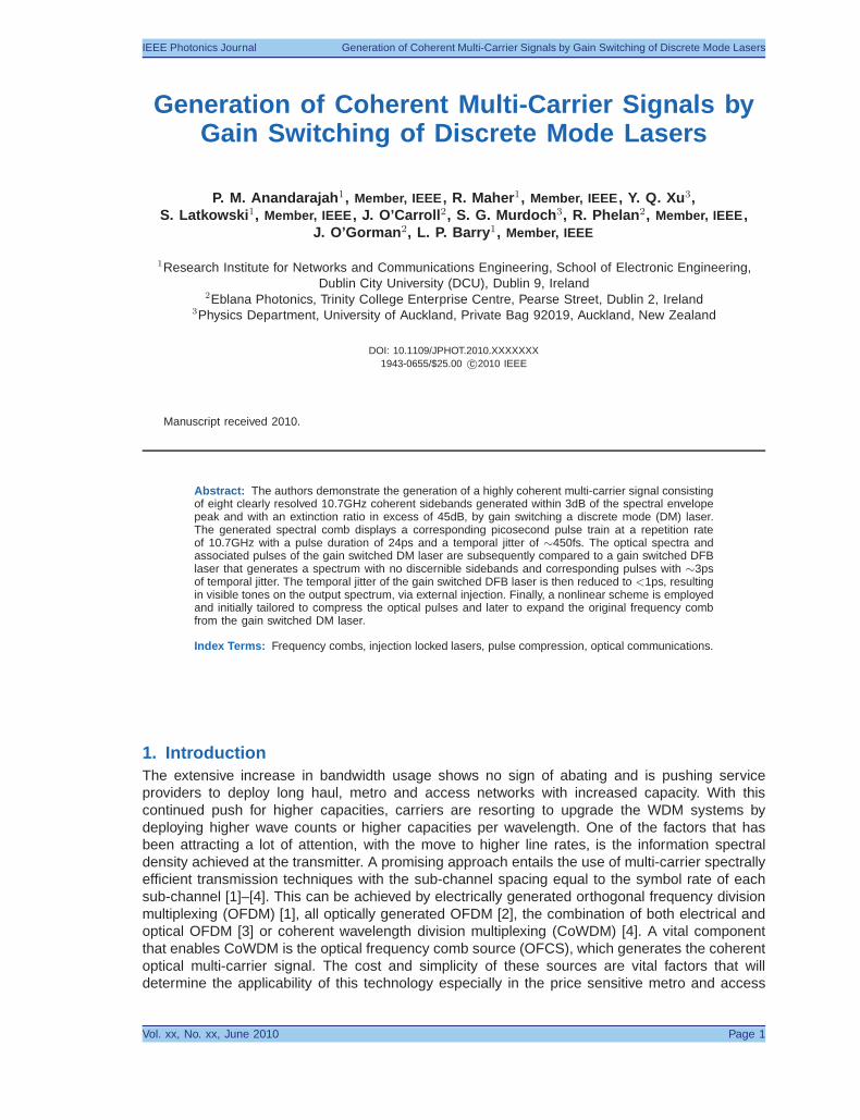
Fig.3 shows the experimental set-up used to realize the delayed self-heterodyne (DS-H) linewidthcharacterization [15]. The fiber delay length in one arm of the set-up is 12km (corresponding to alinewidth measurement resolution of ∼10kHz). Light propagating in the short arm of the set-up ismodulated using a LiNbO3 phase modulator to frequency shift the detected heterodyne beat signalto 2GHz, thereby enhancing the measurement accuracy. The laser linewidth is then deduced fromthe beat frequency spectrum between the delayed and the non-delayed light, measured using anelectrical spectrum analyzer (ESA).
Fig. 3. Experimental set-up for linewidth characterization.
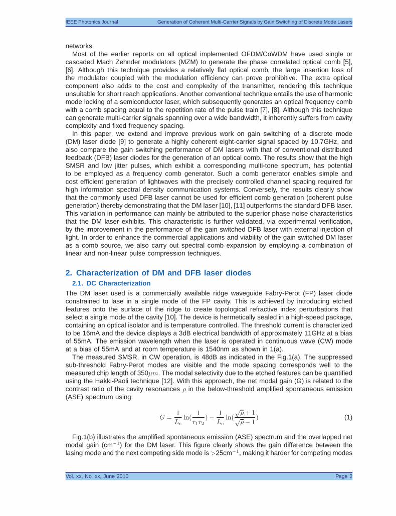
The linewidth of the two lasers (DM and DFB) in CW mode is characterized when they emitfibre coupled output powers of 1 and 2mW and the measured results are shown in Fig.4. TheCW linewidth of the DM laser at output powers (bias currents) of 1mW (34mA) and 2mW (55mA)is measured to be 2 and 1.2MHz respectively. The CW linewidth of the DFB laser at outputpowers (bias current) of 1mW (28mA) and 2mW (48mA) is measured to be 31.8 and 17.8MHz,respectively. This large variation in linewidth between the two types of lasers, when running inCW mode, shows that the DM laser exhibits superior phase noise characteristics.
Fig. 4. Linewidths measured using the DS-H method, yellow line: seeded DFB @ 4mW, black line:CW DM @ 1mW, red line: CW DM @ 2mW, green line: CW DFB @ 1mW and blue line: CW DFB @2mW.
There are two fundamentally inherent mechanisms that contribute to the narrow linewidth exhib-ited by the DM laser. Firstly the FP cavity mirror loss strongly enhances one FP mode relative toall other modes that are simultaneously suppressed. This differentially increases the loss for non-lasing cavity modes and reduces the noise amplitude coupled into the lasing mode. Secondly, an
Vol. xx, No. xx, June 2010 Page 4
IEEE Photonics Journal Generation of Coherent Multi-Carrier Signals by Gain Switching of Discrete Mode Lasers
important feature of the DM laser is that the multiple quantum well active region is fabricated in theInGaAlAs material which has a high differential gain. This high differential gain results in a linewidthenhancement factor of approximately 2-3 [16]. As mentioned the laser linewidth induced by theamplitude noise, arises from the spontaneous emission noise through the linewidth enhancementfactor [13]. Therefore the linewidth of the DM laser can be maintained at a low value (1-2MHz),relative to that exhibited by the DFB laser (18-32MHz), which typically has an alpha factor ofapproximately 5.
3. Gain switching of DM and DFB laser diodes3.1. Experimental Set-up
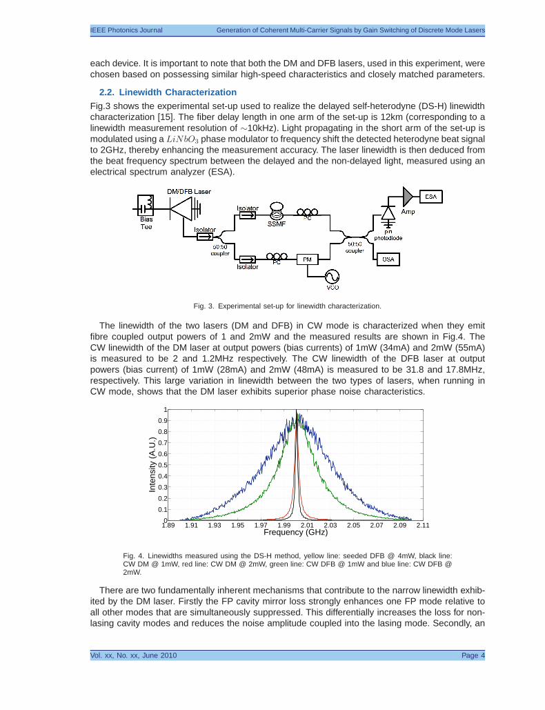
Fig.5 shows the experimental set-up used to realize the gain switching of the DM and DFBlasers characterised in the previous sections. Gain switching is achieved by applying an amplified10.7GHz sinusoidal RF signal (24dBm) in combination with a dc bias (∼4Ith) to the laser viaa bias tee. The optical output of the laser source is split using a 3dB fiber coupler to enablesimultaneous temporal and spectral measurements. The characterization of the multi-carrier signalis carried out by using a high resolution (20MHz) optical spectrum analyzer (OSA) and a high-speed oscilloscope (>65GHz) in conjunction with a 50GHz pin detector.
Fig. 5. Experimental set-up for gain switched DM and DFB lasers.
3.2. Results and Discussion
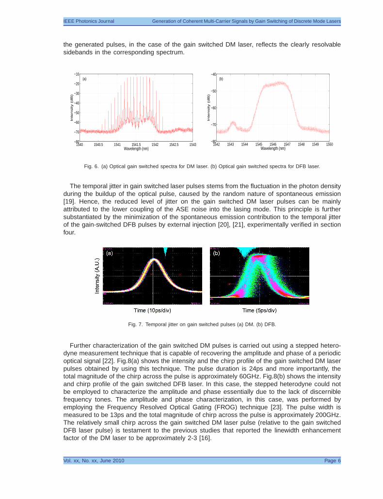
Fig.6(a) shows the spectrum of the gain switched DM laser where the spectral envelope has afull width at half the maximum (FWHM) of approximately 0.5nm. The SMSR is preserved underthe high speed modulation and is greater than 45dB, which is highly advantageous in hybridWDM/OTDM systems [17]. This modulated spectrum also shows efficient sideband generation inthe lasing mode (approximately eight, 10.7GHz sidebands are generated within 3dB of the spectralenvelope peak) and two small equidistant features on either side of the spectrum corresponding tothe sub-threshold FP cavity modes. The high modulation depth of >45dB indicates the excellentpulse-to-pulse phase stability and also the phase co-relation of the emitted pulses [18]. Fig.6(b)displays the corresponding spectrum of the gain switched DFB laser. In contrast to the gainswitched DM laser, modulation of the DFB laser results in a significantly broadened spectrum[8]. In addition, the peak to background spectral contrast reduces to 32dB, which would resultin degraded performance if the DFB based transmitter is implemented in a hybrid WDM/OTDMsystem [17].
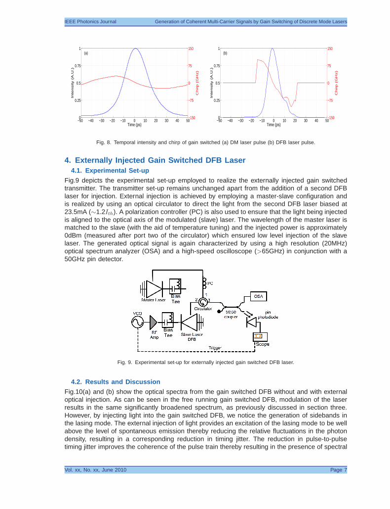
Fig.7(a) and (b) show the measured optical pulses from the gain switched DM and DFB lasers,respectively. The pulse width for the gain switched DM laser is 24ps while the pulse width for thegain switched DFB laser is 13ps. We attribute the shorter pulse width of the DFB laser to therelatively higher bandwidth ∼16GHz (in comparison to the DM laser which has a bandwidth of11GHz). More importantly the root mean squared (RMS) jitter of the gain switched DM pulsesis measured to be ∼450fs while that of the DFB is measured to be ∼3ps. The reduced jitter on
Vol. xx, No. xx, June 2010 Page 5
IEEE Photonics Journal Generation of Coherent Multi-Carrier Signals by Gain Switching of Discrete Mode Lasers
the generated pulses, in the case of the gain switched DM laser, reflects the clearly resolvablesidebands in the corresponding spectrum.
1540 1540.5 1541 1541.5 1542 1542.5 1543−80
−70
−60
−50
−40
−30
−20
−10
Wavelength (nm)
Inte
nsity (
dB
)
(a)
1542 1543 1544 1545 1546 1547 1548 1549 1550−80
−70
−60
−50
−40
Inte
nsity (
dB
)
Wavelength (nm)
(b)
Fig. 6. (a) Optical gain switched spectra for DM laser. (b) Optical gain switched spectra for DFB laser.
The temporal jitter in gain switched laser pulses stems from the fluctuation in the photon densityduring the buildup of the optical pulse, caused by the random nature of spontaneous emission[19]. Hence, the reduced level of jitter on the gain switched DM laser pulses can be mainlyattributed to the lower coupling of the ASE noise into the lasing mode. This principle is furthersubstantiated by the minimization of the spontaneous emission contribution to the temporal jitterof the gain-switched DFB pulses by external injection [20], [21], experimentally verified in sectionfour.
Fig. 7. Temporal jitter on gain switched pulses (a) DM. (b) DFB.
Further characterization of the gain switched DM pulses is carried out using a stepped hetero-dyne measurement technique that is capable of recovering the amplitude and phase of a periodicoptical signal [22]. Fig.8(a) shows the intensity and the chirp profile of the gain switched DM laserpulses obtained by using this technique. The pulse duration is 24ps and more importantly, thetotal magnitude of the chirp across the pulse is approximately 60GHz. Fig.8(b) shows the intensityand chirp profile of the gain switched DFB laser. In this case, the stepped heterodyne could notbe employed to characterize the amplitude and phase essentially due to the lack of discerniblefrequency tones. The amplitude and phase characterization, in this case, was performed byemploying the Frequency Resolved Optical Gating (FROG) technique [23]. The pulse width ismeasured to be 13ps and the total magnitude of chirp across the pulse is approximately 200GHz.The relatively small chirp across the gain switched DM laser pulse (relative to the gain switchedDFB laser pulse) is testament to the previous studies that reported the linewidth enhancementfactor of the DM laser to be approximately 2-3 [16].
Vol. xx, No. xx, June 2010 Page 6
IEEE Photonics Journal Generation of Coherent Multi-Carrier Signals by Gain Switching of Discrete Mode Lasers
−50 −40 −30 −20 −10 0 10 20 30 40 500
0.25
0.5
0.75
1
Time (ps)
Inte
nsity (
A.U
.)
−150
−75
0
75
150
Ch
irp
(G
Hz)
(a)
−50 −40 −30 −20 −10 0 10 20 30 40 500
0.25
0.5
0.75
1
Time (ps)
Inte
nsity (
A.U
.)
−150
−75
0
75
150
Ch
irp
(G
Hz)
(b)
Fig. 8. Temporal intensity and chirp of gain switched (a) DM laser pulse (b) DFB laser pulse.
4. Externally Injected Gain Switched DFB Laser4.1. Experimental Set-up
Fig.9 depicts the experimental set-up employed to realize the externally injected gain switchedtransmitter. The transmitter set-up remains unchanged apart from the addition of a second DFBlaser for injection. External injection is achieved by employing a master-slave configuration andis realized by using an optical circulator to direct the light from the second DFB laser biased at23.5mA (∼1.2Ith). A polarization controller (PC) is also used to ensure that the light being injectedis aligned to the optical axis of the modulated (slave) laser. The wavelength of the master laser ismatched to the slave (with the aid of temperature tuning) and the injected power is approximately0dBm (measured after port two of the circulator) which ensured low level injection of the slavelaser. The generated optical signal is again characterized by using a high resolution (20MHz)optical spectrum analyzer (OSA) and a high-speed oscilloscope (>65GHz) in conjunction with a50GHz pin detector.
Fig. 9. Experimental set-up for externally injected gain switched DFB laser.
4.2. Results and Discussion
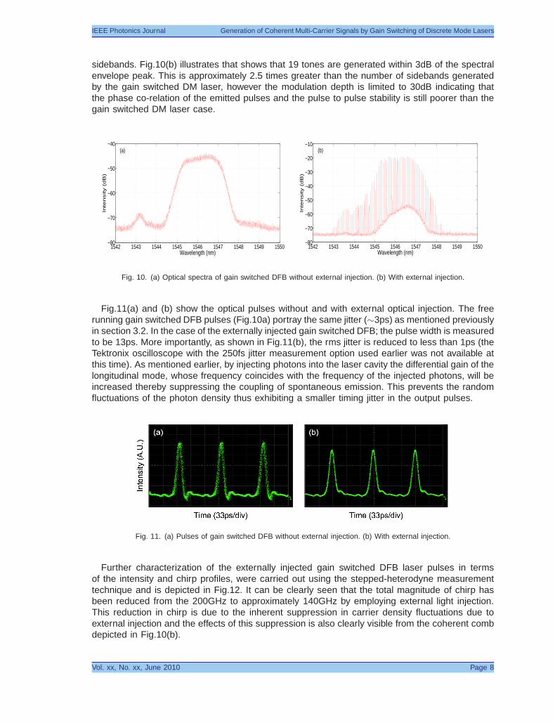
Fig.10(a) and (b) show the optical spectra from the gain switched DFB without and with externaloptical injection. As can be seen in the free running gain switched DFB, modulation of the laserresults in the same significantly broadened spectrum, as previously discussed in section three.However, by injecting light into the gain switched DFB, we notice the generation of sidebands inthe lasing mode. The external injection of light provides an excitation of the lasing mode to be wellabove the level of spontaneous emission thereby reducing the relative fluctuations in the photondensity, resulting in a corresponding reduction in timing jitter. The reduction in pulse-to-pulsetiming jitter improves the coherence of the pulse train thereby resulting in the presence of spectral
Vol. xx, No. xx, June 2010 Page 7
IEEE Photonics Journal Generation of Coherent Multi-Carrier Signals by Gain Switching of Discrete Mode Lasers
sidebands. Fig.10(b) illustrates that shows that 19 tones are generated within 3dB of the spectralenvelope peak. This is approximately 2.5 times greater than the number of sidebands generatedby the gain switched DM laser, however the modulation depth is limited to 30dB indicating thatthe phase co-relation of the emitted pulses and the pulse to pulse stability is still poorer than thegain switched DM laser case.
1542 1543 1544 1545 1546 1547 1548 1549 1550−80
−70
−60
−50
−40
Inte
nsity (
dB
)
Wavelength (nm)
(a)
1542 1543 1544 1545 1546 1547 1548 1549 1550−80
−70
−60
−50
−40
−30
−20
−10
Inte
nsity (
dB
)
Wavelength (nm)
(b)
Fig. 10. (a) Optical spectra of gain switched DFB without external injection. (b) With external injection.
Fig.11(a) and (b) show the optical pulses without and with external optical injection. The freerunning gain switched DFB pulses (Fig.10a) portray the same jitter (∼3ps) as mentioned previouslyin section 3.2. In the case of the externally injected gain switched DFB; the pulse width is measuredto be 13ps. More importantly, as shown in Fig.11(b), the rms jitter is reduced to less than 1ps (theTektronix oscilloscope with the 250fs jitter measurement option used earlier was not available atthis time). As mentioned earlier, by injecting photons into the laser cavity the differential gain of thelongitudinal mode, whose frequency coincides with the frequency of the injected photons, will beincreased thereby suppressing the coupling of spontaneous emission. This prevents the randomfluctuations of the photon density thus exhibiting a smaller timing jitter in the output pulses.
Fig. 11. (a) Pulses of gain switched DFB without external injection. (b) With external injection.
Further characterization of the externally injected gain switched DFB laser pulses in termsof the intensity and chirp profiles, were carried out using the stepped-heterodyne measurementtechnique and is depicted in Fig.12. It can be clearly seen that the total magnitude of chirp hasbeen reduced from the 200GHz to approximately 140GHz by employing external light injection.This reduction in chirp is due to the inherent suppression in carrier density fluctuations due toexternal injection and the effects of this suppression is also clearly visible from the coherent combdepicted in Fig.10(b).
Vol. xx, No. xx, June 2010 Page 8
IEEE Photonics Journal Generation of Coherent Multi-Carrier Signals by Gain Switching of Discrete Mode Lasers
−50 −40 −30 −20 −10 0 10 20 30 40 500
0.25
0.5
0.75
1
Time (ps)In
ten
sity (
A.U
.)
−150
−75
0
75
150
Ch
irp
(G
Hz)
Fig. 12. Temporal intensity and chirp of externally injected gain switched DFB laser.
5. Pulse Compression/Comb Expansion through Self Phase ModulationThe special property of a gain switched DM laser yielding low jitter pulses and a correspondingfrequency comb alludes to the fact that it can be employed as a cost efficient transmitter (by filteringindividual sidebands) in networks utilizing advanced modulation formats and also in CoWDMtransmission systems [24], [25]. The viability of such a source would be vastly improved if thenumber of generated sidebands could be increased. This may be achieved by exploiting thenonlinear effects in standard single mode fiber. If the peak power of the generated pulses issufficient, self phase modulation (SPM) effects in the fiber may be induced and when combinedwith anomalous dispersion, pulse compression occurs. A consequence of pulse compressionis a broader spectral envelope. Therefore this technique is employed to multiply the number offrequency tones present in the gain-switched comb spectrum.
5.1. Experimental Set-up
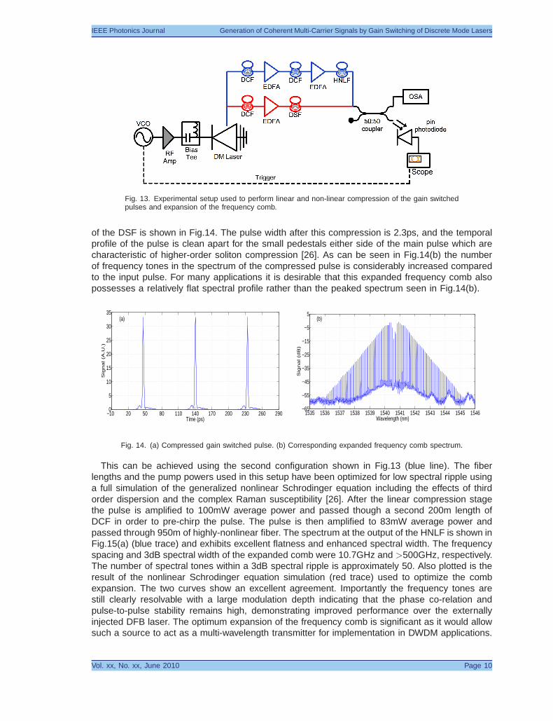
Fig.13 shows the experimental set-up used to compress the generated pulses (red line) andto generate an expanded a low-ripple frequency comb (blue line) from the gain switched DMlaser. The transmitter set-up is unchanged and the optical pulses are passed directly into adispersion compensating fiber (DCF). As shown in Fig.8, the gain switched DM pulses exhibita predominantly linear chirp with a negative slope across the central part of the pulse, thereforenormal dispersion can be employed for compression. The first compression technique (red sectionin Fig.13) employed a 600m span of DCF with a dispersion of -99ps/nm/km at 1540nm. Thepulses are further compressed by the nonlinear technique of higher-order soliton compressionin a dispersion shifted fiber (DSF) [26]. A 4.8km span of dispersion shifted fiber is used for thesoliton compression and it exhibited a dispersion parameter of 4.5ps/nm/km at 1540nm. For thesecond scenario (blue section in Fig.13) the linearly compressed pulses are amplified and passedthrough a second 200m length of DCF followed by a second EDFA and a 950m length of highly-nonlinear fiber (HNLF, dispersion -0.5ps/nm/km) to produce an optical frequency comb optimizedfor low spectral-ripple. For both compression stages the output signal is split using a passive 3dBoptical coupler before being analyzed with a high resolution OSA and a commercially availableoptical sampling oscilloscope with a sampling bandwidth of 500GHz.
5.2. Results and Discussion
After propagating through the 600m of DCF, the pulse duration of the gain-switched DM laser isreduced from 24ps to 11ps. This compressed pulse has a time-bandwidth product of 0.5, closeto the optimum value of 0.44 for a Gaussian pulse. For the higher-order soliton compression thispulse is then amplified to 46 mW average power (peak power 0.42W, soliton number N∼4) andpropagated through 4.8km of DSF. The temporal profile and spectrum of the pulse at the output
Vol. xx, No. xx, June 2010 Page 9
IEEE Photonics Journal Generation of Coherent Multi-Carrier Signals by Gain Switching of Discrete Mode Lasers
Fig. 13. Experimental setup used to perform linear and non-linear compression of the gain switchedpulses and expansion of the frequency comb.
of the DSF is shown in Fig.14. The pulse width after this compression is 2.3ps, and the temporalprofile of the pulse is clean apart for the small pedestals either side of the main pulse which arecharacteristic of higher-order soliton compression [26]. As can be seen in Fig.14(b) the numberof frequency tones in the spectrum of the compressed pulse is considerably increased comparedto the input pulse. For many applications it is desirable that this expanded frequency comb alsopossesses a relatively flat spectral profile rather than the peaked spectrum seen in Fig.14(b).
Fig. 14. (a) Compressed gain switched pulse. (b) Corresponding expanded frequency comb spectrum.
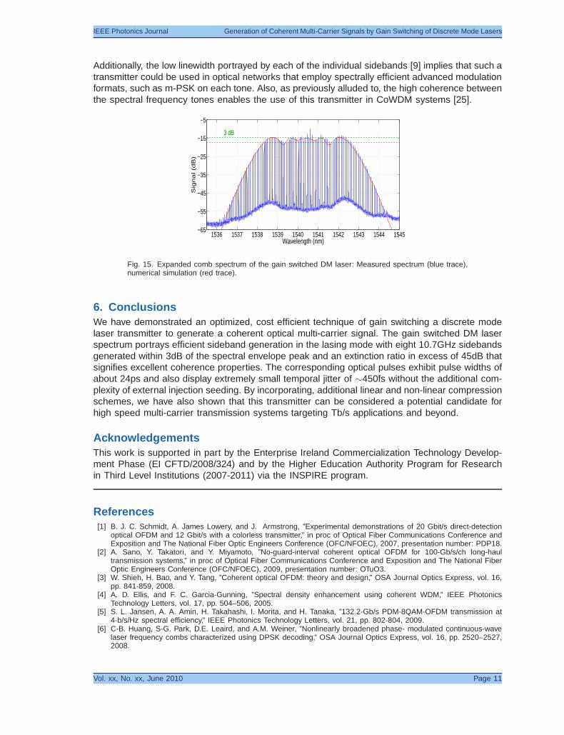
This can be achieved using the second configuration shown in Fig.13 (blue line). The fiberlengths and the pump powers used in this setup have been optimized for low spectral ripple usinga full simulation of the generalized nonlinear Schrodinger equation including the effects of thirdorder dispersion and the complex Raman susceptibility [26]. After the linear compression stagethe pulse is amplified to 100mW average power and passed though a second 200m length ofDCF in order to pre-chirp the pulse. The pulse is then amplified to 83mW average power andpassed through 950m of highly-nonlinear fiber. The spectrum at the output of the HNLF is shown inFig.15(a) (blue trace) and exhibits excellent flatness and enhanced spectral width. The frequencyspacing and 3dB spectral width of the expanded comb were 10.7GHz and >500GHz, respectively.The number of spectral tones within a 3dB spectral ripple is approximately 50. Also plotted is theresult of the nonlinear Schrodinger equation simulation (red trace) used to optimize the combexpansion. The two curves show an excellent agreement. Importantly the frequency tones arestill clearly resolvable with a large modulation depth indicating that the phase co-relation andpulse-to-pulse stability remains high, demonstrating improved performance over the externallyinjected DFB laser. The optimum expansion of the frequency comb is significant as it would allowsuch a source to act as a multi-wavelength transmitter for implementation in DWDM applications.
Vol. xx, No. xx, June 2010 Page 10
IEEE Photonics Journal Generation of Coherent Multi-Carrier Signals by Gain Switching of Discrete Mode Lasers
Additionally, the low linewidth portrayed by each of the individual sidebands [9] implies that such atransmitter could be used in optical networks that employ spectrally efficient advanced modulationformats, such as m-PSK on each tone. Also, as previously alluded to, the high coherence betweenthe spectral frequency tones enables the use of this transmitter in CoWDM systems [25].
Fig. 15. Expanded comb spectrum of the gain switched DM laser: Measured spectrum (blue trace),numerical simulation (red trace).
6. ConclusionsWe have demonstrated an optimized, cost efficient technique of gain switching a discrete modelaser transmitter to generate a coherent optical multi-carrier signal. The gain switched DM laserspectrum portrays efficient sideband generation in the lasing mode with eight 10.7GHz sidebandsgenerated within 3dB of the spectral envelope peak and an extinction ratio in excess of 45dB thatsignifies excellent coherence properties. The corresponding optical pulses exhibit pulse widths ofabout 24ps and also display extremely small temporal jitter of ∼450fs without the additional com-plexity of external injection seeding. By incorporating, additional linear and non-linear compressionschemes, we have also shown that this transmitter can be considered a potential candidate forhigh speed multi-carrier transmission systems targeting Tb/s applications and beyond.
AcknowledgementsThis work is supported in part by the Enterprise Ireland Commercialization Technology Develop-ment Phase (EI CFTD/2008/324) and by the Higher Education Authority Program for Researchin Third Level Institutions (2007-2011) via the INSPIRE program.
References[1] B. J. C. Schmidt, A. James Lowery, and J. Armstrong, ”Experimental demonstrations of 20 Gbit/s direct-detection
optical OFDM and 12 Gbit/s with a colorless transmitter,” in proc of Optical Fiber Communications Conference andExposition and The National Fiber Optic Engineers Conference (OFC/NFOEC), 2007, presentation number: PDP18.
[2] A. Sano, Y. Takatori, and Y. Miyamoto, ”No-guard-interval coherent optical OFDM for 100-Gb/s/ch long-haultransmission systems,” in proc of Optical Fiber Communications Conference and Exposition and The National FiberOptic Engineers Conference (OFC/NFOEC), 2009, presentation number: OTuO3.
[3] W. Shieh, H. Bao, and Y. Tang, ”Coherent optical OFDM: theory and design,” OSA Journal Optics Express, vol. 16,pp. 841-859, 2008.
[4] A. D. Ellis, and F. C. Garcia-Gunning, ”Spectral density enhancement using coherent WDM,” IEEE PhotonicsTechnology Letters, vol. 17, pp. 504–506, 2005.
[5] S. L. Jansen, A. A. Amin, H. Takahashi, I. Morita, and H. Tanaka, ”132.2-Gb/s PDM-8QAM-OFDM transmission at4-b/s/Hz spectral efficiency,” IEEE Photonics Technology Letters, vol. 21, pp. 802-804, 2009.
[6] C-B. Huang, S-G. Park, D.E. Leaird, and A.M. Weiner, ”Nonlinearly broadened phase- modulated continuous-wavelaser frequency combs characterized using DPSK decoding,” OSA Journal Optics Express, vol. 16, pp. 2520–2527,2008.
Vol. xx, No. xx, June 2010 Page 11
IEEE Photonics Journal Generation of Coherent Multi-Carrier Signals by Gain Switching of Discrete Mode Lasers
[7] F. Quinlan, S. Gee, S. Ozharar, and P. Delfyett, ”Ultralow-jitter and amplitude-noise semiconductor-based activelymode-locked laser,” OSA Optics Letters, vol. 31, pp. 2870–2872, 2006.
[8] R. G. M. P. Koumans, and R. Van Roijen, ”Theory for passive mode-locking in semiconductor laser structures includingthe effects of self-phase modulation, dispersion, and pulse collisions,” IEEE Journal of Quantum Electronics, vol. 32,pp. 478–492, 1996.
[9] P. M. Anandarajah, K. Shi, J. OCarroll, A. Kaszubowska, R. Phelan, L. P. Barry, A. D. Ellis, P. Perry, D. Reid, B. Kelly,and J. OGorman, ”Phase shift keyed systems based on a gain switched laser transmitter,” OSA Journal OpticsExpress, vol. 17, pp. 12668-12677, 2009.
[10] C. Herbert, D. Jones, A. Kaszubowska-Anandarajah, B. Kelly, M. Rensing, J. O’Carroll, R. Phelan, P. Anandarajah,P. Perry, L. P. Barry, and J. O’Gorman, ”Discrete mode lasers for communication applications,” IET Optoelectronics,vol. 3, pp. 1-17, 2009.
[11] R. Phelan, B. Kelly, J. OCarroll, C. Herbert, A. Duke, and J. OGorman. ”−40C < T < 95C mode-hop free operationof an uncooled AlGaInAs-MQW discrete-mode laser diode with emission at 1.3µm,” IET Electronics Letters, vol. 45,pp. 43-45, 2009.
[12] B. W. Hakki, and T. L. Paoli, ”CW degradation at 300 K of GaAs double heterostructure junction lasers. II. Electronicgain,” Journal of Applied Physics, vol. 44, pp. 41134119, 1973.
[13] Y. Takushima, H. Sotobayashi, M. E. Grein. E. P. Ippen, and H. H. Haus, ”Linewidth of mode combs of passively andactively mode locked semiconductor laser diodes,” in Proc. SPIE, 2004, vol. 5595, pp. 213-227.
[14] C. H. Henry, ”Theory of the linewidth of semiconductor lasers,” IEEE Journal of Selected Topics in QuantumElectronics, vol. QE-18, pp. 259-264, 1982.
[15] T. Okoshi, K. Kikuchi, and A. Nakajama, ”Novel method for high resolution measurement of laser output measure-ments,” IET Electronics Letters, vol. 16, pp. 630-631, 1980.
[16] R. Fehse, S. OBrien, S. Osborn, E. P. OReilly, J. Patchell, D. Jones, and J. OGorman, ”Design and implementationof single-mode Fabry-Perot lasers using non-periodic index patterns,” Part of Proceedings of SPIE 6115 Physics andSimulation of Optoelectronic Devices XIV, 2006, 6115-06.
[17] P. Anandarajah, L. P. Barry, and A. Kaszubowska, ”Performance Issues Associated with WDM Optical Systems usingSelf-Seeded Gain-Switched Pulse Sources due to Mode Partition Noise Effects,” IEEE Photonics Technology Letters,vol. 14, pp. 1202-1204, 2002.
[18] C. Schubert. S. Ferber, M. Kroh, C. Schmidt-Langhorst, R. Ludwig, B. Huttl, R. Kaiser, and H. G. Weber, ”40 GHzsemiconductor mode locked laser pulse source for 160Gbit/s RZ-DPSK data transmission,” in proc. of EuropeanConference on Optical Communications (ECOC), 2005, presentation number: Tu1.5.3.
[19] M. Jinno, ”Correlated and uncorrelated timing jitter in gain switched laser diodes,” IEEE Photonics Technology Letters,vol. 5, pp. 1140–1143, 1993.
[20] D. S. Seo, D. Y. Kim, and H. F. Liu, ”Timing jitter reduction of gain-switched DFB laser by external injection-seeding,”IET Electronics Letters, vol. 32, pp. 44-45, 1996.
[21] A. M. Clarke, P. Anandarajah, and L. P. Barry, ”Generation of widely tunable picosecond pulses with large SMSR byexternally injecting a gain-switched dual laser source,” IEEE Photonics Technology Letters, vol. 16, pp. 2344–2346,2004.
[22] D. A. Reid, S. G. Murdoch, and L. P. Barry, ”Stepped-heterodyne optical complex spectrum analyser,” OSA JournalOptics Express, vol. 18, pp. 19724-19731, 2010.
[23] R. Trebino, K. W. DeLong, D. N. Fittinghoff, J. N. Sweetser, M. A. Krumbugel, and B. A. Richman, ”Measuringultrashort laser pulses in the time-frequency domain using frequency-resolved optical gating,” Review of ScientificInstruments, vol. 68, pp. 3277-3295, 1997.
[24] A. D. Ellis, F. C. Garcia-Gunning, and T. Healy, ”Coherent WDM: The achievement of high information spectral densitythrough phase control within the transmitter,” in proc of Optical Fiber Communications Conference and Expositionand The National Fiber Optic Engineers Conference (OFC/NFOEC), 2005, presentation number: OThR4.
[25] R. Maher, P. M. Anandarajah, S. K. Ibrahim, L. Barry, A. Ellis, P. Perry, R. Phelan, B. Kelly, and J. O’Gorman, ”Lowcost comb source in a coherent wavelength division multiplexed system,” in proc. of European Conference on OpticalCommunications (ECOC), 2010, presentation number: We. P3.07.
[26] G. P. Agrawal, ”Applications of nonlinear fiber optics,” Academic Press, 2001.


![Coherent Detection of Turbo-Coded OFDM Signals … · an OFDM frame when it is not present) ... synchronization for OFDM are given in [15]– ... Detection of OFDM signals, ...](https://static.documents.pub/doc/80x56/5ae5fd777f8b9a08778c6dfc/coherent-detection-of-turbo-coded-ofdm-signals-ofdm-frame-when-it-is-not-present.jpg)