OCIS codes: (060.2330) Fiber optics communications; (060.2630) Frequency modulation;
(060.2320) Fiber optics amplifiers and oscillators.
References and links
1. T. Sakamoto, T. Yamamoto, K. Kurokawa, and S. Tomita, “DWDM transmission in O-band over 24 km PCF using
optical frequency comb based multicarrier source,” Electron. Lett. 45(16), 850–851 (2009).
2. S. Liu and T. Trina, Ng, David J. Richardson, Periklis Petropoulos. “An optical frequency comb generator as a
broadband pulse source,” OFC. OThG7, (2009).
3. Y. Ma, Q. Yang, Y. Tang, S. Chen, and W. Shieh, “1-Tb/s single-channel coherent optical OFDM transmission
over 600-km SSMF fiber with subwavelength bandwidth access,” Opt. Express 17(11), 9421–9427 (2009).
4. X. Liu, S. Chandrasekhar, B. Zhu, D. Peckham, “Efficient digital coherent Detection of a 1.2-Tb/s 24-carrier
no-guard-interval CO-OFDM signal by simultaneously detecting multiple carriers per sampling,” OFC. OWO2
(2010).
5. F. Tian, X. Zhang, J. Li, and L. Xi, “Generation of 50 stable frequency-locked optical carriers for Tb/s multicarrier
optical transmission using a recirculating frequency shifter,” J. Lightwave Technol. 29(8), 1085–1091 (2011).
6. J. Yu, Z. Dong, and N. Chi, “1.96-Tb/s (21x100 Gb/s) optical OFDM superchannel generation and transmission
over 3200-km SMF-28 with EDFA-only,” IEEE Photon. Technol. Lett. 23, 1061–1063 (2011).
7. J. Yu, “1.2 Tbit/s orthogonal PDM-RZ-QPSK DWDM signal transmission over 1040 km SMF-28,” Electron. Lett.
46(11), 775–777 (2010).
8. G. Gavioli, E. Torrengo, G. Bosco, A. Carena, S. Savory, F. Forghieri, and P. Poggiolin, “Ultra-narrow-spacing
10-channel 1.12 Tb/s D-WDM long-haul transmission over uncompensated SMF and NZDSF,” IEEE Photon.
Technol. Lett. 22(19), 1419–1421 (2010).
9. B. Zhu, X. Liu, S. Chandrasekhar, D. Peckham, and R. Lingle, “Ultra-long-haul transmission of 1.2-Tb/s
multicarrier no-guard-interval CO-OFDM superchannel using ultra-large-area fiber,” IEEE Photon. Technol. Lett.
22(11), 826–828 (2010).
10. Y. Tang and W. Shieh, “Coherent optical OFDM transmission up to 1 Tb/s per channel,” J. Lightwave Technol.
27(16), 3511–3517 (2009).
11. S. Chandrasekhar, X. Liu, B. Zhu, D. Peckham, “Transmission of a 1.2-Tb/s 24-carrier no-guard-interval coherent
OFDM superchannel over 7200-km of ultra-large-area Fiber,” ECOC. PD2.6 (2009).
#157307 - $15.00 USD Received 28 Oct 2011; accepted 20 Nov 2011; published 9 Dec 2011(C) 2011 OSA 19 December 2011 / Vol. 19, No. 27 / OPTICS EXPRESS 26370
12. H. Masuda, E. Yamazaki, A. Sano, T. Yoshimatsu, T. Kobayashi, E. Yoshida, Y. Miyamoto, S. Matsuoka, Y.
Takatori, M. Mizoguchi, K. Okada, K. Hagimoto, T. Yamada, S. Kamei, “13.5-Tb/s (135 × 111-Gb/s/ch)
no-guard-interval coherent OFDM transmission over 6,248 km using SNR maximized second-order DRA in the
extended L-band,” OFC. PDPB5 (2009).
13. T. Healy, F. C. Garcia Gunning, A. D. Ellis, and J. D. Bull, “Multi-wavelength source using low drive-voltage
amplitude modulators for optical communications,” Opt. Express 15(6), 2981–2986 (2007).
14. J. Li, X. Li, X. Zhang, F. Tian, and L. Xi, “Analysis of the stability and optimizing operation of the
single-side-band modulator based on re-circulating frequency shifter used for the T-bit/s optical communication
PDM-QPSK optical signal has been generated by comb generation or supercontinuum
technique [19]. However, due to the limited optical signal noise ratio (OSNR) of the OFDM
optical signal generation by supercontinuum technique, the transmission distance is quite
limited. Also, 1.96 Tb/s PDM- QPSK OOFDM [6] optical signal is reported by using
multi-carriers generated by cascaded modulators. However, only 21 subcarriers (25 GHz
spacing) covering about 525GHz bandwidth with flat spectrum amplitude [6] is generated due
to the limited amplitude of the RF signals on the phase modulator. Recirculating frequency
#157307 - $15.00 USD Received 28 Oct 2011; accepted 20 Nov 2011; published 9 Dec 2011(C) 2011 OSA 19 December 2011 / Vol. 19, No. 27 / OPTICS EXPRESS 26371
shifter (RFS) based on the frequency shifting in a SSB modulator has been reported to generate
36 and 50 subcarrier, which shows the potential capability to generate more subcarriers
[3–5,14]. However, the total number of subcarriers is strictly depended on the recirculating
times because only one subcarrier generated each time for SSB modulation. Also, the SSB
modulator based RFS has the significant stability problem due to the nonlinearity, the
imbalance of DC bias, and the imbalance of I/Q RF signals of optical I/Q modulator (IQM)
[14]. Due to the mode competition, the amount of multi-carriers is also limited less than 26 in
the schemes in multi-wavelength EDFL in [15–18]. On the other hand, phase modulation in
amplified re-circulating loop has shown the possibility to generate optical multi-carriers with
theoretical prediction in [20–23]. However, a sawtooth RF drive signal is needed for SSB
modulation in [20] which is complex and high-cost. This scheme is first proposed and predicted
by [21]. Also, experiment results of [22,23] show 1.8THz optical comb generation by this
scheme with absolute frequency accuracy and only one active mode-locked loop is used.
Recently we have reported a novel scheme to generate about 112 coherent optical subcarriers
with the subcarriers spacing of 25GHz using two cascade phase modulators and RFS based on
one EDFA loop [24,25]. The feasibility and the good performance of this scheme have been
demonstrated by the generation and transmission of 11.2 Tb/s OOFDM signal per channel [24].
However, due to the mode competition and gain limitation in EDFA, the number of the
generated carriers is limited. Also, the phase deviation of RF drive signals on two phase
modulators should be carefully controlled to generate more subcarriers [25].
In this paper, we improve the previous work and demonstrate the generation of full C-band
coherent and frequency-lock multi-carriers by using two recirculating frequency shifter (RFS)
EDFA loops based on phase modulator with external injection seeding. The two EDFA loops
are actively mode-locked by phase modulators and also frequency-locked by external injection
locking. In our proposed novel scheme, only one phase modulator is used in each loop reducing
the loss and complexity and two loops are used to generate long wavelength and short
wavelength subcarriers respectively. Finally, full C-band with 178 subcarriers and 26GHz
subcarrier frequency spacing covering 36.66 nm from 1527.54 to 1564.20 nm are obtained. The
performance of 178 subcarriers with superior flatness less than 3dB and tone-to-noise ratio
(TNR) larger than 20dB after a wavelength selective switch (WSS) shows that this novel
scheme is a potential technique for the future over 10Tb/s optical communication [24].
#157307 - $15.00 USD Received 28 Oct 2011; accepted 20 Nov 2011; published 9 Dec 2011(C) 2011 OSA 19 December 2011 / Vol. 19, No. 27 / OPTICS EXPRESS 26372
2. The principle of full C-band multi-carriers generation
Fig. 1. Schematic configuration of the full C-band multi-carriers generation by using two RFS
EDFA loops based on phase modulator (ECL: external cavity laser; OC: optical coupler
(polarization maintaining); PM: phase modulator; TD: tunable delay line (polarization
Figure 1 shows the principle of the full C-band multi-carriers generation by using two RFS
EDFA loops based on phase modulator. The configuration of the proposed scheme consists of
two closed loops, and each loop comprises with two 50:50 polarization maintaining optical
couplers, one phase modulator to generate multi-carriers, a polarization maintaining EDFA
amplifier to compensate the loop loss and a polarization maintaining optical tunable delay line
which is used to adjust the recirculating loop length for synchronization [21]. Different from the
previous work in [24,25], in this novel scheme, we use two RFS EDFA loops (Loop1 and Loop
2 shown in Fig. 1) to generate long wavelength and short wavelength subcarriers, respectively.
Also, only one phase modulator is used in each loop which reduces the cost and complexity and
most importantly there is no RF signals phase deviation problem. The CW lightwave generated
from one narrow linewidth ECL is split by one optical coupler as the seed source for each RFS
EDFA loop. The upper loop is free run to generate the long wavelength subcarriers. In order to
lock the generated multi-carriers of Loop2 in the short wavelengths band, one tunable optical
band-pass filter in short wavelength with a polarization controller for polarization maintaining
is used in the lower loop (Loop2) as shown in Fig. 1. By combining the two outputs of Loop1
and Loop2 to pass through a wavelength selective switch (WSS) or waveform shaper, we can
shape the amplitude of each subcarrier and cut off the overlapped spectrum from one loop to
obtain wanted subcarriers. Finally, we can generate flattened subcarriers covering the whole
C-band.
Considering the EDFA loops with the RFS configuration in Fig. 1 as Loop 1 and Loop 2, in
each round the output of phase modulator is split into two branches by optical coupler, one
coupled out and the other recirculating back into a EDFA to compensate the losses in the closed
loop. This scheme induces power transferring to subcarriers in the loop round by round as
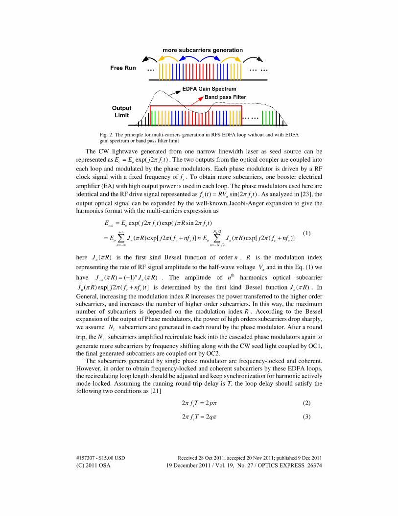
analyzed in previous [21,25]. The principle for multi-carriers generation by RFS EDFA loop is
shown in Fig. 2, in which the output limited by EDFA gain spectrum or band pass filter is
considered.
#157307 - $15.00 USD Received 28 Oct 2011; accepted 20 Nov 2011; published 9 Dec 2011(C) 2011 OSA 19 December 2011 / Vol. 19, No. 27 / OPTICS EXPRESS 26373
Fig. 2. The principle for multi-carriers generation in RFS EDFA loop without and with EDFA
gain spectrum or band pass filter limit
The CW lightwave generated from one narrow linewidth laser as seed source can be
represented as exp( 2 )c o c
E E j f tπ= . The two outputs from the optical coupler are coupled into
each loop and modulated by the phase modulators. Each phase modulator is driven by a RF
clock signal with a fixed frequency ofs
f . To obtain more subcarriers, one booster electrical
amplifier (EA) with high output power is used in each loop. The phase modulators used here are
identical and the RF drive signal represented as ( ) sin(2 )s s
f t RV f tπ π= . As analyzed in [23], the
output optical signal can be expanded by the well-known Jacobi-Anger expansion to give the
harmonics format with the multi-carriers expression as
1
1
2
2
exp( 2 )exp( sin 2 )
( )exp[ 2 ( )] ( ) exp[ 2 ( )]
out o c s
N
o n c s o n c s
n n N
E E j f t j R f t
E J R j f nf E J R j f nf
π π π
π π π π+∞
=−∞ =−
=
= + ≈ +∑ ∑ (1)
here ( )n
J Rπ is the first kind Bessel function of order n , R is the modulation index
representing the rate of RF signal amplitude to the half-wave voltage Vπ and in this Eq. (1) we
have ( ) ( 1) ( )n
n nJ R J Rπ π− = − . The amplitude of n
th harmonics optical subcarrier
( ) exp[ 2 ( ) ]n c s
J R j f nf tπ π + is determined by the first kind Bessel function ( )n
J Rπ . In
General, increasing the modulation index R increases the power transferred to the higher order
subcarriers, and increases the number of higher order subcarriers. In this way, the maximum
number of subcarriers is depended on the modulation index R . According to the Bessel
expansion of the output of Phase modulators, the power of high orders subcarriers drop sharply,
we assume 1
N subcarriers are generated in each round by the phase modulator. After a round
trip, the1
N subcarriers amplified recirculate back into the cascaded phase modulators again to
generate more subcarriers by frequency shifting along with the CW seed light coupled by OC1,
the final generated subcarriers are coupled out by OC2.
The subcarriers generated by single phase modulator are frequency-locked and coherent.
However, in order to obtain frequency-locked and coherent subcarriers by these EDFA loops,
the recirculating loop length should be adjusted and keep synchronization for harmonic actively
mode-locked. Assuming the running round-trip delay is T, the loop delay should satisfy the
following two conditions as [21]
2 2s
f T pπ π= (2)
2 2c
f T qπ π= (3)
#157307 - $15.00 USD Received 28 Oct 2011; accepted 20 Nov 2011; published 9 Dec 2011(C) 2011 OSA 19 December 2011 / Vol. 19, No. 27 / OPTICS EXPRESS 26374
here p is an small integer and q is a large integer, which means the loop resonance frequency
must be an integral subharmonic of both the RF driving frequency and the input optical
frequency. These conditions can be satisfied by carefully adjusting the loop to the proper length
and keep synchronization. In this way, the loop length of the ring is adjusted so that the round
trip time of the loop length matches the modulator frequency to achieve stable active
mode-locking.
Under above phase conditions, the phase delay for each subcarrier after every round should
be integral multiple of 2π . Therefore, the transfer function considering EDFA and cascaded
phase modulators for each round trip can be express as
1
1
2
2
( ) exp( ) ( ) exp( 2 )N
r r n s
n N
F t g a J R j nf tπ π=−
= − ∑ (4)
where r
g is the EDFA amplify gain factor and the exp( )r
α− represents the total insertion
losses in the loop for each round trip. As shown in Eq. (4), the gain of EDFA should be large
enough to compensate all the insertion losses and modulation loss for 1
2N order subcarriers
to run following round trips to generate more subcarriers. For saturation and stable case, we
have exp( ) 1r r
g a− = . All the generated subcarriers still satisfy the synchronization loop length
conditions as shown in Eqs. (2) and (3). Therefore, the newly generated nth
subcarrier is the
coherent addition of all the subcarriers at frequency of c s
f nf+ generated from different
frequency subcarriers with frequency shifting based on the phase modulation. Assuming the
losses in the closed loop are compensated and making some simplifications, the normalized
outputs after each round trip can be expressed as
1
1
1
1
2
_1
2
2
_ 2 _1 _1
2
2
_ 3 _1 _ 2 _1
exp( ) exp( 2 ) ( ) exp( 2 )
exp( 2 ) ( ) exp( 2 ) (1 )
(1 )
......
N
out o r r c n c s
n N
N
out o c n c s out out
n N
out out out out
E E g a j f t J R j nf t
E E j f t J R j nf t E F E F
E E E F E F F
π π π
π π π
=−
=−
= −
= + = +
= + = + +
∑
∑ (5)
Assuming after K round through the recirculating loop, the amount of generated subcarriers
reach the largest and the bandwidth covering by the total subcarriers reach the largest band
which is limited by EDFA gain spectrum or band-pass filter. The output can be expressed in a
simple format as
2 1
_ _1(1 ...... )
(1 )exp( 2 )
1
K
out K out
K
o c
E E F F F
F FE j f t
Fπ
−= + + + +
−=
−
(6)
As shown in Eq. (6), when the loop input is derived from a laser locked to an absolute
frequency, each of the output subcarriers frequencies is locked and has an absolute accuracy
approaching that of the input. Here, K is the number of round times. For free run loops, K can
approach infinity if the gain is constant for infinite bandwidth and can compensate all the
insertion losses as well as the modulation loss theoretically. However, in practice, the effective
K which determines the amount of output subcarrier is limited by the amplifier gain spectrum
and also can be limited by the induced band pass filter. As analyzed in [23], due to the power
limit of EDFA and the mode competition, the final output bandwidth is limited by the EDFA
gain spectrum.
Considering the phase modulation, single subcarriers is frequency shifted and power
transferred from adjacent subcarriers which is the coherent addition. However, the resonance
#157307 - $15.00 USD Received 28 Oct 2011; accepted 20 Nov 2011; published 9 Dec 2011(C) 2011 OSA 19 December 2011 / Vol. 19, No. 27 / OPTICS EXPRESS 26375
process which is similar to the conventional ring laser should also be considered as analyzed
above in Eq. (2) and Eq. (3). Assuming exp( ) 1r r
g a− = , the optical filed of nth
(n≠0) subcarrier
after the M (M can be smaller or larger than K) round can be expressed as
1
1
2
1 1
2
exp( ) ( )N
n n i n i
M r M i M
i N
E j E J R Eφ π− −
− −
=−
= +∑ (7)
where 2r s
nf Tφ π= is the round-trip phase delay. Equation (7) shows contribution of both
frequency shifting and power transferring by phase modulation and also the resonance process
with phase delay. When Eq. (2) and Eq. (3) are satisfied, we have exp( ) 1r
jφ = and the whole
process is the coherent addition.
Above analysis gives the operating principle and conditions for coherent and
frequency-locked multi-carriers generation by the RFS EDFA loop based on the phase
modulator. We give the theoretical analysis based on the simplified mathematical derivation
with equations. The impact factors that affect the stability of the system can be analyzed by
above Eqs. (2)~7, including the round-trip delay for loop synchronization, the gain to
compensate the loop loss and the bandwidth limited by gain spectrum or filter.
Note that the noise figure performance and mode competition are not considered in above
analysis. Compared to the conventional active mode-locked fiber ring laser reported in [26–28],
we apply external injection locking with CW seed light to the two harmonic actively
mode-locked EDFA loops in our scheme. Typical setup in active mode-locked fiber ring laser
including gain medium with pumped EDFA and modulators driven by sinusoidal RF signal are
also used for the loops setup in our scheme. The loop length of our scheme should be adjusted
for synchronization which is the same to the principle of harmonic active mode-locked. As
reported in [21–23,29] with injection locking, in order to generate frequency-locked
multi-carriers with narrow linewidth, we use a CW source from an ECL as external injection
seeding with phase modulators driven by large amplitude RF source for wide bandwidth locked
to an absolute frequency. In this way, we can generate more than 100 subcarriers of which the
frequencies are locked and have an absolute accuracy approaching that of the input based on
one loop. Experimental results in [25] show the generation of long wavelength of subcarriers
when the loop runs with the only limitation of EDFA gain spectrum. However, a band pass
filter can be used to limit the subcarriers in appointed gain bandwidth with special selected CW
source wavelength and filter bandwidth as shown in Fig. 2. We can choose a CW source in the
middle of C-band and use a band pass filter to lock the frequency of generated subcarriers in
short wavelength. In this way, it gives a possible to generate the whole C-band with two RFS
EDFA loops which generate the long wavelength and short wavelength respectively.
#157307 - $15.00 USD Received 28 Oct 2011; accepted 20 Nov 2011; published 9 Dec 2011(C) 2011 OSA 19 December 2011 / Vol. 19, No. 27 / OPTICS EXPRESS 26376
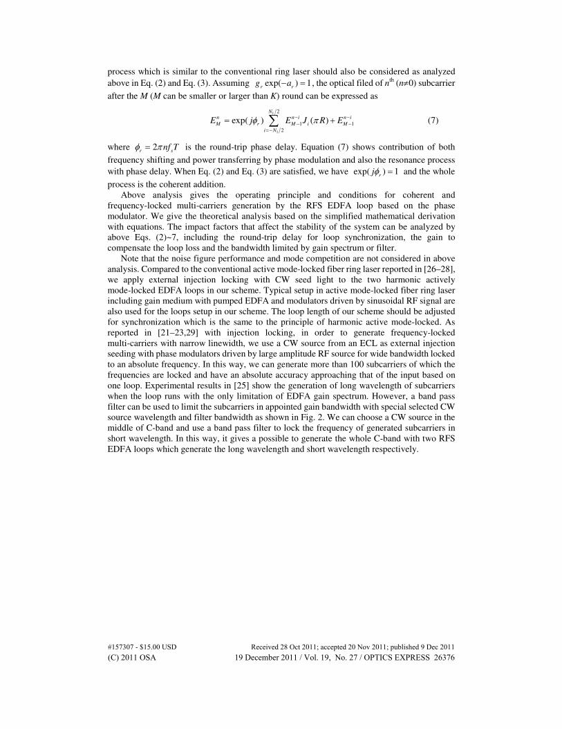
3. Experimental results
Fig. 3. Experiment setup for full C-band multi-carriers generation with two EDFA recirculating
The full C-band multi-carriers generation experiment is carried out as shown in Fig. 3. The seed
CW light source is from a narrow linewidth C-band ECL. The wavelength of ECL we chose
here is 1545.55 nm which is around the middle of C-band. With this wavelength CW seed light,
we can generate both long and short wavelength subcarriers. The output power of the ECL is
14dBm and the linewidth is less than 100 kHz. The RF clock frequency used here is 26 GH and
the RF peak to peak voltage after the booster electrical amplifier is 17V. The half-wave voltage
of the phase modulator is 4V. In this way, the amplitude of the drive RF signal is 8.5V which is
about 2.1 to the half-wave voltage of the phase modulator and we can generate about 13
subcarriers at one time. The CW seed light coupled into two RFS EDFA loops and one optical
band pass filter is used in lower loop.
In our experiment, all the optical couplers, tunable optical delay lines and EDFAs used are
polarization maintaining for stable performance. Also, a polarization controller is used in the
lower loop before the non-polarization maintaining band pass filter. There is no any DC bias
controller in the phase modulator and only one phase modulator is used in each loop, which is
more stable. The phase modulators used have the identical performance. The insertion loss of
phase modulator is 4 dB. The polarization maintaining optical couplers (PM-OC) are also
identical with the insertion loss of 3.1dB and coupling ratio of 50:50. The optical time delay has
an insertion loss of 1.8 dB, which is used for synchronization in the recirculation loop. The
polarization controller used in the lower loop for short wavelength generation has an insertion
loss of 0.5dB. For the lower loop, a band pass filter of 19 nm band width with tunable
wavelength is used with an insertion loss of 6 dB. The lower loop output A and upper loop
output B are combined and pass through a WSS to shape the subcarriers. The impact of EDFA
output power is analyzed in [25]. Therefore, the EDFA output power is larger enough for
compensation the loop loss. In our experiment, we carefully adjust the loop length with the
optical delay line to obtain stable output for active mode-locking loop synchronization
condition. For practice use with long-term stability, these operation factors should be controlled
carefully. The small drifting of RF frequency or small perturbation such as a mechanical
vibration or thermal expansion applied to the loop length in a long time can cause unstable
output and phase mismatch for mode-locking synchronization condition. However, this
problem can be overcome by structures such as regenerative mode-locking feedback circuit in
[26,28]. Further research of the long term stability is under way.
#157307 - $15.00 USD Received 28 Oct 2011; accepted 20 Nov 2011; published 9 Dec 2011(C) 2011 OSA 19 December 2011 / Vol. 19, No. 27 / OPTICS EXPRESS 26377
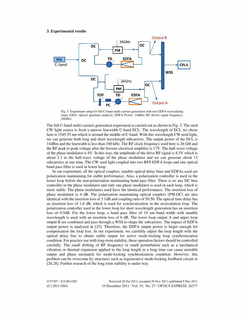
Fig. 4. The optical spectrum after phase modulator with 13 subcarriers generated.
After the phase modulator driven by RF sinuous signal, about 13 subcarriers are generated
with subcarrier frequency spacing of 26GHz as shown in Fig. 4. The power of CW source seed
light transfers to the generated side band subcarriers in the phase modulation. The optical
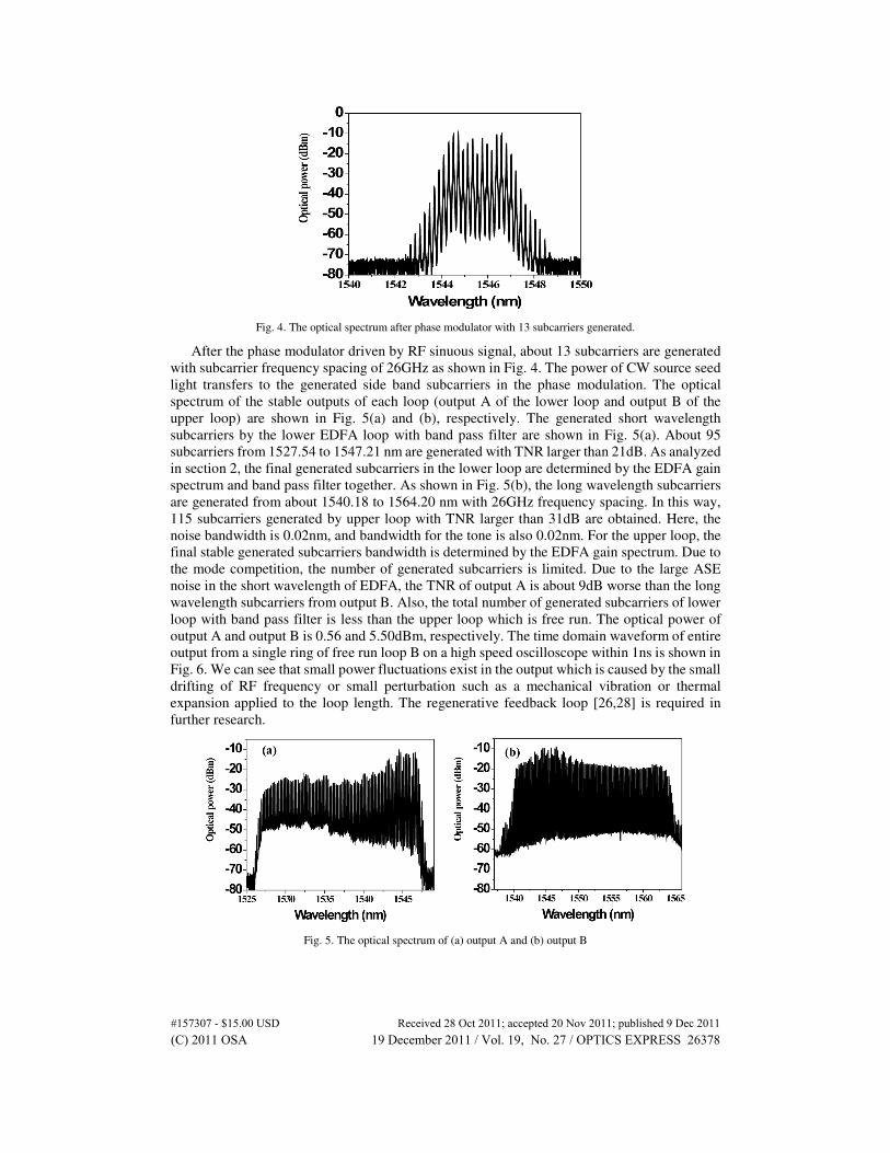
spectrum of the stable outputs of each loop (output A of the lower loop and output B of the
upper loop) are shown in Fig. 5(a) and (b), respectively. The generated short wavelength
subcarriers by the lower EDFA loop with band pass filter are shown in Fig. 5(a). About 95
subcarriers from 1527.54 to 1547.21 nm are generated with TNR larger than 21dB. As analyzed
in section 2, the final generated subcarriers in the lower loop are determined by the EDFA gain
spectrum and band pass filter together. As shown in Fig. 5(b), the long wavelength subcarriers
are generated from about 1540.18 to 1564.20 nm with 26GHz frequency spacing. In this way,
115 subcarriers generated by upper loop with TNR larger than 31dB are obtained. Here, the
noise bandwidth is 0.02nm, and bandwidth for the tone is also 0.02nm. For the upper loop, the
final stable generated subcarriers bandwidth is determined by the EDFA gain spectrum. Due to
the mode competition, the number of generated subcarriers is limited. Due to the large ASE
noise in the short wavelength of EDFA, the TNR of output A is about 9dB worse than the long
wavelength subcarriers from output B. Also, the total number of generated subcarriers of lower
loop with band pass filter is less than the upper loop which is free run. The optical power of
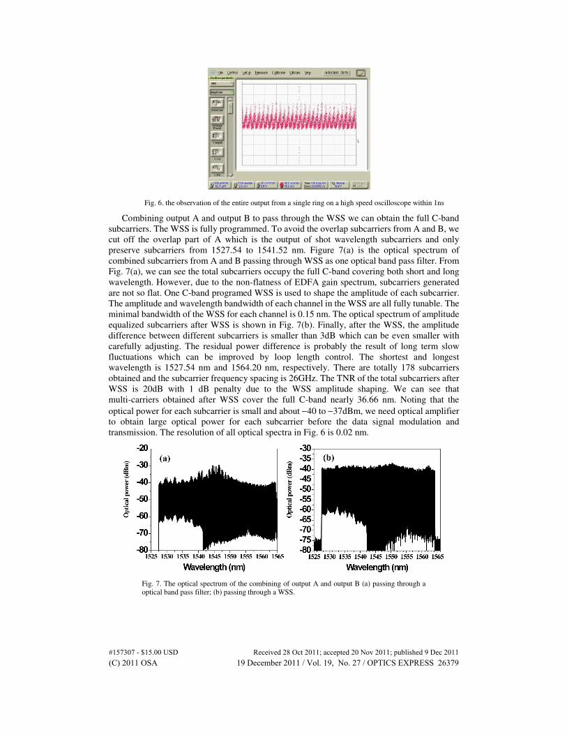
output A and output B is 0.56 and 5.50dBm, respectively. The time domain waveform of entire
output from a single ring of free run loop B on a high speed oscilloscope within 1ns is shown in
Fig. 6. We can see that small power fluctuations exist in the output which is caused by the small
drifting of RF frequency or small perturbation such as a mechanical vibration or thermal
expansion applied to the loop length. The regenerative feedback loop [26,28] is required in
further research.
Fig. 5. The optical spectrum of (a) output A and (b) output B
#157307 - $15.00 USD Received 28 Oct 2011; accepted 20 Nov 2011; published 9 Dec 2011(C) 2011 OSA 19 December 2011 / Vol. 19, No. 27 / OPTICS EXPRESS 26378
Fig. 6. the observation of the entire output from a single ring on a high speed oscilloscope within 1ns
Combining output A and output B to pass through the WSS we can obtain the full C-band
subcarriers. The WSS is fully programmed. To avoid the overlap subcarriers from A and B, we
cut off the overlap part of A which is the output of shot wavelength subcarriers and only
preserve subcarriers from 1527.54 to 1541.52 nm. Figure 7(a) is the optical spectrum of
combined subcarriers from A and B passing through WSS as one optical band pass filter. From
Fig. 7(a), we can see the total subcarriers occupy the full C-band covering both short and long
wavelength. However, due to the non-flatness of EDFA gain spectrum, subcarriers generated
are not so flat. One C-band programed WSS is used to shape the amplitude of each subcarrier.
The amplitude and wavelength bandwidth of each channel in the WSS are all fully tunable. The
minimal bandwidth of the WSS for each channel is 0.15 nm. The optical spectrum of amplitude
equalized subcarriers after WSS is shown in Fig. 7(b). Finally, after the WSS, the amplitude
difference between different subcarriers is smaller than 3dB which can be even smaller with
carefully adjusting. The residual power difference is probably the result of long term slow
fluctuations which can be improved by loop length control. The shortest and longest
wavelength is 1527.54 nm and 1564.20 nm, respectively. There are totally 178 subcarriers
obtained and the subcarrier frequency spacing is 26GHz. The TNR of the total subcarriers after
WSS is 20dB with 1 dB penalty due to the WSS amplitude shaping. We can see that
multi-carriers obtained after WSS cover the full C-band nearly 36.66 nm. Noting that the
optical power for each subcarrier is small and about −40 to −37dBm, we need optical amplifier
to obtain large optical power for each subcarrier before the data signal modulation and
transmission. The resolution of all optical spectra in Fig. 6 is 0.02 nm.
Fig. 7. The optical spectrum of the combining of output A and output B (a) passing through a
optical band pass filter; (b) passing through a WSS.
#157307 - $15.00 USD Received 28 Oct 2011; accepted 20 Nov 2011; published 9 Dec 2011(C) 2011 OSA 19 December 2011 / Vol. 19, No. 27 / OPTICS EXPRESS 26379
Fig. 8. The detailed optical spectrum of subcarriers passing through WSS without flattening (a)
from 1528 to1532 nm; (b) from 1533 to1537 nm; (c) from 1538 to1542 nm; (d) from 1543
to1547 nm; (e) from 1548 to1552 nm; (f) from 1558 to1561 nm.
The detailed optical spectrum of subcarriers of combined output A and output B passing
WSS as a pass-band filter without flattening from 1528 to1532 nm, 1533 to1537 nm, 1538
to1542 nm, 1543 to1547 nm, 1548 to1552 nm and 1558 to1561 nm are illustrated in Fig. 8(a),
(b), (c), (d), (e) and (f), respectively. The cutoff wavelength for output A to avoid overlap is
1541.52 nm, which is marked out in Fig. 8(c). We can see a clear noise falling at this point. The
resolution of all optical spectra in Fig. 8 is 0.02 nm. From Fig. 8, we can see that the subcarriers
from 1543 to 1552 nm in (d) and (e) have the best TNR which is larger than 30dB. Subcarriers
from 1528 to 1532 nm have the worst TNR due to the lower EDFA gain and ASE. For
subcarriers from 1558 to 1561 nm, EDFA loop resonance ASE noise is clear but still with good
TNR. The model number of this OSA is Yokogawa AQ6370B which cannot show the correct
spectrum, especially when the optical power is small, such as at −60dBm where the spectral
width of each subcarrier seems wider. The performance of generated 178 subcarriers with the
subcarrier frequency spacing of 26GHz covering full C-band nearly 36.66 nm shows that this
scheme is a potential technique for the future 10Tb/s optical communication.
4. Conclusion
We demonstrate the generation of full C-band coherent and frequency-lock multi-carriers by
using two recirculating frequency shifter (RFS) EDFA loops based on phase modulator. In our
proposed novel scheme, only one phase modulator is used in each loop reducing the loss and
complexity and the two loops are used to generate long wavelength and short wavelength
subcarriers respectively. Finally, full C-band totally 178 subcarriers with 26GHz subcarrier
frequency spacing covering nearly 36.66 nm from 1527.54 to 1564.20 nm are obtained. The
performance of 178 subcarriers with superior flatness less than 3dB and tone-to-noise ratio
larger than 20dB after a WSS shows that this novel scheme is a potential technique for the
future 10Tb/s optical communication.
Acknowledgment
This work is partially supported by the National High Technology Research and Development
Program (973) of China (Grant No. 2010CB328300), National Natural Science Foundation of
China (No. 61107064, No. 61177071, No. 600837004), Chinese Postdoctoral Science
Foundation funded project (No. 20090460593), Doctoral Fund of Ministry of Education,
#157307 - $15.00 USD Received 28 Oct 2011; accepted 20 Nov 2011; published 9 Dec 2011(C) 2011 OSA 19 December 2011 / Vol. 19, No. 27 / OPTICS EXPRESS 26380
Pujiang Fund, Shuguang fund and the Creative Talent Project Foundation for Key Disciplines
of Fudan University.
#157307 - $15.00 USD Received 28 Oct 2011; accepted 20 Nov 2011; published 9 Dec 2011(C) 2011 OSA 19 December 2011 / Vol. 19, No. 27 / OPTICS EXPRESS 26381