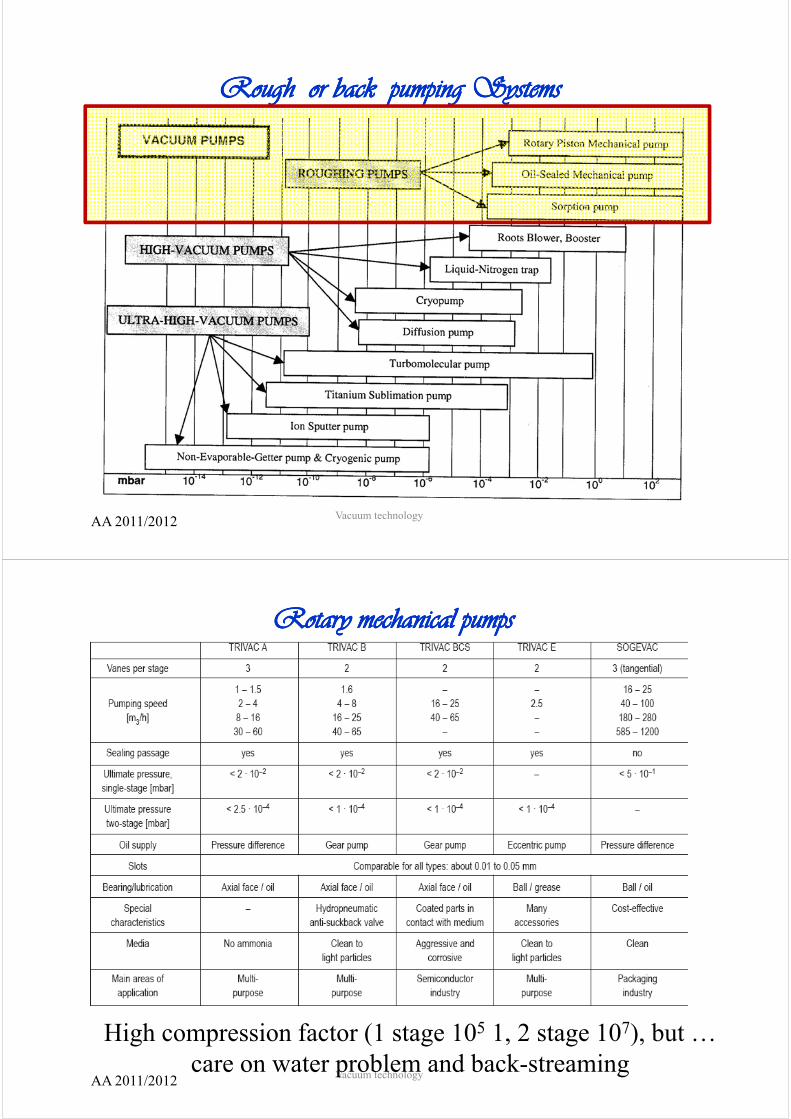
Generation of vacuum (pumps) and measurements Generation of vacuum (pumps) and measurements Generation of vacuum (pumps): ᴥ pumping systems general considerations on their use and “match” with physical quantities introduced for the dimensioning of vacuum systems Vacuum (pressure) measurements: ᴥ vacuum gauges general considerations and use: general considerations and use: – Total pressure gauges, – Partial pressure measurements. AA 2011/2012 Vacuum technology Classification of pump systems: pressure ranges Classification of pump systems: pressure ranges AA 2011/2012 Vacuum technology
Transcript
Generation of vacuum (pumps) and measurementsGeneration of vacuum (pumps) and measurementsG f p pG f p p
Generation of vacuum (pumps):ᴥ pumping systemsp p g y
general considerations on their use and “match” with physical quantities introduced for the dimensioning of vacuum systems
use of the oscillation of a membranes or diaphragms.
• P in system with at least twoPu in system with at least two stage: 1 mbar
• Oil free pumps.
• Available model with teflon protection of volume and parts
exposed to the vacuum for paggressive or corrosive
chemical processes.
AA 2011/2012 Vacuum technology
High vacuum pumping systemsHigh vacuum pumping systems
AA 2011/2012 Vacuum technology
Root BlowersRoot Blowers
There isThere is no oil in the
systems exposedsystems exposedto the vacuum
AA 2011/2012 Vacuum technology
Roots pump CharacteristicsRoots pump CharacteristicsHi h i d L i f t b tHigh pumping speed
Compared with rough pumps Low compression factor but:
If operated properly, the roots compress the oil in the outlet,
then allowing oil free (?) vessel.
AA 2011/2012 Vacuum technology
g ( )Compared with a rough pump,
high speed system and 10 time lower pressure
CryoCryo-- pumpingpumpingyy p p gp p gBased on the principles of
cryocondensation,C tiCryo-sorption,
andCryotrapping:
decreasing the surface temperature of systems exposed to the vacuum
th f dthe processes are favored,depending on the physical and chemical properties of
the gases present in thethe gases present in the vacuum.
At T < 20 K for most
Pgases Pv not higher than 10-11 Torr
At T = 4.2 K H2 gives
AA 2011/2012 Vacuum technology
At T 4.2 K H2 gives
Pv 10-7 Torr
Terms for Terms for cryopumpingcryopumpingCryo-condensation (interaction between molecules): for gases increasing the coverage of a surface a g g gsaturation equilibrium is reached between adsorption and desorption.p
ᴥ Corresponding gas pressure in vacuum: vapor pressure curve p = Q/S + p tpressure curve. p Q/S + psat
Cryo-sorption (interaction of molecules with f ) b l f isurfaces): submonolayer surface coverage experience
attractive van der Waals forces exerted by cold surfaces:
ᴥ as consequence H2 can be cryosorbed at 20 K, and all gases may be cryosorbed at their own boiling temperature (1 bar).
AA 2011/2012 Vacuum technology
atio
nco
nd
ensa
id ( j ) ti ( d ti )kTE
tt
Cry
o-c
residence (sojourn) time (see desorption).kTr ett 0=
rpti
onry
-oso
r
Bi di i ti i 2 3 ti bi f
Cr
AA 2011/2012 Vacuum technology
Binding energy in cryosorption is 2 or 3 times bigger for heavy gases, 10 for H2 and 30 for He.
Conclusions on Conclusions on cryosoprtioncryosoprtiony py p
It may be concluded that at the boiling temperature of N2
(77 K) all gases except He, H2 , D2 and Ne may be(77 K) all gases except He, H2 , D2 and Ne may be cryosorbed.
AA 2011/2012 Vacuum technology
CryotrappingCryotrappingy pp gy pp gCryotrapping is sorption process by which non-condensables
gases are trapped (buried) in the growing solid-liquid gases are trapped (buried) in the growing solid liquid condensation layer of a condensable gas microcrystallites, while
others are incorporated within the crystallites. This method traps non condensable moleculesThis method traps non-condensable molecules.
CryotrappingH H iH2 or He in
N2, or Ar & CO2
AA 2011/2012 Vacuum technology
Back pumprequired for
t tistarting pressure (< 10-3 ) mbar and
regeneration.
Careful use of oil pumps?Poisoning of surfaces byPoisoning of surfaces by
Ti, sublimated in vacuum, reacts with gases and solidifyg y
On colder surfaces trapping the gases.Cooling the surface at lower temperature,
pumping speed increases 2 or 3 order
AA 2011/2012 Vacuum technology
pumping speed increases 2 or 3 order.
Sputter Sputter –– getter ion pumps: getter ion pumps: combine penning process and Ti trapping combine penning process and Ti trapping p g p pp gp g p pp g
Diode
Triode
AA 2011/2012 Vacuum technology
Ion sputter pumpsIon sputter pumpsIon sputter pumpsIon sputter pumps
Diode configuration is better for H2
AA 2011/2012 Vacuum technology
NEG pump (non evaporable getter)NEG pump (non evaporable getter)Chemical reaction. Reactive alloys of zirconium or titanium, configured in cartridge.y g g
Active gases (O2, N2, H2O, CO, CO2) impinging on the cartridge surface are dissociated and permanently trapped, in the form of stable chemical compounds. Also hydrogen is very effectively pumped. Hydrogen (and its isotopes) atoms diffuse y g y y p p y g ( p )inside the getter bulk and dissolve as a solid solution. Noble gases (and CH4 at room temperature) are not pumped.
AA 2011/2012 Vacuum technology
Vacuum monitoring and control Vacuum monitoring and control
AA 2011/2012 Vacuum technology
Vacuum GaugesVacuum Gauges
Direct measurements
Indirect measurements
AA 2011/2012 Vacuum technology
Direct measurementsDirect measurementsCapacitance Manometer
Baratron
Piezo
Membranovac
Diaphragm:
– High precision commercialHigh precision commercial gauges 0.15.%
» 1100 ‐10‐1 mbar
» 110 10‐2» 110 – 10‐2
» 11 ‐ 10‐3
» 1.1 ‐ 10‐4
» 0.11 ‐ 10‐5
It measures the capacitance variaton due do the deformation of a wall (diaphragm).f th l t di l t f 10 9 th l t bilit i d
AA 2011/2012 Vacuum technology
for the lowest pressure range displacement of 10-9 cm: thermal stability required.
Thermal conductivity gauge Heat transfer depends on P, linear dependence for 0.01< Kn <10. )(2
2 pd
kT
πλ =
High PressureLow pressure)( pπ
leaks thermal
)( 41
421
+−= TTAH σε
H t t f d d P if T d d ti t t t
AA 2011/2012 Vacuum technology
Heat transfer depends on P if T and accomodation parameters are constants.
PiraniPirani Gauge Gauge Thermal conductivity gauge, with a Withstone bridge for a higher sensitivity.
Let’s start at a given P with the Vacuum l
gbalanced bridge, if P increases, T of the filament R2 decreases (due to a higher heat exchange), the
vessel
to a higher heat exchange), the bridge is unbalanced.
We can feed more current to keep T =cost (method)
Compensating tube is used f ifor zeroing
at a P < 10-4 mbar.
Thermal conductivity dependes on the gas,
AA 2011/2012 Vacuum technology
y p g ,
the read-out is calibrated for N2.
If R1 R4 = R2R3, then IM = 0
T constant method: R ↓ if P ↑ therefore V (or V=I ) ↑ then → T ↑ )R2 ↓ if P ↑ , therefore Vdc (or V=Idc) ↑ then → T ↑ )
Accuracy 10%, in the range of ccu acy 0%, t e a ge omore sensitivity, more or less for pressure in the range:
10-2 ÷102 mbar10 2 ÷102 mbar
AA 2011/2012 Vacuum technology
Thermocouple gaugesThermocouple gauges
Thermocouple gauges also rely on the dependence of P on the
heat transfer.
Constant Current on a filament on which center f
a thermocouple si soldered.
Therefore from the measurementTherefore from the measurement of the T is possible to provide a
measurement of P.
Accuracy 30%.
AA 2011/2012 Vacuum technology
UHV gauges: UHV gauges: ioniz tion u esioniz tion u es
In HV & UHV the particle density is so low , that it is non
ionization gaugesionization gauges
possible to detect the force exerted on a surface from the molecule impinging on it or the heat transfer.
Hot Cathode gauge
It esploit the ionization of gas by electron bombardment and collection of the positive ion produced in the vacuum vesselp p
The positive ion current collected is proportional to the density of particles in the vacuum vessel, to the electron current and to the ionization cross-section.
AA 2011/2012 Vacuum technology
Hot cathode ionization gaugesHot cathode ionization gauges
Bombarding e- : ie
AA 2011/2012 Vacuum technology
Positive ion current i+=ip collected:
PiSi ep ⋅⋅=ie electron bombardment current, P pressure, S sensitivity (depends on
P(x) to be measured ( ) ( )( ) ( )2
2 NPxS
NSxP =
ionization cross-section), Fixing S for nitrogen to 1.
By the electron excitation of molecule we have also fragmantation effects:
F i ki f H O
AA 2011/2012 Vacuum technology
Fragmantation-cracking pattern for H2O
Cracking pattern and isotopesCracking pattern and isotopesxxx/yyy:
xxx M(amu),yyy: relative abundance.
Max is 100
Isotopic abundance
AA 2011/2012 Vacuum technology
Mass Spectra parent and sonsMass Spectra parent and sons
AA 2011/2012 Vacuum technology
Air mass spectrumAir mass spectrum
AA 2011/2012 Vacuum technology
Ion Detection Ion Detection a) Faraday Cup
and and b) Secondary Electron Multiplier
AA 2011/2012 Vacuum technology
AA 2011/2012 Vacuum technology
ion
AA 2011/2012 Vacuum technology
Or in other words sensitivity of detection Or in other words sensitivity of detection Or in other words, sensitivity of detection Or in other words, sensitivity of detection