36
Generator 300 System User Manual * *Formerly known as ULTRACISION ® HARMONIC SCALPEL ®

Generator 300 System User Manual
*
*Formerly known as ULTRACISION ® HARMONIC SCALPEL®


GEN04
Table of Contents
Chapter 1 – General Information . . . . . . . . . . . . . . . . . . . . . . . . . . . . . . . . . . . . . . . . . . . . . . . . . . . . . . . . . 1Indications . . . . . . . . . . . . . . . . . . . . . . . . . . . . . . . . . . . . . . . . . . . . . . . . . . . . . . . . . . . . . . . . . . . 1Contraindications . . . . . . . . . . . . . . . . . . . . . . . . . . . . . . . . . . . . . . . . . . . . . . . . . . . . . . . . . . . . . 1
Chapter 2 – Principles of Operation . . . . . . . . . . . . . . . . . . . . . . . . . . . . . . . . . . . . . . . . . . . . . . . . . . . . . . 3System Components . . . . . . . . . . . . . . . . . . . . . . . . . . . . . . . . . . . . . . . . . . . . . . . . . . . . . . . . . . . 3
Generator 300 . . . . . . . . . . . . . . . . . . . . . . . . . . . . . . . . . . . . . . . . . . . . . . . . . . . . . . . . . . . . 3Hand Piece . . . . . . . . . . . . . . . . . . . . . . . . . . . . . . . . . . . . . . . . . . . . . . . . . . . . . . . . . . . . . . 3Instrument . . . . . . . . . . . . . . . . . . . . . . . . . . . . . . . . . . . . . . . . . . . . . . . . . . . . . . . . . . . . . . . 3
Power Levels . . . . . . . . . . . . . . . . . . . . . . . . . . . . . . . . . . . . . . . . . . . . . . . . . . . . . . . . . . . . . . . . . 3Controls, Indicators, and Connections . . . . . . . . . . . . . . . . . . . . . . . . . . . . . . . . . . . . . . . . . . . . . 4Unpacking Instructions . . . . . . . . . . . . . . . . . . . . . . . . . . . . . . . . . . . . . . . . . . . . . . . . . . . . . . . . . 6
Chapter 3 – System Setup and Operation . . . . . . . . . . . . . . . . . . . . . . . . . . . . . . . . . . . . . . . . . . . . . . . . 7System Startup . . . . . . . . . . . . . . . . . . . . . . . . . . . . . . . . . . . . . . . . . . . . . . . . . . . . . . . . . . . . . . . 7System Operation . . . . . . . . . . . . . . . . . . . . . . . . . . . . . . . . . . . . . . . . . . . . . . . . . . . . . . . . . . . . . 9System Shutdown . . . . . . . . . . . . . . . . . . . . . . . . . . . . . . . . . . . . . . . . . . . . . . . . . . . . . . . . . . . . 10
Chapter 4 – Troubleshooting . . . . . . . . . . . . . . . . . . . . . . . . . . . . . . . . . . . . . . . . . . . . . . . . . . . . . . . . . . . . 11Audible Indicators and Alarms . . . . . . . . . . . . . . . . . . . . . . . . . . . . . . . . . . . . . . . . . . . . . . . . . . 11Error Codes . . . . . . . . . . . . . . . . . . . . . . . . . . . . . . . . . . . . . . . . . . . . . . . . . . . . . . . . . . . . . . . . 11
Chapter 5 – Cleaning and Disinfection . . . . . . . . . . . . . . . . . . . . . . . . . . . . . . . . . . . . . . . . . . . . . . . . . . 17Generator and Cart Cleaning . . . . . . . . . . . . . . . . . . . . . . . . . . . . . . . . . . . . . . . . . . . . . . . . . . 17Foot Switch Cleaning . . . . . . . . . . . . . . . . . . . . . . . . . . . . . . . . . . . . . . . . . . . . . . . . . . . . . . . . . 17
Chapter 6 – Safety and Function Testing . . . . . . . . . . . . . . . . . . . . . . . . . . . . . . . . . . . . . . . . . . . . . . . . 19Safety Test . . . . . . . . . . . . . . . . . . . . . . . . . . . . . . . . . . . . . . . . . . . . . . . . . . . . . . . . . . . . . . . . . . 19Function Test . . . . . . . . . . . . . . . . . . . . . . . . . . . . . . . . . . . . . . . . . . . . . . . . . . . . . . . . . . . . . . . . 19Calibration . . . . . . . . . . . . . . . . . . . . . . . . . . . . . . . . . . . . . . . . . . . . . . . . . . . . . . . . . . . . . . . . . 19
Chapter 7 – Warnings and Precautions . . . . . . . . . . . . . . . . . . . . . . . . . . . . . . . . . . . . . . . . . . . . . . . . . 21System Warnings and Precautions . . . . . . . . . . . . . . . . . . . . . . . . . . . . . . . . . . . . . . . . . . . . . . . 21Instrument Warnings and Precautions . . . . . . . . . . . . . . . . . . . . . . . . . . . . . . . . . . . . . . . . . . . . 22
Chapter 8 – System Specifications . . . . . . . . . . . . . . . . . . . . . . . . . . . . . . . . . . . . . . . . . . . . . . . . . . . . . . 23Chapter 9 – Warranty . . . . . . . . . . . . . . . . . . . . . . . . . . . . . . . . . . . . . . . . . . . . . . . . . . . . . . . . . . . . . . . . . . 25Chapter 10 – Symbols . . . . . . . . . . . . . . . . . . . . . . . . . . . . . . . . . . . . . . . . . . . . . . . . . . . . . . . . . . . . . . . . . . . 27


Please read all information carefully.
Failure to properly follow the instructions may lead to serious surgical consequences.
Important: The HARMONIC™ Generator 300 System User Manual is designed to provide instructions for use of the HARMONIC
Generator 300, Foot Switch, and Cart (see Chapter 8 – System Specifications for applicable product codes). This manual is not areference to surgical techniques.
Note: Refer to package inserts provided separately for information about the Hand Piece, Hand Switching Adaptor, Adaptors,Test Tip and Instruments prior to using the system.
IndicationsThe HARMONIC System is indicated for soft tissue incisions when bleeding control and minimal thermalinjury are desired. The HARMONIC System instruments can be used as an adjunct to or substitute forelectrosurgery, lasers, and steel scalpels.
Contraindications• The instruments are not indicated for incising bone.• The instruments are not intended for contraceptive tubal occlusion.
Chapter 1 – General Information
1GEN04

User Manual
2 GEN04
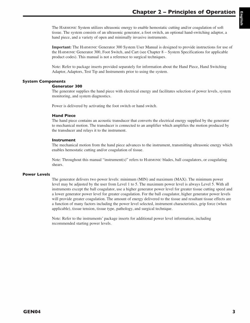
The HARMONIC System utilizes ultrasonic energy to enable hemostatic cutting and/or coagulation of softtissue. The system consists of an ultrasonic generator, a foot switch, an optional hand-switching adaptor, ahand piece, and a variety of open and minimally invasive instruments.
Important: The HARMONIC Generator 300 System User Manual is designed to provide instructions for use ofthe HARMONIC Generator 300, Foot Switch, and Cart (see Chapter 8 – System Specifications for applicableproduct codes). This manual is not a reference to surgical techniques.
Note: Refer to package inserts provided separately for information about the Hand Piece, Hand SwitchingAdaptor, Adaptors, Test Tip and Instruments prior to using the system.
System ComponentsGenerator 300The generator supplies the hand piece with electrical energy and facilitates selection of power levels, systemmonitoring, and system diagnostics.
Power is delivered by activating the foot switch or hand switch.
Hand PieceThe hand piece contains an acoustic transducer that converts the electrical energy supplied by the generatorto mechanical motion. The transducer is connected to an amplifier which amplifies the motion produced bythe transducer and relays it to the instrument.
InstrumentThe mechanical motion from the hand piece advances to the instrument, transmitting ultrasonic energy whichenables hemostatic cutting and/or coagulation of tissue.
Note: Throughout this manual “instrument(s)” refers to HARMONIC blades, ball coagulators, or coagulatingshears.
Power LevelsThe generator delivers two power levels: minimum (MIN) and maximum (MAX). The minimum powerlevel may be adjusted by the user from Level 1 to 5. The maximum power level is always Level 5. With allinstruments except the ball coagulator, use a higher generator power level for greater tissue cutting speed anda lower generator power level for greater coagulation. For the ball coagulator, higher generator power levelswill provide greater coagulation. The amount of energy delivered to the tissue and resultant tissue effects area function of many factors including the power level selected, instrument characteristics, grip force (whenapplicable), tissue tension, tissue type, pathology, and surgical technique.
Note: Refer to the instruments’ package inserts for additional power level information, includingrecommended starting power levels.
Chapter 2 – Principles of Operation
3GEN04

User Manual
4 GEN04
Controls, Indicators, and Connections
Fig. 2-1 Front Panel
1 READY When this indicator is green, the system is ready for activation.
2 STANDBY Push this button to toggle between Standby and Ready modes. In Standby mode,this button, and the STANDBY icon, light up and all power is removed from thehand piece. Both the foot switch and hand switch are disabled. Upon power-up, thesystem defaults to Standby mode enabled.
3 INCREASE/ Push this button to increase or decrease the minimum (MIN) powerDECREASE POWER setting to the desired level (from 1 to 5). The level chosen will be shown on theLEVEL graphic display. The power level may be adjusted when the generator is in Ready or
Standby mode.
4 POWER This switch controls the main electrical power to the generator.
5 VOLUME Turn this knob to adjust the volume of the activation tones. A tone will soundindicating the volume level selected.
6 MIN Indicates the user-settable minimum power level setting. When this power level isactivated (by foot switch or hand switch), the “MIN” indicator will flash. Thesystem defaults to “MIN” power level 3. Refer to the instruments’ package insertsfor the recommended minimum power level.
7 MAX Indicates the maximum power level setting. This setting is always “5”. When thispower level is activated (by foot switch or hand switch), the “MAX” indicatorwill flash.
8 ALARM INDICATOR This red indicator appears only if a system alarm occurs in response to a componentor generator problem.

9 HAND PIECE This receptacle is used to connect the hand piece to the generator.RECEPTACLE
10 HAND ACTIVATION When the indicator is green, hand activation on the hand switching adaptor isenabled. To disable the Hand Activation mode, depress the button. Upon power-up,the system defaults to Hand Activation mode disabled.
Note: If the foot switch is installed, the foot switch is always enabled.
11 TEST Depressing this button initiates the Test mode. This mode is used duringtroubleshooting. The generator will emit a tone when the Test mode is active and“TEST IN PROGRESS” will appear on the display.
12 GRAPHIC DISPLAY In Ready or Standby modes, this display indicates the minimum (user-settablelevel 1 to 5) and maximum (level 5) power levels. If a system or componentproblem exists, error codes will appear on this display.
Fig. 2-2 Back Panel
13 FOOT SWITCH Identical receptacles allow connection of up to two foot switches forRECEPTACLES user convenience. If only one foot switch is used, connect to either receptacle.
14 POTENTIAL This terminal provides a means for connection to a Potential EqualizationEQUALIZATION Conductor.TERMINAL
15 FUSES See the HARMONIC Generator 300 Service Manual for additional information.
16 POWER CORD This receptacle is used to attach the power cord to the generator. For power cordRECEPTACLE requirements, see Chapter 8 – System Specifications.
AUDIBLE SIGNALS The generator delivers audible tones to signal activation and alarm states. The usermay choose from three activation tone pitches. See Chapter 3 – System Setup andOperation for tone selection information. Upon power-up, the system defaults to thelast tone chosen (the mid-pitch tone is factory-set).
Chapter 2 – Principles of Operation
5GEN04
T3.15H 250V
13 14 15
16
6,678,6216,908,472
Covered by one or more of the following US Patents

GEN04
User Manual
6
Unpacking Instructions
The HARMONIC Generator 300 System includes several components that are purchased separately. Uponreceiving the ordered components, check for visible shipping damage. If damage is seen, contact yourEthicon Endo-Surgery representative.
System components may include the following parts (for product codes, see Chapter 8 – SystemSpecifications):
Generator 300 – includes the generator, power cord, user manual, and service manual.
Note: The User Manual includes a troubleshooting guide (see back pocket of manual binder). Remove theself-adhesive guide’s backing and adhere the guide to the top panel of the generator. Placement guides for theTroubleshooting Guide are found on the generator’s top panel.
Foot Switch – includes the foot switch and detachable cable assembly.
Note: The foot switch is required if the system will be used with coagulating shears or instruments withoutthe hand switching adaptor. Since the generator has receptacles for two foot switches, two foot switches mayhave been shipped.
Cart – the cart is optional. It is designed to hold one HARMONIC Generator. The cart requires assembly;instructions are included with the cart.

System Startup
Warning: Products manufactured or distributed by companies other than Ethicon Endo-Surgery may not becompatible with the HARMONIC System. Use of such products may lead to unanticipated results and possibleinjury to the user or patient.
Caution: The HARMONIC system includes components that are shipped non-sterile (e.g. hand piece, handswitching adaptor, adaptors, and blade wrench). Sterilize products as required before beginning system setup.Refer to individual package inserts for cleaning and sterilization instructions.
1 Confirm that the generator power switch is off during setup.
2 Secure the generator on its cart or on another suitable fixture. To secure the generator on itscart, place the generator’s rubber feet into the corresponding holes on the cart. Push down onthe generator’s top panel.
Caution: To prevent overheating during use, ensure that the air vents found on thegenerator’s bottom and back panels are not blocked and that they allow adequate clearancefrom obstructions to allow air to flow freely through the generator enclosure. Avoid placingthe generator on a soft surface. Warning: The HARMONIC system must be operated within the required ambient operatingconditions. Refer to Chapter 8 – System Specifications for requirements.Caution: Do not simultaneously touch the patient and generator.
3 Connect the line cord into the AC inlet located on the generator’s rear panel and into anappropriately-grounded outlet. If the power cord is wrapped around the cart handle, it mustbe completely removed from the cart handle prior to plugging it into the power outlet.
Warning: Verify that the outlet voltage correctly corresponds to the generator’srequirements (see Chapter 8 – System Specifications). Connection to an improper powersupply may result in damage to the generator and risk of shock or fire hazard.
4 a. Attach the foot switch cable to the foot switch:
Note: Although installation of the foot switch is optional when using the hand switchingadaptor, installing the foot switch is recommended in case its use is needed during theprocedure.
• Confirm that the connector and receptacle are dry and clean.• Orient the slot on the foot switch cable’s larger connector at 12 o’clock.• Seat the connector in the foot switch receptacle.• Turn the connector collar clockwise until tight. Ensure the collar is finger-tight to
prevent inadvertent activation because of fluid ingress.
b. Connect the foot switch cable’s smaller connector to the foot switch receptacle on the rearpanel of the generator. • Confirm that the connector and receptacle are dry and clean.• Align the red dot on the foot switch 4-pin connector with the red dot on the 4-pin
receptacle on the generator back panel.
Note: The generator has two identical foot switch receptacles. If one foot switch is used,either receptacle may be used.
Repeat steps 4a and 4b if a second foot switch will be used.
Chapter 3 – System Setup and Operation
7GEN04

5 Connect the instrument and adaptor (or hand switching adaptor), if required, to the handpiece following instructions in their package inserts.Note: The hand switching adaptor must be at room temperature to function properly. Do notimmerse in water to cool rapidly. After steam sterilization, allow hand switching adaptor toair cool for at least 15 minutes prior to use.
6 Connect the hand piece connector to the receptacle on the front panel. Align the white dot onthe connector with the white dot on the generator. Ensure the hand piece connector is cleanand dry before connecting the hand piece to the generator. Fully insert the hand piececonnector to assure complete, proper connection to the generator.
7 Turn the generator power switch on and observe the power-up sequence. During power-up,the following indicators on the front panel will briefly illuminate:• READY, STANDBY, MIN, MAX, TEST, ATTENTION, HAND ACTIVATION
The system will run its start-up sequence and display the software version. An audible tonewill sound during the initiation sequence.Note: The entire power-up initiation sequence should not exceed ten seconds.
If the start-up sequence deviates from the description above, contact qualified service personnelfollowing hospital protocol.
When the initiation sequence is complete, the system will go to Standby. However, if the systemdetects a faulty generator or incorrect hand piece, a fault will appear on the graphic display (thepower levels will not be visible) and an audible alarm will sound. Refer to Chapter 4 –Troubleshooting or the Troubleshooting Guide.
8 Power Levels: Upon startup, the generator defaults to power level 3 (MIN) and 5 (MAX).The minimum (MIN) power level is user-settable from power levels 1 to 5. To adjust thepower level, depress the up/down arrow button to the left of the minimum power leveldisplay. Set the power level based on surgeon preference and/or recommendations providedin the instrument’s package insert (for more information, see Power Levels section inChapter 2 – Principles of Operation).
9 Audible tones: The generator has three activation tone sets from which to choose (the mid-pitch tone is factory set). To choose another tone: a. Switch power off.b. Switch power on. Then immediately depress and hold both the STANDBY and HANDACTIVATION buttons. When the graphic shown in Figure 3-1 appears on the display,release the STANDBY and HAND ACTIVATION buttons.c. While in the Tone Selection mode, the generator will automatically sequence through theavailable tone pitches. To select a tone, depress any button on the control panel. Thegenerator will return to Standby mode. The tone chosen will be saved until it is changedagain by accessing the Tone Selection mode.
Fig. 3-1 Tone Selection Display
Adjust tone volume by turning the knob on the lower left corner of the control panel. Atone will sound to indicate the volume level selected. For safety reasons, the tone may notbe disabled.
User Manual
8 GEN04
System OperationImportant: The HARMONIC Generator 300 System User Manual is designed to provide instructionsfor use of the HARMONIC Generator 300, Foot Switch, and Cart (see Chapter 8 – SystemSpecifications for applicable product codes). This manual is not a reference to surgical techniques.
Note: Refer to package inserts provided separately for information about the Hand Piece, HandSwitching Adaptor, Adaptors, Test Tip and Instruments prior to using the system.
After completing system setup, the system may be operated.
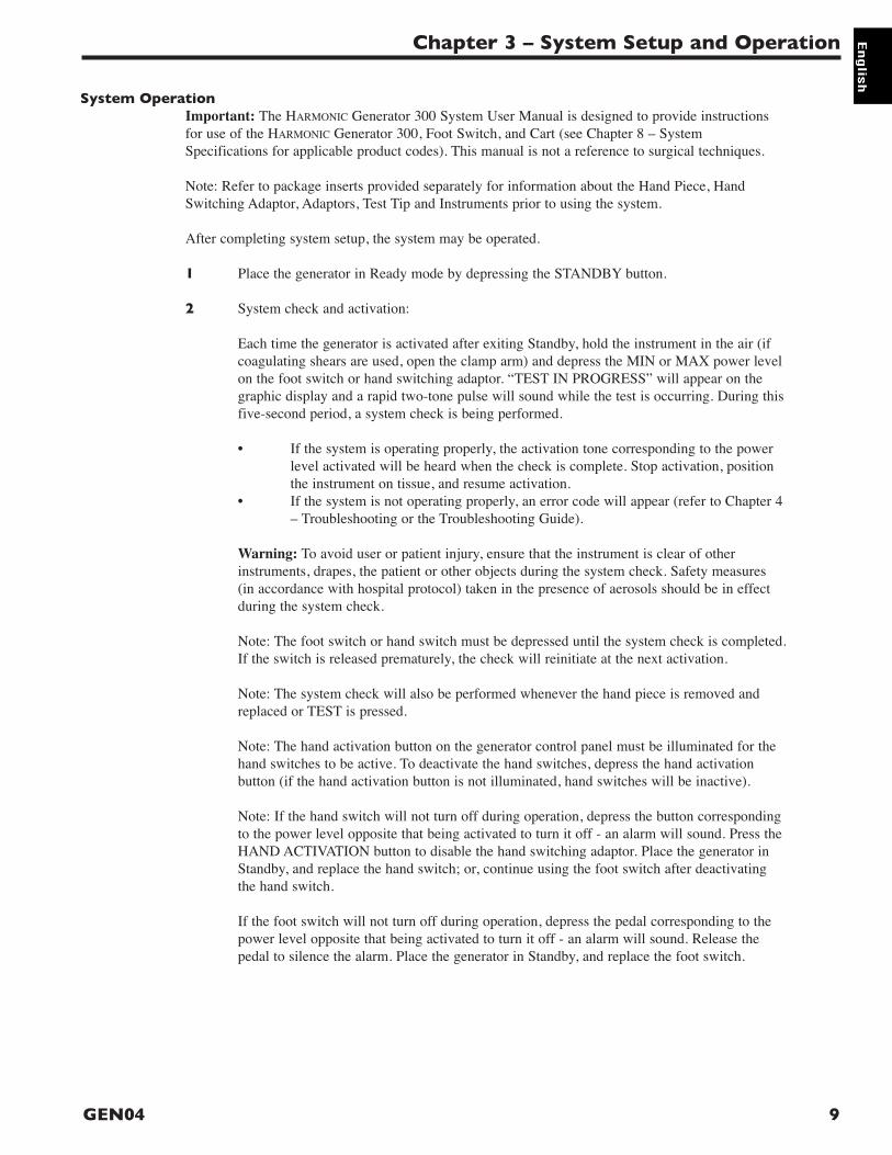
1 Place the generator in Ready mode by depressing the STANDBY button.
2 System check and activation:
Each time the generator is activated after exiting Standby, hold the instrument in the air (ifcoagulating shears are used, open the clamp arm) and depress the MIN or MAX power levelon the foot switch or hand switching adaptor. “TEST IN PROGRESS” will appear on thegraphic display and a rapid two-tone pulse will sound while the test is occurring. During thisfive-second period, a system check is being performed.
• If the system is operating properly, the activation tone corresponding to the powerlevel activated will be heard when the check is complete. Stop activation, positionthe instrument on tissue, and resume activation.
• If the system is not operating properly, an error code will appear (refer to Chapter 4– Troubleshooting or the Troubleshooting Guide).
Warning: To avoid user or patient injury, ensure that the instrument is clear of otherinstruments, drapes, the patient or other objects during the system check. Safety measures(in accordance with hospital protocol) taken in the presence of aerosols should be in effectduring the system check.
Note: The foot switch or hand switch must be depressed until the system check is completed.If the switch is released prematurely, the check will reinitiate at the next activation.
Note: The system check will also be performed whenever the hand piece is removed andreplaced or TEST is pressed.
Note: The hand activation button on the generator control panel must be illuminated for thehand switches to be active. To deactivate the hand switches, depress the hand activationbutton (if the hand activation button is not illuminated, hand switches will be inactive).
Note: If the hand switch will not turn off during operation, depress the button correspondingto the power level opposite that being activated to turn it off - an alarm will sound. Press theHAND ACTIVATION button to disable the hand switching adaptor. Place the generator inStandby, and replace the hand switch; or, continue using the foot switch after deactivatingthe hand switch.
If the foot switch will not turn off during operation, depress the pedal corresponding to thepower level opposite that being activated to turn it off - an alarm will sound. Release thepedal to silence the alarm. Place the generator in Standby, and replace the foot switch.
Chapter 3 – System Setup and Operation
9GEN04
3 If the system senses a generator, hand piece, or instrument fault during use, an audible alarm(tone with long pulses) will sound and a visual alarm indicator will appear on the controlpanel. (Refer to Chapter 4 – Troubleshooting or the Troubleshooting Guide to resolve theproblem.)
Warning: Place the generator in Standby mode before removing or replacing an instrument,hand switching adaptor or hand piece or when the system is not in use.
System Shutdown1 Turn the generator power switch off and remove power cord from outlet.
2 Disconnect the hand piece, instrument, and adaptor or hand switching adaptor (if used) andprocess them as indicated in their respective package inserts.
3 Clean the generator and cart and disinfect the foot switch(es) following hospital protocol (forrecommendations, refer to Chapter 5 – Cleaning and Disinfection).
4 Store foot switch(es) on the cart shelves provided. Each shelf will hold one foot switch.
5 Wrap foot switch cable(s) and the power cord on the cart’s back handle for storage.
User Manual
10 GEN04

The Generator 300 System supports a series of alarms and error codes to help in the identification andtroubleshooting of component problems. These guides are meant as an adjunct to, but not a substitute for,clinical judgment and observations.
Audible Indicators and Alarms
Tone Possible Cause and Corrective ActionNo tone when system is activated. Confirm foot switch is fully connected (if hand switch is not
being used).
Confirm foot switch is not faulty.
If hand switch is used, confirm it is connected and not faulty.
Confirm hand activation is enabled if hand switching adaptor isbeing used.
Activation (brief pulses) System is being activated or is in Test mode. System is operatingproperly. MIN and MAX power have unique tones.
Alert (three-tone sequence) Activation is attempted while generator is in Standby mode. Push theSTANDBY button to return the generator to Ready mode.
Two or more foot or hand switches are recognized by the generator asbeing activated simultaneously. Reactivate using only one switch.
Constant tone 1) Instrument is in contact with too much tissue. Reduce the amount oftissue in contact with the instrument. If tone persists, carefully removeany tissue that has collected in the distal end of the instrument shaft. 2) Hand piece and/or blade fault. Press TEST to identify source of fault.
Prolonged solid tone during Hand piece and/or blade fault. Press TEST to identify source of fault.activation (exceeds 10 seconds)
Alarm (two-tone sequence) A component or system problem has occurred. Refer to the ErrorCodes section in this chapter or the Troubleshooting Guide.
Note: This alarm will activate for three seconds, then will silence itselffor 30 seconds. This cycle will continue until the error is resolved orthe main power switch is turned off.
Error CodesThe generator will recognize specific faults in five areas: generator, hand piece, instrument, foot switch orhand switch. When a fault is identified, an alarm will sound, the alarm indicator will appear on the generatorcontrol panel, and the source of the problem will appear on the graphic display (the power levels will not bedisplayed). See Fig. 4-1 below for an example. Follow the procedures outlined below (or in theTroubleshooting Guide) to resolve the problem.
Fig. 4-1 Alarm Indicator (example)
Chapter 4 – Troubleshooting
11GEN04

GEN04
User Manual
12
Error Code 1: Generator Error Code 1 indicates either there is a functional problem with thegenerator or the front panel button(s) were activated during power-upsequence.Cycle the power OFF then ON. If error persists, power off system andcontact service.
Error Code 2: Generator Error Code 2 indicates that the generator is overheating.Temperature
1 Power off system. Remove any obstructions blocking the airvents on the generator’s bottom and back panels. If there is noapparent obstruction or external heat source, contact service.
2 Power on the system and wait for up to 30 minutes for generatorerror to clear.
3 If error code persists, contact service.
Error Code 3: Hand Piece Error Code 3 indicates a problem with the hand piece.
1 Confirm that the hand piece connector is fully inserted andproperly oriented – white dot on handpiece is aligned with whitedot on front panel. If the error code does not clear within threeseconds after the hand piece is properly connected, press TEST.
2 The instrument may not be tightened properly or tissue mayhave collected in the distal end of the instrument shaft. Tighteninstrument using blade wrench and carefully remove tissue fromdistal end of instrument sheath. Press STANDBY to clear errorcode and return to Ready mode. Activate system. If the pre-runtest is running, ensure instrument is in air. If using shears, ensurejaws are open and not in contact with any objects during pre-run test.
Note: Inspect the blade wrench hub for cracks or wear before use. Ifdamage is seen, replace the blade wrench. Before use afterautoclaving, cool the blade wrench at room temperature for at least 45minutes or soak it in room temperature sterile water for 5 minutes.
3 If the error persists, install a test tip to isolate the problem. PressTEST button.- If system indicates a hand piece error, hand piece is bad or
test tip is bad. Replace hand piece or install a new test tipand press TEST.
- If no error occurs with test tip attached, replace instrument.
4 Press STANDBY to return to Ready mode. Activate system.
Error Code 4: Hand Piece Error Code 4 indicates that the hand piece has exceeded itsTemperature specified operating temperature. For immediate recovery, use another
hand piece; or, follow the steps below to determine the cause of theerror condition and alternate recovery methods.

The following are possible causes of an increase in hand piecetemperature. To correct, complete the appropriate steps below andallow the hand piece to cool before resuming operation.
1 The hand piece is still warm from recent steam sterilization.Allow the hand piece to cool at room temperature for at least 45minutes or soak it in room-temperature sterile water for 5minutes before resuming operation.
Note: The hand switching adaptor (HSA07) should not be submergedfor rapid cooling purposes. This may render the hand switchingadaptor inoperable for an extended period of time. After steamsterilization, allow the hand switching adaptor to air cool at least15 minutes prior to use.
2 The instrument may not be tightened properly or tissue mayhave collected in the distal end of the instrument shaft. Tighteninstrument using blade wrench and carefully remove tissue fromdistal end of instrument sheath. Press STANDBY to clear errorcode and return to Ready mode. Activate system. If the pre-runtest is running, ensure instrument is in air. If using shears, ensurejaws are open and not in contact with any objects during pre-run test.
Note: Inspect the blade wrench hub for cracks or wear before use. Ifdamage is seen, replace the blade wrench. Before use afterautoclaving, cool the blade wrench at room temperature for at least 45minutes or soak it in room temperature sterile water for 5 minutes.
3 If the error persists, install a test tip to isolate the problem. PressTEST button.- If system indicates a hand piece error, hand piece is bad or
test tip is bad. Replace hand piece or install a new test tipand press TEST.
- If no error occurs with test tip attached, replace instrument.
4 Press STANDBY to return to Ready mode. Activate system.
5 If the hand piece does not show evidence of overheating andtroubleshooting steps 1-4 above do not appear to resolve theproblem, perform the following:
a. Leave the hand piece at room temperature for 24 hours ormore.b. Remove any test tip or instrument from the hand piece.c. With the generator turned off, plug the hand piece into anyGenerator 300.d. Power up the generator in Biomed mode.- Press and hold down the STANDBY button and down
arrow key.- Wait for a steady display – approximately 10 seconds.- If a “Generator” error occurs, then one of the buttons was
not properly held down. If this happens, repeat the power upprocedure in Biomed mode.
Chapter 4 – Troubleshooting
13GEN04

e. Record the “XDUCER CAPACITANCE” value.- Press the STANDBY button, if necessary, until
it illuminates. - Use the increase/decrease arrow keys to get to
“Page 2 of 21”.- Record the number opposite “XDUCER CAPACITANCE”.- Press the STANDBY button until the Standby light
turns off.- Leave the hand piece plugged into the generator. Do not
remove hand piece during entire procedure. Do not activatethe MIN or MAX activation buttons on the foot switch orhand switch if either is attached.
- After a period of time that exceeds 30 or more minutes,press the STANDBY button until the STANDBY lightis illuminated.
- Again, read the “XDUCER CAPACITANCE” onPage 2 of 21.
- If the number has changed, the update was successful.- If the number has not changed, then this update attempt did
not succeed. Power down the generator and repeat Step 5.
Note: As the hand piece ages, the generator performs measurementsand updates a key hand piece parameter. This function is performedwhen the internal temperature of the hand piece is stable at roomtemperature. Certain usage patterns may prevent this update fromoccurring and subsequently make the hand piece diagnostics moresensitive to temperature. The steps above will cause an update of thehand piece parameter and return the system to designed sensitivity.
Warning: To avoid user or patient injury, ensure that the instrument isclear of other instruments, drapes, the patient or other objects beforepressing TEST. Safety measures (in accordance with hospital protocol)taken in the presence of aerosols should be in effect while in Test mode.
Note: Do not run the Test mode while an electrosurgical generator isbeing activated in the room. Interference from the electrosurgicalgenerator may affect test results.
Error Code 5: Instrument Error Code 5 indicates a problem with the instrument.
1 The instrument may not be tightened properly or tissue mayhave collected in the distal end of the instrument shaft. Tighteninstrument using blade wrench and carefully remove tissue fromdistal end of instrument sheath. Press STANDBY to clear errorcode and return to Ready mode. Activate system. If the pre-runtest is running, ensure instrument is in air. If using shears,ensure jaws are open and not in contact with any objectsduring pre-run test.
User Manual
14 GEN04

Note: Inspect the blade wrench hub for cracks or wear before use.If damage is seen, replace the blade wrench. Before use afterautoclaving, cool the blade wrench at room temperature for at least45 minutes or soak it in room temperature sterile water for 5 minutes.
2 If the error persists, install a test tip to isolate the problem. PressTEST button.- If system indicates a hand piece error, hand piece is bad or
test tip is bad. Replace hand piece or install a new test tipand press TEST.
- If no error occurs with test tip attached, replace instrument.
3 Press STANDBY to return to Ready mode. Activate system.
Note: Inspect the blade wrench hub for cracks or wear before use.If damage is seen, replace the blade wrench. Before use afterautoclaving, cool the blade wrench at room temperature for at least45 minutes or soak it in room temperature sterile water for 5 minutes.
Warning: To avoid user or patient injury, ensure that the instrumentis clear of other instruments, drapes, the patient, or other interferencebefore pressing TEST. Safety measures (in accordance with hospitalprotocol) taken in the presence of aerosols should be in effect whilein Test mode.
Note: Do not run the Test mode while an electrosurgical generator isbeing activated in the room. Interference from the electrosurgicalgenerator may affect test results.
Error Code 6: Foot Switch Error Code 6 indicates a foot switch pedal is stuck in the ON position.Confirm generator receptacle, foot switch receptacles and cableconnectors are clean and dry or replace the foot switch.Note: If the error persists, replace foot switch.
Error Code 7: Hand Switch Error Code 7 indicates the hand switch is stuck in the ON position.Confirm contacts in the distal end of hand piece and in the proximalend of the hand switching adaptor are dry or replace the handswitching adaptor.Note: If the error persists, replace hand switch.
Chapter 4 – Troubleshooting
15GEN04

User Manual
16 GEN04

Generator and Cart Cleaning
Clean generator and cart following hospital protocol. Before cleaning, turn the generator main power off andunplug the power cord from the grounded electrical outlet.
Warning: Spilling or spraying fluids on or into the generator or immersing the generator may result indamage to the generator and risk of shock or fire hazard.
Proceed with cleaning as follows:1 Prepare a neutral pH detergent or neutral pH enzymatic detergent according to the detergent
manufacturer’s directions.
2 Use a soft, clean cloth lightly moistened with the cleaning solution to manually clean all surfaces(including the generator’s display).
3 Rinse thoroughly using a soft, clean cloth lightly moistened with warm tap water.
4 Dry with a clean, soft cloth.
Foot Switch Cleaning
The foot switch and cable should be cleaned after each use as follows:1 Disconnect the foot switch from the generator.
2 Prepare a neutral pH enzymatic detergent according to the detergent manufacturer’s directions.
3 With the cable securely attached to the foot switch, soak the foot switch and cable in the detergentsolution for two minutes.
Note: Keep the foot switch cable connector that connects to the generator dry at all times to preventinadvertent activation.
4 After soaking, use a soft-bristled brush to manually clean the foot switch and cable keeping themimmersed in the detergent solution.
5 Thoroughly rinse the foot switch and cable – with the cable securely attached to the foot switch – withwarm, running tap water for at least one minute.
6 Dry all surfaces with a clean, soft cloth.
Chapter 5 – Cleaning and Disinfection
17GEN04

User Manual
18 GEN04

Test hand piece, generator, and foot switch for safety and function according to hospital protocol. Refer toindividual package inserts for safety and function testing for other multi-patient use components.
Safety TestGenerator: A qualified hospital technician should perform a leakage current test.
Foot Switch: Examine the foot pedals, cable connectors, and cable for cracks or other damage and replaceif damaged.
Other Components: Examine the components by following the instructions in their individual packageinserts.
Function Test1 Perform complete instrument preparation and hand piece attachment as described in Chapter 3 –
System Setup and Operation. Attach the test tip rather than an instrument.
2 Verify that the orange STANDBY indicator is illuminated.
3 Push the STANDBY button to leave Standby mode and enter Ready mode.
4 Verify that the green READY indicator is illuminated.
5 Verify that MIN Power Level 3 and MAX Power Level 5 are displayed.
6 Push the Increase and Decrease Power Level button up and down to confirm the MIN Power Levelchanges from 1 to 5.
7 Turn the generator off. Wait five seconds, then turn the generator back on. Wait ten seconds, thenconfirm MIN Power Level 3 and MAX Power Level 5 are displayed. Confirm the generator is notbeing activated unexpectedly.
8 Place the generator in Ready mode by depressing the STANDBY button. Hold the hand piece so thatthe distal portion is in the air and step on the MAX foot switch pedal (before activation begins, a five-second system check will be performed – “TEST IN PROGRESS” will appear on the display). Verifythat the MAX Power Level indicator on the control panel flashes and that the MAX activation tone isheard.
Warning: To avoid user injury, ensure that the test tip is clear of tissue, other instruments, or otherobjects before activating the system.
9 Hold the hand piece so that the distal portion is in air and step on the MIN foot switch pedal. Verifythat the MIN Power Level indicator on the control panel flashes and that the MIN activation tone isheard.
Warning: To avoid user injury, ensure that the test tip is clear of tissue, other instruments, or otherobjects before activating the system.
CalibrationRefer to the Generator 300 System Service Manual for system calibration information.
Chapter 6 – Safety and Function Testing
19GEN04

User Manual
20 GEN04

System Warnings and Precautions• Minimally invasive procedures should be performed only by persons having adequate training and
familiarity with minimally invasive techniques. Consult medical literature relative to techniques,complications, and hazards prior to performance of any minimally invasive procedure.
• Minimally invasive instruments may vary from manufacturer to manufacturer. When minimally invasiveinstruments and accessories from different manufacturers are employed together in a procedure, verifycompatibility prior to initiation of the procedure.
• A thorough understanding of the principles and techniques involved in laser, electrosurgical, and ultrasonicprocedures is essential to avoid shock and burn hazards to both patient and medical personnel and damageto the device or other medical instruments. Ensure that electrical insulation or grounding is notcompromised. Do not immerse electrosurgical instruments in liquid unless the instruments are designed andlabeled to be immersed.
• Safe and effective ultrasonic surgery is dependent not only upon equipment design, but also, to a largeextent, upon factors under control of the operator. It is important that the instructions supplied with thisequipment be read, understood, and followed in order to enhance safety and effectiveness.
• As with all energy sources (Electrosurgery, Laser, or Ultrasound), there are concerns about the carcinogenicand infectious potential of the by-products, such as tissue smoke plume and aerosols. Appropriate measuressuch as protective eyewear, filtration masks, and effective smoke evacuation equipment should be used inboth open and laparoscopic procedures.
• To avoid user or patient injury in the event that accidental activation occurs, the HARMONIC instrumentblades should not be in contact with the patient, drapes, or flammable materials while not in use. Duringprolonged activation in tissue, the instrument blade, clamp arm and distal end of the shaft may become hot.Avoid unintended blade contact with tissue, drapes, surgical gowns, or other unintended sites afteractivation.
• To avoid user or patient injury, the HARMONIC Generator should not be used prior to biomedical evaluationif it shows signs of damage or is suspected of being dropped or having fluids spilled on it.
• After removing the instrument, examine the tissue for hemostasis. If hemostasis is not present, appropriatetechniques should be used to achieve hemostasis.
• Products manufactured or distributed by companies other than Ethicon Endo-Surgery may not becompatible with the HARMONIC system. Use of such products may lead to unanticipated results and possibleinjury to the user or patient.
• The HARMONIC system, including the hand piece, is not Magnetic Resonance safe and is not MagneticResonance compatible.
• To reduce the risk of interference, electrosurgical systems and the HARMONIC system should be plugged intoseparate electrical power circuits. Locate the HARMONIC system, including the hand piece cable, at least 3 ft.(approximately 1 m) from electrosurgical systems and their hand piece (e.g., pencil) cables.
• Equipment not suitable for use in the presence of a flammable anesthetic mixture with air or with oxygen ornitrous oxide. It is possible to create sparks by hitting other metal instruments. Sparks may igniteflammable gases such as bowel gas.
• The HARMONIC system must be operated within the required ambient operating conditions. Refer to Chapter8 – System Specifications for requirements.
• To prevent overheating during use, ensure that the air vents found on the generator’s bottom and backpanels are not blocked and that they allow adequate clearance from obstructions to allow air to flow freelythrough the generator enclosure. Avoid placing the generator on a soft surface.
• Verify that the outlet voltage correctly corresponds to the generator’s requirements (see Chapter 8 – SystemSpecifications). Connection to an improper power supply may result in damage to the generator and risk ofshock or fire hazard.
• The HARMONIC system includes components that are shipped non-sterile (e.g. hand piece, hand switchingadaptor, adaptors, and blade wrench). Sterilize products as required before beginning system setup. Refer toindividual package inserts for cleaning and sterilization instructions.
• To avoid user or patient injury, ensure that the instrument is clear of other instruments, drapes, the patient,or other objects before pressing TEST and during the system check. Safety measures (in accordance withhospital protocol) taken in the presence of aerosols should be in effect during the system check and while inTest mode.
Chapter 7 – Warnings and Precautions
21GEN04
• To avoid user injury, ensure that the test tip is clear of tissue, other instruments, or other objects beforeactivating the system.
• Do not simultaneously touch the patient and generator.• Place the generator in the Standby mode before removing or replacing an instrument, hand switching
adaptor or hand piece or when system is not in use.• Spilling or spraying fluids on or into the generator or immersing the generator may result in damage to the
generator and risk of shock or fire hazard.• In case of system failure, ensure the availability of the appropriate backup equipment relevant to the
specific procedure.
Instrument Warnings and Precautions
BladesAll blades have an intermittent operation of 15 second on/off intervals, unless the duty cycle is explicitlyspecified otherwise in the individual instrument package inserts.
Coagulating ShearsDuring prolonged activation in tissue, the instrument blade, clamp arm, and the distal 7 cm of the shaftmay become hot. Avoid unintended contact with tissue, drapes, surgical gowns, or other unintended sitesat all times.
Note: Refer to individual package inserts for additional warnings and precautions.
User Manual
22 GEN04

Product Codes Required Components for System Operation:GEN04: Generator 300HP054/HP055: Hand Piece (includes HST02 Test Tip and TLB01 Blade Wrench)1
Instruments and Adaptors:Contact your Ethicon Endo-Surgery representative for informationabout instruments available for use with this system. Someinstruments may require use of an adaptor.
Optional Components:FSW01: Foot Switch2
HSA07: Hand Switch1,2
CRT01: Cart
1 Refer to separate product insert supplied with this component.2 At a minimum, either the foot switch or the hand switch is requiredto operate the generator. When the hand switch is used, availability ofthe foot switch is recommended.
Degree of Protection Against Electric Shock Type CF Applied Part
Class of Protection Against Electric Shock Class I
Safety Standards EN 60601-1
Degree of Protection Against Harmful Ingressof Water Generator: Ordinary equipment
Footswitch: IPX8
Safety Classification UL 2601-1 CSA C22.2 601.1EN 60601-1
Mains Input Voltage: 100-240 VACFrequency: 50/60 HzCurrent Consumption: 3 amp
Ambient OperatingConditions Temperature 18˚C to 23˚C
Humidity: 10-90% non-condensingAtmospheric Pressure Range: 700hPa-1060hPa
Transport and StorageConditions Temperature: -35˚C to +54˚C
Humidity: 10-95% non-condensingAtmospheric Pressure Range: 700hPa-1060hPa
Chapter 8 – System Specifications
23GEN04

Date of Manufacture The date of manufacture may be determined by viewing the serialnumber on the rear panel of the generator. The fourth and fifthcharacters indicate the year of manufacture as follows:GN401 = year 2001GN402 = year 2002GN403 = year 2003GN404 = year 2004GN405 = year 2005GN406 = year 2006GN407 = year 2007
Power Cord North American removable power cord set with thefollowing characteristics:Plug Style: NEMA 5-15 (clear) North American Hospital GradeReceptacle: IEC 60320 C13 with straight non-angled cord entryCord Length: 4.6 meters nominalCurrent Rating: 13AVoltage Rating: 125 VAC minimumWiring Code: North AmericanCordage Description: SJT (UL) or SJT (CSA)Conductors: 16 AWG 3CAgency Approvals Required: UL and CSA
International removable power cord set with the followingcharacteristics:Plug Style: as needed by particular country requirementsReceptacle: IEC 60320 C13 with straight non-angled cord entryCord Length: 2.44 - 4.6 meters nominalCurrent Rating: 10AMinimum conductor size cross-sectional area: 1.0mm2 copperVoltage Rating: 250 VAC minimumWiring: internationalCordage Type: HARItem to have certification by at least one of the following agencies:VDE,ASTA, SEMKO, KEMA, LCIE, DFT, IMQ, SEV
Duty Cycle Duty Cycle is determined by hand piece and instrument in use. Forduty cycle information, refer to applicable instrument(s) and handpiece inserts and/or Chapter 7 – Warnings and Precautions.
Weight Generator: 7.48 kg nominal(unpacked)
Cart: 42.0 kg nominal
Overall Dimensions Generator 300 (HxWxD): 5.3" (13 cm) x 14.5" (37 cm) x 15.2" (39 cm)
Cart (HxWxD): 37.3" (95 cm) x 17.7" (45 cm) x 27.6" (70 cm),including handle
Disposal Some internal components of the generator, foot switch and footswitch cable contain lead. Disposal should be performed accordingto local requirements and regulations.
User Manual
24 GEN04

GEN04 25
Chapter 9 - Warranty
This warranty and the rights and obligations hereunder shall be construed under and governed by thelaws of the State of Ohio, U.S.A.
Ethicon Endo-Surgery warrants this product to be free from defects in material and workmanship undernormal use and preventive maintenance for the respective warranty period shown below. Ethicon Endo-Surgery’s obligation under this warranty is limited to the repair or replacement, at its option, of anyproduct, or part thereof, which has been returned to Ethicon Endo-Surgery or its Distributor within theapplicable time period shown below and which examination disclosed, to Ethicon Endo-Surgery’ssatisfaction, to be defective. This warranty does not apply to any product, or part thereof, that has been: (1)adversely affected due to use with devices manufactured or distributed by parties not authorized byEthicon Endo-Surgery (2) repaired or altered outside Ethicon Endo-Surgery’s factory in a way so as to, inEthicon Endo-Surgery’s judgement, affect its stability or reliability, (3) subjected to improper use,negligence or accident, or (4) used other than in accordance with the design and use parameters,instructions and guidelines for the product or with functional, operational or environmental standards forsimilar products generally accepted in the industry.
Ethicon Endo-Surgery’s products are warranted for the following periods after delivery to theoriginal purchaser:
Hand Pieces Nine (9) Months, Parts and LaborGenerators One (1) Year, Parts and LaborCarts One (1) Year, Parts and LaborFoot Switches and Cables One (1) Year, Parts and LaborSterilization Tray One (1) Year, Parts and Labor
UNLESS SUPERCEDED BY APPLICABLE LOCAL LAW, THIS WARRANTY IS IN LIEUOF ALL OTHER WARRANTIES, EXPRESS OR IMPLIED, INCLUDING THE WARRANTIESOF MERCHANTABILITY AND FITNESS FOR A PARTICULAR PURPOSE, AND OF ALLOTHER OBLIGATIONS OR LIABILITIES ON THE PART OF ETHICON ENDO-SURGERYAND IS A PURCHASER’S EXCLUSIVE REMEDY. IN NO EVENT SHALL ETHICON ENDO-SURGERY BE LIABLE FOR SPECIAL, INCIDENTAL OR CONSEQUENTIAL DAMAGESINCLUDING, WITHOUT LIMITATION, DAMAGES RESULTING FROM LOSS OF USE,PROFITS, BUSINESS OR GOODWILL, OTHER THAN AS EXPRESSLY PROVIDED BY ASPECIFIC LAW. Ethicon Endo-Surgery neither assumes nor authorizes any other person to assumefor it any other liability in connection with the sale or use of any of Ethicon Endo-Surgery products.There are no warranties that extend beyond the terms hereof.
Ethicon Endo-Surgery reserves the right to make changes to products built and/or sold by them at anytime without incurring any obligation to make the same or similar changes on products previously builtand/or sold by them.

User Manual
26 GEN04

On
Off
Type CF Applied Part
Lot
Temperature
Relative Humidity
Attention - Consult AccompanyingDocuments/See Instructions For Use
Non-Sterile
Date of Manufacture
Fragile
This end up
Keep dry
Increase/Decrease
Serial Number
Equipotential
Chapter 10 – Symbols
27GEN04
Fuse
Safe working load
Test
Hand Activation
Volume
Minimum
Maximum
Ready
Standby
Reorder Number
Caution: Federal (USA) law restricts this deviceto sale by or on the order of a physician.
ON/OFF Time for Intermittent Operation.Refer to the individual package insert and/orChapter 7 – Warnings and Precautions foradditional specifications.
Foot switch
Category AP (Anaesthetic Proof) Equipment

Manufacturer
Authorized Representative in the European Community
Authorized Representative in the USA
Electrical and electronic equipment. Return waste to a collection system or treatment and recycling facilities.
Applicable in the EU. Follow decontamination instructions before returning waste.
User Manual
28 GEN04


32 GEN04
REF
GEN04
Ethicon Endo-Surgery (Europe) GmbHHummelsbuetteler Steindamm 7122851 NorderstedtGERMANY
Johnson & Johnson AGCH-8957 SpreitenbachSWITZERLAND
ETHICON ENDO-SURGERY, INC.Cincinnati, OH 45242-2839 USA1-800-USE-ENDO
P40361P05
P40361P05


