+ All Categories
Home > Documents > Generator Automatic Voltage Regulator Operation Manual · Generator Automatic Voltage Regulator ......

Generator Automatic Voltage Regulator Operation Manual · Generator Automatic Voltage Regulator ......

Date post: 25-May-2018
Category:
Upload: nguyenkhuong
View: 253 times
Download: 0 times
Share this document with a friend
13
Headquarters : No.3, Lane 201, Chien Fu St., Chyan Jenn Dist., Kaohsiung, TAIWAN Tel : + 886-7-8121771 Fax : + 886-7-8121775 URL : http://www.kutai.com.tw EA150 Generator Automatic Voltage Regulator Operation Manual Self Excited Automatic Voltage Regulator 150 Amp AVR Compatible with Carbon Brush Type Generators Full Wave & Half Wave Version Selectable
Transcript

Headquarters : No.3, Lane 201, Chien Fu St., Chyan Jenn Dist., Kaohsiung, TAIWAN

Tel : + 886-7-8121771 Fax : + 886-7-8121775 URL : http://www.kutai.com.tw

EA150

Generator Automatic Voltage Regulator Operation Manual

Self Excited Automatic Voltage Regulator 150 Amp AVR Compatible with Carbon Brush Type Generators

Full Wave & Half Wave Version Selectable

___________________________________________________________________________________________

2 EA150A

TABLE OF CONTENTS

Section Page SECTION 1 : SPECIFICATION SECTION 2 : OUTLINE / SIZE SECTION 3 : INTERNAL SPECIFICATION SECTION 4 : ATTENTION

4.1 When Installing ........................................................................................................................................... 6 4.2 When Generator Is Operating ..................................................................................................................... 6 4.3 Start Procedure ........................................................................................................................................... 6

SECTION 5 : ADJUSTMENT

5.1 Under Frequency Adjustment ..................................................................................................................... 6 5.2 Voltage Adjustment ..................................................................................................................................... 6 5.3 Stability Adjustment .................................................................................................................................... 6

SECTION 6 : PARALLELING

6.1 TRIM (EA45C) ............................................................................................................................................ 6 6.2 DROOP (EA45C) ........................................................................................................................................ 6

SECTION 7 : FIELD FLASHING

7.1 The Polarity Of FIeld Is Inverse .................................................................................................................. 7 7.2 The Residual Voltage Is less Than 5 Vac, Solution 1................................................................................. 7

SECTION 8 : SETTING & CONNECTION SECTION 9 : TROUBLE SHOOTING SECTION 10 : APPENDIX

___________________________________________________________________________________________

EA150A 3

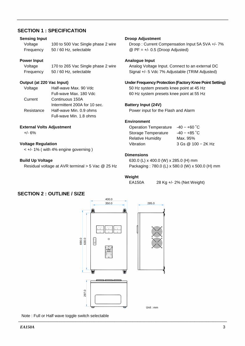
SECTION 1 : SPECIFICATION Sensing Input Droop Adjustment Voltage 100 to 500 Vac Single phase 2 wire Droop : Current Compensation Input 5A 5VA +/- 7% Frequency 50 / 60 Hz, selectable @ PF = +/- 0.5 (Droop Adjusted) Power Input Analogue Input Voltage 170 to 265 Vac Single phase 2 wire Analog Voltage Input. Connect to an external DC Frequency 50 / 60 Hz, selectable Signal +/- 5 Vdc 7% Adjustable (TRIM Adjusted) Output (at 220 Vac Input) Under Frequency Protection (Factory Knee Point Sett ing) Voltage Half-wave Max. 90 Vdc 50 Hz system presets knee point at 45 Hz Full-wave Max. 180 Vdc 60 Hz system presets knee point at 55 Hz Current Continuous 150A Intermittent 200A for 10 sec. Battery Input (24V) Resistance Half-wave Min. 0.9 ohms Power input for the Flash and Alarm Full-wave Min. 1.8 ohms Environment External Volts Adjustment Operation Temperature -40 − +60 ˚C +/- 6% Storage Temperature -40 − +85 ˚C Relative Humidity Max. 95% Voltage Regulation Vibration 3 Gs @ 100 − 2K Hz < +/- 1% ( with 4% engine governing ) Dimensions Build Up Voltage 630.0 (L) x 400.0 (W) x 285.0 (H) mm Residual voltage at AVR terminal > 5 Vac @ 25 Hz Packaging : 780.0 (L) x 580.0 (W) x 500.0 (H) mm Weight EA150A 28 Kg +/- 2% (Net Weight)

SECTION 2 : OUTLINE / SIZE

400.0

630.

0

285.0

A V V

297.

0

350.0

690.

0

Note : Full or Half wave toggle switch selectable

___________________________________________________________________________________________

4 EA150A

SECTION 3 : INTERNAL SPECIFICATION

FANSENSING

0380

440

48

0

220

110

0254

277

220

190

FIELD

A1

A2

S1

S2

C1

C2

SW

1S

W2

SE

NS

ING

CT

INP

UT

FL

. SW

BA

TT

. 24

VA

LA

RM

OU

T

TB2

(J)(K)

POWERAC 220V

FANSENSING

0380

440

48

0

220

110

0254

277

220

190

11

10

321

5

6

7

8

9

12

13 14 15

16

17

Front Panel

4

Half Wave

Full Wave

A A A

Item Content Application

1 EA45C Sensing module

2 Sensing transformer For Sensing power input

3 Fan transformer For Fan power (220V 50/60 Hz)

4 Toggle switch Full Wave / Half Wave selection

5 Diode Rectifier diode

6 Shunt For ammeter

7 SCR Rectifier SCR

8 Field output terminal Connected to the exciter field

9 Power input MCCB Power input 100 − 300 Vac 50/60 Hz

10 EB500 Excitation flash module

11 Terminal TB1 I/O put terminal

12 Terminal TB2 Control terminal

13 Field current meter

14 Field voltage meter

15 Generator voltage meter

16 Over heat lamp

17 EA45AF-1 AVR control unit

Figure 1

___________________________________________________________________________________________

EA150A 5

C1

C2

440

380

220

0-

+ TO

PC

BC

.TS

EN

SIN

GDROOP

TRIM

A1 A2

EA45C

EA45C

SENSING Sensing power input

C.T Current Transformer input N : 5A

TO PCB Connected to the EA45AF-1

DROOP Droop adjustment

TRIM Trim adjustment

A1 A2 Analog input 0 − +/- 5 Vdc

AUTOMATICVOLTAGE REGULATOR

U/F LAMPPOWER LAMP

F S + HI LO

STAB. VOLT. U/F

POWER LAMP Lights up when AVR is powered.

STAB Stability Adjustment Correct stability adjustment must be conducted while the generator is operating without load. First adjust this STAB (POT) clockwise until the voltage becomes unstable, and then slightly adjust it anti-clockwise (about 1/5 turn). When the voltage just reaches the critical point (knee point) of stabilization, where the voltage is stable yet very close to becoming unstable.

U/F LAMP Lights up when the generator is in U/F (Under Frequency Protection)

Select frequency 50 or 60 Hz according to the generator in use(refer to section 4) U/F Under Frequency Protection Adjustment When generator speed falls below the knee point, the under frequency protection circuit will activate and the voltage begin to decrease in linear descend.

VOLT Voltage Adjustment Generator output voltage adjustment.

Figure 2

EA45AF-1

___________________________________________________________________________________________

6 EA150A

SECTION 4 : ATTENTION

4.1 When Installing 4.1.1 Let only experienced professional installer carry

out the installation. 4.1.2 Avoid Installing AVR near high temperature,

moisture, or location where AVR can be easily reached.

4.2 When Generator Is Operating The surface temperature of AVR may reach over 60 ˚C. 4.3 Start Procedure 4.3.1 Setting Check wiring connection and voltage setting (Input

Voltage and Fan Voltage). Set volt trimmer to the minimum position. Set external trimmer to midway position if fitted. Set stability trimmer to maximum position. Connect a voltmeter to field F+, F- terminals. Connect a 300 Vac voltmeter to generator output

voltage terminals. 4.3.2 Start the generator Start up generator with no load. Adjust to the correct

engine speed. Voltage should build up at the lowest voltage level. If the voltage does not build up, please refer to SECTION 7. FIELD FLASHING or contact generator supplier.

Slowly adjust volt trimmer clockwise until rated voltage is reached.

Adjust stability trimmer anticlockwise until the output voltage starts to fluctuate, then carefully adjust stability trimmer clockwise until rated stable voltage is achieved.

SECTION 5 : ADJUSTMENT

5.1 Under Frequency Adjustment Open the enclosure panel. On the back of EA45AF-1 carefully select the frequency setting. Please refer to Figure 2 “EA45AF-1”

EA45AF-1 (Front panel) terminals 1 & 2 Open For 50 Hz. Factory preset at 45 Hz.

EA45AF-1 (Front panel) terminals 1 & 2 Close For 60 Hz. Factory preset at 55 Hz.

5.2 Voltage Adjustment 5.2.1 Please refer to Figure 2 “EA45AF-1” 5.2.2 Carefully turn volt trimmer until rated voltage is

reached. (Clockwise = Increase) 5.2.3 For external voltage adjustment : Connect a 1K

ohms 1W voltage rheostat to the EA45AF-1 (Front panel) terminal 3 & 4.

5.2.4 For long range external voltage adjustment, please refer to Figure 6. Use twisted wire for connection, and if distance exceeds 100 meters, please use isolated twisted only.

The TRIM on the EA45C module must be

adjusted to maximum (Clockwise). 5.3 Stability Adjustment 5.3.1 Please refer to Figure 2 “EA45AF-1” 5.3.2 By adjusting STAB trimmer will provide the

system with stable voltage output. But if it is over adjusted, then the voltage will oscillate (hunt) when heavy load is applied.

5.3.3 It is suggested to use a multi-meter DCV to adjust “stability”. When adjusting, try to make the multi-meter waving to the minimum. This will improve the full load’s voltage drift rate.

SECTION 6 : PARALLELING

If generator is not paralleled, please ignore this section and continue to next section. 6.1 TRIM (EA45C) Please refer to Figure 2 “EA45AF-1”

TRIM works together with a bias voltage applied to terminals A1 and A2. Use the TRIM potentiometer to adjust the DC voltage input that controls the level of the generator’s output voltage. When set anticlockwise the control level is zero, and if moved clockwise the maximum control range is 10%. The signal connected to A1 and A2 can be unipolar (0, +) or bipolar (+,−). 6.2 DROOP (EA45C) Please refer to Figure 2 “EA45AF-1”

DROOP is the adjustment of influence from CT 1, CT 2current compensation input value to the generator output voltage decrease ratio. Voltage droop works when the CT and the AVR senses that the output of the generator voltage and current waveforms are out of synch and the AVR droops the output voltage of the generator to correct it. This adjustment is required when generators are paralleled. For paralleling connection, please refer to Figure 7. The CT capacity must be greater than 5VA with 5 amperes secondary current.

___________________________________________________________________________________________

EA150A 7

Figure 3 Manual Field Flash

SECTION 7 : FIELD FLASHING

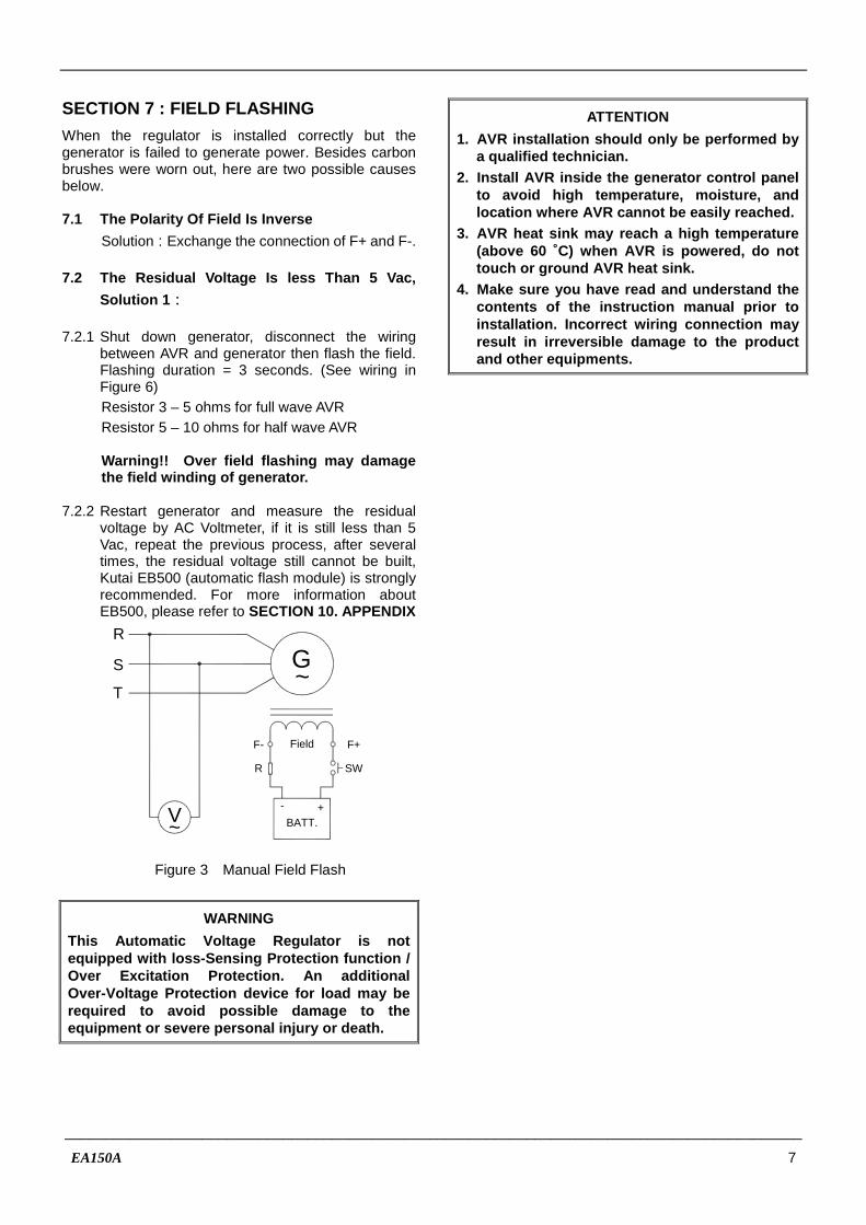
When the regulator is installed correctly but the generator is failed to generate power. Besides carbon brushes were worn out, here are two possible causes below. 7.1 The Polarity Of Field Is Inverse

Solution:Exchange the connection of F+ and F-. 7.2 The Residual Voltage Is less Than 5 Vac,

Solution 1 : 7.2.1 Shut down generator, disconnect the wiring

between AVR and generator then flash the field. Flashing duration = 3 seconds. (See wiring in Figure 6)

Resistor 3 – 5 ohms for full wave AVR Resistor 5 – 10 ohms for half wave AVR Warning !! Over field flashing may damage

the field winding of generator. 7.2.2 Restart generator and measure the residual

voltage by AC Voltmeter, if it is still less than 5 Vac, repeat the previous process, after several times, the residual voltage still cannot be built, Kutai EB500 (automatic flash module) is strongly recommended. For more information about EB500, please refer to SECTION 10. APPENDIX

Field

SWR

- +V

F+F-

BATT.~

G~

T

S

R

WARNING

This Automatic Voltage Regulator is not equipped with loss-Sensing Protection function / Over Excitation Protection. An additional Over-Voltage Protection device for load may be required to avoid possible damage to the equipment or severe personal injury or death.

ATTENTION

1. AVR installation should only be performed by a qualified technician.

2. Install AVR inside the generator control panel to avoid high temperature, moisture, and location where AVR cannot be easily reached.

3. AVR heat sink may reach a high temperature (above 60 ˚C) when AVR is powered, do not touch or ground AVR heat sink.

4. Make sure you have read and understand the contents of the instruction manual prior to installation. Incorrect wiring connection may result in irreversible damage to the product and other equipments.

___________________________________________________________________________________________

8 EA150A

SECTION 8 : SETTING & CONNECTION

SENSING

0380

440

480

220

110

Sensing Input Selector

FAN

0254

277

220

190

Fan Power Input Selector

220V 50/60Hz

FIELD

A1

A2

S1

S2

C1

C2

SW

1S

W2

SE

NS

ING

CT

INP

UT

FL.

SW

BA

TT

. 24V

ALA

RM

OU

T

TB2

(J)(K)

POWERAC 220V

Figure 4

___________________________________________________________________________________________

EA150A 9

EB

500

24V

v~

EA

45C

A2

A1

440V

C1

C2

B+

B -

PCB+

PCB-

VR

EA45AF-1

F+

F-

F+

F-

AC1

AC2

+

-

v-

F-F+

A

0V

G1G2 P1P2

OVER HEAT

480 V

440 V

380 V

220 V

110 V

0 V

277

V

254

V

220

V

190

V

0 V

FAN

Sensing Transformer

Fan Transformer

Power Input

Field

150AT

EA150 Diagram

220V

1K Ω

3

41 2

HZ

ALARM OUT -

ALARM OUT +

TB2

BATT . 24 V -

BATT . 24 V +

SW 2

SW 1

C2

C1

FL

. SW

CT

IN

PU

TS

EN

SIN

G I

NP

UT

S1

A2

A1

S2

J21K

Ω

SW

Shunt

1K Ω

AN

ALO

GIN

PU

T

Field Current Meter

Field Voltage Meter

Generator Voltage Meter

Figure 5

C.T.N:5A

GENERATOR50/60HZ

FIELD

AC

AC

S1

S2

EXT. VOLTS

U

V

W

N

Adjust 1K Ω

JK

PO

WE

R

A1

A2

C1

C2

SW

1S

W2

SE

NS

ING

CT

INP

UT

FL.

SW

BA

TT

. 24V

ALA

RM

OU

TF

IELD

Hig

h oi

l p

ress

ure

SW

To Parallel control device

12

34

Ext

.VR

Hz

Front Panel

Close 60HzOpen 50Hz

Shunt power model

Hea

tsin

kT

emp

sw.

AN

ALO

GIN

PU

T

Figure 6

___________________________________________________________________________________________

10 EA150A

C.T.N:5A

GENERATOR50/60HZ

FIELD

EXT. VOLTS

U

V

W

N

Adjust 1K Ω

A1

A2

C1

C2

SW

1S

W2

CT

INP

UT

FL.

SW

To Parallel control device

12

34

Ext

.VR

Hz

Front Panel

Close 60HzOpen 50Hz

Auxiliary winding power model

AUXILIARYWINDING

AUXILIARYWINDING

PO

WE

RS

EN

SIN

GB

AT

T. 2

4VA

LAR

M O

UT

FIE

LD

Hig

h oi

l p

ress

ure

SW

AC

AC

S1

S2

JK

Hea

tsin

kT

emp

sw.

AN

AL

OG

INP

UT

Figure 7

A1

A2

C1

SW

1S

W2

CT

INP

UT

A1

A2

C1

C2

SW

1S

W2

FL.

SW

Long-range voltage regulation

0~+/-3VDC

Isolated power supply > 0.5 VA

* If distance exceeds 100m , please use use shielded cable .

Twisted Wire

AN

ALO

GIN

PU

T

Figure 8

___________________________________________________________________________________________

EA150A 11

C.T.N:5AGENERATOR

50/60HZ

FIELD

EXT. VOLTS

U

V

W

N

Adjust 1K Ω

A1

A2

C1

C2

SW

1S

W2

CT

INP

UT

FL.

SW

To Parallel control device

12

34

Ext

.VR

Hz

Front Panel

Close 60HzOpen 50Hz

AUXILIARYWINDING

AUXILIARYWINDING

PO

WE

RS

EN

SIN

GB

AT

T. 2

4VA

LAR

M O

UT

FIE

LD

Hig

h oi

l p

ress

ure

SW

AC

AC

S1

S2

JK

ACB 2 N.C

ACB 1

C.T.N:5A

GENERATOR50/60HZ

FIELD

EXT. VOLTS

U

V

W

N

Adjust 1K Ω

A1

A2

C1

C2

SW

1S

W2

CT

INP

UT

FL.

SW

To Parallel control device

12

34

Ext

.VR

Hz

Front Panel

Close 60HzOpen 50Hz

Parallel wiring diagram

AUXILIARYWINDING

AUXILIARYWINDING

PO

WE

RS

EN

SIN

GB

AT

T. 2

4VA

LAR

M O

UT

FIE

LD

Hea

tsin

kT

emp

sw.

Hig

h oi

l p

ress

ure

SW

AC

AC

S1

S2

JK

ACB 2

Hea

tsin

kT

emp

sw.

ACB 1 N.C

AN

ALO

GIN

PU

TA

NA

LOG

INP

UT

Figure 9

___________________________________________________________________________________________

12 EA150A

SECTION 9 : TROUBLE SHOOTING

SYMPTOM POSSIBLE CAUSES SOLUTIONS

Voltage does not build up

Residual voltage below 5 Vac Field flash is required. Please refer to Section 7. FIELD FLASHING

Incorrect wiring Check wiring diagram for proper connection

Engine under speed Increase engine speed to above 25 Hz

Carbon brushes were worn out Replace with new carbon brushes

Low output voltage Voltage set point is not properly adjusted Adjust VOLT POT clockwise to reach desired voltage

External voltage adjusted too low Turn the external VR to reach desired voltage

Under Frequency Protection is activated Please refer to Section 5.1 Under frequency adjustment

Over output voltage Voltage set point is not properly adjusted Adjust VOLT POT anti-clockwise to reach rated voltage

Output voltage unstable (Hunting)

Stability range is not set properly Please refer to 5.3 Stability adjustment

Field voltage or field resistance is too low Connect suitable resistor in series to increase total resistance

※ Appearance and specifications of products are subject to change for improvement without prior notice.

___________________________________________________________________________________________

EA150A 13

SECTION 10 : APPENDIX

EB500 12 / 24 Vdc 1 Shot Auto Flash Module Generator Voltage Build Up Latching Relay

Input Voltage:DC 10 − 30 Vdc

Sensing Voltage:AC 120 / 240 Vac

Flashing Time:1 − 8 sec. (Adjustable)

Trigger Contact:Oil Pressure (Normally Open) Excitation Current:12V 0.8 / 1.2 / 2.4A DC

24V 1.6 / 2.4 / 4.8A DC Dimensions:107.0 (L) x 75.0 (W) x 44.0 (H) mmWeight:210 g +/- 2%

EB500 AUTO FLASH MODULE

AC1

F

AC2

F+

B+

B

B

C

A

10 O

hm5

Ohm

Fla

sh t

imer

adj

.

Diode

Flash Current Selection A, B, C (Open) 12V = 0.8A 24V = 1.6A A − B (Short) 12V = 1.2A 24V = 2.4A B − C (Short) 12V = 2.4A 24V = 4.8A

Fie

ld G~

Battery+ _

Oil pressure or fuel switch. (normally open) A B C

B-

B+

F+

F-

AUTOMATIC VOLTAGEREGULATOR (A.V.R)

10 Ohm

Flash timer adj.

1~8 Sec

A

B

C

NOTE :

EB500

F+F - AC1 AC2

5 Ohm

JUMP A-B FOR 10 OhmJUMP B-C FOR 5 OhmJUMP A-C FOR 0 Ohm

AC2

AC1

ALL OPEN FOR 15 Ohm

59.075.0

91.0

107.

0

15.544.0

5.0


Recommended