100
o2006 Honda Motor Co., Ltd. -All Rights Reserved Owner’s Manual GENERATOR EU6500is See page 78 for instructions on assembling your generator.

31Z2560000X31-Z25-6000
o2006 Honda Motor Co., Ltd.-All Rights ReservedN2eY11000.2006.09
Printed in Japan
Owner’s ManualGENERATOR
EU6500is
Black DIC F10131Z25600 00X31-Z25-6000 EU6500is
See page 78 for instructionson assembling your generator.
Keep this owner’s manual handy, so you can refer to it at any time.This owner’s manual is considered a permanent part of the generatorand should remain with the generator if resold.
The information and specifications included in this publication were ineffect at the time of approval for printing. Honda Motor Co., Ltd.reserves the right, however, to discontinue or change specifications ordesign at any time without notice and without incurring any obligationwhatever.
The engine exhaust from this productcontains chemicals known to the State
of California to cause cancer, birthdefects or other reproductive harm.
06/09/12 12:17:15 31Z25600_001

1
INTRODUCTION
Congratulations on your selection of a Honda generator. We arecertain you will be pleased with your purchase of one of the finestgenerators on the market.
We want to help you get the best results from your new generator andto operate it safely. This manual contains all the information on how todo that; please read it carefully.
As you read this manual, you will find information preceded by asymbol. That information is intended to help you avoid
damage to your generator, other property, or the environment.
When your generator needs scheduled maintenance, keep in mindthat your Honda servicing dealer is specially trained in servicingHonda generators and is supported by the parts and service divisionsof American Honda. Your Honda servicing dealer is dedicated to yoursatisfaction and will be pleased to answer your questions andconcerns.
Best Wishes,Honda Motor Co., Ltd.
We suggest you read the Distributor’s Limited Warranty to fullyunderstand its coverage and your responsibilities of ownership. TheDistributor’s Limited Warranty is a separate document that shouldhave been given to you by your dealer.
06/09/12 12:17:22 31Z25600_002

-
-
-
-
-
-
2
A FEW WORDS ABOUT SAFETY
Safety Labels
Safety Messages
Safety Headings
Safety Section
Instructions
Your safety and the safety of others are very important. And using thisgenerator safely is an important responsibility.
To help you make informed decisions about safety, we have providedoperating procedures and other information on labels and in thismanual. This information alerts you to potential hazards that couldhurt you or others.
Of course, it is not practical or possible to warn you about all thehazards associated with operating or maintaining a generator. Youmust use your own good judgement.
You will find important safety information in a variety of forms,including:
on the generator.
preceded by a safety alert symbol and oneof three signal words, DANGER, WARNING, or CAUTION.
These signal words mean:
be or ifyou don’t follow instructions.
be or ifyou don’t follow instructions.
be if you don’t followinstructions.
such as IMPORTANT SAFETY INFORMATION.
such as
how to use this generator correctly and safely.
This entire book is filled with important safety information pleaseread it carefully.
You WILL KILLED SERIOUSLY HURT
You CAN KILLED SERIOUSLY HURT
You CAN HURT
GENERATOR SAFETY .
06/09/12 12:17:33 31Z25600_003
3
CONTENTS
................................................................................GENERATOR SAFETY .6
........................................................................CONTROLS & FEATURES .10
...............................................................................BEFORE OPERATION .24
..................................................IMPORTANT SAFETY INFORMATION .6......................................................................Operator Responsibility .6
.................................................................Carbon Monoxide Hazards .6.......................................................................Electric Shock Hazards .7........................................................................Fire and Burn Hazards .7
.................................................................................Refuel With Care .8.................................................................SAFETY LABEL LOCATIONS .9
...........................................COMPONENT & CONTROL LOCATIONS .10............................................................................................CONTROLS .12
................................................................................Fuel Valve Lever .12....................................................................................Engine Switch .12.....................................................................................Recoil Starter .13
.........................................................................EcoThrottle Switch .13...................................................................Voltage Selector Switch .14
.........................................................................AC Circuit Protectors .14..................................................................................Folding Handle .15
...........................................................................Maintenance Cover .16.............................................................................................FEATURES .17
...............................................................................Ground Terminal .17................................................................................Output Indicator .18
............................................................................Overload Indicator .18
............................................................................Oil Alert Indicator .19.........................................................................................i-Monitor .20.........................................................................................Fuel Gauge .23
................................................ARE YOU READY TO GET STARTED? .24.........................................................................................Knowledge .24
..............................................IS YOUR GENERATOR READY TO GO? .24...............................................................................Check the Engine .25
..............................................................Battery Maintenance Cover .25
TM
TM
06/09/12 12:17:37 31Z25600_004

4
CONTENTS
..............................................................................................OPERATION .26
.............................................................SERVICING YOUR GENERATOR .41
..................................................................................................STORAGE .60
.....................................................SAFE OPERATING PRECAUTIONS .26......................................................................STARTING THE ENGINE .27
...................Starting the engine with remote control (optional part) .30......................................................................STOPPING THE ENGINE .31
.................Stopping the engine with remote control (optional part) .32.....................................................................................AC OPERATION .33
.................................................................................AC Applications .35...................................................................AC Receptacle Selection .36...................................................................ECOTHROTTLE SYSTEM .38
...............................................................................STAND BY POWER .39...............................Connections to a Building’s Electrical System .39
.................................................................................System Ground .39.......................................................................Special Requirements .40
.............................................THE IMPORTANCE OF MAINTENANCE .41......................................................................MAINTENANCE SAFETY .42
............................................................................Safety Precautions .42................................................................MAINTENANCE SCHEDULE .43
...........................................................................................REFUELING .44...............................................................FUEL RECOMMENDATIONS .45
..................................................................ENGINE OIL LEVEL CHECK .46...........................................................................ENGINE OIL CHANGE .47
....................................................ENGINE OIL RECOMMENDATIONS .48........................................................................AIR CLEANER SERVICE .49
.............................................................FOAM AIR FILTER CLEANING .50.................................................................SEDIMENT CUP CLEANING .51
.........................................................................SPARK PLUG SERVICE .52................................................................SPARK ARRESTER SERVICE .54
...............................................................................BATTERY SERVICE .55......................................................................................................FUSE .59
....................................................................STORAGE PREPARATION .60.............................................................................................Cleaning .60
.....................................................................................................Fuel .60..........................................................................................Engine Oil .63
...................................................................STORAGE PRECAUTIONS .64................................................................REMOVAL FROM STORAGE .64
TM
06/09/12 12:17:42 31Z25600_005

5
CONTENTS
......................................................................................TRANSPORTING .65
.......................................TAKING CARE OF UNEXPECTED PROBLEMS .66
..........................................TECHNICAL & CONSUMER INFORMATION .69
...............................................................................................ASSEMBLY .78
....................................................................................OPTIONAL PARTS .87
........................................................................................................INDEX .90
.............................QUICK REFERENCE INFORMATION .Inside back cover
...................................................................ENGINE WILL NOT START .66.......................................................................ENGINE LACKS POWER .67
....................................................NO POWER AT THE RECEPTACLES .68
................................................................TECHNICAL INFORMATION .69...................................................................Serial Number Location .69
....................Carburetor Modification for High Altitude Operation .70............................................Emission Control System Information .71
.............................................................................................Air Index .73....................................................................................Specifications .74
.................................................................................Wiring Diagram .75...............................................................CONSUMER INFORMATION .76
...........................................................................Honda Publications .76.........................................................Customer Service Information .77
..................................................................................................SAFETY .78..............................................The Importance of Proper Assembly .78
..........................................................Important Safety Precautions .79............................................................................................ASSEMBLY .80..........................................................................................Unpacking .80........................................................................................Loose Parts .80
........................................................................Wheel Kit Installation .81............................................................................Handle Installation .82..........................................................................Rear Bar Installation .83
...........................................................................................Engine oil .85.....................................................................................................Fuel .85
..................................................................................Battery Voltage .86...........................................................................BEFORE OPERATION .86
............................................................................Remote Control Kit .87..........................................................................................Hanger Kit .89
06/09/12 12:17:46 31Z25600_006

6
GENERATOR SAFETY
Operator Responsibility
Carbon Monoxide Hazards
IMPORTANT SAFETY INFORMATION
Honda generators are designed for use with electrical equipment thathas suitable power requirements. Other uses can result in injury to theoperator or damage to the generator and other property.Most accidents can be prevented if you follow all instructions in thismanual and on the generator. The most common hazards arediscussed below, along with the best way to protect yourself andothers.
Be sure that anyone who operates the generator receives properinstruction. Do not let children operate the generator withoutparental supervision.
Exhaust contains poisonous carbon monoxide, a colorless, odorlessgas. Breathing exhaust can cause loss of consciousness and maylead to death.
Know how to stop the generator quickly in case of emergency.
Understand the use of all generator controls, output receptacles,and connections.
Operate outdoors away from buildings, open doors or windows.
Never run the generator in a closed or partially enclosed area.
06/09/12 12:17:55 31Z25600_007

-
--
7
GENERATOR SAFETY
Electric Shock Hazards
Fire and Burn Hazards
The generator produces enough electric power to cause a seriousshock or electrocution if misused.
Using a generator or electrical appliance in wet conditions, such asrain or snow, or near a pool or sprinkler system, or when your handsare wet, could result in electrocution. Keep the generator dry.
If the generator is stored outdoors, unprotected from the weather,check all of the electrical components on the control panel, beforeeach use. Moisture or ice can cause a malfunction or short circuit inelectrical components which could result in electrocution.
Do not connect to a building electrical system unless an isolationswitch has been installed by a qualified electrician.
The muffler becomes very hot during operation and remains hot fora while after stopping the engine. Be careful not to touch the mufflerwhile it is hot. Let the engine cool before storing the generatorindoors.
Keep the generator at least 3 feet (1 meter) away from buildingsand other equipment during operation.Do not enclose the generator in any structure.Keep flammable materials away from the generator.
The exhaust system gets hot enough to ignite some materials.
06/09/12 12:18:05 31Z25600_008

8
GENERATOR SAFETY
Refuel With Care
Gasoline is extremely flammable, and gasoline vapor can explode.Allow the engine to cool if the generator has been in operation. Refuelonly outdoors in a well-ventilated area with the engine OFF. Do notoverfill the fuel tank. Never smoke near gasoline, and keep otherflames and sparks away. Always store gasoline in an approvedcontainer. Make sure that any spilled fuel has been wiped up beforestarting the engine.
06/09/12 12:18:09 31Z25600_009
9
GENERATOR SAFETY
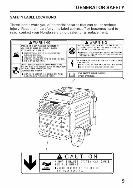
SAFETY LABEL LOCATIONS
These labels warn you of potential hazards that can cause seriousinjury. Read them carefully. If a label comes off or becomes hard toread, contact your Honda servicing dealer for a replacement.
06/09/12 12:18:26 31Z25600_010

10
CONTROLS & FEATURES
COMPONENT & CONTROL LOCATIONS
OUTPUTINDICATOR
CIRCUIT PROTECTORS
FUEL VALVE LEVER
VOLTAGE SELECTOR SWITCH
ECOTHROTTLE SWITCH
ENGINE SWITCH
i-MONITOR
i-MONITORBUTTON
OIL ALERTINDICATOR
OVERLOADINDICATOR
RECEPTACLES
Use the two illustrations on these pages to locate and identify themost frequently used controls.
06/09/12 12:18:33 31Z25600_011

11
CONTROL & FEATURES
AIR CLEANER
FUEL TANK CAP
STARTER GRIP
GROUND TERMINAL
STANDOIL DRAIN PLUG
OIL FILLERCAP/DIPSTICK
FUEL GAUGE
HANDLE
WHEELMUFFLER TIP
SPARK PLUGINSPECTION COVER
LEFT MAINTENANCE COVER
RIGHT MAINTENANCECOVER
FUSE(inside battery maintenance cover)
BATTERY(inside batterymaintenance cover)
06/09/12 12:18:39 31Z25600_012

-
-
-
-
12
CONTROL & FEATURES
CONTROLS
Fuel Valve Lever
Engine Switch
FUEL VALVE LEVER
OOFFFF
OONN
OOFFFF
OONN
OOFFFF
SSTTAARRTT
ENGINE SWITCH
ENGINE SWITCH
RREEMMOOTTEE
The fuel valve must be in the ONposition for the engine to run.
After stopping the engine, turnthe fuel valve to the OFF position.
The fuel valve lever is located onthe control panel.
The engine switch controls theignition system, and it operatesthe electric starter.
OFF Stops the engine. Theengine switch key can beremoved/inserted.
REMOTE For using the remotecontrol kit (optional parts).
START Operates the electricstarter.
ON Running position, and forstarting with the recoil starter.
06/09/12 12:18:53 31Z25600_013

-
-
13
CONTROL & FEATURES
Recoil Starter
EcoThrottle Switch
STARTER GRIP
OFF
20°
ON
ECOTHROTTLE SWITCH
OFF The EcoThrottle systemdoes not operate. Generatoroperates at full speed.
ON Recommended to minimizefuel consumption and furtherreduce noise levels when areduced load or no load is appliedto the generator.
If high electrical loads are connected simultaneously, turn theEcoThrottle switch to the OFF position to reduce voltage changes.
The EcoThrottle system automatically reduces engine speed when allloads are turned off or disconnected. When appliances are turned onor reconnected, the engine returns to the proper speed to power theelectrical load.
Do not let the starter rope rubagainst the generator body orthe rope will wear outprematurely.
Do not allow the starter grip tosnap back against the engine.Return it gently to preventdamage to the starter.
Do not exceed 20 degrees fromhorizontal when pulling thestarter grip.
Pulling the starter grip operatesthe recoil starter to crank theengine for starting.
Used when the battery voltage istoo low to turn the starter motor.
TM
06/09/12 12:19:06 31Z25600_014

14
CONTROL & FEATURES
Voltage Selector Switch
Switch Position
AC Circuit Protectors
120/240V:
120V ONLY:
AC CIRCUIT PROTECTOR
PUSH
ON
VOLTAGE SELECTOR SWITCH
CIRCUIT PROTECTORfor Receptacle
CIRCUIT PROTECTORfor Receptacle
CIRCUIT PROTECTORfor Receptacle
120V 30A
120/240V 30A
OFF
120V 20A
120V/240V
120V ONLY
CIRCUIT PROTECTORfor Receptacle
120V 20A
The AC circuit protectors will automatically switch OFF if there is ashort circuit or a significant overload of the generator at eachreceptacle. If an AC circuit protector switches OFF automatically, checkthat the appliance is working properly and does not exceed the ratedload capacity of the circuit before resetting the AC circuit protector ON.
Select the voltage before starting the engine.
The 120V and 120/240V receptacles can be usedsimultaneously.
ONLY the 120V receptacles can be used. Do not use the120/240V receptacle in this position. The most power will be availableat the 30A 120V locking plug receptacle.
The voltage selector switch changes generator output to produce‘‘120V ONLY’’ or ‘‘120/240V’’. If a 240V appliance is connected to the 4-prong receptacle, the switch must be in the ‘‘120/240V’’ position. Ifonly the 120V 3-prong receptacles are being used, select the ‘‘120VONLY’’ position.
06/09/12 12:19:18 31Z25600_015

15
CONTROL & FEATURES
Folding Handle
To Extend The Handle
To Fold The Handle
HANDLE HANDLE LOCK LEVER
Handletransportposition
Generatorstationaryposition
The foldable handle is intended for ease of transportation and shouldbe folded when the generator is stationary. Do not rest objects on theextended the handle.
Lift handle upward. Lock levers will lock and secure the handle intoplace.
Lower the handle.Press both handle lock levers downward.
2.1.
06/09/12 12:19:28 31Z25600_016

16
CONTROL & FEATURES
Maintenance Cover
Work made with the right maintenance cover open:
Work made with the left maintenance cover open:
To open:
To close:
RIGHT MAINTENANCECOVER
LEFT MAINTENANCECOVER
Close the cover and push.
RATCH RATCH
RATCH
Open the maintenance cover, too, to use the recoil starter when thebattery is discharged. Be sure to close the maintenance cover whilethe generator is running.
Turn the ratch 90° to unlock and open the maintenance cover.
Turn the ratch 90° to lock while pushing the cover.
Engine oil inspection/replacement
Spark plug inspection/replacementAir cleaner inspection/cleaningSediment cup cleaning
Open and close the maintenance cover for maintenance of theEU6500is.
06/09/12 12:19:42 31Z25600_017

17
CONTROL & FEATURES
FEATURES
Ground Terminal
GROUND TERMINAL
The ground terminal is connected to the frame of the generator, themetal non-current-carrying parts of the generator, and the groundterminals of each receptacle.
Before using the ground terminal, consult a qualified electrician,electrical inspector or local agency having jurisdiction for local codesor ordinances that apply to the intended use of the generator.
06/09/12 12:19:48 31Z25600_018

18
CONTROL & FEATURES
Output Indicator
Overload Indicator
OUTPUTINDICATOR(GREEN)
OVERLOADINDICATOR (RED)
The output indicator (green) is illuminated when the generator isoperating normally. It indicates that the generator is producingelectrical power at the receptacles.
If the generator is overloaded, or if there is a short circuit in aconnected appliance, or if the inverter is overheated, the overloadindicator (red) will go ON. When the generator is operating overloaded,the overload indicator (red) will stay ON, and after about five seconds,current to the connected appliance(s) will shut off, and the outputindicator (green) will go OFF.
06/09/12 12:19:55 31Z25600_019

19
CONTROL & FEATURES
Oil Alert Indicator
It blinks.
OIL ALERT(RED)
The Oil Alert system is designed to prevent engine damage caused byan insufficient amount of oil in the crankcase. Before the oil level in thecrankcase can fall below a safe limit, the Oil Alert indicator comes onand the Oil Alert system automatically stops engine (the engine switchwill remains the ON position).
If the engine stops or the Oil Alert indicator comes on when you turnthe engine switch to START or pull the starter grip, check the engineoil level (see page ) before troubleshooting in other areas.Even when oil is added to the engine, the generator will not restartuntil the Oil Alert indicator is reset. To reset the Oil Alert indicator, turnthe engine switch OFF, add the proper amount of oil (see page ),and then turn the engine switch back ON.
The i-Monitor display will shows ‘‘OIL’’ on the screen and the OilAlert indicator illuminats.
47
46
06/09/12 12:20:02 31Z25600_020

-
20
CONTROL & FEATURES
i-Monitor
i-Monitor at Startup
Display Backlight Flashes
i-Monitor Display
i-Monitor Display Mode 1 Total Operating Hours
SINGLE-DIGITSCREEN DISPLAY
FOUR-DIGITSCREEN DISPLAY
i-MONITOR BUTTON
TM
The i-Monitor is a user interface that allows the operator to view (whenthe generator is running) total operating time in hours, generatoroutput, engine RPM, battery voltage and error messages. The differentdisplay modes are selected by pressing the i-Monitor button.
If the key is left in the ON position for over 30 seconds without startingthe engine, the display will start to flash.
The i-Monitor display is divided into two screens. The single-digitscreen displays the i-Monitor mode which is represented by a number1 through 4. The four-digit screen displays the four mode values orany activated error messages.
This mode displays the total operating hours of the generator. Whenthe generator is running, the total operating time accumulates. If thetotal operating time is less than one hour, the numeric display will be‘‘0.’’ When the operating time is one hour or greater, the display willbe ‘‘1’’ or ‘‘2’’ and so on. Base the generator’s maintenance scheduleon the accumulated time displayed.
During start up, the i-Monitor display and all three indicators willsimultaneously blink once. The condition of the i-Monitor displayand all three indicators can be checked. Once the generator isrunning, the Output indicator (green) and the i-Monitor display willremain lit.
06/09/12 12:20:15 31Z25600_021

-
-
-
21
CONTROL & FEATURES
i-Monitor Display Mode 2 Power Output
i-Monitor Display Mode 3 Engine RPM
i-Monitor Display Mode 4 Battery Voltage
This mode displays an approximate generator output on the displayscreen. The output is expressed in VA (volt-amperes). The outputvalue is not an exact measurement and should be regarded as areference only. Power output will not display until a load is connectedto the generator.
When the i-Monitor is in this mode, the engine’s speed, expressed inrevolutions-per-minute (RPM) is displayed.
This mode displays the battery condition, expressed in Volts DC.
06/09/12 12:20:27 31Z25600_022

22
CONTROL & FEATURES
i-Monitor Low Battery Message
i-Monitor System Error Messages
OVERLOAD INDICATOR LIGHT
ERROR MESSAGE(Example: E-01)
If the generator has a system malfunction, it will show an errormessage on the i-Monitor display. During remote control operation, anE-01 error message may display if the starter button is pressed formore than 10 seconds. With an E-01 error message, the engine willstay running and the electrical output may stay constant.Normal remote control operation will be restored after the E-01 errormessage clears. If the E-01 error message will not clear or if any othererror message displays, contact an authorized Honda generator dealer.
If the engine switch is turned to the START position and ‘‘batt’’ isshown on the i-Monitor display, the battery voltage is too low tooperate the engine’s electric starter. Use the recoil starter to start thegenerator. Have the battery recharged and checked (see page ).58
06/09/12 12:20:36 31Z25600_023

23
CONTROL & FEATURES
Fuel Gauge
FUEL TANK CAP
FULL
EMPTY
FUEL GAUGE
The fuel gauge is a mechanical device that measures the fuel level inthe tank. The red indicator in the window will reference the level inrelation to full or empty. To provide increased operating time, startwith a full tank before beginning operation. Check the fuel level withthe generator on a level surface. Always refuel with the engine OFFand cool.
06/09/12 12:20:41 31Z25600_024

24
BEFORE OPERATION
ARE YOU READY TO GET STARTED?
Knowledge
IS YOUR GENERATOR READY TO GO?
Your safety is your responsibility. A little time spent in preparation willsignificantly reduce your risk of injury.
Read and understand this manual. Know what the controls do andhow to operate them.
Familiarize yourself with the generator and its operation before youbegin using it. Know how to quickly shut off the generator in case ofan emergency.
For your safety, and to maximize the service life of your equipment, itis very important to take a few moments before you operate thegenerator to check its condition. Be sure to take care of any problemyou find, or have your servicing dealer correct it, before you operatethe generator.
Improperly maintaining thisgenerator, or failing to correct aproblem before operation, couldcause a malfunction in which youcould be seriously injured.
Always perform a preoperationinspection before each operation,and correct any problem.
Before beginning your preoperation checks, be sure the generator ison a level surface and the engine switch is in the OFF position.
To prevent a possible fire, keep the generator at least 3 feet (1 meter)away from building walls and other equipment during operation. Donot place flammable objects close to the engine.
If the generator is being used to power appliances, be sure that theydo not exceed the generator’s load rating (see page ).35
06/09/12 12:20:53 31Z25600_025

25
BEFORE OPERATION
Check the Engine
Battery Maintenance Cover
BATTERY MAINTENANCE COVER
Check the oil level (see page ). A low oil level will cause the Oil Alertsystem to shut down the engine.
Check the air filter (see page ). A dirty air filter will restrict air flow tothe carburetor, reducing engine and generator performance.
Check the fuel level (see page ). Starting with a full tank will help toeliminate or reduce operating interruptions for refueling.
Never operate the generator without the battery maintenance cover inplace, as poor engine and generator performance will result.
46
49
44
06/09/12 12:21:02 31Z25600_026

26
SAFE OPERATING PRECAUTIONS
OPERATION
Before operating the generator for the first time, please review theGENERATOR SAFETY section and the chapter titled BEFOREOPERATION.
For your safety, avoid starting or operating the generator in anenclosed area such as a garage. Your generator’s exhaust containspoisonous carbon monoxide gas that can collect rapidly in anenclosed area and cause illness or death.
Carbon monoxide gas is toxic.Breathing it can causeunconsciousness and even kill you.
Avoid any enclosed areas oractivities that expose you to carbonmonoxide.
Before connecting an AC appliance or power cord to the generator:
Use grounded 3-prong extension cords, tools, and appliances, ordouble-insulated tools and appliances.Inspect cords and plugs, and replace if damaged.Make sure that the appliance is in good working order. Faultyappliances or power cords can create a potential for electric shock.Make sure the electrical rating of the tool or appliance does notexceed that of the generator. Never exceed the maximum powerrating of the generator. Power levels between rated and maximummay be used for no more than 30 minutes.Operate the generator at least 3 feet (1 meter) away from buildingsand other equipment.Do not operate the generator in an enclosed structure.
06/09/12 12:21:15 31Z25600_027

27
OPERATION
STARTING THE ENGINE
FUEL VALVE LEVER
OONN
OOFFFF
VOLTAGE SELECTOR SWITCH
120VONLY
120V/240V
ONOOFFFF
ECOTHROTTLE SWITCH
Refer to Safe Operating Precautions on page .
Make sure that all appliancesare disconnected from the ACreceptacles. The generator maybe hard to start if a load isconnected.
Set the Voltage Selector Switchto match the voltagerequirements for theapplication.
Turn the fuel valve lever to theON position.
Make sure the EcoThrottleswitch is in the OFF position, ormore time will be required forwarm up.
1.
2.
3.
25
4.
06/09/12 12:21:26 31Z25600_028

28
OPERATION
OONN
OOFFFF SSTTAARRTT
ENGINE SWITCH
Turn the engine switch to theSTART position, and hold itthere until the engine starts.When the engine starts, releasethe key, allowing the switch toreturn to the ON position.
If the engine fails to start within5 seconds, release the key, andwait at least 10 seconds beforeoperating the starter again.
Using the electric starter for more than 5 seconds at a time willoverheat the starter motor and can damage it.
5.
06/09/12 12:21:33 31Z25600_029
29
OPERATION
OONN
ENGINE SWITCH
ON
OOFFFF
OOFFFF
STARTER GRIP
20°
ECOTHROTTLE SWITCH
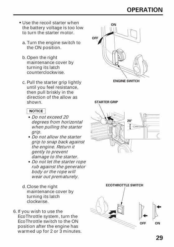
Use the recoil starter whenthe battery voltage is too lowto turn the starter motor.
If you wish to use theEcoThrottle system, turn theEcoThrottle switch to the ONposition after the engine haswarmed up for 2 or 3 minutes.
Close the rightmaintenance cover byturning its latchclockwise.
Do not let the starter roperub against the generatorbody or the rope willwear out prematurely.
Do not allow the startergrip to snap back againstthe engine. Return itgently to preventdamage to the starter.
Do not exceed 20degrees from horizontalwhen pulling the startergrip.
Pull the starter grip lightlyuntil you feel resistance,then pull briskly in thedirection of the allow asshown.
Open the rightmaintenance cover byturning its latchcounterclockwise.
Turn the engine switch tothe ON position.
a.
6.
b.
c.
d.
06/09/12 12:21:47 31Z25600_030

30
OPERATION
Starting the engine with remote control (optional part)
OOFFFF
OFFENGINE SWITCH
REMOTE
PILOT LAMP
START BUTTON
FUEL VALVE LEVER
OONN
Determine the voltage requirements and adjust the voltage selectorswitch, as needed.
Turn the fuel valve to the ON position.
Turn the engine switch to the REMOTE (far left) position.
Press and hold the start button until the engine pilot lampilluminates. The start button will automatically be disabled after theengine starts.
Using the electric starter for more than 5 seconds at a time willoverheat the starter motor and can damage it.
If the engine fails to start within 5 seconds, release the button, andwait at least 10 seconds before operating the starter again.
1.
2.
3.
4.
06/09/12 12:21:57 31Z25600_031
31
OPERATION
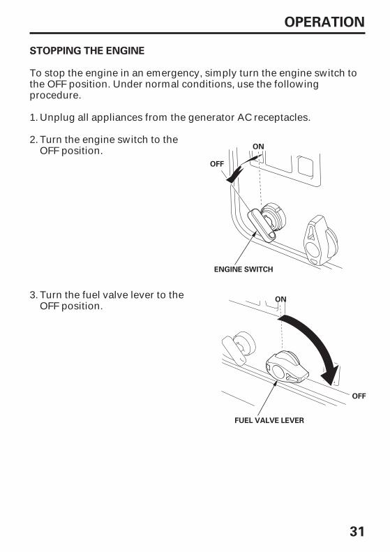
STOPPING THE ENGINE
OONN
ENGINE SWITCH
OONN
FUEL VALVE LEVER
OOFFFF
OOFFFF
To stop the engine in an emergency, simply turn the engine switch tothe OFF position. Under normal conditions, use the followingprocedure.
Turn the fuel valve lever to theOFF position.
Turn the engine switch to theOFF position.
Unplug all appliances from the generator AC receptacles.1.
2.
3.
06/09/12 12:22:06 31Z25600_032

32
OPERATION
Stopping the engine with remote control (optional part)
OOFFFF
ENGINE SWITCH
REMOTE
STOP BUTTONPILOT LAMP
OOFFFF
FUEL VALVE LEVER
OONN
Turn the engine switch to the OFF position.Turn the fuel valve lever to the OFF position.
Press the stop button.1.
2.3.
06/09/12 12:22:14 31Z25600_033

33
OPERATION
AC OPERATION
120V/240V
120V ONLY
VOLTAGE SELECTOR SWITCH
OUTPUTINDICATOR(GREEN)
OVERLOADINDICATOR(RED)
If an appliance begins to operate abnormally, becomes sluggish orstops suddenly, turn it off immediately. Disconnect the appliance, anddetermine whether the problem is in the appliance, or if the rated loadcapacity of the generator has been exceeded.
Turn the voltage selector switch to either position.With the voltage selector switch in the ‘‘120/240V’’ position, you canuse the 120V and 120/240V receptacles simultaneously. If you areNOT using the 120/240V receptacle, but require more power fromthe 120V locking plug receptacle, then select the ‘‘120V ONLY’’position.
Substantial overloading that continuously lights the overload indicator(red) may damage the generator. Marginal overloading thattemporarily lights the overload indicator (red) may shorten the servicelife of the generator.
Start the engine and makesure the output indicator(green) comes on.
1.
2.
06/09/12 12:22:23 31Z25600_034

34
OPERATION
PLUGMost motorized appliancesrequire more than their ratedwattage for startup.
Plug in the appliance.
Determine if the cause is a short circuit in a connected appliance, anoverload, or an overheated inverter. Correct the problem and restartthe generator.
Before connecting an appliance to the generator, make sure that it is ingood order and that its electrical rating does not exceed that of thegenerator. Then start the generator and connect the appliance powercord.
If the generator is overloaded, or if there is a short circuit in aconnected appliance, or if the inverter is overheated, the overloadindicator (red) will come ON. The overload indicator (red) will stay ON,and after about five seconds, current to the connected appliance(s) willshut off, and the output indicator (green) will go OFF. Stop the engineand investigate the problem.
When an electric motor is started, the overload indicator (red) maycome on. This is normal if the overload indicator (red) goes off afterabout five seconds. If the overload indicator (red) stays on, consult anauthorized Honda generator dealer.
3.
06/09/12 12:22:32 31Z25600_035

35
OPERATION
AC ApplicationsBefore connecting an appliance or power cord to the generator:
Make sure that it is in good working order. Faulty appliances orpower cords can create a potential for electrical shock.
If an appliance begins to operate abnormally, becomes sluggish orstops suddenly, turn it off immediately. Disconnect the appliance,and determine whether the problem is the appliance, or if the ratedload capacity of the generator has been exceeded.
Make sure that the electrical rating of the tool or appliance does notexceed that of the generator. Never exceed the maximum powerrating of the generator. Power levels between rated and maximummay be used for no more than 30 minutes.
Limit operation requiring maximum power to 30 minutes.Maximum power is:
Substantial overloading will open the circuit breaker. Exceeding thetime limit for maximum power operation or slightly overloading thegenerator may not switch the circuit breaker or circuit protector OFF,but will shorten the service life of the generator.
6,500 VA
The total power requirements (VA) of all appliances connected mustbe considered. Appliance and power tool manufacturers usually listrating information near the model number or serial number.
5,500 VA
For continuous operation (longer than 30 minutes), do not exceed therated power.Rated power is:
06/09/12 12:22:43 31Z25600_036

+ +
+
36
OPERATION
AC Receptacle Selection
The generator has separate main power producing circuits. These twocircuits supply power to different receptacles shown when the voltageselector switch is in the 120/240 V position.
When two or more receptacles are used, prevent overloading bydividing the load between the two power circuits.
The chart below shows the rated load in amperes that can beconnected to each receptacle to balance the generator when the 120/240 V locking plug receptacle is used for 120 V.The total rated ampere draw is: 45.8 A
Main power circuit
Main Circuit I
Main Circuit II
Receptacles poweredby each main circuit
1, 3 and 4
2 and 5
Power distribution
1 3 4=22.9A rated.
2 5=22.9A rated.
06/09/12 12:22:50 31Z25600_037

37
OPERATION
120V 20A
120/240V 30A
120V 30A 120V 20A
Receptacle 1 has a 15A load connected to it. Receptacle 3 has a 10Aload connected to it. Both receptacles are powered by main powercircuit I. The equation tells us that the total power draw on circuit I is25A. This is a substantial overload of this circuit. To eliminate theexcess power draw on circuit I, the load from receptacle 3 should beswitched to receptacle 2. Now circuit I is powering the 15A load (lessthan 18.8A) and circuit II is powering the 10A load (less than 18.8A).
06/09/12 12:22:55 31Z25600_038

38
OPERATION
ECOTHROTTLE SYSTEM
ONOOFFFF
ECOTHROTTLE SWITCH
TM
Appliances with large start-up power demands may not allow theengine to reach normal operating rpm when they are connected to thegenerator. Turn the EcoThrottle to the OFF position and connect theappliance to the generator. If the engine still will not reach normaloperating speed, check that the appliance does not exceed the ratedload capacity of the generator.
If high electrical loads are connected simultaneously, turn theEcoThrottle switch to the OFF position to reduce voltage changes.
The EcoThrottle system is not effective for use with appliances thatrequire only momentary power. If the tool or appliance will be turnedON and OFF quickly, the EcoThrottle switch should be in the OFFposition.
With the switch in the ON position, engine speed is automaticallylowered when loads are reduced, turned OFF or disconnected. Whenappliances are turned ON or reconnected, the engine returns to theproper speed to power the electrical load. In the OFF position, theEcoThrottle system does not operate.
06/09/12 12:23:02 31Z25600_039

39
OPERATION
STAND BY POWER
System Ground
Connections to a Building’s Electrical System
Honda portable generators have a system ground that connects thegenerator frame components to the ground terminals in the AC outputreceptacles. The system ground is not connected to the AC neutralwire. If the generator is tested with a receptacle tester, it will not showthe same ground circuit condition as for a home receptacle.
In some areas, generators are required by law to be registered withlocal utility companies. Check local regulations for proper registrationand use procedures.
Improper connections to a building’selectrical system can allow currentfrom the generator to backfeed intothe utility lines.
Such backfeed may electrocuteutility company workers or otherswho contact the lines during apower outage, and the generatormay explode, burn, or cause fireswhen utility power is restored.
Consult the utility company or aqualified electrician prior to makingany power connections.
Your generator can supply power to a building’s electrical system. Ifthe generator will be used as an alternative to utility company power,an isolation switch must be installed to disconnect the utility linesfrom the building when the generator is connected. Installation mustbe performed by a qualified electrician and must comply with allapplicable laws and electrical codes.
06/09/12 12:23:10 31Z25600_040

40
OPERATION
Special Requirements
There may be Federal or State Occupational Safety and HealthAdministration (OSHA) regulations, local codes, or ordinances thatapply to the intended use of the generator. Please consult a qualifiedelectrician, electrical inspector, or the local agency having jurisdiction.
In some areas, generators are required to be registered with localutility companies.
If the generator is used at a construction site, there may beadditional regulations that must be observed.
06/09/12 12:23:16 31Z25600_041

41
SERVICING YOUR GENERATOR
THE IMPORTANCE OF MAINTENANCE
Maintenance, replacement, or repair of the emission control devicesand systems may be performed by any engine repair establishment orindividual, using parts that are ‘‘certified’’ to EPA standards.
Good maintenance is essential for safe, economical, and trouble freeoperation. It will also help reduce air pollution.
To help you properly care for your generator, the following pagesinclude a maintenance schedule, routine inspection procedures, andsimple maintenance procedures using basic hand tools. Other servicetasks that are more difficult, or require special tools, are best handledby professionals and are normally performed by a Honda technician orother qualified mechanic.
The maintenance schedule applies to normal operating conditions. Ifyou operate your generator under unusual conditions, such assustained high-load or high-temperature operation, or use it in dustyconditions, consult your servicing dealer for recommendationsapplicable to your individual needs and use.
Improper maintenance, or failure tocorrect a problem before operation,can cause a malfunction in whichyou can be seriously hurt or killed.
Always follow the inspection andmaintenance recommendations andschedules in this owner’s manual.
Remember that your servicing dealer knows your generator best andis fully equipped to maintain and repair it.
To ensure the best quality and reliability, use only new, genuineHonda parts or their equivalents for repair and replacement.
06/09/12 12:23:24 31Z25600_042

-
-
-
42
SERVICING YOUR GENERATOR
MAINTENANCE SAFETY
Safety Precautions
Carbon monoxide poisoning from engine exhaust.
Burns from hot parts.
Injury from moving parts.
Some of the most important safety precautions follow. However, wecannot warn you of every conceivable hazard that can arise inperforming maintenance. Only you can decide whether or not youshould perform a given task.
Failure to properly followmaintenance instructions andprecautions can cause you to beseriously hurt or killed.
Always follow the procedures andprecautions in the owner’s manual.
Make sure the engine is off before you begin any maintenance orrepairs. This will eliminate several potential hazards:
Be sure there is adequate ventilation whenever you operate theengine.
Let the engine and exhaust system cool before touching.
Do not run the engine unless instructed to do so.
Read the instructions before you begin, and make sure you have thetools and skills required.
To reduce the possibility of fire or explosion, be careful whenworking around gasoline. Use only a nonflammable solvent, notgasoline, to clean parts. Keep cigarettes, sparks, and flames awayfrom all fuel-related parts.
06/09/12 12:23:35 31Z25600_043

43
SERVICING YOUR GENERATOR
MAINTENANCE SCHEDULE
REGULAR SERVICE PERIOD (3)ITEM Each
usePerform at every indicated month oroperating hour interval, whichever comesfirst.
(1)
Check levelChangeCheckCleanCleanCheck-adjustReplaceCleanCheck-adjustClean
CleanCheck
(2)
(2)
Engine oil
Air filter
Sediment cupSpark plug
Spark arresterValve clearanceCombustionchamberFuel tank and filterFuel tube
After every 500 Hrs. (2)
Every 2 years (Replace if necessary) (2)
Service more frequently when used in dusty areas.These items should be serviced by your servicing dealer, unless you have the proper toolsand are mechanically proficient. Refer to Honda shop manual for service procedures.For commercial use, log hours of operation to determine proper maintenance intervals.
Failure to follow this maintenance schedule could result in non-warrantable failures.
4647495051525254
(1)(2)
(3)
Firstmonth
or20 Hrs.
Every3
monthsor
50 Hrs.
Everyyearor
300 Hrs.
Every6
monthsor
100 Hrs. Page
06/09/12 12:23:51 31Z25600_044

44
SERVICING YOUR GENERATOR
REFUELING
FULL
EMPTY
FUEL TANK CAP
FUEL GAUGE
MAXIMUM FUEL LEVEL(FUEL STRAINER SHOULDER)
Gasoline is highly flammable andexplosive.
You can be burned or seriouslyinjured when handling fuel.
Stop the engine and keep heat,sparks, and flame away.Handle fuel only outdoors.Wipe up spills immediately.
With the engine stopped, check the fuel level gauge. Refill the fuel tankif the fuel level is low.
Refuel in a well-ventilated area before starting the engine. If the enginehas been running, allow it to cool. Refuel carefully to avoid spilling fuel.Do not fill the fuel tank above the fuel strainer shoulder.Never refuel the engine inside a building where gasoline fumes mayreach flames or sparks. Keep gasoline away from appliance pilot lights,barbecues, electric appliances, power tools, etc.Spilled fuel is not only a fire hazard, it causes environmental damage.Wipe up spills immediately.
06/09/12 12:24:00 31Z25600_045

45
SERVICING YOUR GENERATOR
FUEL RECOMMENDATIONS
Use regular unleaded gasoline with a pump octane rating of 86 orhigher.
You may use regular unleaded gasoline containing no more than 10%Ethanol (E10) or 5% Methanol by volume. In addition, Methanol mustcontain cosolvents and corrosion inhibitors.
Engine damage or performance problems that result from using a fuelwith percentages of Ethanol or Methanol greater than shown aboveare not covered under warranty.
Use of fuels with content of Ethanol or Methanol greater than shownabove may cause starting and/or performance problems. It may alsodamage metal, rubber, and plastic parts of the fuel system.
Never use stale or contaminated gasoline or an oil/gasoline mixture.Avoid getting dirt or water in the fuel tank.
06/09/12 12:24:07 31Z25600_046

46
SERVICING YOUR GENERATOR
ENGINE OIL LEVEL CHECK
UPPER LIMIT
OIL FILLER CAP
DIPSTICK
Check the engine oil level with the generator on a level surface and theengine stopped.
Open the right maintenance cover by turning its latchcounterclockwise.
Remove the oil filler cap/dipstick and wipe it clean.
Insert and remove the dipstick without screwing it into the filler neck.Check the oil level shown on the dipstick.
If the oil level is low, fill to the top of the oil filler neck with therecommended oil (see page ).
Screw in the oil filler cap/dipstick securely.
Close the right maintenance cover by turning its latch clockwise.
The Oil Alert system will automatically stop the engine before the oillevel falls below safe limits. However, to avoid the inconvenience of anunexpected shutdown, check the oil level regularly.
1.
2.
3.
4.
5.
6.
48
06/09/12 12:24:20 31Z25600_047
47
SERVICING YOUR GENERATOR
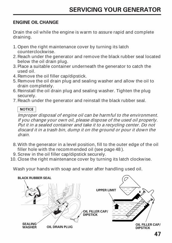
ENGINE OIL CHANGE
UPPER LIMIT
OIL DRAIN PLUGSEALINGWASHER
OIL FILLER CAP/DIPSTICK
OIL FILLER CAP/DIPSTICK
BLACK RUBBER SEAL
Drain the oil while the engine is warm to assure rapid and completedraining.
Improper disposal of engine oil can be harmful to the environment.If you change your own oil, please dispose of the used oil properly.Put it in a sealed container and take it to a recycling center. Do notdiscard it in a trash bin, dump it on the ground or pour it down thedrain.
Wash your hands with soap and water after handling used oil.
With the generator in a level position, fill to the outer edge of the oilfiller hole with the recommended oil (see page ).
Open the right maintenance cover by turning its latchcounterclockwise.Reach under the generator and remove the black rubber seal locatedbelow the oil drain plug.Place a suitable container underneath the generator to catch theused oil.Remove the oil filler cap/dipstick.Remove the oil drain plug and sealing washer and allow the oil todrain completely.Reinstall the oil drain plug and sealing washer. Tighten the plugsecurely.Reach under the generator and reinstall the black rubber seal.
Screw in the oil filler cap/dipstick securely.Close the right maintenance cover by turning its latch clockwise.
1.
2.
3.
4.5.
6.
7.
8.
9.10.
48
06/09/12 12:24:36 31Z25600_048

-
48
SERVICING YOUR GENERATOR
ENGINE OIL RECOMMENDATIONS
SAE Viscosity Grades
AMBIENT TEMPERATURE
Oil is a major factor affecting performance and service life. Use4-stroke automotive detergent oil.
SAE 10W 30 is recommended for general use. Other viscositiesshown in the chart may be used when the average temperature inyour area is within the recommended range.
The SAE oil viscosity and service classification are in the API label onthe oil container. Honda recommends that you use API SERVICEcategory SJ or later oil.
06/09/12 12:24:42 31Z25600_049

49
SERVICING YOUR GENERATOR
AIR CLEANER SERVICE
AIR CLEANERCOVER
COVER SCREW
FOAM AIR FILTER
Remove the foam air filter from the air cleaner cover.
Reinstall the air cleaner cover.
Reinstall the foam air filter in the air cleaner cover.
Check the foam air filter to be sure it is clean and in good condition.
If the foam air filter is dirty, clean it as described on page .Replace the foam air filter if it is damaged.
Operating the engine without an air filter, or with a damaged air filter,will allow dirt to enter the engine, causing rapid engine wear. This typeof damage is not covered by the Distributor’s Limited Warranty.
Open the left maintenance cover by turning its latchcounterclockwise.
Loosen the cover screws and remove the air cleaner cover.
Close the left maintenance cover.
2.
1.
4.
3.
5.
6.
7.
50
06/09/12 12:24:52 31Z25600_050
50
SERVICING YOUR GENERATOR
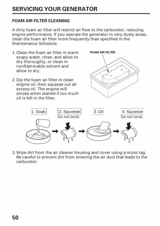
FOAM AIR FILTER CLEANING
FOAM AIR FILTER
A dirty foam air filter will restrict air flow to the carburetor, reducingengine performance. If you operate the generator in very dusty areas,clean the foam air filter more frequently than specified in theMaintenance Schedule.
Clean the foam air filter in warmsoapy water, rinse, and allow todry thoroughly, or clean innonflammable solvent andallow to dry.
Dip the foam air filter in cleanengine oil, then squeeze out allexcess oil. The engine willsmoke when started if too muchoil is left in the filter.
Wipe dirt from the air cleaner housing and cover using a moist rag.Be careful to prevent dirt from entering the air duct that leads to thecarburetor.
1.
2.
3.
3. Oil1. Soak 2. Squeeze 4. SqueezeDo not twist. Do not twist.
06/09/12 12:25:01 31Z25600_051

51
SERVICING YOUR GENERATOR
SEDIMENT CUP CLEANING
SEDIMENT CUP
O-RING
FUEL VALVE LEVER
OFFKEY
OONN
Turn the fuel valve lever to the OFF position and remove the key.Open the left maintenance cover by turning its latchcounterclockwise.
Unscrew the sediment cup and remove it.Remove the O-ring.
Close the left maintenance cover.Reinstall the O-ring and sediment cup.
Wash the sediment cup and O-ring in nonflammable solvent, anddry them thoroughly.
Stop the engine and keep heat,sparks, and flame away.Handle fuel only outdoors.Wipe up spills immediately.
Gasoline is highly flammable andexplosive.
You can be burned or seriouslyinjured when handling fuel.
2.
3.4.
1.
5.
6.7.
06/09/12 12:25:14 31Z25600_052

52
SERVICING YOUR GENERATOR
Recommended spark plugs:
SPARK PLUG SERVICE
SPARK PLUGINSPECTION COVER
COVER SCREW
SPARK PLUG WRENCH
BPR5ES (NGK)W16EPR-U (DENSO)
An incorrect spark plug can cause engine damage.
Open the left maintenance cover by turning its latchcounterclockwise.
Loosen the cover screw and remove the spark plug inspection cover.
Remove the spark plug with a 13/16-inch spark plug wrench(commercially available).
Disconnect the spark plug cap, and remove any dirt from around thespark plug area.
1.
2.
3.
4.
06/09/12 12:25:24 31Z25600_053

-
- -
--
53
SERVICING YOUR GENERATOR
SEALING WASHER
0.028 0.031 in(0.70 0.80 mm)
Inspect the spark plug. Replaceit if the electrodes are worn or ifthe insulator is cracked,chipped or fouled.
Measure the spark plugelectrode gap with a wire-typefeeler gauge. Correct the gap, ifnecessary, by carefully bendingthe side electrode.
The gap should be:
Make sure that the spark plug sealing washer is in good condition,and thread the spark plug in by hand prevent cross-threading.
After the spark plug seats, tighten with a 13/16-inch spark plugwrench to compress the washer.
If reinstalling a used spark plug, tighten 1/8 1/4 turn after the sparkplug seats.If installing a new spark plug, tighten 1/2 turn after the spark plugseats.
A loose spark plug can overheat and damage the engine.Overtightening the spark plug can damage the threads in thecylinder head.
Attach the spark plug cap.
Reinstall the spark plug inspection cover and tighten the coverscrew.
0.028 0.031 in (0.70 0.80 mm)
Close the left maintenance cover.
6.
7.
8.
9.
5.
10.
11.
06/09/12 12:25:37 31Z25600_054

×
×
54
SERVICING YOUR GENERATOR
SPARK ARRESTER SERVICE
SPARK ARRESTER
5 14 mm PAN HEAD SCREW (2)
Install the spark arrester in the reverse order of removal.
The spark arrester must be free of breaks and holes. Replace thespark arrester if it is damaged.
Be careful to avoid damaging the screen.
Use a brush to remove carbon deposits from the spark arresterscreen.
The spark arrester must be serviced every 100 hours to keep itfunctioning as designed.
If the engine has been running, the muffler will be very hot. Allow themuffler to cool before servicing the spark arrester.
Remove the two 5 14 mm pan head screws, and remove the sparkarrester.
1.
2.
3.
06/09/12 12:25:48 31Z25600_055

-
-
-
55
SERVICING YOUR GENERATOR
BATTERY SERVICE
Emergency Procedures
Eyes
Skin
Swallowing
Your generator’s engine charging system charges the battery whilethe engine is running. However, if the generator is only usedperiodically, the battery must be charged monthly to maintain thebattery service life.
The battery contains sulfuric acid(electrolyte) which is highlycorrosive and poisonous. Gettingelectrolyte in your eyes or on yourskin can cause serious burns.
Wear protective clothing and eyeprotection when working near thebattery.KEEP CHILDREN AWAY FROM THEBATTERY.
Flush with water from a cup or other container for at leastfifteen minutes. (Water under pressure can damage the eye.)Immediately call 911 (USA only) or a physician.
Remove contaminated clothing. Flush the skin with largequantities of water. Call a physician immediately.
Drink water or milk. Call your local Poison ControlCenter (USA only) or a physician immediately.
06/09/12 12:25:58 31Z25600_056

56
SERVICING YOUR GENERATOR
Battery Removal
WARNING:Wash hands after handling.
COVER SCREW
HANDLE HANDLE LOCK LEVER
BATTERY MAINTENANCE COVER
Battery posts, terminals and related accessories containlead and lead compounds.
Lift handle upward. Lock levers will lock and secure handle intoplace.
Loosen the cover screw and remove the battery maintenance cover.
1.
2.
06/09/12 12:26:05 31Z25600_057

- -+
+
+
-
57
SERVICING YOUR GENERATOR
POSITIVE ( ) CABLE
NEGATIVE ( ) CABLE
BATTERY STRAP
Remove the negative ( ) cable from the battery negative ( )terminal, then remove the positive ( ) cable from the batterypositive ( ) terminal.
Unhook the battery strap from the bottom hook of the generator.
Remove the battery from the battery tray.
3.
4.
5.
06/09/12 12:26:12 31Z25600_058

- -+
+ +
-
58
SERVICING YOUR GENERATOR
Battery Charging
Battery Installation
The battery gives off explosivehydrogen gas during normaloperation.
A spark or flame can cause thebattery to explode with enoughforce to kill or seriously hurt you.
Wear protective clothing and a faceshield, or have a skilled mechanicdo the battery maintenance.
Connect the battery negative ( ) cable to the battery negative ( )terminal and tighten the bolt securely.
Slide the battery boot over the positive ( ) cable and terminal.
Connect the battery positive ( ) cable to the battery positive ( )terminal first and tighten the bolt securely.
Install the battery into the generator.
Clean the outside of the battery and the battery compartment with asolution of baking soda and water.
Connect the battery charger following the manufacturer’sinstructions.
The battery is rated at 11.2 Ah (ampere-hours). Charging currentshould equal 10% of the battery’s ampere-hour rating. A batterycharger should be used that can be adjusted to deliver 1.1 amps.
Charge the battery 5 10 hours.
Install the battery strap.Install the maintenance cover in the reverse order of removal (seepage ).Never operate the generator without the maintenance cover in place,as poor engine and generator performance will result.
1.
2.3.
1.2.
3.4.
5.6.
56
06/09/12 12:26:25 31Z25600_059

59
SERVICING YOUR GENERATOR
FUSE
Specified fuse:
FUSE (15A)
FUSE HOLDER COVER
FUSE (1A)
COVERSCREW
BATTERYMAINTENANCECOVER
In the event of fuse failure, locate the cause of failure and repair beforeyou continue operation. If the fuse continues to fail, discontinuegenerator use and consult an authorized Honda generator dealer.
If the fuse is blown, the starter motor won’t operate.
Turn the engine switch OFF and remove the key before checking orreplacing the fuse.
1 A, 15 A
Replace the fuse with afuse of the same type andrating.
Remove the fuse holder coverand pull the fuse out.
Never operate the generator without the maintenance cover in place,as poor engine and generator performance will result.
Loosen the cover screw andremove the batterymaintenance cover.
Never use a fuse with adifferent rating from thatspecified. Serious damage tothe electrical system or firemay result.
Install the fuse holder cover and the battery maintenance cover inthe reverse order of removal (see page ).
1.
2.
3.
4.
5.56
06/09/12 12:26:40 31Z25600_060

60
STORAGE PREPARATION
Cleaning
Fuel
STORAGE
Proper storage preparation is essential for keeping your generatortrouble-free and looking good. The following steps will help to keeprust and corrosion from impairing your generator’s function andappearance, and will make the engine easier to start when you use thegenerator again.
Wipe the generator with a moist cloth. After the generator has dried,touch up any damaged paint, and coat other areas that may rust with alight film of oil.
Gasoline will oxidize and deteriorate in storage. Old gasoline willcause hard starting, and it leaves gum deposits that clog the fuelsystem. If the gasoline in your generator deteriorates during storage,you may need to have the carburetor and other fuel systemcomponents serviced or replaced.
You can extend fuel storage life by adding a gasoline stabilizer that isformulated for that purpose, or you can avoid fuel deteriorationproblems by draining the fuel tank and carburetor.
The does not cover fuel system damage orengine performance problems resulting from neglected storagepreparation.
The length of time that gasoline can be left in your fuel tank andcarburetor without causing functional problems will vary with suchfactors as gasoline blend, your storage temperatures, and whether thefuel tank is partially or completely filled. The air in a partially filled fueltank promotes fuel deterioration. Very warm storage temperaturesaccelerate fuel deterioration. Fuel deterioration problems may occurwithin a few months, or even less depending on the gasolineformulation in your area.
Distributor’s Limited Warranty
06/09/12 12:26:50 31Z25600_061

61
STORAGE
Adding a Gasoline Stabilizer to Extend Fuel Storage Life
When adding a gasoline stabilizer, fill the fuel tank with fresh gasoline.If only partially filled, air in the tank will promote fuel deteriorationduring storage. If you keep a container of gasoline for refueling, besure that it contains only fresh gasoline.
Add fuel stabilizer following manufacturer’s instructions.
After adding a fuel stabilizer, run the engine outdoors for 10 minutesto be sure that treated gasoline has replaced the untreated gasolinein the carburetor.
Stop the engine, and turn the fuel valve lever to the OFF position.
1.
2.
3.
06/09/12 12:26:56 31Z25600_062

62
STORAGE
Draining the Fuel Tank and Carburetor
DRAIN SCREW
Gasoline is highly flammable andexplosive.
You can be burned or seriouslyinjured when handling fuel.
Stop the engine and keep heat,sparks, and flame away.Handle fuel only outdoors.Wipe up spills immediately.
Open the right maintenance cover by turning its latchcounterclockwise.
Place a suitable gasoline containerbelow the carburetor drain hose.
After all the fuel has drained into thecontainer, tighten the drain screwsecurely.
Loosen the carburetor drain screwand drain the gasoline from thecarburetor and tank.
Remove the sediment cup and empty it.
Reinstall the sediment cup. (see page )
Move the fuel valve to the ONposition.
1.
2.
3.
4.
5.
6.
7. 51
06/09/12 12:27:08 31Z25600_063

-
63
STORAGE
Engine Oil
Change the engine oil (see page ).
Pour a tablespoon (5 10 cc) of clean engine oil into the cylinder.
Remove the spark plug (see page ).
Pull the starter rope several times to distribute the oil in the cylinder.
Reinstall the spark plug.
Slowly pull the starter grip until resistance is felt. At this point, thepiston is coming up on its compression stroke and both the intakeand exhaust valves are closed. Storing the engine in this positionwill help to protect it from internal corrosion. Return the starter gripgently.
1.
2.
3.
6.
5.
4.
47
52
06/09/12 12:27:17 31Z25600_064

64
STORAGE
STORAGE PRECAUTIONS
REMOVAL FROM STORAGE
If your generator will be stored with gasoline in the fuel tank andcarburetor, it is important to reduce the hazard of gasoline vaporignition.
If the cylinder was coated with oil during storage preparation, theengine may smoke briefly at startup. This is normal.
If the fuel was drained during storage preparation, fill the tank withfresh gasoline. If you keep a container of gasoline for refueling, besure that it contains only fresh gasoline. Gasoline oxidizes anddeteriorates over time, causing hard starting.
Check your generator as described in the BEFORE OPERATION chapterof this manual.
Fully charge the battery. Recharge the battery once a month (see page).
Do not use sheet plastic as a dust cover. A nonporous cover will trapmoisture around the generator, promoting rust and corrosion.
With the engine and exhaust system cool, cover the generator to keepout dust. A hot engine and exhaust system can ignite or melt somematerials.
Place the generator on a level surface. Tilting can cause fuel or oilleakage.
Unless all fuel has been drained from the fuel tank, leave the fuel valvein the OFF position to reduce the possibility of leakage.
If possible, avoid storage areas with high humidity, because thatpromotes rust and corrosion.
Also avoid any area with a spark-producing electric motor, or wherepower tools are operated.
Select a well ventilated storage area away from any appliance thatoperates with a flame, such as a furnace, water heater, or clothes dryer.
58
06/09/12 12:27:30 31Z25600_065

65
TRANSPORTING
If the generator has been running, allow the engine to cool for at least15 minutes before loading the generator on the transport vehicle. Ahot engine and exhaust system can burn you and can ignite somematerials.
Keep the generator level when transporting to reduce the possibility offuel leakage. Move the fuel valve to the OFF position.
When using ropes or tie-down straps to secure the generator fortransportation, be sure to only use the frame bars as attachmentpoints. Do not fasten ropes or straps to any portions of the generatorbody or the folding transport handle.
06/09/12 12:27:35 31Z25600_066

66
TAKING CARE OF UNEXPECTED PROBLEMS
ENGINE WILL NOT START
Possible Cause CorrectionFuel valve lever OFF.Engine switch OFF.Out of fuel.Bad fuel; generator storedwithout treating or draininggasoline, or refueled with badgasoline.Low oil level caused Oil Alertto stop engine.
Spark plug faulty, fouled, orimproperly gapped.Spark plug wet with fuel(flooded engine).Fuel filter restricted,carburetor malfunction,ignition malfunction, valvesstuck, etc.
Turn lever ON.Turn engine switch to ON.Refuel (p. 44).Drain fuel tank and carburetor(p. 62).Refuel with fresh gasoline(p. 44).Add oil (p. 46).Turn engine switch to OFF andrestart the engine.Gap, or replace spark plug(p. 52).Dry and reinstall spark plug.
Take the generator to anauthorized Honda servicingdealer, or refer to the shopmanual.
06/09/12 12:27:41 31Z25600_067

67
TAKING CARE OF UNEXPECTED PROBLEMS
ENGINE LACKS POWER
Possible cause CorrectionAir filter restricted.Bad fuel; generator storedwithout treating or draininggasoline, or refueled with badgasoline.Fuel filter restricted,carburetor malfunction,ignition malfunction, valvesstuck, etc.
Clean or replace air filter (p. 49).Drain fuel tank and carburetor(p. 62).Refuel with fresh gasoline(p. 44).Take the generator to anauthorized Honda servicingdealer, or refer to the shopmanual.
06/09/12 12:27:48 31Z25600_068

68
TAKING CARE OF UNEXPECTED PROBLEMS
NO POWER AT THE RECEPTACLES
Possible Cause Correction
Check AC load. Stop and restartthe engine.Check the cooling air inlet. Stopand restart the engine.Check AC load and reset circuitprotector(s) (p. 14).Replace or repair power tool orappliance.Stop and restart the engine.Take the generator to anauthorized Honda servicingdealer, or refer to the shopmanual.
Output indicator is OFF, andoverload indicator is ON.
Circuit protector(s) tripped.
Faulty power tool orappliance.
Faulty generator.
06/09/12 12:27:54 31Z25600_069

69
TECHNICAL INFORMATION
TECHNICAL & CONSUMER INFORMATION
FRAME SERIAL NUMBER
Serial Number Location
Record the frame serial number in the space below. You will need thisserial number when ordering parts, and when making technical orwarranty inquiries.
Frame serial number:
Date purchased:
06/09/12 12:28:01 31Z25600_070

70
TECHNICAL & CONSUMER INFORMATION
Carburetor Modification for High Altitude Operation
At high altitude, the standard carburetor air-fuel mixture will be toorich. Performance will decrease, and fuel consumption will increase. Avery rich mixture will also foul the spark plug and cause hard starting.Operation at an altitude that differs from that at which this engine wascertified, for extended periods of time, may increase emissions.
High altitude performance can be improved by specific modificationsto the carburetor. If you always operate your generator at altitudesabove 5,000 feet (1,500 meters), have your authorized Honda servicingdealer perform this carburetor modification. This engine, whenoperated at high altitude with the carburetor modifications for highaltitude use, will meet each emission standard throughout its usefullife.
Even with carburetor modification, engine horsepower will decreaseabout 3.5% for each 1,000-foot (300-meter) increase in altitude. Theeffect of altitude on horsepower will be greater than this if nocarburetor modification is made.
When the carburetor has been modified for high altitude operation,the air/fuel mixture will be too lean for low altitude use. Operation ataltitudes below 5,000 feet (1,500 meters) with a modified carburetormay cause the engine to overheat and result in serious engine damage.For use at low altitudes, have your servicing dealer return thecarburetor to original factory specifications.
06/09/12 12:28:08 31Z25600_071

71
TECHNICAL & CONSUMER INFORMATION
Emission Control System Information
Source of Emissions
The U.S. and California Clean Air Acts
Tampering and Altering
The combustion process produces carbon monoxide, oxides ofnitrogen, and hydrocarbons. Control of hydrocarbons and oxides ofnitrogen is very important because, under certain conditions, theyreact to form photochemical smog when subjected to sunlight. Carbonmonoxide does not react in the same way, but it is toxic.
Honda uses lean carburetor settings and other systems to reduce theemissions of carbon monoxide, oxides of nitrogen, and hydrocarbons.
EPA and California regulations require all manufacturers to furnishwritten instructions describing the operation and maintenance ofemission control systems.
The following instructions and procedures must be followed in orderto keep the Honda engine emissions within the emission standards.
Tampering with or altering the emission control system may increaseemissions beyond the legal limit. Among those acts that constitutetampering are:
Removal or alteration of any part of intake, fuel, or exhaust systems.
Altering or defeating the governor linkage or speed-adjustingmechanism to cause the engine to operate outside its designparameters.
06/09/12 12:28:18 31Z25600_072

72
TECHNICAL & CONSUMER INFORMATION
Problems That May Affect Emissions
Replacement Parts
Maintenance
If you are aware of any of the following symptoms, have your engineinspected and repaired by your authorized Honda servicing dealer.
Hard starting or stalling after starting.
Rough idle.
Misfiring or backfiring under load.
Afterburning (backfiring).
Black exhaust smoke or high fuel consumption.
The emission control systems on your new Honda engine weredesigned, built, and certified to conform with EPA and Californiaemission regulations. We recommend the use of genuine Honda partswhenever you have maintenance done. These original-designreplacement parts are manufactured to the same standards as theoriginal parts, so you can be confident of their performance. The useof replacement parts that are not of the original design and qualitymay impair the effectiveness of your emission control system.
A manufacturer of an aftermarket part assumes the responsibility thatthe part will not adversely affect emission performance. Themanufacturer or rebuilder of the part must certify that use of the partwill not result in a failure of the engine to comply with emissionregulations.
Follow the Maintenance Schedule on page . Remember that thisschedule is based on the assumption that your machine will be usedfor its designed purpose. Sustained high-load or high-temperatureoperation, or use in dusty conditions, will require more frequentservice.
43
06/09/12 12:28:26 31Z25600_073

-
-
-
73
TECHNICAL & CONSUMER INFORMATION
Air Index
An Air Index Information hang tag/label is applied to engines certifiedto an emission durability time period in accordance with therequirements of the California Air Resources Board.
The bar graph is intended to provide you, our customer, the ability tocompare the emissions performance of available engines. The lowerthe Air Index, the less pollution.
The durability description is intended to provide you with informationrelating to the engine’s emission durability period. The descriptiveterm indicates the useful life period for the engine’s emission controlsystem. See your Emission Control System Warranty for additionalinformation.
Descriptive TermModerate
Intermediate
Extended
Applicable to Emissions Durability Period50 hours (0 65 cc)
125 hours (greater than 65 cc)125 hours (0 65 cc)250 hours (greater than 65 cc)300 hours (0 65 cc)500 hours (greater than 65 cc)
The Air Index Information hang tag must remain on the generator untilit is sold. Remove the hang tag before operating the generator.
06/09/12 12:28:38 31Z25600_074

±
× ×
±
- 〈 〉
- -
*
*
74
TECHNICAL & CONSUMER INFORMATION
Tuneup Specifications
ITEM SPECIFICATION
Dimensions
Engine
Generator
MAINTENANCE
Specifications
EASJEU6500is
Spark plug gapValve clearance(cold)
Other specifications No other adjustments needed.EX: 0.20 0.02 mm
6.5 kVA5.5 kVA
45.8/22.9 A60 Hz
120/240 VA
3.5 2.5 in (88 64 mm)
Model (Type)
Length[Handle in up position]WidthHeight[Handle in up position]Dry weight
ModelEngine TypeDisplacementBore x StrokeCompression RatioEngine SpeedCooling SystemIgnition SystemOil CapacityFuel Tank CapacitySpark Plug
TypeRated voltageRated frequency
AC output Rated AmpereRated OutputMaximum Output
IN: 0.15 0.02 mm
W16EPR-U (DENSO)BPR5ES (NGK)
4.36 US gal (16.5 )1.18 US qt (1.12 )
Full transistorForced air
8.0:1
23.7 cu-in (389 cm )
GX390K1
254 lbs (115 kg)28.2 in (716 mm)27.5 in (699 mm)26.5 in (672 mm)
47.0 in (1,195 mm)33.5 in (850 mm)
4-stroke, overhead valve, single cylinder
2,400 3,600 rpm
Refer to page: 52See your authorizedHonda dealer
]
]
[
[
EcoThrottle ON
0.028 0.031 in (0.70 0.80 mm)
Specifications may vary according to the types, and are subject tochange without notice.
Without battery
Power product description code
06/09/12 12:28:55 31Z25600_075

75
TECHNICAL & CONSUMER INFORMATION
Wiring Diagram
06/09/12 12:29:32 31Z25600_076

76
TECHNICAL & CONSUMER INFORMATION
CONSUMER INFORMATION
Dealer Locator Information
Honda Publications
Shop Manual
Parts Catalog
To find an authorized Honda Servicing Dealer anywhere in the UnitedStates:
This manual covers complete maintenance and overhaul procedures.It is intended to be used by a skilled technician.Available through your Honda dealer or through Helm Inc. at 1 888-292-5395 or visit www.hondapowerequipment.com
This manual provides complete, illustrated parts lists. Availablethrough your Honda dealer.
Visit our website:www.hondapowerequipment.com
06/09/12 12:29:41 31Z25600_077

77
TECHNICAL & CONSUMER INFORMATION
Customer Service Information
Honda Power Equipment dealership personnel are trainedprofessionals. They should be able to answer any question you mayhave. If you encounter a problem that your dealer does not solve toyour satisfaction, please discuss it with the dealership’s management.The Service Manager or General Manager can help. Almost allproblems are solved in this way.
If you are dissatisfied with the decision made by the dealership’smanagement, contact the Honda Power Equipment CustomerRelations Office. You can write:
American Honda Motor Co., Inc.Power Equipment DivisionCustomer Relations Office4900 Marconi DriveAlpharetta, Georgia 30005-8847
When you write or call, please give us this information:
Model and serial numbers (see page )Name of the dealer who sold the generator to youName and address of the dealer who services your generatorDate of purchaseYour name, address, and telephone numberA detailed description of the problem
Or telephone: (770) 497-6400 8:30 am to 7:00 pm ET
69
06/09/12 12:29:48 31Z25600_078

78
ASSEMBLY
SAFETY
The Importance of Proper Assembly
Improper assembly can cause anunsafe condition that can lead toserious injury or death.
Follow the procedures andprecautions in the assemblyinstructions carefully.
Proper assembly is essential to operator safety and the reliability ofthe machine. Any error or oversight made by the person assemblingand servicing a unit can easily result in faulty operation, damage to themachine, or injury to the operator.
Some of the most important safety precautions are given below.However, we cannot warn you of every conceivable hazard that canarise in performing this assembly. Only you can decide whether or notyou should perform a given task.
Failure to properly followinstructions and precautions cancause you to be seriously hurt orkilled.
Follow the procedures andprecautions in this manual carefully.
06/09/12 12:29:55 31Z25600_079

□
□
□
□
79
ASSEMBLY
Important Safety Precautions
Carbon monoxide poisoning from engine exhaust.
Injury from moving parts.
Burns from hot parts.
Make sure you have a clear understanding of all basic shop safetypractices and that you are wearing appropriate clothing and safetyequipment. When performing this assembly, be especially careful ofthe following:
Make sure the engine is off before you begin any maintenance orrepairs. This will help eliminate several potential hazards:
Read the instructions before you begin and be sure you havethe tools and skills required to perform the tasks safely.
Be sure there is adequate ventilation whenever you run theengine.
Do not run the engine unless the instruction tells you to do so.Even then, keep your hands, fingers, and clothing away. Do notrun the engine when any protective guard or shield is removed.
Let the engine and exhaust system cool before touching.
To reduce the possibility of a fire or explosion, be careful whenworking around gasoline or batteries. Use only a nonflammablesolvent, not gasoline, to clean parts. Keep all cigarettes, sparks, andflames away from all fuel-related parts.
06/09/12 12:30:04 31Z25600_080

××
×
80
ASSEMBLY
ASSEMBLY
Unpacking
Loose Parts
Tools Required:
Compare the loose parts with the inventory list below.
Remove the generator and loose parts box from the carton.
Check all loose parts against the following list. Contact your dealer ifany of the loose parts shown below are not included with yourgenerator.
14 mm wrench (2), 10 mm wrench or Phillips headscrewdriver for battery connections, pliers(not included)
1.
2.
Ref. No.12345678
Ref. No.9101112131415
Qty.2228442
DescriptionSpring WasherHandle holder bolt
6 mm Cap nut
DescriptionWheelAxleHandle assy.StandRear pipe20 mm Washer
12 mm Washer
Qty.21121222
6 30 mm Flange bolt8 16 mm Flange bolt8 mm Washer (t = 6 mm)8 mm Washer (t = 2.3 mm)
4.0 28 mm Cotter pin
06/09/12 12:30:18 31Z25600_081

- - -
×
×
×
×
×
81
ASSEMBLY
Wheel Kit Installation
TORQUE:
AXLE
WHEEL (2)
8 16 mm FLANGE BOLT (4)
8 16 mmFLANGE BOLT (4)
STAND
20 mm WASHER
4.0 28 mmCOTTER PIN (2)
SSHHOORRTTEERR
8 mm WASHER (4)(t = 6 mm)
8 mm WASHER (4)(t = 2.3 mm)
17 22 lbf·ft (24 29 N·m , 2.4 3.0 kgf·m)
Install the two wheels on the axle shaft using the washers and cotterpins.
If the wheel kit is not installed, it may be possible for dirt and debris tobe drawn into the generator air intake causing possible generatordamage. Always operate the generator with the wheel kit installed.
Do not operate the generator without the wheel kit installed. Thewheel kit provides an air space between the ground and the generatorair intake.
Install the axle assembly on the generator using four 8 mm washersand 8 16 mm flange bolts.
Install the two stands on the under frame using four 8 mm washersand 8 16 mm flange bolts.
1.
2.
3.
06/09/12 12:30:28 31Z25600_082

- - -
82
ASSEMBLY
Handle Installation
To extend handle:
TORQUE:
SPRING WASHER (2)
12 mm WASHER (2)
HANDLE ASSEMBLY
HANDLE HANDLE LOCK LEVER
HANDLE HOLDER BOLT (2)
17 22 lbf·ft (24 29 N·m , 2.4 3.0 kgf·m)
Operation must be checked after attaching a handle.
Raise handle to horizontal position. The handle will click into placewhen locked.
Install the handle assembly on the generator upper frame using the12 mm washers, spring washers and handle holder bolts.
06/09/12 12:30:36 31Z25600_083

- - -
×
×
83
ASSEMBLY
Rear Bar Installation
TORQUE:
REAR BAR
CAP NUT (2)
6 30 mm BOLT (2)
17 22 lbf·ft (24 29 N·m , 2.4 3.0 kgf·m)
Install the rear bar on the generator frame using the two 6 30 mmbolts and two cap nuts.
06/09/12 12:30:41 31Z25600_084
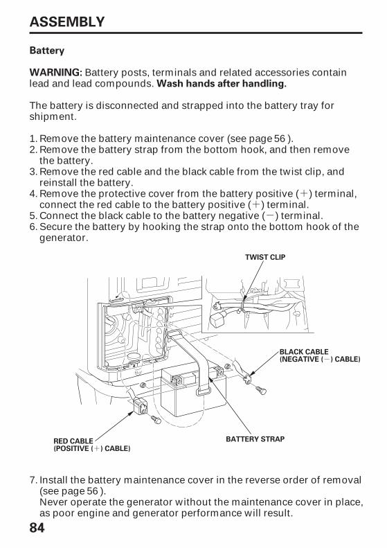
-
++
+
-
84
ASSEMBLY
WARNING:Wash hands after handling.
Battery
TWIST CLIP
BATTERY STRAPRED CABLE(POSITIVE ( ) CABLE)
BLACK CABLE(NEGATIVE ( ) CABLE)
Never operate the generator without the maintenance cover in place,as poor engine and generator performance will result.
Install the battery maintenance cover in the reverse order of removal(see page ).
Secure the battery by hooking the strap onto the bottom hook of thegenerator.
Connect the black cable to the battery negative ( ) terminal.
Remove the protective cover from the battery positive ( ) terminal,connect the red cable to the battery positive ( ) terminal.
Remove the red cable and the black cable from the twist clip, andreinstall the battery.
Remove the battery strap from the bottom hook, and then removethe battery.
Remove the battery maintenance cover (see page ).
The battery is disconnected and strapped into the battery tray forshipment.
Battery posts, terminals and related accessories containlead and lead compounds.
5.6.
1.2.
3.
4.
7.56
56
06/09/12 12:30:54 31Z25600_085

85
ASSEMBLY
Engine Oil
WITHOUT OIL
Fuel
SAE Viscosity Grades
AMBIENT TEMPERATURE
OIL FILLER HOLE
UPPER LIMIT
OIL FILLER CAP/DIPSTICK
The generator is shippedin the engine.
Refer to page .
Place the generator on a levelsurface. Open the rightmaintenance cover by turningits latch counterclockwise.Add enough of therecommended oil to bring theoil level to the top of the oilfiller neck.
Use a 4-stroke motor oil thatmeets the requirements forAPI service classification SJor later.
SAE 10W-30 is recommendedfor general, all-temperatureuse. Other viscosities in thechart may be used when thetemperature in your area iswithin the indicated range.
Do not overfill engine oil. Ifthe engine is overfilled, theexcess oil may gettransferred to the air cleanerhousing and air filter.
Close the right maintenancecover by turning its latchclockwise.
60
06/09/12 12:31:07 31Z25600_086

86
ASSEMBLY
BEFORE OPERATION
Battery Voltage
CONTROLS & FEATURES
GENERATOR SAFETY
OPERATION
STARTING THE ENGINE
STOPPING THE ENGINE
Check the battery voltage with the i-Monitor (see page ).
The battery voltage should be 12.3 V or more.
If the battery voltage is low, charge the battery until the battery voltagewill be 12.3 V or more.
(page )
(page )
Before using your generator, you should become familiar withinformation contained in the following chapters and sections:
(page )
(page )
(page )
10
6
26
27
31
21
06/09/12 12:31:19 31Z25600_087

87
OPTIONAL PARTS
Remote Control Kit
KNOCKOUT
PLUG
BATTERY MAINTENANCE COVER
Remove the plug from the 6-pin connector.
View the back of the maintenance cover and locate the knockoutnear the top center of the cover. Carefully remove the knockout.
Remove the battery maintenance cover (see page ).1.
2.
3.
56
06/09/12 12:31:27 31Z25600_088

88
OPTIONAL PARTS
CABLE TIE
REMOTECONTROL CABLE
REMOTE CONTROL BOX
GROMMET
PLUG
BATTERY MAINTENANCECOVER
REMOTE CONTROLCABLE
Plug the remote control cable into the 6-pin connector.
To avoid accidentally unplugging the remote control cable, securethe cable to the generator frame with a cable tie as shown.
When the remote control is notbeing used, replace the plug on theconnector.
Pass the remote control cable through the supplied wire grommetand fit the grommet into the battery maintenance cover knockout.
Install the battery maintenance cover and tighten the cover screw.
Never operate the generatorwithout the battery maintenancecover in place, as poor engine andgenerator performance will result.
7.
4.
5.6.
06/09/12 12:31:36 31Z25600_089

×
- - -
×
89
OPTIONAL PARTS
Hanger Kit
TORQUE:
HANGER 8 16 mm FLANGE BOLT (4)
HANGER
PROTECTOR FILM
HANGERBRACKET (2)
Protect the fuel tank and frame pipe with the protector films duringinstallation of the hanger.
Insert the bracket installation part at one end of the hanger into theclearance between the frame pipe and fuel tank.
Slide the hanger and insert another bracket installation part of thehanger into the gap between the frame pipe and fuel tank on theother side.
Slide the hanger along the frame pipe to align the center of thehanger with the recessed part on the rear side of the fuel tank.Install the hanger brackets on both ends of the hanger and tightenthe 8 16 mm flange bolts securely.
17 22 lbf·ft (24 29 N·m , 2.4 3.0 kgf·m)
1.
2.
3.
06/09/12 12:31:46 31Z25600_090

90
INDEX
A
B
C
E
...................................................................................AC Applications . 35..........................................................................AC Circuit Protectors . 14
...................................................................................AC OPERATION . 33....................................................................AC Receptacle Selection . 36
......................................................................AIR CLEANER SERVICE . 49...............................................................................................Air Index . 73
...............................................ARE YOU READY TO GET STARTED? . 24....................................................................................ASSEMBLY . 78, 80
..................................................................................................Battery . 86...............................................................Battery Maintenance Cover . 25
.............................................................................BATTERY SERVICE . 55..........................................................................BEFORE OPERATION . 24
...................................................................Carbon Monoxide hazards . 6......................Carburetor Modification for High Altitude Operation . 70
................................................................................Check the Engine . 25...............................................................................................Cleaning . 60
..........................................COMPONENT & CONTROL LOCATIONS . 10.................................Connections to a Building’s Electrical System . 39
..............................................................CONSUMER INFORMATION . 76..........................................................................................CONTROLS . 12
..................................................................CONTROLS & FEATURES . 10..........................................................Customer Service Information . 77
...........................................................................EcoThrottle Switch . 13.................................................................ECOTHROTTLE SYSTEM . 38
.........................................................................Electric Shock Hazards . 7..............................................Emission Control System Information . 71
.....................................................................ENGINE LACKS POWER . 67.............................................................................................Engine oil . 63
.........................................................................ENGINE OIL CHANGE . 47................................................................ENGINE OIL LEVEL CHECK . 46
..................................................ENGINE OIL RECOMMENDATIONS . 48.....................................................................................Engine Switch . 12
.................................................................ENGINE WILL NOT START . 66
TM
TM
06/09/12 12:31:53 31Z25600_091

91
INDEX
F
G
H
I
K
L
...........................................................................................FEATURES . 17..........................................................................Fire and Burn Hazards . 7
....................................................................................Folding Handle . 15...........................................................FOAM AIR FILTER CLEANING . 50
.......................................................................................................Fuel . 60..........................................................................................Fuel Gauge . 23
.............................................................FUEL RECOMMENDATIONS . 45..................................................................................Fuel Valve Lever . 12
....................................................................................................FUSE . 59
..........................................................................GENERATOR SAFETY . 6.................................................................................Ground Terminal . 17
..............................................................................Handle Installation . 83............................................................................................Hanger Kit . 89
.............................................................................Honda Publications . 76
...........................................................................................i-Monitor . 20................................................IMPORTANT SAFETY INFORMATION . 6
............................................................Important Safety Precautions . 79...................................................................................................INDEX . 90
..............................................IS YOUR GENERATOR READY TO GO . 24
...........................................................................................Knowledge . 24
..........................................................................................Loose Parts . 80
TM
06/09/12 12:32:02 31Z25600_092

92
INDEX
M
O
Q
R
N
.............................................................................Maintenance Cover . 16....................................................................MAINTENANCE SAFETY . 42
..............................................................MAINTENANCE SCHEDULE . 43
..................................................NO POWER AT THE RECEPTACLES . 68
..............................................................................Oil Alert Indicator . 19.........................................................................................OPERATION . 26
.......................................................................Operator Responsibility . 6..............................................................................OPTIONAL PARTS . 87
..................................................................................Output Indicator . 18..............................................................................Overload Indicator . 18
........................QUICK REFERENCE INFORMATION . Inside back cover
...........................................................................Rear Bar Installation . 83........................................................................................Ricoil Starter . 13
..........................................................................................REFUELING . 44...................................................................................Refuel With Care . 8
.............................................................................Remote Control Kit . 87..............................................................REMOVAL FROM STORAGE . 64
06/09/12 12:32:08 31Z25600_093

93
INDEX
S
T
U
V
W
.....................................................................Voltage Selector Switch . 14
..........................................................................Wheel Kit Installation . 81...................................................................................Wiring Diagram . 75
...................................................SAFE OPERATING PRECAUTIONS . 26................................................................................................SAFETY . 78
................................................................SAFETY LABEL LOCATIONS . 9..............................................................................Safety Precautions . 42
...............................................................SEDIMENT CUP CLEANING . 51.....................................................................Serial Number Location . 69
.......................................................SERVICING YOUR GENERATOR . 41..............................................................SPARK ARRESTER SERVICE . 54
.......................................................................SPARK PLUG SERVICE . 52........................................................................Special Requirements . 40
......................................................................................Specifications . 74.............................................................................STAND BY POWER . 39
....................................................................STARTING THE ENGINE . 27
....................................................................STOPPING THE ENGINE . 31............................................................................................STORAGE . 60
.................................................................STORAGE PRECAUTIONS . 64..................................................................STORAGE PREPARATION . 60
...................................................................................System Ground . 39
.................................TAKING CARE OF UNEXPECTED PROBLEMS . 66....................................TECHNICAL & CONSUMER INFORMATION . 69
...............................................................TECHNICAL INFORMATION . 69............................................THE IMPORTANCE OF MAINTENANCE . 41
................................................The Importance of Proper Assembly . 78...................................................................................TRANPORTING . 65
............................................................................................Unpacking . 80
06/09/12 12:32:16 31Z25600_094

94
MEMO
06/09/12 12:32:19 31Z25600_095

06/09/12 12:32:20 31Z25600_096

06/09/12 12:32:22 31Z25600_097

- -
QUICK REFERENCE INFORMATION
Fuel
Spark Plug
Battery
Maintenance
Type
Type
Part Number
Subsequent
Regular unleaded gasoline witha pump octane rating of 86 orhigher
Check engine oil level.Check air filter.Change engine oil.See Maintenance Schedule(page 43)
0.028 0.031 in (0.70 0.80 mm)
NGK:
Honda P/N:Yuasa Model:
BPR5ESW16EPR-UDENSO:
31500-MCR-D02YTZ14S
Electrode Gap
First 20 hours
Before each use
06/09/12 12:32:28 31Z25600_098
31Z2560000X31-Z25-6000
o2006 Honda Motor Co., Ltd.-All Rights ReservedN2eY11000.2006.09
Printed in Japan
Owner’s ManualGENERATOR
EU6500is
Black DIC F10131Z25600 00X31-Z25-6000 EU6500is
See page 78 for instructionson assembling your generator.


