47
Generic Host Device Management Supports Management Module SM-GHO1000 Titlepage

Generic Host
Device Management
Supports Management Module SM-GHO1000
Titlep
age
D e v i c e M a n a g e m e n t Page 2 G e n e r i c H o s t

D e v i c e M a n a g e m e n t Page 2 G e n e r i c H o s t
Copyright NoticeDocument 9031570-05. Copyright © May 2002 Aprisma Management Technologies, Inc. All rights reserved worldwide. Use, duplication, or disclosure by the United States government is subject to the restrictions set forth in DFARS 252.227-7013(c)(1)(ii) and FAR 52.227-19.Liability DisclaimerAprisma Management Technologies, Inc. (“Aprisma”) reserves the right to make changes in specifications and other information contained in this document without prior notice. In all cases, the reader should contact Aprisma to inquire if any changes have been made.
The hardware, firmware, or software described in this manual is subject to change without notice.
IN NO EVENT SHALL APRISMA, ITS EMPLOYEES, OFFICERS, DIRECTORS, AGENTS, OR AFFILIATES BE LIABLE FOR ANY INCIDENTAL, INDIRECT, SPECIAL, OR CONSEQUENTIAL DAMAGES WHATSOEVER (INCLUDING BUT NOT LIMITED TO LOST PROFITS) ARISING OUT OF OR RELATED TO THIS MANUAL OR THE INFORMATION CONTAINED IN IT, EVEN IF APRISMA HAS BEEN ADVISED OF, HAS KNOWN, OR SHOULD HAVE KNOWN, THE POSSIBILITY OF SUCH DAMAGES.
Trademark, Service Mark, and Logo InformationSPECTRUM, IMT, and the SPECTRUM IMT/VNM logo are registered trademarks of Aprisma Management Technologies, Inc., or its affiliates. APRISMA, APRISMA MANAGEMENT TECHNOLOGIES, the APRISMA MANAGEMENT TECHNOLOGIES logo, MANAGE WHAT MATTERS, DCM, VNM, SpectroGRAPH, SpectroSERVER, Inductive Modeling Technology, Device Communications Manager, SPECTRUM Security Manager, and Virtual Network Machine are unregistered trademarks of Aprisma Management Technologies, Inc., or its affiliates. For a complete list of Aprisma trademarks, service marks, and trade names, go tohttp://www.aprisma.com/manuals/trademark-list.htm.
All referenced trademarks, service marks, and trade names identified in this document, whether registered or unregistered, are the intellectual property of their respective owners. No rights are granted by Aprisma Management Technologies, Inc., to use such marks, whether by implication, estoppel, or otherwise. If you have comments or concerns
about trademark or copyright references, please send an e-mail to [email protected]; we will do our best to help.
Restricted Rights Notice(Applicable to licenses to the United States government only.)This software and/or user documentation is/are provided with RESTRICTED AND LIMITED RIGHTS. Use, duplication, or disclosure by the government is subject to restrictions as set forth in FAR 52.227-14 (June 1987) Alternate III(g)(3) (June 1987), FAR 52.227-19 (June 1987), or DFARS 52.227-7013(c)(1)(ii) (June 1988), and/or in similar or successor clauses in the FAR or DFARS, or in the DOD or NASA FAR Supplement, as applicable. Contractor/manufacturer is Aprisma Management Technologies, Inc. In the event the government seeks to obtain the software pursuant to standard commercial practice, this software agreement, instead of the noted regulatory clauses, shall control the terms of the government's license.Virus DisclaimerAprisma makes no representations or warranties to the effect that the licensed software is virus-free.
Aprisma has tested its software with current virus-checking technologies. However, because no antivirus system is 100 percent effective, we strongly recommend that you write-protect the licensed software and verify (with an antivirus system in which you have confidence) that the licensed software, prior to installation, is virus-free.
Contact InformationAprisma Management Technologies, Inc.273 Corporate DrivePortsmouth, NH 03801Phone: 603-334-2100U.S. toll-free: 877-468-1448Web site: http://www.aprisma.com
D e v i c e M a n a g e m e n t Page 3 G e n e r i c H o s t
ContentsINTRODUCTION 5
Purpose and Scope ........................................................5Required Reading ...........................................................5Supported Devices..........................................................6The SPECTRUM Model ..................................................6
TASKS 9
DEVICE VIEW 10
Interface Icons ..............................................................11Interface Icon Subviews Menu......................................12Secondary Address Panel ............................................13
DEVICE TOPOLOGY VIEW 14
APPLICATION VIEWS 15
Main Application View...................................................15Supported Applications .................................................16
Common Applications................................................16Device-Specific MIBs.................................................17
LAN Manager Application .............................................18System Configuration View .......................................18Lan Manager Domains View .....................................18Server View ...............................................................19Workstation View.......................................................20
DHCP Application .........................................................21
Parameters-Dhcp App............................................... 21Scope View ............................................................... 22
Wins Application ........................................................... 22System Configuration ................................................ 22Notification................................................................. 23Wins Counters........................................................... 24Wins History .............................................................. 24Wins Pull ................................................................... 25Wins Settings ............................................................ 26
Acs Application ............................................................. 27ACS Server Statistics ................................................ 27ACS If Statistics View................................................ 28MSIDLPM View ......................................................... 30
Ftp Application .............................................................. 32FTP Statistics ............................................................ 32
User Information................................................. 32Traffic Information .............................................. 33Connection Information ...................................... 33
Http Application............................................................. 33HTTP Statistics.......................................................... 34
User Information................................................. 34Traffic Information .............................................. 34Connection Information ...................................... 34
HTTP Requests......................................................... 35General Request Information ............................. 35Client Access Licenses ...................................... 35
HTTP Method Requests............................................ 36

C o n t e n t s C o n t e n t s
D e v i c e M a n a g e m e n t Page 4 G e n e r i c H o s t
HTTP BGI/CGI Requests ..........................................37RipSap Application........................................................38
RIP View....................................................................38SAP View...................................................................39
PERFORMANCE VIEWS 41
CONFIGURATION VIEWS 42
Device Configuration View............................................42
MODEL INFORMATION VIEW 44
INDEX 45

D e v i c e M a n a g e m e n t Page 5 G e n e r i c H o s t
Introduction
This section introduces the SPECTRUM Device Management documentation for the third party PCs and workstations defined herein.
This introduction contains the following topics:
• Purpose and Scope
• Required Reading
• Supported Devices (Page 6)
• The SPECTRUM Model (Page 6)
Purpose and ScopeUse this document as a guide for managing the third party PCs and workstations listed under Supported Devices (Page 6) using SPECTRUM Management Module SM-GHO1000.
This document describes the icons, menus, and views that enable you to remotely monitor,
configure, and troubleshoot the devices through software models in your SPECTRUM database.
Information specific to the SM-GHO1000 is what is primarily included in this document. For general information about device management using SPECTRUM and explanations of SPECTRUM functionality and navigation techniques, refer to the topics listed under Required Reading.
Required ReadingTo use this documentation effectively, you must be familiar with the information covered by the other SPECTRUM online documents listed below.
• Getting Started with SPECTRUM for Operators
• Getting Started with SPECTRUM for Administrators
Note:Note:
For simplicity in this guide, the PCs and workstations are referred to collectively as the devices.
I n t r o d u c t i o n S u p p o r t e d D e v i c e s
D e v i c e M a n a g e m e n t Page 6 G e n e r i c H o s t
• How to Manage Your Network with SPECTRUM
• SPECTRUM Views
• SPECTRUM Menus
• SPECTRUM Icons
• SPECTRUM Software Release Notice
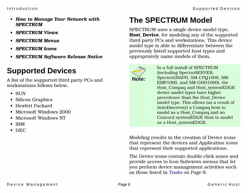
Supported DevicesA list of the supported third party PCs and workstations follows below.
• SUN• Silicon Graphics• Hewlett Packard• Microsoft Windows 2000• Microsoft Windows NT• IBM• DEC
The SPECTRUM ModelSPECTRUM uses a single device model type, Host_Device, for modeling any of the supported third party PCs and workstations. This device model type is able to differentiate between the previously listed supported host types and appropriately name models of them.
Modeling results in the creation of Device icons that represent the devices and Application icons that represent their supported applications.
The Device icons contain double-click zones and provide access to Icon Subviews menus that let you perform device management activities such as those listed in Tasks on Page 9.
Note:Note:
In a full install of SPECTRUM (including SpectroSERVER, SpectroGRAPH, SM-CPQ1000, SM-EMP1000, and SM-GHO1000), the Host_Compaq and Host_systemEDGEdevice model types have higher precedence than the Host_Device model type. This allows (as a result of AutoDiscovery) a Compaq host to model as a Host_Compaq and an Concord systemEDGE Host to model as a Host_systemEDGE.

I n t r o d u c t i o n T h e S P E C T R U M M o d e l
D e v i c e M a n a g e m e n t Page 7 G e n e r i c H o s t
As Figure 1 shows, the appearance of the Device icons varies slightly depending on the kind of view it appears in.
Figure 1: Device Icons
The device-specific Icon Subviews menu options that are typically available from the Device icon are listed below.
Small Device Icon appearsin Topology and Applications views
Large Device Icon appears inDevice Topology, Location, andDevice Interface views
Option Accesses the...
Fault Management
Fault Management view, which is described in the How to Manage Your Network with SPECTRUM documentation.
Device Device View (Page 10)
DevTop Device Topology View (Page 14)
Application Application Views (Page 15)
Configuration Configuration Views (Page 42)
Model Information
Model Information View (Page 44)
Primary Application
Menu options that let you select the primary application; for example, Gen Bridge App, MIB-II, etc.
I n t r o d u c t i o n T h e S P E C T R U M M o d e l
D e v i c e M a n a g e m e n t Page 8 G e n e r i c H o s t
The rest of this document is organized as follows:
• Tasks (Page 9)
• Device View (Page 10)
• Device Topology View (Page 14)
• Application Views (Page 15)
• Performance Views (Page 41)
• Configuration Views (Page 42)
• Model Information View (Page 44)

D e v i c e M a n a g e m e n t Page 9 G e n e r i c H o s t
Tasks
This section contains an alphabetical list of device management tasks, with each task providing one or more links to views that let you perform the task.
Configuration Information (view)• Configuration Views (Page 42)
Device and Model Information (view)• Model Information View (Page 44)• Network Type Label (Page 12)
Device and Port Performance (check)• Performance Views (Page 41)• Device Configuration View (Page 42)
Lan Manager Server View (check)• Print Queue (Page 19)• Sessions (Page 20)• Share (Page 20)• Users (Page 20)
NT Specific Information (view)• LAN Manager Application (Page 18)
Performance (check)• Interface Icons (Page 11)• Device View (Page 10)• Performance Views (Page 41)
Topology (check)• Device Topology View (Page 14)
Wins App System Configuration (set)• Do Scavenging (Page 23)• Reset Counters (Page 23)• Priority Class (Page 23)
Wins App System Configuration (view)• Data Records (Page 23)
Wins Settings (set)• Backup on Termination (Page 27)• Migrate On (Page 27)

D e v i c e M a n a g e m e n t Page 10 G e n e r i c H o s t
Device View
This section describes the Device view and subviews available for models of the devices.
Access: From the Icon Subviews menu for the Device icon, select Device.
This view (Figure 2) uses icons and labels to represent the device and its components, such as modules, ports, and applications. The view provides dynamic configuration and performance information for each of the device’s serial and network I/O ports, which are represented by Interface icons in the bottom panel of the view. The middle panel of the view displays a Device icon, which lets you monitor the device operation and access other device-specific views.
Figure 2: Device View
SpectroGRAPH: Router Device: Model Name
* File View Help?Options
NameContactDescriptionLocation
System Up TimeManufacturerDevice TypeSerial Number
Network Address
Primary Application
Interface Description
Filter PhysicalModel Name
Model Type
Interface Icon
Device Icon1ethernet
0:0:1D:F:FD:B6
Compaq Ethernet
0.0.0.0
ON

D e v i c e V i e w I n t e r f a c e I c o n s
D e v i c e M a n a g e m e n t Page 11 G e n e r i c H o s t
Interface IconsFigure 3 shows a close-up of an Interface icon from the Device view. Most of the informational labels on the icon also provide double-click access to other views, as explained in the following label descriptions.
Figure 3: Interface Icon
Interface Number LabelThis label displays the interface (port) number.
IF Status LabelThis label displays the current status of the interface for the primary application selected, e.g., Gen Rtr App or MIB-II App. Table 1 lists the possible label color representations. Note that the color of the label also depends on the interface’s current Administrative Status, which you set in the Interface Configuration View. This view can be accessed by double-clicking the Interface Type label.
Interface Type LabelThis label identifies the interface type (Ethernet, ATM, etc.). Double-click this label to access the Interface Configuration view. See the SPECTRUM Views documentation.
c
f
b
1ethernet
0:0:1D:F:FD:B6
a
a Interface Number Label
b IF Status Label
c Interface Type Label
d Network Type Label
e Physical Address Label
f IP Address Label
fxp0
0.0.0.0
d
e
ONTable 1: Interface Status Label Colors
ColorOperational
StatusAdministrative
StatusLabelText
Green up up ON
Blue down down OFF
Yellow down up OFF
Red testing testing TEST
D e v i c e V i e w I n t e r f a c e I c o n S u b v i e w s M e n u
D e v i c e M a n a g e m e n t Page 12 G e n e r i c H o s t
Network Type LabelThis label identifies the type of network to which the interface is connected. Double-click the label to open the Model Information view for the interface.
Physical Address LabelThis label displays the physical (MAC) address of the interface. Double-click this label to open the Address Translation Table (AT).
IP Address LabelThis label displays the IP address for the interface. Double-click this label to open the Secondary Address Panel (Page 13), which lets you change the address and mask for the interface.
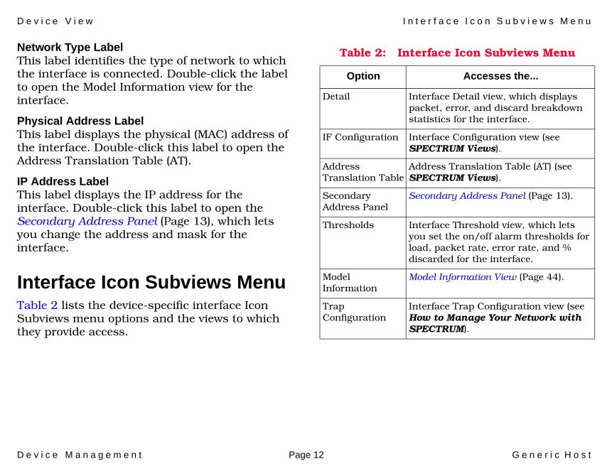
Interface Icon Subviews MenuTable 2 lists the device-specific interface Icon Subviews menu options and the views to which they provide access.
Table 2: Interface Icon Subviews Menu
Option Accesses the...
Detail Interface Detail view, which displays packet, error, and discard breakdown statistics for the interface.
IF Configuration Interface Configuration view (see SPECTRUM Views).
Address Translation Table
Address Translation Table (AT) (see SPECTRUM Views).
Secondary Address Panel
Secondary Address Panel (Page 13).
Thresholds Interface Threshold view, which lets you set the on/off alarm thresholds for load, packet rate, error rate, and % discarded for the interface.
Model Information
Model Information View (Page 44).
Trap Configuration
Interface Trap Configuration view (see How to Manage Your Network with SPECTRUM).

D e v i c e V i e w S e c o n d a r y A d d r e s s P a n e l
D e v i c e M a n a g e m e n t Page 13 G e n e r i c H o s t
Secondary Address PanelAccess: From the Icon Subviews menu for the Interface icon in the Device view, select Secondary Address Panel.
This panel provides a table of IP addresses and masks obtained from the Address Translation table within the device’s firmware. You can change the current address displayed in the IP Address field by selecting an entry from the table in this panel and clicking the Update button.

D e v i c e M a n a g e m e n t Page 14 G e n e r i c H o s t
Device Topology View
This section describes the Device Topology view available for models of the devices.
Access: From the Icon Subviews menu for the Device icon, select DevTop.
The Device Topology view (Figure 4) shows the connections between a modeled device and other network entities. The lower panel of the view uses Interface icons to represent the device’s serial, network, and I/O ports. These icons provide the same information and menu options as those in the Device View (Page 10). If a device is connected to a particular interface, a Device icon appears on the vertical bar above the Interface icon along with an icon representing the network group that contains the device.
Refer to the SPECTRUM Views documentation for details on Device Topology view.
Figure 4: Device Topology View
File View HelpTools
1Ethernet
0:0:1D:F:FD:B6ei0
0.0.0.0
ON 2ATM
0:0:1D:F:FD:B6A2
0.0.0.0
ON 3ATM
0:0:1D:F:FD:B6CPU
0.0.0.0
ON
Bookmarks
SpectroGRAPH: Device Topology: Model Name
Graphic ofGeneric Host
Device
Model Name of type Model Type of Landscape node: Primary

D e v i c e M a n a g e m e n t Page 15 G e n e r i c H o s t
Application Views
This section describes the main Application view and the associated application-specific subviews available for models of the devices in SPECTRUM.
Access: From the Icon Subviews menu for the Device icon, select Application.
Main Application ViewWhen a device model is created, SPECTRUM automatically creates models for each of the major and minor applications supported by the device. The main Application view identifies all of these application models, shows their current condition status, and provides access to application-specific subviews. Figure 5 shows this view in the Icon mode. If you prefer the List mode, which displays applications as text labels, select View > Mode > List.
For more information on this view, refer to the MIBs and the Application View documentation.
Figure 5: Main Application View
SpectroGRAPH: Application: Model Name
Model Name
Contact
Description
Location
Network Address System Up Time
Manufacturer
Device Type
Serial Number
Model Name
6E132_25
Model Name
Model Type
File View Tools Bookmarks
Model Name of type <model type> of Landscape node: Primary
Help

A p p l i c a t i o n V i e w s S u p p o r t e d A p p l i c a t i o n s
D e v i c e M a n a g e m e n t Page 16 G e n e r i c H o s t
Supported ApplicationsSPECTRUM’s applications can be grouped within two general categories as follows:
• Applications associated with non proprietary MIBs. See Common Applications below.
• Applications associated with device-specific MIBs. See Device-Specific MIBs (Page 17).
Common ApplicationsFor the most part, these applications represent the non proprietary MIBs supported by devices. Listed below (beneath the title of the SPECTRUM document that describes them) are some of the common applications currently supported by SPECTRUM. Refer to these documents when your devices support these applications.
• Routing Applications- Generic Routing- Repeater- AppleTalk- DECnet
- OSPF- OSPF2- BGP4- VRRP- RFC 2932
• Bridging Applications- Ethernet Special Database- Spanning Tree- Static- Transparent- PPP Bridging- Source Routing- Translation- QBridge
• MIB II Applications- SNMP- IP- ICMP- TCP- System2- UDP
• Transmission Applications- FDDI- Point to Point- DS1- DS3
Note:Note:
The documents listed below (in bold font) are available for viewing at:
www.aprisma.com/manuals/

A p p l i c a t i o n V i e w s S u p p o r t e d A p p l i c a t i o n s
D e v i c e M a n a g e m e n t Page 17 G e n e r i c H o s t
- RS-232- WAN- Frame Relay- Token Ring- Ethernet- Fast Ethernet- RFC 1317App- RFC 1285App- RFC 1315App- 802.11App- SONET
• Technology Applications- APPN- ATM Client- DHCP- DLSw- PNNI- RFC 1316App- RFC 1514- RFC 2287- RFC 2790- RFC 2925
• DOCSIS Applications- DOCSISCblDvApp - DOCSISQOSApp- DOCSISBPI2App - DOCSISBPIApp
- DOCSISIFApp
• Digital Subscriber Line (DSL) Applications- ADSL
Device-Specific MIBsSPECTRUM imports the following device-level proprietary MIBs into its database:
• LanManager_Mib• Dhcp_Mib• Wins_Mib• Acs_Mib• Ftp_Mib• Http_Mib• RipSap_Mib
These MIBs can be used in conjunction with SPECTRUM’s optional customization products (referred to as the Level I Tool Kits) to create application models and views that display the condition of selected MIB objects.
Note:Note:
Aprisma Management Technologies can provide training, technical assistance, and custom engineering support services for creating application models and their associated views.
A p p l i c a t i o n V i e w s L A N M a n a g e r A p p l i c a t i o n
D e v i c e M a n a g e m e n t Page 18 G e n e r i c H o s t
The following device-specific applications are described in the remainder of this section:
• LAN Manager Application (Page 18) (LanManager_App)
• DHCP Application (Page 21) (dhcpApp)• Wins Application (Page 22) (Wins_App)• Acs Application (Page 27) (Acs_App)• Ftp Application (Page 32) (Ftp_App)• Http Application (Page 33) (Http_App)• RipSap Application (Page 38) (RipSap_App)
LAN Manager ApplicationThis section describes the LAN Manager (LanManager_App) application, which lets you access detailed views of network information related to the Host_Device model type.
This application is based on Microsoft’s NT LAN Manager application and includes the following views and tables:
• System Configuration View (Page 18)• Lan Manager Domains View (Page 18)• Server View (Page 19)• Workstation View (Page 20)• Model Information View (Page 44)
System Configuration ViewAccess: From the Icon Subviews menu for the LanManager_App Application icon, select Configuration.
VersionThe major and minor release version numbers of the LAN Manager software, e.g. 4 0.
Stat StartThe time in seconds since the LAN Manager statistics were last cleared on this node.
Num Net IOsThe number of network I/O operations sent from this node.
Fi Net IOsThe number of network I/O operations on this node that failed to be issued.
Fc Net IOsThe number of network I/O operations on this node that failed to be completed.
Lan Manager Domains ViewAccess: From the Icon Subviews menu for the LanManager_App Application icon, select Domain.
Displays statistics on your domain, other devices in your domain, and other workgroup domains.

A p p l i c a t i o n V i e w s L A N M a n a g e r A p p l i c a t i o n
D e v i c e M a n a g e m e n t Page 19 G e n e r i c H o s t
Primary DomainDisplays information on your workstation domain.
# Other DomainsDisplays information on other workgroup domains.
Server NumberLists server numbers of your domain and servers in other workgroup domains.
Server ViewAccess: From the Icon Subviews menu LanManager_App Application icon, select Server.
This view provides the following statistics on users, print jobs, and network activity on this workstation.
Queued JobsThe number of processes waiting to run.
Sys ErrorsDisplays the number of errors that have occurred.
Avg ResponseThe average response time the server takes to respond to a request.
# UsersThe number of users who are currently using the server.
bytes SentThe number of bytes sent back to those who are using the server.
Rcvd bytesThe number of bytes received in requests.
SecurityA notification of whether a user is the only user or a group who share the resources.
# ServicesThe number of services running on the device at any time. The table gives you the names of the users and the state of the server. Double-click the Name or State column to find out more about the state of any service.
This button accesses the Print Queue view. This view provides the number of print queues, name, and number of jobs.
Print Queue

A p p l i c a t i o n V i e w s L A N M a n a g e r A p p l i c a t i o n
D e v i c e M a n a g e m e n t Page 20 G e n e r i c H o s t
This button accesses the Session Table View. This view provides the client name, time, idle, type, and state.
This button accesses the Shared Table View. This view provides the number of users sharing the machine, along with their names, paths, and comments.
This button accesses the Users View. This view provides the number of users and the name of each user on the machine.
Workstation ViewAccess: From the Icon Subviews menu for the LanManager_App Application icon, select Work Station.
This view provides the following information specific to the workstation.
Session StartsThe number of valid user sessions since the operating system was installed.
Session FailsThe number of times a user tried, but failed, to start a valid session since the operating system was installed.
UsesThe number of times a user has succeeded in using some other machine’s resources.
Use FailsThe number of times the user tried, but failed, to use some other machine’s resources.
Auto RecsInformation is unavailable.
Error Log SizeThe size of the error log, which is set at 16 kilobytes.
Sessions
Share
Users

A p p l i c a t i o n V i e w s D H C P A p p l i c a t i o n
D e v i c e M a n a g e m e n t Page 21 G e n e r i c H o s t
Use NumberThe number of users sharing the machine’s resources.
Local NameThe name of a local device assigned to a remote resource.
RemoteThe name of a remote shared resource to which a local device is assigned.
StatusThe status of the current connection.
DHCP ApplicationThis section describes the DHCP (dhcpApp) application, which lets you access detailed views of network information related to the Host_Device model type.
This application includes the following views:
• Parameters-Dhcp App (Page 21)• Scope View (Page 22)• Model Information View (Page 44)
Parameters-Dhcp AppAccess: From the Icon Subivews menu for Dhcp_App Application icon, select Parameters.
Start timeDhcp Server start time.
# Acks RcvdIndicates the number of acks received.
# Nacks RcvdIndicates the number of nacks received.
Total DeclinesIndicates the total number of declines.
# Offers RcvdIndicates the number of offers sent.
# Releases RcvdIndicates the number of releases received.
# Requests RcvdIndicates the number of requests received.
# Discovers RcvdIndicates the number of discovery messages received.

A p p l i c a t i o n V i e w s W i n s A p p l i c a t i o n
D e v i c e M a n a g e m e n t Page 22 G e n e r i c H o s t
Scope ViewAccess: From the Icon Subviews menu for the Dhcp_App Application icon, select Scope.
SubnetThe subnet address.
Addr In UseThe number of addresses in use.
Free AddrThe number of free addresses.
Pending OffersThe number of addresses that are currently in the offer state.
Wins ApplicationThis section describes the Wins (Wins_App) application, which lets you access detailed views of network information related to the Host_Device model type.
This application includes the following views:
• System Configuration (Page 22)• Notification (Page 23)• Wins Counters (Page 24)• Wins History (Page 24)• Wins Pull (Page 25)
• Wins Settings (Page 26)• Model Information View (Page 44)
System ConfigurationAccess: From the Icon Subviews menu for the Wins_App Application icon, select Configuration.
This view contains the following information.
Push TriggerIP address of the remote WINS to which the WINS will push a notification message when this field is set.
Delete WinsIP Address of the remote WINS for which, when set, WINS information (data records, context information) will be deleted from the local WINS. Use this only when the owner-address mapping table is nearing capacity. Deletion of all information pertaining to the managed WINS is not permitted.
Delete DB RecsIP address which, when set, will cause all data records pertaining to a WINS to be deleted from the local WINS. Only data records are deleted.
Static Init WithSets the name of the file WINS will use to do static initialization. If 0 is specified, WINS will do static

A p p l i c a t i o n V i e w s W i n s A p p l i c a t i o n
D e v i c e M a n a g e m e n t Page 23 G e n e r i c H o s t
initialization using the files specified in the registry. This can be read-written using the Datafile table.
This button allows you to set scavenging to on.
This button allows you to reset the counters.
This button allows you to set the priority class of the WINS to normal or high.
Worker ThreadsSets the number of worker threads in WINS.
This button displays the Data Records view. This view contains the following information:
Populate TableIP Address of the WINS from which you wish to retrieve records. When set, the table is populated instantly.
NameName of the record.
AddressAddress(es) of the record. If the record is a multihomed record or a special group, the addresses are returned sequentially in pairs. Each pair includes the address of the owner WINS followed by the address of the machine (multihomed)/member (special group). Following SNMP’s convention, the records are always returned in network byte order.
TypeType of the record (unique, normal_group, special_group, or multihomed).
PersistencePersistence type of the record.
StateState of the record (active, released, tombstone, or deleted).
NotificationAccess: From the Icon Subviews menu for the Wins_App Application icon, select Notification.
This view contains the following information.
Init TimeIndicates whether a push (i.e. notification message) should be done at invocation.
Do Scavenging
Reset Counters
Priority Class
Data Records
A p p l i c a t i o n V i e w s W i n s A p p l i c a t i o n
D e v i c e M a n a g e m e n t Page 24 G e n e r i c H o s t
On Addr Change NtfyIndicates whether a notification message should be sent when the address changes.
AddressAddress of the WINS partner.
UpdatesNumber of updates that should result in a push message.
Wins CountersAccess: From the Icon Subviews menu for the Wins_App Application icon, select Wins Counters.
This view contains the following information.
Registrations RcvdIndicates the number of registrations received.
Releases RcvdIndicates the number of releases received.
Success ReleasesIndicates the number of releases that have succeeded.
Failed ReleasesIndicates the number of releases that have failed.
Queries RcvdIndicates the number of queries received.
Success QueriesIndicates the number of queries that have succeeded.
Failed QueriesIndicates the number of queries that have failed.
Wins HistoryAccess: From the Icon Subviews menu Wins_App Application icon, select Wins History.
This view contains the following information.
Wins Start TimeWINS start time.
Last Planned ScavengeMost recent date and time at which planned scavenging took place. Planned scavenging happens at intervals specified in the registry. Scavenging involves changing owned, non-refreshed entries to the released state. As a result of scavenging, replicas may be changed to tombstones, tombstones may be deleted and revalidation of old replicas may take place.
Last Admin ScavengeMost recent date and time at which scavenging as a result of administrative action took place.

A p p l i c a t i o n V i e w s W i n s A p p l i c a t i o n
D e v i c e M a n a g e m e n t Page 25 G e n e r i c H o s t
Last Tombstone ScavengeMost recent date and time at which replica tombstone scavenging took place.
Last RevalidationMost recent date and time at which revalidation of old active replicas took place.
Last Planned ReplicationMost recent date and time at which planned replication took place. Planned replication happens at intervals specified in the registry.
Last Admin ReplicationMost recent date and time at which administrator-triggered replication took place.
Last Network ReplicationMost recent date and time at which network triggered replication took place. Network triggered replication happens as a result of an update notification message from a remote WINS.
Last Addr Chng ReplicationMost recent date and time at which address change-triggered replication took place. Address change-triggered replication happens when the address of an owned name changes due to a new registration.
Last Database InitializedMost recent date and time at which the local database was populated statically from one or more data files.
Last Local Counters ResetMost recent date and time at which the local counters were initialized to zero.
Wins PullAccess: From the Icon Subviews menu for the Wins_App Application icon, select Wins Pull.
This view contains the following information.
Init TimeIndicates whether pull should be done at WINS invocation and at reconfiguration. Setting any of the Wins Pull fields constitutes reconfiguration.
Retry CountDisplays the retry count in case of comm. failure when doing pull replication. This is the maximum number of retries that will be done at the interval specified for the partner before WINS will stop for a certain number (canned) of replication time intervals before starting again.
Partner A list of partners with which pull replication needs to be done.

A p p l i c a t i o n V i e w s W i n s A p p l i c a t i o n
D e v i c e M a n a g e m e n t Page 26 G e n e r i c H o s t
When PullTime at which pull replication should occur.
IntervalTime interval for pull replication.
PrecedenceThis is the precedence to be given to members of the special group pulled from the WINS. The precedence of locally registered members of a special group is higher than any replicas pulled in. Possible values are low (0) and high (1).
Reps SuccessThe number of times replication with the WINS was successful after invocation or reset of counters.
Reps FailThe number of times replication with the WINS was unsuccessful due to comm. failure after invocation or reset of counters.
Wins SettingsAccess: From the Icon Subviews menu for the Wins_App Application icon, select Wins Settings.
This view contains the following information.
Refresh Interval (1/1000 sec)Indicates the refresh interval (in milliseconds).
Tombstone Interval (1/1000 sec)Indicates the tombstone interval (in milliseconds).
Tombstone Timeout (1/1000 sec)Indicates the tombstone timeout (in milliseconds).
Verify Interval (1/1000 sec)Indicates the verify interval (in milliseconds).
Replication w/wo PartnersIndicates whether or not replication should be done with non-configured partners. Unless this field is set to zero, replication will be done only with partners listed in the registry (except when an update notification comes in).
Static Data InitIndicates whether static data should be read in at initialization and reconfiguration time. Setting any of the Wins Settings fields constitutes reconfiguration.
Logging EnabledIndicates whether logging should be done. Default behavior is to do logging.
Log File NameSpecifies the path to the log file.
Backup PathSpecifies the path to the backup directory.

A p p l i c a t i o n V i e w s A c s A p p l i c a t i o n
D e v i c e M a n a g e m e n t Page 27 G e n e r i c H o s t
This button specifies whether WINS should do backup on termination. The backup path must also be specified in addition to setting this field to yes.
This button specifies whether static records in the wins database should be treated as dynamic records during conflicts with new dynamic registrations.
Acs ApplicationThis section describes the Acs Application (Acs_App) application, which lets you access detailed views of information related to managing host systems using the Host_Device model type.
The following views are available:
• ACS Server Statistics (Page 27)• ACS If Statistics View (Page 28)• MSIDLPM View (Page 30)• Model Information View (Page 44)
ACS Server StatisticsAccess: From the Icon Subviews menu for the Acs_App Application icon, select Statistics.
InterfacesThe number of network interfaces on this system detected by ACS server.
NotificationsThe total number of notifications sent by this ACS Server to QoS aware applications.
Notification bytesThe total number of bytes in notifications sent by this ACS Server to QoS aware applications.
Active API SocketsThe total number of API sockets active on this ACS Server.
Active API SessionsThe total number of API sessions active on this ACS Server.
TimersThe total number of timer events currently active in this ACS Server.
Failed API SendsThe total number of requests which could not be sent to QoS aware applications by this ACS Server.
Backup on Termination
Migrate On

A p p l i c a t i o n V i e w s A c s A p p l i c a t i o n
D e v i c e M a n a g e m e n t Page 28 G e n e r i c H o s t
Failed Api RequestsThe total number of requests received from QoS aware applications by this ACS Server which failed.
Received Resv ReqsThe total number of Resv requests received from QoS aware applications by this ACS Server.
Received Path ReqsThe total number of Path requests received from QoS aware applications by this ACS Server.
Net SocketsThe total number of network sockets currently opened by this ACS Server.
ACS If Statistics ViewAccess: From the Icon Subviews menu for the Acs_App Application icon, select If Statistics.
acsIfStatsIndexA unique value for each interface. Its value ranges between 1 and the value of ifNumber. The value for each interface must remain constant at least from one re-initialization of the entity's network management system to the next re-initialization.
acsIfStatsIpAddrThe IP address of the interface to which these statistics pertain.
acsIfStatsRawIpSentbytesThe total number of Raw IP bytes sent by this ACS Server.
acsIfStatsRawIpReceivedbytesThe total number of Raw IP bytes received by this ACS Server.
acsIfStatsReceivedRsvpPathMsgsThe total number of RSVP Path messages received by this ACS Server.
acsIfStatsReceivedRsvpResvMsgsThe total number of RSVP Resv messages received by this ACS Server.
acsIfStatsReceivedRsvpPathErrMThe total number of RSVP PathErr messages received by this ACS Server.
acsIfStatsReceivedRsvpResvErrMThe total number of RSVP ResvErr messages received by this ACS Server.
acsIfStatsReceivedRsvpPathTearThe total number of RSVP PathTear messages received by this ACS Server.
acsIfStatsReceivedRsvpResvTearThe total number of RSVP ResvTear messages received by this ACS Server.

A p p l i c a t i o n V i e w s A c s A p p l i c a t i o n
D e v i c e M a n a g e m e n t Page 29 G e n e r i c H o s t
acsIfStatsReceivedRsvpConfirmMThe total number of RSVP Confirm messages received by this ACS Server.
acsIfStatsSentRsvpPathMsgsThe total number of RSVP Path messages sent by this ACS Server.
acsIfStatsSentRsvpResvMsgsThe total number of RSVP Resv messages sent by this ACS Server.
acsIfStatsSentRsvpPathErrMsgsThe total number of RSVP PathErr messages sent by this ACS Server.
acsIfStatsSentRsvpResvErrMsgsThe total number of RSVP ResvErr messages sent by this ACS Server.
acsIfStatsSentRsvpPathTearMsgsThe total number of RSVP PathTear messages sent by this ACS Server.
acsIfStatsSentRsvpResvTearMsgsThe total number of RSVP ResvTear messages sent by this ACS Server.
acsIfStatsSentRsvpConfirmMsgsThe total number of RSVP Confirm messages sent by this ACS Server.
acsIfStatsAdmissionControlFailThe total number of Admission Control errors generated by this ACS Server.
acsIfStatsPolicyControlFailureThe total number of Policy Control errors generated by this ACS Server.
acsIfStatsOtherFailuresThe total number of Other type errors generated by this ACS Server.
acsIfStatsInBlockadeStateResvsThe total number of Resv State Blocks in blockade state in this ACS Server.
acsIfStatsResvTimeOutsThe total number of Reservations which have timed out in this ACS Server.
acsIfStatsPathTimeOutsThe total number of Path states which have timed out in this ACS Server.
acsIfStatsReceiveFailsBigMsgThe total number of RSVP messages which could not be received by this ACS Server because they are too big to fit in the message buffer.
acsIfStatsSendFailsBigMsgThe total number of RSVP messages which could not be sent by this ACS Server because they are too big to fit in the message buffer.

A p p l i c a t i o n V i e w s A c s A p p l i c a t i o n
D e v i c e M a n a g e m e n t Page 30 G e n e r i c H o s t
acsIfStatsReceiveFailsNoMemoryThe total number of RSVP messages which could not be sent by this ACS Server because there was no free message buffer.
acsIfStatsSendFailsNoMemoryThe total number of RSVP messages which could not be sent by this ACS Server because there was no free message buffer.
acsIfStatsActiveFlowsThe total number flows currently active in this ACS Server.
acsIfStatsAllocatedBandwidthBiThe total bandwidth currently allocated by this ACS Server.
acsIfStatsMaxAllocatedBandwidtThe maximum bandwidth ever allocated by this ACS Server.
MSIDLPM ViewAccess: From the Icon Subviews menu for the Acs_App Application icon, select MSIDLPM.
acsMsidlpmStatsIndexA unique value for each subnet. Its value ranges between 1 and the value of ifNumber. The value for each subnet must remain constant at least
from one re-initialization of the entity's network management system to the next re-initialization.
acsMsidlpmStatsSubnetAddrThe IP address of the subnet to which these statistics pertain.
acsMsidlpmSenderAcceptedThe total number of senders whose PATH messages were accepted.
acsMsidlpmSenderChgAcceptedThe total number of senders whose PATH message changes were accepted.
acsMsidlpmRejSndFlowRateThe total number of senders whose PATH message were rejected because of data flow rate policy.
acsMsidlpmRejSndPeakRateThe total number of senders whose PATH message were rejected because of peak data rate policy.
acsMsidlpmRejSndSumFlowRateThe total number of senders whose PATH message were rejected because of aggregate data flow rate policy.
A p p l i c a t i o n V i e w s A c s A p p l i c a t i o n
D e v i c e M a n a g e m e n t Page 31 G e n e r i c H o s t
acsMsidlpmRejSndSumPeakRateThe total number of senders whose PATH message were rejected because of aggregate peak data rate policy.
acsMsidlpmRejSndIdChangeThe total number of senders whose PATH message were rejected because of identity change.
acsMsidlpmRejSndDurationThe total number of senders whose PATH message were rejected because of flow duration policy.
acsMsidlpmRejSndCountThe total number of senders whose PATH message were rejected because of flow count policy.
acsMsidlpmRejSndOthersPoliciesThe total number of senders whose PATH message were rejected because of policies other than flow rate, peak rate, flow duration and flow count.
acsMsidlpmReceiversAcceptedThe total number of receivers whose RESV messages were accepted.
acsMsidlpmReceiverChgAcceptedThe total number of receivers whose RESV message changes were accepted.
acsMsidlpmRejRecvFlowRateThe total number of receivers whose RESV message were rejected because of data flow rate policy.
acsMsidlpmRejRecvPeakRateThe total number of receivers whose RESV message were rejected because of peak data rate policy.
acsMsidlpmRejRecvSumFlowRateThe total number of receivers whose RESV message were rejected because of aggregate data flow rate policy.
acsMsidlpmRejRecvSumPeakRateThe total number of receivers whose RESV message were rejected because of aggregate peak data rate policy.
acsMsidlpmRejRecvIdChangeThe total number of senders whose RESV message were rejected because of identity change.
acsMsidlpmRejRecvDurationThe total number of receivers whose RESV message were rejected because of flow duration policy.
A p p l i c a t i o n V i e w s F t p A p p l i c a t i o n
D e v i c e M a n a g e m e n t Page 32 G e n e r i c H o s t
acsMsidlpmRejRecvCountThe total number of receivers whose RESV message were rejected because of flow count policy.
acsMsidlpmRejRecvOthersPolicieThe total number of receivers whose RESV message were rejected because of policies other than flow rate, peak rate, flow duration and flow count.
acsMsidlpmBadIdentityPesThe total number of Identity Policy elements which could not be cracked by the MSIDLPM.
acsMsidlpmDsCacheSizeThe total number of entries in the policy cache maintained by the MSIDLPM.
Ftp ApplicationThis section describes the Ftp Application (Ftp_App) application, which lets you access detailed views of information related to managing host systems using the Host_Device model type.
The following views are available:
• FTP Statistics (Page 32)• Model Information View (Page 44)
FTP StatisticsAccess: From the Icon Subviews menu for the Ftp_App Application icon, select Statistics.
User Information
Current Non Anonymous UsersThe number of non anonymous users currently connected to the FTP Server.
Total Non Anonymous UsersThe total number of non anonymous users that have ever connected to the FTP Server.
Max Non Anonymous UsersThe maximum number of non anonymous users simultaneously connected to the FTP Server.
Current Anonymous UsersThe number of anonymous users currently connected to the FTP Server.
Total Anonymous UsersThe total number of anonymous users that have ever connected to the FTP Server.
Max Anonymous UsersThe maximum number of anonymous users simultaneously connected to the FTP Server.

A p p l i c a t i o n V i e w s H t t p A p p l i c a t i o n
D e v i c e M a n a g e m e n t Page 33 G e n e r i c H o s t
Traffic Information
Total bytes Sent High WordThe high 32-bits of the total number of bytes sent by the FTP Server.
Total bytes Received High WordThe high 32-bits of the total number of bytes received by the FTP Server.
Total Files ReceivedThe total number of files received by this FTP Server.
Total bytes Sent Low WordThe low 32-bits of the total number of bytes sent by the FTP Server.
Total bytes Received Low WordThe low 32-bits of the total number of bytes received by the FTP Server.
Total Files SentThe total number of files sent by this FTP Server.
Connection Information
Current ConnectionsThe current number of connections to the FTP Server.
Connection AttemptsThe number of connection attempts that have been made to the FTP Server.
Max ConnectionsThe maximum number of simultaneous connections to the FTP Server.
Logon AttemptsThe number of logon attempts that have been made to the FTP Server.
Http ApplicationThis section describes the Http application (Http_App), which lets you access detailed views of information related to managing host systems using the Host_Device model type.
The following views are available:
• HTTP Statistics (Page 34)• HTTP Requests (Page 35)• HTTP Method Requests (Page 36)• HTTP BGI/CGI Requests (Page 37)• Model Information View (Page 44)

A p p l i c a t i o n V i e w s H t t p A p p l i c a t i o n
D e v i c e M a n a g e m e n t Page 34 G e n e r i c H o s t
HTTP StatisticsAccess: From the Icon Subviews menu for the Http_App Application icon, select Statistics.
User Information
Current Non Anonymous UsersThe number of non anonymous users currently connected to the HTTP Server.
Total Non Anonymous UsersThe total number of non anonymous users that have ever connected to the HTTP Server.
Max Non Anonymous UsersThe maximum number of non anonymous users simultaneously connected to the HTTP Server.
Current Anonymous UsersThe number of anonymous users currently connected to the HTTP Server.
Total Anonymous UsersThe total number of anonymous users that have ever connected to the HTTP Server.
Max Anonymous UsersThe maximum number of anonymous users simultaneously connected to the HTTP Server.
Traffic Information
Total bytes Sent High WordThe high 32-bits of the total number of bytes sent by the HTTP Server.
Total bytes Received High WordThe high 32-bits of the total number of bytes received by the HTTP Server.
Total Files ReceivedThe total number of files received by this HTTP Server.
Total bytes Sent Low WordThe low 32-bits of the total number of bytes sent by the HTTP Server.
Total bytes Received Low WordThe low 32-bits of the total number of bytes received by the HTTP Server.
Total Files SentThe total number of files sent by this HTTP Server.
Connection Information
Current ConnectionsThe current number of connections to the HTTP Server.

A p p l i c a t i o n V i e w s H t t p A p p l i c a t i o n
D e v i c e M a n a g e m e n t Page 35 G e n e r i c H o s t
Connection AttemptsThe number of connection attempts that have been made to the HTTP Server.
Max ConnectionsThe maximum number of simultaneous connections to the HTTP Server.
Logon AttemptsThe number of logon attempts that have been made to the HTTP Server.
HTTP RequestsAccess: From the Icon Subviews menu for the Http_App Application icon, select General.
General Request Information
Current Blocked RequestsThe current number of requests that have been temporarily blocked by this HTTP Server due to bandwidth throttling settings.
Total Allowed RequestsThe total number of requests that have been allowed by the bandwidth throttling settings on this HTTP Server.
Total ‘locked’ ErrorsThe total number of requests the HTTP Server could not satisfy because the requested resource was locked.
Measured BandwidthThe I/O bandwidth used by this HTTP Server, averaged over a minute.
Total Blocked RequestsThe total number of requests that have been temporarily blocked by this HTTP Server due to bandwidth throttling settings.
Total Rejected RequestsThe total number of requests that have been rejected by this HTTP Server due to bandwidth throttling settings.
Total ‘Not Found’ ErrorsThe total number of requests the HTTP server could not satisfy because the requested resource could not be found.
Client Access Licenses
Current for Authenticated UsersThe current count of Client Access Licenses (CALs) available to this HTTP Server for simultaneous use by authenticated users.

A p p l i c a t i o n V i e w s H t t p A p p l i c a t i o n
D e v i c e M a n a g e m e n t Page 36 G e n e r i c H o s t
Total Failed Authenticated UsersThe total number of HTTP requests that have failed on this HTTP Server due to a Client Access License (CAL) being unavailable for an authenticated user.
Max for Authenticated UsersThe maximum count of Client Access Licenses (CALs) used by this HTTP Server for simultaneous use by authenticated users.
Current for Secure ConnectionThe current count of Client Access Licenses (CALs) available to this HTTP Server for simultaneous use by secure connections.
Total Failed Secure ConnectionThe total number of HTTP requests that have failed on this HTTP Server due to a Client Access License (CAL) being unavailable for use by a secure connection.
Max for Secure ConnectionThe maximum count of Client Access Licenses (CALs) available to this Http Server for simultaneous use by secure connections.
HTTP Method RequestsAccess: From the Icon Subviews menu for the Http_App Application icon, select Method.
PROPPATCHThe number of requests using the PROPPATCH method that have been made to this HTTP Server.
TRACEThe number of requests using the TRACE method that have been made to this HTTP Server.
LOCKThis is the number of requests using the LOCK method that have been made to this HTTP Server.
UNLOCKThe number of requests using the UNLOCK method that have been made to this HTTP Server.
POSTThe number of requests using the POST method that have been made to this HTTP Server.
PROPFINDThe number of requests using the PROPFIND method that have been made to this HTTP Server.
GETThe number of requests using the GET method that have been made to this HTTP Server.
A p p l i c a t i o n V i e w s H t t p A p p l i c a t i o n
D e v i c e M a n a g e m e n t Page 37 G e n e r i c H o s t
MKCOLThe number of requests using the MKCOL method that have been made to this HTTP Server.
HEADThe number of requests using the HEAD method that have been made to this HTTP Server.
MOVEThe number of requests using the MOVE method that have been made to this HTTP Server.
DELETEThe number of requests using the DELETE method that have been made to this HTTP Server.
OPTIONSThe number of requests using the OPTIONS method that have been made to this HTTP Server.
PUTThe number of requests using the PUT method that have been made to this HTTP Server.
COPYThe number of requests using the COPY method that have been made to this HTTP Server.
MS-SEARCHThe number of requests using the MS-SEARCH method that have been made to this HTTP Server.
OTHERThe number of requests not using the OPTIONS, GET, HEAD POST, PUT, DELETE, TRACE, MOVE, COPY, MKCOL, PROPFIND, PROPPATCH, MS-SEARCH, LOCK or UNLOCK method that have been made to this HTTP Server. This may include LINK or other methods supported by gateway applications.
HTTP BGI/CGI RequestsAccess: From the Icon Subviews menu for the Http_App Application icon, select BGI/CGI.
Total BGI ReqsThe number of Binary Gateway Interface (BGI) requests that have been made to this HTTP Server.
Current BGI ReqsThe number of Binary Gateway Interface (BGI) requests that are currently being serviced by this HTTP Server.
Max BGI ReqsThe maximum number of Binary Gateway Interface (BGI) requests simultaneous processed by this HTTP Server.
A p p l i c a t i o n V i e w s R i p S a p A p p l i c a t i o n
D e v i c e M a n a g e m e n t Page 38 G e n e r i c H o s t
Total CGI ReqsThe number of Common Gateway Interface (CGI) requests that have been made to this HTTP Server.
Current CGI ReqsThe number of CGI (CGI) requests that are currently being serviced by this HTTP Server.
Max CGI ReqsThe maximum number of CGI (CGI) requests simultaneous processed by this HTTP Server.
RipSap ApplicationThis section describes the RipSap (RipSap_App) application, which lets you access detailed views of information related to managing host systems using the Host_Device model type.
The following views are available:
• RIP View (Page 38)• SAP View (Page 39)• Model Information View (Page 44)
RIP ViewAccess: From the Icon Subviews menu for the RipSap_App Application icon, select RIP.
IndexThe identifier of this interface, unique within the instance of RIP.
Oper StateThe current operational state of the interface. If Admin State is disabled then the Oper State should be down. If Admin State is changed to enabled then Oper State should change to up. If the interface is ready to transmit and receive network traffic; it should change to sleeping. If the interface is waiting for external actions (such as a serial line waiting for an incoming connection); it should remain in the down state only if there is a fault that prevents it from going to the up state.
Admin StateThe desired state of the interface.
Update ModeThe RIP update mechanism used on this interface. None is used for static routes configurations. AutoStatic means that the local router can issue an update request to the remote router and the response will be kept statically in the routing database as auto static routes.

A p p l i c a t i o n V i e w s R i p S a p A p p l i c a t i o n
D e v i c e M a n a g e m e n t Page 39 G e n e r i c H o s t
Standard is the periodic broadcast RIP mechanism.
Update IntervalThe RIP update interval, in sec. For Standard Update Mode, this is the interval with which periodic update broadcasts are sent, for AutoStatic Update Mode, this is the maximum interval for which router will listen for RIP announcements, not used for None Update Mode.
Out PacketsThe number of RIP packets sent on this interface.
In PacketsThe number of RIP packets received on this interface.
ListenEnable listening to RIP updates on this interface.
SupplyEnable sending of RIP updates (change and periodic) on this interface.
Age MultThe holding multiplier for routes received in RIP periodic updates (applies only if Update Mode is Standard).
SAP ViewAccess: From the Icon Subviews menu for the RipSap_App Application icon, select SAP.
IndexThe identifier of this interface, unique within the instance of SAP.
Oper StateThe current operational state of the interface. If Admin State is disabled then the Oper State should be down. If Admin State is changed to enabled then Oper State should change to up. If the interface is ready to transmit and receive network traffic; it should change to sleeping. If the interface is waiting for external actions (such as a serial line waiting for an incoming connection); it should remain in the down state only if there is a fault that prevents it from going to the up state.
Admin StateThe desired state of the interface.
Update ModeThe SAP update mechanism used on this interface. None is used for static routes configurations. AutoStatic means that the local router can issue an update request to the remote router and the response will be kept statically in the routing database as auto static routes.

A p p l i c a t i o n V i e w s R i p S a p A p p l i c a t i o n
D e v i c e M a n a g e m e n t Page 40 G e n e r i c H o s t
Standard is the periodic broadcast SAP mechanism.
Update IntervalThe SAP update interval, in sec. For Standard Update Mode, this is the interval with which periodic update broadcasts are sent, for AutoStatic Update Mode, this is the maximum interval for which router will listen for SAP announcements, not used for None Update Mode.
Out PacketsThe number of SAP packets sent on this interface.
In PacketsThe number of SAP packets received on this interface.
ListenEnable listening to SAP updates on this interface.
SupplyEnable sending of SAP updates (change and periodic) on this interface.
Age MultThe holding multiplier for routes received in SAP periodic updates (applies only if Update Mode is Standard).
Nearest Server RepIndicates whether to respond to SAP get nearest server requests received on this interface.

D e v i c e M a n a g e m e n t Page 41 G e n e r i c H o s t
Performance Views
This section introduces the Performance view. For details concerning this view, refer to the SPECTRUM Views documentation.
Performance views display performance statistics in terms of a set of transmission attributes, e.g., cell rates, frame rates, % error, etc. A typical view is shown in Figure 6. The instantaneous condition of each transmission attribute is recorded in a graph. The statistical information for each attribute is presented in the adjacent table.
Generally, you determine performance at the device level through Performance views accessed from the Device and Application icons. You determine performance at the port/interface level through Performance views accessed from Interface icons.
Figure 6: Performance View
SpectroGRAPH: Type Routing
File View Tools Bookmarks
% Discarded
type routing of type IP Routing of Landscape node: Primary
Performance View
Day/Month/ Time/ Year
100.0
10.01.000.100.010
00:30 00:20 00:10 0
* Frame/Sec
% Received
% Forwarded
% Trans
Value Average Peak Value
Scroll to Date-TimeGraph Properties* Graph X 1000
Log
Network Address Device Type
% Error
% Discarded
Detail
D e v i c e M a n a g e m e n t Page 42 G e n e r i c H o s t
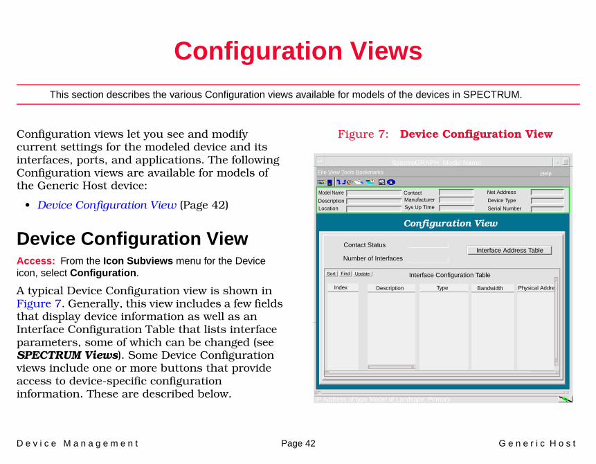
Configuration Views
This section describes the various Configuration views available for models of the devices in SPECTRUM.
Configuration views let you see and modify current settings for the modeled device and its interfaces, ports, and applications. The following Configuration views are available for models of the Generic Host device:
• Device Configuration View (Page 42)
Device Configuration ViewAccess: From the Icon Subviews menu for the Device icon, select Configuration.
A typical Device Configuration view is shown in Figure 7. Generally, this view includes a few fields that display device information as well as an Interface Configuration Table that lists interface parameters, some of which can be changed (see SPECTRUM Views). Some Device Configuration views include one or more buttons that provide access to device-specific configuration information. These are described below.
Figure 7: Device Configuration View
SpectroGRAPH: Model Name
Model Name
File View Tools Bookmarks Help
DescriptionLocation
ContactManufacturerSys Up Time
Net Address
Device Type
Serial Number
Configuration View
Contact Status
Number of InterfacesInterface Address Table
Sort Interface Configuration Table
Index Description Type Bandwidth Physical Addre
IP Address of type Model of Landsape: Primary
Find Update
C o n f i g u r a t i o n V i e w s D e v i c e C o n f i g u r a t i o n V i e w
D e v i c e M a n a g e m e n t Page 43 G e n e r i c H o s t
Refer to the SPECTRUM Views documentation.
Interface Address Translation

D e v i c e M a n a g e m e n t Page 44 G e n e r i c H o s t
Model Information View
This section provides a brief overview of the Model Information view.
This view displays administrative information about the device and its applications and lets you set thresholds and alarm severity for the device.
Figure 8 shows a sample Model Information view. The layout of this view is the same for all model types in SPECTRUM but some information will vary depending on the model it defines. Refer to the SPECTRUM Views documentation for a complete description of this view.
Figure 8: Model Information View
Model Name ContactDescriptionLocation
SpectroGRAPH: Model Name
File View Tools Bookmarks Help
IP Address of Model Type of Landscape: Primary
ManufacturerSysUpTime
Net AddressDevice TypeSerial Number
Model Information View
MM Name
MM Part Number
MM Version Number
Model Type
Model Creation Time
Model Created By
Model State
Security String
Communication Information
Poll / Log Information
Condition Value
Contact Status
DCM TimeOut
DCM Retry
Lost Child Count
Value When Yellow
Value When OrangeValue When Red
Community Name
Mgnmt Protocol
Poll Interval
Poll Status
Log Ratio
Last Successful Poll
Logged Polled
True
General InformationCondition

D e v i c e M a n a g e m e n t Page 45 G e n e r i c H o s t
Index
AAcs Application 27
If Statistics View 28MSIDLPM View 30Server Statistics 27
AddressInterface IP 12Physical (MAC) 12Translation 13
Admin Status 11Administrative Status 9Application
Device-Specific Applications 18Applications 15
CConfiguration
Device 42
DDevice
Information 9DevTop Views 14
DHCP Application 21Parameters 21Scope 22
Documentation 5
EEthernet Application 41
FFtp Application 32
Statistics 32
HHttp Application 33
BGI/CGI Requests 37Method Requests 36Requests 35Statistics 34
IIcons
Interface 11Interface
Type, Device 11Interface Device View 10
LLAN Manager Application 18
Lan Manager Domains View 18System Configuration View 18User (Server) Information 19
Print Queue 9, 19Sessions 9, 20Share 9, 20Users 9, 20
Views 18Workstation Information 20
MManagement Tasks 9Mask 13Model

I n d e x I n d e x
D e v i c e M a n a g e m e n t Page 46 G e n e r i c H o s t
Information 44Model Types 6
NNetwork I/O ports 14Network Type 12NT Information 9
PPerformance
(check) 9Device and Port 9
Performance Statistics 41Port Number, Device 11
RRipSap Application 38
RIP View 38SAP View 39
SSerial ports 14SPECTRUM Software Modules 6
TThreshold Information 12Topology
Information 9Trap Configuration 12Troubleshooting Tasks 9
WWins Application 22
Notification 23System Configuration 22
Data Records 9, 23Do Scavenging 9Priority Class 9Reset Counters 9
Wins Counters 24Wins History 24Wins Pull 25Wins Settings 26
Backup on Termination 9Migrate On 9
Workstation Troubleshooting 9


