Programmable DC Power Supplies 10/15kW in 3U Built in RS-232 & RS-485 Interface Parallel Current Summing Optional Interfaces: USB LAN IEEE488.2 SCPI Multi-Drop Isolated Analog Interface Programmable DC Power Supplies 10/15kW in 3U Built in RS-232 & RS-485 Interface Parallel Current Summing Optional Interfaces: USB LAN IEEE488.2 SCPI Multi-Drop Isolated Analog Interface Compliant Compliant Genesys TM Genesys TM Family GEN H 750W Half Rack GEN 1U 750/1500W Full Rack GEN 2U 3.3/5kW GEN 3U 10/15kW www.us.tdk-lambda.com/hp
Transcript
Programmable DC Power Supplies10/15kW in 3U
Built in RS-232 & RS-485 InterfaceParallel Current Summing
Optional Interfaces: USBLAN
IEEE488.2 SCPI Multi-DropIsolated Analog Interface
Programmable DC Power Supplies10/15kW in 3U
Built in RS-232 & RS-485 InterfaceParallel Current Summing
Optional Interfaces: USBLAN
IEEE488.2 SCPI Multi-DropIsolated Analog Interface
CompliantCompliant
GenesysTM
GenesysTM FamilyGEN H 750W Half RackGEN 1U 750/1500W Full RackGEN 2U 3.3/5kWGEN 3U 10/15kW
www.us.tdk-lambda.com/hp
1
ApplicationsGenesys™ power supplies are designed for demanding applications.
Test & Measurement systems using GPIB control save significant costs by incorporating the optionalIEEE Multi-Drop Interface (IEMD) in the Master. Then up to 30 Slaves may be equipped with the less expensiveOptional RS-485 Multi-Drop (MD) interface.
Automated System designers will appreciate new, standard, remote programming features such asGlobal commands. Also, new high-speed status monitoring is available for the RS-485 bus as well as optionalLAN (LXI compliant) or USB Interfaces.
Industrial & Military high power systems can be configured with up to four identical units in parallel, up to 60kW.No space is required above or below each power supply (zero stack). The Master can be configured by the user toreport total current of the combination. Applications include Heaters, Magnets and Laser Diodes.
Aerospace & Satellite Testing systems use the complete Genesys™ Family: 1U 750W Half Rack,1U 750W or 1500W Full-Rack, 2U 3.3kW and 3U 10/15kW. All are identical in Front Panel, Rear Panel Analog andDigital Interface Commands. A wide variety of outputs allows testing of many different devices.
Component Device Testing is simplified because of the many user-friendly control options in analog anddigital interfaces. Lamps, capacitors, motors and actuators are typical devices tested.
Medical Imaging and Treatment systems require reliable power. Modular construction, SMT and thoroughlyproven designs assure continuous performance at full rated power.
Semiconductor Processing & Burn-in equipment designers appreciate the wide variety of worldwide Inputs andOutputs from which to select depending on application. Selectable Safe and Auto Re-start protects loads and processintegrity. Typical applications include Magnets, Filaments and Heaters.
The Genesys™ family of programmable power supplies sets a new standard for flexible, reliable, AC/DC power systems in Test & Measurement, Industrial and OEM applications.
• High Power Density 10/15kW in 3U• High Current up to 1,000ADC• Wide Range of popular worldwide 3φ AC inputs, (208VAC, 400VAC, 480VAC)• Power Factor 0.88 (Passive Correction on all Inputs)• Output Voltage up to 600V, Current up to 1,000A• Built-in RS-232/RS-485 Interface Standard• Last Setting Memory; Front Panel Lockout• Advanced Parallel reports total current up to four identical units• Global Commands for Serial RS-232/RS-485 Interface• Reliable Encoders for Voltage and Current Adjustment• Independent Remote ON/OFF and Remote ENABLE/DISABLE• Reliable Modular and SMT Design• 19" Rack Mounted for ATE and OEM Applications, zero stack• Optional Interfaces Isolated Analog Programming and Monitoring IEEE Multi-Drop - SCPI Compliant LAN Interface USB Interface• Labview™ and LabWindows™ drivers• Five Year Warranty
Worldwide Safety Agency Approvals; UL Recognized and CE Mark for LVDand EMC Regulation (208VAC and 400VAC Input)
Features include:
Genesys 3U 10/15kWTM
2
1. Remote/Local Output Voltage Sense Connections2. DIP Switches select 0-5V or 0-10V Programming and other functions3. DB25 (Female) connector allows (Non-isolated) Analog Program and Monitor and other functions 4. RS-485 OUT to other Genesys™ Power Supplies 5. RS-232/RS-485 IN Remote Serial Programming6. Output Connections: Rugged 2 hole busbars (shown) for up to 80V Output, single hole
7. Exit air assures reliable operation when zero stacked8. Input Terminals L1, L2, L3, Ground, threaded studs.
9. Optional Interfaces Position for IEEE 488.2 (GPIB), Isolated Analog Interface, LAN Interface or USB Interface
Front Panel Description
• Coarse and fine Adjustment of Output Voltage/Current and Advanced Parallel Master or Slave select• Preview settings and set Voltage/Current with Output OFF, Front Panel Lock• Parallel Master/Slave• Set OVP and UVL Limits• Set Current Foldback Protection• Go to Local Mode and select Address and Baudrate • Output ON/OFF and Auto-Re-Start/Safe-Start Mode
8. Pushbuttons allow flexible user configuration
1. ON/OFF Switch2. Air Intake allows zero stacking for maximum system flexibility and power density3. Reliable encoder controls Output Voltage, Address, OVP and UVL settings 4. Volt Display shows Output Voltage and directly displays OVP, UVL and Address settings 5. Reliable encoder controls Output Current, sets Baudrate, and Advanced Parallel Mode6. Current Display shows Output Current and displays Baudrate. Displays total current in Parallel Master/Slave Mode7. Function/Status LEDs:
• Alarm• Foldback Mode
• Fine Control• Remote Mode
• Preview Settings• Output On
3
GEN 7.5-1000 10-1000 12.5-800 20-500 25-400 30-333 40-250 50-200 60-167 10kW 15kW1.Rated output voltage V 7.5 10 12.5 20 25 30 40 50 60 X2.Rated output current A 1000 1000 800 500 400 333 250 200 167 X3.Rated output power kW 7.5 10.0 10.0 10.0 10.0 10.0 10.0 10.0 10.0 X4.Efficiency (min) at low line, 100% Rated Load % 77 X
1.0 MODEL 60-250 15kW1.Rated output voltage V N/A N/A N/A N/A N/A N/A N/A N/A 60 X2.Rated output current A 250 X3.Rated output power kW 15.0 X4.Efficiency (min) at low line, 100% Rated Load % 88 X
1. Max. line regulation (0.1% Vo Max =<30V; 0.01%>30V) mV 7.5 10 12.5 20 25 30 4 5 6 X X2. Max. load regulation (0.1% Vo Max =<30V; 0.02%>30V) mV 7.5 10 12.5 20 25 30 8 10 12 X X3. Ripple r.m.s 5Hz~1MHz c.v (*1) mV 20 20 20 20 20 20 20 20 20 X X4. Output noise p-p(20MHz) c.v (*1) mV 60 60 60 60 60 60 60 75 75 X X5. Remote sense compensation/wire V 1 1 1 1 1 1.5 2 3 3 X X6. Temperature Stability c.v. --- X X7. Temperature Coefficient c.v. PPM/C X X8. Up-prog. response time, 0~Vomax full-load mS 100 100 100 100 100 100 100 100 100 X X9. Up-prog. response time, 0~Vomax, no load mS 50 50 50 50 50 50 50 50 50 X X10. Transient response time (cv mode) (*2) mS X X
1.2 CONSTANT CURRENT MODE1. Max. line regulation (0.1% Io Max =>333A; 0.05%<333A) mA 1000 1000 800 500 400 333 125 100 83.5 X2. Max. load regulation (0.1% Io Max =>333A; 0.075%<333A) mA 1000 1000 800 500 400 333 188 150 125 X1. Max. line regulation (0.1% Io Max =>333A; 0.05%<333A) mA 125 X2. Max. load regulation (0.1% Io Max =>333A; 0.075%<333A) mA 188 X3. Ripple r.m.s 5Hz~1MHz c.c mA 5100 5100 2600 2600 1700 1700 100 80 67 X3. Ripple r.m.s 5Hz~1MHz c.c mA 100 X4. Temperature Stability c.c. --- X X5. Temperature Coefficient c.c. PPM/C X X 1.3 PROTECTIVE FUNCTIONS1. OCP % X X2. OCP type --- X X3. Foldback protection --- X X4. Foldback response time S X X5. OVP type --- X X6. OVP programming accuracy % X X7. OVP trip point V X X8. OVP response time mS X X9. Max. OVP reset time S X X10. Over temperature protection --- X X11. Phase Loss Protection --- X X
1.4 REMOTE ANALOG CONTROLS & SIGNALS
1. Vout voltage programming X X2. Iout voltage programming X X3. Vout resistor programming X X4. Iout resistor programming X X5. On/Off control (rear panel) X X6. Output current monitor X X7. Output voltage monitor X X8. Power supply OK signal X X9. CV/CC signal X X10. Enable/Disable X X11. Remote/Local selection X X12. Remote/Local signal X X
1.5 FRONT PANEL1. Control functions X X
X XX XX XX XX XX X
2. Display X XX XX X
3. IndicationsX X
1.6 DIGITAL PROGRAMMING & READBACK1. Vout programming accuracy X X2. Iout programming accuracy X X3. Vout programming resolution X X4. Iout programming resolution X X5. Vout readback accuracy X X6. Iout readback accuracy X X7. Vout readback resolution X X8. Iout readback resolution X X9. OV Response time X X10. Other Functions X X
200 (0.02% Vo Rated)/Degree C
0~100Constant current
less than 3.
+/-0.05% of Io Rated Over 8 hours, after 30 minute warm up, constant Line, Load & Temperature
Less than 1Inverter shut-down, manual reset by On/Off recycle or by OUT button5% Full Scale0.05 to (1.02-1.05) x Rated Output Voltage
Output shut down, manual reset by front panel OUT button.
300 (0.03% Full Scale)/ Degree C
0~100%, 0~5V or 0~10V, user selectable. Accuracy & Linearity +/-1% of Rated Vo.0~100%, 0~5V or 0~10V, user selectable. Accuracy & Linearity +/-1% of Rated Io.0~100%, 0~5/10kohm full scale, user selectable. Accuracy & Linearity +/-1% of Rated Vo.0~100%, 0~5/10kohm full scale, user selectable. Accuracy & Linearity +/-1% of Rated Io.By Voltage: 0.6V = Disable, 2-15V = enable (default) or dry contact, user selectable logic
Dry contact. Open: Off , Short: On. Max. voltage at Enable/Disable Contacts 6VSelects Remote or Local operation by Voltage: 0~0.6V/2~15V, <0.6V = Local 2-15V = RemoteSignals operating mode in use.
Address selection by Voltage Adjust encoder. No of addresses:31AC On/Off, Output On/Off, Restart Modes (Auto/Safe), Foldback Control (CV to CC), Go to LocalRS232/485 and IEEE488.2 selection by IEEE enable switch and DIP switchBaudrate selection by Current adjust encoder.
Iout: 4 Digits, Accuracy: 0.5% +/- 1 CountVoltmeter is user selectable to read either local voltage (at power supply) or remote voltage (at the load).
Vout: 4 Digits, Accuracy: 0.5% +/- 1 CountParallel Master Slave:Hx, where x = Slaves 0 up to four.
+/-0.5% of rated output voltage
ADDR., OVP/UVL , V/A , FOLD, REM./LOCAL, OUT ON/OFF, LFP/UFP, CC/CV : GREEN LED's. ALRM (OVP,OTP,FOLD,AC FAIL): RED LED
+/-0.5% of rated output current for units with Io<187.5; +/-0.7% of rated output current for Io ≥187.50.02% of full scale
0.02% of full scale 0.02% of full scale
0.04% of full scale
20 mS maximum between output V exceeding IEEE Limit and supply inhibit turning on.Set Over-Voltage Limit, Set Local/Remote
Vout/ Iout manual adjust by separate encoders, Fine and Coarse selectable.
0~5V or 0~10V , accuracy:1% , user selectable0~5V or 0~10V , accuracy:1% , user selectableYes. TTL high-OK, 0V (500ohm impedance)-FailCV: TTL high (4~5V) source: 10mA, CC: TTL low (0~04V):10mA
0.1%+0.2% of rated output voltage 0.1%+0.4% of rated output current
OVP/UVL manual adjust by Voltage Adjust encoder, Front Panel Lock/Unlock
Less than 10mS for Output to begin to drop.7 from Turn On.Shut down if internal temperature exceeds safe operating levels. (Latched in Safe Mode/ Unlatched in Auto Mode).Yes
83
+/-0.05% of Vo Rated Over 8 hours, after 30 minute warm up, constant Line, Load & Temperature
Contact factory for other models
*1. Ripple and Noise at Full Rated Voltage & Load at 25C, Nominal Line. Per EIJ R9002A*2. Time for the rated output voltage to recover within 2% for a load change of 50~100% or 100~50% of rated output.
1.0 MODEL
1.1 CONSTANT VOLTAGE MODE
Genesys 10/15kW Specifications ™
Genesys 3U 10/15kWTM
4
1.0 MODEL GEN 80-125 100-100 125-80 150-66 200-50 250-40 300-33 400-25 500-20 600-17 10kW 15kW1.Rated output voltage V 80 100 125 150 200 250 300 400 500 600 X2.Rated output current A 125 100 80 66 50 40 33 25 20 17 X3.Rated output power kW 10.0 10.0 10.0 9.9 10.0 10.0 9.9 10.0 10.0 10.2 X4.Efficiency (min) at low line, 100% Rated Load % X
1.0 MODEL 80-187.5 100-150 125-120 150-100 200-75 250-60 300-50 400-37.5 500-30 600-25 10kW 15kW1.Rated output voltage V 80 100 125 150 200 250 300 400 500 600 X2.Rated output current A 187.5 150 120 100 75 60 50 37.5 30 25 X3.Rated output power kW 15.0 15.0 15.0 15.0 15.0 15.0 15.0 15.0 15.0 15.0 X4.Efficiency (min) at low line, 100% Rated Load % X
1.1 CONSTANT VOLTAGE MODE1. Max. line regulation (0.1% Vo Max =<30V; 0.01%>30V) mV 8 10 12.5 15 20 25 30 40 50 60 X X2. Max. load regulation (0.1% Vo Max =<30V; 0.02%>30V) mV 16 20 25 30 40 50 60 80 100 120 X X3. Ripple r.m.s 5Hz~1MHz c.v (*1) mV 25 25 25 25 35 35 60 60 60 60 X X4. Output noise p-p(20MHz) c.v (*1) mV 100 100 125 150 175 200 200 300 350 350 X X5. Remote sense compensation/wire V 4 5 5 5 5 5 5 5 5 5 X X6. Temp. drift c.v --- X X7. Stability c.v PPM/C 200 (0.02% Vo Rated)/Degree C X X8. Up-prog. response time, 0~Vomax full-load mS X X9. Up-prog. response time, 0~Vomax, no load mS 50 50 50 50 50 50 50 50 50 50 X X10. Transient response time (cv mode) (*2) mS X X
1.2 CONSTANT CURRENT MODE1. Max. line regulation (0.1% Io Max =>333A; 0.05%<333A) mA 62.5 50 40 33 25 20 17 13 10 9 X2. Max. load regulation (0.1% Io Max =>333A; 0.075%<333A) mA 94 75 60 50 38 30 25 19 15 13 X1. Max. line regulation (0.1% Io Max =>333A; 0.05%<333A) mA 94 75 60 50 38 30 25 19 15 13 X2. Max. load regulation (0.1% Io Max =>333A; 0.075%<333A) mA 141 113 90 75 56 45 38 28 23 19 X3. Ripple r.m.s 5Hz~1MHz c.c mA 50 40 32 26 20 16 13 10 8 7 X3. Ripple r.m.s 5Hz~1MHz c.c mA 100 100 50 50 20 20 20 10 10 10 X4. Temp. drift c.c --- X X5. Stability c.c PPM/C 300 (0.03% Full Scale)/ Degree C X X 1.3 PROTECTIVE FUNCTIONS1. OCP % X X2. OCP type --- X X3. Foldback protection X X4. Foldback response time S X X5. OVP type --- X X6. OVP programming accuracy % X X7. OVP trip point V X X8. OVP response time mS X X9. Max. OVP reset time S X X10. Over temperature protection --- X X11. Phase Loss Protection X X
1.4 REMOTE ANALOG CONTROLS & SIGNALS
1. Vout voltage programming X X2. Iout voltage programming X X3. Vout resistor programming X X4. Iout resistor programming X X5. On/Off control (rear panel) X X6. Output current monitor X X7. Output voltage monitor X X8. Power supply OK signal X X9. CV/CC signal X X10. Enable/Disable X X11. Remote/Local selection X X12. Remote/Local signal X X
1.5 FRONT PANEL1. Control functions X X
X XX XX XX XX XX X
2. Display X XX XX X
3. IndicationsX X
1.6 DIGITAL PROGRAMMING & READBACK1. Vout programming accuracy X X2. Iout programming accuracy X X3. Vout programming resolution X X4. Iout programming resolution X X5. Vout readback accuracy X X6. Iout readback accuracy X X7. Vout readback resolution X X8. Iout readback resolution X X9. OV Response time X X10. Other Functions X X
Output shut down, manual reset by front panel OUT button.Less than 1
less than 3.
0~100%, 0~5V or 0~10V, user selectable. Accuracy & Linearity +/-1% of Rated Vo.
0~100Constant current
+/-0.05% of Io Rated Over 8 hours, after 30 minute warm up, constant Line,
7 from Turn On.
0~100%, 0~5V or 0~10V, user selectable. Accuracy & Linearity +/-1% of Rated Io.
Parallel Master Slave:Hx, where x = Slaves 0 up to four.Vout: 4 Digits, Accuracy: 0.5% +/- 1 Count
0~5V or 0~10V , accuracy:1% , user selectable
Inverter shut-down, manual reset by On/Off recycle or by OUT button5% Full Scale0.05 to (1.02-1.05) x Rated Output VoltageLess than 10mS for Output to begin to drop.
Yes. TTL high-OK, 0V (500ohm impedance)-Fail
0~100%, 0~5/10kohm full scale, user selectable. Accuracy & Linearity +/-1% of Rated Vo.0~100%, 0~5/10kohm full scale, user selectable. Accuracy & Linearity +/-1% of Rated Io.By Voltage: 0.6V = Disable, 2-15V = enable (default) or dry contact, user selectable logic0~5V or 0~10V , accuracy:1% , user selectable
Address selection by Voltage adjust encoder. No of addresses:31
CV: TTL high (4~5V) source: 10mA, CC: TTL low (0~04V):10mADry contact. Open: Off , Short: On. Max. voltage at Enable/Disable Contacts 6VSelects Remote or Local operation by Voltage: 0~0.6V/2~15V, <0.6V = Local 2-15V = RemoteSignals operating mode in use.
RS232/485 and IEEE488.2 selection by IEEE enable switch and DIP switchAC On/Off, Output On/Off, Restart Modes (Auto/Safe), Foldback Control (CV to CC), Go to Local
0.02% of full scale+/-0.5% of rated output current for units with Io<187.5; +/-0.7% of rated output current for Io ≥187.5
ADDR., OVP/UVL , V/A , FOLD, REM./LOCAL, OUT ON/OFF, LFP/UFP, CC/CV : GREEN LED's. ALRM (OVP,OTP,FOLD,AC FAIL): RED LED
0.04% of full scale
0.02% of full scale 0.02% of full scale
0.1%+0.4% of rated output current 0.1%+0.2% of rated output voltage
Set Over-Voltage Limit, Set Local/Remote
YesShut down if internal temperature exceeds safe operating levels. (Latched in Safe Mode/ Unlatched in Auto
20 mS maximum between output V exceeding IEEE Limit and supply inhibit turning on.
+/-0.5% of rated output voltage
Baud rate selection by Current adjust encoder.
Iout: 4 Digits, Accuracy: 0.5% +/- 1 CountVoltmeter is user selectable to read either local voltage (at power supply) or remote voltage (at the load).
Vout/ Iout manual adjust by separate encoders, Fine and Coarse selectable.OVP/UVL manual adjust by Voltage Adjust encoder, Front Panel Lock/Unlock
83
88
+/-0.05% of Vo Rated Over 8 hours, after 30 minute warm up, constant Line, Load & Temperature
Contact factory for other models
*1. Ripple and Noise at Full Rated Voltage & Load at 25C, Nominal Line. Per EIJ R9002A*2. Time for the rated output voltage to recover within 2% for a load change of 50~100% or 100~50% of rated output.
Genesys 10/15kW Specifications ™
100 100 100 100 100 100 100 100 100 100
5
General Specifications Genesys 10/15kW ™ 2.1 INPUT CHARACTERISTICS1. Input voltage/freq.(range) --- 208VAC (180-253); 400VAC (360/440); 480VAC (432-528), all 47-63Hz.2. No. of phases --- 3 Phase (Wye or Delta) 4 wire total (3 Phase and 1 protective earth ground)3. Dropout voltage V 180/360/4324. Input current 180/360/432Vac A 10kW - 45/23/20; 15kW - 64/32/27 All at full rated output power.5. Inrush current A Not to exceed full rated Input current See Para. 2.46. Power Factor --- 0.88 Passive7. Leakage current mA 3.5 (EN60950) max.8. Input Protection --- 208 VAC Circuit Breaker; 400VAC, 480VAC - Line Fuse 9. Input Overvoltage Protection Unit shall not be damaged by line overvoltage with max. duration of 100uSec. Up to 120% of nominal AC input voltage.10. Phase Imbalance % = < 5% on Three Phase Input
2.2 POWER SUPPLY CONNECTION1. Parallel operation Up to Four (4) identical units may be connected in Master/Slave Mode with 'Single' wire connection. In Advanced parallel feature, the
current of Master Unit, multiplied by number of units connected in parallel, is made available on digital interface and displayed on frontpanel of Master unit. Remote analog current monitor of the Master is scaled to output current of the Master unit (only).
2. Series operation Possible (with external diodes) , up to identical 2 units with total output not to exceed +/-600V from chassis ground.
ASTM D4169, Standard Practice for Performance Testing of Shipping Containers and Systems, Shipping Unit: Single PackageAssurance Level: Level II; Acceptance Criteria: Criterion 1 - No product damage Criterion 2 - Packaging is intact, Distribution Cycle: 12 -Air (intercity) and motor freight (local), unitized is used
6. Altitude --- Operating:50º C up to 7500 ft. (2500m), 45º C from 7501 to 10,000ft (2501m - 3000m)Non Operating 40,000 ft (12,000m)
7. Audible Noise db 65dBA at Full Load, measured 1m from Front Panel
2.4 EMC1. 208 Volts Input Models 1. ESD --- EN61000-4-2 (IEC 801-2) Air-disch.+/-8kV , contact disch.+/-4kV 2. Fast transients --- EN61000-4-4 (IEC 1000-4-3) 3. Surge immunity --- EN61000-4-5 (IEC 1000-4-5) 4. Conducted immunity --- EN61000-4-6 (IEC 1000-4-6) 5. Radiated immunity --- EN61000-4-3 (IEC 1000-4-3) 6. Power Frequency Magnetic Field EN61000-4-8 7. Conducted emission --- EN55011A, FCC part 15J-A 8. Radiated emission --- EN55011A, FCC part 15J-A2. 400 Volts Input Models CE Mark
CE Mark
1. ESD --- EN61000-4-2 (IEC 801-2) Air-disch.+/-8kV , contact disch.+/-4kV 2. Fast transients --- EN61000-4-4 (IEC 1000-4-3) 3. Surge immunity --- EN61000-4-5 (IEC 1000-4-5) 4. Conducted immunity --- EN61000-4-6 (IEC 1000-4-6) 5. Radiated immunity --- EN61000-4-3 (IEC 1000-4-3) 6. Power Frequency Magnetic Field --- EN61000-4-8
---
8. Conducted emission --- EN55011A, FCC part 15J-A 9. Radiated emission --- EN55011A, FCC part 15J-A
2.5 SAFETY1. Applicable standards
---UL/CUL 60950-1, EN60950-1 recognized. All Outputs are Hazardous. (Units with IEMD or ISOL option are UL/CUL 60950-1, EN60950-1 recognized. All Outputs are Hazardous. (Units with IEMD or ISOL option areRecognized up to 400 volts output). CE Mark 208 & 400VAC Inputs only (CB Scheme).
2. Insulation resistance --- 100Mohm at 500Vdc
2.6 MECHANICAL CONSTRUCTION1. Cooling
---Fan driven, Airflow from Front to Rear. Supplemental vents on side that shall not be blocked. EIA Rack mounting, stackable. "Zero Stackable" top and bottom. Slides or suitable rear support required.
2. Weight Kg/Lb 43/973. Dimensions (W x H x D) --- W: 19" Rack, H:3U - 5.22"(133mm), D - 22.2" (564mm) without connectors. 4. Types of connectors --- 1) Input: Threaded Studs and terminal cover. Strain relief optional.
2) Output: Up to and including 300V Models: bus-bars. Greater than 300V Models: threaded stud terminals3) Analog programming: DB25, plastic connector, AMP, 747461-5, Female on Power Supply, Male on Mating connector 747321. Standard 25 pin D connector.
5. Mounting method --- Standard 19" Rack Mount, provision for standard slides. Side/Rear Support is required; do not mount by F/P only.6. Output ground connection ---- M5 Stud
2.7 RELIABILITY 1. Warranty Yrs. 5 years
7. Voltage Dips, Short Interruptions and Voltage VariationsImmunity Tests (400VAC Only).
IEC 61000-4-11
Genesys 3U 10/15kWTM
Remote Programming via RS-232 & RS-485 Interface
LAN Interface
Standard Serial Interface allows daisy-chain control of up to 31power supplies on the same communication bus with built-inRS-232 & RS-485 Interface with or without Multi-Drop option.
P/N: IEMD
P/N: LAN
P/N: USB
• VISA & SCPI Compatible• LAN Fault Indicators• Auto-detects LAN Cross-over Cable• Compatible with most standard Networks
• Allows IEEE Master to control up to 30 (Multi-Drop equipped) slaves over RS-485 daisy-chain• Only the Master needs be equipped with IEEE Interface• IEEE 488.2 SCPI Compliant• Program Voltage • Program Current• Measure Voltage • Measure Current• Over Voltage setting and shutdown • Current Foldback shutdown• Error and Status Messages
New Multi-Drop Slave Option • Slaves need to be equipped with the MD Slave (RS-485) option
• Four Channels to Program and Monitor Voltage and Current.• Isolation allows operation with floating references in harsh electrical environments.• Choose between programming with Voltage or Current.• Connection via removable terminal block: Phoenix MC1,5/8-ST-3.81.
• Voltage Programming, user-selectable 0-5V or 0-10V signal. Power supply Voltage and Current Programming Accuracy ±1% Power supply Voltage and Current Monitoring Accuracy ±1.5%
Isolated Analog Programming
• Current Programming with 4-20mA signal. Power supply Voltage and Current Programming Accuracy ±1% Power supply Voltage and Current Monitoring Accuracy ±1.5%
P/N: IS420
P/N: IS510
• Meets all LXI-C Requirements• Address Viewable on Front Panel• Fixed and Dynamic Addressing• Fast Startup
P/N: MD
• Allows Serial Connection to USB Port on computer• Serial commands same as (standard) RS-232/RS-485 Interface
Up to two units may be connected in series to increase the outputvoltage or to provide bipolar output. (Max 600V to Chassis Ground).
Active current sharing allows up to four identical units to be connectedin an auto-parallel configuration for four times the output power.
Series operation
Parallel operation - Master/Slave:
In Advanced Parallel Master/Slave Mode, total current isprogrammed and reported by the Master. Up to four suppliesact as one.
USB Interface
Compliant to Class C
Genesys Power Parallel and Series Configurations™
6
12121212121212121212121212121212
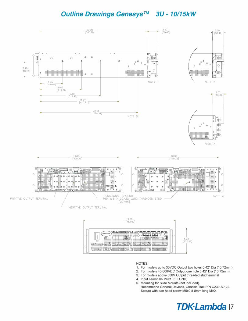
NOTES:1. For models up to 30VDC Output two holes 0.42" Dia (10.72mm)2. For models 40-300VDC Output one hole 0.42" Dia (10.72mm)3. For models above 300V Output threaded stud terminal 4. Input Terminals M6x1 (3 + GND)5. Mounting for Slide Mounts (not included). Recommend General Devices, Chassis Trak P/N C230-S-122. Secure with pan head screw M5x0.8-8mm long MAX.
J2 SW1
IN OUT
J1 J3
RS 485/232
TORQUE TERMINALTO 32 IN-LBS.
CAUTION:
(3.5NM)
J2
SW1
J1 J3
RS 485/232 OUT IN
TORQUE TERMINALCAUTION:
TO 32 IN-LBS. (3.5NM)
7
Outline Drawings GenesysTM 3U - 10/15kW
8
How to order
Accessories1. Serial Communication cableRS-232/RS-485 cable is used to connect the power supply to the Host PC.
2. Serial link cable*Daisy-chain up to 31 Genesys™ power supplies.
ModeRS-485
Power Supply Connector Communication CableEIA/TIA-568A (RJ-45) Shield Ground L=50cm GEN/RJ45
P/N
* Included with power supply
Mode
P/N
RS-485 RS-232 RS-232
GEN/485-9 GEN/232-9 GEN/232-25
PC ConnectorCommunication CablePower Supply Connector
RS-232/RS-485 Interface built-in Standard -GPIB (Multi-Drop Master) Interface IEMDMulti-Drop Slave Interface MDVoltage Programming Isolated Analog Interface IS510Current Programming Isolated Analog Interface IS420LAN Interface (Complies with Class C) LANUSB Interface USB