224
GENICOM 5050/5100 User’s Manual GEK-99031E

GENICOM
5050/5100 User’s ManualGEK-99031E

5050/5100 User’s Manual GEK-99044Eii
FCC COMPLIANCE STATEMENT (USA)This equipment complies with Part 15 of the FCC Rules. Operation issubject to the following two conditions: (1) This device may not causeharmful interference, and (2) this device must accept any interferencereceived, including interference that may cause undesired operation.If this equipment does cause harmful interference to radio ortelevision reception, which can be determined by turning theequipment off and on, the user is encouraged to try to correct theinterference by one or more of the following measures:
▪ Reorient or relocate the receiving antenna.
▪ Increase the separation between the equipment and receiver.
▪ Connect the equipment to an outlet on a circuit different fromthat to which the receiver is connected.
▪ Consult the dealer or an experienced radio/TV technician forhelp.
FCC warningChanges or modifications not expressly approved by the partyresponsible for compliance could void the user’s authority tooperate the equipment.
Note the following:
▪ The use of a non-shielded interface cable with the referenceddevice is prohibited.
▪ The length of the parallel interface cable must be 3 meters (10feet) or less.
▪ The length of the serial interface cable must be 15 meters (50 feet)or less.
▪ The length of the power cord must be 3 meters (10 feet) or less.
COMPLIANCE STATEMENT (CANADA)This digital apparatus is in conformity with standard NMB-003 ofCanada.
Cet appareil numérique est conforme à la norme NMB-003 duCanada.
COMPLIANCE STATEMENT (GERMANY)Bescheinigung des Herstellers/Importeurs:
Hermit wird bescheinigt, dass derMachinenlärminformationsverordnung 3. GSGV, 18.01.1991: Derhöchste Schalldruckpegel beträgt 70 dB (A) oder weniger gemäßEN27779-1991.

GEK-99044E Prefaceiii
COMPLIANCE STATEMENT (EUROPE)Warning
This product meets the interference requirements of EN55022.In a domestic environment, this product may cause radiointerference in which case, the user may be required to takeadequate measures.
Optional Interface KitsIf either of the Ethernet interface board, Token ring interface board,IBM TX/CX interface board, or any variation of the Legacy parallelboard is installed in either or both of the interface expansion slots,this equipment may produce additional radio frequency interferencein compliance with FCC Class A emissions.
Si des panneaux d’interface d’Ethernet, panneau de token ring,panneau d’IBM TX/CX, ou n’importe quelle variation des panneauxde parallèle de legs est installé dans l’un ou l’autre ou tous les deuxemplacements d’interface, ce matérial peut produire l’interférenceF.R. upplémentaire conformément ICES-003 aux émissions de laclasse A.
Falls Ethernet, Token ring, IBM TX/CX, Schnittstellenkarten odereine variation der herkoemmlicken Parallelscnittstellenkarten(interface) in einer oder beiden steckbaren Erweiterungsschnittstelleninstalliert sind, koennen moeglicherweise zusaetzlicheFunkfrequenzstoerungen erzeugt werden, unter Einhaltung derEN55022 Klasse A Stoerstrahlungswerte.
ENERGY STARAs an ENERGY STAR ® Partner, GENICOM has determined that thisproduct meets the ENERGY STAR ® guidelines for energy efficiency.The International ENERGY STAR ® Office Equipment Program is aninternational program that promotes energy saving through the useof computers and other office equipment. The program backs thedevelopment and dissemination of products with functions thateffectively reduce energy consumption. It is an open system in whichbusiness proprietors can participate voluntarily. The targetedproducts are office equipment such as computers, displays, printers,facsimiles, and copiers. Their standards and logos are uniform amongparticipating nations.

5050/5100 User’s Manual GEK-99044Eiv
INTERNATIONAL COMPLIANCEEN55022-1998 Emissions SeriesEN61000-3-2:1995 Power line harmonicsEN61000-3-3:1995 Power line flickerEN55024:1998 Immunity Characteristics
EN61000-4-2:1995 E.S.D.EN61000-4-3:1995 Radiated SusceptibilityEN61000-4-4:1995 E.F.T.EN61000-4-5:1995 SurgeEN61000-4-6:1996 R.F. Common modeEN61000-4-11:1994 Voltage dips and interruptions
Trademark AcknowledgementsGENICOM is a registered trademark of GENICOM L.L.C. Thefollowing companies own the other trademarks used in this manual:
GENICOM L.L.C.: Centronics;
International Business Machines Corporation: IBM;
Epson Corporation: Epson;
All other product names mentioned in this manual may also betrademarks of their respective companies.

GEK-99044E Table of Contentsv
Table of Contents PageCHAPTER 1. INTRODUCTION ...................................................................................................................... 1
REFERENCE USAGE:.......................................................................................................................................... 2ORGANIZATION OF THIS MANUAL..................................................................................................................... 2
CHAPTER 2. GETTING STARTED................................................................................................................ 3
PREPARING THE PRINTER FOR OPERATION ....................................................................................................... 3CONNECTING THE POWER CORD ...................................................................................................................... 4CONNECTING THE INTERFACE CABLE............................................................................................................... 4
I/O Interface Card Options available ....................................................................................................... 5DESCRIPTION OF THE CONTROL PANEL ............................................................................................................ 6
Beeper ....................................................................................................................................................... 7Display ...................................................................................................................................................... 7Keys........................................................................................................................................................... 7
OPERATION OF THE CONTROL PANEL............................................................................................................... 8Data Entry................................................................................................................................................. 9
INSTALLING THE PAPER HANDLING SYSTEM.................................................................................................. 10(55 OR 60 DBA CABINET MODELS) ................................................................................................................. 10SELECTING THE PAPER PATH.......................................................................................................................... 125050/5100 (55 AND 60 DBA) CABINET MODEL ONLY ................................................................................ 12
Wire Paper Guide ................................................................................................................................... 13LOADING PAPER............................................................................................................................................. 15
Manual Paper Loading ........................................................................................................................... 15Semiautomatic Paper Loading................................................................................................................ 19
HORIZONTAL POSITIONING OF THE PAPER...................................................................................................... 20THE RIBBON DECK......................................................................................................................................... 21THE RIBBON CARTRIDGE................................................................................................................................ 22RIBBON INSTALLATION AND REMOVAL ......................................................................................................... 22
Removing a Ribbon ................................................................................................................................. 25SETTING THE PRINT GAP ................................................................................................................................ 26
Reading the Scale.................................................................................................................................... 26Using the White Scale ........................................................................................................................................26Using the Black Scale ........................................................................................................................................27
PAPER TENSION ADJUSTMENT........................................................................................................................ 27POWER-ON SEQUENCE ................................................................................................................................... 28TEST PATTERN PRINTING................................................................................................................................. 28
CHAPTER 3. OPERATING THE PRINTER................................................................................................ 30
PRINTER OPERATIONAL MODES...................................................................................................................... 30Online...................................................................................................................................................... 30Offline ..................................................................................................................................................... 30Fault........................................................................................................................................................ 30Menu ....................................................................................................................................................... 30
Status Display.....................................................................................................................................................30MAIN MENU................................................................................................................................................... 31
Operator Menu........................................................................................................................................ 31Setup Menu.............................................................................................................................................. 31Maintenance Menu.................................................................................................................................. 31Menu Control .......................................................................................................................................... 32
SETTING UP A FORMAT................................................................................................................................... 32Active Format.......................................................................................................................................... 32Setting up the Active Format................................................................................................................... 33Form Length............................................................................................................................................ 33Top Print Ref........................................................................................................................................... 33
5050/5100 User’s Manual GEK-99044Evi
Table of Contents PageCHAPTER 3. OPERATING THE PRINTER (CONTINUED)
LOW PAPER PRINTING .................................................................................................................................... 34Low Paper ............................................................................................................................................... 34Replenishing Paper Supply ..................................................................................................................... 35
SETTING TOP OF FORM.................................................................................................................................... 36PAPER TEAR-OFF FEATURE............................................................................................................................ 37
Paper Path (55 or 60 dBa Cabinet Model Only)..................................................................................... 37LOCAL AUTO VIEW FEATURE......................................................................................................................... 37
Viewing.................................................................................................................................................... 37Retracting................................................................................................................................................ 37
THE INTERLOCK CIRCUIT................................................................................................................................ 38INITIALIZING THE PRINTER ............................................................................................................................. 38
When to Initialize .................................................................................................................................... 38USING THE KEYPAD TO INITIALIZE................................................................................................................. 39
Control Panel Initialization .................................................................................................................... 40USING THE MENU CONTROL MENU ................................................................................................................. 41
CHAPTER 4. USING THE OPERATOR MENU ......................................................................................... 42
NEW RIBBON.................................................................................................................................................. 42SHOW ............................................................................................................................................................. 42
Software IDs............................................................................................................................................ 43Sample Status Page ................................................................................................................................. 43Sample Format Page............................................................................................................................... 46Sample Code Page .................................................................................................................................. 48Sample Font Page ................................................................................................................................... 48
TEST PATTERN ............................................................................................................................................... 50DISCARD JOB.................................................................................................................................................. 50
CHAPTER 5. USING THE SET UP MENU .................................................................................................. 51
FORMAT ......................................................................................................................................................... 51Modify Format ........................................................................................................................................ 52
Format Name......................................................................................................................................................52Font Style ...........................................................................................................................................................53Code Pg/Country................................................................................................................................................53
Code Page ...................................................................................................................................................54Country .......................................................................................................................................................54
CPI .....................................................................................................................................................................55LPI .....................................................................................................................................................................55Form Length.......................................................................................................................................................56Left Margin ........................................................................................................................................................57Right Margin......................................................................................................................................................58Top Print Ref......................................................................................................................................................59Left Print Ref .....................................................................................................................................................60Horiz Expansion.................................................................................................................................................61Vert Expansion...................................................................................................................................................62VertExp Options ................................................................................................................................................63Print Modifiers ...................................................................................................................................................64Print Options ......................................................................................................................................................65Print Control.......................................................................................................................................................66
Define LF ....................................................................................................................................................66Define CR ...................................................................................................................................................66Define FF ....................................................................................................................................................67Define HT ...................................................................................................................................................67VertMove ....................................................................................................................................................67AutoWrap....................................................................................................................................................68

GEK-99044E Table of Contentsvii
Table of Contents PageCHAPTER 5. USING THE SET UP MENU (CONTINUED)
FF @ TOF...................................................................................................................................................68GENPTROPTS ..................................................................................................................................................69Slew Rate ...........................................................................................................................................................69
Save Format ............................................................................................................................................ 70SELECT I/F ..................................................................................................................................................... 71I/F SETTINGS.................................................................................................................................................. 71
MultiSource............................................................................................................................................. 72Parallel Setup.......................................................................................................................................... 73Serial ....................................................................................................................................................... 74
Serial Type .........................................................................................................................................................74Serial Setup ........................................................................................................................................................75
Protocol .......................................................................................................................................................75XON/XOFF.................................................................................................................................................76CD(DTR) ....................................................................................................................................................76CA(RTS) .....................................................................................................................................................77SCA(SRTS).................................................................................................................................................77ETX/ACK ...................................................................................................................................................78Inhibit Xmit.................................................................................................................................................78Lead Polarity ...............................................................................................................................................79Data Bits......................................................................................................................................................79Parity ...........................................................................................................................................................80Stop Bits......................................................................................................................................................81Baud Rate....................................................................................................................................................81High Trip Pt% .............................................................................................................................................82
Expansion1/Expansion2.......................................................................................................................... 83Legacy Parallel...................................................................................................................................................83
Centronics ...................................................................................................................................................84DP(Short) ....................................................................................................................................................84DP(Long) ....................................................................................................................................................85I/F Straps.....................................................................................................................................................85
Token Ring.........................................................................................................................................................86Coax ...................................................................................................................................................................86Twinax ...............................................................................................................................................................87TCP/IP................................................................................................................................................................88Netware ..............................................................................................................................................................89
IBM Host Status ...................................................................................................................................... 90SELECT FILTER............................................................................................................................................... 91FILTER SETTINGS............................................................................................................................................ 93
IGP.......................................................................................................................................................... 93BC Density.........................................................................................................................................................93Control Chars .....................................................................................................................................................94Language............................................................................................................................................................94IGP Terminator ..................................................................................................................................................95Quiet Mode ........................................................................................................................................................95Delete Logos ......................................................................................................................................................95Default OCR-B...................................................................................................................................................96Vertical DPI .......................................................................................................................................................96Slashed Zero.......................................................................................................................................................96Clip Text ............................................................................................................................................................97Ignore Chr Mode ................................................................................................................................................97Ignore Char ........................................................................................................................................................98Form Length=0...................................................................................................................................................98Ignore Term........................................................................................................................................................99
QMS ........................................................................................................................................................ 99BC Density.........................................................................................................................................................99Control Chars ...................................................................................................................................................100

5050/5100 User’s Manual GEK-99044Eviii
Table of Contents PageCHAPTER 5. USING THE SET UP MENU (CONTINUED)
Language..........................................................................................................................................................100Code V .............................................................................................................................................................101Free Format ......................................................................................................................................................101Ignore Mode.....................................................................................................................................................101Slashed Zero.....................................................................................................................................................102PY Terminator..................................................................................................................................................102PN Terminator..................................................................................................................................................102Vertical DPI .....................................................................................................................................................103LPI Grid ...........................................................................................................................................................103Version.............................................................................................................................................................103Magnum Spaces ...............................................................................................................................................104Ignore Chr Mode..............................................................................................................................................104Ignore Char ......................................................................................................................................................105
IPDS ...................................................................................................................................................... 105IPDS BC Stagger .............................................................................................................................................105IPDS BC Density .............................................................................................................................................106IPDS GR Density .............................................................................................................................................106IPDS Im Density ..............................................................................................................................................106IPDS Text.........................................................................................................................................................107IPDS Dens Ovr.................................................................................................................................................107
IBM Format........................................................................................................................................... 107Code Page ........................................................................................................................................................108Code Pg Override.............................................................................................................................................108Draft = High Speed ..........................................................................................................................................108LPI ...................................................................................................................................................................109LPI Override ....................................................................................................................................................109CPI ...................................................................................................................................................................109CPI Override ....................................................................................................................................................110MPP .................................................................................................................................................................110MPP Override ..................................................................................................................................................111MPL .................................................................................................................................................................111MPL Override ..................................................................................................................................................112SCS Text ..........................................................................................................................................................112Override Text ...................................................................................................................................................112Override All .....................................................................................................................................................113Hex Print ..........................................................................................................................................................113Hex 1................................................................................................................................................................114Hex 2................................................................................................................................................................115Hex Term .........................................................................................................................................................115DCF 1...............................................................................................................................................................115DCF 2...............................................................................................................................................................116DCF Term ........................................................................................................................................................117ASCII Driver....................................................................................................................................................117Print Direction..................................................................................................................................................117Coax Compat....................................................................................................................................................118
Case...........................................................................................................................................................118LOC Copy FF............................................................................................................................................118FF Before LC ............................................................................................................................................119Interv Req..................................................................................................................................................119Irq Err TO .................................................................................................................................................120Irq Bsy TO ................................................................................................................................................120CR at MPP+1 ............................................................................................................................................121NL at MPP+1 ............................................................................................................................................121FF Data .....................................................................................................................................................122FF EndBuff ...............................................................................................................................................122Null Sup ....................................................................................................................................................123FF Pos .......................................................................................................................................................123

GEK-99044E Table of Contentsix
Table of Contents PageCHAPTER 5. USING THE SET UP MENU (CONTINUED)
Auto Funct.................................................................................................................................................123LAST LF/FF .............................................................................................................................................124Supp CCode ..............................................................................................................................................124VCS...........................................................................................................................................................124Comm........................................................................................................................................................125
SELECT EMUL............................................................................................................................................... 126EMUL SETTINGS ........................................................................................................................................... 127
ANSI (4800)........................................................................................................................................... 127ANSI (4410)........................................................................................................................................... 127FX286E ................................................................................................................................................. 128Proprinter.............................................................................................................................................. 128P 300/600 .............................................................................................................................................. 129DEC LG................................................................................................................................................. 129Pseries................................................................................................................................................... 130DEC PPL3............................................................................................................................................. 130
ENGINE OPTIONS.......................................................................................................................................... 131Direction ............................................................................................................................................... 131EngineOff Delay.................................................................................................................................... 131Print Intensity........................................................................................................................................ 132
TEAROFF OPTIONS....................................................................................................................................... 133Path ....................................................................................................................................................... 134Retract................................................................................................................................................... 134Auto ....................................................................................................................................................... 135
HORIZ TAB................................................................................................................................................... 136VERTICAL FORMAT ...................................................................................................................................... 137
Vertical Tabs ......................................................................................................................................... 137Emulation VFU ..................................................................................................................................... 138
DISPLAY LAN ............................................................................................................................................... 138
CHAPTER 6. USING THE MAINTENANCE MENU ............................................................................... 139
RESET TO DEFLTS......................................................................................................................................... 140ALIGNMENT ................................................................................................................................................. 141
Patterns ................................................................................................................................................. 141AdjustAmplitude .................................................................................................................................... 143
POWER ON TIME........................................................................................................................................... 144PRINT TIME .................................................................................................................................................. 144RIBBONMONITOR......................................................................................................................................... 145HEADSERVICE.............................................................................................................................................. 146
Dot Counts ............................................................................................................................................ 146Print Chart ............................................................................................................................................ 147Actuator Status...................................................................................................................................... 147
UPGRADE FLASH .......................................................................................................................................... 148
CHAPTER 7. OPERATOR CARE AND MAINTENANCE ...................................................................... 149
INTRODUCTION............................................................................................................................................. 149OPERATOR CLEANING PROCEDURES ............................................................................................................ 149OPERATOR TROUBLESHOOTING ................................................................................................................... 150
Soft Faults ............................................................................................................................................. 152Miscellaneous Non-Fault Messages...................................................................................................... 155Hard Faults ........................................................................................................................................... 156Electrical Problems............................................................................................................................... 158Mechanical Problems............................................................................................................................ 159

5050/5100 User’s Manual GEK-99044Ex
Table of Contents PageCHAPTER 7. OPERATOR CARE AND MAINTENANCE (CONTINUED)
Self-Test Error Messages ...................................................................................................................... 160SERIAL INTERFACE ERRORS.......................................................................................................................... 161PRINT HEAD REPLACEMENT......................................................................................................................... 161
Replacement Procedure ........................................................................................................................ 162Resetting Print Head Counters.............................................................................................................. 165
APPENDIX A UNPACKING INSTRUCTIONS .......................................................................................... 167
UNPACKING (5050/5100 50 DBA MODEL).................................................................................................... 167Unpacking (5050/5100 55 or 60 dBa Model)........................................................................................ 170Repacking.............................................................................................................................................. 172
APPENDIX B PAPER SPECIFICATIONS .................................................................................................. 173
RECOMMENDED PAPER WEIGHTS................................................................................................................. 173
APPENDIX C CONSIDERATIONS FOR OPERATION ........................................................................... 175
APPENDIX D................................................................................................................................................... 177
PARTS, ACCESSORIES, CONSUMABLES AND OPTIONS ................................................................... 177
APPENDIX E. FONT PRINT SAMPLES ..................................................................................................... 178
APPENDIX F. FLASH UPGRADE INSTRUCTIONS ................................................................................ 181
On Board Software to External Flash SIMM ........................................................................................ 182
APPENDIX G DESCRIPTION OF STRAPPING OPTIONS..................................................................... 183
GENERAL PRINTER OPTIONS DEFINITIONS ................................................................................................... 184LEGACY PARALLEL HARDWARE STRAP DEFINITIONS.................................................................................... 186LEGACY PARALLEL SOFTWARE STRAP DEFINITIONS.................................................................................... 188EMULATION OPTION DESCRIPTIONS ............................................................................................................. 189
APPENDIX H. INTERFACE, EMULATION AND FILTER INFORMATION....................................... 193
PRINTER INTERFACES ................................................................................................................................... 193Parallel and Serial Interfaces ............................................................................................................... 193Multisource Timeout ............................................................................................................................. 193IEEE 1284 Bi-directional Parallel Port................................................................................................ 193Parallel Interface Pin Assignments ....................................................................................................... 194Parallel Interface Timing ...................................................................................................................... 195RS-232 Serial Interface ......................................................................................................................... 195
Serial Port Configuration .................................................................................................................................196RS-232 Pin Assignments..................................................................................................................................196
RS-422 Interface.................................................................................................................................... 197RS-422 Pin Assignment ...................................................................................................................................197Troubleshooting the RS-422 ............................................................................................................................198Lead Polarities..................................................................................................................................................198Troubleshooting the RS-422 Interface .............................................................................................................199
PRINTER EMULATIONS AND FILTERS ............................................................................................................ 200PRINTER EMULATIONS AND TAB ID SLOTS................................................................................................... 201FILTER COMBINATIONS................................................................................................................................. 202
APPENDIX I. LCD MENU MAPS................................................................................................................. 203

5050/5100 User’s Manual Chapter 1. Introduction1
CHAPTER 1. INTRODUCTIONThis printer is a high duty cycle, line matrix printer. Among theadvanced features of this printer are:
▪ High speed at 500/1000 lpm
▪ Industry’s only lifetime warranty on shuttle mechanism andstriker bar
▪ IBM-compatible models
▪ Ideal for manufacturing pick lists and shipping documents
▪ Remote network printing
▪ Auto interface switching
▪ Top demand exit or rear exit standard (5050/5100 (55 or 60 dBa)Cabinet Model)
▪ Industrial graphics, bar codes, and labels
Other characteristics include:
Input voltage:
▪ 5050/5100 Models auto range selecting 115V or 230V
▪ Hardware interfaces: menu selectable or auto switching betweenCENTRONICS parallel and RS-232 serial
▪ Standard emulations: menu- or host-selectable ANSI 4800, ANSI4410, Epson FX286e, IBM Proprinter III XL, P 300/600, DEC LGand PPL3, and Pseries.
▪ Standard fonts: menu- or host-selectable Data Processing,Correspondence, Gothic NLQ, Graphics, Courier NLQ, Italic NLQ,High Speed, OCR-A, OCR-B and Oversize.

5050/5100 User’s Manual GEK-99044E2
REFERENCE USAGE:Warning
Warning is used to alert a user of a hazard that could causepersonal injury or severe damage to the equipment.
CautionCaution is used where there is a risk of damaging the equipment,parts or supplies.
Note
Indicates additional information.
For clarity, if a procedure or information is presented which isapplicable to a specify cabinet model, a small graphic icon on thecabinet model is placed near the text. (See pictures below.)
ORGANIZATION OF THIS MANUALThis User’s Manual covers the 5050/5100 model printers. Someprocedures discussed in this manual are cabinet specific. Thedifferences are noted within sections where possible and separatedinto sections where necessary. The following is a visualrepresentation of the cabinet models available:
Quietized Cabinet5050/5100 (50 dBa)
Closed Pedestal Cabinet5050/5100 (55 dBa)
Open Pedestal Cabinet5050/5100 (60 dBa)
5050/5100 CABINET STYLES AND MODEL NUMBERS
5050/5100 User’s Manual Chapter 2.Getting Started3
CHAPTER 2. GETTING STARTED
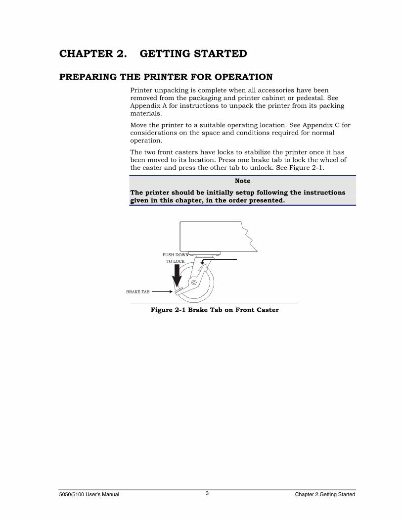
PREPARING THE PRINTER FOR OPERATIONPrinter unpacking is complete when all accessories have beenremoved from the packaging and printer cabinet or pedestal. SeeAppendix A for instructions to unpack the printer from its packingmaterials.
Move the printer to a suitable operating location. See Appendix C forconsiderations on the space and conditions required for normaloperation.
The two front casters have locks to stabilize the printer once it hasbeen moved to its location. Press one brake tab to lock the wheel ofthe caster and press the other tab to unlock. See Figure 2-1.
NoteThe printer should be initially setup following the instructionsgiven in this chapter, in the order presented.
Figure 2-1 Brake Tab on Front Caster
BRAKE TAB
PUSH DOWN
TO LOCK

5050/5100 User’s Manual GEK-99044E4
CONNECTING THE POWER CORDThe 5050/5100 (50, 55 or 60 dBa) Cabinet Model printer is equippedwith an auto-switching power supply and can be connected to eithera 115V or 230V source without damage or manually changing aswitch setting.
The allowable voltage variation is ±15% and the allowable frequencyis 48 to 65 Hz.
A power cord is packed with the printer. Plug the female end of thecord into the recessed connector at the rear of the printer. See Figure2-2. Plug the other end into a compatible, properly grounded ACoutlet.
Avoid using AC circuits serving other equipment which may causechronic low voltage, noise interference, or power fluctuations. Dataloss may result.
Note
The AC outlet must be rated for at least 10-ampere service.
CONNECTING THE INTERFACE CABLEBoth a 25-pin RS-232C serial interface connector and a 36-pinCENTRONICS parallel interface connector are standard on thisprinter. Both connectors are located on the data connector plate onthe rear of the printer. See Figure 2-2.
FIGURE 2-2 REAR VIEW OF PRINTER5050/5100 (55 dBa) MODEL
POWER ON/OFF(I/O) SWITCH
RECESSED CONNECTORI/O CARDINTERFACE SLOTS
25-PIN SERIALCONNECTOR
36-PIN PARALLELCONNECTOR
FUSE HOLDER
POWER CORD

5050/5100 User’s Manual Chapter 2.Getting Started5
I/O Interface Card Options availableThere are two expansion slots located in the rear of the printer. Theinterface options available are:
▪ Legacy parallel
▪ DPSL (Dataproducts short line)
▪ DPLL (Dataproducts long line)
▪ IBM/TX/CX
▪ Ethernet (10/100, 10baseT, and Token Ring)

5050/5100 User’s Manual GEK-99044E6
DESCRIPTION OF THE CONTROL PANELThe control panel is mounted in the top of the printer and isaccessible with the top cover either open or closed. The Control Panelutilizes a display panel composed of two rows of sixteen characterseach. With the top cover open, the control panel will move aroundslightly to the touch. This is normal. The floating mount allows thepanel to align itself when the top cover is closed.
The basic look and layout of the 5050/5100 control panel isrepresented by the following:
The four keys to the right of the display are to navigate the menu treestructure and are referred as menu browse keys. The On Line/Off Linekey is located at the top of the left row of keys. The three keys belowthe On Line/Off Line key,↑ (up arrow), ↓ (down arrow), and TOF, areused to set top of form. See “Setting Top of Form” in Chapter 3 foradditional information. The bottom left key, Format (in conjunctionwith the Select key), is used to select one of ten stored formats. TheFF, Tear Off, and View keys under the display are additional paperpositioning functions. The Clear and Select keys are used in dataentry and menu operations.
In the online state, only the FF, On Line/Off Line, Tear Off, & Viewkeys and limited functionality of the Clear and Select keys are active.Pressing any other key causes a “beep.” The “Processing” LEDindicator is lit whenever data is being received and or beingprocessed/printed. In multi-source I/O mode, the “Processing” LEDindicator will blink for the duration of the timeout period whenprocessing is complete. The processing LED indicator lights shouldbe unlit before making menu changes.
NoteThe control panel mount on the 5050/5100 is hinged so that itcan be tilted forward to remove the ribbon deck for service.

5050/5100 User’s Manual Chapter 2.Getting Started7
BeeperThe control panel beeper sounds momentarily when:
▪ A key is pressed.
▪ A BEL control code is received.
▪ A PAPER LOW condition exists.
▪ An EVFU loading error occurs. (For more information on theEVFU, see the Programmer’s Manual.)
▪ A hard fault occurs. (See Chapter 7 for an explanation of hardfaults.)
▪ If SCS or IPDS software is loaded in the printer, the beeper willsound on receipt of an SCS or IPDS bell code.
DisplayThe two row by sixteen-character LCD provide the followinginformation:
▪ The printer’s status - Online, Local, Self-test, etc.
▪ Which menu or menu option is presently on display to assist inmaking selections.
▪ Fault messages.
▪ If SCS or IPDS software is loaded in the printer, the display canshow coax and twinax status messages. Refer to the Setup Menu| Interface Settgs | IBM Host Status.
KeysThe keys are raised rubber-type switches used to make menuselections, clear faults, and position the paper. An explanation of thekeys’ functions is given in the following section on “Operation of theControl Panel.”
5050/5100 User’s Manual GEK-99044E8
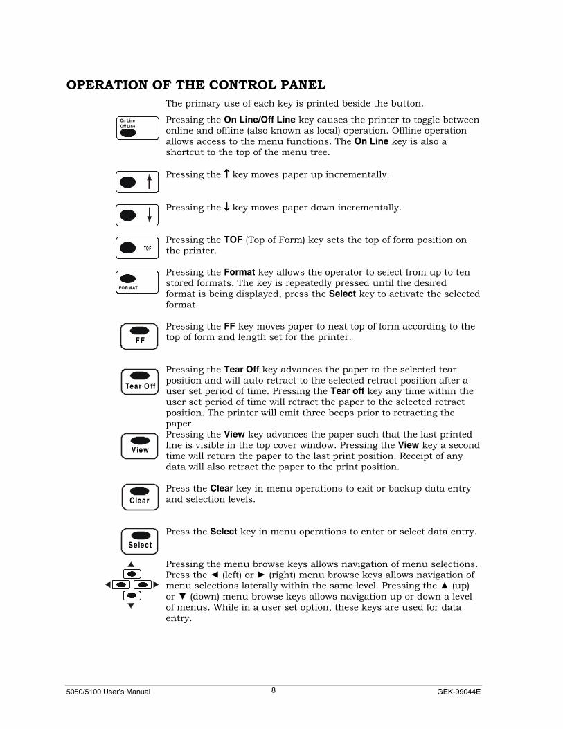
OPERATION OF THE CONTROL PANELThe primary use of each key is printed beside the button.
Pressing the On Line/Off Line key causes the printer to toggle betweenonline and offline (also known as local) operation. Offline operationallows access to the menu functions. The On Line key is also ashortcut to the top of the menu tree.
Pressing the ↑↑↑↑ key moves paper up incrementally.
Pressing the ↓↓↓↓ key moves paper down incrementally.
Pressing the TOF (Top of Form) key sets the top of form position onthe printer.
Pressing the Format key allows the operator to select from up to tenstored formats. The key is repeatedly pressed until the desiredformat is being displayed, press the Select key to activate the selectedformat.
Pressing the FF key moves paper to next top of form according to thetop of form and length set for the printer.
Pressing the Tear Off key advances the paper to the selected tearposition and will auto retract to the selected retract position after auser set period of time. Pressing the Tear off key any time within theuser set period of time will retract the paper to the selected retractposition. The printer will emit three beeps prior to retracting thepaper.Pressing the View key advances the paper such that the last printedline is visible in the top cover window. Pressing the View key a secondtime will return the paper to the last print position. Receipt of anydata will also retract the paper to the print position.
Press the Clear key in menu operations to exit or backup data entryand selection levels.
Press the Select key in menu operations to enter or select data entry.
Pressing the menu browse keys allows navigation of menu selections.Press the ◄ (left) or ► (right) menu browse keys allows navigation ofmenu selections laterally within the same level. Pressing the ▲ (up)or ▼ (down) menu browse keys allows navigation up or down a levelof menus. While in a user set option, these keys are used for dataentry.
On LineOff Line
FORM AT
TO F
Tear O ff
FF
View
Clear
Select

5050/5100 User’s Manual Chapter 2.Getting Started9
Data EntryThere are two modes of data entry for the control panel. The firstmode is to select from a list of several options displayed on thebottom line of the LCD. The entries are sequentially displayed on thebottom line of the LCD in response to browse keys ( ◄ and ► ). Theoptional selections are shown as a circular list. For example, inselecting CPI, the choices 10, 12<, 13.3, 15, 16.7, 17.1, 20, and XX.XUSER SET will be displayed sequentially. If one of the displayedvalues (i.e. numbers) are selected (other than the XX.X USER SET)the selection process is completed by depressing the Select key.
NoteThe current setting is marked with the < symbol (12< shownabove.)
In USER SET mode the display switches to a format where theoperator may enter any value 0 to 9 for any “X” position. The fourmenu browse keys revert to data entry operation. The horizontal ◄►(left or right) keys position the cursor (underline) to the digit to bechanged; the vertical ▲▼(up or down) keys increment/decrement theselected digit by one. In the example used previously, 12 CPI wasactive when the selection process was entered (shown above as 12<).The operator selected from the list, the XX.X USER SET. The displayshows 12.0, where the underline indicates the active digit, and where12.0 is the current CPI value. Depressing the up menu browse keyincrements that digit from 12.0 to 22.0 or higher, where only the firstdigit increments. Depressing the right arrow key moves the cursorfrom 22.0 to 22.0. Depressing the right arrow again moved the cursorfrom from 22.0 to 22.0 (the decimal point is automatically skippedover). Depressing the right down arrow key changes the decimalvalue from 20.0 to 20.9 (the values wrap 0 1 2 3 4 5 6 7 8 9 etc).
NoteSince the four menu browse keys are used to make this type ofentry, use the Select key or Clear key to exit this type of dataentry. If the Select key is pressed, the display shows theselection as from above: 22.9 USER SET. If the Clear key is used,the menu entry returns to the previous (higher) level showingXX.X User Set as above without changing the CPI.
5050/5100 User’s Manual GEK-99044E10
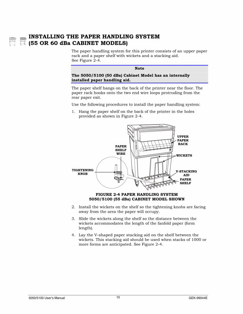
INSTALLING THE PAPER HANDLING SYSTEM(55 OR 60 dBa CABINET MODELS)
The paper handling system for this printer consists of an upper paperrack and a paper shelf with wickets and a stacking aid.See Figure 2-4.
NoteThe 5050/5100 (50 dBa) Cabinet Model has an internallyinstalled paper handling aid.
The paper shelf hangs on the back of the printer near the floor. Thepaper rack hooks onto the two end wire loops protruding from therear paper exit.
Use the following procedures to install the paper handling system:
1. Hang the paper shelf on the back of the printer in the holesprovided as shown in Figure 2-4.
2. Install the wickets on the shelf so the tightening knobs are facingaway from the area the paper will occupy.
3. Slide the wickets along the shelf so the distance between thewickets accommodates the length of the fanfold paper (formlength).
4. Lay the V-shaped paper stacking aid on the shelf between thewickets. This stacking aid should be used when stacks of 1000 ormore forms are anticipated. See Figure 2-4.
PAPERSHELFWIRE
TIGHTENINGKNOB
PAPERSHELF
V-STACKINGAID
WICKETS
UPPERPAPERRACK
FIGURE 2-4 PAPER HANDLING SYSTEM5050/5100 (55 dBa) CABINET MODEL SHOWN

5050/5100 User’s Manual Chapter 2.Getting Started11
5. Hook the paper rack onto the two end wire loops protruding fromthe rear paper exit. See Figure 2-5.
6. After the rack is hooked into place, swing it up as shown in theillustration on the left and connect the two static ground wires.See Figure 2-6.
Figure 2-6 Side Views5050/5100 (55 and 60 dba) CABINET model
STATICGROUND WIRECONNECTOR
(TWO PLACES)
FINISHEDINSTALLATION
SWING RACK UP
Figure 2-5 Rear View5050/5100 (55 and 60 dba) CABINET Model shown
RIGHT ENDWIRE LOOPLEFT END
WIRE LOOP
5050/5100 User’s Manual GEK-99044E12
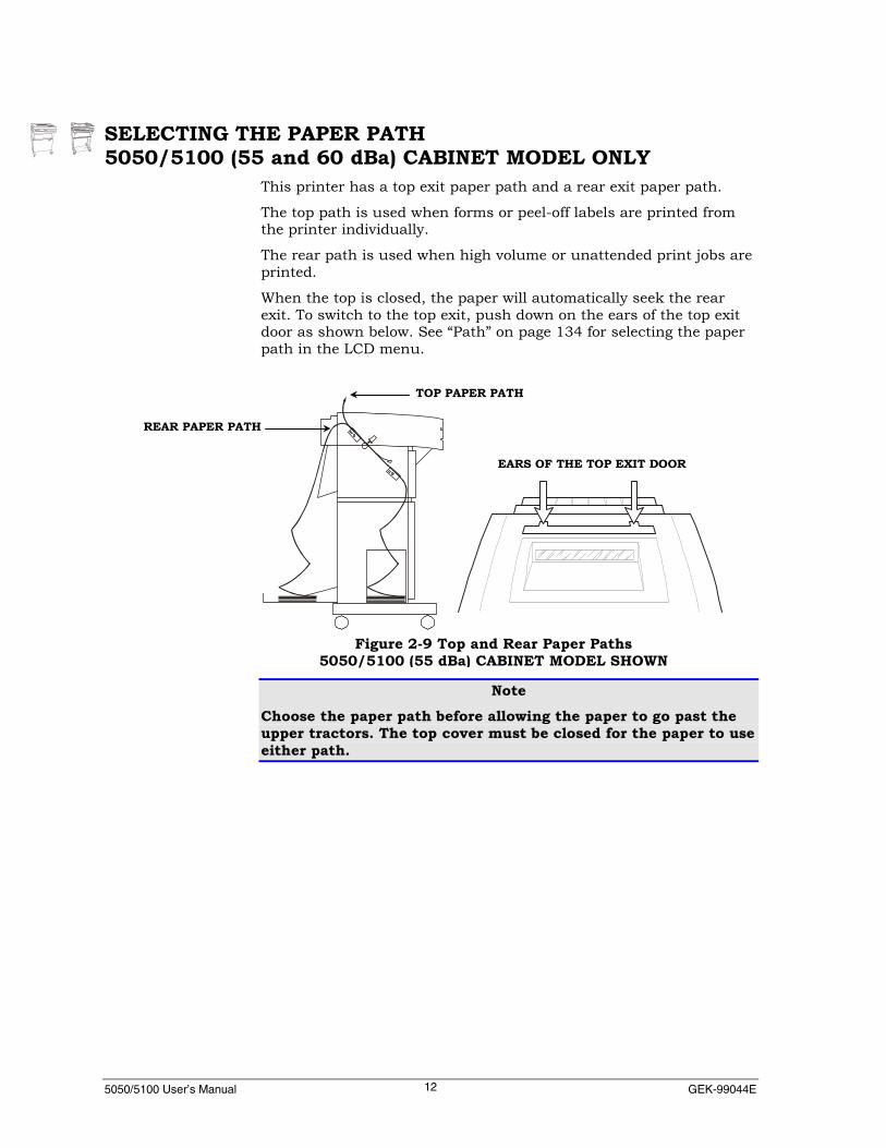
SELECTING THE PAPER PATH5050/5100 (55 and 60 dBa) CABINET MODEL ONLY
This printer has a top exit paper path and a rear exit paper path.
The top path is used when forms or peel-off labels are printed fromthe printer individually.
The rear path is used when high volume or unattended print jobs areprinted.
When the top is closed, the paper will automatically seek the rearexit. To switch to the top exit, push down on the ears of the top exitdoor as shown below. See “Path” on page 134 for selecting the paperpath in the LCD menu.
NoteChoose the paper path before allowing the paper to go past theupper tractors. The top cover must be closed for the paper to useeither path.
Figure 2-9 Top and Rear Paper Paths5050/5100 (55 dBa) CABINET MODEL SHOWN
EARS OF THE TOP EXIT DOOR
REAR PAPER PATH
TOP PAPER PATH

5050/5100 User’s Manual Chapter 2.Getting Started13
Wire Paper GuideThe printer is shipped with a wire paper guide installed. The purposeof this part is to prevent paper jams when the rear (default) paper exitis used.
To thread paper through the rear exit, lift up the paper guide until itsticks to the magnet on the top cover. See Figure 2-10.
NoteTo have paper exit through the top (5050/5100 (55 or 60 dBa)Cabinet Model only), the paper guide must be removed. Placing ahand under the paper guide at the left end, lift up and away at anangle. See Figure 2-11a. Placing a hand under the right side ofthe paper guide, lift up and toward the front of the printer. SeeFigures 2-11b and 2-11c.
Figure 2-10 Wire Paper Guide 5050/5100 (55 or 60 DbA) cabinet Model)
PAPER GUIDE
MAGNET
FIGURE 2 - 11a FIGURE 2 - 11b FIGURE 2 - 11c

5050/5100 User’s Manual GEK-99044E14
If the rear exit paper path is used without the paper guide installed,paper may jam in the top cover.
To re-install the paper guide, find the wires that are closest togetheron the left end. Install the guide so that these two wires straddle theleft mounting bracket. This holds the part in place horizontally. Thesmall ring on the paper guide slides onto the corresponding prong onthe paper deflector.
FIGURE 2-12 REINSTALLING THE PAPER GUIDE(LEFT VIEW)
PRONG
LEFTMOUNTINGBRACKET
PAPERGUIDE
TWOWIRES
CLOSESTTOGETHER

5050/5100 User’s Manual Chapter 2.Getting Started15
LOADING PAPERThis printer is designed to use edge-punched (sprocket, or pin-fed)fanfold paper. See “Paper Specifications” in Appendix B for furtherdescription of the types of paper that can be used in the printer.
CautionPrinting without paper or using paper too narrow for the job maydamage printer components and void the printer warranty. Full-width paper (greater than 14 5/8-inch or 371cm) should be useduntil the operator is familiar with the printer’s setup andoperation.
Manual Paper LoadingTo load paper in the printer, complete the following steps:
1. Raise the top cover to the open position. On 5050/5100 (55 or 60dBa) Cabinet Model printers, press the front latch to unlock thecover. See Figure 2-13.
2. Turn the print gap wheel to the LOAD position by pushing the topof the wheel towards the rear of the printer until it stops. SeeFigure 2-14.
NoteIf the power has been applied to the printer, the fault messagesPaper Out and Strikr Bar Open will appear on the display panel andthe beeper will sound. These will alternately display in the upperleft corner of the display panel until the CLEAR key is pressedafter the paper has been loaded and the gap wheel positioned towithin the normal operating zone.
Paper Out
Strikr Bar Open
FRONT LATCH
FIGURE 2-13 FRONT VIEW OF PRINTER5050/5100 (55 or 60 dBa) CABINET MODEL SHOWN

5050/5100 User’s Manual GEK-99044E16
3. Push the paper tension adjustment lever down to position 1. SeeFigure 2-14.
4. Open the top left and right tractor doors. See Figure 2-15.
5. Open the front door and place the paper supply in the enclosure.
NoteEither cut the top off the box of paper or tape the flaps down toprevent snagging the paper as it leaves the box.
FIGURE 2-14 PRINT GAP WHEEL IN LOAD
PRINT GAPWHEEL
PAPERTENSIONLEVER
FIGURE 2-15 TOP VIEW OF PRINTER 5050/5100 (55 dBa) CABINET MODEL SHOWN)
UPPERLEFT
TRACTOR
UPPERRIGHT
TRACTOR

5050/5100 User’s Manual Chapter 2.Getting Started17
6. On 5050/5100 (55 or 60 dBa) Cabinet Model printers, grasp thebottom edge of the front access panel of the printer and lift it tothe open position. A magnetic latch will hold the panel open. SeeFigure 2-16.
7. Open the lower left and right tractor doors. See Figure 2-17
NoteTo load single-part paper, fold the paper over at a perforation sothat the first two forms are double-thick. Later, when printerpower is on, feed these doubled forms out of the printer beforeadjusting the print gap.
FIGURE 2-16 FRONT ACCESS PANEL AND FRONT CABINET DOOR OPEN
FRONT ACCESS PANEL
FRONT COVER DOOR
LOWERTRACTOR
DOORS
LOWERTRACTOR
DOORS
FIGURE 2-17 LOWER TRACTOR DOORS
LOWERTRACTOR
DOORS
5050/5100 User’s Manual GEK-99044E18
8. Hand feed the paper, bypassing the lower tractor pins, upthrough the printer to the top tractors. After the printer is inoperation, the semiautomatic paper loading feature may be used.
NoteInitially, load the paper so that it will print on the second form(rather than first form) because a default setting pulls the paperdown into the printer a minimum of 4 inches (see “Setting Topof Form”). Later, vertical positioning and top of form (TOF)alignment will be completed after the printer is in operation.
9. Place the paper onto the pins of the upper left tractor and closethe tractor door.
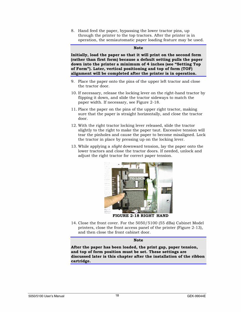
10. If necessary, release the locking lever on the right-hand tractor byflipping it down, and slide the tractor sideways to match thepaper width. If necessary, see Figure 2-18.
11. Place the paper on the pins of the upper right tractor, makingsure that the paper is straight horizontally, and close the tractordoor.
12. With the right tractor locking lever released, slide the tractorslightly to the right to make the paper taut. Excessive tension willtear the pinholes and cause the paper to become misaligned. Lockthe tractor in place by pressing up on the locking lever.
13. While applying a slight downward tension, lay the paper onto thelower tractors and close the tractor doors. If needed, unlock andadjust the right tractor for correct paper tension.
14. Close the front cover. For the 5050/5100 (55 dBa) Cabinet Modelprinters, close the front access panel of the printer (Figure 2-13),and then close the front cabinet door.
NoteAfter the paper has been loaded, the print gap, paper tension,and top of form position must be set. These settings arediscussed later is this chapter after the installation of the ribboncartridge.
FIGURE 2-18 RIGHT HAND
TO LOCK

5050/5100 User’s Manual Chapter 2.Getting Started19
Semiautomatic Paper LoadingOnce the printer’s tractors have been set up for the specific paperbeing used and power has been applied; the semiautomatic paperloading feature may be used.
After the paper is loaded in the lower tractors, pressing the FF (formfeed) key causes the paper to move up at a slower rate (10 inches persecond) to the top tractors.
NoteSome extremely thin forms, stiff cardstock, forms with raisedlabels, or envelopes with cutouts may not work with this feature.If there are problems, load the paper manually.
With the print gap wheel in the LOAD position, the paper tensionlever at position 1, and the upper tractor doors open, complete thefollowing steps:
1. Load the paper onto the lower tractors.
2. Open the upper tractor doors.
3. Press the FF key to move the paper up through the printer to theupper tractors.
4. Load the paper onto the upper tractors and close the tractordoors. Unlock and adjust the upper right tractor as needed.

5050/5100 User’s Manual GEK-99044E20
HORIZONTAL POSITIONING OF THE PAPERThe column indicator label is located just below the left upper tractoron the 5050/5100 model. The marks on the label are set up for paperwith a 1/2-inch perforation strip. See Figure 2-19. Use this label as aguide to position the paper horizontally within the printer. Turn thehorizontal paper adjustment knob to align the paper as needed. Thispositions the paper for the first physical print column.
Aligning the edge of the paper with the first mark, as shown below,will cause the first column to print immediately after the perforationstrip. Aligning the edge of the paper with the mark labeled 1.0 willcause the first column to print 1 inch from the edge. Using 6characters per inch, this position is column 6 on the paper after theperforation strip. If a left margin is desired, it is set electronicallythrough either the control panel keys or a command sent by the host.
FIGURE 2-19 TOP VIEW AND COLUMN INDICATOR5050/5100 (55 or 60 dBa) CABINET MODEL SHOWN
HORIZONTAL PAPERADJUSTMENT KNOB

5050/5100 User’s Manual Chapter 2.Getting Started21
THE RIBBON DECKThe ribbon deck contains the drive mechanism for the ribboncartridge. The locking lever is used to open (LOAD position) and close(RUN position) the ribbon drive gears.
The ribbon fabric in the cartridge is placed between the drive gears ofthe deck as the cartridge is lowered onto the deck. When the lockinglever is moved to the RUN position, the drive gears move together togrip the fabric. See Figure 2-20.
After the ribbon cartridge is in place and the locking lever has beenturned to the RUN position, the ribbon drive knob is turnedclockwise to manually advance the ribbon fabric. See Figure 2-20.
FIGURE 2-20 THE RIBBON DECK5050/5100 MODEL
LOCKING LEVERIN RUN POSITION
DRIVE GEARSSEPARATED (OPEN)
LOCKING LEVER INLOAD POSITION
DRIVE GEARSENGAGE RIBBONFABRIC (CLOSED)
RIBBONMOTIONSENSORRIBBONDRIVEKNOB

5050/5100 User’s Manual GEK-99044E22
THE RIBBON CARTRIDGEThe top side of the ribbon cartridge has a window for viewing theribbon fabric, the yellow spool knob for taking up slack in the ribbon,and an orange slide lever used to position internal parts. A removableshipping tab is located in the window on new cartridges. The bottomside has an opening for the ribbon deck drive gears and locking lever.When the ribbon is installed, the locking lever and ribbon drive knobwill pass through the openings in the top side of the cartridge. Someribbon cartridges have a reinker for longer life. The reinker levershould be rotated clockwise after the ribbon installation. See Figure2-21.
RIBBON INSTALLATION AND REMOVAL1. Raise the top cover. On the 5050/5100 (55 or 60 dBa) model
printers, press the front latch (Figure 2-13) to unlock the cover.
2. Turn the print gap wheel to the LOAD position.
3. Turn the ribbon locking lever clockwise to the LOAD position.
4. Make sure the orange slide lever on the ribbon cartridge is in thefull left position.
5. Turn the yellow spool knob clockwise to take out any slack in theribbon fabric between the cartridge arms.
6. Hold the ribbon cartridge over the ribbon deck at an angle thatmatches the tilt of the ribbon deck as described below:
OPENING FOR RIBBONDECK LOCKING LEVER
REINKER LEVER
SHIPPING TAB LOCATEDHERE FOR NEW RIBBON
CARDTRIDGE
YELLOW SPOOL KNOB(TURN CLOCKWISE)
FIGURE 2-21 ABOUT THE RIBBON
RIBBONFABRIC
WINDOW FOR VIEWINGRIBBON FABRIC
ORANGE SLIDE LEVER (FARLEFT POSITION FOR
INSTALLATION
5050/5100 User’s Manual Chapter 2.Getting Started23
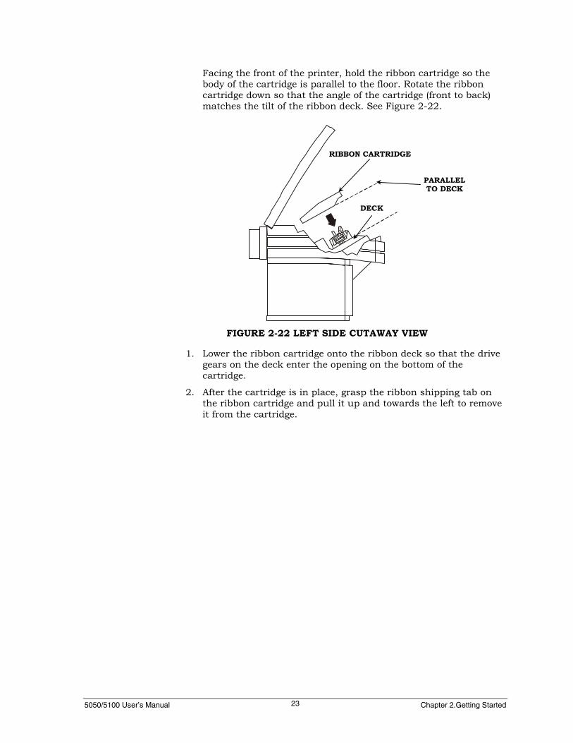
Facing the front of the printer, hold the ribbon cartridge so thebody of the cartridge is parallel to the floor. Rotate the ribboncartridge down so that the angle of the cartridge (front to back)matches the tilt of the ribbon deck. See Figure 2-22.
1. Lower the ribbon cartridge onto the ribbon deck so that the drivegears on the deck enter the opening on the bottom of thecartridge.
2. After the cartridge is in place, grasp the ribbon shipping tab onthe ribbon cartridge and pull it up and towards the left to removeit from the cartridge.
FIGURE 2-22 LEFT SIDE CUTAWAY VIEW
RIBBON CARTRIDGE
PARALLELTO DECK
DECK
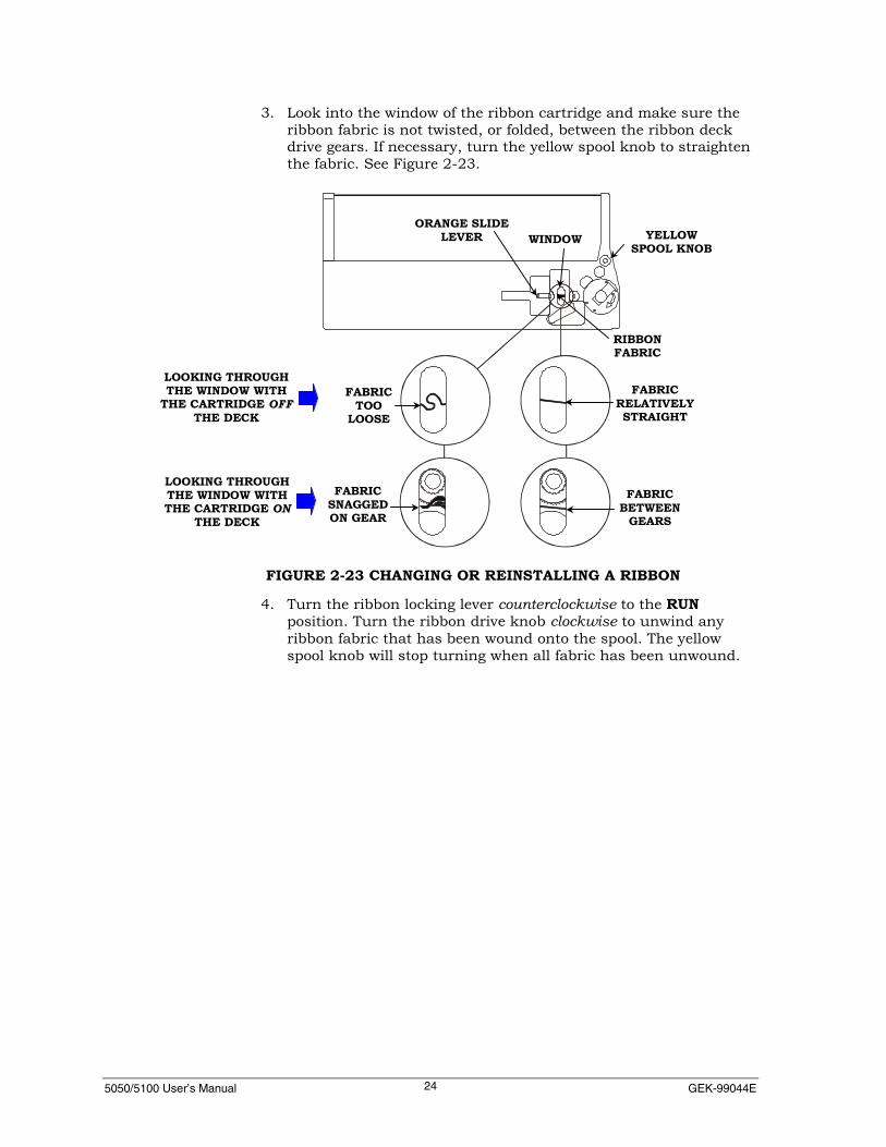
5050/5100 User’s Manual GEK-99044E24
3. Look into the window of the ribbon cartridge and make sure theribbon fabric is not twisted, or folded, between the ribbon deckdrive gears. If necessary, turn the yellow spool knob to straightenthe fabric. See Figure 2-23.
4. Turn the ribbon locking lever counterclockwise to the RUNposition. Turn the ribbon drive knob clockwise to unwind anyribbon fabric that has been wound onto the spool. The yellowspool knob will stop turning when all fabric has been unwound.
FIGURE 2-23 CHANGING OR REINSTALLING A RIBBON
ORANGE SLIDELEVER WINDOW YELLOW
SPOOL KNOB
RIBBONFABRIC
FABRICRELATIVELYSTRAIGHT
FABRICTOO
LOOSE
FABRICBETWEEN
GEARS
FABRICSNAGGEDON GEAR
LOOKING THROUGHTHE WINDOW WITH
THE CARTRIDGE OFFTHE DECK
LOOKING THROUGHTHE WINDOW WITHTHE CARTRIDGE ON
THE DECK

5050/5100 User’s Manual Chapter 2.Getting Started25
5. If the ribbon cartridge has a reinker, turn the reinker leverclockwise to the ON position. If necessary, see Figure 2-21.
NoteAfter the ribbon cartridge has been installed, the print gap, papertension, paper path, and top of form position must be set. See“Setting the Print Gap” later in this chapter for moreinformation.
Removing a Ribbon1. Place the printer offline and raise the top cover.
2. Turn the print gap wheel to the LOAD position. If necessary, seeFigure 2-14
3. Turn the ribbon locking lever clockwise to the LOAD position. Ifnecessary, see Figure 2-24.
4. Lift the ribbon off the ribbon deck.
FIGURE 2-24 RIBBON LOCKING
RIBBON LOCKINGLEVER IN RUN POSITION
RUNLOAD
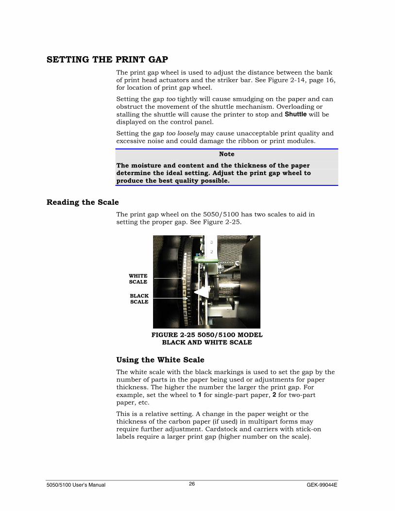
5050/5100 User’s Manual GEK-99044E26
SETTING THE PRINT GAPThe print gap wheel is used to adjust the distance between the bankof print head actuators and the striker bar. See Figure 2-14, page 16,for location of print gap wheel.
Setting the gap too tightly will cause smudging on the paper and canobstruct the movement of the shuttle mechanism. Overloading orstalling the shuttle will cause the printer to stop and Shuttle will bedisplayed on the control panel.
Setting the gap too loosely may cause unacceptable print quality andexcessive noise and could damage the ribbon or print modules.
NoteThe moisture and content and the thickness of the paperdetermine the ideal setting. Adjust the print gap wheel toproduce the best quality possible.
Reading the ScaleThe print gap wheel on the 5050/5100 has two scales to aid insetting the proper gap. See Figure 2-25.
Using the White ScaleThe white scale with the black markings is used to set the gap by thenumber of parts in the paper being used or adjustments for paperthickness. The higher the number the larger the print gap. Forexample, set the wheel to 1 for single-part paper, 2 for two-partpaper, etc.
This is a relative setting. A change in the paper weight or thethickness of the carbon paper (if used) in multipart forms mayrequire further adjustment. Cardstock and carriers with stick-onlabels require a larger print gap (higher number on the scale).
WHITESCALE
BLACKSCALE
FIGURE 2-25 5050/5100 MODELBLACK AND WHITE SCALE

5050/5100 User’s Manual Chapter 2.Getting Started27
Using the Black ScaleThe black scale with the white markings is used when directmeasurements in thousandths of an inch are made. Its main use wasduring the factory setup of the printer.
After the ideal gap setting has been found for a particular type ofform, note the wheel setting using the black scale. For example, afour-part form with a heavy first sheet may run best with the wheelset at 21 or 23 on the black scale instead of somewhere in the 4 rangeon the white scale. The smaller increments (one click of the wheel pernumber) provide a more accurate setting to go back to after reloadingpaper or changing the ribbon.
PAPER TENSION ADJUSTMENTThe paper tension lever is located next to the print gap wheel. It isused to maintain the proper tension on the paper during printing.See Figure 2-26.
Move the lever to position 1 (the bottom position) when loading paper,setting top of form, and printing single-part paper. This positionapplies the least tension to the paper and should be used as the firsttrial position for all forms.
For multipart forms and single-part paper that is heavier than 20pounds, higher paper tension lever settings may be required. Six-partforms are normally run at the second or third position.
The higher paper tension settings are used to squeeze air out frombetween the layers of multipart forms. Increase the tension if the printquality on the last part of the form is printing too light.
Note
Too much tension may tear the paper or elongate the holes.
FIGURE 2–26 PAPER TENSION LEVER5050/5100 MODEL
PAPER TENSIONLEVER
TENSION
HIGHER
LOWER
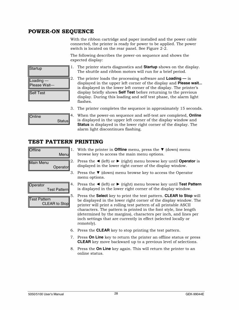
5050/5100 User’s Manual GEK-99044E28
POWER-ON SEQUENCEWith the ribbon cartridge and paper installed and the power cableconnected, the printer is ready for power to be applied. The powerswitch is located on the rear panel. See Figure 2-2.
The following describes the power-on sequence and shows theexpected display:
1. The printer starts diagnostics and Startup shows on the display.The shuttle and ribbon motors will run for a brief period.
2. The printer loads the processing software and Loading --- isdisplayed in the upper left corner of the display and Please wait...is displayed in the lower left corner of the display. The printer’sdisplay briefly shows Self Test before returning to the previousdisplay. During this loading and self test phase, the alarm lightflashes.
3. The printer completes the sequence in approximately 15 seconds.
4. When the power-on sequence and self-test are completed, Onlineis displayed in the upper left corner of the display window andStatus is displayed in the lower right corner of the display. Thealarm light discontinues flashing.
TEST PATTERN PRINTING1. With the printer in Offline menu, press the ▼ (down) menu
browse key to access the main menu options.
2. Press the ◄ (left) or ► (right) menu browse key until Operator isdisplayed in the lower right corner of the display window.
3. Press the ▼ (down) menu browse key to access the Operatormenu options.
4. Press the ◄ (left) or ► (right) menu browse key until Test Patternis displayed in the lower right corner of the display window.
5. Press the Select key to print the test pattern. CLEAR to Stop willbe displayed in the lower right corner of the display window. Theprinter will print a rolling test pattern of all printable ASCIIcharacters. The pattern is printed in the font style, line length(determined by the margins), characters per inch, and lines perinch settings that are currently in effect (selected locally orremotely).
6. Press the CLEAR key to stop printing the test pattern.
7. Press On Line key to return the printer an offline status or pressCLEAR key move backward up to a previous level of selections.
8. Press the On Line key again. This will return the printer to anonline status.
Startup
Loading ---Please Wait---
Self Test
OnlineStatus
OfflineMenu
Main MenuOperator
OperatorTest Pattern
Test PatternCLEAR to Stop

5050/5100 User’s Manual Chapter 2.Getting Started29
If printing becomes lighter gradually over a period of time, the ribbonmay need replacing.
Sample Test Pattern

5050/5100 User’s Manual GEK-99044E30
CHAPTER 3. OPERATING THE PRINTER
PRINTER OPERATIONAL MODESONLINE
OFFLINE
Fault State
Menu
Each printer state (mode) will display its own operationalcharacteristics. These modes are defined as follows:
OnlineThe online state is the normal operating mode of the printer where itis ready to accept data from the host. There are functionalrestrictions in this mode, to prevent interference with a print job thatmay be in progress.
OfflineThe offline state allows more operations including menu functions.
FaultThe fault state is a special case where a few options are available asthe machine is in a condition that will only allow operations that arerequired to clear the fault condition(s). The normal exit from the faultmode, after a fault is corrected, is to press the Clear key.
MenuThe menu state is where the settings or configuration of the printermay be altered.
Status DisplayDepressing the Select key while online activates the status display.The LCD cycles through and displays the current printer settings,including Format, Font Style, Code Page, CPI, Interface, PrinterEmulation and I/F Emulation. Press the Clear key to terminate thisdisplay.
5050/5100 User’s Manual Chapter 3. Operating the Printer31
MAIN MENUThe Main menu is organized in a tree structure. The active level isdisplayed on the upper left corner of the LCD display and selectionoptions available displayed sequentially one at a time, on the lowerright corner of the LCD display.
The Main menu presents only the allowable (not hidden) top levelselections, Operator menu, Setup menu, Maintenance menu andMenu Control. Only those menus selected will be displayed (See“Menu Control”, for further information.) The following menus areavailable from the Main menu level, if all menus are setup asaccessible:
▪ Operator menu
▪ Setup menu
▪ Maintenance menu
▪ Menu Control (See “Menu Control” on page 32 for procedures toview this menu.)
Operator MenuThe Operator menu is for the user to make certain selections.Normally, the Operator menu involves loading paper, correctingfaults, and allows temporary changes to settings that have previouslybeen set in the Setup menu. For procedures to navigate the operatormenu, see Chapter 4. For a complete listing of menu selections, seeOperator Menu Map in Appendix I.
Setup MenuThe Setup menu is used to setup the printer to the customer’senvironment as necessary for day to day normal operations. TheSetup menu allows configuration settings in the printer to bechanged and saved. Some settings are selected, enabled or user set.For procedures to navigate the setup menu, see Chapter 5. For acomplete listing of menu selections, see Setup Menu Map inAppendix I.
Maintenance MenuThe Maintenance menu is for the maintenance technician for tune-upoperations such as print actuator monitoring, and upgradeprocedures. The Maintenance menu contains selections for hardwaresetup, such as checking and resetting of counters, etc. Forprocedures on navigating the maintenance menu, see Chapter 6. Fora complete listing of menu selections, see Maintenance Menu Map inAppendix I.
MainOperator

5050/5100 User’s Manual GEK-99044E32
Menu ControlThe Menu control feature restricts/allows access to the other menus;Operator, Setup and Maintenance. This feature also restricts/allowsaccess to control panel keys: TearOff, view, and Format. This menu isonly visible after using the following procedure during power up:
▪ Simultaneously depress the FF key and the ↑ key while turningthe power on to the printer.
The printer will power up as normal, but a fourth menu, MenuControl, will be viewable and accessible.
SETTING UP A FORMATA format is a set of stored printer parameters tailored to a particularcustomer’s job, such as invoices, pick tickets, etc. and consists ofsetting a format name, font style, character set, country, CPI, LPI,form length, left margin, right margin, top print reference, left printreference, horizontal expansion, vertical expansion, print modifiers,print options, print control, general printer options, and the slewrate. The customer may set up to 10 different formats.
Setting up a format consists of two steps; modifying and saving aformat.
NoteUp to ten stored formats may be saved for later recall. Eachformat should be given a unique name.
Active FormatThe active format is a set of parameters that presently resides in theprinter’s processor. When printing starts, these active parameters areused to format the page.
The active format can be parameters that were entered through thecontrol panel, sent from the host, or one of the stored formatsselected. The active format is labeled ACTIVE on the status pageprintout.

5050/5100 User’s Manual Chapter 3. Operating the Printer33
Setting up the Active FormatThe active format can be set up using the following two methods:
▪ From the Setup menu, under Modify Format menu, the FormLength, Top Print Ref, etc may be set.
▪ ANSI Emulation - use the ESC[p1;p2;p3r escape sequence to setthe active form length, top print ref, etc. (See the Programmer’sManual for information on escape sequences.)
Note
See “Formats” for additional information.
Form LengthForm length is set using the current LPI (lines per inch) value. If theform length is set to 66 lines while the LPI is set at 6, the length willbe 11 inches. After the form length has been set up, a LPI change willnot change the form length. This is useful for matching odd sizeforms and Lines Per Inch settings. For example, 3-1/3 inch formlength and 8 LPI print spacing.
The minimum form length is .33 inch (2 lines at 6 LPI) and themaximum length is 22 inches (132 lines at 6 LPI).
Top Print RefSetting a Top Print Ref (top print reference) changes the effective firstprint position relative to the perforation. Setting a top print refeffectively changes the physical Top of Form paper position and is aone time physical offset of the paper that is executed at the Set TOFfunction. The top print ref (top print reference) is set using thecurrently set LPI value. If the offset distance is set to 6 lines while theLPI is set to 6, printing will start on line 7. Lines 1- 6 (1 inch) will beskipped. After the form has been set up, a LPI change will not alterthe length of the offset distance.

5050/5100 User’s Manual GEK-99044E34
LOW PAPER PRINTINGLow paper printing allows replenishing the forms supply withoutlosing data or forms registration.
This printer will print to the end of the current form or to the end ofthe last form (end of paper) after sensing a low paper condition if theform length corresponds with the active page length.
NoteIf the print job has been using reverse paper moves (backingpaper up while using bar codes, oversize, or vertical moves, donot use the low paper printing feature. Once the paper runs outof the lower tractors, poor print quality and jams will occur. Aform length of 12.5 inches or longer causes the printer to bypassthe low paper fault. The printer will go to a paper out condition.
Low PaperWhen the paper supply runs down to approximately 12.5 inches(32cm) remaining, the paper out sensor is activated. The alarm lightwill flash and Paper Almost Out will display in the upper left corner ofthe display.
1. Press the Clear key. Offline and Low Paper will be displayed inthe upper line of the display window and Menu will be displayedin the lower line of the display window.
2. Press the On Line key and the printer will finish the remainder ofthe current form and stop. Offline and Low Paper will bedisplayed in the upper line of the display window and Status willbe displayed in the lower line of the display. The printer will finishthe remainder of the current form and stop.
3. The alarm light will flash and Paper Out will display in the upperline of the display.
4. Replenish the paper supply in the printer. (See “ReplenishingPaper Supply for additional information.) The printer will finishthe job inside the printer buffer when the printer is replenishedwith paper and back online with the appropriate form settings.(See “Setting TOF” for additional information.)
Paper Almost Out
OfflineLow Paper
Offline Low PaperStatus
Paper Out
5050/5100 User’s Manual Chapter 3. Operating the Printer35
Replenishing Paper SupplyIf the operator wants to change forms or paper:
1. With the printer in the online status, press the FF (form feed) keyto eject the remaining forms out of the upper tractors. (If PaperOut is displayed in the upper left corner of the display window,press FF (form feed) key to eject the remaining form out of theupper tractors).
2. Load a fresh supply of paper/forms and return the print gapwheel to the proper setting. See “Loading Paper” in Chapter 1.
3. Use the ↑and/or ↓ arrow keys to make final adjustments to theperforation’s position relative to the center marks on the uppertractors.
4. Press TOF key and place the printer Online. (If necessary, seeSetting Top of Form below.)
5. Press the Clear key to clear the fault displays.
6. Press the On Line key to place the printer online.
OnlineStatus
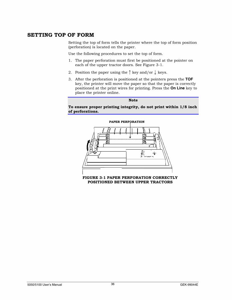
5050/5100 User’s Manual GEK-99044E36
SETTING TOP OF FORMSetting the top of form tells the printer where the top of form position(perforation) is located on the paper.
Use the following procedures to set the top of form.
1. The paper perforation must first be positioned at the pointer oneach of the upper tractor doors. See Figure 3-1.
2. Position the paper using the ↑ key and/or ↓ keys.
3. After the perforation is positioned at the pointers press the TOFkey, the printer will move the paper so that the paper is correctlypositioned at the print wires for printing. Press the On Line key toplace the printer online.
NoteTo ensure proper printing integrity, do not print within 1/8 inchof perforations.
FIGURE 3-1 PAPER PERFORATION CORRECTLYPOSITIONED BETWEEN UPPER TRACTORS
PAPER PERFORATION

5050/5100 User’s Manual Chapter 3. Operating the Printer37
PAPER TEAR-OFF FEATUREPressing the Tear Off key starts the paper tear-off feature cycle. (Alsosee Tear Off menu option on page 133 for additional information.
This feature moves the paper forward far enough to tear off the lastprinted form at its perforation. Tearoff will show in the display. Aftera 15-second delay, the beeper will sound a warning and the paperwill retract back into the printer and be positioned ready to print.
Pressing the Tear Off key a second time during this cycle will cancelthe 15-second delay and immediately retract the paper.
This feature will not work during a fault condition such as RibbonJam or Strikr Bar Open.
Paper Path (55 or 60 dBa Cabinet Model Only)The distance the forms are ejected and retracted depends on whichpaper path (top exit or rear exit) is being used. (See TearOff menuoption in chapter 5.)
LOCAL AUTO VIEW FEATUREThe local auto view feature is used to view the last line printedthrough the glass in the top cover.
ViewingThis feature is activated using the View key from the control panel.Pressing the View key causes the paper to move up until the lastprinted line is at the pointers of the upper tractors.
RetractingPressing the View key a second time will cause the paper to moveback down until it is positioned at the print wires ready for printing.Receipt of any data will also retract the paper to the print position.

5050/5100 User’s Manual GEK-99044E38
THE INTERLOCK CIRCUITThis printer has an interlock circuit to meet safety and internationalrequirements.
The interlock switch circuit disables the power supply voltage whenthe ribbon deck is lifted. This eliminates any potential shock hazardor inadvertant printer start-up while moving parts in the print areaare accessible. The ribbon deck must be in place and all threethumbscrews must be tightened securely for printer operation. SeeFigure 2-27.
NoteRemoving the ribbon deck with the power applied will energizethe interlock circuit. If this happens, the deck must be replaced,power must be turned off for a period of 5 minutes beforeattempting to reapply power.
INITIALIZING THE PRINTERInitializing resets the printer electronics and sets the printerparameters to factory defaults. Parameters include margins, tabs,forms control, characters per inch, lines per inch, etc.
When to InitializeInitialize the printer when:
▪ It is desirable to reset the printer to the factory default settings.
▪ After new software has been installed.
▪ Repair actions involving the logic circuit boards have been made.
THREETHUMBSCREWS
FIGURE 2-27THUMBSCREWS ON RIBBON DECK

5050/5100 User’s Manual Chapter 3. Operating the Printer39
USING THE KEYPAD TO INITIALIZEUsing the control panel keys to initialize the printer allows resettingto the factory default parameters, all interfaces, all emulations, allformats or a complete reset of all parameters.
If the printer was operating before initialization, it may need to bereconfigured for the specific task at hand. Refer to the status pageprintout and/or formats page printout to reset the printers settingsto those used before initialization. (See “Show” in the “Using theOperator’s Menu” section of Chapter 4 for procedures to print thestatus page and formats page.)
NoteThe menu options All Formats, All Interfaces, and All Emulations willreset all previously saved settings (customer defined) to factorydefaults. Previously saved formats, interface settings andemulation options cannot be recalled. It is recommended that astatus page and format page be printed before performing thisoption. Use these printouts to re-configure formats, settings,and/or options after resetting to factory defaults.

5050/5100 User’s Manual GEK-99044E40
Control Panel InitializationUse the following procedures to initialize the printer using the controlpanel:
NoteIf the printer has locked up and the keys on the control panel donot respond, it may be necessary to cycle the power on theprinter. Turn the printer off, wait 2-3 minutes, and power theprinter back on.
1. Press the On Line key to place the printer in an offline state.
2. Press the ▼ (down) menu browse key to access the Main Menu.
3. Press the ◄ (left) or ► (right) menu browse key until Maintenanceis displayed in the lower right corner of the display window.
4. Press the ▼ (down) arrow to access the Maintenance menuoptions. Maintenance will be displayed in the upper left corner ofthe display window and Reset to Deflts will be displayed in thelower right corner.
5. Press the ▼ (down) menu browse key again. USA will be displayedin the lower right corner of the display window.
6. Press the ◄ (left) or ► (right) menu browse key to select a USA orInternational setting.
7. Press the ▼ (down) menu browse to access the options underUSA or International.
8. Press the ◄ (left) or ► (right) menu browse key to select either, AllInterfaces, All Formats, All Emulations, or Complete.
9. Press the Select key next to the type of reset option desired toreset printer. The printer momentarily displays STARTUP,Loading..... Please Wait then completes the power-up sequence.
NoteThe All Interfaces option will reset all interface settings in theprinter to the factory set default values or settings. The AllFormats option will reset all previously saved formats in theprinter to the factory set default values or settings. The AllEmulations option will reset all emulation settings in the printerto factory set default values or settings. The Complete optionwill reset the printer to factory set defaults for all interfaces, allpreviously saved formats, and all emulations.
OfflineMenu
Main MenuMaintenance
MaintenanceReset to Deflts
Reset to DefltsUSA
Factory DefltsAll Interfaces
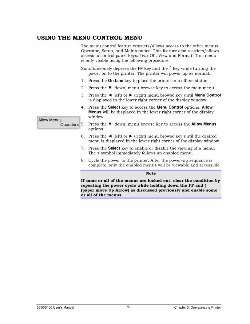
5050/5100 User’s Manual Chapter 3. Operating the Printer41
USING THE MENU CONTROL MENUThe menu control feature restricts/allows access to the other menus:Operator, Setup, and Maintenance. This feature also restricts/allowsaccess to control panel keys: Tear Off, View and Format. This menuis only visible using the following procedure:
Simultaneously depress the FF key and the ↑ key while turning thepower on to the printer. The printer will power up as normal.
1. Press the On Line key to place the printer in a offline status.
2. Press the ▼ (down) menu browse key to access the main menu.
3. Press the ◄ (left) or ► (right) menu browse key until Menu Controlis displayed in the lower right corner of the display window.
4. Press the Select key to access the Menu Control options. AllowMenus will be displayed in the lower right corner of the displaywindow.
5. Press the ▼ (down) menu browse key to access the Allow Menusoptions.
6. Press the ◄ (left) or ► (right) menu browse key until the desiredmenu is displayed in the lower right corner of the display window.
7. Press the Select key to enable or disable the viewing of a menu.The < symbol immediately follows an enabled menu.
8. Cycle the power to the printer. After the power-up sequence iscomplete, only the enabled menus will be viewable and accessible.
NoteIf some or all of the menus are locked out, clear the condition byrepeating the power cycle while holding down the FF and ↑(paper move Up Arrow) as discussed previously and enable someor all of the menus.
Allow MenusOperator<
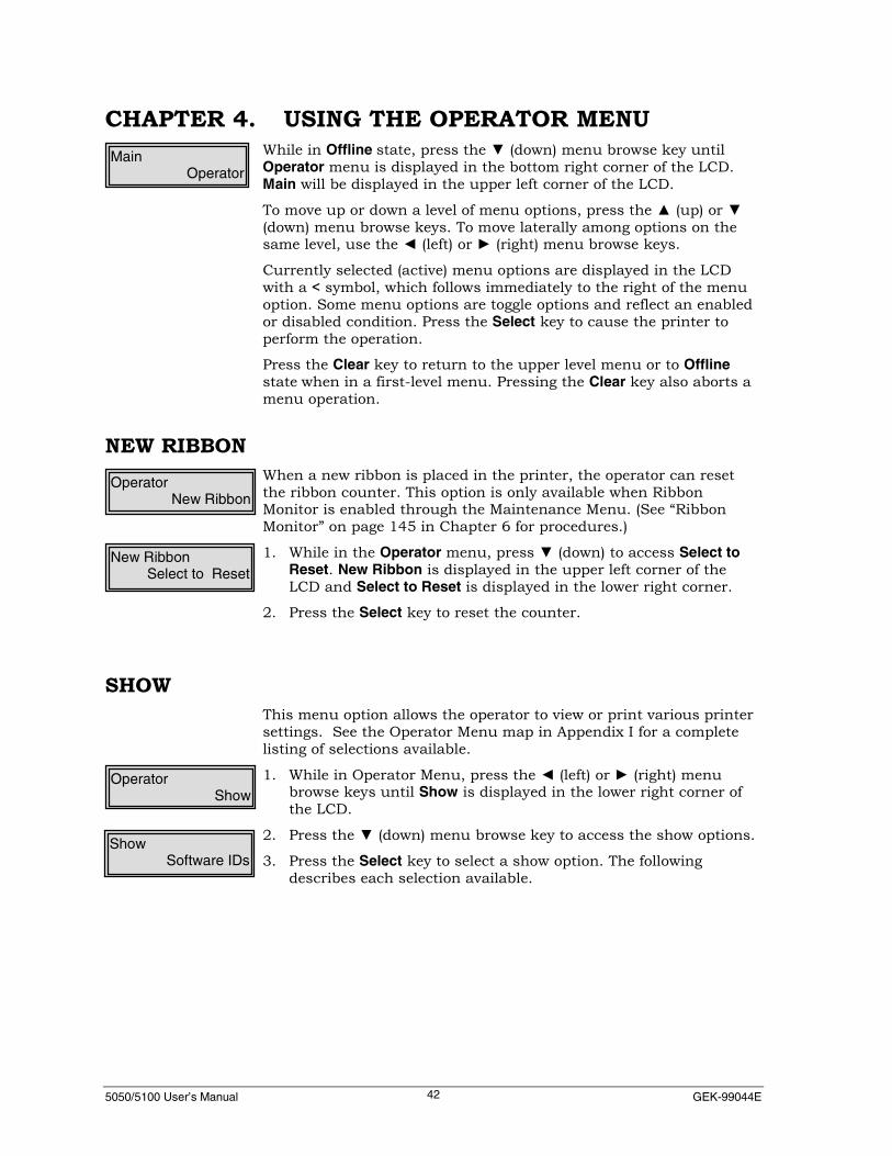
5050/5100 User’s Manual GEK-99044E42
CHAPTER 4. USING THE OPERATOR MENUWhile in Offline state, press the ▼ (down) menu browse key untilOperator menu is displayed in the bottom right corner of the LCD.Main will be displayed in the upper left corner of the LCD.
To move up or down a level of menu options, press the ▲ (up) or ▼(down) menu browse keys. To move laterally among options on thesame level, use the ◄ (left) or ► (right) menu browse keys.
Currently selected (active) menu options are displayed in the LCDwith a < symbol, which follows immediately to the right of the menuoption. Some menu options are toggle options and reflect an enabledor disabled condition. Press the Select key to cause the printer toperform the operation.
Press the Clear key to return to the upper level menu or to Offlinestate when in a first-level menu. Pressing the Clear key also aborts amenu operation.
NEW RIBBONWhen a new ribbon is placed in the printer, the operator can resetthe ribbon counter. This option is only available when RibbonMonitor is enabled through the Maintenance Menu. (See “RibbonMonitor” on page 145 in Chapter 6 for procedures.)
1. While in the Operator menu, press ▼ (down) to access Select toReset. New Ribbon is displayed in the upper left corner of theLCD and Select to Reset is displayed in the lower right corner.
2. Press the Select key to reset the counter.
SHOWThis menu option allows the operator to view or print various printersettings. See the Operator Menu map in Appendix I for a completelisting of selections available.
1. While in Operator Menu, press the ◄ (left) or ► (right) menubrowse keys until Show is displayed in the lower right corner ofthe LCD.
2. Press the ▼ (down) menu browse key to access the show options.
3. Press the Select key to select a show option. The followingdescribes each selection available.
MainOperator
OperatorNew Ribbon
New RibbonSelect to Reset
ShowSoftware IDs
OperatorShow

5050/5100 User’s Manual Chapter 4. Using the Operator Menu43
Software IDsThis option displays the part or version number of the installedsoftware. This is a view only option. When selected, the display willautomatically cycle and display information similar to the followingdisplay example:
TTMI: 44A106030Font: 44A100095CCU: 44A109005Panl: 44A119255XXXY: <Revision Number> *
* XXXY: are board identifiers, where XXX is the option boardinstalled, Y is the expansion slot number and <Revision Number> isadditional information (i.e. part number if applicable.)
Expansion Slot InformationOption Board Installed Board IdentifierLegacy Parallel (Centronics, DP Short, DP Long) Leg1: or Leg2:Ethernet (any speed) or Token Ring Net1: or Net2:empty or unknown board Exp1: or Exp2:IBM front end board Fep1: or Fep2:
Sample Status PageSelecting this option will print the current settings of the printer.Press the Clear key to stop printing. The following two pages, are asample printout of the status page, reflecting the factory defaultsettings with standard software installed.

5050/5100 User’s Manual GEK-99044E44
Status Page 5100Operator
Software IDsTTMI: 44A106030 (13.X”)Font: 44A100095CCU: 44A109005Panl: 44A119255Exp1: (empty)Exp2: (empty)
Set UpActive Format
Format Name DEFAULTFont Style Data ProcesCharSet/Country USA CP 437 USA ISOCPI 10LPI 6
By IN By Line/Column By DecipointForm Length 11.00 66 7920Top Margin 00.00 0 0Bottom Margin 00.00 0 0Left Margin 00.00 0 0Right Margin 13.60 136 9792Top Print Ref 00.00 0 0Left Print Ref 00.00 0 0Horiz Expansion X1Vert Expansion X1VertExp Options Default (top)Print Modifiers
DoubleStrike DisableEmphasized Disable
Print OptionsUpperCase DisableHigh Speed Enable
Print ControlDefine LF LF = CR + LFDefine CR CR = CRDefine FF FF = CR + FFDefine HT NoTabs = SPACEVertMove VM = CR + VMAutoWrap EnableFF @ TOF Enable
GenPtrOpts0 1 2 312345678901234567890123456789012
Group 1 01100001000100000000000000000000Group 2 00010011001110000000000000000000
Slew Rate NormalInterface MultiSourceEmulation ANSI (4800)Filter
Parallel (1284)None
SerialNone
Expansion1None
Expansion2None
Horiz Tab00.80” 01.60” 02.40” 03.20” 04.00” 04.80”05.60” 06.40” 07.20” 08.00” 08.80” 09.60”10.40” 11.20” 12.00” 12.80”
Vertical Format Vertical TabsVert Tab
None

5050/5100 User’s Manual Chapter 4. Using the Operator Menu45
IF SettingsMultiSource Delay Seconds 003Parallel Setup (1284)
No Fault PO DisableTCP/IP
IP Address 000.000.000.000Netmask 000.000.000.000Router IP Addr 000.000.000.000
Serial Setup RS232XON/XOFF
Ready/Busy EnableON/OFFline EnableFault EnableRobust XOFF DisableRobust XON Disable
CD(DTR)Ready/Busy DisableON/OFFline DisableFault Disable
CA(RTS)Ready/Busy DisableON/OFFline DisableFault Disable
SCA(SRTS)Ready/Busy DisableON/OFFline DisableFault Disable
ETX/ACK DisableInhibit Xmit DisableLead Polarity
CD(DTR) HighCA(RTS) HighSCA(SRTS) HighCB(CTS) HighCC(DSR) High
Data Bits 8 BitsParity No Parity BitStop Bits 1Baud Rate 9600Buffer Options High Trip Pt % 80
Expansion1None
Expansion2None
Engine OptionsDirection Bi-directionalEngineOff Delay 2 secondsPrint Intensity Normal
TearOff OptionsPath TopRetract Next TOF
Emul Settings ANSI (4800)0 1 2 312345678901234567890123456789012
Options 00000010010000000000000000000000Filter Settings
NoneMaintenance
Power On Time 00000:00:00Print Time 00000:00:00Memory Usage
RAM Size 4096 kBCode Size 2270 kBHeap Used 727 kBFree Mem 695 kB
RibbonMonitor Disable

5050/5100 User’s Manual GEK-99044E46
Sample Format PageSelecting this option will print a description of optional pre-savedformat (also known as a form.) Press the Clear key to stop printing.
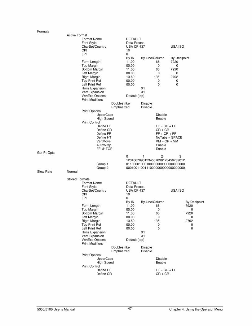
5050/5100 User’s Manual Chapter 4. Using the Operator Menu47
FormatsActive Format
Format Name DEFAULTFont Style Data ProcesCharSet/Country USA CP 437 USA ISOCPI 10LPI 6
By IN By Line/Column By DecipointForm Length 11.00 66 7920Top Margin 00.00 0 0Bottom Margin 11.00 66 7920Left Margin 00.00 0 0Right Margin 13.60 136 9792Top Print Ref 00.00 0 0Left Print Ref 00.00 0 0Horiz Expansion X1Vert Expansion X1VertExp Options Default (top)Print Modifiers
Doublestrike DisableEmphasized Disable
Print OptionsUpperCase DisableHigh Speed Enable
Print ControlDefine LF LF = CR + LFDefine CR CR + CRDefine FF FF + CR + FFDefine HT NoTabs = SPACEVertMove VM = CR + VMAutoWrap EnableFF @ TOF Enable
GenPtrOpts0 1 2 312345678901234567890123456789012
Group 1 01100001000100000000000000000000Group 2 00010011001110000000000000000000
Slew Rate Normal
Stored FormatsFormat Name DEFAULTFont Style Data ProcesCharSet/Country USA CP 437 USA ISOCPI 10LPI 6
By IN By Line/Column By DecipointForm Length 11.00 66 7920Top Margin 00.00 0 0Bottom Margin 11.00 66 7920Left Margin 00.00 0 0Right Margin 13.60 136 9792Top Print Ref 00.00 0 0Left Print Ref 00.00 0 0Horiz Expansion X1Vert Expansion X1VertExp Options Default (top)Print Modifiers
Doublestrike DisableEmphasized Disable
Print OptionsUpperCase DisableHigh Speed Enable
Print ControlDefine LF LF = CR + LFDefine CR CR + CR

5050/5100 User’s Manual GEK-99044E48
Sample Code PageSelecting this option will print an example of thecurrently selected code page/country charactertable. Press the Clear key to stop printing. SeeFigure 4-1.
Sample Font PageSelecting this option prints the current font package included in theprinter software. The Font Page printout is meant to compliment theStatus Page printout. This report is for reference purposes only, itreflects the fonts included in the Font part number, which isidentified under Software IDs on the Status Page printout. It does notreflect selections or settings, either default or customer-defined. Pressthe Clear key to stop printing. The following is an example of the fontpage printout.
FIGURE 4-1 SAMPLE CODE PAGE

5050/5100 User’s Manual Chapter 4. Using the Operator Menu49
Font Page 5050Font Package: 44A100082Font List Alignment ALN:10 66
Courier NLQ CON:10 1000CON:13 1000
Correspond CRE:10 1000CRE:13 1000
Data Proces GCD:10 1000GCD:13 1000GCD:16 1000
Gothic NLQ GCN:10 1000GCN:13 1000GCN:16 1000
High Speed 2 HSD:10 1000High Speed THD:10 1000
HSD:16 1000Italic NLQ ITN:10 1000Graphics LGD:10 1000
LGD:13 1000LGD:16 1000
OCR-A OAN:10 1000OCR-B OBN:10 1000CanadianPst ORN:16 1000
Number of Maps: 130
Maps (Overlay):USA ISO Germany French A ISO French B ISO CanadianDutch Italian UK ISO Spanish Dan/Nor ADan/Nor B Dan/Nor C Dan/Nor D Swed/Fin A Swed/Fin BSwed/Fin C Swed/Fin D Swiss Slo/Croat UK ATurkish Greek Italian ISO Spanish ISO FX: USAFX: France FX: Germany FX: UK FX: Denmark I FX: Denmark IIFX: Italy FX: Spain I FX: Japan FX: Norway FX: Denmark IIFX: Spain II FX: Latin Amer FX: Netherland FX: Angl-Unvrs FX: SpanAmerFX: Portugal FX: Africa FX: Switzerland FX: Turkey FX: GreeceFX: Slo/Croat Legal Korea None Download Map
Maps (Code Page):RevQuest USA CP 437 Multi CP 850 Code Page 852 Code Page 853Code Page 855 Code Page 858 Code Page 860 Code Page 863 Code Page 864Code Page 865 Code Page 866 Code Page 867 Greek CP 437 Dec MultiNtnlRoman 8 Mazowia CP Turkish CP Greek CP 851 KamenISO-8859-1 ISO-8859-2 ISO-8859-3 ISO-8859-4 ISO-8859-5ISO-8859-6 ISO-8859-7 ISO-8859-8 ISO-8859-9 ISO-8859-15Code Page 864E Greek CP869 ELOT 928 Dec Supp Dec TechDec Spec1Graph Dec ISO-Latin 1 Dec British Dec Finnish Dec FrenchDec FrCanadian Dec German Dec ISO Italian Dec JIS Roman Dec Nor/DanDec Spanish Dec Swedish Dec ISO Nor/Dan Dec Dutch Dec SwissDec Portuguese Dec Legal Dec Hebrew Dec Hebrew Supp Dec ISO Lat/HebDec Katakana Dec ANSI ISO Latin 2 ISO Latin 5 Greek SuppTurkish 7-Bit Turkish 8-Bit ISO/Lat/Gr Supp ISO Lat/Cy Supp PC437 GreekPC861 Icelandic PC869 Greek USSR (GOST) BRASCII ABICOMPPC857 (Turkish) ISO Latin 1T Bulgaria Code MJK (CSFR) EstoniaPC774 Lithuania PC866 LAT ECMA-94-1 Mult KU 42(KU Thai) TIS 11(TS 988)TIS 13 (IBM Std) TIS 16 (SIC Old) TIS 17 (SIC STD) TIS 18 (General) HP3000 GreekDEC Greek Farsi A Farsi B Farsi C

5050/5100 User’s Manual GEK-99044E50
TEST PATTERNSelecting this option will print a test pattern until the operatorpresses the Clear key to stop. This option can be used to verifyprinting occurs at the top of form. See “Test Pattern Printing” inChapter 2 for additional information.
DISCARD JOBThis menu option is used to clear the printer’s buffer.
1. While in the Operator menu, press the ◄ (left) or ► (right) menubrowse key until Discard Job is displayed in the lower right cornerof the LCD.
OperatorTest Pattern

5050/5100 User’s Manual Chapter 5. Using the Setup Menu51
CHAPTER 5. USING THE SET UP MENUThe Set Up menu allows the operator to modify or create storedformats. The Set Up menu also allows the operator to set defaultsettings for Horiz Tab, Vertical Format, Interface Settings, EngineOptions, Print Control, GenPtrOpts (General Printer Options),TearOff, Emulation, Display Lang (Display Language) and Filter. SeeAppendix I for the complete Set Up Menu Map.
While in the Offline state, press the ▼ (down) menu browse key untilSet Up menu is displayed in the bottom right corner of the LCD. MainMenu will be displayed in the upper left corner of the LCD.
To move up or down a level of menu options, press the ▲ (up) or ▼(down) menu browse keys. To move laterally among options on thesame level, use the ◄ (left) or ► (right) menu browse keys.
Currently selected menu options are displayed in the LCD with a <symbol, which follows immediately to the right of the menu option.Some menu options are toggle options and reflect an enabled ordisabled condition. Press the Select key to cause the printer toperform this operation.
Press the Clear key to return to the upper level menu or to Offlinewhen in a first-level menu.
FORMATThis menu option allows the operator to change or create and storeformat settings for the printer. (See Set Up menu map in Appendix Ifor available selections.
There are two steps to changing or creating a stored format.
1. Modify the format. (See “Modify Format” for procedures andmenu options.)
2. Save the format. (See “Save Format” for procedures and menuoptions.)
Main MenuSet Up

5050/5100 User’s Manual GEK-99044E52
Modify FormatThis menu option allows the operator to modify a format.
1. While in Format menu, press ◄ (left) or ► (right) until ModifyFormat is displayed in the lower right corner of the LCD.
2. Press the ▼ (down) menu browse key to access the Modify Formatoptions.
The following describes each of the selections available.
Format NameThis menu option allows the operator to change the selected formatname. The LCD will display the format selected from the controlpanel using the Format key. If no previously saved format nameexists, the format will be displayed as Default.
NoteUse unique format names when creating or modifying a format.
1. While in Modify Format menu, press the ◄ (left) or ► (right) menubrowse keys until Format Name is displayed in the lower rightcorner of the LCD.
2. Press the Select key to select a Format Name option. Notice thecursor (underline) beneath the currently selected character to bechanged.
3. In Format Name, the display switches to a mode where theoperator may enter any alphanumeric character. The four menubrowse keys revert to data entry operation. The horizontal ◄ ►(left or right) keys position the cursor (underline) to the digit to bechanged; the vertical ▲ ▼ (up or down) keysincrement/decrement the selected digit by one. Alphanumericcharacters will display in place of the underlined digitsequentially.
4. Press the Clear key after all changes are complete and thedesired value is displayed in the lower right corner of the LCD.Pressing the Clear key does not erase the values entered, but doesallow the user to exit the User Set menu.
NoteRepeat this section if further changes are necessary.
Modify FormatFormat Name
FormatModify Format
Modify FormatDefault
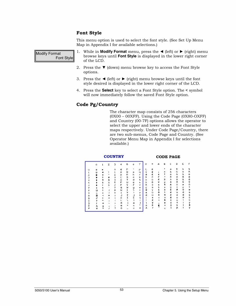
5050/5100 User’s Manual Chapter 5. Using the Setup Menu53
Font StyleThis menu option is used to select the font style. (See Set Up MenuMap in Appendix I for available selections.)
1. While in Modify Format menu, press the ◄ (left) or ► (right) menubrowse keys until Font Style is displayed in the lower right cornerof the LCD.
2. Press the ▼ (down) menu browse key to access the Font Styleoptions.
3. Press the ◄ (left) or ► (right) menu browse keys until the fontstyle desired is displayed in the lower right corner of the LCD.
4. Press the Select key to select a Font Style option. The < symbolwill now immediately follow the saved Font Style option.
Code Pg/CountryThe character map consists of 256 characters(0X00 – 00XFF). Using the Code Page (0X80-OXFF)and Country (00-7F) options allows the operator toselect the upper and lower ends of the charactermaps respectively. Under Code Page/Country, thereare two sub-menus, Code Page and Country. (SeeOperator Menu Map in Appendix I for selectionsavailable.)
Modify FormatFont Style
COUNTRY CODE PAGE
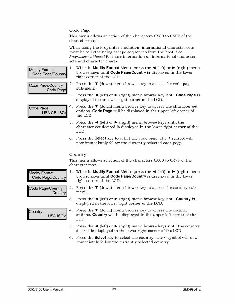
5050/5100 User’s Manual GEK-99044E54
Code PageThis menu allows selection of the characters 0X80 to 0XFF of thecharacter map.
When using the Proprinter emulation, international character setsmust be selected using escape sequences from the host. SeeProgrammer’s Manual for more information on international charactersets and character charts.
1. While in Modify Format Menu, press the ◄ (left) or ► (right) menubrowse keys until Code Page/Country is displayed in the lowerright corner of the LCD.
2. Press the ▼ (down) menu browse key to access the code pagesub-menu.
3. Press the ◄ (left) or ► (right) menu browse key until Code Page isdisplayed in the lower right corner of the LCD.
4. Press the ▼ (down) menu browse key to access the character setoptions. Code Page will be displayed in the upper left corner ofthe LCD.
5. Press the ◄ (left) or ► (right) menu browse keys until thecharacter set desired is displayed in the lower right corner of theLCD.
6. Press the Select key to select the code page. The < symbol willnow immediately follow the currently selected code page.
CountryThis menu allows selection of the characters 0X00 to 0X7F of thecharacter map.
1. While in Modify Format Menu, press the ◄ (left) or ► (right) menubrowse keys until Code Page/Country is displayed in the lowerright corner of the LCD.
2. Press the ▼ (down) menu browse key to access the country sub-menu.
3. Press the ◄ (left) or ► (right) menu browse key until Country isdisplayed in the lower right corner of the LCD.
4. Press the ▼ (down) menu browse key to access the countryoptions. Country will be displayed in the upper left corner of theLCD.
5. Press the ◄ (left) or ► (right) menu browse keys until the countrydesired is displayed in the lower right corner of the LCD.
6. Press the Select key to select the country. The < symbol will nowimmediately follow the currently selected country.
Modify FormatCode Page/Country
Code Page/CountryCode Page
Code PageUSA CP 437<
Code Page/CountryCountry
CountryUSA ISO<
Modify FormatCode Page/Country
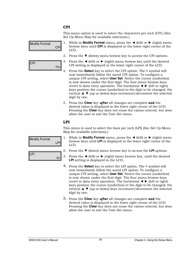
5050/5100 User’s Manual Chapter 5. Using the Setup Menu55
CPIThis menu option is used to select the characters per inch (CPI.) (SeeSet Up Menu Map for available selections.)
1. While in Modify Format menu, press the ◄ (left) or ► (right) menubrowse keys until CPI is displayed in the lower right corner of theLCD.
2. Press the ▼ (down) menu browse key to access the CPI options.
3. Press the ◄ (left) or ► (right) menu browse key until the desiredCPI setting is displayed in the lower right corner of the LCD.
4. Press the Select key to select the CPI option. The < symbol willnow immediately follow the saved CPI option. To configure aunique CPI setting, select User Set. Notice the cursor (underline)is now shown under the first digit. The four menu browse keysrevert to data entry operation. The horizontal ◄ ► (left or right)keys position the cursor (underline) to the digit to be changed; thevertical ▲ ▼ (up or down) keys increment/decrement the selecteddigit by one.
5. Press the Clear key after all changes are complete and thedesired value is displayed in the lower right corner of the LCD.Pressing the Clear key does not erase the values entered, but doesallow the user to exit the User Set menu.
LPIThis menu is used to select the lines per inch (LPI) (See Set Up MenuMap for available selections.)
1. While in Modify Format menu, press the ◄ (left) or ► (right) menubrowse keys until LPI is displayed in the lower right corner of theLCD.
2. Press the ▼ (down) menu browse key to access the LPI options.
3. Press the ◄ (left) or ► (right) menu browse key, until the desiredLPI setting is displayed in the LCD.
4. Press the Select key to select the LPI option. The < symbol willnow immediately follow the saved LPI option. To configure aunique CPI setting, select User Set. Notice the cursor (underline)is now shown under the first digit. The four menu browse keysrevert to data entry operation. The horizontal ◄ ► (left or right)keys position the cursor (underline) to the digit to be changed; thevertical ▲ ▼ (up or down) keys increment/decrement the selecteddigit by one.
5. Press the Clear key after all changes are complete and thedesired value is displayed in the lower right corner of the LCD.Pressing the Clear key does not erase the values entered, but doesallow the user to exit the User Set menu.
Modify FormatCPI
Modify FormatLPI
CPI10<
LPI6<

5050/5100 User’s Manual GEK-99044E56
Form LengthThis menu option is used to set the form length. The form length maybe set By Lines (6 LPI) or By Lines (8 LPI).
1. While in Modify Format menu, press the ◄ (left) or ► (right) menubrowse keys until Form Length is displayed in the lower rightcorner of the LCD.
2. Press the ▼ (down) menu browse key to access the Form Lengthoptions. Form Length will be displayed in upper left corner ofLCD.
3. Press ◄ (left) or ► (right) menu browse key and select By Lines (6LPI) or By Lines (8 LPI). Press the Select key to select one of theseoptions. The current setting is displayed in the lower right cornerof the LCD.
4. Press the Select key again to modify the setting. Notice the cursor(underline) is now shown under the first digit. The four menubrowse keys revert to data entry operation. The horizontal ◄ ►(left or right) keys position the cursor (underline) to the digit to bechanged; the vertical ▲ ▼ (up or down) keysincrement/decrement the selected digit by one.
5. Press the Clear key after all changes are complete and thedesired value is displayed in the lower right corner of the LCD.Pressing the Clear key does not erase the values entered, but doesallow the user to exit the User Set menu.
Note
Repeat this section if further changes are necessary.
Modify FormatForm Length
Form LengthBy Lines (6LPI)
Form Length006
Form Length006
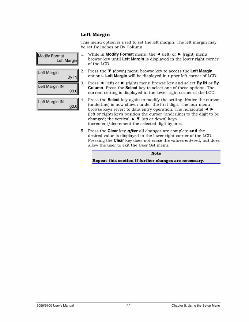
5050/5100 User’s Manual Chapter 5. Using the Setup Menu57
Left MarginThis menu option is used to set the left margin. The left margin maybe set By Inches or By Column.
1. While in Modify Format menu, the ◄ (left) or ► (right) menubrowse key until Left Margin is displayed in the lower right cornerof the LCD.
2. Press the ▼ (down) menu browse key to access the Left Marginoptions. Left Margin will be displayed in upper left corner of LCD.
3. Press ◄ (left) or ► (right) menu browse key and select By IN or ByColumn. Press the Select key to select one of these options. Thecurrent setting is displayed in the lower right corner of the LCD.
4. Press the Select key again to modify the setting. Notice the cursor(underline) is now shown under the first digit. The four menubrowse keys revert to data entry operation. The horizontal ◄ ►(left or right) keys position the cursor (underline) to the digit to bechanged; the vertical ▲ ▼ (up or down) keysincrement/decrement the selected digit by one.
5. Press the Clear key after all changes are complete and thedesired value is displayed in the lower right corner of the LCD.Pressing the Clear key does not erase the values entered, but doesallow the user to exit the User Set menu.
Note
Repeat this section if further changes are necessary.
Modify FormatLeft Margin
Left MarginBy IN
Left Margin IN00.0
Left Margin IN00.0

5050/5100 User’s Manual GEK-99044E58
Right MarginThis menu option is used to set the right margin. The right marginmay be set By Inches or By Column.
1. While in Modify Format menu, press the ◄ (left) or ► (right) menubrowse keys until Right Margin is displayed in the lower rightcorner of the LCD.
2. Press the ▼ (down) menu browse key to access the Right Marginoptions. Right Margin will be displayed in upper left corner ofLCD.
3. Press ◄ (left) or ► (right) menu browse key and select By IN or ByColumn. Press the Select key to select one of these options. Thecurrent setting is displayed in the lower right corner of the LCD.
4. Press the Select key again to modify the setting. Notice the cursor(underline) is now shown under the first digit. The four menubrowse keys revert to data entry operation. The horizontal ◄ ►(left or right) keys position the cursor (underline) to the digit to bechanged; the vertical ▲ ▼ (up or down) keysincrement/decrement the selected digit by one.
5. Press the Clear key after all changes are complete and thedesired value is displayed in the lower right corner of the LCD.Pressing the Clear key does not erase the values entered, but doesallow the user to exit the User Set menu.
Note
Repeat this section if further changes are necessary.
Modify FormatRight Margin
Right MarginBy IN
Right Margin IN00.0
Right Margin IN00.0

5050/5100 User’s Manual Chapter 5. Using the Setup Menu59
Top Print RefThis menu option is used to set the top print ref. The top print refmay be set By Inches.
1. While in Modify Format menu, press the ◄ (left) or ► (right)menu browse keys until Top Print Ref is displayed in the lowerright corner of the LCD.
2. Press the ▼ (down) menu browse key to access the Top Print Refoptions. Top Print Ref will be displayed in upper left corner ofLCD.
3. Press the Select key again to modify the setting. Notice the cursor(underline) is now shown under the first digit. The four menubrowse keys revert to data entry operation. The horizontal ◄ ►(left or right) keys position the cursor (underline) under the digitto be changed; the vertical ▲ ▼ (up or down) keysincrement/decrement the selected digit by one.
4. Press the Clear key after all changes are complete and thedesired value is displayed in the lower right corner of the LCD.Pressing the Clear key does not erase the values entered, but doesallow the user to exit the User Set menu.
NoteRepeat this section if further changes are necessary.
Modify FormatTop Print Ref
Top Print RefBy IN
Top Print Ref IN00.0

5050/5100 User’s Manual GEK-99044E60
Left Print RefThis menu option is used to set the left print ref. The left print refmay be set By Inches or By Column.
Use the following procedures for setting the left print ref:
1. While in Modify Format menu, press the ◄ (left) or ► (right) menubrowse keys until Left Print Ref is displayed in the lower rightcorner of the LCD.
2. Press the ▼ (down) menu browse key to access the Left Print Refoptions. Left Print Ref will be displayed in upper left corner ofLCD.
3. Press ◄ (left) or ► (right) menu browse key and select By IN or ByColumn. Press the Select key to select one of these options. Thecurrent setting is displayed in the lower right corner of the LCD.
4. Press the Select key again to modify the setting. Notice the cursor(underline) is now shown under the first digit. The four menubrowse keys revert to data entry operation. The horizontal ◄ ►(left or right) keys position the cursor (underline) to the digit to bechanged; the vertical ▲ ▼ (up or down) keysincrement/decrement the selected digit by one.
5. Press the Clear key after all changes are complete and thedesired value is displayed in the lower right corner of the LCD.Pressing the Clear key does not erase the values entered, but doesallow the user to exit the User Set menu.
Note
Repeat this section if further changes are necessary.
Modify FormatLeft Print Ref
Left Print RefBy IN
Left Print Ref IN00.0
Left Print Ref IN00.0

5050/5100 User’s Manual Chapter 5. Using the Setup Menu61
Horiz ExpansionThis menu is used to expand the currently selected font stylehorizontally from 1 to 8 times normal width. (This is not the same asexpanded character printing with the oversize character font.) Seeexamples of options below.
1. While in Modify Format menu, press the ◄ (left) or ► (right) menubrowse keys until Horiz Expansion is displayed in the lower rightcorner of the LCD.
2. Press the ▼ (down) menu browse key to access the HorizExpansion options. Horiz Expansion will now be displayed in theupper left corner of the LCD.
3. Press the ◄ (left) or ► (right) menu browse key until the desiredselection is displayed.
4. Press the Select key to select the horizontal expansion option. The< symbol will now immediately follow the saved horizontalexpansion option.
Modify FormatHoriz Expansion
Horiz ExpansionX1<
X1X2X3X4X5X6X7X8
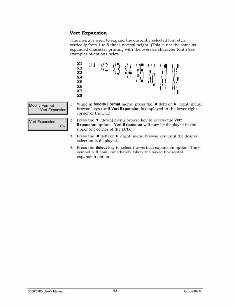
5050/5100 User’s Manual GEK-99044E62
Vert ExpansionThis menu is used to expand the currently selected font stylevertically from 1 to 8 times normal height. (This is not the same asexpanded character printing with the oversize character font.) Seeexamples of options below.
1. While in Modify Format menu, press the ◄ (left) or ► (right) menubrowse keys until Vert Expansion is displayed in the lower rightcorner of the LCD.
2. Press the ▼ (down) menu browse key to access the VertExpansion options. Vert Expansion will now be displayed in theupper left corner of the LCD.
3. Press the ◄ (left) or ► (right) menu browse key until the desiredselection is displayed.
4. Press the Select key to select the vertical expansion option. The <symbol will now immediately follow the saved horizontalexpansion option.
Modify FormatVert Expansion
Vert ExpansionX1<
X1X2X3X4X5X6X7X8

5050/5100 User’s Manual Chapter 5. Using the Setup Menu63
VertExp OptionsThis menu is used to control how the expanded characters willappear. (See Set Up Menu Map in Appendix I for available selections.)Although all expanded characters are printed from the top down, thepositioning on the page will make them appear to “group” up or “sag”down when compared to normally printed characters on the sameline. See examples below.
1. While in Modify Format menu, press the ◄ (left) or ► (right) menubrowse keys until VertExp Options is displayed in the lower rightcorner of the LCD.
2. Press the ▼ (down) menu browse key to access the VertExpOptions options. VertExp Options will now be displayed in theupper left corner of the LCD.
3. Press the ◄ (left) or ► (right) menu browse key until the desiredselection is displayed.
4. Press the Select key to select a VertExp Options option. The <symbol will now immediately follow the saved VertExp Optionsoption.
Modify FormatVertExp Options
VertExp OptionsDefault (top)<
BASELINE
DEFAULT
“GROUP” UP
“SAG”

5050/5100 User’s Manual GEK-99044E64
Print ModifiersThis menu is used to select font enhancements.
Option MeaningDoubleStrike
Printer will print each text charactertwice by double striking each dotdirectly without offset.
Emphasized
Printer will print the dots in eachcharacter twice with the second strikehaving a slight horizontal offset.
1. While in Modify Format menu, press the ◄ (left) or ► (right) menubrowse keys until Print Modifiers is displayed in the lower rightcorner of the LCD.
2. Press the ▼ (down) menu browse key to access the Print Modifiersoptions. Print Modifiers will now be displayed in the upper leftcorner of the LCD.
3. Press the ◄ (left) or ► (right) menu browse key until the desiredselection is displayed.
4. Press the Select key to select the Print Modifier option. The <symbol will now immediately follow the saved Print Modifieroption.
Modify FormatPrint Modifiers
Print ModifiersEmphasized
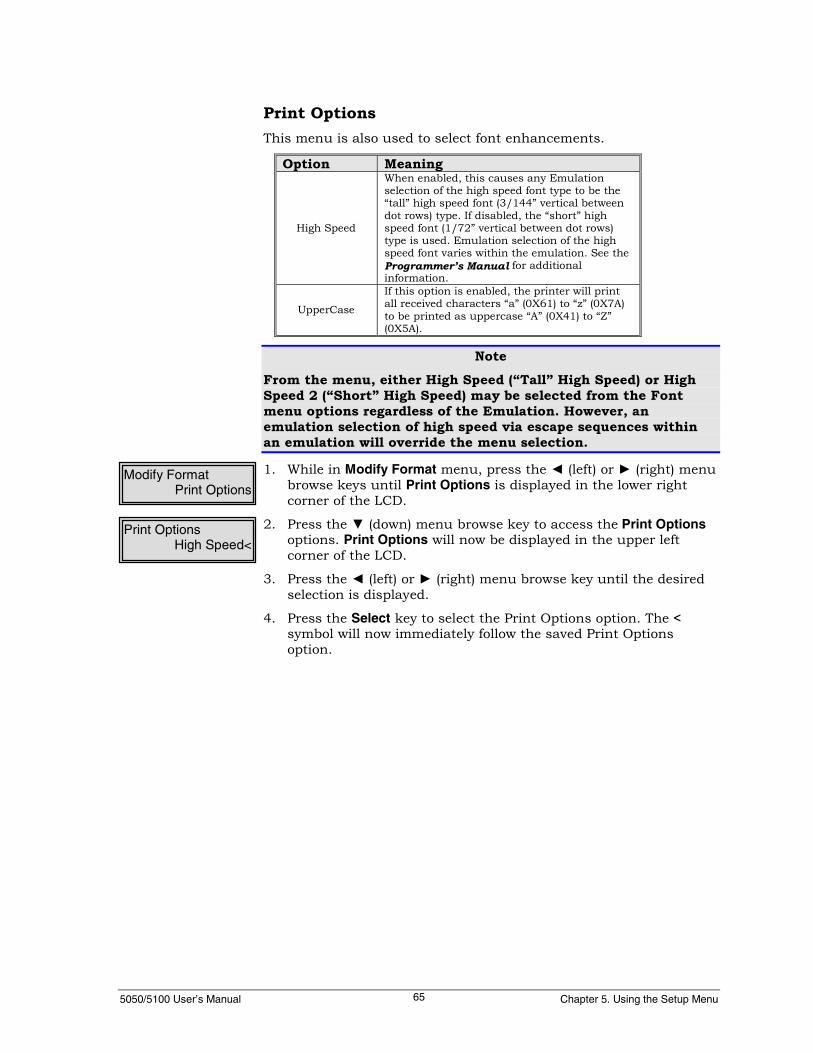
5050/5100 User’s Manual Chapter 5. Using the Setup Menu65
Print OptionsThis menu is also used to select font enhancements.
Option Meaning
High Speed
When enabled, this causes any Emulationselection of the high speed font type to be the“tall” high speed font (3/144” vertical betweendot rows) type. If disabled, the “short” highspeed font (1/72” vertical between dot rows)type is used. Emulation selection of the highspeed font varies within the emulation. See theProgrammer’s Manual for additionalinformation.
UpperCase
If this option is enabled, the printer will printall received characters “a” (0X61) to “z” (0X7A)to be printed as uppercase “A” (0X41) to “Z”(0X5A).
NoteFrom the menu, either High Speed (“Tall” High Speed) or HighSpeed 2 (“Short” High Speed) may be selected from the Fontmenu options regardless of the Emulation. However, anemulation selection of high speed via escape sequences withinan emulation will override the menu selection.
1. While in Modify Format menu, press the ◄ (left) or ► (right) menubrowse keys until Print Options is displayed in the lower rightcorner of the LCD.
2. Press the ▼ (down) menu browse key to access the Print Optionsoptions. Print Options will now be displayed in the upper leftcorner of the LCD.
3. Press the ◄ (left) or ► (right) menu browse key until the desiredselection is displayed.
4. Press the Select key to select the Print Options option. The <symbol will now immediately follow the saved Print Optionsoption.
Modify FormatPrint Options
Print OptionsHigh Speed<

5050/5100 User’s Manual GEK-99044E66
Print ControlThis menu and its sub-menus are used to set printer response to linetermination and certain positioning commands sent by the hostsystem.
1. While in the Set Up menu, press the ◄ (left) or ► (right) menubrowse key until Print Control is displayed in the lower rightcorner of the LCD.
2. Press the ▼ (down) menu browse key to access the Print Controlsub-menus.
The following describes the sub-menus and options available:
Define LFThis menu is used to define the action of the printer upon receiving aline feed character.
1. While in the Print Control menu, press the ◄ (left) or ► (right)menu browse keys until Define LF is displayed in the lower rightcorner of the LCD.
2. Press the ▼ (down) menu browse key to access the Define LFoptions.
3. Press the ◄ (left) or ► (right) menu browse key until the desiredoption is displayed. Press the Select key to enable or disable anoption. The < symbol will immediately follow an enabled option.
Define CRThis menu is used to define the action of the printer upon receiving acarriage return character.
1. While in the Print Control menu, press the ◄ (left) or ► (right)menu browse keys until Define CR is displayed in the lower rightcorner of the LCD.
2. Press the ▼ (down) menu browse key to access the Define CRoptions.
3. Press the ◄ (left) or ► (right) menu browse key until the desiredoption is displayed. Press the Select key to enable or disable anoption. The < symbol will immediately follow an enabled option.
Set UpPrint Control
Define LFLF = CR + LF<
Define CRCR = CR <
Print ControlDefine CR

5050/5100 User’s Manual Chapter 5. Using the Setup Menu67
Define FFThis menu is used to define the action of the printer, upon receiving aform feed character.
1. While in the Print Control menu, press the ◄ (left) or ► (right)menu browse keys until Define FF is displayed in the lower rightcorner of the LCD.
2. Press the ▼ (down) menu browse key to access the Define FFoptions.
3. Press the ◄ (left) or ► (right) menu browse key until the desiredoption is displayed. Press the Select key to enable or disable anoption. The < symbol will immediately follow an enabled option.
Define HTThis menu is used to define the action of the printer upon receiving ahorizontal tab character.
1. While in the Print Control menu, press the ◄ (left) or ► (right)menu browse keys until Define T is displayed in the lower rightcorner of the LCD.
2. Press the ▼ (down) menu browse key to access the Define HToptions.
3. Press the ◄ (left) or ► (right) menu browse key until the desiredoption is displayed. Press the Select key to enable or disable anoption. The < symbol will immediately follow an enabled option.
VertMoveThis menu is used to define the vertical movement behavior for theprinter.
1. While in the Print Control menu, press the ◄ (left) or ► (right)menu browse keys until VertMove is displayed in the lower rightcorner of the LCD.
2. Press the ▼ (down) menu browse key to access the VertMoveoptions.
3. Press the ◄ (left) or ► (right) menu browse key until the desiredoption is displayed. Press the Select key to enable or disable anoption. The < symbol will immediately follow an enabled option.
Define FFFF = FF<
Print ControlDefine FF
Define HTNotabs = SPACE<
Print ControlDefine HT
VertMoveVM=CR+VM<
Print ControlVertMove

5050/5100 User’s Manual GEK-99044E68
AutoWrapThis menu is used to enable/disable the auto wrapping option for theprinter. If set to enable, autowrapping will occur at the right margin.If this option is disabled, no auto wrap will occur and data will betruncated.
1. While in the Print Control menu, press the ◄ (left) or ► (right)menu browse keys until AutoWrap is displayed in the lower rightcorner of the LCD.
2. Press the ▼ (down) menu browse key to access the AutoWrapoptions.
3. Press the ◄ (left) or ► (right) menu browse key until the desiredoption is displayed. Press the Select key to enable or disable anoption. The < symbol will immediately follow an enabled option.
FF @ TOFThis menu is used to define form feed with top of form behavior forthe printer. If enabled, the printer will ignore a form feed character, ifthe printer is already at the top of form.
1. While in the Print Control menu, press the ◄ (left) or ► (right)menu browse keys until FF @ TOF is displayed in the lower rightcorner of the LCD.
2. Press the ▼ (down) menu browse key to access the FF @ TOFoptions.
3. Press the ◄ (left) or ► (right) menu browse key until the desiredoption is displayed. Press the Select key to enable or disable anoption. The < symbol will immediately follow an enabled option.
AutoWrapEnable<
Print ControlAutoWrap
FF @ TOFEnable<
Print ControlFF @ TOF
5050/5100 User’s Manual Chapter 5. Using the Setup Menu69
GENPTROPTSThis menu is used to set general printer options. See the GeneralPrinter Options, Group 1 and Group 2 on pages 184 and 185 inAppendix G for additional information.
NoteTo print the Euro currency symbol, see the General PrinterOptions, Group 1 and Group 2 on pages 184 and 185 in AppendixG for settings.
1. While in the Set Up menu, press ◄ (left) or ► (right) menu browsekey until GenPtrOpts is displayed in the lower right corner of theLCD.
2. Press the ▼ (down) menu browse key to access the GenPtrOptsoptions.
3. Press the ◄ (left) or ► (right) menu browse key until the desiredGroup 1 or Group 2 is displayed.
4. Press the Select key to select Group 1 or Group 2.
5. Press the ◄ (left) or ► (right) menu browse key until the desiredoption is displayed. Press the Select key to either enable ordisable an option. The < symbol will immediately follow anenabled option.
Slew RateThis menu is used to set the speed at which paper can be movedthrough the printer during printing operations (form feeds, verticalmoves, etc.) The reduced slew speed can be useful if the printer isexperiencing trouble with heavy stock or stiff multi-part forms. Usingthe reduced slew speed will reduce throughput.
1. While in Modify Format menu, press the ◄ (left) or ► (right) menubrowse keys until Slew Rate is displayed in the lower right cornerof the LCD.
2. Press the ▼ (down) menu browse key to access the Slew Rateoptions. Slew Rate will now be displayed in the upper left cornerof the LCD.
3. Press the ◄ (left) or ► (right) menu browse key until the desiredselection is displayed.
4. Press the Select key to select the Slew Rate option. The < symbolwill now immediately follow the saved Slew Rate option.
Modify FormatSlew Rate
Slew RateNormal<
Set UpGenPtrOpts
GenPtrOptsGroup 1
Group 101<

5050/5100 User’s Manual GEK-99044E70
Save FormatThis is the final step used to modify or create a stored format. (See“Format” for additional information.) This menu is used to save theformat settings created after selecting and modifying a format. Whensaving a format, the operator is given the choice to save the format tothe active (the format chosen from the control panel) or as a blankformat, if available. There are ten possible customer-defined formatslots available. It is recommended that each customer-defined formatbe saved with a unique name.
NotePrint a Format Page printout and save for future reference or inthe event a format(s) needs to be re-configured. See “Show” inChapter 4, page 42, for instructions to print a Format Page.
1. While in Format menu, press the ◄ (left) to ► (right) menubrowse key until Save Format appears in the lower right corner ofthe LCD.
2. Press the ▼ (down) menu browse key. Save Format will appear inthe upper left corner of the LCD.
3. Press the ◄ (left) or ► (right) menu browse key until the desiredformat is listed. If no previously saved format name exists, thedefault format names are Default through Blank Format 1 ... 9.
4. Press the Select key to select the format slot. Choosing a blankformat will immediately display the format name modified underFormat Name.
5. Press the Select key to confirm this format name. Press the Clearkey to exit this option.
FormatSave Format
Save FormatDefault
5050/5100 User’s Manual Chapter 5. Using the Setup Menu71
SELECT I/FThe Select I/F menu allows the operator to select a specific type ofinterface the printer will be using. The factory default setting ismultisource, which activates all interfaces. The multisource setting issufficient for most applications. (See the Operator Menu Map inAppendix I for available selections.)
NoteMultiple interfaces can be selected. For example, Serial andParallel interfaces can be active at the same time. If a selectionother than Multisource is selected, the Multisource interface isunselected. If Multisource is selected, all other interfaces areautomatically unselected.
1. While in Set Up menu, press the ◄ (left) or ► (right) menu browsekeys until Select I/F is displayed in the lower right corner of theLCD.
2. Press the ▼ (down) menu browse key to access the interfaceoptions.
3. Press the ◄ (left) or ► (right) menu browse keys until theinterface type desired is displayed in the lower right corner of theLCD.
4. Press the Select key to select an interface type. The < symbol willnow immediately follow the saved interface type.
I/F SETTINGSThis menu and its sub-menus are used to setup the printer’sinterface options and the serial interface parameters. See the Set UpMenu Map in Appendix I for available selections.
1. While in the Set Up menu, press the ◄ (left) or ► (right) menubrowse key until I/F Settings is displayed in the lower right cornerof the LCD.
2. Press the ▼ (down) menu browse key to access the sub-menuoptions. I/F Settings will be displayed in the upper left corner ofthe LCD.
3. Press the ◄ (left) or ► (right) menu browse key until the desiredinterface is displayed. Press the Select key to select MultiSource,Parallel Setup, Serial Setup, Expansion 1, or Expansion 2.
The following describes the selections available.
Set UpSelect I/F
Set UpI/F Settings
I/F SettingsMultiSource

5050/5100 User’s Manual GEK-99044E72
MultiSourceThis sub-menu is used to select the multiple interface option. Inmultisource mode, all available interfaces are enabled. If receiveddata stops on the currently active port, the next port is checked forreceived data after the “Delay Seconds” time has elapsed and no moredata has been received from the last port that received data.
1. While in the I/F Settings menu, press the ◄ (left) or ► (right)menu browse key until MultiSource is displayed in the lower rightcorner of the LCD.
2. Press the Select key to select MultiSource. Delay Seconds will bedisplayed in the upper left corner of the display and the currentsetting will be displayed in the lower right corner of the display.Notice the cursor (underline) is now shown under the first digitand the default number is 000. The four menu browse keys revertto data entry operation. The horizontal ◄ ► (left or right) keysposition the cursor (underline) under the digit to be changed; thevertical ▲ ▼ (up or down) menu browse keysincrement/decrement the selected digit by one.
3. Press the Clear key after all changes are complete and thedesired value is displayed in the lower right corner of the LCD.The valid range of values for this option is 006 to 030. Pressingthe Clear key does not erase the values entered, but does allowthe user to exit the User Set menu.
Note
Repeat this section if further changes are necessary.
I/F SettingsMultiSource
Delay Seconds006

5050/5100 User’s Manual Chapter 5. Using the Setup Menu73
Parallel SetupThis menu option is used to configure the parallel interface only. Theoption No Fault PO & Off, under this menu may be enabled ordisabled. In the default condition (disabled), the parallel fault leadwill be set to true for either of the two conditions, paper out or if inthe offline condition. If enabled, the parallel fault lead will not be setto true for either (or both) of the conditions, paper out and/or offline.The TCP/IP options is a compatibility option for Genicom 4810/4840printers. The IP Address, Netmask and Router IP Address of Genicommodels 98-205-153 and 98-305-153 NIC print servers may beprogrammed via the control panel menu using the IEEE1284 parallelinterface. This feature is restricted to these specific Genicom modelethernet print servers and as such utilizes a proprietary Genicomprotocol that differs from the bi-directional 1284 protocolspecifications.
1. While in the I/F Settings menu, press the ◄ (left) or ► (right)menu browse key until Parallel Setup is displayed in the lowerright corner of the LCD.
2. Press the ▼ (down) menu browse key to select Parallel Setup.Parallel Setup will be displayed in the upper left corner of thedisplay and the current setting will be displayed in the lower rightcorner of the display.
3. Press the Select key to enable or disable the setting. The < symbolwill now immediately follow the enabled setting.
To set the IP Address, or Router IP Address, use the followingprocedures:
1. While in the Parallel Setup options, press the ◄ (left) or ► (right)menu browse keys until TCP/IP is displayed in the lower rightcorner of the LCD.
2. Press the Select key. TCP/IP will be displayed in the upper leftcorner of the LCD.
3. Press the ◄ (left) or ► (right) menu browse keys until IP Address,Netmask or Router IP Addr is displayed in the lower right corner ofthe LCD. (The example to the left is for the IP Address setting.)
4. Press the Select key. Notice the cursor (underline) is now shownunder the first digit. The horizontal ◄ ► (left or right) menubrowse keys position the cursor (underline) under the digit to bechanged; the vertical ▲ ▼ (up or down) increment/decrement theselected digit by one.
5. Press the Clear key after all changes are complete and thedesired value is displayed in the lower right corner of the LCD.Pressing the Clear key does not erase the values entered, but doesallow the user to exit the User Set menu.
NoteRepeat this section if further changes are necessary. Cycle powerafter entries to activate changes.
I/F SettingsParallel Setup
Parallel SetupNo Fault PO & OFF
Parallel SetupTCP/IP
TCP/IPIP Address
IP Address000.000.000.000<

5050/5100 User’s Manual GEK-99044E74
SerialThis menu option is used to configure the serial interface. See the SetUp Menu Map in Appendix I for a complete view of selections and/orsubmenus available.
Use the following procedure to select the Serial option:
▪ While in the I/F Settings menu, press the ◄ (left) or ► (right)menu browse key until Serial is displayed in the lower rightcorner of the LCD.
The following describes the selections available.
Serial TypeThis menu is used to select the serial interface type, RS232C orRS422.
NoteThe Serial Type selected determines which menu items appearunder the Serial Setup menu.
1. While in the I/F Settings menu, press the ▼ (down) menu browsekey. Serial Type is displayed in the lower right corner of the LCD.
2. Press the ▼ (down) menu browse key to access the Serial Typeoptions.
3. Press the ◄ (left) or ► (right) menu browse key until the desiredsetting is displayed in the lower right corner of the display.
4. Press the Select key to enable a setting or disable a setting. The <symbol will now immediately follow the selected setting.
I/F SettingsSerial Type
Serial TypeRS232C <

5050/5100 User’s Manual Chapter 5. Using the Setup Menu75
Serial SetupThis menu, its sub-menus, and options are used to change settingsfor the serial interface. See the Set Up Menu Map in Appendix I for acomplete listing of available selections.
NoteThe Serial Type selected determines which menu items appearunder the Serial Setup menu.
1. While in the I/F Settings menu, press the ▼ (down) menu browsekey. Serial Setup will be displayed in the lower right corner of theLCD.
2. Press the ▼ (down) menu browse key to access the Serial Setupoptions.
3. Press the ◄ (left) or ► (right) menu browse key until the desiredsetting is displayed in the lower right corner of the LCD. Pressthe ▼ (down) menu browse or Select key to access the SerialSetup sub-menus.
The following describes the selections available.
ProtocolThis sub-menu is used to select protocol settings for the serialinterface (both RS232 and RS422). See Set Up Menu Map on page206 in Appendix I for a complete listing of available selections.
1. While in the Serial Setup menu, press the ▼ (down) menu browsekey until Protocol is displayed in the lower right corner of thedisplay menu.
2. Press the ▼ (down) menu browse key. Protocol will be displayedin the upper left corner of the LCD.
3. Press the ◄ (left) or ► (right) menu browse key until the desiredprotocol sub-menu selection is displayed in the lower right cornerof the LCD.
The following describes the selections available.
I/F SettingsSerial Setup
Serial SetupProtocol
ProtocolXON/XOFF

5050/5100 User’s Manual GEK-99044E76
XON/XOFFThis option is used to configure the XON/XOFF (also known asDC1/DC3) settings for both RS232 and RS422 serial type.
Option MeaningReady/Busy XOFF is transmitted to the host by the printer when
the print is unable to receive more data. XON istransmitted to the host by the printer when theprinter is ready to receive more data.
ON/OFFline XOFF is transmitted by the printer when it goes offlineand XON is transmitted by the printer when it goesonline.
Fault XOFF is transmitted by the printer when a fault isdetected. XON is transmitted by the printer when thefault has been cleared.
Robust XOFF Printer sends XOFF signal every 20 characters untilhost stops sending and buffer is consumed to belowthe high trip point.
Robust XON Printer sends XON every 3 seconds while ONLINE,idle, and no faults.
1. While in the Protocol menu, press the ◄ (left) or ► (right) menubrowse key until the XON/XOFF option is displayed.
2. Press the ▼ (down) menu browse key to access the XON/XOFFoptions.
3. Press the ◄ (left) or ► (right) menu browse keys until the desiredXON/XOFF option is displayed in the LCD.
4. Press the Select key to enable or disable the setting. The < symbolwill now immediately follow the selected (saved) setting.
CD(DTR)This option is used to configure CD(DTR) settings for RS232 serialtype. This is also known as Data Terminal Ready.
Option MeaningReady/Busy DTR signal is used to reflect if the printer is ready
(able to receive data) or busy (currently unable toreceive data.)
ON/OFFline DTR signal is used to reflect the printer is online oroffline.
Fault DTR signal is used to reflect whether a faultcondition exists.
1. While in the Protocol menu, press the ◄ (left) or ► (right) menubrowse key until the CD(DTR) option is displayed.
2. Press the ▼ (down) menu browse key to access the CD(DTR)options.
3. Press the ◄ (left) or ► (right) menu browse keys until the desiredCD(DTR) option is displayed in the LCD.
4. Press the Select key to enable or disable an option. The < symbolwill now immediately follow the enabled setting.
ProtocolXON/XOFF
ProtocolCD(DTR)
XON/XOFFReady/Busy
CD(DTR)Ready/Busy
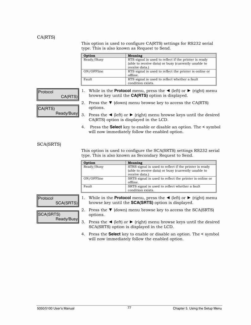
5050/5100 User’s Manual Chapter 5. Using the Setup Menu77
CA(RTS)This option is used to configure CA(RTS) settings for RS232 serialtype. This is also known as Request to Send.
Option MeaningReady/Busy RTS signal is used to reflect if the printer is ready
(able to receive data) or busy (currently unable toreceive data.)
ON/OFFline RTS signal is used to reflect the printer is online oroffline.
Fault RTS signal is used to reflect whether a faultcondition exists.
1. While in the Protocol menu, press the ◄ (left) or ► (right) menubrowse key until the CA(RTS) option is displayed.
2. Press the ▼ (down) menu browse key to access the CA(RTS)options.
3. Press the ◄ (left) or ► (right) menu browse keys until the desiredCA(RTS) option is displayed in the LCD.
4. Press the Select key to enable or disable an option. The < symbolwill now immediately follow the enabled option.
SCA(SRTS)This option is used to configure the SCA(SRTS) settings RS232 serialtype. This is also known as Secondary Request to Send.
Option MeaningReady/Busy STRS signal is used to reflect if the printer is ready
(able to receive data) or busy (currently unable toreceive data.)
ON/OFFline SRTS signal is used to reflect the printer is online oroffline.
Fault SRTS signal is used to reflect whether a faultcondition exists.
1. While in the Protocol menu, press the ◄ (left) or ► (right) menubrowse key until the SCA(SRTS) option is displayed.
2. Press the ▼ (down) menu browse key to access the SCA(SRTS)options.
3. Press the ◄ (left) or ► (right) menu browse keys until the desiredSCA(SRTS) option is displayed in the LCD.
4. Press the Select key to enable or disable an option. The < symbolwill now immediately follow the enabled option.
ProtocolCA(RTS)
ProtocolSCA(SRTS)
CA(RTS)Ready/Busy
SCA(SRTS)Ready/Busy

5050/5100 User’s Manual GEK-99044E78
ETX/ACKThis option is used to configure the ETX/ACK (End ofText/Acknowledge) settings for RS232 serial type. ETX/ACK is aserial validity check protocol, where the host appends the ETX (end oftext) code (0X03) at the end of each data block and waits to receivean acknowledge character (ACK=0X06) from the printer, within sometime period, prior to sending the next block of data. This is not anETX/ACK/NAK protocol. The printer never responds with a NAK(0X15) even if errors are detected.
Option MeaningDisable The ETX is ignored and no further action is taken (it
is treated as just another data character.)Immediate The printer controller immediately replies to an ETX
with an ACK.On Prn Complete The printer waits until the data block has been
printed prior to sending the host the ACK character.Flow Controlled Allows printer to inhibit the transmission of the ACK
response if the printer is in the Off Line state, in aprinter Fault condition or when received data rechesthe high water (Busy) threshold. The respective ACKwill be transmitted after the printer returns to the OnLine state, the Fault is cleared or the data in theinput buffer is decreased to the low water threshold.This option will transmitt the ACK immediately ifthere are no restrictions.
NoteOn Prn Complete may cause a reduction in throughput due to thehost waiting for the ACK before sending more data.
1. While in the Protocol menu, press the ◄ (left) or ► (right) menubrowse key until the ETX/ACK option is displayed.
2. Press the ▼ (down) menu browse key to access the ETX/ACKoptions.
3. Press the ◄ (left) or ► (right) menu browse keys until the desiredETX/ACK option is displayed in the LCD.
4. Press the Select key to enable or disable the setting. See the SetUp Menu Map for available selections. The < symbol will nowimmediately follow the enabled option.
Inhibit XmitThis sub-menu is used to configure an Inhibit Xmit setting for theserial setup for RS232 serial type.
Option MeaningNever The host is prevented from controlling the printer’s
ability to transmit back to the host via the CB (CTS)hardware lead.
Via CB (CTS) The host can control the inhibit transmit with theClear to Send (CB) lead.
1. While in the Serial Setup menu, press the ◄ (left) or ► (right)menu browse key until Inhibit Xmit is displayed in the lower rightcorner of the display menu.
Serial SetupInhibit Xmit
ProtocolETX/ACK
ETX/ACKDisable

5050/5100 User’s Manual Chapter 5. Using the Setup Menu79
2. Press the ▼ (down) menu browse key to access the Inhibit Xmitoptions.
3. Press the ◄ (left) or ► (right) menu browse key until the desiredprotocol sub-menu option is displayed in the lower right corner ofthe LCD.
4. Press the Select key to enable or disable an option. The < symbolwill now immediately follow the enabled option.
Lead PolarityThis sub-menu is used to configure lead polarity settings for RS232serial type. There are five additional sub-menus available.
MeaningType of SignalSent High LowCD(DTR)CA (RTS)SCA (STRS)CB (CTS)CC (DSR)
Signal is active high. Signal is active low.
1. While in the Serial Setup menu, press the ◄ (left) or ► (right)menu browse key until Lead Polarity is displayed in the lowerright corner of the display menu.
2. Press the ▼ (down) menu browse key to access the Lead Polaritysub-menus.
3. Press the ◄ (left) or ► (right) menu browse key until the desiredlead polarity sub-menu selection is displayed in the lower rightcorner of the LCD.
4. Press the ▼ (down) menu browse key to access setting for thelead sub-menu. Press the ◄ (left) or ► (right) menu browse keyuntil the desired setting is displayed in the lower right corner ofthe LCD.
5. Press the Select key to enable or disable an option. The < symbolwill immediately follow the enabled option.
Data BitsThis sub-menu is used to configure the number of data bits percharacter for serial RS232. There are two settings under the DataBits option, 7 Bits or 8 Bits. Set the data bits equal to that of the hostcomputer.
1. While in the Serial Setup menu, press the ◄ (left) or ► (right)menu browse key until Data Bits is displayed in the lower rightcorner of the display menu.
2. Press the ▼ (down) menu browse key. Data Bits will be displayedin the upper left corner of the LCD.
3. Press the ◄ (left) or ► (right) menu browse key until the desiredselection is displayed in the lower right corner of the LCD. Pressthe Select key to enable or disable an option. The < symbol willnow immediately follow the enabled option.
Serial SetupLead Polarity
Inhibit XmitNever
Serial SetupData Bits
Data Bits7 Bits

5050/5100 User’s Manual GEK-99044E80
ParityThis sub-menu is used to configure a parity setting for the serialinterface. Parity is a serial interface parameter used for errordetection.
Option Meaning if Enabled
No Parity Bit The serial character does not have this bit andparity checking is disabled.
Ignore The character does contain the parity bit, but it isignored by the printer with no error detection beingmade. The bit may be a logical one or zero.
Even The parity bit set by the host is such that there isan even number of logical “ones” in the character.The printer checks for an even number of “ones”and flags a parity error if there is an odd number of“ones” (including the parity bit).
Odd The parity bit is set by the host such that there isan odd number of logical “ones” in the character.The printer checks for an odd number of “ones” andflags a parity error if there is an even number of“ones” (including the parity bit).
Space The parity bit set by the host to a logical zero bit.The printer checks the parity bit for zero and flags aparity error if it is a logical one.
Mark The parity bit set by the host to a logical one bit.The printer checks the parity bit of one and flags aparity error if it is a logical zero.
1. While in the Serial Setup menu, press the ◄ (left) or ► (right)menu browse key until Parity is displayed in the lower rightcorner of the display menu.
2. Press the ▼ (down) menu browse key. Parity will be displayed inthe upper left corner of the LCD.
3. Press the ◄ (left) or ► (right) menu browse key until the desiredselection is displayed in the lower right corner of the LCD. Pressthe Select key to enable or disable an option. The < symbol willnow immediately follow the enabled option.
Serial SetupParity
ParityNo Parity Bit<
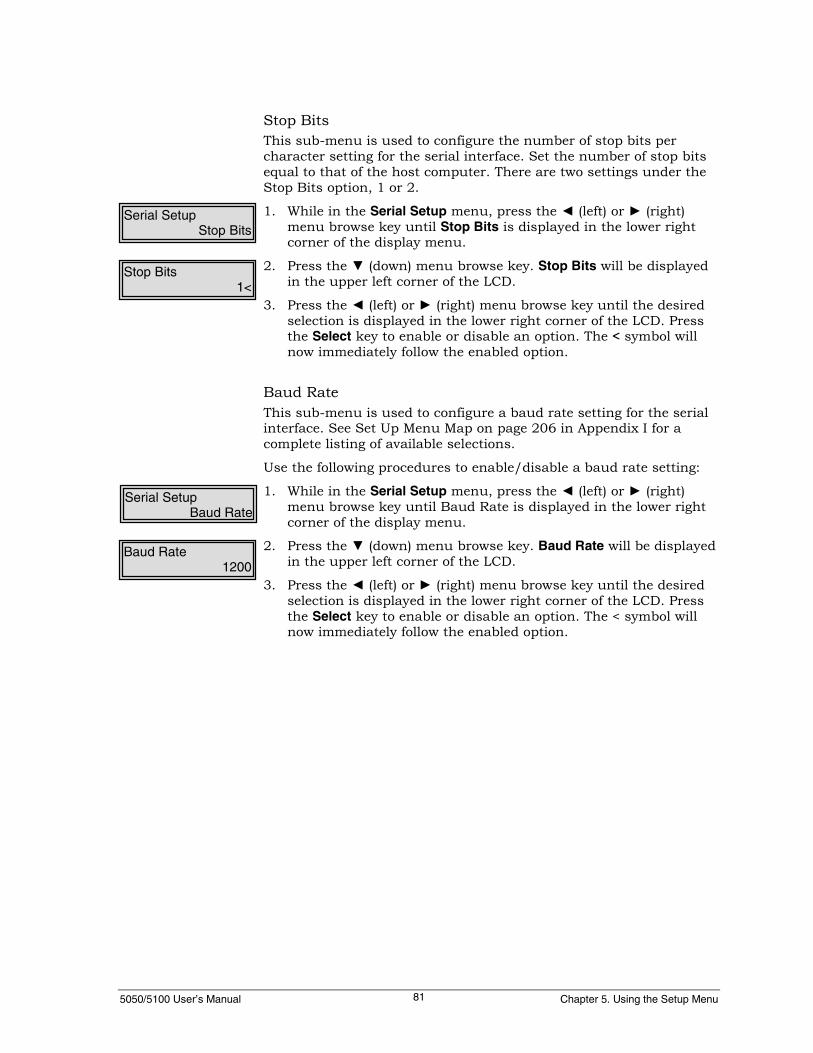
5050/5100 User’s Manual Chapter 5. Using the Setup Menu81
Stop BitsThis sub-menu is used to configure the number of stop bits percharacter setting for the serial interface. Set the number of stop bitsequal to that of the host computer. There are two settings under theStop Bits option, 1 or 2.
1. While in the Serial Setup menu, press the ◄ (left) or ► (right)menu browse key until Stop Bits is displayed in the lower rightcorner of the display menu.
2. Press the ▼ (down) menu browse key. Stop Bits will be displayedin the upper left corner of the LCD.
3. Press the ◄ (left) or ► (right) menu browse key until the desiredselection is displayed in the lower right corner of the LCD. Pressthe Select key to enable or disable an option. The < symbol willnow immediately follow the enabled option.
Baud RateThis sub-menu is used to configure a baud rate setting for the serialinterface. See Set Up Menu Map on page 206 in Appendix I for acomplete listing of available selections.
Use the following procedures to enable/disable a baud rate setting:
1. While in the Serial Setup menu, press the ◄ (left) or ► (right)menu browse key until Baud Rate is displayed in the lower rightcorner of the display menu.
2. Press the ▼ (down) menu browse key. Baud Rate will be displayedin the upper left corner of the LCD.
3. Press the ◄ (left) or ► (right) menu browse key until the desiredselection is displayed in the lower right corner of the LCD. Pressthe Select key to enable or disable an option. The < symbol willnow immediately follow the enabled option.
Serial SetupStop Bits
Stop Bits1<
Serial SetupBaud Rate
Baud Rate1200

5050/5100 User’s Manual GEK-99044E82
High Trip Pt%This sub-menu is used to configure a High Trip Point setting for theserial interface as a percentage of total buffer size. This settingconfigures the point where the printer transmits a signal to the hostwhen the buffer is approaching being full. For example, the defaultsetting is set to 80. This means the printer will send a full buffersignal to the host that the buffer has filled to 80% capacity. The 20%of the buffer acts as a cushion allowing enough time for the printer toprocess the data in its buffer while giving the host time to stoptransmitting data before the buffer is completely (100%) full and datais lost.
1. While in the Serial Setup menu, press the ◄ (left) or ► (right)menu browse key until High Trip Pt% is displayed in the lowerright corner of the display menu.
2. Press the Select key. High Trip Pt% will be displayed in the upperleft corner of the LCD, and the current setting will be displayed inthe lower right corner of the LCD. Notice the cursor (underline) isnow shown under the first digit and the default number is 80.The four menu browse keys revert to data entry operation. Thehorizontal ◄ ► (left or right) keys position the cursor (underline)under the digit to be changed; the vertical ▲ ▼ (up or down keysincrement/decrement the selected digit by one.
3. Press the Clear key after all changes are complete and thedesired value is displayed in the lower right corner of the LCD.Pressing the Clear key does not erase the values entered, but doesallow the user to exit the User Set menu.
NoteRepeat this section if further changes are necessary.
High Trip Pt%80

5050/5100 User’s Manual Chapter 5. Using the Setup Menu83
Expansion1/Expansion2This menu option is used to configure the settings for the optionalI/O cards in the two expansion slots located in the rear of the printer.The menu options under Expansion1 or Expansion2 are the same. Ifnot labeled, Expansion1 slot is closest to the left side of the printerwhile facing the rear of the printer for the 5050/5100 cabinet models.Make changes to Expansion1 or Expansion2 settings according to theslot installed. There are six sub-menus under this menu.
1. While in the I/F Settings menu, press the ◄ (left) or ► (right)menu browse key until Expansion1 or Expansion2 is located inthe lower right corner of the LCD.
2. Press the ▼ (down) menu browse, or the Select key, to access theExpansion1 or Expansion2 menu.
The following describes the selections available:
Legacy ParallelThis sub-menu is used to configure Legacy Parallel settings for theLegacy Parallel I/O card installed in the expansion slot of the printer.There are 2 sub-menus under this option, I/F Type (Hardware) andI/F Straps (Software).
1. While in the Expansion1 or Expansion2 menu, press the ◄ (left)or ► (right) menu browse key until Legacy Parallel is displayed inthe lower right corner of the LCD.
2. Press the ▼ (down) menu browse key. Legacy Parallel will bedisplayed in the upper left corner of the LCD.
3. Press the ◄ (left) or ► (right) menu browse key until I/F Type isdisplayed in the lower right corner of the LCD.
4. Press the ▼ (down) menu browse key to access the I/F Typeoptions. A currently active option will be displayed in the lowerright corner of the LCD immediately followed by the < symbol.
The following describes the selections available.
II/F SettingsExpansion1
Expansion1Legacy Parallel
Legacy ParallelI/F Type
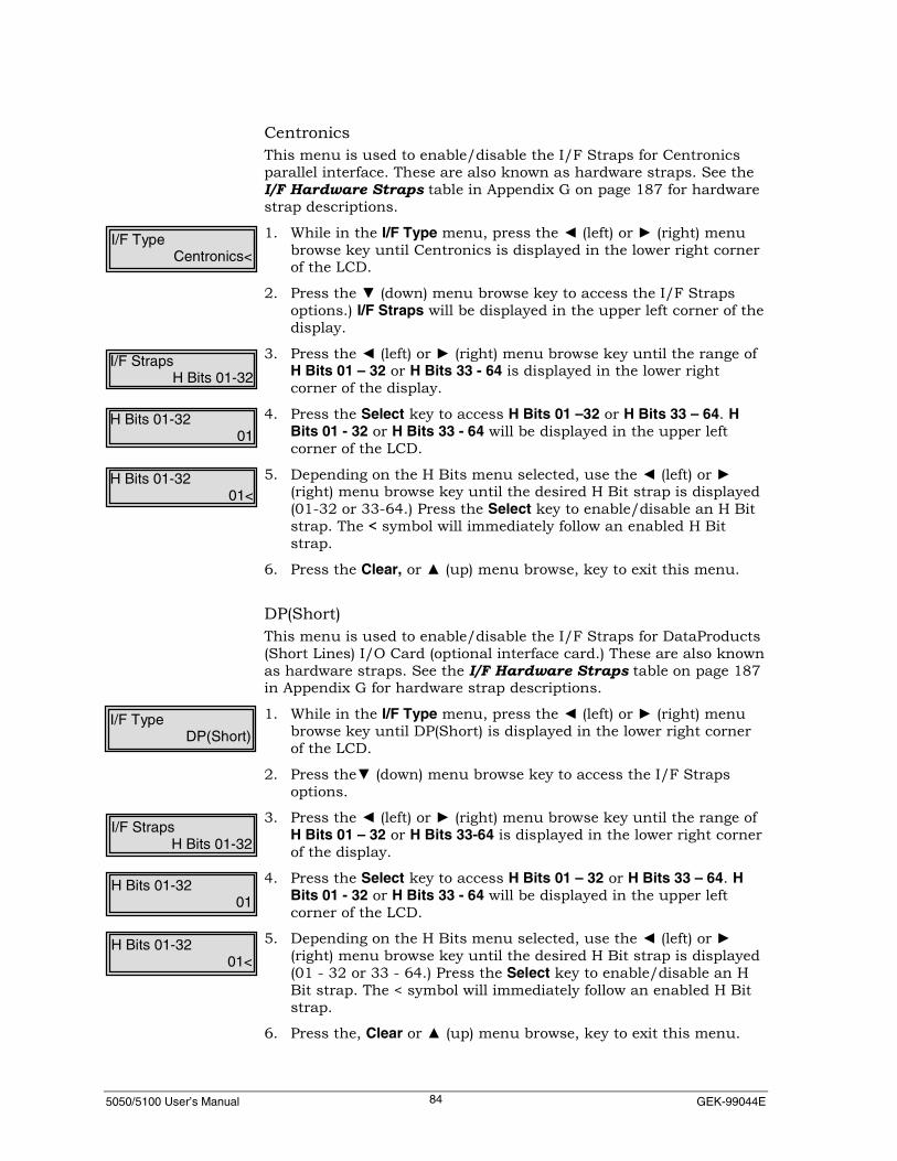
5050/5100 User’s Manual GEK-99044E84
CentronicsThis menu is used to enable/disable the I/F Straps for Centronicsparallel interface. These are also known as hardware straps. See theI/F Hardware Straps table in Appendix G on page 187 for hardwarestrap descriptions.
1. While in the I/F Type menu, press the ◄ (left) or ► (right) menubrowse key until Centronics is displayed in the lower right cornerof the LCD.
2. Press the ▼ (down) menu browse key to access the I/F Strapsoptions.) I/F Straps will be displayed in the upper left corner of thedisplay.
3. Press the ◄ (left) or ► (right) menu browse key until the range ofH Bits 01 – 32 or H Bits 33 - 64 is displayed in the lower rightcorner of the display.
4. Press the Select key to access H Bits 01 –32 or H Bits 33 – 64. HBits 01 - 32 or H Bits 33 - 64 will be displayed in the upper leftcorner of the LCD.
5. Depending on the H Bits menu selected, use the ◄ (left) or ►(right) menu browse key until the desired H Bit strap is displayed(01-32 or 33-64.) Press the Select key to enable/disable an H Bitstrap. The < symbol will immediately follow an enabled H Bitstrap.
6. Press the Clear, or ▲ (up) menu browse, key to exit this menu.
DP(Short)This menu is used to enable/disable the I/F Straps for DataProducts(Short Lines) I/O Card (optional interface card.) These are also knownas hardware straps. See the I/F Hardware Straps table on page 187in Appendix G for hardware strap descriptions.
1. While in the I/F Type menu, press the ◄ (left) or ► (right) menubrowse key until DP(Short) is displayed in the lower right cornerof the LCD.
2. Press the▼ (down) menu browse key to access the I/F Strapsoptions.
3. Press the ◄ (left) or ► (right) menu browse key until the range ofH Bits 01 – 32 or H Bits 33-64 is displayed in the lower right cornerof the display.
4. Press the Select key to access H Bits 01 – 32 or H Bits 33 – 64. HBits 01 - 32 or H Bits 33 - 64 will be displayed in the upper leftcorner of the LCD.
5. Depending on the H Bits menu selected, use the ◄ (left) or ►(right) menu browse key until the desired H Bit strap is displayed(01 - 32 or 33 - 64.) Press the Select key to enable/disable an HBit strap. The < symbol will immediately follow an enabled H Bitstrap.
6. Press the, Clear or ▲ (up) menu browse, key to exit this menu.
I/F TypeCentronics<
I/F StrapsH Bits 01-32
H Bits 01-3201
H Bits 01-3201<
I/F TypeDP(Short)
I/F StrapsH Bits 01-32
H Bits 01-3201
H Bits 01-3201<

5050/5100 User’s Manual Chapter 5. Using the Setup Menu85
DP(Long)This menu is used to enable/disable the I/F Straps forDataProducts(Long Lines) I/O Card (optional interface card.) Theseare also known as hardware straps. See the I/F Hardware Strapstable on page 187 in Appendix G for hardware strap descriptions.
Use the following procedures to access the DP(Long) option:
1. While in the I/F Type menu, press the ◄ (left) or ► (right) menubrowse key until DP(Long) is displayed in the lower right corner ofthe LCD.
2. Press the ▼ (down) menu browse key to access the I/F Strapsoptions.
3. Press the ◄ (left) or ► (right) menu browse key until the range ofH Bits 01 – 32 or H Bits 33 - 64 is displayed in the lower rightcorner of the display.
4. Press the Select key to access H Bits 01 – 32 or H Bits 33 – 64. HBits 01 - 32 or H Bits 33 - 64 will be displayed in the upper leftcorner of the LCD.
5. Depending on the H Bits menu selected, use the ◄ (left) or ►(right) menu browse key until the desired H Bit strap is displayed(01 - 32 or 33 - 64.) Press the Select key to enable/disable an HBit strap. The < symbol will immediately follow an enabled H Bitstrap.
6. Press the Clear, or ▲ (up) menu browse, key to exit this menu.
I/F StrapsThis menu is used to enable/disable the I/F Straps for the LegacyParallel I/O card (optional interface card.) These are also known assoftware straps. See the I/F Software Straps Table on page 188 inAppendix G for additional information.
1. While in the Legacy Parallel menu, press the ◄ (left) or ► (right)menu browse key until I/F Straps is displayed in the lower rightcorner of the LCD.
2. Press the ▼ (down) menu browse key to access the I/F Straps. I/FStraps will be displayed in the upper left corner of the LCD.
3. Press the ◄ (left) or ► (right) menu browse key until Bits 01 - 32or Bits 33 - 64 is displayed in the lower right corner of the LCD.
4. Press the Select key to access Bits 01 - 32 or Bits 33 - 64.
5. Depending on the Bits menu selected, use the ◄ (left) or ► (right)menu browse key until the desired Bit strap is displayed (01 - 32or 33 - 64.) Press the Select key to enable/disable a Bit strap. The< symbol will immediately follow an enabled Bit strap.
6. Press the Clear, or ▲ (up) menu browse, key to exit this menu.
I/F StrapsBits 01 - 32
Bits 01 - 3201
Bits 01 - 3201<
I/F TypeDP(Long)
I/F StrapsH Bits 01-32
H Bits 01-3201
H Bits 01-3201<
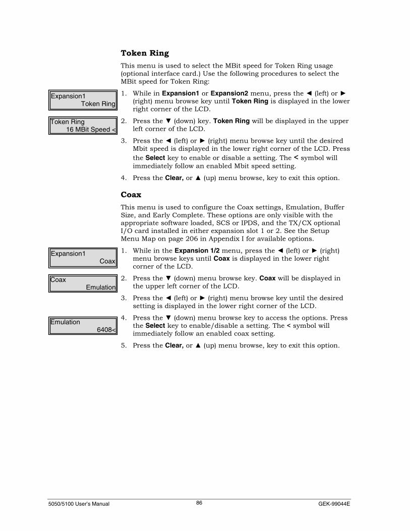
5050/5100 User’s Manual GEK-99044E86
Token RingThis menu is used to select the MBit speed for Token Ring usage(optional interface card.) Use the following procedures to select theMBit speed for Token Ring:
1. While in Expansion1 or Expansion2 menu, press the ◄ (left) or ►(right) menu browse key until Token Ring is displayed in the lowerright corner of the LCD.
2. Press the ▼ (down) key. Token Ring will be displayed in the upperleft corner of the LCD.
3. Press the ◄ (left) or ► (right) menu browse key until the desiredMbit speed is displayed in the lower right corner of the LCD. Pressthe Select key to enable or disable a setting. The < symbol willimmediately follow an enabled Mbit speed setting.
4. Press the Clear, or ▲ (up) menu browse, key to exit this option.
CoaxThis menu is used to configure the Coax settings, Emulation, BufferSize, and Early Complete. These options are only visible with theappropriate software loaded, SCS or IPDS, and the TX/CX optionalI/O card installed in either expansion slot 1 or 2. See the SetupMenu Map on page 206 in Appendix I for available options.
1. While in the Expansion 1/2 menu, press the ◄ (left) or ► (right)menu browse keys until Coax is displayed in the lower rightcorner of the LCD.
2. Press the ▼ (down) menu browse key. Coax will be displayed inthe upper left corner of the LCD.
3. Press the ◄ (left) or ► (right) menu browse key until the desiredsetting is displayed in the lower right corner of the LCD.
4. Press the ▼ (down) menu browse key to access the options. Pressthe Select key to enable/disable a setting. The < symbol willimmediately follow an enabled coax setting.
5. Press the Clear, or ▲ (up) menu browse, key to exit this option.
Expansion1Token Ring
Token Ring16 MBit Speed <
Expansion1Coax
CoaxEmulation
Emulation6408<

5050/5100 User’s Manual Chapter 5. Using the Setup Menu87
TwinaxThis menu is used to configure the Twinax settings, Emulation,Station Addr, and Buffer Size. These options are only visible with theappropriate software loaded, SCS or IPDS, and the TX/CX optionalI/O card installed in either expansion slot 1 or 2. See Setup MenuMap on page 206 in Appendix I for available options.
1. While in the Expansion 1/2 menu, press the ◄ (left) or ► (right)menu browse keys until Twinax is displayed in the lower rightcorner of the LCD.
2. Press the ▼ (down) menu browse key. Twinax will be displayed inthe upper left corner of the LCD.
3. Press the ◄ (left) or ► (right) menu browse key until the desiredsetting is displayed in the lower right corner of the LCD.
4. Press the ▼ (down) menu browse key to access the options. Pressthe Select key to enable/disable a setting. The < symbol willimmediately follow an enabled twinax setting.
5. Press the Clear, or ▲ (up) menu browse, key to exit this option.
Expansion1Twinax
TwinaxEmulation
Emulation6408<

5050/5100 User’s Manual GEK-99044E88
TCP/IPThis menu is used to configure the TCP/IP settings, IP Address,Netmask, Router IP Addr, and Frame Type. These options are user-specified, check with the network administrator where printer will beused.
Use the following procedures to set the TCP/IP settings:
1. While in the Expansion1 or Expansion2 menu, press the ◄ (left)or ► (right) menu browse key until TCP/IP is displayed in thelower right corner of the LCD.
2. Press the ▼ (down) menu browse key to access the TCP/IP menuoptions. TCP/IP is displayed in the upper left corner of the LCD.
3. Press the ◄ (left) or ► (right) menu browse key until the desiredmenu setting is displayed in the lower right corner of the LCD.Press the Select key to access the menu desired.
4. Press the Select key again to enable or disable a setting option.The < symbol will immediately follow an enabled TCP/IP setting.IP Address, Netmask, and Router IP Address are user set options.
5. Pressing the Clear key will exit the current option menu option, sothat selection of another option may be made.
Use the following procedures to use these settings:
1. The option to be set will be displayed in the upper right corner ofthe LCD. (The example to the left is for the IP Address setting.)Notice the cursor (underline) is now shown under the first digit.The horizontal ◄ ► (left or right) menu browse keys position thecursor (underline) under the digit to be changed; the vertical ▲ ▼(up or down) menu browse keys increment/decrement theselected digit by one.
2. Press the Clear key after all changes are complete and thedesired value is displayed in the lower right corner of the LCD.Pressing the Clear key does not erase the values entered, but doesallow the user to exit the User Set menu.
NoteRepeat this section if further changes are necessary. Cycle powerafter entries to activate changes.
Expansion1TCP/IP
TCP/IPIP Address
IP Address000.000.000.000

5050/5100 User’s Manual Chapter 5. Using the Setup Menu89
NetwareThis menu is used to select the Frame Type for Novell Netware Usethe following procedures to select a Frame Type for Netware.
1. While in the Expansion1 or Expansion2 menu, press the ◄ (left)or ► (right) menu browse key until Netware is displayed in thelower right corner of the LCD.
2. Press the ▼ (down) key. Netware will be displayed in the upperleft corner of the LCD and Frame Type will be displayed in thelower right corner.
3. Press the ▼ (down) key again. Frame Type will be displayed in theupper left corner of the LCD.
4. Press the ◄ (left) or ► (right) menu browse key until the desiredoption is displayed in the lower right corner of the LCD.
5. Press the Select key to enable or disable an option. The < symbolwill immediately follow an enabled option.
Expansion1Netware
NetwareFrame Type
Frame Type802.3 <

5050/5100 User’s Manual GEK-99044E90
IBM Host StatusIf enabled and an IBM interface board is installed in Expansion slot 1or 2, the control panel will display a status related to the IBM host.The messages are dependent on the connection type, Twinax or Coax.
ConnectionType LCD Message Meaning Action Required
Ready Printer is Online andcommunicating with the host. None
06 ATTENTION Operator attention is requestedby the host. See the system operator.Twinax
15 COMM CHECK No host communication. Check cabling.
Ready Printer is Online andcommunicating with the host. None.
06 ATTENTION Operation attention isrequested by the host.. See the system operator.
08 HOLD TIME-OUT
The printer is Offline and thetime set in menu options IRQBSY TO or IRQ ERR TO hasexpired.
Put the printer online.
27 NOT ENABLED Communications Failure. Check cabling.
28 NO CCUSIGNAL No host communication. Check cabling.
59 CANCELCancel requested. Will changeto “Ready” where cancel isaccepted by the host.
Put the printer online.
61 PA1PA1 key requested. Will changeto “Ready” when the key isaccepted by the host..
Put the printer online.
62 PA2PA2 key requested. Will changeto “Ready” when the key isaccepted by the host.
Put the printer online.
Coax
63 SEND STATE Printer placed in send state bythe host. See the system operator.
1. While in the I/F Settings menu, press the ◄ (left) or ► (right)menu browse key until IBM Host Status is located in the lowerright corner of the LCD.
2. Press the ▼ (down) menu browse, or the Select key, to access theIBM Host Status menu options.
3. Press the ◄ (left ) or ► (right) menu browse key until the desiredsetting is displayed in the lower right corner of the LCD.
4. Press the Select key to enable or disable an option. The < symbolwill immediately follow an enabled option.
IBM Host StatusEnable<
I/F SettingsIBM Host Status

5050/5100 User’s Manual Chapter 5. Using the Setup Menu91
SELECT FILTERThis menu option allows the operator to select an interface filteroption. Multiple filters can be active. Three software loads: standard,SCS, and IPDS (QMS and IGP is included in standard and SCSloads). The maximum multiple filters is four. Hexdump has thelowest selection priority.
Depending on the software that is loaded, the printer can processQMS, IGP, Coax/Twinax SCS and Coax/Twinax IPDS data. Allversions of software can process Hex Passtrough data. All versions ofsoftware can also execute Hex Dump mode, a diagnostic mode thatprints the received data as hex character pairs. Enabling a Filtercauses received data to be examined by that processor. For example,enabling the QMS Filter causes the received data to go through theQMS processor. If the QMS Filter is not enabled, the received data isnot examined by the QMS processor and any QMS commands in thedata will be print as text and not execute the QMS functionality.
Combinations of filters allows debugging received data and debuggingproblems with the printer’s processing of the received data. Thefollowing 4 examples describe the printer’s behavior with some of thefilter selections:
Example 1: Enabling the Hex Dump Filter causes the printer to printa hex dump of the data as it is received from the host. If the receiveddata is a coax or twinax, the dump is EBCDIC hex. Otherwise, it isASCII hex.
Example 2: Disabling the QMS Filter, will cause the printer to printQMS commands as normal text without the printer taking action onQMS commands received.
Example 3: Enabling the Hex Dump Filter and QMS simultaneously,will cause the printer to print a hex dump of the output of the QMSprocessor.
Example 4: Enabling the Hex Dump Filter and SCS simultaneously,will cause the printer to print a hex dump of the output of the SCSprocessor.

5050/5100 User’s Manual GEK-99044E92
The following table shows the order and printer function with variousFilter combinations:
Selection(s)IPDSor SCS
QMSor IGP
HexPass
HexDump
Action Taken by Printer
Printed without passing through any filter(s).
X Processed by the SCS or IPDS Filter.
X Processed by the QMS or IGP Filter.
X X Processed by the SCS or IPDS Filter first,then processed by the QMS or IGP Filter.
X Processed by the Hex Passthrough Filter.
X XProcessed by the SCS or IPDS Filter first,then processed by the Hex PassthroughFilter.
X X Processed by the QMS or IGP Filter first,then process by the Hex Passthrough Filter.
X X X
Processed by the SCS or IPDS Filter, thenprocessed by the QMS or IGP Filter, andfinally processed by the Hex PassthroughFilter.
X X Processed by the SCS or IPDS Filter first,then processed by the Hex Dump Filter.
X X Processed by the QMS or IGP Filter first,then processed by the Hex Dump Filter.
X X XProcessed by the SCS or IPDS Filter,processed by the QMS or IGP Filter, andfinally processed by the Hex Dump Filter.
X X Processed by the Hex Passthrough Filterfirst, then processed by the Hex Dump.
X X X
Processed by the SCS or IPDS Filter,processed by the Hex Passthrough Filter,and finally processed by the Hex DumpFilter.
X X X
Processed by the QMS or IGP Filter,processed by the Hex Passthrough Filter,and finally processed by the Hex DumpFilter.
X X X X
Processed by the SCS or IPDS Filter,processed by the QMS or IGP Filter,processed by the Hex Passthrough Filter andfinally processed by the Hex Dump Filter.
NoteQMS and IGP are mutually exclusive. Selecting the menu option“None” deactivates all interface filters. SCS and IPDS are onlyselectable if the optional SCS or IPDS software has been loaded.See the Operator Menu Map on page 204 in Appendix I for acomplete listing of the selections available.

5050/5100 User’s Manual Chapter 5. Using the Setup Menu93
1. While in Set Up menu, press the ◄ (left) or ► (right) menu browsekeys until Select Filter is displayed in the lower right corner of theLCD.
2. Press the ▼ (down) menu browse key to access the Select Filteroptions. Select Filter will be displayed in the upper left corner ofthe LCD.
3. Press the ◄ (left) or ► (right) menu browse keys until the filterdesired is displayed in the lower right corner of the LCD.
4. Press the Select key to select the filter option. The < symbol willnow immediately follow the saved filter option.
FILTER SETTINGSThis menu option configures settings for QMS, IGP, IPDS* and IBMFormat*.
Use the following procedures to use this option.
1. While in the Set Up menu, press the ◄ (left) or ► (right) menubrowse key until Filter Settings is displayed in the lower rightcorner of the LCD.
2. Press the ▼ (down) menu browse key to access the Filter Settingsoptions.
* Viewable with SCS or IPDS software installed in printer.
The following describes the sub-menus and options available:
IGPThis configures the IGP filter option.
1. While in the Filter Settings menu, press the ◄ (left) or ► (right)menu browse key until IGP is displayed in the lower right cornerof the display.
2. Press the ▼ (down) menu browse key to access the configurationsettings for IGP.
The following describes the options available:
BC DensityThis selects the BC (Bar Code) Density setting for IGP. Lowrepresents low density, Medium represents double horizontal, andHigh represents staggered format.
1. While in the IGP menu, press the ◄ (left) or ► (right) menubrowse key until BC Density is displayed in the lower right cornerof the LCD.
2. Press the ▼ (down) menu browse key to access the BC Densityoptions.
3. Press the ◄ (left) or ► (right) menu browse key until the desiredoption is displayed. Press the Select key to enable or disable anoption. The < symbol will immediately follow an enabled option.
Select FilterSerial
Set UpSelect Filter
Filter SettingsIGP
IGPBC Density
BC DensityHigh<
Set UpFilter Settings
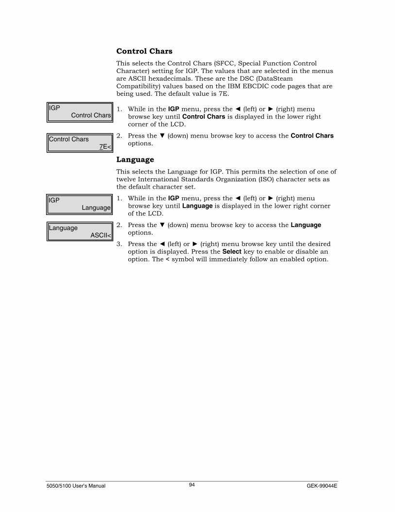
5050/5100 User’s Manual GEK-99044E94
Control CharsThis selects the Control Chars (SFCC, Special Function ControlCharacter) setting for IGP. The values that are selected in the menusare ASCII hexadecimals. These are the DSC (DataSteamCompatibility) values based on the IBM EBCDIC code pages that arebeing used. The default value is 7E.
1. While in the IGP menu, press the ◄ (left) or ► (right) menubrowse key until Control Chars is displayed in the lower rightcorner of the LCD.
2. Press the ▼ (down) menu browse key to access the Control Charsoptions.
LanguageThis selects the Language for IGP. This permits the selection of one oftwelve International Standards Organization (ISO) character sets asthe default character set.
1. While in the IGP menu, press the ◄ (left) or ► (right) menubrowse key until Language is displayed in the lower right cornerof the LCD.
2. Press the ▼ (down) menu browse key to access the Languageoptions.
3. Press the ◄ (left) or ► (right) menu browse key until the desiredoption is displayed. Press the Select key to enable or disable anoption. The < symbol will immediately follow an enabled option.
IGPControl Chars
Control Chars7E<
IGPLanguage
LanguageASCII<

5050/5100 User’s Manual Chapter 5. Using the Setup Menu95
IGP TerminatorThis selects the IGP Terminator for IGP. When set to CR, all IGPcommands are required to be terminated with a carriage return.When set to CR LF, all IGP commands are required to be terminatedwith a carriage return and linefeed.
1. While in the IGP menu, press the ◄ (left) or ► (right) menubrowse key until IGP Terminator is displayed in the lower rightcorner of the LCD.
2. Press the ▼ (down) menu browse key to access the IGPTerminator options.
3. Press the ◄ (left) or ► (right) menu browse key until the desiredoption is displayed. Press the Select key to enable or disable anoption. The < symbol will immediately follow an enabled option.
Quiet ModeThis selects the Quiet Mode setting for IGP. When enabled, all IGPcommands are passed unprocessed to the printer (printed as text.)Disabling this option, or receiving a LISTEN command, will disableQuiet Mode.
1. While in the IGP menu, press the ◄ (left) or ► (right) menubrowse key until Quiet Mode is displayed in the lower right cornerof the LCD.
2. Press the ▼ (down) menu browse key to access the Quiet Modeoptions.
3. Press the ◄ (left) or ► (right) menu browse key until the desiredoption is displayed. Press the Select key to enable or disable anoption. The < symbol will immediately follow an enabled option.
Delete LogosThis selects the Delete Logos setting for IGP. When enabled, logosthat are associated with a form will be deleted when the form isdeleted. To conserve IGP memory, all forms and logos should bedeleted when they are no longer required.
1. While in the IGP menu, press the ◄ (left) or ► (right) menubrowse key until Delete Logos is displayed in the lower rightcorner of the LCD.
2. Press the ▼ (down) menu browse key to access the Delete Logosoptions.
3. Press the ◄ (left) or ► (right) menu browse key until the desiredoption is displayed. Press the Select key to enable or disable anoption. The < symbol will immediately follow an enabled option.
IGPQuiet Mode
IGPIGP Terminator
IGPDelete Logos
IGP TerminatorCR LF<
Quiet ModeDisable<
Delete LogosDisable<

5050/5100 User’s Manual GEK-99044E96
Default OCR-BThis selects the OCR-B setting for IGP. When enabled, the defaultfont will be OCR-B.
1. While in the IGP menu, press the ◄ (left) or ► (right) menubrowse key until Default OCR-B is displayed in the lower rightcorner of the LCD.
2. Press the ▼ (down) menu browse key to access the Default OCR-Boptions.
3. Press the ◄ (left) or ► (right) menu browse key until the desiredoption is displayed. Press the Select key to enable or disable anoption. The < symbol will immediately follow an enabled option.
Vertical DPIThis selects the Vertical DPI setting for IGP. This is used to specifythe Vertical Dots Per Inch. If set to 70 (72), a one-inch (1”) highcharacter will be 70 (72) of an inch high.
1. While in the IGP menu, press the ◄ (left) or ► (right) menubrowse key until Vertical DPI is displayed in the lower right cornerof the LCD.
2. Press the ▼ (down) menu browse key to access the Vertical DPIoptions.
3. Press the ◄ (left) or ► (right) menu browse key until the desiredoption is displayed. Press the Select key to enable or disable anoption. The < symbol will immediately follow an enabled option.
Slashed ZeroThis selects the Slashed Zero setting for IGP. When enabled, zerocharacters will print as slashed zeros, e.g.. “Ø.”
1. While in the IGP menu, press the ◄ (left) or ► (right) menubrowse key until Slashed Zero is displayed in the lower rightcorner of the LCD.
2. Press the ▼ (down) menu browse key to access the Slashed Zerooptions.
3. Press the ◄ (left) or ► (right) menu browse key until the desiredoption is displayed. Press the Select key to enable or disable anoption. The < symbol will immediately follow an enabled option.
IGPVertical DPI
IGPDefault OCR-B
IGPSlashed Zero
Default OCR-BDisable<
Vertical DPI72<
Slashed ZeroDisable<

5050/5100 User’s Manual Chapter 5. Using the Setup Menu97
Clip TextThis selects the Clip Text (Excess Text Ignored) setting for IGP. Whenenabled, any text that exceeds the IGP form length will not beprinted.
1. While in the IGP menu, press the ◄ (left) or ► (right) menubrowse key until Clip Text is displayed in the lower right corner ofthe LCD.
2. Press the ▼ (down) menu browse key to access the Clip Textoptions.
3. Press the ◄ (left) or ► (right) menu browse key until the desiredoption is displayed. Press the Select key to enable or disable anoption. The < symbol will immediately follow an enabled option.
Ignore Chr ModeThis menu selects the Ignore Character Mode setting for IGP. WhenIgnore Chr Mode is enabled, the character value specified in IgnoreChar option will be discarded when detected in the datastream. If thisoption is enabled, a character must be designated to be discardedusing an Ignore Char (see next option.)
1. While in the IGP menu, press the ◄ (left) or ► (right) menubrowse key until Ignore Chr Mode is displayed in the lower rightcorner of the LCD.
2. Press the ▼ (down) menu browse key to access the Ignore ChrMode options.
3. Press the ◄ (left) or ► (right) menu browse key until the desiredoption is displayed. Press the Select key to enable or disable anoption. The < symbol will immediately follow an enabled option.
IGPClip Text
Clip TextDisable<
Ignore Chr ModeDisable<
IGPIgnore Chr Mode

5050/5100 User’s Manual GEK-99044E98
Ignore CharThis menu option is used to set the hexadecimal value of the receiveddata character to be ignored when the Ignore Chr Mode is enabled(See previous option). The valid range of hexadecimal values is 0X00to 0XFF.
Use the following procedure to select this option:
1. While in the IGP menu, press the ◄ (left) or ► (right) menubrowse key until Ignore Character is displayed in the lower rightcorner of the LCD.
2. Press the Select key to access the Ignore Character options.
3. This option is user set. Notice the cursor (underline) is nowshown under the first digit. The horizontal ◄ ► (left or right)menu browse keys to position the cursor (underline) under thedigit to be changed; the vertical ▲ ▼ (up or down) menu browsekey increment/decrement the selected alphanumeric digit by one.Enter the hex value of the character desired.
4. Press the Select key after all changes are complete and thedesired value is displayed in the lower right corner of the LCD.Repeat this step if further changes are necessary.
5. Press the Clear key to exit this option.
Form Length=0With Normal enabled, the printer will logically advance by the <FF>command after processing an execution command. This is the defaultfactory-set condition. The user may set this option to Ignore and theprinter will not logically advance by the <FF> command.
1. While in the IGP menu, press the ◄ (left) or ► (right) menubrowse key until Form Length=0 is displayed in the lower rightcorner of the LCD.
2. Press the ▼ (down) menu browse key to access the FormLength=0 options.
3. Press the ◄ (left) or ► (right) menu browse key until the desiredoption is displayed. Press the Select key to enable or disable anoption. The < symbol will immediately follow an enabled option.
IGPIgnore Char
Ignore Char00
Form Length=0Normal<
IGPForm Length=0
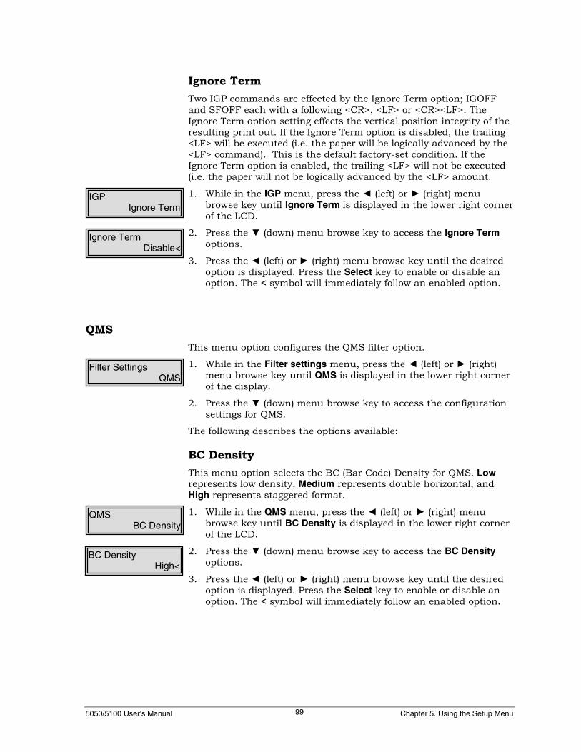
5050/5100 User’s Manual Chapter 5. Using the Setup Menu99
Ignore TermTwo IGP commands are effected by the Ignore Term option; IGOFFand SFOFF each with a following <CR>, <LF> or <CR><LF>. TheIgnore Term option setting effects the vertical position integrity of theresulting print out. If the Ignore Term option is disabled, the trailing<LF> will be executed (i.e. the paper will be logically advanced by the<LF> command). This is the default factory-set condition. If theIgnore Term option is enabled, the trailing <LF> will not be executed(i.e. the paper will not be logically advanced by the <LF> amount.
1. While in the IGP menu, press the ◄ (left) or ► (right) menubrowse key until Ignore Term is displayed in the lower right cornerof the LCD.
2. Press the ▼ (down) menu browse key to access the Ignore Termoptions.
3. Press the ◄ (left) or ► (right) menu browse key until the desiredoption is displayed. Press the Select key to enable or disable anoption. The < symbol will immediately follow an enabled option.
QMSThis menu option configures the QMS filter option.
1. While in the Filter settings menu, press the ◄ (left) or ► (right)menu browse key until QMS is displayed in the lower right cornerof the display.
2. Press the ▼ (down) menu browse key to access the configurationsettings for QMS.
The following describes the options available:
BC DensityThis menu option selects the BC (Bar Code) Density for QMS. Lowrepresents low density, Medium represents double horizontal, andHigh represents staggered format.
1. While in the QMS menu, press the ◄ (left) or ► (right) menubrowse key until BC Density is displayed in the lower right cornerof the LCD.
2. Press the ▼ (down) menu browse key to access the BC Densityoptions.
3. Press the ◄ (left) or ► (right) menu browse key until the desiredoption is displayed. Press the Select key to enable or disable anoption. The < symbol will immediately follow an enabled option.
Filter SettingsQMS
QMSBC Density
BC DensityHigh<
Ignore TermDisable<
IGPIgnore Term

5050/5100 User’s Manual GEK-99044E100
Control CharsThe values that are selected in the menus are ASCII hexadecimals.These are the DSC (DataSteam Compatibility) values based on theIBM EBCDIC code pages that are being used. The default is 0X5E(cirumflex).
1. While in the QMS menu, press the ◄ (left) or ► (right) menubrowse key until Control Chars is displayed in the lower rightcorner of the LCD.
2. Press the ▼ (down) menu browse key to access the Control Charsoptions.
LanguageThis menu option selects the Language for QMS. This permits theselection of one of twelve International Standards Organization (ISO)character sets as the default character set.
1. While in the QMS menu, press the ◄ (left) or ► (right) menubrowse key until Language is displayed in the lower right cornerof the LCD.
2. Press the ▼ (down) menu browse key to access the Languageoptions.
3. Press the ◄ (left) or ► (right) menu browse key until the desiredoption is displayed. Press the Select key to enable or disable anoption. The < symbol will immediately follow an enabled option.
QMSControl Chars
Control Chars5E<
QMSLanguage
LanguageEnglish (USA)<

5050/5100 User’s Manual Chapter 5. Using the Setup Menu101
Code VWhen this feature is enabled, QMS commands will be processed asthough a ^PY (QMS ON) Command had been received. This feature isused in installations where all jobs do not contain the ^PYCommand. With this feature enabled, the printer is always in the“QMS ON” mode.
1. While in the QMS menu, press the ◄ (left) or ► (right) menubrowse key until Code V is displayed in the lower right corner ofthe LCD.
2. Press the ▼ (down) menu browse key to access the Code Voptions.
3. Press the ◄ (left) or ► (right) menu browse key until the desiredoption is displayed. Press the Select key to enable or disable anoption. The < symbol will immediately follow an enabled option.
Free FormatThis menu selects Free Format setting for QMS. If enabled, theprinter ignores all characters with hexadecimal values less than 20H,this includes all system paper movement commands. This option willbe turned off if the printer receives the ^O (Free Format OFF)Command.
1. While in the QMS menu, press the ◄ (left) or ► (right) menubrowse key until Free Format is displayed in the lower right cornerof the LCD.
2. Press the ▼ (down) menu browse key to access the Free Formatoptions.
3. Press the ◄ (left) or ► (right) menu browse key until the desiredoption is displayed. Press the Select key to enable or disable anoption. The < symbol will immediately follow an enabled option.
Ignore ModeThis selects Ignore Mode (Ignore Data Mode) for QMS. When IgnoreMode is enabled, all data received from the host is ignored until a ^A(Ignore Mode OFF) Command is received. If this option is enabled, theCode V option must also be enabled.
1. While in the QMS menu, press the ◄ (left) or ► (right) menubrowse key until Ignore Default is displayed in the lower rightcorner of the LCD.
2. Press the ▼ (down) menu browse key to access the Ignore Defaultoptions.
3. Press the ◄ (left) or ► (right) menu browse key until the desiredoption is displayed. Press the Select key to enable or disable anoption. The < symbol will immediately follow an enabled option.
Code VDisable<
QMSCode V
Free FormatDisable<
QMSFree Format
Ignore ModeDisable<
QMSIgnore Mode

5050/5100 User’s Manual GEK-99044E102
Slashed ZeroThis selects the Slashed Zero setting for QMS. When enabled, zerosare printed as slashed zeros, e.g.. “Ø.”
1. While in the QMS menu, press the ◄ (left) or ► (right) menubrowse key until Slashed Zero is displayed in the lower rightcorner of the LCD.
2. Press the ▼ (down) menu browse key to access the Slashed Zerooptions.
3. Press the ◄ (left) or ► (right) menu browse key until the desiredoption is displayed. Press the Select key to enable or disable anoption. The < symbol will immediately follow an enabled option.
PY TerminatorThis selects either CR or CR LF as the ^PY Command Terminator forQMS. The ^PY^- magnum on command should be terminated withASCII <CR><LF>. With this option set to LF, the <LF> is ignored. Itmay also be terminated by a carriage return/linefeed combination.The linefeed causes printing to begin on the second line of theprogram. If printing on the first line is desired, set this option to CR.
1. While in the QMS menu, press the ◄ (left) or ► (right) menubrowse key until PY Terminator is displayed in the lower rightcorner of the LCD.
2. Press the ▼ (down) menu browse key to access the PY Terminatoroptions.
3. Press the ◄ (left) or ► (right) menu browse key until the desiredoption is displayed. Press the Select key to enable or disable anoption. The < symbol will immediately follow an enabled option.
PN TerminatorThis selects either CR or CR LF as the ^PN Command Terminator forQMS. The QMS OFF Command ^PN^- may be terminated by acarriage return/linefeed combination. If no linefeed is desired whenQMS is turned off, set this option to CR.
1. While in the QMS menu, press the ◄ (left) or ► (right) menubrowse key until PN Terminator is displayed in the lower rightcorner of the LCD.
2. Press the ▼ (down) menu browse key to access the PN Terminatoroptions.
3. Press the ◄ (left) or ► (right) menu browse key until the desiredoption is displayed. Press the Select key to enable or disable anoption. The < symbol will immediately follow an enabled option.
Slashed ZeroDisable<
QMSSlashed Zero
PY TerminatorCR<
QMSPY Terminator
PN TerminatorCR<
QMSPN Terminator

5050/5100 User’s Manual Chapter 5. Using the Setup Menu103
Vertical DPIThis menu selects the Vertical DPI setting for QMS. This specifies theVertical Dots Per Inch in Code V Version I. If set to 70 (72), a one-inch (1”) high character (as called for in a Magnum command) will be70(72) of an inch high.
1. While in the QMS menu, press the ◄ (left) or ► (right) menubrowse key until Vertical DPI is displayed in the lower right cornerof the LCD.
2. Press the ▼ (down) menu browse key to access the Vertical DPIoptions.
3. Press the ◄ (left) or ► (right) menu browse key until the desiredoption is displayed. Press the Select key to enable or disable anoption. The < symbol will immediately follow an enabled option.
LPI GridThis menu selects the LPI Grid setting for QMS. When enabled, alinefeed <LF> after a graphics pass position printing at the next LPIgrid position. If disabled, a linefeed after a graphics move will movethe paper a full LPI increment.
Use the following procedure to select this option:
1. While in the QMS menu, press the ◄ (left) or ► (right) menubrowse key until LPI Grid is displayed in the lower right corner ofthe LCD.
2. Press the ▼ (down) menu browse key to access the LPI Gridoptions.
3. Press the ◄ (left) or ► (right) menu browse key until the desiredoption is displayed. Press the Select key to enable or disable anoption. The < symbol will immediately follow an enabled option.
VersionThis menu selects the Version for QMS. This feature is provided forusers of Code V Version I programming which utilized rotatedMAGNUM characters. Elongation of characters could cause print linelength to be exceeded. Setting this option to Ver I, will preventcharacter elongation from causing print line overflow.
1. While in the QMS menu, press the ◄ (left) or ► (right) menubrowse key until Version is displayed in the lower right corner ofthe LCD.
2. Press the ▼ (down) menu browse key to access the Versionoptions.
3. Press the ◄ (left) or ► (right) menu browse key until the desiredoption is displayed. Press the Select key to enable or disable anoption. The < symbol will immediately follow an enabled option.
Vertical DPI72<
QMSVertical DPI
LPI GridDisable<
QMSLPI Grid
VersionVer I<
QMSVersion

5050/5100 User’s Manual GEK-99044E104
Magnum SpacesThis selects Magnum Spaces for QMS. When Magnum Spaces isenabled, trailing spaces in strings are ignored. If a Magnum pass fieldcontains only spaces, the defined height of the field is ignored.
1. While in the QMS menu, press the ◄ (left) or ► (right) menubrowse key until Magnum Spaces is displayed in the lower rightcorner of the LCD.
2. Press the ▼ (down) menu browse key to access the MagnumSpaces options.
3. Press the ◄ (left) or ► (right) menu browse key until the desiredoption is displayed. Press the Select key to enable or disable anoption. The < symbol will immediately follow an enabled option.
Ignore Chr ModeThis menu selects the Ignore Character Mode setting for QMS. WhenIgnore Chr Mode is enabled, the character value specified in IgnoreChar option will be discarded when detected in the datastream. If thisoption is enabled, a character must be designated to be discardedusing the Ignore Char (see next option.)
1. While in the QMS menu, press the ◄ (left) or ► (right) menubrowse key until Ignore Chr Mode is displayed in the lower rightcorner of the LCD.
2. Press the ▼ (down) menu browse key to access the Ignore ChrMode options.
3. Press the ◄ (left) or ► (right) menu browse key until the desiredoption is displayed. Press the Select key to enable or disable anoption. The < symbol will immediately follow an enabled option.
VersionDisable<
QMSMagnum Spaces
Ignore Chr ModeDisable<
QMSIgnore Chr Mode
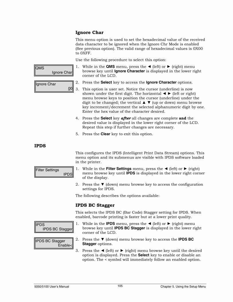
5050/5100 User’s Manual Chapter 5. Using the Setup Menu105
Ignore CharThis menu option is used to set the hexadecimal value of the receiveddata character to be ignored when the Ignore Chr Mode is enabled(See previous option). The valid range of hexadecimal values is 0X00to 0XFF.
Use the following procedure to select this option:
1. While in the QMS menu, press the ◄ (left) or ► (right) menubrowse key until Ignore Character is displayed in the lower rightcorner of the LCD.
2. Press the Select key to access the Ignore Character options.
3. This option is user set. Notice the cursor (underline) is nowshown under the first digit. The horizontal ◄ ► (left or right)menu browse keys to position the cursor (underline) under thedigit to be changed; the vertical ▲ ▼ (up or down) menu browsekey increment/decrement the selected alphanumeric digit by one.Enter the hex value of the character desired.
4. Press the Select key after all changes are complete and thedesired value is displayed in the lower right corner of the LCD.Repeat this step if further changes are necessary.
5. Press the Clear key to exit this option.
IPDSThis configures the IPDS (Intelligent Print Data Stream) options. Thismenu option and its submenus are visible with IPDS software loadedin the printer.
1. While in the Filter Settings menu, press the ◄ (left) or ► (right)menu browse key until IPDS is displayed in the lower right cornerof the display.
2. Press the ▼ (down) menu browse key to access the configurationsettings for IPDS.
The following describes the options available:
IPDS BC StaggerThis selects the IPDS BC (Bar Code) Stagger setting for IPDS. Whenenabled, barcode printing is faster but at a lower print quality.
1. While in the IPDS menu, press the ◄ (left) or ► (right) menubrowse key until IPDS BC Stagger is displayed in the lower rightcorner of the LCD.
2. Press the ▼ (down) menu browse key to access the IPDS BCStagger options.
3. Press the ◄ (left) or ► (right) menu browse key until the desiredoption is displayed. Press the Select key to enable or disable anoption. The < symbol will immediately follow an enabled option.
QMSIgnore Char
Ignore Char00
Filter SettingsIPDS
IPDSIPDS BC Stagger
IPDS BC StaggerEnable<

5050/5100 User’s Manual GEK-99044E106
IPDS BC DensityThis selects the IPDS BC (Barcode) Density setting for IPDS. Low is72 dots horizontally by 72 dots vertically and High is 144 dotshorizontally by 144 vertically.
1. While in the IPDS menu, press the ◄ (left) or ► (right) menubrowse key until IPDS BC Density is displayed in the lower rightcorner of the LCD.
2. Press the ▼ (down) menu browse key to access the IPDS BCDensity options.
3. Press the ◄ (left) or ► (right) menu browse key until the desiredoption is displayed. Press the Select key to enable or disable anoption. The < symbol will immediately follow an enabled option.
Note
At Low density, some barcode styles may not be readable.
IPDS GR DensityThis selects the IPDS GR (Graphics) Density setting for IPDS. Low is72 dots per inch and High is 144 dots per inch. Higher density meansbetter print quality, but at a lower speed.
1. While in the IPDS menu, press the ◄ (left) or ► (right) menubrowse key until IPDS GR Density is displayed in the lower rightcorner of the LCD.
2. Press the ▼ (down) menu browse key to access the IPDS GRDensity options.
3. Press the ◄ (left) or ► (right) menu browse key until the desiredoption is displayed. Press the Select key to enable or disable anoption. The < symbol will immediately follow an enabled option.
IPDS Im DensityThis selects the IPDS Im (Image) Density setting for IPDS. Low is 72dots per inch and High is 144 dots per inch. Higher density meansbetter print quality, but at a lower speed.
1. While in the IPDS menu, press the ◄ (left) or ► (right) menubrowse key until IPDS Image Density is displayed in the lowerright corner of the LCD.
2. Press the ▼ (down) menu browse key to access the IPDS ImageDensity options.
3. Press the ◄ (left) or ► (right) menu browse key until the desiredoption is displayed. Press the Select key to enable or disable anoption. The < symbol will immediately follow an enabled option.
IPDSIPDS BC Density
IPDS BC DensityLow<
IPDSIPDS GR Density
IPDS GR DensityLow<
IPDSIPDS Image Density
IPDS Image DensityLow<

5050/5100 User’s Manual Chapter 5. Using the Setup Menu107
IPDS TextThis selects the IPDS Text Quality. Dp (Data Processing), Draft andNLQ (Near Letter Quality) are the options available.
1. While in the IPDS menu, press the ◄ (left) or ► (right) menubrowse key until IPDS Text is displayed in the lower right cornerof the LCD.
2. Press the ▼ (down) menu browse key to access the IPDS Textoptions.
3. Press the ◄ (left) or ► (right) menu browse key until the desiredoption is displayed. Press the Select key to enable or disable anoption. The < symbol will immediately follow an enabled option.
IPDS Dens OvrThis selects IPDS Dens Ovr (Density Override) setting for IPDS. Whenenabled, the printer will override any IPDS command attempting tochange the IPDS BC Density, IPDS GR Density, IPDS Image Density,and IPDS Text quality, the current menu values are used. Whendisabled, densityand text quality values can be changed by IPDScommands.
1. While in the IPDS menu, press the ◄ (left) or ► (right) menubrowse key until IPDS Dens Ovr is displayed in the lower rightcorner of the LCD.
2. Press the ▼ (down) menu browse key to access the IPDS Dens Ovroptions.
3. Press the ◄ (left) or ► (right) menu browse key until the desiredoption is displayed. Press the Select key to enable or disable anoption. The < symbol will immediately follow an enabled option.
IBM FormatThis configures the settings in the IBM Format menu. The menu andits submenus are only visible with IPDS or SCS software loaded inthe printer. Some of these options apply only to SCS and some applyto both SCS and IPDS.
1. While in the Filter Settings menu, press the ◄ (left) or ► (right)menu browse key until IBM Format is displayed in the lower rightcorner of the display.
2. Press the ▼ (down) menu browse key to access the configurationsettings for IBM Format.
The following describes the options available:
IPDSIPDS Dens Ovr
IPDS Dens OvrDisable<
IPDSIPDS Text
IPDS TextDisable<
Filter SettingsIBM Format

5050/5100 User’s Manual GEK-99044E108
Code PageThis selects the EBDIC Code Page for SCS and IPDS. See the Set UpMenu Map on page 207 in Appendix I for a complete listing ofavailable selections.
1. While in the IBM Format menu, press the ◄ (left) or ► (right)menu browse key until Code Page is displayed in the lower rightcorner of the LCD.
2. Press the ▼ (down) menu browse key to access the Code Pageoptions.
3. Press the ◄ (left) or ► (right) menu browse key until the desiredoption is displayed. Press the Select key to enable or disable anoption. The < symbol will immediately follow an enabled option.
Code Pg OverrideThis is used to enable/disable Code Page Override. When enabled,the printer will override any host-set command which attempts tochange the Code Page. The current menu selection is used.
1. While in the IBM Format menu, press the ◄ (left) or ► (right)menu browse key until Code Pg Override is displayed in the lowerright corner of the LCD.
2. Press the ▼ (down) menu browse key to access the Code PgOverride options.
3. Press the ◄ (left) or ► (right) menu browse key until the desiredoption is displayed. Press the key to enable or disable an option.The < symbol will immediately follow an enabled option.
Draft = High SpeedIf an SCS or IPDS command is received that defines Draft font andthis option is disabled, the Draft font (standard 7 dot rows high) isselected. If Draft is requested and this option is enabled, the HighSpeed Draft font (5 dot rows high) is selected.
NoteHigh Speed greatly improves throughput, but not all charactersrequired by all IBM Code Pages are available.
1. While in the IBM Format menu option, press the ◄ (left) or ►(right) key until Draft = High Speed is displayed in the lower rightcorner of the LCD.
2. Press the ▼ (down) key to access the Draft = High Speed menuoptions.
3. Press the ◄ (left) or ► (right) menu browse key until the desiredoption is displayed. Press the Select key to enable or disable anoption. The < symbol will immediately follow an enabled option.
IBM FormatCode Page
Code Page037<
IBM FormatCode Pg Override
Code Pg OverrideDisable<
IBM FormatDraft = High Speed
Draft = High SpeedDisable<

5050/5100 User’s Manual Chapter 5. Using the Setup Menu109
LPIThis changes the operator-set LPI (Lines Per Inch) in DSC/DSE mode,this value cannot be overridden by the host. The operator-set LPIvalue can be changed by the SCS datastream.
1. While in the IBM Format menu option, press the ◄ (left) or ►(right) key until LPI is displayed in the lower right corner of theLCD.
2. Press the ▼ (down) key to access the LPI menu options.
3. Press the ◄ (left) or ► (right) menu browse key until the desiredoption is displayed. Press the Select key to enable or disable anoption. The < symbol will immediately follow an enabled option.
LPI OverrideThis enables/disables the LPI Override setting. When enabled, theprinter will override (ignore) any host-SCS command which attemptsto change the lines per inch value. The current operator-set value isused.
1. While in the IBM Format menu option, press the ◄ (left) or ►(right) key until LPI Override is displayed in the lower right cornerof the LCD.
2. Press the ▼ (down) key to access the LPI Override menu options.
3. Press the ◄ (left) or ► (right) menu browse key until the desiredoption is displayed. Press the Select key to enable or disable anoption. The < symbol will immediately follow an enabled option.
CPIThis changes the operator-set CPI (Characters Per Inch). Theoperator-set CPI value can be overridden by the datastream. InDCS/DSE mode, this value cannot be overridden by the host.
1. While in the IBM Format menu option, press the ◄ (left) or ►(right) key until CPI is displayed in the lower right corner of theLCD.
2. Press the ▼ (down) key to access the CPI menu options.
3. Press the ◄ (left) or ► (right) menu browse key until the desiredoption is displayed. Press the Select key to enable or disable anoption. The < symbol will immediately follow an enabled option.
IBM FormatLPI Override
LPI OverrideDisable<
IBM FormatLPI
LPI6<
IBM FormatCPI
CPI10<

5050/5100 User’s Manual GEK-99044E110
CPI OverrideThis enables/disables the CPI Override setting. When enabled, theprinter will override (ignore) any host-SCS command which attemptsto change the characters per inch value. The current operator-setvalue will be used.
1. While in the IBM Format menu option, press the ◄ (left) or ►(right) menu browse key until CPI Override is displayed in thelower right corner of the LCD.
2. Press the ▼ (down) menu browse key to access the CPI Overrideoptions.
3. Press the ◄ (left) or ► (right) menu browse key until the desiredoption is displayed. Press the Select key to enable or disable anoption. The < symbol will immediately follow an enabled option.
MPPMPP sets the value for the maximum print position. In SCS mode,this value may be overridden by host-SCS commands. When poweredon, the printer computes the available MPP. If this option is set tozero or a value greater than the computed maximum, the printer willuse the computed maximum as the default. In DSC/DSE, mode thisvalue cannot be overridden by the host.
1. While in the IBM Format menu, press the ◄ (left) or ► (right)menu browse key until MPP is displayed in the lower right cornerof the LCD.
2. Press the Select key to configure the MPP options.
3. Notice the cursor (underline) is now shown under the first digit.Use the horizontal ◄ ► (left or right) menu browse keys toposition the cursor (underline) under the digit to be changes; usethe vertical ▲ ▼ (up or down) menu browse keys toincrement/decrement the selected numeric digit by one.
4. Press the Clear key after all changes are complete and thedesired value is displayed in the lower right corner of the LCD.
Note
Repeat this section if further changes are necessary.
IBM FormatCPI Override
CPI OverrideDisable<
IBM FormatMPP
MPP000

5050/5100 User’s Manual Chapter 5. Using the Setup Menu111
MPP OverrideThis enables/disables MPP (maximum print position) Override. Whenenabled, the printer will override (ignore) any host-SCS commandwhich attempts to change MPP. The operator-set value is used.
1. While in the IBM Format menu, press the ◄ (left) or ► (right)menu browse key until MPP Override is displayed in the lowerright corner of the LCD.
2. Press the ▼ (down) menu browse key to access the MPP Overrideoptions.
3. Press the ◄ (left) or ► (right) menu browse key until the desiredoption is displayed. Press the Select key to enable or disable anoption. The < symbol will immediately follow an enabled option.
MPLMPL sets the value for the default maximum page length in lines. InSCS mode this value may be overridden by the host-SCS command.When powered on, the printer computes the available page length. Ifthe MPL is set to zero or a value greater than the computedmaximum, the printer will use the computed maximum as thedefault. In DSC/DSE mode, this option sets the absolute MPL andcannot be overridden by the data stream.
1. While in the IBM Format menu, press the ◄ (left) or ► (right)menu browse key until MPL is displayed in the lower right cornerof the LCD.
2. Press the Select key to configure the MPL options.
3. Notice the cursor (underline) is now shown under the first digit.Use the horizontal ◄ ► (left or right) menu browse keys toposition the cursor (underline) under the digit to be changes; usethe vertical ▲ ▼ (up or down) menu browse keys toincrement/decrement the selected numeric digit by one.
4. Press the Clear key after all changes are complete and thedesired value is displayed in the lower right corner of the LCD.
Note
Repeat this section if further changes are necessary.
IBM FormatMMP Override
MMP OverrideDisable<
IBM FormatMPL
MPL000

5050/5100 User’s Manual GEK-99044E112
MPL OverrideThis enables/disables MPL (maximum print lines) Override. Whenenabled, the printer will override (ignore) any host-SCS commandwhich attempts to change MPL.
4. While in the IBM Format menu, press the ◄ (left) or ► (right)menu browse key until MPL Override is displayed in the lowerright corner of the LCD.
5. Press the ▼ (down) menu browse key to access the MPL Overrideoptions.
6. Press the ◄ (left) or ► (right) menu browse key until the desiredoption is displayed. Press the Select key to enable or disable anoption. The < symbol will immediately follow an enabled option.
SCS TextThis selects text quality for SCS mode. The options (ranked fromlowest quality to highest quality are Draft, Data Processing, and NearLetter Quality.
1. While in the IBM Format menu, press the ◄ (left) or ► (right)menu browse key until SCS Text is displayed in the lower rightcorner of the LCD.
2. Press the ▼ (down) menu browse key to access the SCS Textoptions.
3. Press the ◄ (left) or ► (right) menu browse key until the desiredoption is displayed. Press the Select key to enable or disable anoption. The < symbol will immediately follow an enabled option.
Override TextThis enables/disables the Override Text option. When enabled, theprinter will override (ignore) any host-SCS command which attemptsto change the text quality selected by the SCS text menu. Theoperator-set value will be used.
1. While in the IBM Format menu, press the ◄ (left) or ► (right)menu browse key, until Override Text is displayed in the lowerright corner of the LCD.
2. Press the ▼ (down) menu browse key to access the Override Textoptions.
3. Press the ◄ (left) or ► (right) menu browse key until the desiredoption is displayed. Press the Select key to enable or disable anoption. The < symbol will immediately follow an enabled option.
IBM FormatMPL Override
MPL OverrideDisable<
IBM FormatOverride Text
Override TextDisable
IBM FormatSCS Text
SCS TextDp<

5050/5100 User’s Manual Chapter 5. Using the Setup Menu113
Override AllThis enables/disables the Override All option. When enabled, theprinter will override (ignore) any host-SCS commands which attemptsto change the values of Code Page, LPI, CPI, MPP, or MPL. Operator-set values will be used. When disabled, the individual overrideoptions control Code Page, LPI, CPI, MPP, or MPL.
1. While in the IBM Format menu, press the ◄ (left) or ► (right)menu browse key until Override All is displayed in the lower rightcorner of the LCD.
2. Press the ▼ (down) menu browse key to access the Override MMPoptions.
3. Press the ◄ (left) or ► (right) menu browse key until the desiredoption is displayed. Press the Select key to enable or disable anoption. The < symbol will immediately follow an enabled option.
Hex PrintThis enables/disables the Hex Print option. Hex Print is used totroubleshoot communications or applications program problems. Thereceived EBCDIC data stream is converted to hex dump format andprinted. The printout can aid in determining what the printer is beinginstructed to do by the data stream.
1. While in the IBM Format menu, press the ◄ (left) or ► (right)menu browse key until Hex Print is displayed in the lower rightcorner of the LCD.
2. Press the ▼ (down) menu browse key to access the Hex Printoptions.
3. Press the ◄ (left) or ► (right) menu browse key until the desiredoption is displayed. Press the Select key to enable or disable anoption. The < symbol will immediately follow an enabled option.
IBM FormatOverride All
Override AllDisable<
IBM FormatHex Print
Hex PrintDisable
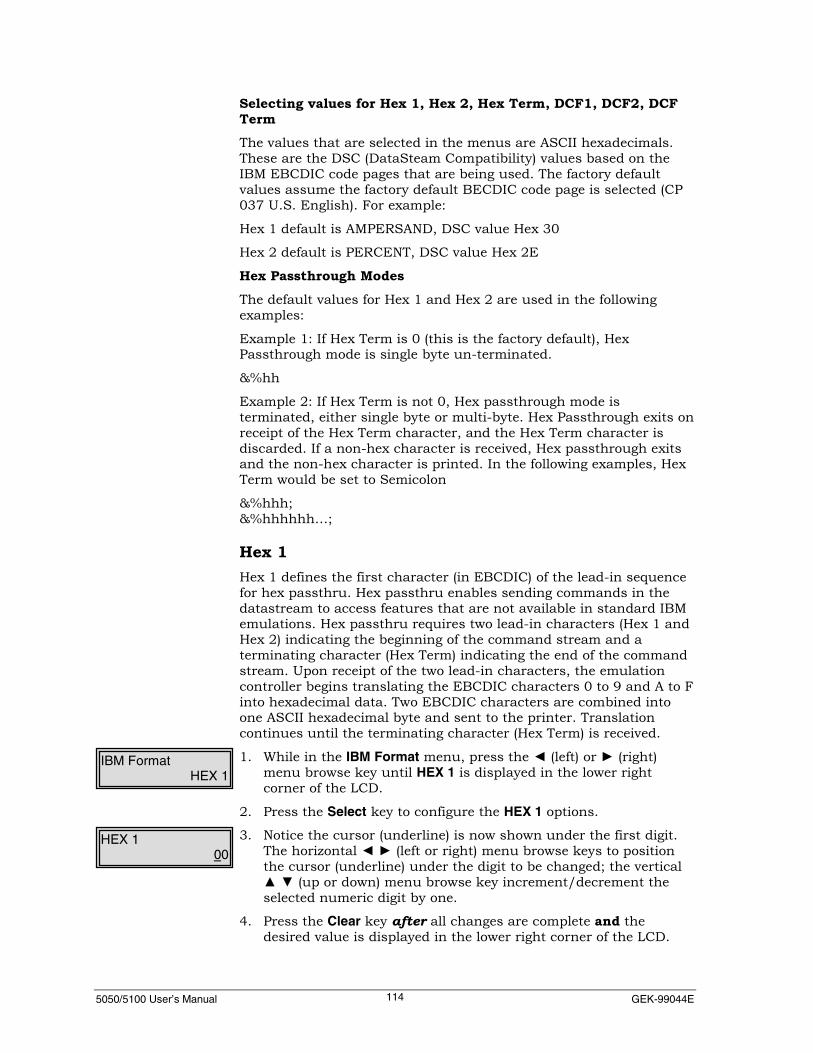
5050/5100 User’s Manual GEK-99044E114
Selecting values for Hex 1, Hex 2, Hex Term, DCF1, DCF2, DCFTermThe values that are selected in the menus are ASCII hexadecimals.These are the DSC (DataSteam Compatibility) values based on theIBM EBCDIC code pages that are being used. The factory defaultvalues assume the factory default BECDIC code page is selected (CP037 U.S. English). For example:
Hex 1 default is AMPERSAND, DSC value Hex 30
Hex 2 default is PERCENT, DSC value Hex 2E
Hex Passthrough ModesThe default values for Hex 1 and Hex 2 are used in the followingexamples:
Example 1: If Hex Term is 0 (this is the factory default), HexPassthrough mode is single byte un-terminated.
&%hh
Example 2: If Hex Term is not 0, Hex passthrough mode isterminated, either single byte or multi-byte. Hex Passthrough exits onreceipt of the Hex Term character, and the Hex Term character isdiscarded. If a non-hex character is received, Hex passthrough exitsand the non-hex character is printed. In the following examples, HexTerm would be set to Semicolon
&%hhh;&%hhhhhh…;
Hex 1Hex 1 defines the first character (in EBCDIC) of the lead-in sequencefor hex passthru. Hex passthru enables sending commands in thedatastream to access features that are not available in standard IBMemulations. Hex passthru requires two lead-in characters (Hex 1 andHex 2) indicating the beginning of the command stream and aterminating character (Hex Term) indicating the end of the commandstream. Upon receipt of the two lead-in characters, the emulationcontroller begins translating the EBCDIC characters 0 to 9 and A to Finto hexadecimal data. Two EBCDIC characters are combined intoone ASCII hexadecimal byte and sent to the printer. Translationcontinues until the terminating character (Hex Term) is received.
1. While in the IBM Format menu, press the ◄ (left) or ► (right)menu browse key until HEX 1 is displayed in the lower rightcorner of the LCD.
2. Press the Select key to configure the HEX 1 options.
3. Notice the cursor (underline) is now shown under the first digit.The horizontal ◄ ► (left or right) menu browse keys to positionthe cursor (underline) under the digit to be changed; the vertical▲ ▼ (up or down) menu browse key increment/decrement theselected numeric digit by one.
4. Press the Clear key after all changes are complete and thedesired value is displayed in the lower right corner of the LCD.
IBM FormatHEX 1
HEX 100
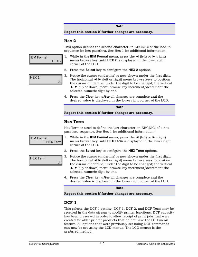
5050/5100 User’s Manual Chapter 5. Using the Setup Menu115
NoteRepeat this section if further changes are necessary.
Hex 2This option defines the second character (in EBCDIC) of the lead-insequence for hex passthru. See Hex 1 for additional information.
1. While in the IBM Format menu, press the ◄ (left) or ► (right)menu browse key until HEX 2 is displayed in the lower rightcorner of the LCD.
2. Press the Select key to configure the HEX 2 options.
3. Notice the cursor (underline) is now shown under the first digit.The horizontal ◄ ► (left or right) menu browse keys to positionthe cursor (underline) under the digit to be changed; the vertical▲ ▼ (up or down) menu browse key increment/decrement theselected numeric digit by one.
4. Press the Clear key after all changes are complete and thedesired value is displayed in the lower right corner of the LCD.
Note
Repeat this section if further changes are necessary.
Hex TermHex Term is used to define the last character (in EBCDIC) of a hexpassthru sequence. See Hex 1 for additional information.
1. While in the IBM Format menu, press the ◄ (left) or ► (right)menu browse key until HEX Term is displayed in the lower rightcorner of the LCD.
2. Press the Select key to configure the HEX Term options.
3. Notice the cursor (underline) is now shown under the first digit.The horizontal ◄ ► (left or right) menu browse keys to positionthe cursor (underline) under the digit to be changed; the vertical▲ ▼ (up or down) menu browse key increment/decrement theselected numeric digit by one.
4. Press the Clear key after all changes are complete and thedesired value is displayed in the lower right corner of the LCD.
Note
Repeat this section if further changes are necessary.
DCF 1This selects the DCF 1 setting. DCF 1, DCF 2, and DCF Term may bereceived in the data stream to modify printer functions. DCF capacityhas been preserved in order to allow receipt of print jobs that werecreated for older printer products that do not have the LCD menufeature. All options that were previously set using DCF commandscan now be set using the LCD menus. The LCD menus is thepreferred method.
IBM FormatHEX 2
HEX 200
IBM FormatHEX Term
HEX Term00

5050/5100 User’s Manual GEK-99044E116
1. While in the IBM Format menu, press the ◄ (left) or ► (right)menu browse key until DCF1 is displayed in the lower right cornerof the LCD.
2. Press the Select key to configure the DCF1 option.
3. Notice the cursor (underline) is now shown under the first digit.Use the horizontal ◄ ► (left or right) menu browse keys toposition the cursor (underline) under the digit to be changes; usethe vertical ▲ ▼ (up or down) menu browse keys toincrement/decrement the selected numeric digit by one.
4. Press the Clear key after all changes are complete and thedesired value is displayed in the lower right corner of the LCD.
NoteRepeat this section if further changes are necessary.
DCF 2This selects the DCF2 setting. See DCF 1 for additional information.
1. While in the IBM Format menu, press the ◄ (left) or ► (right)menu browse key until DCF2 is displayed in the lower right cornerof the LCD.
2. Press the Select key to configure the DCF2 options.
3. Notice the cursor (underline) is now shown under the first digit.Use the horizontal ◄ ► (left or right) menu browse keys toposition the cursor (underline) under the digit to be changes; usethe vertical ▲ ▼ (up or down) menu browse keys toincrement/decrement the selected numeric digit by one.
4. Press the Clear key after all changes are complete and thedesired value is displayed in the lower right corner of the LCD.
Note
Repeat this section if further changes are necessary.
IBM FormatDCF1
DCF100
IBM FormatDCF2
DCF200

5050/5100 User’s Manual Chapter 5. Using the Setup Menu117
DCF TermThis selects the DCF Term setting. See DCF 1 for additionalinformation.
1. While in the IBM Format menu, press the ◄ (left) or ► (right)menu browse key until DCF Term is displayed in the lower rightcorner of the LCD.
2. Press the Select key to configure the DCF Term options.
3. Notice the cursor (underline) is now shown under the first digit.Use the horizontal ◄ ► (left or right) menu browse keys toposition the cursor (underline) under the digit to be changed; usethe vertical ▲ ▼ (up or down) menu browse keys toincrement/decrement the selected numeric digit by one.
4. Press the Clear key after all changes are complete and thedesired value is displayed in the lower right corner of the LCD.
NoteRepeat this section if further changes are necessary.
ASCII DriverThis enables/disables ASCII Driver. When enabled, this menu optionprevents commands in SCS jobs from changing control panelselections of CPI, LPI, MPL, etc. The printer’s SCS controller will notsend any Escape sequences to the print engine.
1. While in the IBM Format menu, press the ◄ (left) or ► (right)menu browse key until ASCII Driver is displayed in the lower rightcorner of the LCD.
2. Press the ▼ (down) menu browse key to access the ASCII Driveroptions.
3. Press the ◄ (left) or ► (right) menu browse key until the desiredoption is displayed. Press the Select key to enable or disable anoption. The < symbol will immediately follow an enabled option.
Print DirectionThis option sets the print direction to either Forward (default), left toright or Reverse, right to left printing. Reverse is for languages thatneed to be right based (i.e. Arabic).
4. While in the IBM Format menu, press the ◄ (left) or ► (right)menu browse key until Print Direction is displayed in the lowerright corner of the LCD.
5. Press the ▼ (down) menu browse key to access the Print Directionoptions.
6. Press the ◄ (left) or ► (right) menu browse key until the desiredoption is displayed. Press the Select key to enable or disable anoption. The < symbol will immediately follow an enabled option.
IBM FormatDCF Term
DCF Term00
IBM FormatASCII Driver
ASCII DriverDisable<
IBM FormatPrint Direction
Print DirectionForward<

5050/5100 User’s Manual GEK-99044E118
Coax CompatThis menu is used to configure the Coax Compat (Coax Compatibility)settings.
1. While in the IBM Format menu, press the ◄ (left) or ► (right)menu browse keys until Coax Compat is displayed in the lowerright corner of the LCD.
2. Press the ▼ (down) menu browse key. Coax Compatibility will bedisplayed in the upper left corner of the LCD.
The following describes the options available.
CaseThis option is valid for DSC/DSE (LU-3) modes only. SCS (LU-1) isalways dual case. It causes the printer to print in upper and lowercase when set to Dual, or in upper case only when set to Mono.
1. While in the Coax Compat menu option, press the ◄ (left) or ►(right) menu browse keys until Case is displayed in the lowerright corner of the LCD.
2. Press the ▼ (down) menu browse key to access the Case options.
3. Press the ◄ (left) or ► (right) menu browse key until the desiredoption is displayed. Press the Select key to enable or disable anoption. The < symbol will immediately follow an enabled option.
LOC Copy FFThis enables/disables the LOC (Local) Copy FF (Form Feed) option. Ifenabled, it causes the printer to execute a form feed after the printbuffer is completed in an operator-initiated local copy print job. Theprinter ejects the page and is set to print at column 1, line 1 of thenext page. This option overrides FF End Buff to allow the printer tomaintain compatibility with application programs designed for earlierprinters.
1. While in the Coax Compat menu, press the ◄ (left) or ► (right)menu browse keys until LOC Copy FF is displayed in the lowerright corner of the display.
2. Press the ▼ (down) menu browse key to access the LOC Copy FFoptions.
3. Press the ◄ (left) or ► (right) menu browse key until the desiredoption is displayed. Press the Select key to enable or disable anoption. The < symbol will immediately follow an enabled option.
IBM FormatCoax Compat
Coax CompatCase
CaseDual<
Coax CompatCase
Coax CompatLOC Copy FF
LOC Copy FFDisable<

5050/5100 User’s Manual Chapter 5. Using the Setup Menu119
FF Before LCThis enables/disables the FF (Form Feed) Before LC (Local Copy)option. If enabled, it causes the printer to execute a form feed beforethe printer buffer is completed in an operator-initiated local copyprint job.
1. While in the Coax Compat menu, press the ◄ (left) or ► (right)menu browse keys until FF Before LC is displayed in the lowerright corner of the display.
2. Press the ▼ (down) menu browse key to access the FF Before LCoptions.
3. Press the ◄ (left) or ► (right) menu browse key until the desiredoption is displayed. Press the Select key to enable or disable anoption. The < symbol will immediately follow an enabled option.
Interv ReqThis enables/disables the Interv Req (Intervention Required) option.When enabled, it causes an intervention required message to be sentto the host computer if the printer is busy or in an error condition.The time before sending the Intervention Required message is set bythe Irq Err TO and Irq Bsy TO options.
1. While in the Coax Compat menu, press the ◄ (left) or ► (right)menu browse keys until Interv Req is displayed in the lower rightcorner of the display.
2. Press the ▼ (down) menu browse key to access the Interv Reqoptions.
3. Press the ◄ (left) or ► (right) menu browse key until the desiredoption is displayed. Press the Select key to enable or disable anoption. The < symbol will immediately follow an enabled option.
Coax CompatFF Before LC
FF Before LCDisable<
Coax CompatInterv Req
Interv ReqEnable<

5050/5100 User’s Manual GEK-99044E120
Irq Err TOIf the Interv Req option is enabled, the IRQ Err TO value representsthe amount of time available to clear an error (such as paper jam orpaper out, etc.) before the printer notifies the host computer of theerror condition. Each increment represents 5 seconds. The defaultvalue of 12 represents 60 seconds.
1. While in the Coax Compat menu, press the ◄ (left) or ► (right)menu browse key until IRQ Err TO is displayed in the lower rightcorner of the LCD.
2. Press the Select key to configure the Irq Err TO option.
3. Notice the cursor (underline) is now shown under the first digit.Use the horizontal ◄ ► (left or right) menu browse keys toposition the cursor (underline) under the digit to be changed; usethe vertical ▲ ▼ (up or down) menu browse keys toincrement/decrement the selected numeric digit by one.
4. Press the Clear key after all changes are complete and the desiredvalue is displayed in the lower right corner of the LCD.
Note
Repeat this section if further changes are necessary.
Irq Bsy TOIf the Interv Req option is enabled and the printer is offline for aperiod of time exceeding the IRQ BSY To value selected, the LCDdisplay will show “ON HOLD TIMOUT” and the host will be sent anIntervention Required message.
1. While in the Coax Compat menu, press the ◄ (left) or ► (right)menu browse key until IRQ Bsy TO is displayed in the lower rightcorner of the LCD.
2. Press the Select key to configure the Irq Bsy TO option.
3. Notice the cursor (underline) is now shown under the first digit.Use the horizontal ◄ ► (left or right) menu browse keys toposition the cursor (underline) under the digit to be changed; usethe vertical ▲ ▼ (up or down) menu browse keys toincrement/decrement the selected numeric digit by one.
4. Press the Clear key after all changes are complete and the desiredvalue is displayed in the lower right corner of the LCD.
NoteRepeat this section if further changes are necessary.
Coax CompatIRQ Err To
IRQ Err To000
Coax CompatIrq Bsy To
Irq Bsy To000
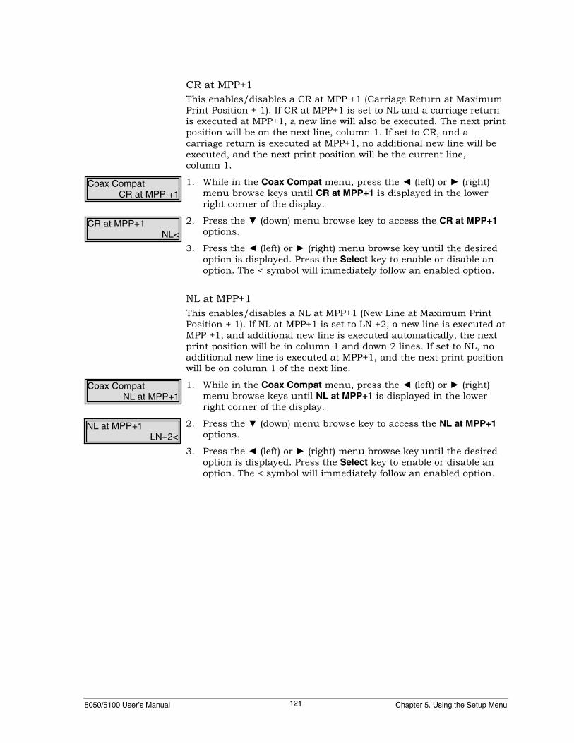
5050/5100 User’s Manual Chapter 5. Using the Setup Menu121
CR at MPP+1This enables/disables a CR at MPP +1 (Carriage Return at MaximumPrint Position + 1). If CR at MPP+1 is set to NL and a carriage returnis executed at MPP+1, a new line will also be executed. The next printposition will be on the next line, column 1. If set to CR, and acarriage return is executed at MPP+1, no additional new line will beexecuted, and the next print position will be the current line,column 1.
1. While in the Coax Compat menu, press the ◄ (left) or ► (right)menu browse keys until CR at MPP+1 is displayed in the lowerright corner of the display.
2. Press the ▼ (down) menu browse key to access the CR at MPP+1options.
3. Press the ◄ (left) or ► (right) menu browse key until the desiredoption is displayed. Press the Select key to enable or disable anoption. The < symbol will immediately follow an enabled option.
NL at MPP+1This enables/disables a NL at MPP+1 (New Line at Maximum PrintPosition + 1). If NL at MPP+1 is set to LN +2, a new line is executed atMPP +1, and additional new line is executed automatically, the nextprint position will be in column 1 and down 2 lines. If set to NL, noadditional new line is executed at MPP+1, and the next print positionwill be on column 1 of the next line.
1. While in the Coax Compat menu, press the ◄ (left) or ► (right)menu browse keys until NL at MPP+1 is displayed in the lowerright corner of the display.
2. Press the ▼ (down) menu browse key to access the NL at MPP+1options.
3. Press the ◄ (left) or ► (right) menu browse key until the desiredoption is displayed. Press the Select key to enable or disable anoption. The < symbol will immediately follow an enabled option.
Coax CompatCR at MPP +1
CR at MPP+1NL<
Coax CompatNL at MPP+1
NL at MPP+1LN+2<

5050/5100 User’s Manual GEK-99044E122
FF DataThis enables/disables FF Data (Form Feed Followed by Data). The FFData option is used to select the action taken if a form feed isreceived by the printer and it is not the last character in the IBMprint buffer. When set to COL 2, the current print position after theform feed will be the second column on line one of the next form. Ifset to COL 1, the current print position will be the first column online one of the next form.
1. While in the Coax Compat menu, press the ◄ (left) or ► (right)menu browse keys until FF Data is displayed in the lower rightcorner of the display.
2. Press the ▼ (down) menu browse key to access the FF Dataoptions.
3. Press the ◄ (left) or ► (right) menu browse key until the desiredoption is displayed. Press the Select key to enable or disable anoption. The < symbol will immediately follow an enabled option.
FF EndBuffThe FF End Buff option is used to select the action taken if a formfeed is received by the printer and it is the last character in the IBMprint buffer. When set to LN 2, the current print position after theform feed will be the first column on line two of the next form. If setto LN 1, the current print position will be the first column on line oneof the next form.
1. While in the Coax Compat menu, press the ◄ (left) or ► (right)menu browse keys until FF EndBuff is displayed in the lower rightcorner of the display.
2. Press the ▼ (down) menu browse key to access the FF EndBuffoptions.
3. Press the ◄ (left) or ► (right) menu browse key until the desiredoption is displayed. Press the Select key to enable or disable anoption. The < symbol will immediately follow an enabled option.
Coax CompatFF Data
FF DataCol 1<
Coax CompatFF EndBuff
FF EndBuffLN 1<
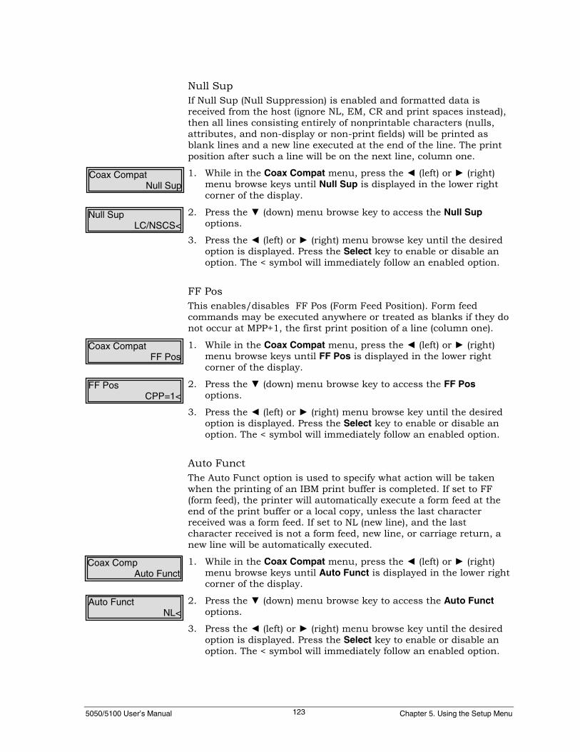
5050/5100 User’s Manual Chapter 5. Using the Setup Menu123
Null SupIf Null Sup (Null Suppression) is enabled and formatted data isreceived from the host (ignore NL, EM, CR and print spaces instead),then all lines consisting entirely of nonprintable characters (nulls,attributes, and non-display or non-print fields) will be printed asblank lines and a new line executed at the end of the line. The printposition after such a line will be on the next line, column one.
1. While in the Coax Compat menu, press the ◄ (left) or ► (right)menu browse keys until Null Sup is displayed in the lower rightcorner of the display.
2. Press the ▼ (down) menu browse key to access the Null Supoptions.
3. Press the ◄ (left) or ► (right) menu browse key until the desiredoption is displayed. Press the Select key to enable or disable anoption. The < symbol will immediately follow an enabled option.
FF PosThis enables/disables FF Pos (Form Feed Position). Form feedcommands may be executed anywhere or treated as blanks if they donot occur at MPP+1, the first print position of a line (column one).
1. While in the Coax Compat menu, press the ◄ (left) or ► (right)menu browse keys until FF Pos is displayed in the lower rightcorner of the display.
2. Press the ▼ (down) menu browse key to access the FF Posoptions.
3. Press the ◄ (left) or ► (right) menu browse key until the desiredoption is displayed. Press the Select key to enable or disable anoption. The < symbol will immediately follow an enabled option.
Auto FunctThe Auto Funct option is used to specify what action will be takenwhen the printing of an IBM print buffer is completed. If set to FF(form feed), the printer will automatically execute a form feed at theend of the print buffer or a local copy, unless the last characterreceived was a form feed. If set to NL (new line), and the lastcharacter received is not a form feed, new line, or carriage return, anew line will be automatically executed.
1. While in the Coax Compat menu, press the ◄ (left) or ► (right)menu browse keys until Auto Funct is displayed in the lower rightcorner of the display.
2. Press the ▼ (down) menu browse key to access the Auto Functoptions.
3. Press the ◄ (left) or ► (right) menu browse key until the desiredoption is displayed. Press the Select key to enable or disable anoption. The < symbol will immediately follow an enabled option.
Coax CompatNull Sup
Null SupLC/NSCS<
Coax CompatFF Pos
FF PosCPP=1<
Coax CompAuto Funct
Auto FunctNL<
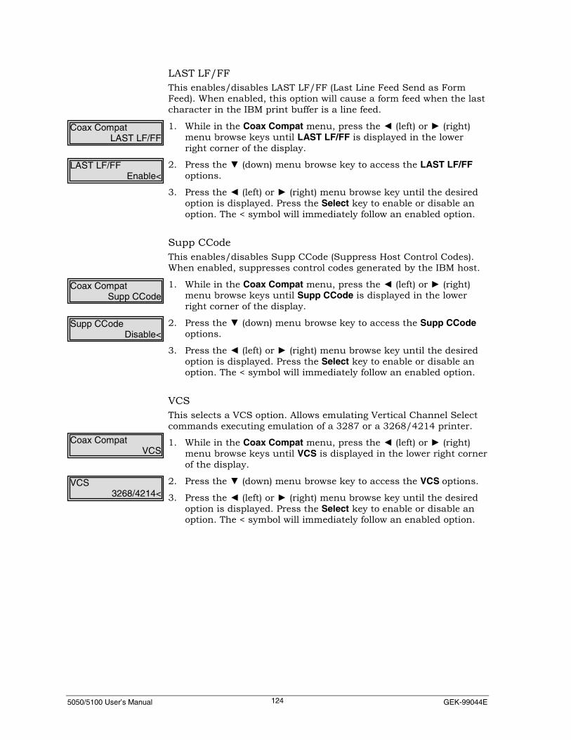
5050/5100 User’s Manual GEK-99044E124
LAST LF/FFThis enables/disables LAST LF/FF (Last Line Feed Send as FormFeed). When enabled, this option will cause a form feed when the lastcharacter in the IBM print buffer is a line feed.
1. While in the Coax Compat menu, press the ◄ (left) or ► (right)menu browse keys until LAST LF/FF is displayed in the lowerright corner of the display.
2. Press the ▼ (down) menu browse key to access the LAST LF/FFoptions.
3. Press the ◄ (left) or ► (right) menu browse key until the desiredoption is displayed. Press the Select key to enable or disable anoption. The < symbol will immediately follow an enabled option.
Supp CCodeThis enables/disables Supp CCode (Suppress Host Control Codes).When enabled, suppresses control codes generated by the IBM host.
1. While in the Coax Compat menu, press the ◄ (left) or ► (right)menu browse keys until Supp CCode is displayed in the lowerright corner of the display.
2. Press the ▼ (down) menu browse key to access the Supp CCodeoptions.
3. Press the ◄ (left) or ► (right) menu browse key until the desiredoption is displayed. Press the Select key to enable or disable anoption. The < symbol will immediately follow an enabled option.
VCSThis selects a VCS option. Allows emulating Vertical Channel Selectcommands executing emulation of a 3287 or a 3268/4214 printer.
1. While in the Coax Compat menu, press the ◄ (left) or ► (right)menu browse keys until VCS is displayed in the lower right cornerof the display.
2. Press the ▼ (down) menu browse key to access the VCS options.
3. Press the ◄ (left) or ► (right) menu browse key until the desiredoption is displayed. Press the Select key to enable or disable anoption. The < symbol will immediately follow an enabled option.
Coax CompatLAST LF/FF
LAST LF/FFEnable<
Coax CompatSupp CCode
Supp CCodeDisable<
Coax CompatVCS
VCS3268/4214<

5050/5100 User’s Manual Chapter 5. Using the Setup Menu125
CommThe Comm option enables/disables the Extended Attribute Buffer(EAB) and enables/disables the Query Reply. When set to EAB, EABis enabled, but not Query Reply. When set to QUERY/EAB, EAB andQuery Reply are both enabled. In the Disabled state, both EAB andQuery Reply are disabled.
1. While in the Coax Compat menu, press the ◄ (left) or ► (right)menu browse keys until Comm is displayed in the lower rightcorner of the display.
2. Press the ▼ (down) menu browse key to access the Commoptions.
3. Press the ◄ (left) or ► (right) menu browse key until the desiredoption is displayed. Press the Select key to enable or disable anoption. The < symbol will immediately follow an enabled option.
Coax CompatComm
CommQUERY/EAB<

5050/5100 User’s Manual GEK-99044E126
SELECT EMULThis menu is used to select a printer emulation. This printer canemulate (become functionally similar to) ANSI (4800), ANSI (4410),FX286e, IBM ProPrinter, P300/600, DEC LG (Digital Branded modelsonly), PSeries, and DEC PPL3.
Which emulation to use will depend on what control codes andescape sequences will be sent by the host. (See Programmer’s Manual,for information on each emulation.)
1. While in Set Up menu, press the ◄ (left) or ► (right) menu browsekeys until Select Emul is displayed in the lower right corner of theLCD.
2. Press the ▼ (down) menu browse key to access the Select Emuloptions.
3. Press the ◄ (left) or ► (right) menu browse keys until theemulation desired is displayed in the lower right corner of theLCD.
4. Press the Select key to select an emulation option. The < symbolwill now immediately follow the saved emulation option.
NoteIf there is an IBM CX/TX (Coax/Twinax) interface board installedin expansion slot 1 or expanstion slot 2, the software in theprinter will be either an SCS load which defaults to the SCS filterenabled or an IPDS load, which defaults to the IPDS filterenabled. The Emulation will be ANSI (4800) and the operator isunable to select another Emulation because SCS and IPDS filtersmust have the ANSI (4800) selected.If the printer is not using the Coax or Twinax interface and anEmulation other than ANSI (4800) is desired (i.e. parallel):Determine which expansion slot contains the installed CX/TXboard.If the printer is an IPDS printer, in the Expansion(n) menu,where (n) is the number of the expansion slot, disable(unselect)the IPDS option. If the printer is an SCS printer, in theExpansion(n) menu, where (n) is the number of the expansionslot, disable(unselect) the SCS option. SeeExpansion1/Expansion2 on page 42 for procedures to performthis step.
Set UpSelect Emul
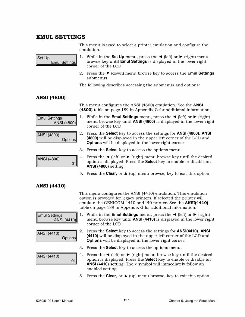
5050/5100 User’s Manual Chapter 5. Using the Setup Menu127
EMUL SETTINGSThis menu is used to select a printer emulation and configure theemulation.
1. While in the Set Up menu, press the ◄ (left) or ► (right) menubrowse key until Emul Settings is displayed in the lower rightcorner of the LCD.
2. Press the ▼ (down) menu browse key to access the Emul Settingssubmenus.
The following describes accessing the submenus and options:
ANSI (4800)This menu configures the ANSI (4800) emulation. See the ANSI(4800) table on page 189 in Appendix G for additional information.
1. While in the Emul Settings menu, press the ◄ (left) or ► (right)menu browse key until ANSI (4800) is displayed in the lower rightcorner of the LCD.
2. Press the Select key to access the settings for ANSI (4800). ANSI(4800) will be displayed in the upper left corner of the LCD andOptions will be displayed in the lower right corner.
3. Press the Select key to access the options menu.
4. Press the ◄ (left) or ► (right) menu browse key until the desiredoption is displayed. Press the Select key to enable or disable anANSI (4800) setting.
5. Press the Clear, or ▲ (up) menu browse, key to exit this option.
ANSI (4410)This menu configures the ANSI (4410) emulation. This emulationoption is provided for legacy printers. If selected the printer willemulate the GENICOM 4410 or 4440 printer. See the ANSI(4410)table on page 189 in Appendix G for additional information.
1. While in the Emul Settings menu, press the ◄ (left) or ► (right)menu browse key until ANSI (4410) is displayed in the lower rightcorner of the LCD.
2. Press the Select key to access the settings for ANSI(4410). ANSI(4410) will be displayed in the upper left corner of the LCD andOptions will be displayed in the lower right corner.
3. Press the Select key to access the options menu.
4. Press the ◄ (left) or ► (right) menu browse key until the desiredoption is displayed. Press the Select key to enable or disable anANSI (4410) setting. The < symbol will immediately follow anenabled setting.
5. Press the Clear, or ▲ (up) menu browse, key to exit this option.
Set UpEmul Settings
Emul SettingsANSI (4800)
ANSI (4800)Options
ANSI (4800)01
Emul SettingsANSI (4410)
ANSI (4410)Options
ANSI (4410)01
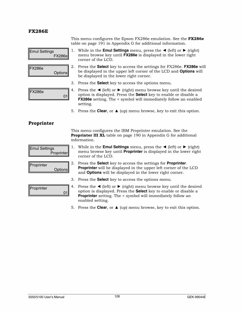
5050/5100 User’s Manual GEK-99044E128
FX286EThis menu configures the Epson FX286e emulation. See the FX286etable on page 191 in Appendix G for additional information.
1. While in the Emul Settings menu, press the ◄ (left) or ► (right)menu browse key until FX286e is displayed in the lower rightcorner of the LCD.
2. Press the Select key to access the settings for FX286e. FX286e willbe displayed in the upper left corner of the LCD and Options willbe displayed in the lower right corner.
3. Press the Select key to access the options menu.
4. Press the ◄ (left) or ► (right) menu browse key until the desiredoption is displayed. Press the Select key to enable or disable aFX286e setting. The < symbol will immediately follow an enabledsetting.
5. Press the Clear, or ▲ (up) menu browse, key to exit this option.
ProprinterThis menu configures the IBM Proprinter emulation. See theProprinter III XL table on page 190 in Appendix G for additionalinformation.
1. While in the Emul Settings menu, press the ◄ (left) or ► (right)menu browse key until Proprinter is displayed in the lower rightcorner of the LCD.
2. Press the Select key to access the settings for Proprinter.Proprinter will be displayed in the upper left corner of the LCDand Options will be displayed in the lower right corner.
3. Press the Select key to access the options menu.
4. Press the ◄ (left) or ► (right) menu browse key until the desiredoption is displayed. Press the Select key to enable or disable aProprinter setting. The < symbol will immediately follow anenabled setting.
5. Press the Clear, or ▲ (up) menu browse, key to exit this option.
Emul SettingsProprinter
Emul SettingsFX286e
ProprinterOptions
FX286eOptions
FX286e01
Proprinter01

5050/5100 User’s Manual Chapter 5. Using the Setup Menu129
P 300/600This menu configures the Printronix P 300/600 emulation. See thePrintronix P300/600 table on page 192 in Appendix G for additionalinformation.
1. While in the Emul Settings menu, press the ◄ (left) or ► (right)menu browse key until P 300/600 is displayed in the lower rightcorner of the LCD.
2. Press the Select key to access the settings for P 300/600. P 300/600will be displayed in the upper left corner of the LCD and Optionswill be displayed in the lower right corner.
3. Press the Select key to access the options menu.
4. Press the ◄ (left) or ► (right) menu browse key until the desiredoption is displayed. Press the Select key to enable or disable a P300/600 setting. The < symbol will immediately follow an enabledsetting.
5. Press the Clear, or ▲ (up) menu browse, key to exit this option.
DEC LGThis menu configures the DEC LG emulation. See the DEC LG Plustable on page 192 in Appendix G for additional information.
1. While in the Emul Settings menu, press the ◄ (left) or ► (right)menu browse key until DEC LG is displayed in the lower rightcorner of the LCD.
2. Press the Select key to access the settings for DEC LG. DEC LGwill be displayed in the upper left corner of the LCD and Optionswill be displayed in the lower right corner.
3. Press the Select key to access the options menu.
4. Press the ◄ (left) or ► (right) menu browse key until the desiredoption is displayed. Press the Select key to enable or disable aDEC LG setting. The < symbol will immediately follow an enabledsetting.
5. Press the Clear, or ▲ (up) menu browse key to exit this option.
Emul SettingsP 300/600
P 300/600Options
P 300/60001
Emul SettingsDEC LG
DEC LGOptions
DEC LG01

5050/5100 User’s Manual GEK-99044E130
PseriesThis menu configures the the Pseries emulation. See the PrintronixPseries table on page 192 in Appendix G for additional information.
NoteUnder the menu option SFCC (Special Function ControlCharacter), the user may define a SFCC character. See theProgrammer’s Manual for additional information.
1. While in the Emul Settings menu, press the ◄ (left) or ► (right)menu browse key until Pseries is displayed in the lower rightcorner of the LCD.
2. Press the Select key to access the settings for Pseries. Pseries willbe displayed in the upper left corner of the LCD and Options willbe displayed in the lower right corner.
3. Press the Select key to access the options menu.
4. Press the ◄ (left) or ► (right) menu browse key until the desiredoption is displayed. Press the Select key to enable or disable aPseries setting. The < symbol will immediately follow an enabledsetting.
5. Press the Clear, or ▲ (up) menu browse key to exit this option.
DEC PPL3This menu configures the DEC PPL3 emulation. See the DEC PPL3table on page 192 in Appendix G for additional information.
1. While in the Emul Settings menu, press the ◄ (left) or ► (right)menu browse key until DEC PPL3 is displayed in the lower rightcorner of the LCD.
2. Press the Select key to access the settings for DEC PPL3. DECPPL3 will be displayed in the upper left corner of the LCD andOptions will be displayed in the lower right corner.
3. Press the Select key to access the options menu.
4. Press the ◄ (left) or ► (right) menu browse key until the desiredoption is displayed. Press the Select key to enable or disable aDEC PPL3 setting. The < symbol will immediately follow anenabled setting.
5. Press the Clear, or ▲ (up) menu browse, key to exit this option.
Emul SettingsDEC PPL3
Emul SettingsPseries
DEC PPL3Options
PseriesOptions
PSeries01
DEC PPL301

5050/5100 User’s Manual Chapter 5. Using the Setup Menu131
ENGINE OPTIONSThis menu is used to control the shuttle motor and print wireactuator tiers.
1. While in the Set Up menu, press the ◄ (left) or ► (right) menubrowse key until Engine Options is displayed in the lower rightcorner of the LCD.
2. Press the ▼ (down) menu browse key to access the EngineOptions sub-menus.
The following describes the sub-menus and options available:
DirectionThis menu is used to control the firing or the print wires inrelationship to the swing of the shuttle. Bi-directional mode allowsprinting during both the left and right shuttle swing (normaloperation.)
Printing only in left or right swing of the shuttle is used for trouble-shooting and alignment purposes. A slight increase in the quality ofprinting may be realized using a single-swing option due to thecharacteristics of the timing.
1. While in the Engine Options menu, press the ◄ (left) or ► (right)menu browse keys until Direction is displayed in the lower rightcorner of the LCD.
2. Press the ▼ (down) menu browse key to access the Directionoptions.
3. Press the ◄ (left) or ► (right) menu browse key until the desiredoption is displayed. Press the Select key to enable or disable anoption. The < symbol will immediately follow an enabled option.
EngineOff DelayThis menu is used to set the power-off delay for the shuttle motor.This delay is the time between the moment when no print data isdetected and the moment when the shuttle motor is shut off. A shortdelay time is preferred. If the host is sending data slower than theprinter can print, a longer delay may prevent the time lost when theshuttle is turned off and back on again.
1. While in the Engine Options menu, press the ◄ (left) or ► (right)menu key until EngineOff Delay is displayed in the lower rightcorner of the LCD.
2. Press the ▼ (down) menu browse key to access the EngineOffDelay options.
3. Press the ◄ (left) or ► (right) menu browse key until the desiredoption is displayed. Press the Select key to enable or disable anoption. The < symbol will immediately follow an enabled option.
Engine OptionsDirection
DirectionBi-directional<
Engine OptionsEngineOff Delay
EngineOff Delay2 Seconds<
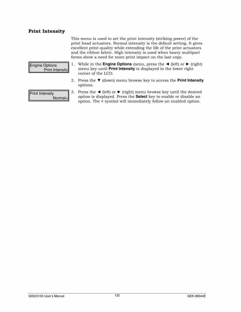
5050/5100 User’s Manual GEK-99044E132
Print IntensityThis menu is used to set the print intensity (striking power) of theprint head actuators. Normal intensity is the default setting. It givesexcellent print quality while extending the life of the print actuatorsand the ribbon fabric. High intensity is used when heavy multipartforms show a need for more print impact on the last copy.
1. While in the Engine Options menu, press the ◄ (left) or ► (right)menu key until Print Intensity is displayed in the lower rightcorner of the LCD.
2. Press the ▼ (down) menu browse key to access the Print Intensityoptions.
3. Press the ◄ (left) or ► (right) menu browse key until the desiredoption is displayed. Press the Select key to enable or disable anoption. The < symbol will immediately follow an enabled option.
Print IntensityNormal<
Engine OptionsPrint Intensity

5050/5100 User’s Manual Chapter 5. Using the Setup Menu133
TEAROFF OPTIONSThis menu is used to modify the tear off feature settings for thisprinter. The TEAROFF function is to position the paper for tear off atthe fanfold perforation; therefore the TEAROFF postion is relative toand dependent on the TOF setting and Form Length setting. Thedefault TEAR OFF settings assume that TOF is set to print the firstline at the physical top of the form (just below the fanfoldperforation).
The TEAROFF postion is factory set to an optimum positiondepending on whether the REAR or TOP paper path is selected. (TOPpaper path is only available on pedestal cabinet models.)
The TEAROFF position can be adjusted up to +/- 2 inches from thedefault value at any time while the TEAROFF function is active usingthe ↑ up or ↓ down arrow keys located on the left side of the controlpanel. The TEAROFF function is active when the display showsTEAROFF, such as after depressing the TEAROFF key.
Adjusting the TEAROFF position does not change the TOF position.However, changing the TOF position does affect the TEAROFFposition. Therefore, the TOF should be set prior to adjusting theTEAROFF. (See Setting Top of Form on page 36 for instructions.)
The TEAROFF position is saved to nonvolatile storage and is reset tofactory defaults only via the action of the Maintenance | Reset toDeflts | Total Init menu operation. (See Reset to Deflts on page 140for instructions.)
1. While in the Set Up menu, press the ◄ (left) or ► (right) menubrowse key until TearOff Options is displayed in the lower rightcorner of the LCD.
2. Press the ▼ (down) menu browse key to access the TearOffOptions submenu options.
The following describes the TearOff Options sub-menus and options:

5050/5100 User’s Manual GEK-99044E134
PathThis menu selects rear exit paper path or top exit paper path. Thismenu is only applicable and visible for the 55 or 60 dBa CabinetModel printers.
1. While in the TearOff Options menu, press ◄ (left) or ► (right)menu browse key until Path is displayed in the lower right cornerof the LCD.
2. Press the ▼ (down) menu browse key to access the Path options.
3. Press the ◄ (left) or ► (right) menu browse key until the desiredoption is displayed. Press the Select key to enable or disable anoption. The < symbol will immediately follow an enabled option.
NoteSee “Selecting the Paper Path” on page 12 in Chapter 2 foradditional procedures when using a top paper path.
RetractThis menu is used to select the length of the paper retraction. NextTOF will retract the paper to the TOF as currently set for the printer.Full Return will retract the paper only the length of a line return thatis currently set for the printer.
1. While in the TearOff Options menu, press ◄ (left) or ► (right)menu browse key until Retract is displayed in the lower rightcorner of the LCD.
2. Press the ▼ (down) menu browse key to access the Retractoptions.
3. Press the ◄ (left) or ► (right) menu browse key until the desiredoption is displayed. Press the Select key to enable or disable anoption. The < symbol will immediately follow an enabled option.
TearOff OptionsPath
PathTop<
TearOff OptionsRetract
RetractNext TOF<
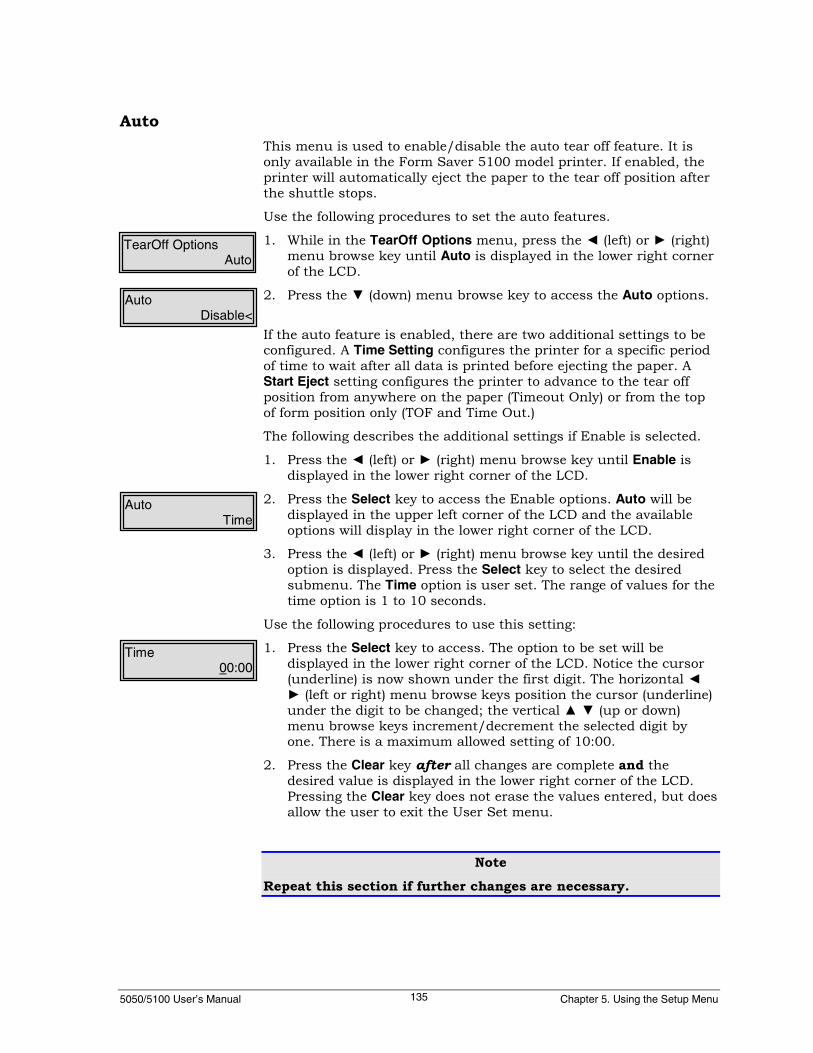
5050/5100 User’s Manual Chapter 5. Using the Setup Menu135
AutoThis menu is used to enable/disable the auto tear off feature. It isonly available in the Form Saver 5100 model printer. If enabled, theprinter will automatically eject the paper to the tear off position afterthe shuttle stops.
Use the following procedures to set the auto features.
1. While in the TearOff Options menu, press the ◄ (left) or ► (right)menu browse key until Auto is displayed in the lower right cornerof the LCD.
2. Press the ▼ (down) menu browse key to access the Auto options.
If the auto feature is enabled, there are two additional settings to beconfigured. A Time Setting configures the printer for a specific periodof time to wait after all data is printed before ejecting the paper. AStart Eject setting configures the printer to advance to the tear offposition from anywhere on the paper (Timeout Only) or from the topof form position only (TOF and Time Out.)
The following describes the additional settings if Enable is selected.
1. Press the ◄ (left) or ► (right) menu browse key until Enable isdisplayed in the lower right corner of the LCD.
2. Press the Select key to access the Enable options. Auto will bedisplayed in the upper left corner of the LCD and the availableoptions will display in the lower right corner of the LCD.
3. Press the ◄ (left) or ► (right) menu browse key until the desiredoption is displayed. Press the Select key to select the desiredsubmenu. The Time option is user set. The range of values for thetime option is 1 to 10 seconds.
Use the following procedures to use this setting:
1. Press the Select key to access. The option to be set will bedisplayed in the lower right corner of the LCD. Notice the cursor(underline) is now shown under the first digit. The horizontal ◄► (left or right) menu browse keys position the cursor (underline)under the digit to be changed; the vertical ▲ ▼ (up or down)menu browse keys increment/decrement the selected digit byone. There is a maximum allowed setting of 10:00.
2. Press the Clear key after all changes are complete and thedesired value is displayed in the lower right corner of the LCD.Pressing the Clear key does not erase the values entered, but doesallow the user to exit the User Set menu.
Note
Repeat this section if further changes are necessary.
Time00:00
TearOff OptionsAuto
AutoDisable<
AutoTime

5050/5100 User’s Manual GEK-99044E136
HORIZ TABThis menu is used to set or clear horizontal tabs. The Horiz Tab maybe set By Column, By Inches, or Clear All Tabs.
NoteThe first two digits represent the tab ID and the last three digitsare the tab location. The number of tab IDs available isdependent on the emulation selected. See “Horizontal/VerticalTab Id Maximum Slots” table in Appendix H.
1. While in Set Up menu, press ◄ (left) or ► (right) menu browse keyuntil Horiz Tab is displayed in the lower right corner of the LCD.
2. Press the ▼ (down) key to access the horizontal tab submenus.Horiz Tab is displayed in the upper left corner of the LCD.
3. Press the ◄ (left) or ► (right) menu browse keys and select ClearAll Tabs, By Columns, or By Inches. Press the Select key to selectone of these options. Hor Tabs Cols, or Hor Tabs IN will bedisplayed in the upper left corner of LCD.
4. The first 16 columns and inches settings are preset settings andare selected using the Select key. The remaining settings areuser-set. (Press the Select key again to modify the horizontal tabsetting ). Notice the cursor (underline) is now shown under thefirst digit and the default number is 000. The four menu browsekeys revert to data entry operation. The horizontal ◄ ► (left orright) keys position the cursor (underline) under the digit to bechanged; the vertical ▲ ▼ (up or down) menu browse keysincrement/decrement the selected digit by one. Each time a user-set tab is entered, it is associated with the tab ID that places itchronologically in sequence. For example, by default the firstHorizontal tab 01: is set to 008. If the user enters a new tabposition of 001, it will be associated with tab ID 01: and 008 willbe moved to tab ID 02 and so on until the maximum horizontaltab IDs are used.
5. Press the Clear key after all changes are complete and thedesired value is displayed in the lower right corner of the LCD.Pressing the Clear key does not erase the values entered, but doesallow the user to exit the User Set menu.
Note
Repeat this section if further changes are necessary.
Set UpHoriz Tab
Horiz TabBy Column
Hor Tabs Cols01:008
Hor Tabs Cols17:New
Hor Tabs Cols17:000<
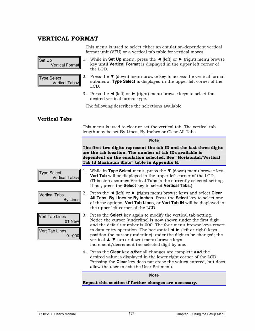
5050/5100 User’s Manual Chapter 5. Using the Setup Menu137
VERTICAL FORMATThis menu is used to select either an emulation-dependent verticalformat unit (VFU) or a vertical tab table for vertical moves.
1. While in Set Up menu, press the ◄ (left) or ► (right) menu browsekey until Vertical Format is displayed in the upper left corner ofthe LCD.
2. Press the ▼ (down) menu browse key to access the vertical formatsubmenu. Type Select is displayed in the upper left corner of theLCD.
3. Press the ◄ (left) or ► (right) menu browse keys to select thedesired vertical format type.
The following describes the selections available.
Vertical TabsThis menu is used to clear or set the vertical tab. The vertical tablength may be set By Lines, By Inches or Clear All Tabs.
NoteThe first two digits represent the tab ID and the last three digitsare the tab location. The number of tab IDs available isdependent on the emulation selected. See “Horizontal/VerticalTab Id Maximum Slots” table in Appendix H.
1. While in Type Select menu, press the ▼ (down) menu browse key.Vert Tab will be displayed in the upper left corner of the LCD.(This step assumes Vertical Tabs is the currently selected setting.If not, press the Select key to select Vertical Tabs.)
2. Press the ◄ (left) or ► (right) menu browse keys and select ClearAll Tabs, By Lines,or By Inches. Press the Select key to select oneof these options. Vert Tab Lines, or Vert Tab IN will be displayed inthe upper left corner of the LCD.
3. Press the Select key again to modify the vertical tab setting.Notice the cursor (underline) is now shown under the first digitand the default number is 000. The four menu browse keys revertto data entry operation. The horizontal ◄ ► (left or right) keysposition the cursor (underline) under the digit to be changed; thevertical ▲ ▼ (up or down) menu browse keysincrement/decrement the selected digit by one.
4. Press the Clear key after all changes are complete and thedesired value is displayed in the lower right corner of the LCD.Pressing the Clear key does not erase the values entered, but doesallow the user to exit the User Set menu.
Note
Repeat this section if further changes are necessary.
Type SelectVertical Tabs<
Set UpVertical Format
Vert Tab Lines01:New
Type SelectVertical Tabs<
Vertical TabsBy Lines
Vert Tab Lines01:000
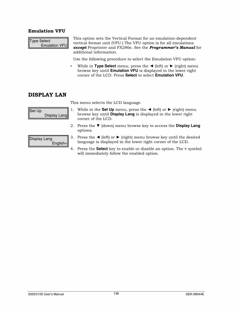
5050/5100 User’s Manual GEK-99044E138
Emulation VFUThis option sets the Vertical Format for an emulation-dependentvertical format unit (VFU.) The VFU option is for all emulationsexcept Proprinter and FX286e. See the Programmer’s Manual foradditional information.
Use the following procedure to select the Emulation VFU option:
▪ While in Type Select menu, press the ◄ (left) or ► (right) menubrowse key until Emulation VFU is displayed in the lower rightcorner of the LCD. Press Select to select Emulation VFU.
DISPLAY LANThis menu selects the LCD language.
1. While in the Set Up menu, press the ◄ (left) or ► (right) menubrowse key until Display Lang is displayed in the lower rightcorner of the LCD.
2. Press the ▼ (down) menu browse key to access the Display Langoptions.
3. Press the ◄ (left) or ► (right) menu browse key until the desiredlanguage is displayed in the lower right corner of the LCD.
4. Press the Select key to enable or disable an option. The < symbolwill immediately follow the enabled option.
Type SelectEmulation VFU
Set UpDisplay Lang
Display LangEnglish<

5050/5100 User’s Manual Chapter 6. Using the Maintenance Manual139
CHAPTER 6. USING THE MAINTENANCE MENUThe activities performed under this menu include resetting theprinter to defaults, alignment, head service, power on time and printtime settings, upgrade software functions, and ribbon monitorfunctions.
While in the Offline State, press the ▼ (down) menu browse key toenter the Main Menu. Press the ◄ (left) or ► (right) menu browse keyuntil Maintenance menu is displayed in the bottom right corner of theLCD. Main Menu will be displayed in the upper left corner of the LCD.
To move up or down a level of menu options, press the ▲ (up) or ▼(down) menu browse keys. To move laterally among options on thesame level, use the ◄ (left) or ► (right) menu browse keys.
Currently selected menu options are displayed in the LCD with a <symbol, which follows immediately to the right of the menu option.Some menu options are toggle options and reflect an enabled ordisabled condition. Press the Select key to cause the printer toperform this operation.
Press the Clear key to return to the upper level menu or to Offlinestate when in a first-level menu.
Main MenuMaintenance

5050/5100 User’s Manual GEK-99044E140
RESET TO DEFLTSReset the printer to factory defaults or re-initialize certain groups ofprinter settings.
NoteBefore proceeding with resetting the printer, have a printout ofthe printer’s current settings. This will provide a record ofsettings which may need to be restored after initializing. See the“Show” option on page 42 (Chapter 4 Using the Operator Menu)for additional information.
1. While in the Maintenance menu, press the ◄ (left) or ► (right)menu browse key until Reset to Deflts is displayed in the lowerline of the LCD.
2. Press the ▼ (down) menu browse key to access the reset todefaults options.
3. Press the ◄ (left) or ► (right) menu browse key to select eitherUSA or International.
4. Press the ▼ (down) menu browse key to access either USA orInternational reset options.
5. Press the ◄ (left) or ► (right) menu browse key to select the typeof Reset to Deflts option desired.
NoteThe All Interfaces option will reset all interface settings to thefactory default settings. The All Formats option will reset allpreviously saved formats to factory defaults. The All Emulationsoption will reset all emulation settings to factory defaultsettings. The Total Init option will reset all interfaces, all formats,and all emulations to factory default settings.
6. Press the Select key to reset the printer to factory defaults. Theprinter momentarily displays STARTUP in the LCD and willcomplete a power-up sequence. After completion of a power-upsequence, printer returns to an Online status.
7. If the printer was operating before initialization, it may need to bereconfigured for the specific task at hand. After achieving properconfiguration, print a set of status reports and save for futurereference.
MaintenanceReset to Deflts
Reset to DefltsUSA

5050/5100 User’s Manual Chapter 6. Using the Maintenance Manual141
ALIGNMENTThis menu and its sub-menus are used to make printingadjustments.
Use the following procedures to select this option:
1. While in the Maintenance menu, press the ◄ (left) or ► (right)menu browse key until Alignment is displayed in the lower rightcorner of the LCD.
2. Press the Select or ▼ (down) menu browse key to access theAlignment options.
The following describes the options available:
PatternsPrint the patterns used for adjustments. There are six availablepatterns. Signature will print a small sample of each of the other fivepatterns. The Amplitude Pattern is used to adjust the amplitude. TheHorizontal Timing, Vertical Timing, and Checkerboard Patterns areverification patterns. The Inter-module Gap Pattern is used to verifycorrect print head mounting.
1. While in the Alignment menu, press the ◄ (left) or ► (right) menubrowse key until Patterns is displayed in the lower right corner ofthe LCD.
2. Press the Select or ▼ (down) menu browse key to access thePatterns options.
3. Press the ◄ (left) or ► (right) menu browse key until the desiredpattern option is displayed.
4. Press the Select key to select a pattern to print. CLR to Stop willbe displayed in the lower right corner of the LCD.
5. Press the Clear key to stop printing the pattern. Press the On Linekey to return the printer to the Local menu status or press theClear key to move backwards up a level.
MaintenanceAlignment
AlignmentPatterns
PatternsSignature
SignatureCLEAR to Stop
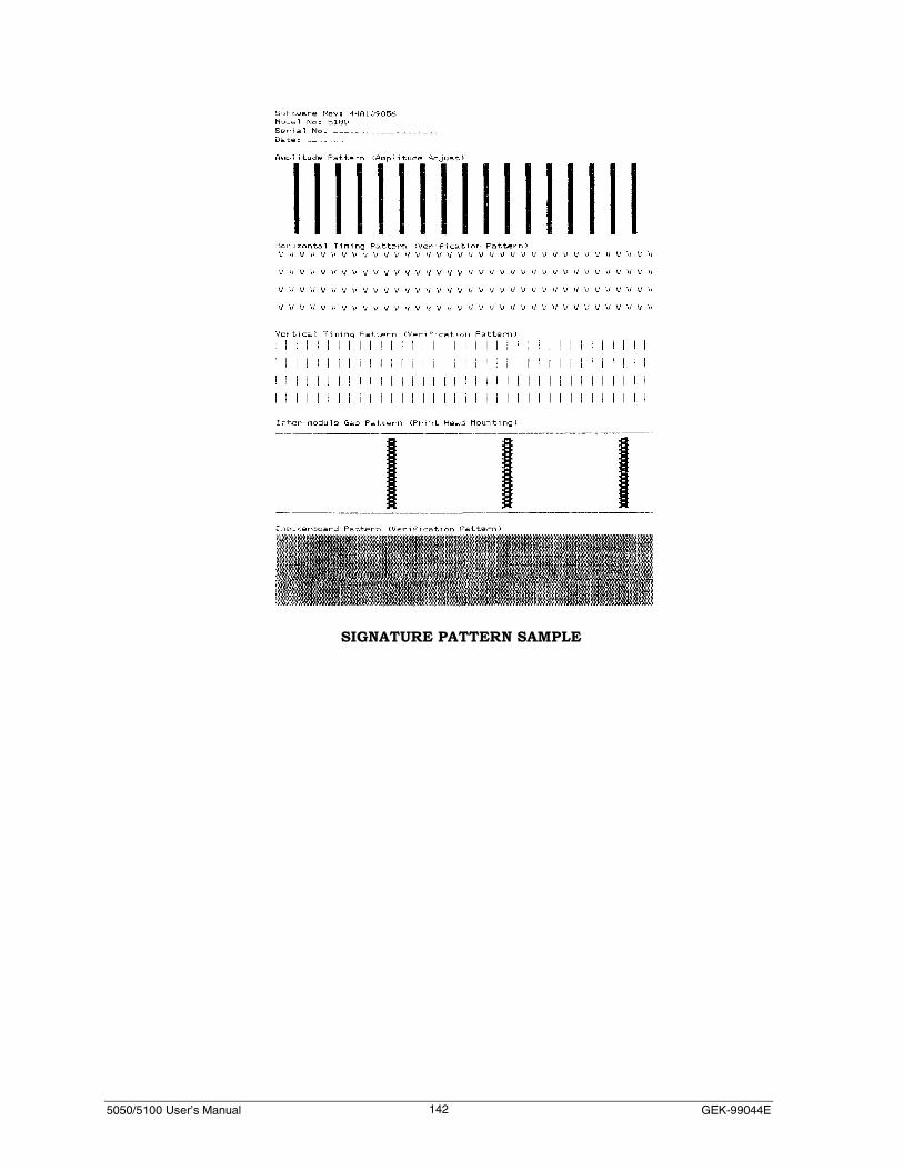
5050/5100 User’s Manual GEK-99044E142
SIGNATURE PATTERN SAMPLE

5050/5100 User’s Manual Chapter 6. Using the Maintenance Manual143
AdjustAmplitudeAdjust the amplitude of the printer. The correct amplitude patternconsists of columns of six dots. The goal of the amplitude adjustmentis to bring the six lines being printed into perfectly spaced verticallines. The amplitude pattern should not have any gaps oroverlapping.
1. While in the Alignment menu, press the ◄ (left) or ► (right) menubrowse key until AdjustAmplitude is displayed in the lower rightcorner of the window.
2. Press the Select key, or the ▼ (down) menu browse key, to accessthe AdjustAmplitude options.
3. Press the ◄ (left) or ► (right) menu browse key until the Patternis displayed in the lower right corner of the LCD.
4. Press the Select key to print the pattern to adjust the amplitude.
5. Use the ◄ (left) or ► (right) menu browse keys to adjust theamplitude while the pattern is printing.
6. Press the Clear key to stop printing the pattern.
7. Press the ◄ (left) or ► (right) key until Save Amplitude isdisplayed in the lower right corner of the LCD.
8. Press the Select key to save the amplitude adjustment.
AlignmentAdjustAmplitude
AdjustAmplitudePattern
AdjustAmplitudeSave Amplitude
SAMPLE PATTERN
PERFECTALIGNMENT
ALIGNMENT TOOWIDE (GAP)
ALIGNMENT TOOCLOSE (OVERLAP)
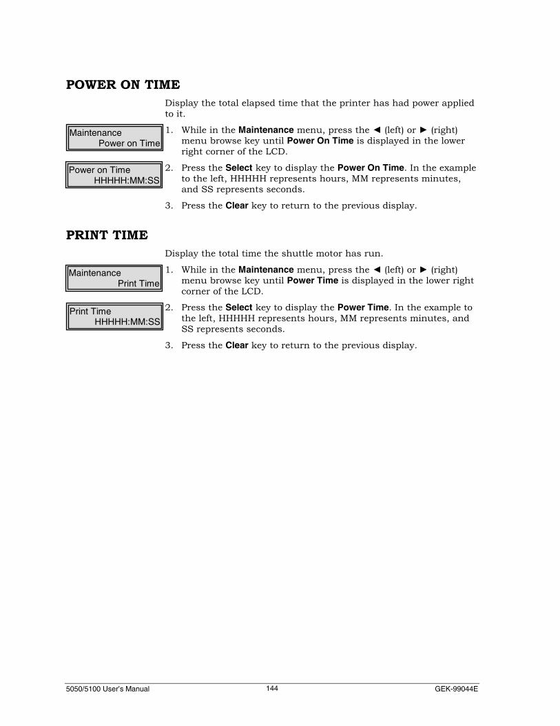
5050/5100 User’s Manual GEK-99044E144
POWER ON TIMEDisplay the total elapsed time that the printer has had power appliedto it.
1. While in the Maintenance menu, press the ◄ (left) or ► (right)menu browse key until Power On Time is displayed in the lowerright corner of the LCD.
2. Press the Select key to display the Power On Time. In the exampleto the left, HHHHH represents hours, MM represents minutes,and SS represents seconds.
3. Press the Clear key to return to the previous display.
PRINT TIMEDisplay the total time the shuttle motor has run.
1. While in the Maintenance menu, press the ◄ (left) or ► (right)menu browse key until Power Time is displayed in the lower rightcorner of the LCD.
2. Press the Select key to display the Power Time. In the example tothe left, HHHHH represents hours, MM represents minutes, andSS represents seconds.
3. Press the Clear key to return to the previous display.
MaintenancePower on Time
Power on TimeHHHHH:MM:SS
MaintenancePrint Time
Print TimeHHHHH:MM:SS

5050/5100 User’s Manual Chapter 6. Using the Maintenance Manual145
RIBBONMONITORWhen this option is enabled, monitoring the ribbon life and resettingthe ribbon counter using the Operator menu. See New Ribbon onpage 42 (Chapter 4. Using the Operator Menu) for additionalinformation.
1. While in the Maintenance menu, press the ◄ (left) or ► (right)menu browse key until RibbonMonitor is displayed in the lowerright corner of the LCD.
2. Press the Select key or the ▼ (down) menu browse key to accessthe RibbonMonitor options.
3. Press the ◄ (left) or ► (right) menu browse key until the desiredoption is displayed in the lower right corner of the LCD.
4. Press the Select key to enable an option. The < symbol willimmediately follow an enabled option. EOL Limit and EOL Warningare user set options.
5. Press the Select key while EOL Limit or EOL Warning is displayedin the lower right corner of the LCD. Notice the cursor (underline)is now shown under the first digit. The horizontal ◄ ► (left orright) menu browse keys to position the cursor (underline) underthe digit to be changed; the vertical ▲ ▼ (up or down) menubrowse key increment/decrement the selected digit by one.
6. Press the Clear key after all changes are complete and thedesired value is displayed in the lower right corner of the LCD.When the printer is online, the LCD window will display the EOLvalue remaining for monitoring purposes.
NoteRepeat this section if further changes are necessary. The validrange of values for EOL Limit is between 30 and 120. The validrange of values for EOL Warning is between 0 and 29.The EOL Limit allows setting the End of Life Limit value for theRibbon. Although setting a limit other than the EOLrecommended for a ribbon is allowed, the current EOL typesavailable are 50M and 75 M.The EOL Warning allows setting the End Of Life Warning valuefor the ribbon. This warning does not cause a fault. It is amonitoring function only.
MaintenanceRibbon Monitor
RibbonMonitorDisable<
EOL Limit000M

5050/5100 User’s Manual GEK-99044E146
HEADSERVICECheck the amount of usage for the individual print heads and toreset the print head counters. The printer keeps track of how manytimes each print head is fired during printing and displays thisinformation on a graph.
1. While in the Maintenance menu, press the ◄ (left) or ► (right)menu browse key until HeadService is displayed in the lower rightcorner of the LCD.
2. Press the Select or ▼ (down) menu browse key to access theHeadService options.
The following describes the options available:
Dot CountsThe dot counters for the print heads can be reset to zero. Thisprocedure is normally used after the installation of a new print head.Resetting this counter arbitrarily is not recommended because thiscounter is used to track print head life.
NoteMake sure the correct print head number is displayed beforeclearing the counter. Once a counter is reset to zero, it cannotbe set back to its original count.
1. While in the HeadService menu, press the ◄ (left) or ► (right)menu browse key until Dot Counts is displayed in the lower rightcorner of the LCD.
2. Press the Select key to access the Dot Counts option. Theindividual print head number will be displayed followed by thenumber of times the individual print head has been fired. In theexample to the left, XX represents the print head number andnnnnnnnnn represents a number. Use the ◄ (left) or ► (right)menu browse key to locate the desired print head counter.
3. Press the Select key to reset the count.
NoteRepeat this section as often as necessary to reset a print headcounter.
MaintenanceHeadService
HeadServiceDot Counts
Select to ResetXX:nnnnnnnnn

5050/5100 User’s Manual Chapter 6. Using the Maintenance Manual147
Print Chart
Print a graph of the number of times individual print heads havebeen fired.
1. While in the HeadService menu, press the � (left) or � (right)menu browse key until Print Chart is displayed in the lower rightcorner of the LCD.
2. Press the Select key to print the print chart. CLR to Stop will bedisplayed in the lower right corner of the LCD.
Actuator Status
Identify an actuator failure.
1. While in the HeadService menu, press the � (left) or � (right)menu browse key until Actuator Status is displayed in the lowerright corner of the LCD.
2. Press the Select key to display the failed actuator. If no actuatorhas failed, the word None will be displayed in the lower left cornerof the LCD. If there is a failed actuator, the number of the failedactuator will be displayed in the lower left corner of the LCD.
HeadServicePrint Chart
Print ChartCLEAR to Stop
HeadServiceActuator Status
Actuators FailedNone
PRINT CHART SAMPLE

5050/5100 User’s Manual GEK-99044E148
UPGRADE FLASHThis menu is used to place the printer in a mode where it receivesdata which is a software upgrade. There are two options available,Onboard Flash and SIMM Flash. The Onboard Flash option is used toupgrade the onboard printer code, which resides on the printersLPCU (Line Printer Control Unit) board. Selecting the SIMM Flashoption will upgrade the printer code residing on the external SIMMFlash. See Appendix F on page 181 for complete upgrade installationinstructions.
NoteMake sure the printer is connected to the host beforeproceeding.
1. While in the Maintenance menu, press the ◄ (left) or ► (right)menu browse key until Upgrade Flash is displayed in the lowerright corner of the LCD.
2. Press the ◄ (left) or ► (right) menu browse key until the desiredupgrade option is displayed in the lower right corner of the LCD.
3. Press the Select key to upgrade the printer. Ready will bedisplayed in the lower left corner of the LCD. (See Appendix F forthe Software Upgrade procedures and additional information.) Toexit this function without upgrading the software, cycle the powerto the printer.
MaintenanceUpgrade Flash
Upgrade Status:Ready
Upgrade FlashOnboard Flash
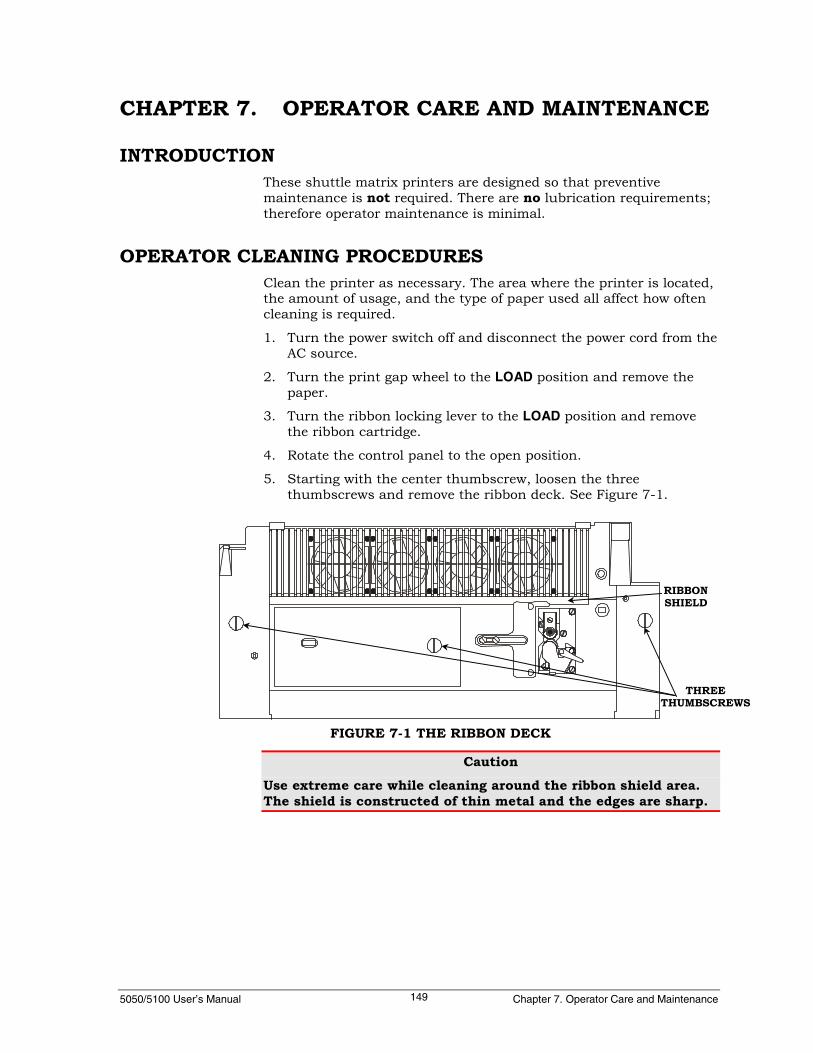
5050/5100 User’s Manual Chapter 7. Operator Care and Maintenance149
CHAPTER 7. OPERATOR CARE AND MAINTENANCE
INTRODUCTIONThese shuttle matrix printers are designed so that preventivemaintenance is not required. There are no lubrication requirements;therefore operator maintenance is minimal.
OPERATOR CLEANING PROCEDURESClean the printer as necessary. The area where the printer is located,the amount of usage, and the type of paper used all affect how oftencleaning is required.
1. Turn the power switch off and disconnect the power cord from theAC source.
2. Turn the print gap wheel to the LOAD position and remove thepaper.
3. Turn the ribbon locking lever to the LOAD position and removethe ribbon cartridge.
4. Rotate the control panel to the open position.
5. Starting with the center thumbscrew, loosen the threethumbscrews and remove the ribbon deck. See Figure 7-1.
CautionUse extreme care while cleaning around the ribbon shield area.The shield is constructed of thin metal and the edges are sharp.
FIGURE 7-1 THE RIBBON DECK
THREETHUMBSCREWS
RIBBONSHIELD
5050/5100 User’s Manual GEK-99044E150
6. Vacuum the print head area using a soft bristle brush to dislodgepaper debris. Wipe away any accumulation of dust from theribbon shield and striker bar area.
7. Blow dust out of, or away from, the paper jam sensor on theupper left tractor.
8. Blow dust out off or away from, the paper out sensor on the lowerleft tractor.
9. Blow dust out of, or away from, the ribbon weld sensor located onthe left of the print heads.
10. Vacuum any paper debris that has accumulated inside the paperstorage area.
11. Vacuum both the top and bottom side of the ribbon deck. Makesure the ribbon motion sensor is clean.
12. Reinstall the ribbon deck making sure all three thumbscrews aretightened.
13. Inspect the ribbon fabric for wear before reinstalling the ribboncartridge.
14. Clean the outside surfaces of the printer with a clean damp cloth.Dampen the cloth with water. Do not use cleaning solutions.Always dry the outside cabinet surfaces with a clean dry cloth.
15. Reconnect the power cord and apply power to the printer foroperation.
OPERATOR TROUBLESHOOTINGMany of the operating faults that can occur are operator-correctable.They are often related to an incorrect setup, wrong adjustment, or theneed to replenish consumables.
Initializing the Printer – Newly installed parts or options, powerfluctuations, static buildup, or errant electrical signals may cause theprinter electronics to lock up. Initializing the printer will clear thisproblem as long as no damage has been done. (See “Chapter 3 -Initializing the Printer”).
Use the initialization procedure when:
▪ Inputs to the control panel are ignored or misinterpreted.
▪ The printer performs unexplained actions or ignores commands.
▪ The printer misinterprets valid commands from the host.

5050/5100 User’s Manual Chapter 7. Operator Care and Maintenance151
The remainder of this chapter is divided into the following sectionsand contains information as a help guide through possible problems.
TABLE 7-1 – Soft Fault Displays, lists display messages that mayappear that do not stop the printer.
TABLE 7-2 – Miscellaneous Non-Fault Messages
TABLE 7-3 –Hard Fault Displays, lists display messages that mayappear when printing has stopped unexpectedly. It also lists theprobable cause and/or the action needed to clear the fault.TABLE 7-4 – Electrical Problems addresses display, keys, or incorrectdata printout problems.
TABLE 7-5 – Mechanical Problems addresses problems with paperfeeding, print quality, and incorrect adjustments.
TABLE 7-6 – Diagnostic Fault Codes explains faults that may bedetected during self-test diagnostics.
TABLE 7-7 – Serial Interface Errors
Print Head Actuator Replacement – Step-by-step replacementinstructions and information that may allow using the printer if areplacement print head is not immediately available.

5050/5100 User’s Manual GEK-99044E152
Soft FaultsWhen a soft fault occurs, printing stops and operator intervention isrequired.
Some change in the data being sent to the printer may be required(See Programmer’s Manual).
If a wire driver or print head actuator fails (see the first two displaysin Table 7-1), printing may continue without damage to the printer(see the section on print head replacement).
Either Online or Offline will be displayed in upper left corner of thedisplay window. The following fault messages will be displayed in thelower right corner of the display window:

5050/5100 User’s Manual Chapter 7. Operator Care and Maintenance153
TABLE 7-1Soft Fault Displays
DISPLAY MEANING CORRECTIVE ACTIONChange Ribbon The Ribbon monitor feature has
detected that the specifiednumber of dots has been printedwith the current ribbon.
Press the Clear key to ignorethis warning and continueprinting, or replace the currentribbon. Reset the ribbon countin the operator menu (if RibbonMonitor is enabled).
Service Time Service time was set to zero or thetimer has failed.
Press the Clear key to clear thefault.
Paper Almost Out Low paper print mode. Press the Clear key to enter LowPaper printing mode or replacethe paper supply.
VFU Missing TOF Missing TOF in the VFU loadsequence.
Press the Clear key to clear thefault. Verify data being sent tothe printer by the host system.
VFU PI Lead Paper Instruction lead: The menuoption for PI lead selection is setincorrectly.
Press the Clear key to clear thefault. Change the PI Lead settingusing the Set Up menu.
Invalid VFU Seq There is an invalid character(s) inthe VFU load sequence.
Press the Clear key to clear thefault. Verify data being sent tothe printer by the host system.
VFU Tbl Too Long The VFU table length has beenexceeded.
Press the Clear key to clear thefault. Verify data being sent tothe printer by the host system.
Paper Out Paper supply is depleted. Load paper and set top of form.The paper out sensor is resetwhen paper is inserted in thelower tractors and the Clear keyis pressed.
Paper Jam No paper movement has beensensed by the paper motionsensor.
Check for paper jam and clearthe jam using the followingprocedure:1. Turn the print gap wheel to
the LOAD position andphysically clear the paperjam.
2. Reload paper and readjustright side tractors, papertension, and gap.
3. Press the Clear key to clearthe fault.
Clean the paper motion sensorlocated on the upper left tractor.

5050/5100 User’s Manual GEK-99044E154
TABLE 7-1Soft Fault Displays (Continued)
No Ribbon Ribbon cartridge is missing,installed incorrectly, or damaged.
See “Ribbon Removal andInstallation” on page 22 inChapter 2.
Ribbon Jam Ribbon has stopped moving. 1. Remove the ribbon cartridge.2. Clean the ribbon motion
sensor.3. Inspect (replace if neccessary)
and reinstall the ribboncartridge.
Press the Clear key to clear thefault.
Ribbon Weld A specified amount of time haspassed without detecting theribbon weld. The ribbon may bejammed or broken.
Check the ribbon. If necessary,replace ribbon. See “RibbonRemoval and Installation” onpage 22 in Chapter 2.
Ribbon Weld Pass The ribbon weld is passing by theactuators while the printer issuspended.
Press the Clear key to clear thefault.
Striker Bar Open Print gap wheel is turned to theOPEN position.
Adjust Gap Wheel to properpaper gap.

5050/5100 User’s Manual Chapter 7. Operator Care and Maintenance155
Miscellaneous Non-Fault MessagesEither Online or Offline will be displayed in upper left corner of thedisplay window. The following fault messages are displayed in thelower right corner of the display window:
Table 7-2Miscellaneous Non-Fault Messages
DISPLAY MEANINGReady Ready is the normal display when no faults exist.StandbyMode
Printer deselected by host (DC3 received from theSerial Interface).
Tearoff Paper is in position for tear off at rear paper exit.
TopTearoffPaper is in position for tear off at top paper exit.See “Tearoff” in Chaper 3 for additionalinformation.

5050/5100 User’s Manual GEK-99044E156
Hard FaultsWhen a hard fault occurs, the printer will be inoperative. Operatorintervention may correct the fault, however service may be required.Correct the condition causing the fault, if possible, and press theCLEAR key to clear the fault display.

5050/5100 User’s Manual Chapter 7. Operator Care and Maintenance157
TABLE 7-3Hard Fault Displays
DISPLAY MEANINGDriver Circuit All actuators on an entire tier fail. Call for service.Shuttle Overload Shuttle drive motor is stalled or
overloaded.Check for interferencecaused by a paper jam orprint gap adjusted tootight. If problem persists,call for service.
Low Power Power supply has sensed low linevoltage or is temporarily overloadedby continuous high density printing.
Check for irregularvoltage from powersource. If problempersists, call for service.
Image Logic Fail No image logic dot request processedfor 5 seconds.
Try to clear fault bycycling power andinitializing the printer. Ifproblem persists, call forservice.
NVRAM Reinit NVRAM has been initialized. Press Clear key tocontinue. If problemcontinues, call for service.
No Font No printable font found in printer. Try to clear fault bycycling power andinitializing. If fault doesnot clear, call for service.
Bad Wire Driver A defective wire driver has been found(see Note 1).
Move or replace actuatormodules. If problempersists, call for service.
Bad Actuator A print head actuator problem hasbeen found (see Note 1).
Move or replace actuatormodules. If problempersists, call for service.
LEFT FAN The left print head fan in the ribbondeck has failed. Call for service.
LEFT CENTERFAN
The left center print head fan in theribbon deck has failed. Call for service.
RIGHT CENTERFAN
The right center print head fan in theribbon deck has failed. Call for service.
RIGHT FAN The right print head fan in the ribbondeck has failed. Call for service.
REAR FAN The rear fan for the logic circuitboards has failed. Call for service.
VFU Fmt Inactive A VFU load sequence has beenreceived and the printer is in "VerticalTab" mode instead of "EmulationVFU" mode.The sequence will be discarded.
Press the Clear key toclear the fault. TheVertical Formatmode is selectable in theSet Up menu.
Note 1: When a defective wire driver or actuator is found, use the Maintenance Menu to find the positionof the bad actuator, position (1-66 for 1000-lpm or 1-33 for 500-lpm). (Also see Chapter 6 “Using the
Maintenance Menu” for additional information.)

5050/5100 User’s Manual GEK-99044E158
Electrical ProblemsTable 7-4, problems with the display, keys, or data printouts.
TABLE 7-4Electrical Problems
PROBLEM POSSIBLE CAUSE/CORRECTIVE ACTIONNo indication on the display panelwhen power is turned on.
• Make sure that the power cord issecurely plugged into the printer andwall outlet.
• Check for power at the wall outlet usinga known good appliance.
• Check the thumbscrews on the ribbondeck.
• Check the printer for a blown fuse. Seepage 1 for illustration and location offuse holder.
Some keys are inoperative. • Normal if printer is online.• Offline: Printer may be locked up. Try to
print a status sheet as future referencefor printer settings.
• Recycle the power to the printer andinitialize the printer.
• See “Reset to Dflts” on page 140 for re-initializing procedures.
Printer does not respond correctly tokey commands.
• Invalid configuration may be causingprinter to lock up. Turn power off for 15seconds, and then back on. If problempersists, initialize the printer.
• See “Reset to Dflts” on page 140 for re-initializing procedures.
Incorrect or no printout. • Check interface cable connections.• Serial Interface baud rate may not be
compatible with host.• Serial Interface parity selected may not
be compatible with host.• Interface settings may not be compatible
with host. Recheck settings andcompare to host protocol settings.

5050/5100 User’s Manual Chapter 7. Operator Care and Maintenance159
Mechanical ProblemsTable 7-5, problems with paper feeding and print quality.
TABLE 7-5Mechanical Problems
PROBLEM POSSIBLE CAUSE/CORRECTIVE ACTIONPaper does not feed properly. • Paper supply in lower enclosure not aligned
properly.• Paper snagging on box. Cut top of box off.• Paper not loaded properly. Reload paper and
check tractors for proper adjustment.
Paper tearing, paper “walking” out oftractors, elongation of paper pin holes.
• Excessive tension on paper.• Readjust paper tension lever, readjust print gap
wheel, check right side upper and lower tractorsfor correct lateral paper tension.
Paper jammed. • Paper jams are most often caused by incorrectpaper tension (see above) or misaligned tractorsor paper.
1. Turn the print gap wheel to the LOAD positionand physically clear paper jam.
2. Reload paper, readjust right side tractors, papertension, and gap.
3. Press CLEAR key to print buffered data and toclear the fault display.
Light printing. • Ribbon worn. Install a new ribbon.• Paper gap too large. Adjust print gap wheel to a
smaller gap.
Ribbon droops on one side duringprinting or outer columns of print aremissing.
• Ribbon cartridge improperly installed. Checkinstallation by repeating installation procedure.
• Print heads too close to paper. Adjust paper gapsetting for thicker paper.
Weak or absent printing in somecolumns, light or missing dots inadjacent columns, poor print quality ina narrow zone of the print area. BadActuator or Driver Circuit may bedisplayed.
• Check for loose cable connection on print headactuators.
• Bad Actuator indicates that an actuator or thedriver circuit controlling that actuator has failedthe printer’s test of the circuit. Try replacing theactuator.
• Driver Circuit is displayed when the printer’s selftest determines that ALL of the actuators or wiredrivers are defective.
• When either of these occur, call for service.Continue to use printer if light or missing dotscan be tolerated temporarily.
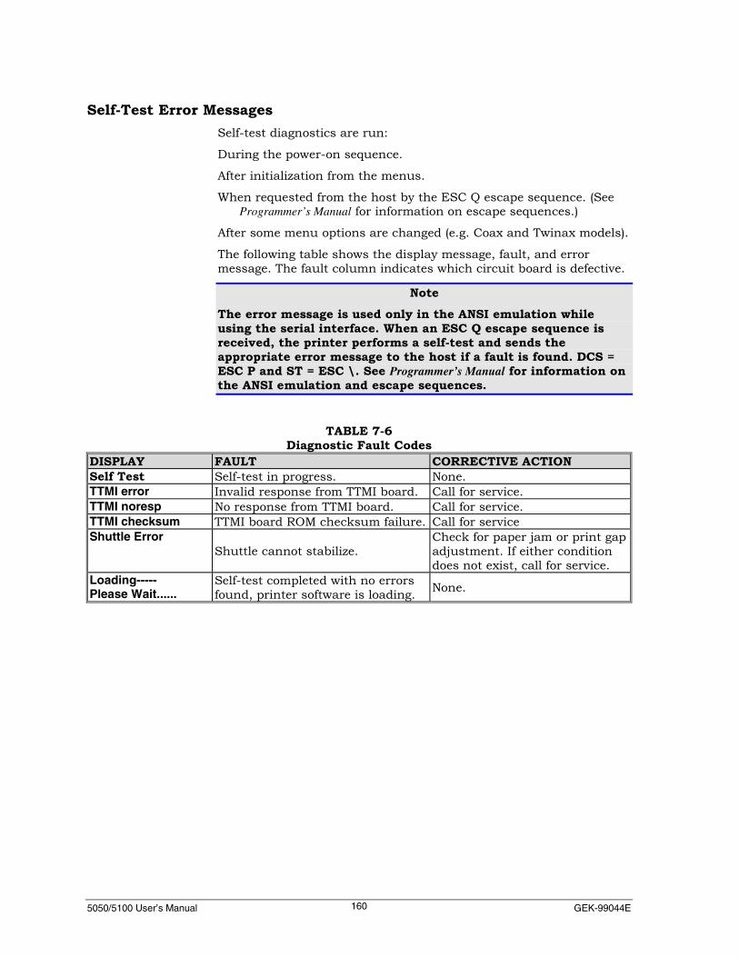
5050/5100 User’s Manual GEK-99044E160
Self-Test Error MessagesSelf-test diagnostics are run:
During the power-on sequence.
After initialization from the menus.
When requested from the host by the ESC Q escape sequence. (SeeProgrammer’s Manual for information on escape sequences.)
After some menu options are changed (e.g. Coax and Twinax models).
The following table shows the display message, fault, and errormessage. The fault column indicates which circuit board is defective.
NoteThe error message is used only in the ANSI emulation whileusing the serial interface. When an ESC Q escape sequence isreceived, the printer performs a self-test and sends theappropriate error message to the host if a fault is found. DCS =ESC P and ST = ESC \. See Programmer’s Manual for information onthe ANSI emulation and escape sequences.
TABLE 7-6Diagnostic Fault Codes
DISPLAY FAULT CORRECTIVE ACTIONSelf Test Self-test in progress. None.TTMI error Invalid response from TTMI board. Call for service.TTMI noresp No response from TTMI board. Call for service.TTMI checksum TTMI board ROM checksum failure. Call for serviceShuttle Error
Shuttle cannot stabilize.Check for paper jam or print gapadjustment. If either conditiondoes not exist, call for service.
Loading-----Please Wait......
Self-test completed with no errorsfound, printer software is loading. None.
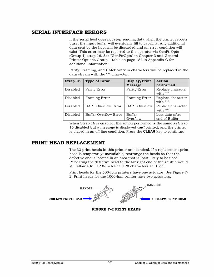
5050/5100 User’s Manual Chapter 7. Operator Care and Maintenance161
SERIAL INTERFACE ERRORSIf the serial host does not stop sending data when the printer reportsbusy, the input buffer will eventually fill to capacity. Any additionaldata sent by the host will be discarded and an error condition willexist. This error may be reported to the operator via GenPtrOpts(Group 1) strap 16. See “GenPtrOpts” in Chapter 3 and GeneralPrinter Options Group 1 table on page 184 in Appendix G foradditional information.
Parity, Framing, and UART overrun characters will be replaced in thedata stream with the “*” character.
Strap 16 Type of Error Display/PrintMessage
Actionperformed
Disabled Parity Error Parity Error Replace characterwith “*”
Disabled Framing Error Framing Error Replace characterwith “*”
Disabled UART Overflow Error UART Overflow Replace characterwith “*”
Disabled Buffer Overflow Error BufferOverflow
Lost data afterend of Buffer
When Strap 16 is enabled, the action performed is the same as Strap16 disabled but a message is displayed and printed, and the printeris placed in an off line condition. Press the CLEAR key to continue.
PRINT HEAD REPLACEMENTThe 33 print heads in this printer are identical. If a replacement printhead is temporarily unavailable, rearrange the heads so that thedefective one is located in an area that is least likely to be used.Relocating the defective head to the far right end of the shuttle wouldstill allow a full 12.8-inch line (128 characters at 10 cpi).
Print heads for the 500-lpm printers have one actuator. See Figure 7-2. Print heads for the 1000-lpm printer have two actuators.
FIGURE 7–2 PRINT HEADS
1000-LPM PRINT HEAD500-LPM PRINT HEAD
BARRELSHANDLE
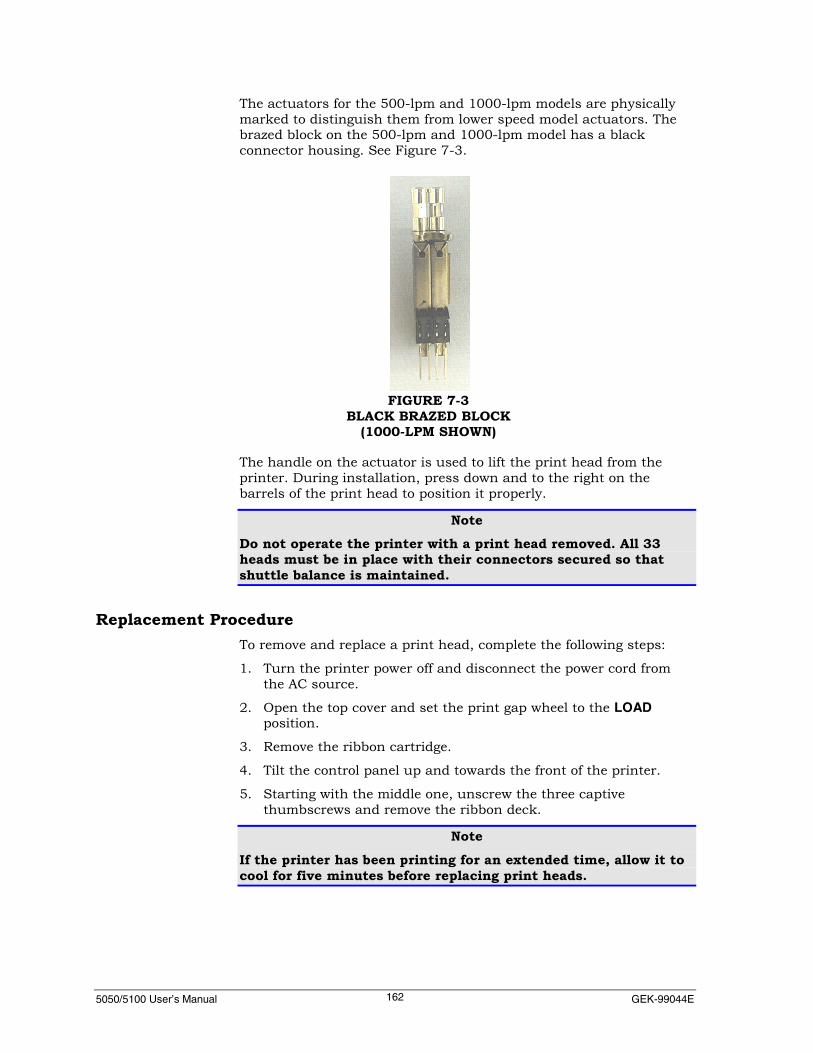
5050/5100 User’s Manual GEK-99044E162
The actuators for the 500-lpm and 1000-lpm models are physicallymarked to distinguish them from lower speed model actuators. Thebrazed block on the 500-lpm and 1000-lpm model has a blackconnector housing. See Figure 7-3.
The handle on the actuator is used to lift the print head from theprinter. During installation, press down and to the right on thebarrels of the print head to position it properly.
NoteDo not operate the printer with a print head removed. All 33heads must be in place with their connectors secured so thatshuttle balance is maintained.
Replacement ProcedureTo remove and replace a print head, complete the following steps:
1. Turn the printer power off and disconnect the power cord fromthe AC source.
2. Open the top cover and set the print gap wheel to the LOADposition.
3. Remove the ribbon cartridge.
4. Tilt the control panel up and towards the front of the printer.
5. Starting with the middle one, unscrew the three captivethumbscrews and remove the ribbon deck.
NoteIf the printer has been printing for an extended time, allow it tocool for five minutes before replacing print heads.
FIGURE 7-3BLACK BRAZED BLOCK
(1000-LPM SHOWN)

5050/5100 User’s Manual Chapter 7. Operator Care and Maintenance163
6. Remove the Allen wrench from the foam padding. See Figure 7-4.
7. Unscrew the two screws securing the print head cable cover forthe print head to be removed. See Figure 7-4. Unscrew the screwsuntil their ends are flush with the end of the cover.
NoteOn 500-lpm printers, the cable covers are attached in pairs.Three screws must be loosened to remove the covers.When removing print heads 6, 17, and 28 on a 1000-lpm printer,two cable covers must be removed. Remove covers 1 and 2 forprint head 6, covers 3 and 4 for print head 17, and covers 5 and6 for print head 28.
8. Remove the cable cover by pulling back on it while wiggling itfrom side to side. After it is disconnected, lift up on the back ofthe cover to clear the screws.
FIGURE 7-4 REPLACEMENT PROCEDURE (1 OF 3)
ACTUATOR NUMBERS
RIBBON SHIELD
ALLENWRENCH
PRINT HEADCABLE COVER
WRENCHSTORAGE
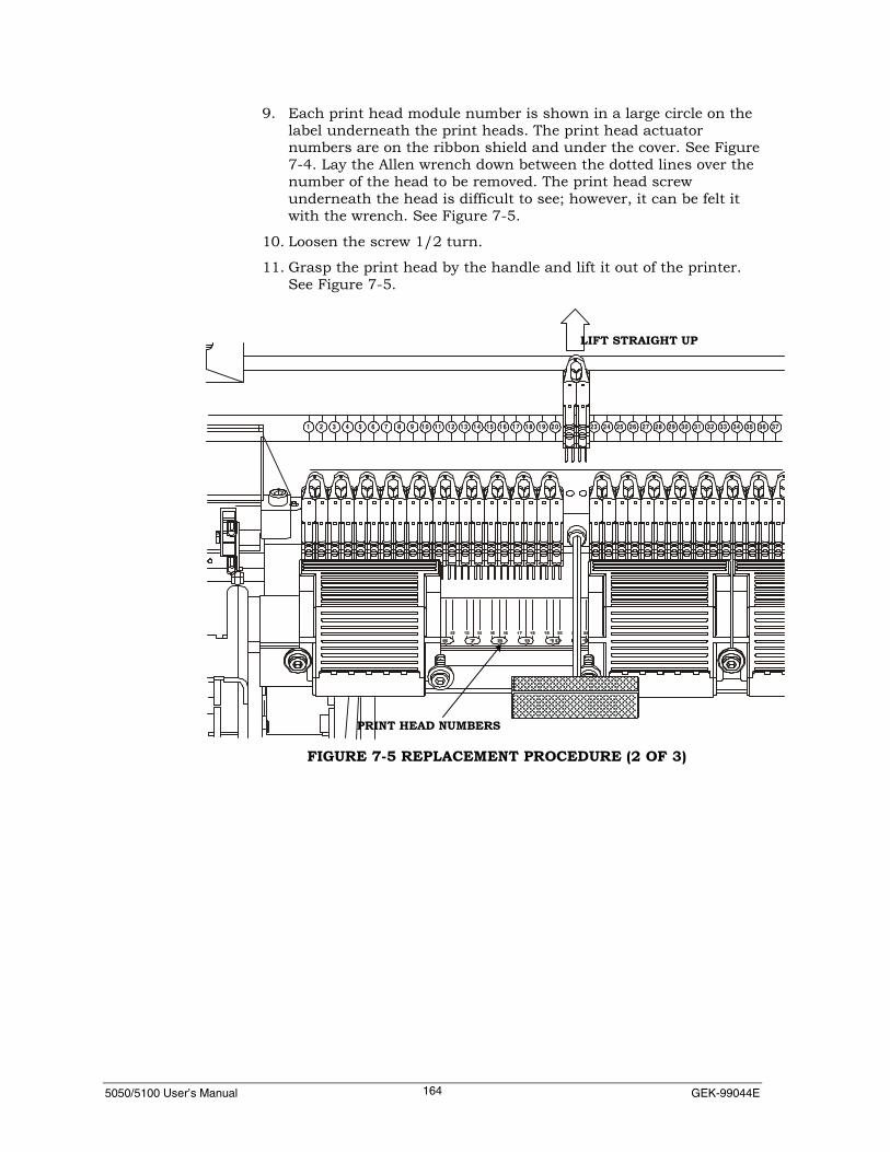
5050/5100 User’s Manual GEK-99044E164
9. Each print head module number is shown in a large circle on thelabel underneath the print heads. The print head actuatornumbers are on the ribbon shield and under the cover. See Figure7-4. Lay the Allen wrench down between the dotted lines over thenumber of the head to be removed. The print head screwunderneath the head is difficult to see; however, it can be felt itwith the wrench. See Figure 7-5.
10. Loosen the screw 1/2 turn.
11. Grasp the print head by the handle and lift it out of the printer.See Figure 7-5.
1 2 3 4 5 6 7 8 9 10 11 12 13 14 15 16 17 18 19 20 23 24 25 26 27 28 29 30 31 32 33 34 35 36 37
FIGURE 7-5 REPLACEMENT PROCEDURE (2 OF 3)
LIFT STRAIGHT UP
PRINT HEAD NUMBERS

5050/5100 User’s Manual Chapter 7. Operator Care and Maintenance165
12. Place the new print head over the print head screw. Press downand to the right on the barrels of the print head and tighten thescrew. See Figure 7-6.
NoteIf there is not enough or too much clearance for the new printhead, loosen the print head screws on all of the heads to the leftof the one being replaced. When the new print head is in place,tighten all print head screws starting with the new one andworking towards the left side of the printer. Keep each printhead snug against the print head immediately to the right.
13. Push the cable cover/connector over the connecting pins on theprint heads. Wiggle the cover from side to side while pushing theconnector onto the pins. When in place, press down on the end ofthe cover while tightening the cover screws.
14. Install the ribbon deck and a ribbon cartridge. Make sure thethumbscrews are tight on the ribbon deck.
15. Apply power and run the printer again to verify correct operation.
Resetting Print Head CountersThe printer keeps track of how many times each print head is firedduring printing and displays this information on a graph.
Counters should be reset only when a new print head has beeninstalled.
1 2 3 4 5 6 7 8 9 10 11 12 13 14 15 16 17 18 19 20 21 22 23 24 25 26 27 28 29 30 31 32 33 34 35 36 37
PRESS DOWN AND TO THERIGHT ON BOTH BARRELS
FIGURE 7-6 REPLACEMENT PROCEDURE (3 OF 3)
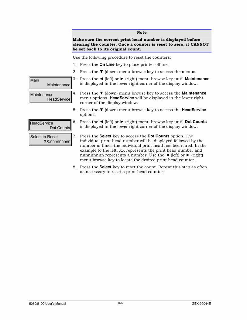
5050/5100 User’s Manual GEK-99044E166
NoteMake sure the correct print head number is displayed beforeclearing the counter. Once a counter is reset to zero, it CANNOTbe set back to its original count.
Use the following procedure to reset the counters:
1. Press the On Line key to place printer offline.
2. Press the ▼ (down) menu browse key to access the menus.
3. Press the ◄ (left) or ► (right) menu browse key until Maintenanceis displayed in the lower right corner of the display window.
4. Press the ▼ (down) menu browse key to access the Maintenancemenu options. HeadService will be displayed in the lower rightcorner of the display window.
5. Press the ▼ (down) menu browse key to access the HeadServiceoptions.
6. Press the ◄ (left) or ► (right) menu browse key until Dot Countsis displayed in the lower right corner of the display window.
7. Press the Select key to access the Dot Counts option. Theindividual print head number will be displayed followed by thenumber of times the individual print head has been fired. In theexample to the left, XX represents the print head number andnnnnnnnnn represents a number. Use the ◄ (left) or ► (right)menu browse key to locate the desired print head counter.
8. Press the Select key to reset the count. Repeat this step as oftenas necessary to reset a print head counter.
HeadServiceDot Counts
Select to ResetXX:nnnnnnnnn
MaintenanceHeadService
MainMaintenance
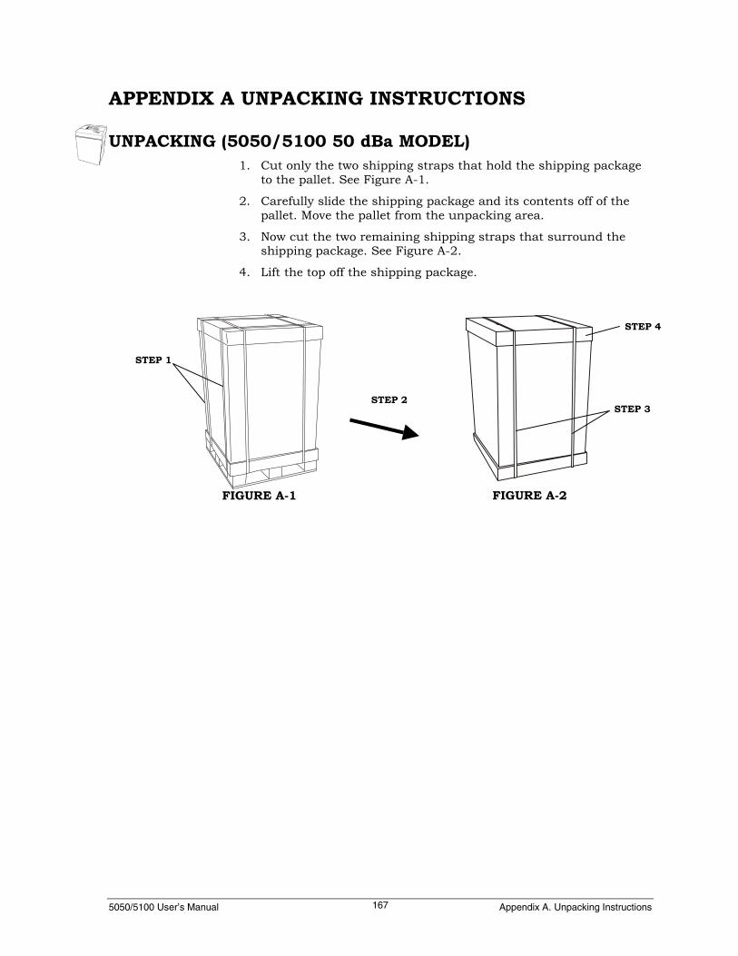
5050/5100 User’s Manual Appendix A. Unpacking Instructions167
APPENDIX A UNPACKING INSTRUCTIONS
UNPACKING (5050/5100 50 dBa MODEL)1. Cut only the two shipping straps that hold the shipping package
to the pallet. See Figure A-1.
2. Carefully slide the shipping package and its contents off of thepallet. Move the pallet from the unpacking area.
3. Now cut the two remaining shipping straps that surround theshipping package. See Figure A-2.
4. Lift the top off the shipping package.
STEP 2
FIGURE A-1 FIGURE A-2
STEP 4
STEP 3
STEP 1

5050/5100 User’s Manual GEK-99044E168
5. Remove the packing material from the top of the printer. SeeFigure A-3.
6. Lift out the single panel of the shipping package sleeve. SeeFigure A-3.
7. Now remove the remaining 3-sided package sleeve and thepacking material. See Figure A-3.
8. Cut the front and back corners of both sides of the shippingpackage base so that the cardboard will lay flat. See Figure A-4.
9. Cut the plastic bag free from the shipping blocks on each side(taking care to not scratch or cut the printer) and remove fromthe printer.
10. Tilt the printer slightly from the side where the cardboard was cutand kick the packing block (see figure A-4) out from under theprinter. Carefully lower the printer. Repeat to remove the packingblock from the opposite side.
STEP 5
STEP 6
STEP 7
FIGURE A-3
STEP 9
STEP 8
FIGURE A-4
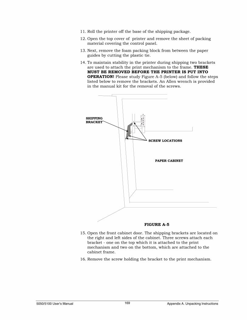
5050/5100 User’s Manual Appendix A. Unpacking Instructions169
11. Roll the printer off the base of the shipping package.
12. Open the top cover of printer and remove the sheet of packingmaterial covering the control panel.
13. Next, remove the foam packing block from between the paperguides by cutting the plastic tie.
14. To maintain stability in the printer during shipping two bracketsare used to attach the print mechanism to the frame. THESEMUST BE REMOVED BEFORE THE PRINTER IS PUT INTOOPERATION! Please study Figure A-5 (below) and follow the stepslisted below to remove the brackets. An Allen wrench is providedin the manual kit for the removal of the screws.
15. Open the front cabinet door. The shipping brackets are located onthe right and left sides of the cabinet. Three screws attach eachbracket - one on the top which it is attached to the printmechanism and two on the bottom, which are attached to thecabinet frame.
16. Remove the screw holding the bracket to the print mechanism.
SHIPPINGBRACKET
SCREW LOCATIONS
PAPER CABINET
FIGURE A-5

5050/5100 User’s Manual GEK-99044E170
17. Remove the two screws on the bottom of the shipping bracket.
NoteThe brackets and screws, as well as the Allen wrench can bereused if the printer is shipped to a new location at a futuredate.
Unpacking (5050/5100 55 or 60 dBa Model)1. Cut the shipping straps. See Figure A-6.
2. Lift the top off the shipping package. See Figure A-6.
3. Remove any items stored inside the shipping package. See FigureA-7
4. Remove the tray. See Figure A-7.
5. Remove the two pieces of packing material from the top of theprinter. See Figure A-7.
6. Lift out the front wall of the shipping sleeve. See Figure A-7.
STEP 2
STEP 1
FIGURE A-6
STEP 3 AND 4
STEP 5
STEP 6
FIGURE A-7

5050/5100 User’s Manual Appendix A. Unpacking Instructions171
7. Remove the packing material and box containing the paperhandling system from in front of the printer. See Figure A-8.
8. Remove the remaining portion of the shipping package sleeve. SeeFigure A-8.
9. Remove the ribbon cartridge box and the packing material fromthe rear of the printer. See Figure A-9.
STEP 8
STEP 7
FIGURE A-8
STEP 9
PLACE FOOT HEREDURING STEP 10
FIGURE A-9
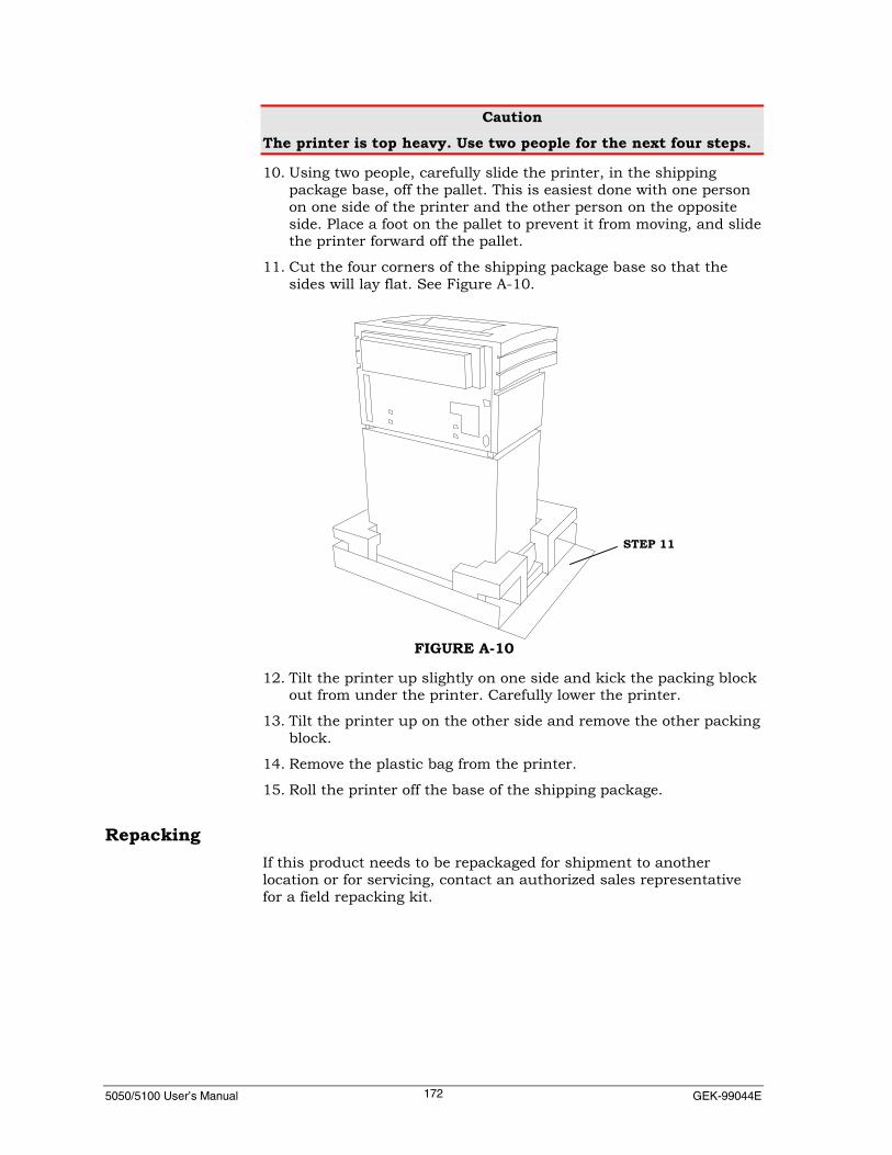
5050/5100 User’s Manual GEK-99044E172
CautionThe printer is top heavy. Use two people for the next four steps.
10. Using two people, carefully slide the printer, in the shippingpackage base, off the pallet. This is easiest done with one personon one side of the printer and the other person on the oppositeside. Place a foot on the pallet to prevent it from moving, and slidethe printer forward off the pallet.
11. Cut the four corners of the shipping package base so that thesides will lay flat. See Figure A-10.
12. Tilt the printer up slightly on one side and kick the packing blockout from under the printer. Carefully lower the printer.
13. Tilt the printer up on the other side and remove the other packingblock.
14. Remove the plastic bag from the printer.
15. Roll the printer off the base of the shipping package.
RepackingIf this product needs to be repackaged for shipment to anotherlocation or for servicing, contact an authorized sales representativefor a field repacking kit.
STEP 11
FIGURE A-10

5050/5100 User’s Manual Appendix B. Paper Specifications173
APPENDIX B PAPER SPECIFICATIONSThe printer is designed to use edge-punched (sprocket-fed) fanfoldpaper. See diagram below. multipart forms should be free of staplesor stitching and preferably held together with glue or self-crimpingtechniques. They need to be of uniform thickness from side-to-side.In the case of special forms and gummed labels, it is best to consult aforms supplier for help in selecting the best forms construction andto try a sample to ensure satisfactory operation. The chart on thenext page lists forms that should provide satisfactory performance.
Paper widths from 3 inches (76.2 mm) to 16.54 inches (420.1 mm)and form lengths from 0.3 inch (8.4 mm) to 22 inches (559 mm) canbe accommodated. Fanfolds between 5.5 and 12 inches (139.7 and304.8 mm) apart are recommended.
NoteHigh humidity may cause unsatisfactory paper feeding andhandling. Low humidity may cause static buildup. Make sure youtest how well the forms feed under various ambient conditions.Some recycled papers have a higher content of dust and debris,which may require more frequent cleaning of the printer.
The most satisfactory performance from the printer can be achievedwith paper of the recommended weights as shown below.
RECOMMENDED PAPER WEIGHTSNumber of Parts Recommended
Paper WeightWeight of CarbonInsert Sheet
1 15 lb (56 g/m2)2, 3, or 4 13.5 lb (50 g/m2) 5 lb (19 g/m2)5 or 6 12 lb (45 g/m2) 5 lb (19 g/m2)Recommended maximum weight for single-ply paper is 24 lb. (90g/m2). Maximum forms thickness should not exceed 0.025 inches(0.613 mm). Printing materials up to 125# Tag (226 g/m2) or 110#Index (199 g/m2) can be handled.
0.50 IN. (12.70 MM)
0.25 IN. (6.35 MM)
0.156 IN. (3.97 MM)
FIGURE B-1 SPROCKET HOLE DETAILS

5050/5100 User’s Manual GEK-99044E174
Company Catalog Number DescriptionAvery 4162 Clear Label, One-wide 3 1/2" X 15/16"
J21147 24-lb White Wove Envelope with Keen EdgeJ13706 24-lb White Wove EnvelopeJ21105 24-lb Ivory Laid Textured Envelope8530SG One-wide Tab Card, Computer Punch Card1530SG Two-wide Tab Card, Computer Punch Card1412T, 1412TC One-part 11" X 14 7/8" 15-lb1412T, 1412RH Two-part 11" X 14 7/8" 15-lb1412T, 1412TQ,1412RH
Three-part 11" X 14 7/8" 15-lb
1412T, 1412TE Four-part 11" X 14 7/8" 15-lb1412T Five-part 11" X 14 7/8" 15-lb1412T, 1412TQ,1412NP
Six-part 11" X 14 7/8" 15-lb
TC7 110-lb Time Cards21022 20-lb Laid Textured13557 Six-part Self-Mailer13060 Seven-part Universal Mailer13086 Two-wide 3" X 5" Card 100-lb. White Tag Stock29264 Mini-printer Label 3 1/2" X 15/16"1410Q Two-part 14 7/8" X 11"1410CKP One-part 14 7/8" X 11"8510 One-part 8 1/2" X 11"8512TQ Three-part 8 1/2" X 11"8512TQ Six-part 8 1/2" X 11"13078 3" X 5", 100-lb. White Tag Stock9510J Four-part 9 1/2" X 11"9510CK, 9510J,9510CJ
One-part 9 1/2" X 11"
1182T One-part 113/4" X 8 1/2"1280J, 1280CK One-part 12" X 8 1/2"1482TA, 1488TH One-part 14 7/8" X 8 1/2"NNSY 4430/26 Four-part 9 1/2" X 11"P1-9511-15-00 One-part 9 1/2" X 11" 15-lbP1-9511-20-00 One-part 9 1/2" X 11" 20-lb13805 One-part 20-lb.28084 Label, One-wide 3 1/2" X 15/16"28118 Label, Two-wide 3 1/2" X 15/16"28142 Label, Three-wide 3 1/2" X 15/16"
Moore
28183 Label, Four-wide 3 1/2" X 15/16" 2-10-L6 6-part Self-Mailer6240174082 8-1/2" X 11" Carbonless 5-part
NCR
211093 Single-part 11" X 14 7/8" 15-lb

5050/5100 User’s Manual Appendix C. Considerations for Operation175
APPENDIX C CONSIDERATIONS FOR OPERATIONVoltage: 120 VAC and 240 VAC ±15% auto range seeking.
Frequency: 48 to 65 Hz.
Power Consumption:
500-LPM 1000-LPMIdle 35 Watts 35 WattsPrinting 213 Watts 350 Watts
Dissipated Power (maximum):
500-LPM 400 Watts = 1370 BTU/hour1000-LPM 524 Watts = 1795 BTU/hour
Weight:
Cabinet Model Unboxed Boxed
5050/5100 (55 dBa) 175 lbs.97.3 kg
220 lbs.99.7 kg
5050/5100 (50 dBa) 295 lbs.133.8 kg
340 lbs.154.2 kg
5050/5100 (60 dBa) 169 lbs.214 lbs.
76.8 kg97.3 kg
Overall size:
Cabinet Model Physical Size (HxWxD)
5050/5100 (55 dBa) 42 x 26.5 x 25 in.1077 x 679 x 635 mm
5050/5100 (50 dBa) 42 x 27 x 29 in.1077 x 686 x 737 mm
5050/5100 (60 dBa) 39 x 26.6 x 25 in.991 x 679 x 635 mm
An additional 20 inches (50.8cm) of clearance is required in frontof the printer to open the pedestal door.
An additional 22 inches of clearance is required in the rear of the5050/5100 (50 dBa) Cabinet Model printer to open the rearcabinet door.
5050/5100 User’s Manual GEK-99044E176
Paper Handling:
5050/5100 (55 dBa) Cabinet Model – allow an additional 10inches of clearance in the rear of the printer for the paperhandling shelf option.
Operating Environment:
Temperature 39 to 104° F4 to 40° CHumidity 15 to 90% noncondensing
NoteFor UK installations, a 10-amp fuse must be installed on themains lead.

GEK-99044E Appendix D. Parts, Accessories, ConsumablesAnd Options
177
APPENDIX DPARTS, ACCESSORIES, CONSUMABLES ANDOPTIONS
The items listed below are available from an authorized GENICOMdistributor, service agent, or from GENICOM headquarters at thefollowing address:
GENICOM CorporationParts Sales1 Genicom DriveWaynesboro, Virginia 22980-19991-800-535-4364FAX: (540) 949-1890Electronic Bulletin Board: (540) 949-1576
Check for current printer drivers and the updated replacement andspare part listings.
Information is also available on the Internet at the following URL:
http://www.genicom.com/drivers/index.htmWhen ordering, specify description, part or catalog number, andquantity desired. Have the model number of the printer available.
Ribbon Part Description Part or Catalog Number5050/5100 Ribbon Cartridge (50 M) 4A0040B02
5050/5100 Ribbon Cartridge (75 M) 4A0040B05
5050/5100 Ribbon CartridgeFast Drying – Special Applications 4A0040B11
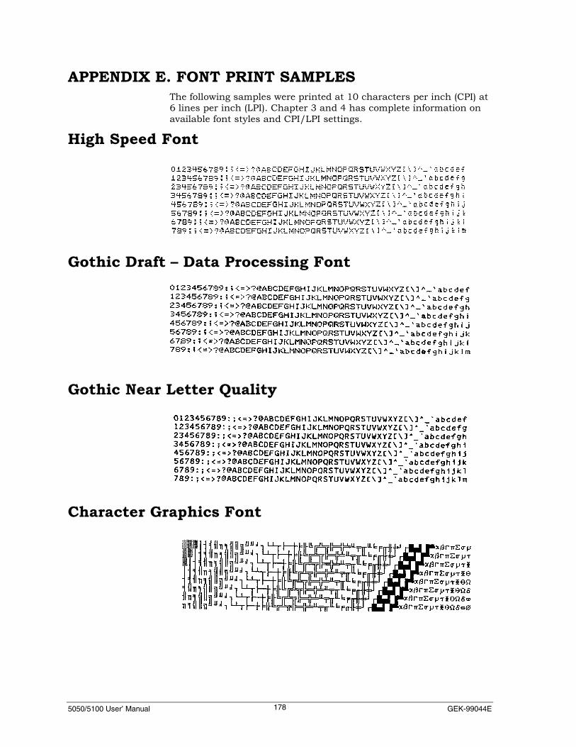
5050/5100 User’ Manual GEK-99044E178
APPENDIX E. FONT PRINT SAMPLESThe following samples were printed at 10 characters per inch (CPI) at6 lines per inch (LPI). Chapter 3 and 4 has complete information onavailable font styles and CPI/LPI settings.
High Speed Font
Gothic Draft – Data Processing Font
Gothic Near Letter Quality
Character Graphics Font

5050/5100 User’s Manual Appendix E. Font Print Samples179
Correspondence Font(BETTER QUALITY THAN DRAFT-BETTER SPEED THAN NLQ)
OCR-A Font
OCR-B Font
Courier NLQ Font
Italic NLQ Font

5050/5100 User’ Manual GEK-99044E180
High Speed 2
Canadian Pst
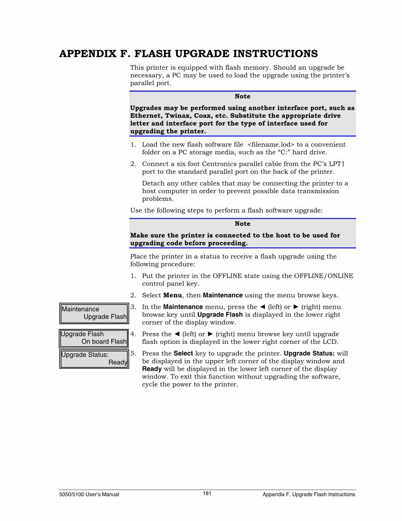
5050/5100 User’s Manual Appendix F. Upgrade Flash Instructions181
APPENDIX F. FLASH UPGRADE INSTRUCTIONSThis printer is equipped with flash memory. Should an upgrade benecessary, a PC may be used to load the upgrade using the printer’sparallel port.
NoteUpgrades may be performed using another interface port, such asEthernet, Twinax, Coax, etc. Substitute the appropriate driveletter and interface port for the type of interface used forupgrading the printer.
1. Load the new flash software file <filename.lod> to a convenientfolder on a PC storage media, such as the “C:” hard drive.
2. Connect a six foot Centronics parallel cable from the PC’s LPT1port to the standard parallel port on the back of the printer.
Detach any other cables that may be connecting the printer to ahost computer in order to prevent possible data transmissionproblems.
Use the following steps to perform a flash software upgrade:
NoteMake sure the printer is connected to the host to be used forupgrading code before proceeding.
Place the printer in a status to receive a flash upgrade using thefollowing procedure:
1. Put the printer in the OFFLINE state using the OFFLINE/ONLINEcontrol panel key.
2. Select Menu, then Maintenance using the menu browse keys.
3. In the Maintenance menu, press the ◄ (left) or ► (right) menubrowse key until Upgrade Flash is displayed in the lower rightcorner of the display window.
4. Press the ◄ (left) or ► (right) menu browse key until upgradeflash option is displayed in the lower right corner of the LCD.
5. Press the Select key to upgrade the printer. Upgrade Status: willbe displayed in the upper left corner of the display window andReady will be displayed in the lower left corner of the displaywindow. To exit this function without upgrading the software,cycle the power to the printer.
MaintenanceUpgrade Flash
Upgrade Status:Ready
Upgrade FlashOn board Flash
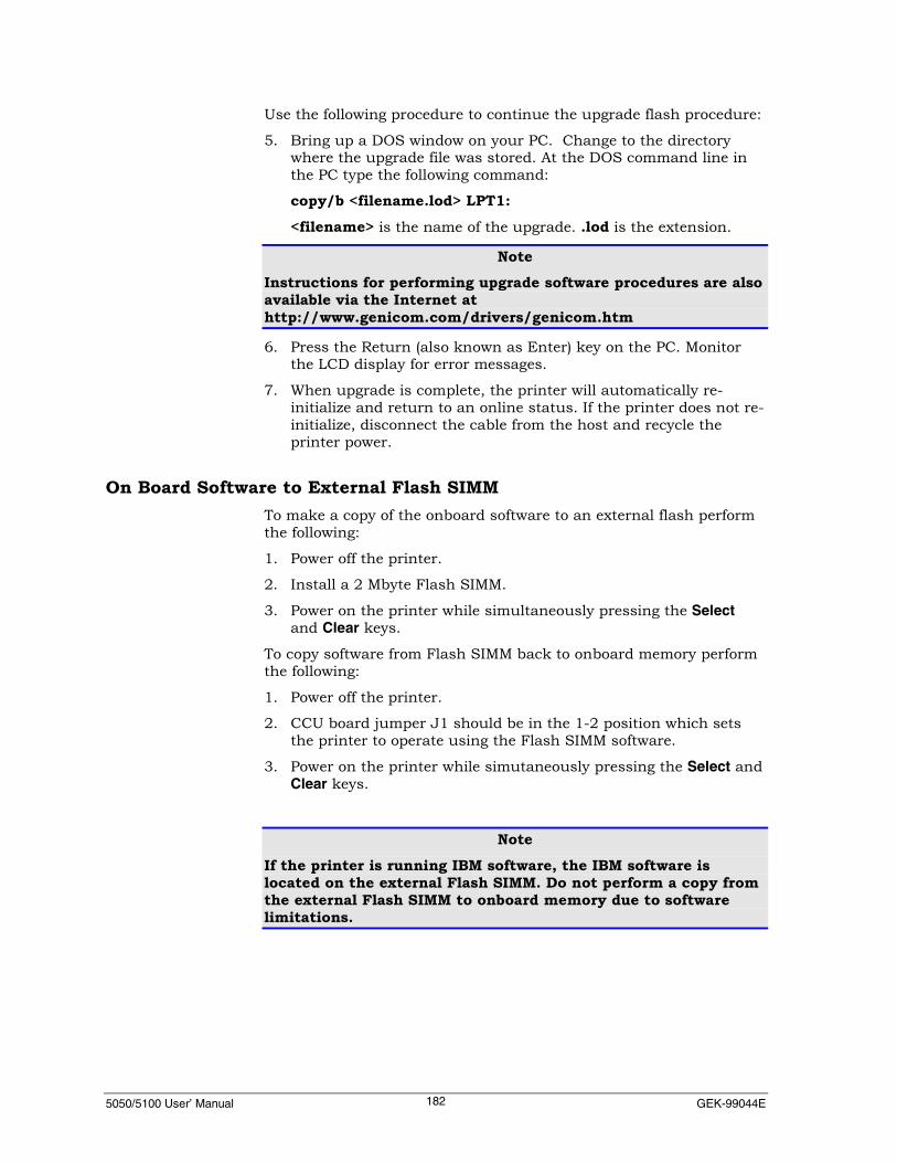
5050/5100 User’ Manual GEK-99044E182
Use the following procedure to continue the upgrade flash procedure:
5. Bring up a DOS window on your PC. Change to the directorywhere the upgrade file was stored. At the DOS command line inthe PC type the following command:
copy/b <filename.lod> LPT1:<filename> is the name of the upgrade. .lod is the extension.
NoteInstructions for performing upgrade software procedures are alsoavailable via the Internet athttp://www.genicom.com/drivers/genicom.htm
6. Press the Return (also known as Enter) key on the PC. Monitorthe LCD display for error messages.
7. When upgrade is complete, the printer will automatically re-initialize and return to an online status. If the printer does not re-initialize, disconnect the cable from the host and recycle theprinter power.
On Board Software to External Flash SIMMTo make a copy of the onboard software to an external flash performthe following:
1. Power off the printer.
2. Install a 2 Mbyte Flash SIMM.
3. Power on the printer while simultaneously pressing the Selectand Clear keys.
To copy software from Flash SIMM back to onboard memory performthe following:
1. Power off the printer.
2. CCU board jumper J1 should be in the 1-2 position which setsthe printer to operate using the Flash SIMM software.
3. Power on the printer while simutaneously pressing the Select andClear keys.
NoteIf the printer is running IBM software, the IBM software islocated on the external Flash SIMM. Do not perform a copy fromthe external Flash SIMM to onboard memory due to softwarelimitations.

5050/5100 User’s Manual Appendix G. Desription of Strapping Options183
APPENDIX G DESCRIPTION OF STRAPPING OPTIONSThis appendix contains descriptions for firmware strap settings,which are changed using the Set Up menu. See “Using the Set UpMenu” in Chapter 5 for procedures to enable/disable an option.

5050/5100 User’ Manual GEK-99044E184
GENERAL PRINTER OPTIONS DEFINITIONSGroup 1
Straps Function If Active If Inactive
01 TOF set moveforward Use forward motion. Use reverse motion.
02 Define Paper Low Paper out fault. Paper low fault.
03 Deselect on PaperLow Enable if 02 is enabled. Disabled.
04 Auto low paper printto end of last sheet Override 02 and 03. Disabled.
05 Paper Jam Fault Unreported. Reported.
06 Reverse papermotion Permitted on Paper Low. Causes Paper Out Fault.
07 Autoview feature Enabled. Disabled.
08 Enable TTMI kickstart Enabled. Disabled.
09 Truncate slews atTOF Enabled. Disabled.
10 Ribbon weld fault. Disabled Enabled.
11 Descending draftcharacters Descending Non-descending.
12 Descending NLQcharacters Descending. Non-descending.
13 CPI reset at fontchange CPI reset to 10 cpi. CPI retained.
14 Derive 12 cpi From 10cpi. From 13 cpi.
15 Derive 15 cpi From 16 cpi. From 13 cpi.
16 Enable Serial I/Ferror print
Display/print serial I/Ferrors. “*” for Serial I/F errors.
17 Alarm LED Reflectsonline/local/fault Reflects faults only.
18-32 Reserved for future use.

5050/5100 User’s Manual Appendix G. Desription of Strapping Options185
Group 2Straps Function If Active If Inactive
01 Repeat bell duringfault Repeated bell. Single bell.
02 Disable bell Disabled. Enabled.
03 Enable slashed zero. Slashed zero Normal zero.
04 Power-up state Online state. Local state.
05 Power-up in last state Use last state. Use strap 4.
06 Menu exit condition Exit after 1 minute. No exit on inactivity.
07 Top-of-Form control Disable TOF on remote. Enable TOF on remote.
08 Received DC1-DC3operation Select/Deselect.. No Select/Deselect..
09Substitute EUROcharacter (8859-X at0XA4)
Substitute EUROcharacter. No EURO substitution.
10 Page mode imaging Enabled. Disabled.
11 Paper at top of BarCode after printing Top of BC after print.. No position change after BC.
12 Staggered Barcodes Enable. Disable.
13Paper at top ofOVERSIZE afterprinting
Top of Oversize afterprint.
No position change afterOversize.
14Substitute EUROcharacter (all pages at0XFE - Windows)
Substitute EUROcharacter. No EURO substitution.
15 Rotate Bar Code Mode Rotate relative toorientation. Rotate about portrait x, y.
16 Force bar code newpage
Move to new page if BC> bottom margin. Disable forced new page.
17 Multi-TierOptimization Sparse data. Dense Data.
18 Disable OverStrike Disable. Enable.
19
Function to sync thecurrent form form froman interface switch tothe true physicalposition on the page
Enable. Disable.
20Allow function of strap19 on the sameinterface if a timeoutoccurred.
Will force a new form Will not force a new Form.
21 Buffering Enables reducedbuffering. Normal buffering is used.
22-32 Reserved for future use.

5050/5100 User’ Manual GEK-99044E186
LEGACY PARALLEL HARDWARE STRAP DEFINITIONSStrap meanings are the same for Centronics, DP (Short) and DP(Long). However, the straps are set individually for each. If Centronicsand DP (Short) are both installed, each must be setup separately.

5050/5100 User’s Manual Appendix G. Desription of Strapping Options187
I/F Hardware StrapsH Bits01-32 Function If Enabled If Disabled
01 Prime High = Buffer Clear. Low = Buffer Clear.
02 Interrupt On all Control Codes.Disabled on all Control Codes,except LF, VT, FF, CR, DC1 andDC3.
03 DEL Does not cause an Interrupt. Causes an Interrupt.04 DEL Does not cause Prime. Causes Prime.
05-06 Reserved.07 Underline character Treated as CR. Printed.08 PI Lead Causes Interrupt. Does not cause Interrupt.
09 ACK leadDoes not reflectONLINE/LOCAL status. 05must be enabled.
Reflects ONLINE/LOCAL status.
10 Characterconversion to space. Enabled. (See 41-48.) Disabled.
11 CR Not decoded. Generate an Interrupt.12 FF Not decoded. Generate an Interrupt.13 LF Not decoded. Generate an Interrupt.14 VT Not decoded. Generate an Interrupt.15 DC3 Not decoded. Generate an Interrupt.16 DC1 Not decoded. Generate an Interrupt.17 Busy Does not reflect ACK. Reflects ACK.
18 Busy/Demand percharacter. Enabled. Disabled.
19 Software control ofBusy. Disabled Enabled.
20 BusyDoes not reflect(ONLINE/LOCAL) FAULT/POstatus.
Reflects (ONLINE/LOCAL)FAULT/PO status.
21 Busy Does not reflect (FAULT)ONLINE/LOCAL status.
Reflects (FAULT) ONLINE/LOCALstatus.
22 Busy Does not reflect (PO)ONLINE/LOCAL/PO status.
Reflects (PO) ONLINE/LOCAL/POstatus.
23 ACK Does not reflect PO. Reflects PO.24 ACK Does not reflect FAULT. Reflects FAULT.25 Data leads 0-7 are active high. 0-7 are active low.26 Busy is active High. Low.27 PI is active High. Low.28 PI Enabled. Disabled.29 STB is active High. Low.30 SELECT is active High. Low.31 PO is active High. Low.32 FAULT is active High. Low.
H Bits33-64 Function If Enabled. If Disabled
33 Demand delay. Disabled. Enabled.34 35 DelayDisable Disable None
Disable Enable 1 µsec
Enable Disable 2 µsec34-35 Set ACK delay from
Strobe.
Enable Enable 3 µsec
36 37 WidthDisable Disable None
Disable Enable 1 µsec
Enable Disable 2 µsec36-37 Set ACK Pulse
Width.
Enable Enable 3 µsec
38-40 Reserved.
41-48 Used with strap 10 to select space character substitution. 41 corresponds with Bit 1 of thecharacter code.
49-64 Reserved.

5050/5100 User’ Manual GEK-99044E188
LEGACY PARALLEL SOFTWARE STRAP DEFINITIONSI/F Software Straps
Bits01-32 Function If Enabled If Disabled
01-03 Reserved for future use.
04 Prime on Select. Disabled. Enabled.
05 No Fault on PO or Deselect. Disabled. Enabled.
06-07 Reserved for future use.
08 8 bit Data. Enabled. Bit 8 equals 0.
09-32 Reserved for future use.
Bits33-64 Function If Enabled If Disabled
33-39 Reserved for future use.
40 Parallel timeout. Disabled. Enabled.
41-64 Reserved for future use.

5050/5100 User’s Manual Appendix G. Desription of Strapping Options189
EMULATION OPTION DESCRIPTIONSANSI (4800)
Options Meaning if Active If Active If Inactive01 Oversize and Bar code Select via SI/SO. No selection via
SI/SO02 RCC mode Reset RCC mode. Set RCC mode.
03 ESC C control Disable ESC C sequence. Reset when ESC Cis received.
04 Reserved.
05 Reserved.
06 GENCIC control Set (80-8F as control). Reset (80-9F perGENCS2).
07 GENCS2 control Set (80-9F, 15, print). Reset (80-9Fignore)
08 Line grid control LF = next LPI grid LF = LF
09 Dbl strike/shadowcontrol Double Strike Shadow.
10 CharacterGraphics/Postnet
Char Graphics in SCR[2]esc[12m.
Canad. Postnet inSGR[2] esc[12m.
11-32 Reserved.
ANSI (4410)Options Function If Active If Inactive01 SI/SO selects Oversize
and Bar code Select.. Ignore SI/SO.
02 Reserved.
03 ESC C control Disable ESC C sequence. Reset when ESC C is received.
04 Reserved.
05 Reserved.
06 GENCIC control Set (80-8F as control). Reset (80-9F per GENCS2).
07 GENCS2 control Set (80-9F, 15, print). Reset (80-9F ignore).
08 Line grid control LF = next LPI grid. LF = LF.
09 Dbl strike/shadowcontrol Double Strike Shadow.
10 CharacterGraphics/Postnet
Char Graphics in SCR[2]esc[12m.
Canadian. Postnet in SGR[2]esc[12m.
11 Bit 8 control 8th bit is alternative font.. 8th bit selects 256 characteroffset.
12 Reserved.13 14 15 16 SGR Font NameDisable Disable Disable Disable 10 Gothic Draft
Enable Disable Disable Disable 11 Gothic Draft
Disable Enable Disable Disable 12 Char Graphics
Enable Enable Disable Disable 13 Gothic NLQ
Disable Disable Enable Disable 14 Courier NLQ
Enable Disable Enable Disable 15 High Speed
Disable Enable Enable Disable 16 OCR-A NLQ
Enable Enable Enable Disable 17 OCR-B NLQ
Disable Disable Disable Enable 18 Italics NLQ
13-16 Alternate FontSelection Defaults
Enable Disable Disable Enable 19 Correspondence
17-32 Reserved

5050/5100 User’ Manual GEK-99044E190
Proprinter III XLOptions Function If Active If Inactive01 RESERVED (Slashed
Zero)Copy of ENG_OP_SLASH_ZERO from GenPtrOptsStrap 3).
02 Line Length 8 inches. 13.6 inches.
03 Condensed Print 12 cpi. 20 cpi.
04 Initial Code page Multinational. USA.
05 Character Set Selectdefault Character set 2. Character set 1.
06 Default Form Length 12” Form. 11” Form.
07 Reserved Copy of AUTOLF_ON_CR from Print ControlMenu..
08 Reserved Copy of AUTOCR_ON_VM from Print ControlMenu.
09 NLQ II Can use mulitnational. No multinational.
10 Reserved Copy of AUTOCR_ON_LF from Print ControlMenu..
11 Reserved Copy of AUTOCR_ON_FF from Print Control Menu.
12 Esc I Ignore Esc I command Process Esc Icommand
13 Simulate 136 Simulate 136 columns. Standard 132columns.
14-32 Reserved

5050/5100 User’s Manual Appendix G. Desription of Strapping Options191
EPSON FX286eOptions Function If Active If Inactive01 Condensed
Print. Enabled Disabled.
02 Italics fontcontrol
Codes 128-255 are CodePage. Codes 128-255 are Italics.
03 Default PrintQuality
Default print quality isNLQ. Default print quality is draft.
04 Default PerfSkip 1 inch perf skip default. No perf skip default.
05 Ignore Esc I Ignore Esc I command Process Esc I command
06 136 Col. Simulate 136 Columns Standard 132 Columns.
07-32 Reserved

5050/5100 User’ Manual GEK-99044E192
Printronix PseriesOptions Function If Active If Inactive01 Overstrike Enabled. Disabled.
02 ACK selects LPI for 1 line 10.3 LPI. 8 LPI.
03 VFU load PI required for VFU load. No PI required for VFUload.
04 Defines codes 80 to 9F 80 to 9F hex are printable. 80 to 9F hex arecontrol codes.
05 Backspace = Backspace. = Double High.
06-32 Reserved.
Printronix P300/600Options Function If Active If Inactive01 Edit Line (Carriage Return) = Carriage Return. Edit mode.
02 Restrict LPI To 8. Non-restricted LPI.
03-12 Reserved.
13 14 15 16 SGR FontName
Disable Disable Disable Disable 10 GothicDraft
Enable Disable Disable Disable 11 GothicDraft
Disable Enable Disable Disable 12 CharGraphics
Enable Enable Disable Disable 13 GothicNLQ
Disable Disable Enable Disable 14 CourierNLQ
Enable Disable Enable Disable 15 HighSpeed
Disable Enable Enable Disable 16 OCR-ANLQ
Enable Enable Enable Disable 17 OCR-BNLQ
Disable Disable Disable Enable 18 ItalicsNLQ
13-16 Alternate Font SelectionDefaults
Enable Disable Disable Enable 19 Correspondence
17-32 Reserved
Dec LG PlusOptions Function If Active If Inactive01 Unsolicited Reporting Enabled (See strap S-2). Disabled (default).
02 Unsolicited status report size Extended unsolicitedreports.
Brief unsolicitedreports. (default).
03 User Preference = Latin 9 (Euro Ready) = DEC Supplemental(default).
04-32 Reserved.
Dec PPL3Options Function If Active If Inactive01 ISO Latin9 Enabled. Disabled.
02-32 Reserved.

5050/5100 User’s Manual Appendix H. Interface, Emulation and Filter Information193
APPENDIX H.INTERFACE, EMULATION AND FILTERINFORMATION
PRINTER INTERFACES
Parallel and Serial InterfacesThe printer has bi-directional IEEE-1284, RS-232 serial and RS-422balanced voltage serial interfaces as standard. The RS-232 and RS-422 options share the same 25-pin, D connector. An additional twooptional interfaces may be added, which can include Ethernet, IBMTwinax/Coax, Data Products Long Line, Data Products Short Line,and Legacy Centronics. See Figure 2-2 on page 4 for the location ofthe optional interface slots.
All of the installed interfaces are active in the default Multsourcesetting of the Select I/F menu (under Set Up Menu | I/F Settings).The exception is the necessary selection of either RS-232 (default) orRS-422 options as the serial interface. If desired, selecting only oneinstalled interface causes the printer to ignore other data sourcesthat may be connected to the printer.
Each interface has its own input buffer. If the filters are enabled,each enabled filter represents 16K bytes of additional buffer capacityin series with the associated interface buffer.
Multisource TimeoutIn the Multisource setting, data is printed from the first port at whichdata is received. When no further data is received at that port, after aperiod of seconds, other ports are serviced on a first-come, first-servebasis. This period of time may be adjusted via the Delay Secondsoption located in Set Up Menu | I/F Setting | Multisource. See page72 for instructions to modify this setting. The default is threeseconds.
IEEE 1284 Bi-directional Parallel PortThe parallel port is IEEE 1284 nibble-mode compliant. The standardminimum bi-directional function is used to report make and model to1294-compliant hosts. A plug-and-play system such as Windows®uses this information to check for the appropriate printer driver. Toa non plug-and-play operating system, such as a traditionalCentronics host, the parallel port appears to be a traditionalCentronics port. The protocol is Busy-by-Character and ACK duringbusy. The input buffer size is fixed at 8.2K bytes, but any filterswhich have been enabled and associated with this port represents16K bytes additional buffer capacity per filter.
Historically, line printers enabled a multitude of parallel-port user-adjustments. IEEE-1284 compliance, however, imposes constraints.For this reason, the only characteristic of this port, which is user-

5050/5100 User’s Manual GEK-99044E194
controlled is whether the nFAULT signal is true on a paper-outcondition. The default is true. To change signal polarities such asACK delay, ACK duration or other previously adjusted settings, theoptional Legacy Centronics interface needs to be installed.
Parallel Interface Pin AssignmentsThe parallel interface data cable accepts a 36-pin male connector(Amphenol Part No. 554950-1 or equivalent.) The maximumrecommended length of cable is 10 feet. Selecting a high quality cablewill prevent problems such as improper grounding and/or shielding.Note that the “n” prefix means that a signal is negative-true.
PinCompatibility ModeSignal Name
Compatibility ModeSource
Nibble ModeSignal Name
1 NStrobe Host2 Data 1 Host3 Data 2 Host4 Data 3 Host5 Data 4 Host6 Data 5 Host7 Data 6 Host8 Data 7 Host9 Data 8 Host10 nACK Printer PtrClock11 Busy Printer PtrBusy12 Paper Empty Printer AckDatReq13 Select Printer Xflag14 Host Busy16 Signal Ground17 Chasis Ground18 +5V Printer Peripheral Logic High31 nPRIME Host32 nFAULT Printer nDataAvail36 IEEE-1284 Active
36-pin CENTRONICSConnector

5050/5100 User’s Manual Appendix H. Interface, Emulation and Filter Information195
Parallel Interface Timing
Legend Description MicrosecondsA Data Setup 0 minumumB nStrobe width 0.1 minumumC Data Hold 0 minimumD nAck width 0.68E Busy delay 0.2F Busy duration nStrobe width + 0.9 typical
Since the (synchronous) Busy duration is a function of nStrobe, the maximum rate of dataexchange depends on the host’s nStrobe width. The measured rate is 122 KB/sec for a one-thousand-character burst using a 1.5 microsecond nStrobe.
RS-232 Serial InterfaceThis interface supports baud rates from 1200 to 38,400. A 38, 400baud rate corresponds to 3840 characters per second assuming aten-bit character frame. A 1000-lpm printer can render about 2200characters per second printing resident characters in a high-speedtext mode. Under such circumstances, a baud rate slower than38,400 will not enable the rated speed of the printer. During one-bit-per-dot operation, graphics transfers such as used by ANSI,Proprinter, and Epson emulations, the bytes required to descibe aline of print can increase by a factor of five or more.
The serial input buffer is 32K bytes. The high trip point is adjustablefrom the Set Up Menu in 1% increments. The default is 80%. Anyfilters that have been enabled that are associated with this portrepresent 16K bytes of additional buffer capacity per filter.
BCA
DATA
nSTROBE
nACK
BUSY
D
F
E
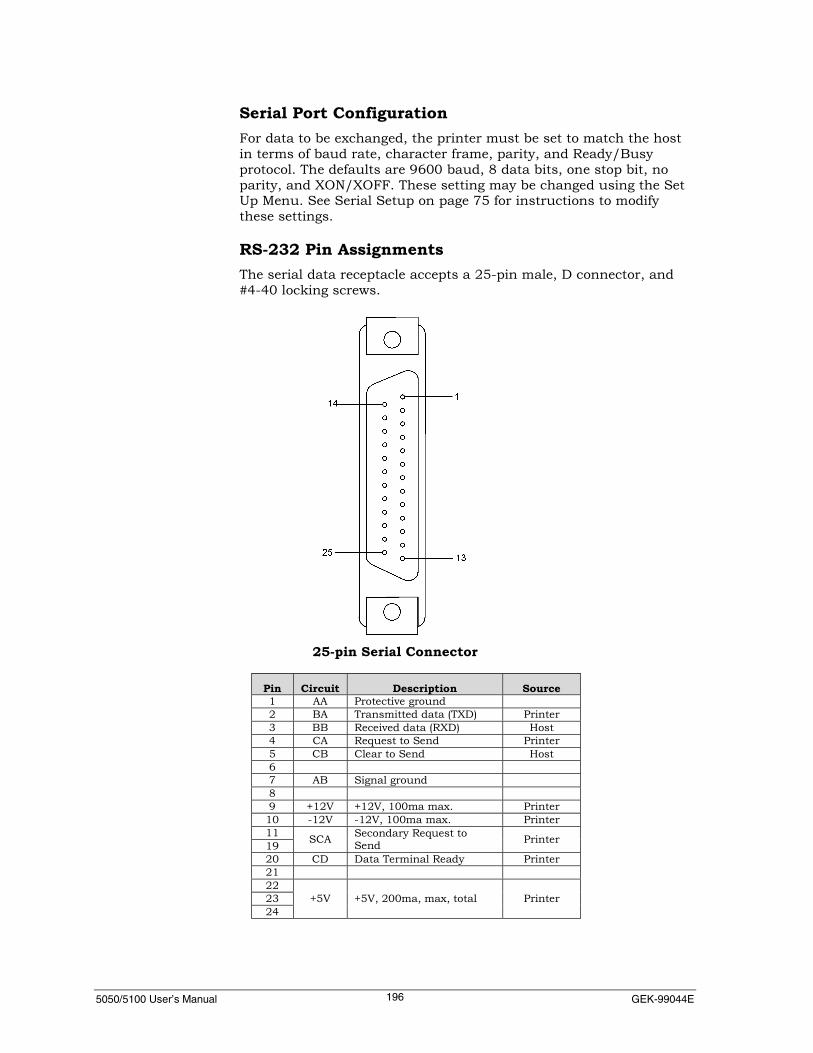
5050/5100 User’s Manual GEK-99044E196
Serial Port ConfigurationFor data to be exchanged, the printer must be set to match the hostin terms of baud rate, character frame, parity, and Ready/Busyprotocol. The defaults are 9600 baud, 8 data bits, one stop bit, noparity, and XON/XOFF. These setting may be changed using the SetUp Menu. See Serial Setup on page 75 for instructions to modifythese settings.
RS-232 Pin AssignmentsThe serial data receptacle accepts a 25-pin male, D connector, and#4-40 locking screws.
Pin Circuit Description Source1 AA Protective ground2 BA Transmitted data (TXD) Printer3 BB Received data (RXD) Host4 CA Request to Send Printer5 CB Clear to Send Host67 AB Signal ground89 +12V +12V, 100ma max. Printer10 -12V -12V, 100ma max. Printer1119 SCA Secondary Request to
Send Printer
20 CD Data Terminal Ready Printer21222324
+5V +5V, 200ma, max, total Printer
25-pin Serial Connector

5050/5100 User’s Manual Appendix H. Interface, Emulation and Filter Information197
RS-422 InterfaceThis interface is a four-wire, balanced-voltage variant of RS-232. Inorder to use this interface. To use this interface, it must be selectedfrom the Serial Type menu. The character frame, baud rate, andprotocol settings are accessible from the same Serial Setup menu asthe RS-232. See page 75 for instructions to modify these settings.TheReady/Busy protocol must be busy-by-code, usually XON/XOFF,which is enabled in the default state of the printer.
RS-422 Pin AssignmentThe RS-422 interface shares the 25-pin, D connector with the RS-232interface.
Pin Circuit Description Source1 Frame Ground (Not normally used)
15 RX-A Received Data Host
17 RX-B Received Data Host
19 TX-A Transmitted Data Printer
25 TX-B Transmitted Data PrinterThe polarity indicators A and B, are defined by the EIA specification.A is negative with respect to B in the mark (logic 1) state of thedevice.
25-pin SerialConnector

5050/5100 User’s Manual GEK-99044E198
Troubleshooting the RS-422For the RS-422 interface to perform, the interface must be selectedfrom the Serial Type Menu located under the Set Up menu. The baudrate, character frame, and Ready/Busy protocol (usually XON/XOFF)at the printer must match those of the host.
Host Printer Printer PinTX-A RX-A 15TX-B RX-B 17RX-A TX-A 19RX-B TX-B 25
Lead PolaritiesThe polarity indicators, -A and -B, are defined by the EIAspecifications. -A is negative with respect to -B in the mark (logic 1)state.
Some vendors designate RS-422 polarities with a plus or minus signrather than -A and -B without a consensis to their meanings. Ifpolarities are reversed, then (readable) data will not be exchanged;however, no damage will result.

5050/5100 User’s Manual Appendix H. Interface, Emulation and Filter Information199
Troubleshooting the RS-422 InterfaceProblem Probable Cause/Recommended ActionDetermine the Host’s TransmitPolicy
The host can be expected to hold a mark state on a quiescenttransmitter.Disconnect the outgoing wiring from the host’s TX terminals.Temporarily connect a one-hundred-ohm resistor across the TXterminals, and use an oscilloscope to measure the voltageacross the resistor. If there is a clean DC level of one to threevolts, then the negative transmit terminal is the -A terminal.Using this method to discern the meaning of the host’stransmitted polarity markings, then its received – sidemarkings should be the same sense and connect accordingly.The printer should be online and should now be ready to printdata from the host.
Host Times Out, or Does NotTransmit
If the host times out when data is sent, then the host is waitingfor XON.Verify from the printer’s Serial Setup menu that XON/XOFFreflects online/offline (default). Place the printer online. XONwill be transmitted. Attempt to send the file again.If the host times out again, change the XON/XOFF protocol toenable Robust XON. This will cause XON to be transmitted in 3second intervals while the printer is online and the buffer isavailable. Check the host’s receive terminals with anoscilloscope. Begin with a 1V/division, 500microseconds/division (at 9600 baud). There should be a clean,repetitive XON signals at better than 2V peak-peak. (Thespecified minimum is 200 millivolts at the receive terminals;the printer supplies close to 5V pk-pk.) If this signal is present,try to transmit the file again.At 9600 baud, the host will transmit about 58K of data perminute. For a 56K file, there will be a minute to look for dataon the transmit terminals.Check the host’s transmit terminals for data. There should be a2-6V pk-pk reading. If no data is present, then reverse theleads on the host’s receive terminals and check for data again.If there are XON’s at the host’s receive terminals, if baud ratesand character frames match, and both juxtapositions ofpolarities of the host’s receive terminals have been tried, andthe host still won’t transmit, the problem is with the host.
Host Transmits, but Data Check the printer’s receive terminals (pin 15 to 17) for data.There should be 200 millivolts peak-to-peak minimum.Typically, the amplitude will be closer to two volts andshouldn’t exceed six volts.If data is present, but the printer doesn’t print or printsgarbage, try reversing either the host’s transmit leads, or theprinter’s receive leads.
Verify XON/XOFF With the speed of the print engine relative to the speed of theserial interface, sometimes the printer correctly prints aquantity of high-speed text, open-loop, without indicating thatthe hand-shaking is not working properly. Once reception ofdata at the printer is established, checking the host’sprocessing of XON/XOFF can be checked. Verify that theXON/OFF protocol is set to reflect online/offline (default). Cyclethe online/offline while data is being transmitted and verifythat the host starts and stops transmitting in response to thekey. Using a scope, monitor incoming data using an autotrigger mode.

5050/5100 User’s Manual GEK-99044E200
PRINTER EMULATIONS AND FILTERSPrinter Emulation
Valid Filter SelectionsFilter
PrinterEmulation QMS IGP SCS IPDS
HexPrint
HexPass
ANSI (4800) X X X X X XANSI (4410) X X X XFX286e X X X XProprinter IIIXL X X X XP300/600 X X X XDec LG+ X XPseries X XDEC PPL/3 X X
Note 1: Only one printer emulation can be active.Note 2: If SCS and IPDS Filter are selected on any port (Expansion 1 or 2), ANSI (4800) printeremulation is automatically selected.Note 4: QMS and IGP are mutually exclusive.Note 5: SCS and IPDS are mutually exclusive.

5050/5100 User’s Manual Appendix H. Interface, Emulation and Filter Information201
PRINTER EMULATIONS AND TAB ID SLOTSHorizontal/Vertical Tab Id
Maximum SlotsMaximum Tab Id
SlotsPrinterEmulation Horizontal VerticalANSI (4800) 22 12ANSI (4410) 22 12FX286e 32 32Proprinter IIIXL 32 32P300/600 32 32Dec LG+ 32 67Pseries 32 32DEC PPL/3 32 64

5050/5100 User’s Manual GEK-99044E202
FILTER COMBINATIONS
Valid Filter Combinations
QMS IGP SCS IPDS HexPrint
HexPass
QMS X X XIGP X X XSCS X X X XIPDS X XHex Print X X X X XHex Pass X X X X X
Interface Port and Filter CompatibilityFilter
I/F Port QMS IGP SCS IPDS Hex Print
RS 232/422Serial X X X
1283 Parallel X X X
Ethernet 10Bt/10B2 X X (future) X
Ethernet10/100 base T X X (future) X
Token Ring X X (future) X
IBM TX/CX X X X X X
LegacyCENTRONICS X X X
Legacy DPLL X X X
Legacy DPSL X X X

5050/5100 User’s Manual Appendix I. LCD Menu Maps203
APPENDIX I. LCD MENU MAPS
Main Menu
Operator Menu Setup MenuMaintenance Menu Menu Control *1
Main Menu
Menu Contro l *1
Al low Menus
Operator< Setup< Maintenance<
Allow Keys
Tear Off View Format
NoteOperator, Maintenance, and Setup menus are expanded onseparate pages.
NoteTo display this menu, see “Using Menu Control” in Chapter 3 forinstructions.
*1 This menu is visible after menu control power-up procedures. See Menu Control in Chapter 3 for details.
NOTE
The following menu maps reflect the following software:Standard 44A109042IPDS 44A109037SCS 44A109036

5050/5100 User’s Manual GEK-99044E204
Operator
Main Menu
New Ribbon *2
*2 Not act ive i f Ribbon Moni tor is d isabled
Ribbon ResetReset (No)
Show
Sof twareIDs
StatusPage
Press Clr to Stop
Formats
Test Pat tern Discard Job
Press Clr to Stop
CodePage
FontPage
Ribbon ResetReset (Yes)
Ribbon ResetRest to 0 X X M
Ribbon ResetCurrent ly 0 X X M

GEK-99044E Appendix I. LCD Menu Maps205
Format
Modify Format
SaveFormat
Form Length
Format Name
10<1213.31516.717.120XX.X User Set
346<8XX UserSet
By Lines(6 LPI)
0 66
LeftMargin
RightMargin
Left PrintRef
By Column
By IN
00.00
HorizExpansion
VertExpansion
Ver tExpOpt ions
SlewRate
By IN
Defaul t Code Page Country
By ColumnBy IN
DEFAULTBlank Format 1
...B lank Format 9
Data Proces<High SpeedCorrespondGoth ic NLQCour ier NLQItal ic NLQOCR-AOCR-BCanadianPstGraphicsHigh Speed 2
FontStyle
USA ISO<Germany ISOFrench A ISOFrench B ISOCanadianDutchItalianUK ISOSpanishDan/Nor ADan/Nor BDan/Nor CDan/Nor DSwed/F in ASwed/F in BSwed/F in CSwed/F in DSwissSlo/CroatUK ATurkishGreekItal ian ISOSpanish ISOGreek 2Greek 3Greek 4Greek 5IRAN ISOFX: USAFX: FranceFX: GermanyFX: UKFX: Denmark IFX: SwedenFX: ItalyFX: Spain IFX: JapanFX: NorwayFX: Denmark I IFX: Spain I IFX: Lat in AmerFX: Nether landFX: Angl-UnvrslFX: Span AmerFX: PortugalFX: Afr icaFX: Switzer landFX: TurkeyFX: GreeceFX: Slo/CroatLegalKoreaNone
By Lines (8 LPI)
Right Margin INRight Margin
Col
Top Pr int Ref IN
Lft Print Ref IN Left Ref Col
Top Pr intRef
Default ( top)<Basel ine
DoubleStr ikeEmphas ized
PrintModif iers
High Speed<UpperCase
PrintOpt ions
X1<.
X8
X1<.
X8
Normal<Reduced
Def ine LF
LF = LFLF = CR + LF<
Def ine CR
CR = CR<CR = CR + LF
Def ine FF
FF = FFFF = CR + FF<
NoTabs = SPACE<NoTabs = Ignore
Ver tMove
VM = VMVM = CR +VM<
AutoWrap
Enable<Disable
FF @ TOF
Enable<Disable
Group 1 Group 2
0102<03<-08<-12<-32
01-04<-07<08<-11<12<13<-32
00.00<(1 3.60)
000<(136)
USA CP 437< Dec Nor /DanMul t i CP 850 Dec SpanishCode Page 852 Dec SwedishCode Page 853 Dec ISO Nor /DanCode Page 855 Dec DutchCode Page 858 Dec SwissCode Page 860 Dec Por tugueseCode Page 863 Dec LegalCode Page 864 Dec HebrewCode Page 865 Dec Hebrew SuppCode Page 866 Dec ISO Lat /HebCode Page 867 Dec KatakanaIGreek CP 437 Dec ANSIDec Mult iNtnl ISO Lat in 2Roman 8 ISO Lat in 5Mazowia CP Greek SuppTurk ish CP Turkish 7-BitGreek CP 851 Turkish 8-BitK a m e n ISO Lat /Gr SuppISO-8859-1 ISO Lat /Cy SuppISO-8859-2 PC 437 GreekISO-8859-3 PC 861 IcelandicISO-8859-4 PC 869 GreekISO-8859-5 USSR (GOST)ISO-8859-6 BRASCIIISO-8859-7 AB ICOMPISO-8859-8 PC 857 (Turk ish)ISO-8859-9 ISO Lat in 1TISO-8859-15 Bulgar iaCode Page 864E Code MJK (CSFR)Greek CP 869 EstoniaELOT 928 Li thuania PC774Dec Supp PC 866 LATDec Tech ECMA-94-1 Mul tDec Spec1Graph KU 42 (KU Thai)Dec ISO-Lat in 1 TIS 11 (TS 988)Dec Br i t ish TIS 13 ( IBM Std)Dec Finnish TIS 16 (SIC Old)Dec French TIS 17 (SIC STD)Dec FrCanadian TIS 18 General )Dec German HP3000 GreekDec ISO I tal ian FARSI ADec J IS Roman FARSI B
FARSI CNoneRevQues t
088
By ColumnBy IN
Left Margin IN Left MarginCol
00.00(13.20)
000(132)
Setup
Main Menu
Code Pg/Country CPI LPI PrintControl
GenPt rOpts
0.00< 0.00<
Top Level Menu Options Continued on Next Page
Def ine HT

5050/5100 User’s Manual GEK-99044E206
Mul t iSource<Ser ia lPara l le l (1284)Expans ion 1Expans ion 2
Setup
Main Menu
SelectI/F
I/FSet t ings
Mul t iSource Para l le l Setup Ser ia l
Ser ia lT y p e
Ser ia l Setup
R S 2 3 2 <R S 4 2 2
X O N / X O F F * 4
Ready /Busy<ON/OFF l i ne<Fau l t<R o b u s t X O F FR o b u s t X O N
CD (DTR) CA (RTS) SCA (SRTS) E T X / A C K
Disab le<Immed ia teOn Prn Comp le teF low Cont ro l led
Neve r<V ia CB(CTS)
CD (DTR) CA (RTS) SCA (SRTS) CB (CTS) CC (DSR)
7 B ITS8 B ITS<
No Par i ty B i t<IgnoreE v e nO d dS p a c eMark
1 <2
1 2 0 02 4 0 04 8 0 09 6 0 0 <1 9 2 0 03 8 4 0 0
Expans ion 1 Expans ion 2
Legacy Para l le l
Token R ing T C P I P Ne tware
I /F Type
Cent ron ics< DP (Shor t ) DP (Long)
H bi ts01 -32
H bi ts33 -64
0 1-0 3 <0 4 <-0 8 <-1 1 <1 2 <1 3 <1 4 <1 5 <1 6 <-2 5 <2 6 <2 7 <-3 0 <3 1 <3 2
3 3 <3 4 <3 5 <3 6 <3 7 <-6 4
I /F Straps
Bi ts 01-32 Bi ts 33-64
0 1-0 4 <-0 8 <-3 2
3 3-6 4
16 MBi t Speed<4 MBi t Speed
IP Address N e t m a s k Router IP Addr F rame Type
Ethernet 2802 .3<
0 10 .001 .001 .001
255 .255 .255 .000
0 00 .000 .000 .000
Frame Type
802 .3<802 .2Ethernet 2S N A P
De lay Seconds
No Fau l t PO & OFFTCP/ IP
8 0 <
Expansion 1 & 2
0 0 3
Coax *6 Twinax *5
Emula t ion
4 2 2 43 2 8 74 2 3 4 <3 2 6 23 2 6 84 2 1 4
Buf fer S ize
9 6 01 9 2 02 5 6 03 4 4 03 5 6 4
Ear ly Comp le te
Disab leEnab le
Emula t ion
4 2 3 44 2 4 55 2 5 65 2 6 24 2 1 45 2 2 45 2 2 5
Sta t ion Addr
0123456
Buf fer S ize
2 5 61 0 2 4
I/FSt raps
*4 Only opt ion avai lab le for RS422*5 SCS/ IPDS sof tware and TX/CX opt iona l board must beinstal led*6 Only v is ib le wi th SCS & IPDS sof tware insta l led
NoteA dotted line indicates optional hardware/software installation required to view menuitems.
Ready /BusyON/OFF l i neFaul t
Ready /BusyON/OFF l i neFaul t
Ready /BusyON/OFF l i neFaul t
H igh<L o w
H bi ts01 -32
H bi ts33 -64
0 1-0 3 <0 4 <-0 8 <-1 1 <1 2 <1 3 <1 4 <1 5 <1 6 <1 7 <-2 1 <2 2 <-2 5 <-2 7 <-2 9 <3 0 <3 1 <3 2
I/FSt raps
IBM HostSta tus *5
Enab le<Disab le
3 3 <-6 4
Da taBi ts
L e a dPolar i ty
Inhibi tXmi t
Pro toco l Par i tyS topBi ts
B a u dRa te
High Tr ipP t %
Top Level Menu Options Continued from Previous Page Top Level Menu Options Continued on Next Page
NoteEmulation does not appear in IPDS Twinaxsoftware.
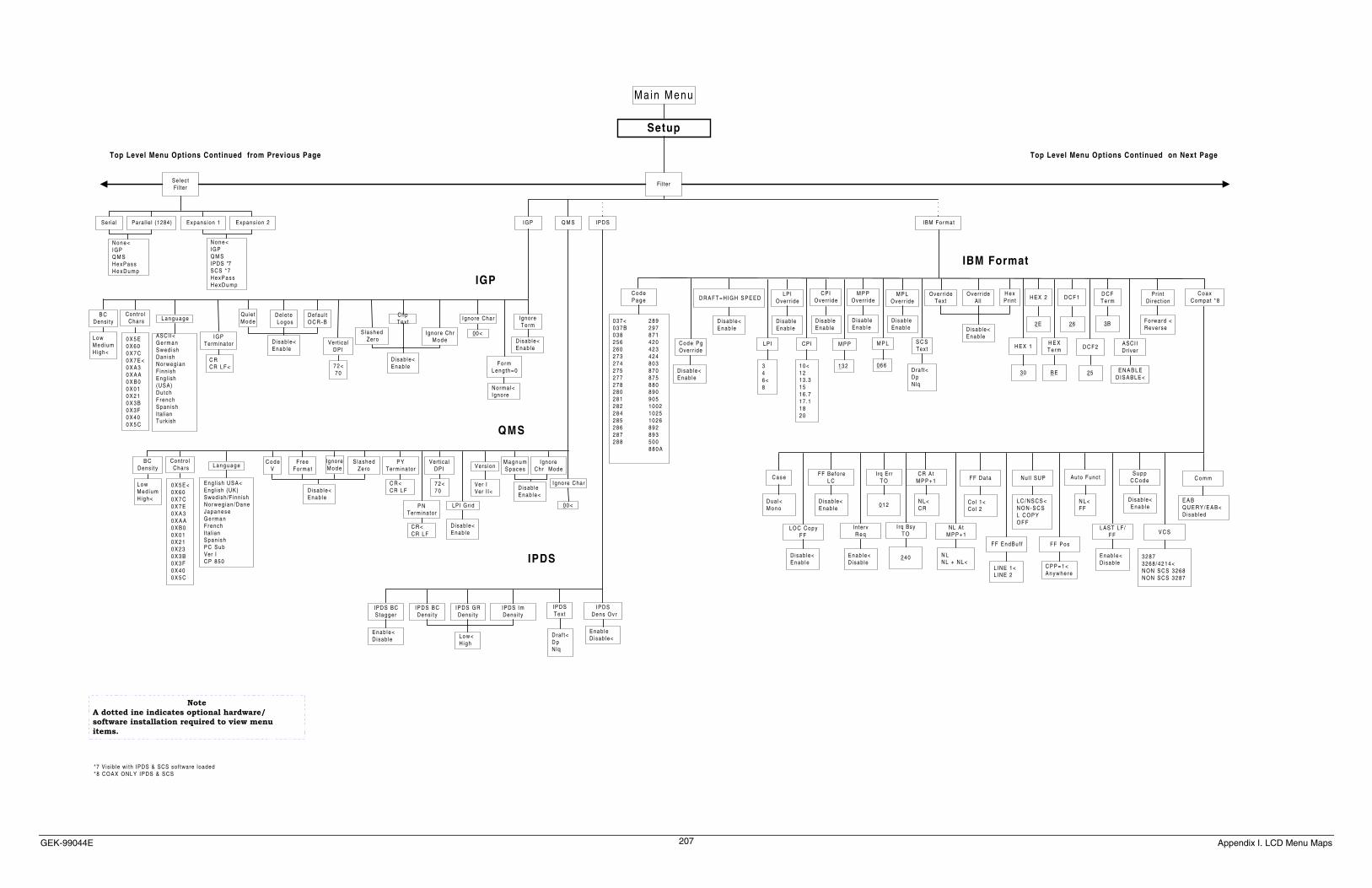
GEK-99044E Appendix I. LCD Menu Maps207
Selec tFi l ter
Fi l ter
Ser ia l Para l le l (1284) Expans ion 2Expans ion 1
N o n e <IGPQ M SH e x P a s sH e x D u m p
N o n e <IGPQ M SIPDS *7SCS *7H e x P a s sH e x D u m p
*7 V is ib le w i th IPDS & SCS sof tware loaded* 8 C O A X O N L Y I P D S & S C S
L o wM e d i u mHigh<
0 X 5 E0 X 6 00 X 7 C0 X 7 E <0 X A 30 X A A0 X B 00 X 0 10 X 2 10 X 3 B0 X 3 F0 X 4 00 X 5 C
ASCI I<G e r m a nSwed i shDan ishNorweg ianFinn ishEng l ish(USA)Du tchFrenchSpan ishItal ianTurk ish
IGPTerminator
C RC R L F <
Dele te Logos
Defau l tO C R - B
7 2 <7 0
Cl ipTex t
Ignore ChrM o d e
Ignore Char
L o wM e d i u mHigh<
0 X 5 E <0 X 6 00 X 7 C0 X 7 E0 X A 30 X A A0 X B 00 X 0 10 X 2 10 X 2 30 X 3 B0 X 3 F0 X 4 00 X 5 C
Eng l i sh USA<Engl ish (UK)Swed ish /F inn ishNorweg ian /DaneJ a p a n e s eG e r m a nFrenchItal ianSpan ishP C S u bVer IC P 8 5 0
C o d eV
FreeFormat
IgnoreM o d e
P YTerminator
P NTerminator
7 2 <7 0
M a g n u mS p a c e s
IgnoreChr Mode
00 <
IGP
QMS
IPDS BCStagger
I P D S Dens Ovr
IPDS BCDens i ty
I P D S G RDens i ty
IPDS ImDens i ty
Enab le<Disab le L o w <
High
Enab leDisab le<
IPDS
C o d eP a g e
C o d e P gOver r ide
LPIOver r ide
M P POver r ide
M P LOver r ide
Over r ideAll
H E X 1
H E X 2
H E XT e r m
C o a xCompa t *8
0 3 7 < 2 8 90 3 7 B 2 9 70 3 8 8 7 12 5 6 4 2 02 6 0 4 2 32 7 3 4 2 42 7 4 8 0 32 7 5 8 7 02 7 7 8 7 52 7 8 8 8 02 8 0 8 9 02 8 1 9 0 52 8 2 1 0 0 22 8 4 1 0 2 52 8 5 1 0 2 62 8 6 8 9 22 8 7 8 9 32 8 8 5 0 0
8 8 0 A
Disab le<Enab le
Disab leEnab le
Disab leEnab le
Disab leEnab le Disab le<
Enab le
C a s e
L O C C o p yF F
FF Be fo reL C
IntervR e q
Irq ErrT O
Irq BsyT O
CR A tM P P + 1
NL A tM P P + 1
FF Da ta
FF EndBu f f
Nu l l SUP
FF Pos
Auto Func t
LAST LF /F F
S u p pC C o d e
V C S
C o m m
E A BQ U E R Y / E A B <Disab led
3 2 8 73 2 6 8 / 4 2 1 4 <N O N S C S 3 2 6 8N O N S C S 3 2 8 7
Disab le<Enab le
Enab le<Disab le
N L <F F
C P P = 1 <A n y w h e r e
L C / N S C S <N O N - S C SL C O P YO F F
LINE 1<L INE 2
Co l 1<Col 2
N LNL + NL<
N L <C R
24 0
01 2
Enab le<Disab le
Disab le<Enab le
Disab le<Enab le
Dua l<M o n o
IBM Format
00 <
CPIOver r ide
Disab leEnab le
Over r ideTex t
H e xPrint D C F 1
D C F 2
D C FT e r m
Setup
Main Menu
NoteA dotted ine indicates optional hardware/software installation required to view menuitems.
Contro l Chars
B CDens i ty
D isab le<Enab le
Vert icalDPI
S lashed Zero
Disab le<Enab le
Cont ro l Chars
B CDens i ty
D isab le<Enab le
S lashedZero
Vert icalDPI Vers ion
LPI Gr id
D isab le<Enab le
Disab leEnab le<
Ver IVer I I<
C R <C R L F
C R <C R L F
Ignore Char
LPI
346 <8
CPI
1 0 <1 213 .31 516 .717 .11 82 0
M P P
13 2
M P L
06 6
S C SText
Dra f t<D pNlq
30
2E
B E
26
25
3B
I P D SText
Dra f t<D pNlq
D R A F T = H I G H S P E E D
Disab le<Enab le
IgnoreT e r m
Disab le<Enab le
F o r mLeng th=0
Norma l<Ignore
IGP Q M S I P D S IBM Format
Top Level Menu Options Continued from Previous Page Top Level Menu Options Continued on Next Page
Quie tM o d eL a n g u a g e
L a n g u a g e
ASCI IDr iver
E N A B L ED I S A B L E <
PrintDi rect ion
Forward <Reve rse
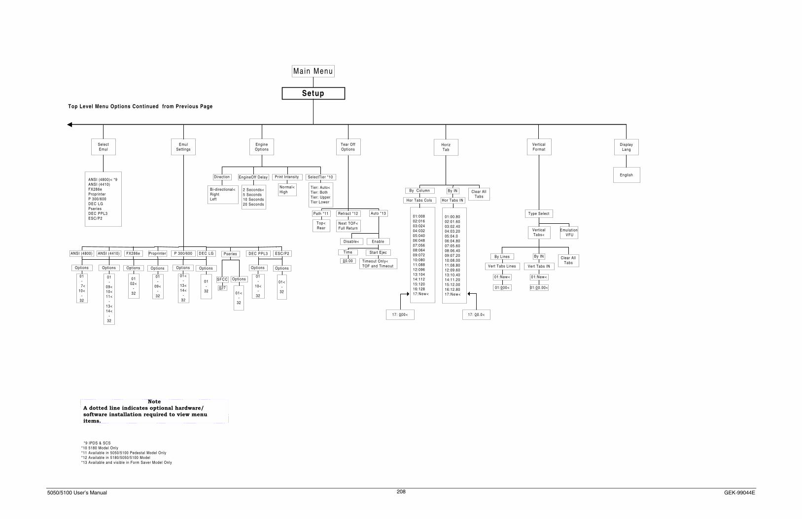
5050/5100 User’s Manual GEK-99044E208
SelectEmul
EmulSettings
Setup
Main Menu
ANSI (4800)< *9ANSI (4410)FX286eProprinterP 300/600DEC LGPseriesDEC PPL3ESC/P2
*9 IPDS & SCS*10 5180 Model Only*11 Available in 5050/5100 Pedestal Model Only*12 Available in 5180/5050/5100 Model*13 Available and visible in Form Saver Model Only
ANSI (4800) ANSI (4410) FX286e Proprinter P 300/600 DEC LG Pseries
SFCC
DEC PPL3
Options
ESC/P2
01<-
32
Options
027
01-
10<-
32
Options
01-
7<10<
-32
Options
01-
09<10<11<
-13<14<
-32
Options
0102<
-32
Options
01-
09<-
32
Options
01<-
13<14<
-32
Options
01-
32
Options
EngineOptions
EngineOff Delay
2 Seconds<5 Seconds10 Seconds20 Seconds
Print Intensity
Normal<High
Direction
Bi-directional<RightLeft
SelectTier *10
Tier: Auto<Tier: BothTier: UpperTier Lower
Tear OffOptions
HorizTab
VerticalFormat
DisplayLang
Path *11 Retract *12 Auto *13
Next TOF<Full Return
Time Start Ejec
00.00 Timeout Only<TOF and Timeout
EnableDisable<
Top<Rear
01:00802:01603:02404:03205:04006:04807:05608:06409:07210:08011:08812:09613:10414:11215:12016:12817:New<
By IN
Hor Tabs IN
Clear AllTabs
Hor Tabs Cols
By Column
01:00.8002:01.6003:02.4004:03.2005:04.006:04.8007:05.6008:06.4009:07.2010:08.0011:08.8012:09.6013:10.4014:11.2015:12.0016:12.8017:New<
Emulation VFU
01:New<
By IN
01:New<
Type Select
VerticalTabs<
Clear AllTabs
By Lines
English
Top Level Menu Options Continued from Previous Page
NoteA dotted line indicates optional hardware/software installation required to view menuitems.
01<-
32
Vert Tabs Lines
17: 000< 17: 00.0<
01:000< 01:00.00<
Vert Tabs IN

GEK-99044E Appendix I. LCD Menu Maps209
Reset toDef l ts
A l ignment
Pat tern
Signature Ampl i tude Inter GapChecker
BoardHorz T ime Vert T ime
Pattern
Adjust Ampl i tude
RibbonMoni to r
Disable< EOL L imi t
060<
E O LWarn ing
10<
Dot CountsPrintChar t
Actuator Status
00:000000000 *14
Actuators Fai led*16
Power On T ime Print T ime
H H H H H - M M - S SU S AInternat iona
l
Clr to Stop
Enab le<
Clr to Stop
Save Ampl i tude
Clr to Stop
Maintenance
Main Menu
Total InitAl l FormatsAl l Emulat ionsAl l Interfaces
Tier 1:XX *15
T1:01:000000000 *15
*14 Information wi l l ref lect the actuator number (1-33) fol lowed by the dot count value for each actuator (1-33).*15 5180 model only. Information wi l l ref lect Tier 1(2) and actuators 1-33(34-66)*16 Either "None" or a # wi l l be displayed to ref lect which actuator has fai led
HeadServ ice
Select to Reset
NoteA dotted line indicates optional hardware/softwareinstallation required to view menu items.
Upgrade Status:Ready
UpgradeFlash
OnboardFlash
S I M MFlash

5050/5100 User’s Manual GEK-99044E210
Index2
25-pin RS-232C serial interface connector ............4
3
36-pin CENTRONICS parallel interface connector.........................................................................4
A
Active Format ......................................................32Actuator Status...................................................147AdjustAmplitude................................................143Alignment ..........................................................141ANSI (4410) ......................................................127ANSI (4410) Emulation Options Table .............189ANSI (4800) ......................................................127ANSI (4800) Emulation Options Table .............189ANSI 4410 .............................................................1ANSI 4800 .............................................................1Appendix A. Unpacking Instructions.................167Appendix B. Paper Specifications......................173Appendix C. Considerations for Operation.......175Appendix D. Parts, Accessories, Consumables, and
Options ........................................................177Appendix E. Font Print Samples........................178Appendix G Description of Strapping Options ..183Appendix H. Interface Emulation Compatibility193Appendix I. LCD Menu Maps ...........................203Auto ...................................................................135Auto Funct .........................................................123auto-switching power supply .................................4AutoWrap.............................................................68
B
Bad Actuator.... Also See Mechanical Problems, Hard Faults
Bad Wire Driver..............................See Hard FaultsBasic Pushbutton Use.............................................8Baud Rate.............................................................81BC Density.....................................................93, 99Beeper ....................................................................7Buffer Overflow.............See Serial Interface Errors
C
CA(RTS)..............................................................77Case....................................................................118CD(DTR) .............................................................76Centronics ............................................................84CENTRONICS ......................................................1Change Ribbon.................................See Soft FaultsCHAPTER 1. Introduction.....................................1CHAPTER 2. Getting Started ................................3
CHAPTER 3. Operating the Printer .................... 30Chapter 4. Using the Operator Menu................... 42Chapter 5. Using the Set Up Menu...................... 51Chapter 6. Using the Maintenance Menu .......... 139Chapter 7. Operator Care and Maintenance....... 149Character Set ....................................................... 54CharSet/Country .................................................. 53Clip Text.............................................................. 97Coax..................................................................... 86Coax Compatibility............................................ 118Code Page.......................................................... 108Code Pg Override .............................................. 108Code V............................................................... 101column indicator label ......................................... 20Comm ................................................................ 125Connecting the Interface Cable ............................. 4Connecting the Power Cord................................... 4Considerations for Operation............................. 175Control Chars............................................... 94, 100Control Panel Initialization.................................. 40Country................................................................ 54Courier NLQ.......................................................... 1CPI55, 109CPI Override...................................................... 110CR at MPP+1..................................................... 121
D
Data Bits .............................................................. 79Data Entry.............................................................. 9DCF Term.......................................................... 117DCF1 ................................................................. 115DCF2 ................................................................. 116DEC LG............................................................. 129DEC LG and PPL3 ................................................ 1DEC LG Plus Emulation Options Table............ 192DEC PPL3 ......................................................... 130DEC PPL3 Emulation Options Table ................ 192Default OCR-B.................................................... 96Define CR............................................................ 66Define FF............................................................. 67Define HT............................................................ 67Define LF............................................................. 66Delete Logos........................................................ 95Description of the Control Panel ........................... 6Direction............................................................ 131Discard Job .......................................................... 50Display................................................................... 7Display Lan ....................................................... 138Dot Counts......................................................... 146DP(Long)............................................................. 85DP(Short)............................................................. 84Draft = High Speed............................................ 108Driver Circuit..................................................... 159

5050/5100 User’s Manual Index211
Also See Mechanical Problems, Hard Faults
E
Electrical Problems ............................................158Emulation...................................................126, 127Emulation Option descriptions...........................189Emulation VFU..................................................138Engine Options ..................................................131EngineOff Delay ................................................131Epson FX286e .......................................................1Epson FX286e Emulation Options Table ..........191ETX/ACK ............................................................78Euro information..................................................69Euro Information................................................185Expansion1/Expansion2.......................................83
F
paper ..................................................................173features of this printer ............................................1FF @ TOF............................................................68FF Before LC.....................................................119FF Data ..............................................................122FF EndBuff ........................................................122FF Pos ................................................................123Figure A-5 Brackets & Screws ..........................170Filter...............................................................91, 93Filter Combinations ...........................................202Font Style.............................................................53Form Length ..................................................33, 56Format..................................................................51Format Name .......................................................52Framing Error ................See Serial Interface ErrorsFree Format........................................................101FX286E..............................................................128
G
General Printer Options Definitions ..................184GenPtrOpts ..........................................................69Gothic NLQ ...........................................................1Graphics.................................................................1
H
Hard Faults.........................................................156Bad Actuator................................................157Bad Wire Driver ..........................................157Driver Circuit...............................................157Image Logic Fail..........................................157Left Center Fan............................................157Left Fan .......................................................157Low Power ..................................................157No Font........................................................157NVRAM Reinit ...........................................157Rear Fan ......................................................157Right Center Fan..........................................157Right Fan .....................................................157Shuttle Overload..........................................157
VFU Fmt Inactive ....................................... 157HeadService....................................................... 146Hex 1 ................................................................. 114Hex 2 ................................................................. 115Hex Print ........................................................... 113Hex Term........................................................... 115High Speed ............................................................ 1High Trip Pt% ..................................................... 82Horiz Expansion .................................................. 61Horiz Tab........................................................... 136Horizontal Positioning of the Paper..................... 20Horizontal/Vertical Tab Id Maximum Slots ...... 201
I
I/F Hardware Strap Table .................................. 187I/F Software Straps Table.................................. 188I/F Straps ............................................................. 85IBM Format....................................................... 107IBM Proprinter III XL........................................... 1Ignore Char.................................................. 98, 105Ignore Chr mode.......................................... 97, 104Ignore Mode ...................................................... 101IGP ...................................................................... 93IGP Terminator.................................................... 95Image Logic Fail ................... See Image Logic FailInhibit Xmit ......................................................... 78Initializing the Printer.................................. 38, 150Installing the Paper Handling System
(55 OR 60 DBA) CABINET MODELS........ 10Interface............................................................... 71Interface Port and Filter Compatibility.............. 202Interface Settings ................................................. 71Interv Req .......................................................... 119Invalid VFU Seq.............................. See Soft FaultsIPDS .................................................................. 105IPDS BC Density............................................... 106IPDS BC Stagger............................................... 105IPDS Dens Ovr.................................................. 107IPDS GR Density .............................................. 106IPDS Image Density .......................................... 106IPDS Text .......................................................... 107Irq Bsy TO......................................................... 120Irq Err TO.......................................................... 120Italic NLQ.............................................................. 1
L
Language ..................................................... 94, 100LAST LF/FF...................................................... 124Lead Polarity ....................................................... 79Left Center Fan............................... See Hard FaultsLeft Fan .......................................... See Hard FaultsLeft Margin.......................................................... 57Left Print Ref....................................................... 60Legacy Parallel .................................................... 83Legacy parallel Hardware strap definitions ....... 186Legacy Parallel Software Strap Definitions ...... 188
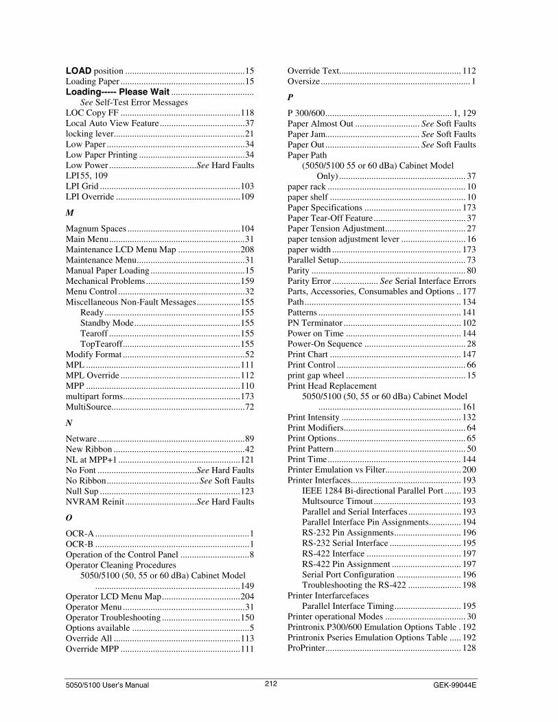
5050/5100 User’s Manual GEK-99044E212
LOAD position ....................................................15Loading Paper ......................................................15Loading----- Please Wait ....................................
See Self-Test Error MessagesLOC Copy FF ....................................................118Local Auto View Feature.....................................37locking lever.........................................................21Low Paper ............................................................34Low Paper Printing ..............................................34Low Power ......................................See Hard FaultsLPI55, 109LPI Grid .............................................................103LPI Override ......................................................109
M
Magnum Spaces .................................................104Main Menu...........................................................31Maintenance LCD Menu Map ...........................208Maintenance Menu...............................................31Manual Paper Loading .........................................15Mechanical Problems.........................................159Menu Control .......................................................32Miscellaneous Non-Fault Messages...................155
Ready...........................................................155Standby Mode..............................................155Tearoff .........................................................155TopTearoff...................................................155
Modify Format .....................................................52MPL ...................................................................111MPL Override ....................................................112MPP ...................................................................110multipart forms...................................................173MultiSource..........................................................72
N
Netware................................................................89New Ribbon .........................................................42NL at MPP+1 .....................................................121No Font ...........................................See Hard FaultsNo Ribbon........................................See Soft FaultsNull Sup .............................................................123NVRAM Reinit ...............................See Hard Faults
O
OCR-A...................................................................1OCR-B ...................................................................1Operation of the Control Panel ..............................8Operator Cleaning Procedures
5050/5100 (50, 55 or 60 dBa) Cabinet Model...............................................................149
Operator LCD Menu Map..................................204Operator Menu .....................................................31Operator Troubleshooting ..................................150Options available ...................................................5Override All .......................................................113Override MPP ....................................................111
Override Text..................................................... 112Oversize................................................................. 1
P
P 300/600....................................................... 1, 129Paper Almost Out ............................ See Soft FaultsPaper Jam......................................... See Soft FaultsPaper Out......................................... See Soft FaultsPaper Path
(5050/5100 55 or 60 dBa) Cabinet ModelOnly) ....................................................... 37
paper rack ............................................................ 10paper shelf ........................................................... 10Paper Specifications .......................................... 173Paper Tear-Off Feature........................................ 37Paper Tension Adjustment................................... 27paper tension adjustment lever ............................ 16paper width ........................................................ 173Parallel Setup....................................................... 73Parity ................................................................... 80Parity Error .................... See Serial Interface ErrorsParts, Accessories, Consumables and Options .. 177Path.................................................................... 134Patterns .............................................................. 141PN Terminator ................................................... 102Power on Time .................................................. 144Power-On Sequence ............................................ 28Print Chart ......................................................... 147Print Control ........................................................ 66print gap wheel .................................................... 15Print Head Replacement
5050/5100 (50, 55 or 60 dBa) Cabinet Model.............................................................. 161
Print Intensity .................................................... 132Print Modifiers..................................................... 64Print Options........................................................ 65Print Pattern ......................................................... 50Print Time.......................................................... 144Printer Emulation vs Filter................................. 200Printer Interfaces................................................ 193
IEEE 1284 Bi-directional Parallel Port ....... 193Multsource Timout...................................... 193Parallel and Serial Interfaces....................... 193Parallel Interface Pin Assignments.............. 194RS-232 Pin Assignments............................. 196RS-232 Serial Interface ............................... 195RS-422 Interface ......................................... 197RS-422 Pin Assignment .............................. 197Serial Port Configuration ............................ 196Troubleshooting the RS-422 ....................... 198
Printer InterfarcefacesParallel Interface Timing............................. 195
Printer operational Modes ................................... 30Printronix P300/600 Emulation Options Table . 192Printronix Pseries Emulation Options Table ..... 192ProPrinter........................................................... 128

5050/5100 User’s Manual Index213
Proprinter III XL Emulation Options Table.......190Protocol................................................................75Pseries ............................................................1, 130Pushbuttons............................................................7PY Terminator ...................................................102
Q
QMS.....................................................................99Quiet Mode ..........................................................95
R
Reading the Scale.................................................26Ready ........See Miscellaneous Non-Fault MessagesRear Fan..........................................See Hard FaultsRecommended Paper Weights ...........................173reinker ..................................................................22reinker lever .........................................................22re-install the paper guide......................................14Removing a Ribbon (50,55, or 60 dBa) Cabinet
Model ............................................................25Repacking ..........................................................172Replacement Procedure .....................................162Replenishing Paper Supply ..................................35Reset to Deflts....................................................140Resetting Print Head Counters...........................165Retract................................................................134Retracting.............................................................37ribbon cartridge....................................................21ribbon drive knob.................................................21Ribbon Jam...........................................................
See Soft Faults, Paper Tear-Off FeatureRibbon Removal and Installation
5050/5100 (50,55, or 60 dBa) Cabinet Model................................................................22
Ribbon Weld....................................See Soft FaultsRibbon Weld Pass............................See Soft FaultsRibbonMonitor...................................................145Right Center Fan.............................See Hard FaultsRight Fan ........................................See Hard FaultsRight Margin........................................................58RUN position.......................................................21
S
Sample Character Set...........................................48Sample Font Page ................................................48Sample Form Page ...............................................46Save Format .........................................................70SCA(SRTS) .........................................................77SCS Text ............................................................112See Low Paper"...................................................... .See Low Paperr ........................................................Selecting the Paper Path
5050/5100 (55 and 60 dBa) Cabinet ModelOnly.........................................................12
Self Test....................See Self-Test Error MessagesSelf-Test Error Messages...................................160
Loading ----- Please Wait............................ 160Self Test ...................................................... 160Shuttle Error................................................ 160TTMI checksum.......................................... 160TTMI error .................................................. 160TTMI noresp ............................................... 160
Semiautomatic Paper Loading............................. 19Serial.................................................................... 74Serial interface Errors........................................ 161Serial Setup.......................................................... 75Serial Type .......................................................... 74Service Time.................................... See Soft FaultsSetting the Print Gap ........................................... 26Setting top of form............................................... 36Setting up a FormAT........................................... 32Setting up an Active Format................................ 33Setup LCD Menu Map - (1 of 3) ....................... 205Setup LCD Menu Map (2 of 3) ......................... 206Setup LCD Menu Map (3 of 3) ......................... 207Setup Menu.......................................................... 31Show.................................................................... 42Shuttle Error.......... See Self-Test Error MessagesShuttle Overload............................. See Hard FaultsSlashed Zero ................................................ 96, 102Slew Rate............................................................. 69Soft Faults ......................................................... 152
Change Ribbon............................................ 153Invalid VFU Seq ......................................... 153No Ribbon................................................... 154Paper Almost Out........................................ 153Paper Jam.................................................... 153Paper Out .................................................... 153Ribbon Jam ................................................. 154Ribbon Weld ............................................... 154Ribbon Weld Pass ....................................... 154Service Time ............................................... 153Striker Bar Open ......................................... 154VFU Missing TOF ...................................... 153VFU PI Lead ............................................... 153VFU Tbl Too Long ..................................... 153
Software IDs........................................................ 43stacking aid.......................................................... 10Standby Mode..........................................................
See Miscellaneous Non-Fault MessagesStatus Display...................................................... 30Status Page .......................................................... 43Stop Bits .............................................................. 81Striker Bar Open.............................. See Soft FaultsStrikr Bar Open ........See Paper Tear-Off FeatureSupp CCode....................................................... 124
T
Table 3 Group 1 Options ................................... 184Table 4 Group 2 Options ................................... 185Table 7-1 Soft Fault Displays............................ 153Table 7-2 Miscellaneous Non-Fault Messages.. 155

5050/5100 User’s Manual GEK-99044E214
Table 7-3 Hard Fault Displays ...........................157TCP/IP .................................................................88Tearoff ......See Miscellaneous Non-Fault MessagesTearOff...............................................................133Test Pattern Printing.............................................28the horizontal paper adjustment knob ..................20The Interlock circuit.............................................38The Ribbon Cartridge
5050/5100 (50, 55 or 60 dBa) Cabinet Model.................................................................22
The Ribbon Deck5050/5100 (55 or 60 dBa) Cabinet Model .....21
Token Ring...........................................................86Top Print Ref..................................................33, 59TopTearoff ...............................................................
See Miscellaneous Non-Fault MessagesTTMI checksum.....See Self-Test Error MessagesTTMI error...............See Self-Test Error MessagesTTMI noresp...........See Self-Test Error MessagesTwinax .................................................................87
U
UART Overflow ................................................161Unpacking (5050/5100 55 DbA Model) ............170Unpacking (5180 52 DbA Model) .....................167Unpacking Instructions ......................................167Upgrade Flash ....................................................148
Using the Keypad to InitializeHow to Initialize the Printer .......................... 39
Using the menu control Menu ............................. 41
V
VCS ................................................................... 124Version .............................................................. 103Vert Expansion .................................................... 62VertExp Options .................................................. 63Vertical DPI................................................. 96, 103Vertical Format.................................................. 137Vertical Tabs ..................................................... 137VertMove............................................................. 67VFU Fmt Inactive...........................See Hard FaultsVFU Missing TOF........................... See Soft FaultsVFU PI Lead.................................... See Soft FaultsVFU Tbl Too Long.......................... See Soft FaultsViewing ............................................................... 37
W
When to Initialize ................................................ 38wickets................................................................. 10Wire Paper Guide ................................................ 13
X
XON/XOFF ......................................................... 76
Y
yellow spool knob................................................ 22


