O P E R A T I O N S M A N U A L Genie Controllerless System Genie/200 Copyright QED Environmental Systems / Clean Environment Equipment, Inc., Oct 2002 1133 Seventh Street Oakland, California 94607 (800) 537-1767 — North America Only (510) 891-0880 — Tele. (510) 444-6789 — Fax [email protected] — E-mail www.cee.com Document No. 600258-04 Clean Environment Equipment QED Environmental Systems PO Box 3726 Ann Arbor, Michigan 48106-3726 (800) 624-2026 — North America Only (734) 995-2547 — Tele. (734) 995-1170 — Fax [email protected] — E-mail www.qedenv.com
Transcript
OPERATIONS
MANUAL
Genie Controllerless System
Genie/200
Copyright QED Environmental Systems / Clean Environment Equipment, Inc., Oct 2002
1133 Seventh StreetOakland, California 94607
(800) 537-1767 — North America Only(510) 891-0880 — Tele.(510) 444-6789 — [email protected] — E-mailwww.cee.com
Document No. 600258-04
Clean Environment Equipment
QED Environmental Systems
PO Box 3726Ann Arbor, Michigan 48106-3726
(800) 624-2026 — North America Only(734) 995-2547 — Tele.(734) 995-1170 — [email protected] — E-mailwww.qedenv.com
The equipment in this manual is protected under U.S. and foreign patents issued and pending:
U.S. Patents:Selective Oil Skimmer (SOS) 4,497,370Specific Gravity Skimmer (SPG) 4,663,037AutoPump (AP) 5,004,405Specific Gravity Skimmer (SPG) Product Sensing 5,474,685Vacuum/Pressure Hydrocarbon Recovery System 4,761,225SPG PSR technology 5,474,685AP-2 5,641,272Genie System 5,704,772 Canada Patent:Specific Gravity Skimmer (SPG) 1,239,868
"AP" is a Registered Trademark of "Clean Environment Equipment""AutoPump" is a Registered Trademark of "Clean Environment Equipment""SOS" is a Registered Trademark of "Clean Environment Equipment""Genie" is a Registered Trademark of "Clean Environment Equipment""SPG" is a Registered Trademark of "Clean Environment Equipment"SamplEase is a Trademark of "Clean Environment Equipment"The Clean Environment Equipment logo is a Registered Trademark of "Clean Environment Equipment"Clean Environment Equipment is a Registered Trademark of "Clean Environment Equipment"
Contents
Page iRevision 4 – October, 2002
Genie Manual
Table of ContentsIntroduction _______________________________________________ 1
Service ...................................................................................... 1Regional Service Centers and a Corporate Service Support Team ........................ 2Over 50 Years of Service Experience ..................... 2The Service Process .................................................. 2Equipment Design ................................................... 3Service Literature and Videos ................................ 4Philosophy ................................................................ 4How to Contact CEE................................................ 5
Single Stage Filter/Regulator ............................................... 20
Tank Adapter .......................................................................... 21
Hoses and Fittings .................................................................. 22Hose Color Code Table ........................................... 22
Well Support System .............................................................. 23
Compressed Air Supply ........................................................ 37
Cold Weather .......................................................................... 37Actions To Take ........................................................ 37
Chapter 5: Start Up and Operation ___________________________ 53
Start Up Checklist .................................................................. 53
Adjusting Genie Cycling ....................................................... 54Adjusting Cycle Rate By Using the AdjustmentScrew .......................................................................... 54
Observation of System Operation ........................................ 57
Special Operating Conditions .............................................. 57
Genie Shutdown and Removal ............................................ 58
Figure 19 - Well Support System ..................................................................... 51
Figure 20 - Genie System with Optional Tank-Full Shut-Off(TFSO) Systems .............................................................................. 72
Figure 22 - Family of 2-inch Selective Oil Skimmers (SOS-2) ..................... 82
Figure 23 - Family of 4-inch Selective Oil Skimmers (SOS-4) ..................... 83
Figure 24- Family of 2-inch Specific Gravity Skimmers (SPG-2) ............... 84
Figure 25 - Family of 4- and 6-inch Specific Gravity Skimmers(SPG-4 and SPG-6) ......................................................................... 85
Figure 26- Family of Passive Skimmers ........................................................ 86
Welcome to Clean Environment Equipment’s Genie manual.
This manual reflects our many years of experience and includes comments andsuggestions from our sales and service personnel and most importantly from ourcustomers. The chapters, their contents and sequence were designed with you, theuser and installer, in mind. We wrote this manual so it can be easily understood byusers who may not be familiar with systems of this type or are using a CEE systemfor the first time.
Safety
Safety has been a cornerstone of our design which has been proven over fifteen yearsof building and shipping systems throughout the world. Our high level ofperformance is achieved by using quality components, building in redundancies orbackup systems, and not compromising our commitment to quality manufacturing.The net result is the highest quality and safest pneumatic pump recovery system onthe market. We feel so strongly about safety, based on years of working with thehydrocarbon industry, that it is the first chapter in all of our manuals.
Service
The CEE design, engineering, and manufacturing philosophy is to “build in” qualityand performance and to provide user friendly equipment that can be easily servicedand maintained to keep Operational & Maintenance costs down. Complementingthe CEE equipment and systems are manuals and videos written and produced withclient field technical service personnel in mind. And in the event that service isneeded, CEE is able to offer factory trained experts to perform a combination oftelephone support and on-site service to resolve problems.
Clean Environment Equipment
Page 2
Genie Manual
This manual is complemented by a highly trained field sales organization, localservice in some areas and a headquarters Service Department that is always ready tooffer assistance with your questions and needs.
Regional Service Centers and aCorporate Service Support TeamCEE, based on regional Sales and Service Centers, offers proximate servicesupport in the event that site problems arise. Regional sales representatives withfactory training offer continuity from point-of-sale to service and maintenance.Having regional service representatives means a greater probability of siteproblems being solved efficiently and expediently.
Complementing the Regional Service Centers, CEE has a Corporate ServiceDepartment based in Oakland, California. Available to the headquarters serviceteam is proprietary test equipment able to simulate a majority of well conditionsand a parts & components storehouse that is ready for next-day delivery. CEE iscommitted to keeping equipment working, sites operating, and in compliance.Regional Offices work in concert with the Corporate headquarters on all serviceissues to provide quick, effective service responses.
Over 50 Years of Service ExperienceCEE has been a leading manufacturer of equipment for groundwater remediationand leachate extraction since 1982. And during this time, CEE has had thepleasure of bringing on board quality personnel that have stayed with thecompany, servicing systems, and contributing to the library of experience thatallows adept problem solving and sound decision making. With over 50combined years of service experience, CEE has a wealth of unique siteexperiences to draw from. And while some problems may be new, problemsolving is not a new process to CEE. Each problem is approached, applying acollective effort into solving site problems.
The Service Process
Typically, a service call is first received at the regional level. Most calls can beeffectively resolved at that stage through dialogue and verbal explanation orliterature clarification.
Page 3Revision 4 – October, 2002
Genie Manual Introduction
If the situation requires more counsel for resolution, the call is forwarded on tothe Corporate Service Department where representatives from multipledepartments become involved. The corporate service representative will consultwith R & D, Engineering, and Production in trying to determine the mosteffective and appropriate solution to the situation. CEE realizes that after-saleservice is an important component of the value we bring to our customers andexplains why the Service Department is a part of the Sales & MarketingDepartment—it reflects how CEE values its customers. CEE supports its productline and will go to any reasonable measure to fulfill that commitment. CEE notonly sells underground fluid extraction equipment, it sells long term solutions tounique site remediation problems.
The majority of CEE equipment supplied today is controllerless, including bothAutoPump and Genie Systems. This means the operation is automatic and doesnot need surface controls; the down-well equipment is all that is essentiallyrequired. The problems typically associated with surface controls are exposureto harsh weather, the need for clean, dry, oil-free air, regular attention by servicepersonnel, and even unauthorized tampering. The CEE controllerless equipmenthas basically eliminated all of the surface control related issues which meansmore efficient remediation at lower Operational & Maintenance costs.
Most CEE systems have no-mix quick-connect fittings and color coded hoses,which means problems caused by improper connections are impossible—hosescan only be attached one way. All CEE Skimmers, for example, can bedisassembled in the field, checked for offending problems, and reassembled, allwithout any tools or complicated procedures. Less expensive tubing and barbfittings are also available.
Furthermore, all equipment is field serviceable, and some products are also fieldupgradeable as site needs change. These simple design approaches mean lessdowntime during service intervals, time spent by maintenance personnel, andthe need for second or third party service experts to perform basic tasks.
Clean Environment Equipment
Page 4
Genie Manual
Service Literature and VideosService manuals and videos are key complimentary aids to the ServiceDepartment. These service communication tools help to draw the picture thatoften cannot be described over the telephone. CEE has invested heavily in itsservice manuals and videos, revising them almost on a yearly basis. Carefulreview by all departments for technical accuracy and ease of use has beenearnestly undertaken so these aids are just as effective as a factory trained servicerepresentative talking one-on-one. Engineering, R & D, Sales & Marketing, andProduction Departments all have contributed to the creation of each servicemanual and videotape.
PhilosophyClean Environment Equipment is committed to customer satisfaction. That maymean a two-hour phone call, creating a special manual or videotape for a uniquesite, and it may also indicate that on-site service is warranted. Service to CEEtranscends all functional departments, redefining itself as site needs change andevolve. Custom manufacturing is a cornerstone to CEE’s philosophy, and serviceis approached in the same manner. Based on site specifications, service iswhatever it takes to solve problems in an efficient and expedient manner that isacceptable and beneficial to all parties involved.
Page 5Revision 4 – October, 2002
Genie Manual Introduction
How to Contact CEEIf for any reason you are unable to find what you need in this manual please feelfree to contact the CEE Service Department at any time. (Although ourproduction facilities are always open to our clients for deliveries and visits, weknow this is not always the most convenient.) We encourage you to usefollowing communication methods to reach us at any time:
Service DepartmentClean Environment Equipment1133 Seventh StreetOakland, California 94607USA
(800) 537-1767 – North America Only(510) 891-0880 – Tele.(510) 444-6789 – [email protected] – E-mailwww.cee.com
CEE can be reached 24 hours a day
We welcome your comments and encourage your feedback regardinganything in this manual and the equipment you have on site.
Thank you again for specifying CEE remediation equipment.
Clean Environment Equipment
Page 6
Genie Manual
Page 7Revision 4 – October, 2002
Genie Manual
Chapter 1: Safety
Safety has been a prime consideration when designing the Genie System. Safetyguidelines are provided in this manual, and the Genie System safety features arelisted below. Please do not attempt to circumvent the safety features of this system.
We have also listed some possible hazards involved when applying this system tosite remediation. Nothing will protect you as much as understanding the system, thesite at which it is being used, and the careful handling of all the equipment andfluids. If you have any questions, please contact the CEE Service Department forguidance.
As you read through this manual, you will encounter three kinds of warnings. Thefollowing examples indicate how they appear and lists their respective purposes.
Note: Highlights information of interest.Caution: Highlights ways to avoid damaging equipment.Warning: Highlights personal safety.
A Partial List of Safety Procedures
Warning:The air compressor and any other electrical equipment used withthis pneumatic system must be positioned outside of any areaconsidered hazardous because of possible combustible materials.
• These safety procedures should be followed at all times when operating CEEequipment on or off site, and should be considered as warnings.
• Wear safety goggles when working with the Genie System to protect eyes fromany splashing or pressure release.
Clean Environment Equipment
Page 8
Genie Manual
• Wear chemically resistant rubber gloves, boots and coveralls when handling theGenie and fluid discharge hose to avoid skin contact with the fluid beingrecovered.
• Point all hoses away from personnel and equipment when connecting ordisconnecting.
• Refer to Chapter 3: Equipment for a list of parts and hoses supplied with the GenieSystem.
The Genie System minimizes the potential for accidents with the followingsafeguards:
Fire and Explosion Protection
All CEE underground fluid extraction systems are pneumatically driven whichinherently offers many fire and explosion protection features:
• No electricity is used, only pneumatics, resulting in reduced risk of fires orexplosions.
• All quick-connects are brass to eliminate sparking hazard.
Personnel Protection
On-site, service and maintenance personnel can safely use CEE equipment. Safety-in-use is the primary design feature in all systems. Following are some samples:
• One-way quick-connects on the air line protect against hose whip and theinadvertent release of compressed air.
• All standard air hoses have automatic shut off quick-connects on the supply sidewhich prevents injury due to hose whip or air blown particles.
• Regulators and metal filter bowls are rated at 250 psi compared to 150 psi forplastic bowls. The metal air filter bowl is made of zinc, providing greater pressureand chemical resistance than plastic bowls and it is less prone to damage ifdropped. The customer can choose from either material.
• Fluid is discharged from pumps without compressed air which can cause injurydue to rapid discharge.
Page 9Revision 4 – October, 2002
Genie Manual Chapter 1: Safety
Spill Protection
On-site spills cannot always be prevented. CEE equipment is designed to take intoconsideration such unpredictable occurrences that may happen despite strictadherence to standardized safety practices.
• The product hoses are rated at over 5,000 psi burst pressure to prevent accidentalhose breakage. The 1/4-inch hose is rated at 18,000 psi.
• The standard air and fluid hoses are rated at over 800 psi burst pressure to preventaccidental hose breakage.
• Down well quick-connects have locking features to prevent accidentaldisconnections.
• The controls are located underground in the Genie System to guard againstfreezing.
• In the optional TFSO System, two independent product tank-full sensors informthe Genie System when the product recovery tank is full, halting operation of thepumping system, and preventing overflow of the product recovery tank. Thesystem shuts down if connections or hoses are vandalized. In addition, should allsensors fail, a fail-safe overflow option returns the product to the well.
Clean Environment Equipment
Page 10
Genie Manual
Page 11Revision 4 – October, 2002
Genie Manual
Chapter 2: Overview
The Genie is a versatile downwell remediation pump. It can be used on a number ofdifferent applications: total fluids, dissolved and/or sinkers, landfill fluids, productonly, dedicated sampling (requires Teflon Bladder in the pump), and dual pumprecovery.
Therefore, the equipment will vary by application and site specifications. (SeeChapter 3) Although this manual contains operating information for the sixapplications, the product only application is the more typical, and therefore will bementioned primarily. In any case, be sure to look for the correct heading for yourspecific application.
Method of Operation
The Genie System (when coupled with any one of CEE’s 20 floating intake skimmers)recovers free floating hydrocarbon from the surface of groundwater, withoutproducing any water, in wells two inches (2 in.) or larger and depths up to twohundred feet (200 ft.).
This system recovers hydrocarbon by passing the oil through a floating intakeskimmer. The Genie pump, pneumatically powered, draws from the skimmer andcycles at intervals set by the automatic pulser unit. The cycle rate can be adjustedfrom sixteen times per minute to once per hour.
Hydrocarbon can be recovered from one well or the system can easily be expanded tocapture free phase fuels from multiple wells. Product can be recovered from morethan one well by incorporating a common pump air line and a common pumpdischarge line.
A Genie pump and floating intake skimmer go in each well, and the air and producthoses tee off to each well. This gives you a low-cost, expandable option whenresponding to fuel spills and specific site needs.
Clean Environment Equipment
Page 12
Genie Manual
Genie System Configurations
Depending on site specifics and the resulting intake configuration, the Genie can beused in the following applications:
• Product Only• Total Fluids• Dissolved And/Or Sinkers• Landfill Fluids• Dedicated Sampling (requires Teflon Bladder in the pump)• Dual Pump Recovery
Major Genie System Features
• Versatile. Can be used in any one of the different applications (as previouslylisted), and over 30 intake types including more than 20 different floating intakeskimmers.
• Low Air Consumption. Consumes less than 0.109 CF per cycle. It can be cycledas seldom as once per hour.
• Safe Pneumatic Construction. The entire system is pneumatically powered withno electrical components, thus avoiding sparks in control power and sensingdevices.
• Small Well Operation. The Genie System can operate in a 2-inch well and larger.
• Rugged Construction. Stainless steel casing and durable internal parts ensurelong system life, even under harsh conditions.
• Small and Lightweight. Weighs only 6 pounds and is as short as 24 inches by1.875 inches in diameter.
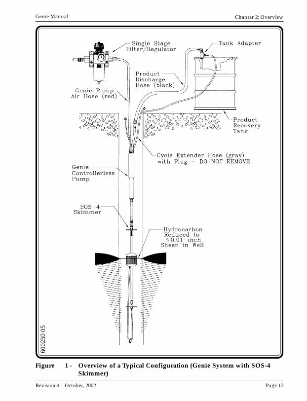
Figure 1 on the next page illustrates a Genie System using an SOS-4 skimmer.
The Genie System provides everything required for pumping fluid from the wellexcept the air source. Air is connected to the Genie by a system air supply hose and aGenie pump air hose with quick-connect fittings.
Page 13Revision 4 – October, 2002
Genie Manual Chapter 2: Overview
6002
50 0
5
Figure 1 - Overview of a Typical Configuration (Genie System with SOS-4Skimmer)
Clean Environment Equipment
Page 14
Genie Manual
The system is designed to perform for years. An automatic drain on the compressor(available from CEE) is highly recommended since it dramatically decreases air filtermaintenance.
Alteration of the System
Do not change or modify the system without the expressed written approval of CEE.To meet the many different needs of users, additional sensors can only be added tothe system by CEE.
Optional Systems/Accessories
The following options are available from CEE. Contact your regional office for moreinformation.
• Tank-Full Shut-Off (TFSO) – (See Appendix A)• High-Water Shut-Off (HWSO) – (See Appendix A)• Pump Cycle Counter – (See Appendix A)• Product Sensing Recovery (PSR) with Product Only – (See Appendix A)• Angled Wells – (See Appendix A)
Page 15Revision 4 – October, 2002
Genie Manual
Chapter 3: Equipment
Equipment List
The equipment list will vary depending on application type, but the following list isa base Genie configuration:
1. Genie Controllerless Pump consisting of:• Automatic pulser unit• Bladder pump located below pulser unit
2. Single stage filter/regulator consisting of:• 5 micron filter with auto drain trap• Pressure regulator with gauge
3. Tank adapter
4. Hoses:• Product discharge hose (black)• Genie pump air hose (red)• Air exhaust tubing (black)• Fume return/overflow hose (gray)• System air supply hose (blue)• Cycle extender hose (gray)
5. Well support system:• Well cap
6. Intake Configurations: In addition to the base configuration, there are six otherintake configurations. Based on the application type one of the followingequipment are used with the noted configurations.
a. Floating intake skimmer:• Product only
Clean Environment Equipment
Page 16
Genie Manual
b. Top-loading cup:• Total fluids
c. Inlet screen:• Dissolved and/or sinkers• Landfill fluids• Dedicated sampling (requires Teflon Bladder in the pump)• Dual pump recovery
Specifications
The following sections describe each of the basic components and the applicationsused to operate them.
Genie Controllerless Pump
Automatic Pulser Unit
The pulser combines timers and an air valve and is mounted above the bladderpump. The timer located inside the pulser governs how often and for how longthe pump is pressurized. (See Figure 2 and Figure 3)
The pulser supplies air to the pump and exhausts the pump using an internalpneumatic circuitry. This is done with one adjustment on the one unit whensetting the cycle on the pump.
With a flathead screwdriver, turn the cycle adjustment screw inside the pulserunit clockwise to increase the cycle time, and counterclockwise to decrease thecycle time.
Equip L(Inches)
O.D.(Inches)
Weight(Pounds)
Min WellID Req
(Inches)
Min AirPressure
(Psi)
222
404040
Filter/Reg 13.4 5.4 NA
Hoses See Page 22
Skimmers See Appendix C
* Higher pressure systems available.
MaxGPD
Genie:12-inch24-inch48-inch
526488
1.8751.8751.875
61113
80160320
200200200
Max Depth(Feet)
NA NA NA NA
Max AirPressure
(Psi)*
100100100
120
Page 17Revision 4 – October, 2002
Genie Manual
The Genie is preset at the factory to a 30 second cycle time using 80 psi airpressure. This means the pump is pressurized (fluid pushed out) and exhausted(fluid drawn in) within 30 seconds. If the cycle rate is adjusted to another time,ensure ample time for desired fill and discharge is allowed. The cycle time isapportioned with 30% to 35% to the pressurization phase and 65% to 70% to theexhaust phase. The shortest cycle time used is about 7 seconds, but this is rarelyneeded. If the pump is cycled more times than necessary, compressed air iswasted and the time life of the bladder (about 3 million cycles) will be shortened.The Product Recovery Rate chart in Chapter 5 shows cycle times, pump sizes,and the resulting flow rates.
Cycle times can be increased or decreased by adjusting the timing adjustmentscrew in the Genie driver, changing the volume of the Cycle Extender Hose andby varying the air pressure. All of these are discussed later in this manual.
The approximate volume per cycle of the Genie pumps are as follows:12-inch pump = 45 cc24-inch pump = 110 cc48-inch pump = 280 cc
Bladder PumpThe bladder pump attached to the automatic pulser unit removes fluids from asdeep as 200 feet at a rate of between 10 and 100 Gallons Per Day (GPD) based onthe cycle length setting. The pump is designed to draw product from a skimmerand push it up and out of the well.(See Figure 2 and Figure 3)
Note:There are two types of Genie pumps available:1. Welded construction with stainless steel ends (not shown). This
unit should be sent to the factory for service, if needed.2. Bolted construction with brass ends. (See Figure 3) This unit can
be disassembled for bladder replacement. Do not open this unitunless a CEE service representative has instructed to do so.
The single stage 5 micron air filter/regulator has an automatic drain and is mountedoutside of the well. The filter/regulator removes particles and some oil vapor, andwater droplets from the air passing to the Genie pump. The regulator shouldproduce at least as much pressure as required to move the fluid from the depth atwhich the pump is installed. (See Figure 4)
Note:Too much air pressure can result in low pump efficiency.
6002
49 0
2
Figure 4 - Single Stage Filter/Regulator
Page 21Revision 4 – October, 2002
Genie Manual Chapter 3: Equipment
Tank Adapter
The tank adapter threads into the product recovery tank to act as an intake and vent/overflow fitting. It has 3/4 inch NPT threads made of brass to reduce spark hazard.(See Figure 5)
6002
60
Figure 5 - Tank Adapter
Clean Environment Equipment
Page 22
Genie Manual
Hoses and FittingsSix types of hoses or tubes are supplied with the Genie System. The table belowshows the normal hose colors. These may change due to application or need.
Hose Color Code Table
Color/Material/Size Name Function FittingsHose: Black/Nitrile, PVCTubing: Black/Nylon or
White/PolyethyleneSize: 5/8” to 1-1/4”
ProductDischarge
Transports product from theGenie pump to the dischargepoint
Hose barb and clamp orstraight through quick-connects
Hose: Red/Nitrile, PVCTubing: Red/Nylon or
White/PolyethyleneSize: 3/8” to 3/4”
Genie Pump Air Supplies air from the singlestage filter/regulator to theGenie pump
Hose barb and clamp or one-way quick-connect fitting
Hose: Black/Nitrile, PVCTubing: Black/Nylon or
White/PolyethyleneSize: 1/4”
Air Exhaust Tube Exhausts air from the Geniepump
Hose barb and clamp orstraight through quick-connects
Hose: Blue/Nitrile, PVCTubing: Blue/Nylon or
White/PolyethyleneSize: 3/8” to 1/2”
System Air Supply Supplies air from thecompressor to the singlestage filter/regulator
Hose barb and clamp or one-way quick-connect fitting
Hose: Gray/Nitrile, PVCTubing: Gray/Nylon or
White/PolyethyleneSize: 3/8”
FumeReturn/Overflow
Returns product overflow fromthe product recovery tank tothe well
Hose barb and clamp or one-way quick-connect fitting
Hose: Gray/Nitrile, PVCTubing: Gray/Nylon or
White/PolyethyleneSize: 1/4”
Cycle Extender Increases the cycle time of theGNE driver timer
Hose barb
The cycle extender hose's upper end is sealed by a brass barb plug. The hose shouldnot be removed from the driver, nor the plug from the end of the hose, unless theoperator wishes to add a length of hose to further extend the cycle time. If a longercycle time is desired, please contact the factory.
If optional quick-connects are used, the flow of air and fluid in the hoses runs into themale plug and out of the female socket.
The quick-connect fittings will not interchange, so one cannot connect a hose to anincorrect fitting.
Page 23Revision 4 – October, 2002
Genie Manual Chapter 3: Equipment
Note:The down well hose fittings normally have locking quick-connects.On sites with water depths over 50 feet, special consideration may berequired to support the hoses. Consult with CEE regarding suchapplications.
Well Support System
To safely support the product discharge hose, Genie pump, and floating intakeskimmer, a well support system is provided.
Included in the system are a well cap (holes drilled through the cap without fittings),hose clamp, cable ties and eye bolts that secure the hose, Genie pump and skimmerin the well.
See page 49 for a description of how to connect the well support system.
Intake Configurations
SkimmersClean Environment Equipment (CEE) manufactures two types of floating intakeproduct skimmers. Both are true skimmers in that a floating intake allows theskimmer to move freely up and down within the well bore. This allows theskimmer to respond to variable product thicknesses and groundwaterfluctuation. There are two types skimmers: the Selective Oil Skimmer (SOS) andthe Specific Gravity Skimmer (SPG).
The two skimmer types differ slightly in performance, but the importantdifference is in application. The skimmer provided with this system is either anSOS or a SPG type, based on discussing the site conditions with CEE personnel.All types of CEE SOS and SPG skimmers can be used with the Genie System andare all conveniently interchangeable for maximum flexibility.
Selective Oil Skimmer (SOS)• The SOS uses a hydrophobic-oileophillic (selective) screen which repels
water but allows the passage of fuels. Product that enters through theselective screen is drawn out by the Genie pump and removed from thewell. (See Figure 6 and Figure 7)
• The SOS can remove the product layer down to a sheen (≤ 0.01 inch)provided the product is not too thick or viscous. The product should beabout SAE 20 weight or less for good performance.
• The selective screens were designed to be adaptable to the need of theuser. There is a shorter and longer lip to the selective screen. When theshorter lip is faced down, the product is removed to a sheen. When thelonger lip is down, the skimmer leaves a little more oil in the well, whichcan enhance oil movement into the well.
• The SOS is available in two sizes (2- and 4-inch diameter models).
• There are two screen sizes available (55 and 110 mesh). The 110 mesh isstandard and shipped with the SOS unless the 55 mesh is requested. The55 mesh screen is used when more viscous oils (e.g., No. 2 fuel oil) mustbe recovered.
• The SOS will resist water intrusion up to several inches of water column.If the SOS is submerged, the hydrostatic water pressure will overcomethe water repulsion ability of the screen and water will enter theskimmer. If this happens, dry the screen or wash off the water in therecovered hydrocarbon and reinstall the green inner screen into theskimmer.
• If the product contains a lot of very small suspended solids or ifbiological growth is known to be very aggressive, the outer debris screenand perhaps the selective screen on the skimmer may require periodicservice or cleaning.
Caution:Do not scrub the screen, this could destroy its selective properties.(See Chapter 6: Maintenance, page 63)
Page 27Revision 4 – October, 2002
Genie Manual Chapter 3: Equipment
Specific Gravity Skimmer (SPG)
• The SPG uses the principle of density to distinguish between water andproduct. The floating intake has a specific gravity of about 0.94 whichmakes it float in water, but sink in most products. Because productintake is on top of the float, it takes in only product.(See Figure 8, Figure 9, and Figure 10)
• By design, the SPG does not usually remove all of the product on thesurface of the water. The SPG typically leaves about 1.5 to 2 inches ofproduct in the well at all times. The amount of fuel or oil left in the welldepends mainly on the specific gravity of the product. This residualproduct can enhance the influx of additional product into the well.
• As the specific gravity of the product increases or approaches the gravityof the skimmer float, more product is left in the well. Therefore, the SPGis generally not used for skimming products whose specific gravity isgreater than 0.85. The SPG can be adapted at the factory to removeheavier products and emulsions. The user is then able to adjust theintake level of the skimmer.
• The primary application of the SPG is in the case of a significantthickness of product or in the case of more viscous or dirty products.
• The SPG is available in three sizes (2-, 4-, and 6-inch diameter models).The SPG usually requires 1.5 to 2 inches of fuel in the well to beginrecovering. If it is submerged by a high-water condition in the well, andis not controlled by the HWSO system, water will pass to the Geniepump.
Clean Environment Equipment
Page 28
Genie Manual
Figure 8 - Two-Inch Single-Rail Specific Gravity Skimmer (SPG-2SR)
6005
55
Page 29Revision 4 – October, 2002
Genie Manual Chapter 3: Equipment
6002
56 0
3
Figure 9 - Two-Inch Multi-Rail Specific Gravity Skimmer (SPG-2MR)
Clean Environment Equipment
Page 30
Genie Manual
Figure 10 - Four-Inch Multi-Rail Specific Gravity Skimmer (SPG-4MR)
6002
57 0
2
Page 31Revision 4 – October, 2002
Genie Manual Chapter 3: Equipment
Top-Loading CupUse the top-loading cup for total fluids. This fixed intake is designed to removefloating product from the top of ground water along with some water. This is atotal-fluids system which creates a cone-of-depression in the water table whileremoving the floating product. (See Figure 11)
Figure 11 - Top-Loading Cup
6006
52
Clean Environment Equipment
Page 32
Genie Manual
Inlet ScreenUse the inlet screen for the following:
• Dissolved and/or sinkers• Landfill fluids• Dedicated sampling (requires Teflon Bladder in the pump)• Dual pump recovery
By mounting an intake screen on a Genie pump, a inlet screen removescontaminated water and “sinkers” (heavier-than-water fluids). The Genie pumpand pulser can be submerged without damage. The exhaust hose outlet ispositioned above the fluid level. (See Figure 12)
Page 33Revision 4 – October, 2002
Genie Manual Chapter 3: Equipment
Figure 12 - Inlet Screen
6006
53 0
2
Clean Environment Equipment
Page 34
Genie Manual
Page 35Revision 4 – October, 2002
Genie Manual
Chapter 4: Assembly & Installation
Cautions
Note:Follow the instructions on Figure 13 (following page) for properlysecuring the locking quick-connects.
• Do not use PVC pipe for compressed air conduit. It is not considered a safe use ofthe material.
• Cover the hose ends with tape if they are being pulled through trenches. Be surethe ends of the hoses that connect to the air compressor and fluid discharge havethe correct fitting leading out of the well. If you are unsure, look at the respectivefittings on the pump.
• Blow out all compressed air conduits (trunk lines, sensor hoses, air supply hosesetc.) and fluid lines for at least 10 seconds before connecting them to the system.
• When running hoses in conduit, include a rope to pull additional hoses in casethey are needed at a later date.
• Protect the Genie from freezing conditions. If possible, maintain the temperatureabove 45° F. This is usually accomplished because the system is positioned insidethe well, which is warmed by the groundwater. Other adverse conditions such asrain, dust and vibration usually have little or no effect on the system.
• If solid metal piping is used for compressed air conduit, it is advised that an airfilter or a “Y” strainer with a fine mesh screen (a 60 mesh or greater) be placed atthe downstream end of the piping. Metal flakes, rust, galvanizing material, dirt,etc. can be dislodged from such metal piping and travel to the pump or controls.
Clean Environment Equipment
Page 36
Genie Manual
Figure 13 - Locking Quick-Connect Instructions
6002
59 0
2
Page 37Revision 4 – October, 2002
Genie Manual Chapter 4: Assembly and Installation
• Cut the tie-wrap that holds the ring weight to the bottom of the skimmer.
• Cut the tie-wrap that prevents the skimmer float from moving on the guide rodduring shipping.
Compressed Air Supply
The Genie System includes two air lines—one from the compressor to the airregulator and the other from the air regulator to the GNE system. Both have quickdisconnect fittings, unless hose barbs were specified by the client.
There is a distinct air inlet on the Genie. This fitting has a female counterpart on theair inlet hose. The air inlet must be connected for the Genie System to function. Donot lubricate the compressed air coming out of the compressor. The Genie does notrequire lubrication and excess oil may foul the filter/regulator.
The compressor should not provide more than 250 pounds per square inch (psi) of airpressure to the filter/regulator. The filter and regulator accepts a maximum of 150psi air pressure. For greater inlet pressures, a metal filter bowl would be required.Maximum air pressure setting on the regulator is 120 psi.
Cold Weather
Freezing conditions may cause problems that could that require assistance from CEE.
The Genie System was designed to solve freezing of the pump controls in cold (<40°F) weather. Since the controls are in the well with the pump, usually freezing doesnot occur because the ground water maintains the temperature in the well abovefreezing. The compressed air traveling to the well casing may need protection fromfreezing.
If you are operating the system in freezing weather, take precautions so that moisturedoes not freeze in the pneumatic lines.
Actions To Take• Use water traps and automatic compressor tank drains. These are available
at industrial distributing companies (e.g., W.W. Graingers®).
• Bury air hoses below the frost line. Insulate and heat with heat tape or runthrough a PVC pipe with warm air being blown through it.
Clean Environment Equipment
Page 38
Genie Manual
• Remove all the moisture you can from the air by using drains on thecompressor, filter, and low points in the air line. Use an electrical ordesiccant air dryer, and pull only cold, dry air into the compressor.
• During freezing conditions regulators may fail “open”, allowing highpressure (e.g. 150 psi from the compressor) to enter components (e.g. gauges,hoses, fluid receptacles) that may be damaged, cause a safety problem, orrelease contaminating material. Be sure the regulator is protected fromfreezing.
• A pneumatic or electric air drier can be installed between the air compressorand control box. This unit reduces the water content of the air socondensation and freezing is reduced significantly. If an electric air drier isused, it must be outfitted with explosion-proof controls or placed away fromthe Genie pump and product recovery tank.
Base Configuration Component Assembly
STEP 1 - Install Genie Pump Air Hose (red)
a. Attach the male fitting of the Genie pump air hose to the singlestage filter/regulator. (See Figure 14)
b. Attach the female fitting of the Genie pump air hose to the airsupply fitting on the Genie pump.
STEP 2 - Install Air Exhaust Tubing (black)
a. Push the air exhaust tubing into the red-collared tubing fittingon the pump. (See Figure 14)
b. Secure the exhaust tubing to the air hose and the cycle extenderhose with a cable tie so it does not wander freely in the well.
STEP 3 - Install Tank Adapter
a. Thread the tank adapter into a 3/4 inch NPT fitting on the top ofthe product recovery tank. (See Figure 14)
Page 39Revision 4 – October, 2002
Genie Manual Chapter 4: Assembly and Installation
STEP 4 - Install Fume Return/Overflow Hose (gray)
a. Attach the fume return/overflow hose to the tank adapter viahose barb and clamp. (See Figure 14)
Note:Additional holes can be drilled in the well cap to accommodateadditional hoses.
STEP 5 - Install Product Discharge Hose (black)
a. Attach the female fitting of the product discharge hose to thetank adapter in the product recovery tank.(See Figure 14)
b. Attach the male fitting of the product discharge hose to theGenie pump.
STEP 7 - Install System Air Supply Hose (blue)
a. Thread the air hose socket with 1/4 inch MPT to the compressor.Use teflon tape or sealant on the threads.
b. Attach the air hose plug end of the system air supply hose to thesocket now attached to the compressor.
c. Attach the socket on the discharge end of the hose to the singlestage filter. (See Figure 14)
In addition to the base configuration, there are six intake configurations depending onsite specifics and application. First assemble the base configuration. Next, find theappropriate heading below, and then follow its instructions.
Product Only• Attach the Skimmer to the inlet of the Genie pump.
(See Figure 14)
Total Fluids• Connect the male fitting on the end of the Genie bladder pump intake hose
to the female fitting on the top-loading cup. (See Figure 15)
Clean Environment Equipment
Page 40
Genie Manual
6002
41 0
5
Figure 14 - Genie System with Floating Intake Skimmer (for Product Only)
Page 41Revision 4 – October, 2002
Genie Manual Chapter 4: Assembly and Installation
6006
55 0
2
Figure 15 - Genie System with Top-Loading Cup (for Total Fluids)
Clean Environment Equipment
Page 42
Genie Manual
Dissolved And/Or Sinkers• Thread the inlet screen screened intake on the inlet of the Genie pump.
(See Figure 16)
Note:A special bladder may be required for aggressive chemicals
Landfill Fluids• Thread the inlet screen screened intake on the inlet of the Genie pump.
(See Figure 16)
Dedicated Sampling (Requires Teflon Bladder)• Special connections and material should be used if such sampling needs to
be used for compliance sampling. A Teflon Bladder should be used in thepump. The pump should have stainless steel and Teflon for all wettedcomponents. Any fluid intake and discharge tubing should be Teflon orTeflon-lined.
• The GNE driver is either supported away from the pump and Teflon tubingis run around it to carry the sampled fluid out of the well, or special stainlesssteel ends, Teflon tubing and hose barbs are built into the GNE drivermodule, so the fluid can flow through the unit.(See Figure 16)
• The inlet screen is threaded onto the intake of the pump or, if an intake tube(drop tube) is used, attached at the bottom of the intake tube.
Dual Pump Recovery
• Attach the skimmer to the male product hose quick connect fitting beneaththe Genie pump. (See Figure 17)
• Water is removed with an automatic Double Diaphragm Pump (DDP) or anAutoPump (AP). The skimmer is used to attach the water draw down sensoror it is strapped alongside the bottom loading AutoPump(AP/BL) with the trigger level of AP at 4 inches above the lowest level of theskimmer intake. (See Figure 17)
• A GNE-HW control box is optional. This would use a sensor off the GNEcontrol if the water table were to rise. This would prevent water beingpumped by the GNE system if the oil skimmer became submerged.
Page 43Revision 4 – October, 2002
Genie Manual Chapter 4: Assembly and Installation
Figure 16 - Genie System with Inlet Screen (for Dissolved, Sinkers, andLandfill Fluids)
6007
78 0
2
Clean Environment Equipment
Page 44
Genie Manual
Figure 17 - Genie System with Dual Pump Recovery: (AP-4),Tank-Full Shut-Off (TFSO), and High-Water Shut-Off (HWSO) Systems
6002
75 0
5
Page 45Revision 4 – October, 2002
Genie Manual Chapter 4: Assembly and Installation
• The following hoses are included with the dual pump recoveryconfiguration:
- Water suction hose- Water discharge hose- Water pump air hose
Dry Test
Before installing the skimmer and Genie pump assembly in the recovery well, it isimportant to test the Genie System for proper operation. Before beginning this test,make sure that all hoses are properly connected as described in the previous section.
STEP 1 - Turn on the Air Compressor
• Turn on the air compressor. Allow it to charge the reservoir tankand automatically turn off.
STEP 2 - Connect the Air Hose to the Genie
• Connect the system air supply hose to the Genie pump.
• Ensure that there is at least 40 psi to the Genie System.
STEP 3 - Test the Automatic Pulser Unit
• Allow the pulser unit to pressurize and exhaust itself.
STEP 4 - Check the Cycle Rate
• The cycle rate has been factory set between 15 and 25 seconds forthe complete pressure/exhaust cycle at 80 psi.
Clean Environment Equipment
Page 46
Genie Manual
STEP 5 - Test the Suction and Discharge
• Test for suction and discharge pressure at intake and dischargeof Genie. Remove the skimmer from the intake end of the pumpand the discharge hose from the discharge end. Because thequick-connect fittings have internal valves, they must have theirmating fittings be attached or be removed before a suction orpressure can be felt or measured. Pressure can be felt by closingoff the inlet with a thumb, or a vacuum gauge can be attached.
• The discharge pressure can be felt in the same manner, or byattaching a pressure gauge to the discharge. Which ever end isbeing tested, the other end should be open so there is noresistance to building up pressure or discharge. To measure themaximum pressure, the pump should be filled with water.
If the Genie System does not pass this test, check all fittings and hoses to make surethey are not twisted and that all connections are correct.
Adjust the pulser to desired rate and allow it to cycle several times.
Hose Bundling Assembly
In addition to supporting the down-well equipment with a support rope, it isimportant to support the down-well hoses. In many cases the down-well hosesweigh more than the equipment itself, particularly in wells over 50 feet deep withfluid inside the discharge hose. Hose support is necessary to avoid the followingproblems:
• Hoses may kink at the pump• Hoses could coil and get caught in the well• In some cases the hoses are supporting the down-well equipment leaving the
support rope hanging free in the well, placing tension on the hoses.• Tension on the hoses may exceed its design limits
Hose bundling reduces equipment entanglement at the well surface, and aids theremoval of the pump from the well. Bundling also assists in positioning the pumpand down-well hose assembly against one side of the well casing. Maximum space iscreated for other items, such as probes, to be periodically placed inside the well.
Page 47Revision 4 – October, 2002
Genie Manual Chapter 4: Assembly and Installation
For well caps without barbs or compression fittings (e.g. holes through which thehoses or tubing pass), a support rope needs to be used to prevent kinking of thehoses as they pass up and out of the well cap. For depths less than 50 feet, Bundlethe hoses with the support line every 10 feet to within 3 feet of the top of the well.(See Figure 18)
Following these instructions to create a hose bundle.
With a cable tie, bundle the air, product, cycle extender, and exhaust hoses together.The product hose is used to support the system and the other hoses. With its steelreinforcing, the product hose will not stretch or break from the weight. The GNEsystem can be supported by the product hose.(See Figure 18)
You now have a down-well bundled hose assembly that supports both the hoses andthe down-well equipment.
Clean Environment Equipment
Page 48
Genie Manual
6007
85
Figure 18 - Hose Bundling
Page 49Revision 4 – October, 2002
Genie Manual Chapter 4: Assembly and Installation
Genie InstallationThis section describes the installation of the Genie pump, skimmer, and well supportsystem.
Once the assembly and hose bundling of the Genie pump and skimmer arecompleted, you may begin to install them in the recovery well. If the recovery well ismuch larger than the skimmer, we strongly suggest that a well screen sheath be used.This protects the skimmer from hanging up on the other hoses in the well. A 2-inchskimmer will need a 2-inch sheath, a 4-inch skimmer will need a 4-inch sheath, and a6-inch skimmer will need a 6-inch sheath. (PVC well casing can be used for sheaths.Perforated stainless steel tubing can be used if the PVC well casing will not fit.)
STEP 1 - Lower Genie Controllerless Pump and Skimmer into Well
• Lower the skimmer and Genie pump down the recovery welluntil the midpoint of the skimmer’s guide tube(s) is located atthe fluid level in the well. This provides the skimmer with amplerise and fall travel to accommodate reasonable fluctuations in thewater table.
For product thicknesses of 6 to 12 inches, the midpoint of theguide tube(s) can be positioned halfway into the product. Forthicker layers, the position can be calculated using the specificgravity of the product.
i. Multiply the specific gravity of the product times theproduct thickness.
ii. Subtract the above result from the depth-to-water. Placethe midpoint of the guide tube at this point.
Example:
• Gasoline with a specific gravity of 0.75 is in a 5 foot thick lens. The waterlevel (below the product) is 10 feet below ground level. The midpoint ofthe Selective Oil Skimmer guide tube should be positioned [10 - (.75 x 5)]or 6.25 feet below ground level.
• When the specific gravity of a product is not known, use 0.8. Gasolinewill generally be in the range 0.70 to 0.75, while diesel oil is 0.8 to 0.85.The specific gravity of a leaked product will increase over time due tothe loss of the lighter weight hydrocarbons to the soil, water andevaporation.
Clean Environment Equipment
Page 50
Genie Manual
STEP 2 - Install Well Support System
• Using the well support system (See Figure 19), secure theproduct discharge hose at the top of the well by one of thefollowing methods depending on clearance and ability to make acut in the well casing:
- Secure the product discharge hose to the eye bolt in tothe well cap with either a hose clamp or cable tie.
- Secure the product discharge hose with either a hoseclamp or cable tie to a 1/4 inch steel pipe and rest thepipe across the well casing.
- Put a 1/2 inch wide notch in the well casing and tightenthe hose clamp around the out-of-well end of theproduct discharge hose where you want to hold the hoseat the notch. The hose clamp prevents the hose fromslipping through the notch and thereby lowering theGenie pump and skimmer into the well. Replace thewell cap over the well casing to secure hose.
Note:The product discharge hose supplied by CEE will not stretch or kinkfrom the weight of the skimmer and Genie pump.
Page 51Revision 4 – October, 2002
Genie Manual Chapter 4: Assembly and Installation
6002
63 0
2
Figure 19 - Well Support System
Clean Environment Equipment
Page 52
Genie Manual
Page 53Revision 4 – October, 2002
Genie Manual
Chapter 5: Start Up and Operation
Start Up Checklist
In normal operation, the Genie System requires little attention. Conduct a routineinspection of the product recovery tank to record the rate of product recovery and toensure that water is not entering the skimmer.
Before regulating the air pressure to the desired operating pressure, ensure thefollowing exist:
1. Safety equipment is being used by all personnel.
2. All hoses are connected.
3. The air filter is mounted vertically to allow the filter to operate properly.
4. All out-of-well air and fluid valves are in their correct positions.
A method of rapid disconnect and exhaust (or at least a shut off) of compressed air tothe pump is available in case of an unexpected occurrence.
Only the automatic pulser unit potentially needs to be adjusted to fit the siteconditions. Everything else is automatic.
Clean Environment Equipment
Page 54
Genie Manual
Adjusting Genie Cycling
First determine what cycle rate is needed to obtain the desired flow rate by using thechart below. The effects of using the adjustment screw in the Genie pulser, theaddition of hose and changes in pressure are discussed below.
Adjusting Cycle Rate By Using the Adjustment ScrewThe cycle adjustment screw has about 5-1/2 turns from full open to full closed.All settings are measured from full open (where the screw stops when turningcounterclockwise). Beyond 4 turns from full open, the opening in the air passagebecomes very small and timing may be shut off entirely. It is recommended theadjustment be set between 2 to 3-1/2 turns from full open. With the five footCycle Extension Hose, with 80 psi supply pressure this provides a cycle timerange from about 10 seconds to about 90 seconds. An increase of 20 psi willincrease the cycle time about 8 to 9%. A decrease of 20 psi will decrease the cycletime the same amount.
STEP 1 - Remove the exhaust tubing from the head of the pump bypushing on the red collar and pulling on the tubing.
STEP 2 - Slower or Faster: Insert a small flathead screwdriver (0.25-inchwide, 6-inch long - included with the system) through theexhaust fitting on top of the pulser unit and into the cycleadjustment screw in automatic pulser unit. To slow down thecycling rate (decrease the pump rate), turn the cycle adjustmentscrew clockwise. To speed up the cycle rate (increase the pumprate), turn the screw counterclockwise. (See Figure 2 on page 18)
Note:Beyond 2 turns from full open, the adjustment should be done in1/4 to 1/2 turns of the adjustment screw. Larger adjustments mayslow down or speed up the cycle rate too much. See the table belowfor examples of settings.
Page 55Revision 4 – October, 2002
Genie Manual
STEP 3 - Time the cycle rate for two complete cycles to ensure it is whatyou want and then replace the exhaust tubing into the push-lockfitting in the head of the pump.
It is recommended that the cycle time is set between 15 and 60 seconds. Thefurther closed the adjustment screw is turned the smaller the timing airpassage will be. Too small an opening can result in debris being trapped inthe opening and severely changing the cycling rate.
With the standard five foot 1/4-inch Cycle Extender Hose and an air supplyof 80 psi, the following are the approximate cycle times to be expected at therespective adjustment screw settings:
Turns From Full Open Cycle Time in Seconds
Note:All cycle times given here are approximate due to the variations inadjustment screw, adjustment screw seat and air passageconstruction in the pulser unit. Humidity and temperature will alsoaffect cycle timing.
Additional hose added to the Cycle Extender Hose will result in longer cycletimes without changing the adjustment screw setting.
Example: With an air supply pressure of 80 psi and an adjustment screwsetting of about 3 turns from full open:
• For every ten feet of 1/4-inch I.D. hose, the cycle time increases by about70 seconds.
• For every ten feet of 3/8-inch I.D. hose, the cycle time increases by abouta 3 minutes.
• For every ten feet of 1/2-inch I.D. hose, the cycle time increases by abouta 4.5 minutes.
1 4
1.5 10
2 16
2.5 25
3 42
3.5 110
4 570 (9.5 minutes)
Chapter 5: Start Up and Operation
Clean Environment Equipment
Page 56
Genie Manual
To set the adjustment screw for very long cycles, the increase in cycle timecan be estimated by using the ratios between the 3 turns setting and thegreater turn settings.
Example: A 3.5 turn setting with 20 feet of 1/2-inch hose and 5 feet of1/4-inch hose will render a cycle time of about 2 X 110/42 (4.5 minutes.) +110 seconds ≈ 25.4 minutes.
Product Recovery Rates
Cycle Time Gallons Per Gallons Per Gallons PerDay (GPD) Day (GPD) Day (GPD)12-inch Pump 24-inch Pump 48-inch Pump
* At such short cycle rates, the pumps in these categories could not fill and emptycompletely. A Genie using a four-inch skimmer (SOS-4 or SPG-4) may be needed toobtain these values.
All flow rates are dependent upon the availability and viscosity of the product, thedepth to the water table, the air pressure to the system, flow resistance and thepressure in the receiving piping. When pumping gasoline, all CEE skimmers arecapable of delivering the flow rates in the tables. If greater flow rates are desired,consult the factory.
The Genie System cannot remove product faster than the soil will give it up. Mostspills are recovered at less than 30 gallons per day.
Using a standard Genie Cycle Extender Hose of 1/4 inch I.D. and 5 feet long, theaverage air use per cycle in standard cubic feet is:
For larger or smaller Cycle Extender Hoses add or subtract the difference in volumeof the hose multiplied by the compression ratio of the air pressure(i.e. 1+ psi/14.7) to obtain the difference in air use.
Observation of System Operation
After installing the system in the well, listen for the cycling of the pulser unit. Bylistening near the well, the exhaust cycle should be audible. Monitor the output ofthe fluid hose by removing the tank adapter and holding the output over the openingin the tank. If the product is flowing easily into the skimmer, a 1/4-inch I.D. producthose will fill at the rate of about 10 feet per cycle (using a 24-inch bladder pump).Thus a 100 foot hose may require 10 cycles before any fluid exits the hose.
It may be advisable to leave the tank adapter in a bucket until product appears. Thetime required for product to be first discharged depends on the pump size, hose sizeand length, cycle rate, and the amount of product available.
After the entire site is operating, return to each well to ensure that the pump isfunctioning properly. The addition of other pumps and possible system backpressure may necessitate air pressure readjustment.
Special Operating Conditions
Conditions may exist that require adjustment or adaptations to the equipment.Below is a list for some of these conditions, their possible effects and a briefdescription of an adjustment which may solve the problem.
Since every site is different, please contact CEE for detailed assistance if needed.
1. The well is under a vacuum: The pump will operate normally if the air exhaust isin the well. If the air exhaust is ducted outside the well to atmospheric pressure,the pump must be submerged far enough so the weight of the fluid entering thepump overcomes the pressure differential between the well and the atmosphere.However, the pump can produce over 15 inches Hg and should function undernormal well vacuum.
2. Abrasive particles in the well: These may cause excessive wear on the checkvalves and other parts of the pump. Material changes to resist abrasion can bemade. A filter “sock” can be placed over the pump intake to filter out theparticulates. This does not apply to skimmers. A finer mesh inlet or debris screenmay be used on skimmers.
Clean Environment Equipment
Page 58
Genie Manual
3. Aggressive chemicals and/or corrosive environments: These may cause pumpparts to deteriorate. Material changes can be made and sacrificial anodes can beadded.
4. Hard pipe connection to the pump: These can cause debris and scale to traveldown to the pump. It can also prevent the pump from cycling smoothly due to asolid connection (non-flexing) to the top of the pump. Blow out all of the hardpipe before connecting the pump. A short (6 feet) length of hose should be usedbetween the hard pipe and the pump to allow the natural movement of the pumpto occur without restraint.
Other site conditions such as highly viscous materials, deep (>200 feet)applications, high flow rates for LNAPL application, intermittent air supply, highdissolved solids and high temperature can be addressed also. Please contact CEEfor guidance.
Genie Shutdown and Removal
If the Genie is to be shut down and left in the well, raise the pump above the highestfluid level and shut off the air to the pump. Also close the fluid discharge valve ifone is present. The Genie can be submerged for short intervals without damage.
Page 59Revision 4 – October, 2002
Genie Manual
Chapter 6: Maintenance
General Maintenance
The Genie System should be relatively free of maintenance. The frequency ofmaintenance depends upon the nature of the fluids being pumped. Following aresome general maintenance checks that can be done periodically.
• Periodically inspect all hoses and connections for damage. Make sure that thehoses are not split or cracked and listen for leaks in the system.
• Soapy water can be sprayed (using a squirt bottle) on the components and fittingsto locate leaks. Dish detergent in water will not damage the system.
Caution:Do not get soapy water on a skimmer’s selective screen. Soap causesthe screen to lose its hydrophobic properties. Rinse and dry thescreen to return its hydrophobic properties.
• However, if water enters the Genie pump via the compressed air (from thecompressor), it can cause the pulser unit to malfunction. The unit can stall in thepressurizing mode. Most of the time this does not cause a problem, but if it does,use a clean, dry air source to blow out the system. Remove the small drain plugfrom the intake end of the Genie pump and blow out any oil and moisture thatmay have accumulated in the pump. Once the controls begin functioning, checkthe pulser and allow the system to operate for an hour before returning it toservice.
• Even if a little oil and water enters the air hose, the Genie System should performreliably for years.
Clean Environment Equipment
Page 60
Genie Manual
• Check the air filter and filter bowl drain on the single stage filter/regulator forsaturation and operation every few weeks.
• Drain the air filters on the air hose to the pumps of collected particles, water andoil periodically to prevent the filter from clogging up or being otherwise damaged.Check the regulator to ensure the pressure setting has not drifted appreciably.
• An automatic drain on the compressor is highly recommended, since such anaddition can dramatically increase air filter life and decrease maintenance.Automatic drains are available from CEE.
Maintenance Table
Maintenance is recommended at least once every two weeks, but some siteenvironments may demand more frequent service. The following table outlines therecommended minimum maintenance schedule for the Genie System.
Maintenance Weekly Biweekly
Air Quality Check- Single Stage Filter/Regulator
Check Genie Pump
Check Skimmers- SPG Skimmer- SOS Skimmer
X
X
XX
The following sections describe each of these maintenance activities in detail.
Air Quality CheckSingle Stage Filter/Regulator MaintenanceIf the incoming air is clean and dry, the AutoPump System should operatetrouble-free for years. The air filter is normally a 5 micron filter with areplaceable element.
Page 61Revision 4 – October, 2002
Genie Manual
To replace the element in the air filter on the single stage filter/regulator use thefollowing procedure:
STEP 1 - Disconnect Air Source
• Valve off the air supply and drain the downstream air to the airfilter. Or disconnect the blue system air supply hose from thesingle stage filter/regulator. The air filters will depressurize,allowing them to be safely serviced.
Warning:Do not remove a filter bowl that is pressurized.
STEP 2 - Remove Filter Bowl
• Remove the bowl of the air filter by sliding the black buttondownward and twisting the bowl about 1/10 of a turn. Thebowl should slide downward from the upper portion of the filterrevealing the filter element. Unscrew the element as you wouldunscrew a light bulb. Hand tighten the element after replacingit.
• Make sure to replace the correct element.
- The 5 micron particulate filter was reddish-brown up until1994.
- The new elements are white.Large Filter (FR 60): CEE Part No. FRP-95-160-Series ASmall Filter (FR 35): CEE Part No. FRP-96-729
STEP 3 - Bowl Drain
Optional Float Drain
• Wash out any deposits and oil buildup from the filter bowlwith warm water and soap. To make sure the float drain isoperating freely, shake it; the drain should rattle. Test thefloat drain by filling the bowl with water, assembling thebowl to the filter and reconnecting it to the air supply. Thewater should drain from the bowl. When under pressure,the drain should not leak.
Chapter 6: Maintenance
Clean Environment Equipment
Page 62
Genie Manual
Standard Manual Drain
• With water in the bowl, open the drain and ensure the liquiddrains easily. When under pressure and closed, the drain shouldnot leak.
Check Genie Pump
Check the Genie pump to ensure it is cycling properly and moving material. Checkthe suction vacuum and discharge pressure by connecting a vacuum gauge to theintake of the Genie pump and opening the discharge to atmosphere. Afterwards,open the intake and place a pressure gauge on the outlet. These gauges and fittingsare available from CEE.
With the discharge open, the pump should produce at least 15 inches Hg vacuum.Connect a pressure gauge to the discharge with the intake open and in water and theGenie pump full of water. The generated discharge pressure should be within 30 psiof the air pressure to the Genie pump.
With only air in the pump, the Genie should be able to produce over 60 psi using 100psi air pressure.
Note:There are two types of Genie pumps available:1. Welded construction with stainless steel ends (not shown). This
unit should be sent to the factory for service, if needed.2. Bolted construction with brass ends. (See Figure 3) This unit can
be disassembled for bladder replacement. Do not open this unitunless a CEE service representative has instructed to do so.
It is rare that the bladder requires service.
Page 63Revision 4 – October, 2002
Genie Manual
Cleaning Skimmers
Specific Gravity Skimmer (SPG)• The Specific Gravity Skimmer can be hosed off, scrubbed, or steam cleaned
without damage.
• This skimmer can be left for weeks without servicing depending on thewater iron content.
• Normal service includes ensuring the skimmer travels freely, passes fluideasily through itself and its flexible tubing, and that no leaks exist.
Selective Oil Skimmer (SOS)• The Selective Oil Skimmer requires care in cleaning and should be checked
about once per week. The selective screen should not be scrubbed becausethe water-repulsive coating may be damaged.
• If the selective screen is passing water, the skimmer can easily be taken apart.The recommended way to clean the screen avoids brushing, rubbing orabrasion.
STEP 1 - Soak the screen and gently shake it in the hydrocarbonproduct being recovered.
If the hydrocarbon is viscous and the screen is still notadequately clean, an additional soaking and shaking in a lighterhydrocarbon, such as gasoline, is recommended.
STEP 2 - Use soft rubber gloves to avoid accidental screen abrasion byfinger nails.
STEP 3 - Direct a brief low pressure air blast around 15 psi from the insideof the screen out.
Caution:Be careful to blow fluids away from you and others around you anddo not breath the fumes.
Chapter 6: Maintenance
Clean Environment Equipment
Page 64
Genie Manual
STEP 4 - Wash off any biological growth from the skimmer.
Caution:Do not use soap on the selective screen unless it is thoroughly rinsedand dried after doing so.
On rare occasions, even with using the cleaning procedure, the screen may contain somedifficult to remove debris. Follow these instructions:
STEP 1 - Use soft gloves or some other gentle nonabrasive material tovery gently rub both the inside and outside of the screen. Thisremoves the excess debris.
STEP 2 - Soak the screen and gently shake it in the hydrocarbon productbeing recovered.
Caution:Replace the selective screen making sure it rests on the gasket andthat the wide end of the screen faces up.
Replace the float and outer debris screen on the skimmer makingsure the open end of the float’s fluid slot faces up.(See Figure 7 on page 25)
STEP 3 - It is imperative that the doughnut shaped white or black gasketbe positioned in the skimmer base prior to reassembling theskimmer.
Also, the cap nut should be threaded hand tight, puttingpressure on the selective screen below, but not to the point wherethe dome cap is being crushed or indented.(See Figure 7 on page 25)
Page 65Revision 4 – October, 2002
Genie Manual
Chapter 7: Troubleshooting
Problems may occur and usually can be easily resolved by following theseinstructions. If you need assistance, please do not hesitate to call the CleanEnvironment Equipment (CEE) Service Department at (800) 537-1767.
Troubleshooting
I. Problem: System Not CyclingSteps to take:
STEP 1 - Check that the air pressure reaching the Genie system is greaterthan any system back pressure by 30 psi.
STEP 2 - Check the timing adjustment by backing it out(counterclockwise) several turns and then turning it in to set thecycle time.
STEP 3 - Put the plugged end of the cycle extender hose under water. Ifbubbles are coming from the plug, tighten it or remove it andreplug the hose. The hose must not leak if the driver is to cycle.
STEP 4 - There may be water or oil in the pulser unit. Pull the system outof the well.
a. Unscrew the small 10-32 drain plug at the fluid intake end of theGenie pump.
b. Let the system blow air and fluids out of the drain hole for aminute.
c. Disconnect the system air supply from the single stage filter/regulator.
d. Return the plug and turn the machine on.
END OF SECTION I.
Clean Environment Equipment
Page 66
Genie Manual
II. Problem: Genie Is Pumping Water With TheProduct
Steps to take:
STEP 1 - Check if the floating intake head of the skimmer is free to movevertically in the well.
STEP 2 - Check for kinks in the flexible tube below the skimmer,obstructions on the skimmer tubes, and excess weight on theskimmer. Check for leaks in the following locations:
• the seal between the selective screen (on SOS only) and thegasket
• between the flexible tube and its hose barbs• in the flexible tubing• the check valve and fittings
STEP 3 - Hand tighten the Selective Oil Skimmer nut to ensure screen issealing on the gasket. In addition, tighten all fittings and replaceflexible tube if a hole is found. Do not overtighten skimmer nut!(See Figure 7 on page 25)
STEP 4 - Replace or clean the Selective Screen. (See page 63)
END OF SECTION II.
III. Problem: System Is Cycling, But Not PumpingFluid
Steps to take:
STEP 1 - Check if air is getting to the pump:
Listen to the cycling of the system. If the exhaust is at least 1second long, air is reaching the pump.
By holding the bladder pump it in your bare hand, the vibrationcaused by the passage of air can be felt and heard.
Page 67Revision 4 – October, 2002
Genie Manual Chapter 7: Troubleshooting
STEP 2 - Check if the pump is drawing a suction by listening to theskimmer while the pump is cycling. The sound of drawing thelast bit of liquid through a straw should be heard.
OR
Open the inlet to the bladder pump by inserting a female fittinginto the male fitting. Ensure that the discharge is open.
Feel the intake suction by putting your finger over the intake.The suction can be measured by attaching a vacuum gauge onthe intake fitting.
STEP 3 - Check if the Genie pump is pushing anything out:
a. First - Disconnect the male quick-connect on the product hosefrom the Genie pump’s female quick-connect. Ensure the pumpinlet is open and clear.
b. Second - Insert a male plug into the female end to open it up andattach a pressure gauge.
Pressure should build up over two or three cycles. Note theremay be a closed valve, crushed hose or obstruction downstreamof the pump. Ensure all discharge conduits on the site are open.
STEP 4 - Inspect the pump check valve for malfunctions:
a. Open the inlet to the bladder pump and clean the check ball andseat.
b. Clean the upper check valve on the top of the Genie System byremoving it and blowing out the debris with compressed air.
In some of the earlier Genie Systems (serial number 940901 and lower) an additionalcheck valve exists between the bladder pump discharge and the pulser unit mount.The upper stainless steel sleeve must be removed and the mount removed from thebladder pump to reach this check valve. It is rare that such a repair is requiredbecause the check valve on the upper end of the bladder pump should suffice forboth valves.
END OF SECTION III.
Clean Environment Equipment
Page 68
Genie Manual
Returning Equipment for Service
If the equipment needs to be returned to CEE for servicing, please follow these steps:
STEP 1 - Call the CEE Service Department and obtain a Return MaterialAuthorization (RMA) number. Please have available thecustomers contact person’s name, company name and address,phone number, fax number, reason for the return, and the namesof the chemicals to which the equipment has been exposed.
STEP 2 - Clean all equipment before shipping. See Equipment CleaningRequirements at the end of this section.
If the equipment must be cleaned after it arrives at CEE, thecustomer will be charged for the cleaning and disposal ofmaterial, if necessary. (Cost can be $200.00 per piece ofequipment cleaned.) Drain and dry all equipment after cleaning.
STEP 3 - Package the equipment so that it will not be damaged inshipment. Use bubble pack rather than styrofoam flakes aspacking material.
STEP 4 - Ship the equipment via a carrier and service level (i.e., one-day,two-day shipping) in consideration of probable service time andreturn shipment time.
STEP 5 - It is recommended that such shipments be insured so if theshipment is badly damaged or lost, the customer can replace theequipment at little or no cost.
STEP 6 - Include the contact’s name, company, phone number and RMAnumber given by CEE .
STEP 7 - Write the RMA number on the outside of the packaging so it willbe directed immediately to the CEE Service Department.
Page 69Revision 4 – October, 2002
Genie Manual Chapter 7: Troubleshooting
Equipment Cleaning Requirements
If the equipment is to be shipped to another site or to the factory for service, it needsto be thoroughly cleaned before leaving the site. Cleaning the equipment protects theuser (sender), the shipper, and the receiver from dirt and/or contaminants. If theequipment is not cleaned prior to shipping for servicing, it may be severely delayed,refused or the shipper may be charged a cleaning fee. Before packing and shipping,ensure that the equipment is dry inside and out.
The following is a list of equipment and how it should be cleaned prior to shipment.
Skimmers
Note:With a Selective Oil Skimmer (SOS), remove the selective screen fromthe skimmer before using soap on the skimmer.
STEP 1 - Pump clean water or water with a gentle soap solution throughthe skimmers to remove free product and particles.
STEP 2 - Rinse all soap off of the equipment.
STEP 3 - Soak and rinse the outside of the unit with water to remove loosedebris and dirt.
STEP 4 - Steam clean inside and out to remove difficult dirt andcontaminants.
Caution:Use low pressure (less than 40 psi) when steam cleaning.
Clean Environment Equipment
Page 70
Genie Manual
Bladder PumpsSTEP 1 - Pump clean water or water with a gentle soap solution (e.g.
Dove Dish Soap) through the pump to remove free product andparticles.
STEP 2 - Rinse all soap off of the equipment.
STEP 3 - Soak and rinse the outside of the unit with water to remove loosedebris and dirt.
STEP 4 - Steam clean inside and out to remove difficult dirt andcontaminants.
Caution:Do not steam clean the inside of the pump, as it may damage thebladder.
Hoses and FittingsSTEP 1 - Pump clean water or water with a gentle soap solution (e.g.
Dove Dish Soap) through the pump to remove free product andparticles.
STEP 2 - Rinse all soap off of the equipment.
STEP 3 - Soak and rinse the outside of the unit with water to remove loosedebris and dirt.
STEP 4 - Steam clean inside and out to remove difficult dirt andcontaminants.
Caution:Use low pressure (less than 40 psi) when steam cleaning.
Appendix A: Optional Systems/Accessories
Page 71Revision 4 – October, 2002
Genie Manual
Appendix A: Optional Systems/Accessories
The following options may be added to the Genie System at any time. Contact yourregional CEE office for more information.
Tank-Full Shut-Off (TFSO)The TFSO System shuts down the Genie System in the event of a liquid level rise or apressure increase in the product recovery tank. This system guards againstcontaminants in the compressed air supply, vandalism, inexperienced operators andaccidental damage to the equipment. If any of the quick-connects are removed, thesystem will shut down. (See Figure 20)
• Included in the TFSO option is a TFSO control box with tank-full indicator andtank-full reset button.
• Also included are a dual TFSO sensor hose and TFSO tank unit. The hose runsfrom the control box to the tank unit on the product recovery tank.
• A fume return/overflow hose runs the overflow from the tank unit back into thewell.
• Please see the Tank-Full Shut-Off (TFSO) manual for additional information.
High-Water Shut-Off (HWSO)A High-Water Shut-Off (HWSO) option may be added to the Genie System. If a high-water condition exists that causes the skimmer float to rise to its upper range oftravel, air is turned off to the Genie pump. This prevents water from entering theproduct line. When the water level drops back to the normal range, the skimmerfloat starts dropping with the lower water level and the air is turned back on to theGenie pump.
Clean Environment Equipment
Page 72
Genie Manual
6002
51 0
4
Figure 20 - Genie System with Optional Tank-Full Shut-Off (TFSO) Systems
Appendix A: Optional Systems/Accessories
Page 73Revision 4 – October, 2002
Genie Manual
• Included with the HWSO option is a well level sensor hose (yellow). This hoseruns from the control box to the skimmer to sense the fluid level in the well.
• Also included is a High-Water Shut-Off (HWSO) indicator. This indicator islocated on the outside of the control box. When the indicator is green, the systemis ON; when the indicator is red, the fluid in the well has risen 11 inches above thelevel sensor bubbler hole on the skimmer, and the automatic cycling of the pumphas been stopped. If more than one skimmer is being used, the operator mustselect the one to have the well level sensor hose. Unless the controls are modified,only one skimmer can be monitored.
Pump Cycle Counter
A CEE Pump Cycle Counter (PCC) can be installed in the Genie pump air line. ThePCC will increment its counter one unit each time the Genie pump cycles.(See Figure 21)
Product Sensing Recovery (PSR) with Product Only
A special sensor/skimmer combination is available if the user only wants the Genieto operate when there is product in the skimmer. Please contact the factory forinformation.
Angled Wells
The Genie System is capable of operating in slanted and horizontal wells as a totalfluids system. Please contact the factory for more information on this application.
Clean Environment Equipment
Page 74
Genie Manual
6004
47 0
3
Figure 21 - Pump Cycle Counter
Appendix B: Air Compressor
Page 75Revision 4 – October, 2002
Genie Manual
Appendix B: Air Compressor
Installation
The air compressor provides the air necessary to drive the system. The compressedair normally passes through a single stage filter/regulator and then into the Genie.
Warning:The air compressor and any other electrical equipment used withthis pneumatic system must be positioned outside of any areaconsidered hazardous because of the possibility of the presence ofcombustible materials.
Compressors start and stop automatically. Do not place hands orobjects on or near any part of the compressor.
Clean Environment Equipment (CEE) does not usually supply the air compressor. It isbest to buy the compressor from a local supplier who provides service. Follow theinstructions that accompany the compressor. This appendix is only a general guide,not an in-depth manual for the compressor.
Warning:When compressing air, parts of a compressor can get very hot. Donot touch the motor, compressor or piping until it has cooled down.
Caution:The air compressor should be located outside and away from anyarea which may contain flammable fumes.
Note:An automatic drain on the compressor receiver tank significantlyreduces the load on the air filters, extends the life of the filterelements, and reduces system maintenance. If your air compressor isnot equipped with an automatic drain, you can obtain one from CEE.
Clean Environment Equipment
Page 76
Genie Manual
Note:The information on compressors is for reciprocating pistoncompressors. A centrifugal compressor produces about twice the airof a piston compressor for the same horsepower.
• As a general rule, a piston-type compressor should not start more than six timesper hour. Also, a piston compressor should not operate more than 50% of thetime.
• At a minimum, the air compressor should be in the 1 to 1-1/2 HP range with a 20gallon holding tank.
• At sea level a 1 HP air compressor provides approximately 3.5 cubic feet perminute (SCFM) of free air.
• For compressor sizing, all down well and surface hosing and other resistance mustbe known.
• The 2 and 3 HP compressors should have 60 to 80 gallon tanks.
• A 5 HP compressor should have at least an 80 gallon tank, and the 7-1/2 HP and10 HP compressors should have at least a 120 gallon tank.
• Storage tanks and automatic pressure shut-off switches provide a buffer so thecompressor motor can cool between each time the tank is pressurized.
• Compressors are generally equipped with a pressure activated start/stop switch.This switch senses the pressure of the air in the holding tank (reservoir) of thecompressor. The pressure difference between when the compressor starts andwhen it stops may need to be adjusted to maintain compressor starts to six timesper hour. Refer to the compressor manufacturer for guidance.
Electrical Wiring for the Compressor
• All electrical connections should be made by a licensed electrician and inaccordance with the electrical code for particular areas. The wiringshould provide full motor nameplate voltage and current at the motorterminals during start-up.
• Wiring hookup must be made so that the compressor flywheel turns inthe proper direction. There is usually an arrow on the flywheel toindicate the proper rotation direction.
Appendix B: Air Compressor
Page 77Revision 4 – October, 2002
Genie Manual
Motor Overload Protection• To prevent motor damage, provide all compressor motors with overload
protection. Some motors are furnished with built-in thermal overloadprotection.
• To prevent motor damage due to low voltage or undue load imposed onthe motor, use larger motors in conjunction with starters that includethermal overload units.
• To determine the proper thermal protection (thermal element), considerthe load to be carried, the starting current, the running current, and theambient temperature. Recheck electric current characteristics againstnameplate characteristics before connecting wiring.
Caution:Fuses are for circuit protection only and are not to be consideredmotor protection devices. Consult your local power companyregarding proper fuse size.
• In compressors requiring lubricating oil, do not use synthetic oil.Synthetic oil adversely affects pumps. Non-detergent 30 Weight oil isrecommended for compressor lubrication.
• Installed an automatic drain on the compressor holding tank toperiodically drain the water and oil which collects in the tank.
• The Genie System includes a compressor-to-air filter air line and a quickdisconnect fitting for the compressor.
• Do not lubricate the compressed air coming out of the compressor. Theair filter is designed to remove oil from the compressed air. If there is toomuch oil in the compressed air, it will reach the single stage filter/regulator and possibly cause a shutdown.
• The compressor should provide between 70 and 250 pounds per squareinch (psi) of air pressure to the system. The filter and regulator willaccept a maximum of 250 psi air pressure. Maximum air pressure settingon the regulator is 120 psi.
Clean Environment Equipment
Page 78
Genie Manual
Maintenance
Although CEE usually does not supply the compressor, this section is provided tohelp the operator. If the system receives clean, oil-free air from the compressor,maintenance will be significantly reduced.
Inspection - Check for possible damage in transit. Almost all compressors areshipped with the flywheel unmounted. Do not force the flywheel on the crankshaft.Use a wedge-in “slot” provided for easy assembly. Checked belt alignment andtension carefully.
Placement - A compressor is a source of sparking. Place it out of what is considereda hazardous area by local and national fire and electric codes.
Mounting - Install in a clean, dry, well-ventilated location away from any source ofheat such as a boiler or radiator. If the unit is to be fastened to a foundation, supportand shim all four feet firmly to remove all stress from the unit. The compressorflywheel should be mounted towards a wall with a minimum clearance of 18 inchesto allow for circulation of air and additional clearance if required for servicing.
Lubrication - Fill the crankcase to the level mark on the oil gauge with an industrialcompressor oil having a minimum of 95 V.I. or SAE No. 30 non-detergent, singlegrade motor oil. Do not use synthetic oil, as these can damage the product pump.
Pressure and Speed - Never operate the compressor at pressures or speeds in excessof those recommended by the factory. Every compressor assembly must have asafety valve installed and should be set at either the maximum tank workingpressure or 25 psi over the actual pressure of the pump, whichever is less.
Daily - Check for unusual noise, failure to compress, overheating, oil leaks, andvibration. Correct before serious damage can develop. Drain all condensate fromreceiver and traps.
Weekly - Examine intake filter elements and if they are dirty, remove and clean orreplace them. Check oil level and add oil if necessary. Do not fill over level mark onsight glass. Keep compressor clean for efficient operation and appearance.
Monthly - Check and tighten all bolts and nuts as required. Check air connectionsfor air leaks and tighten as required. Check belt tension.
Appendix B: Air Compressor
Page 79Revision 4 – October, 2002
Genie Manual
Note:These are standard maintenance procedures which the CleanEnvironment Equipment “warranty” does not cover. CEE does notmanufacture compressors. Always use the manufacturer’sinstructions and recommendations when installing, using andservicing the compressor. These notes are included as a generalguide only.
Troubleshooting
Although CEE usually does not supply the compressor, this section is provided tohelp the operator. If the system receives clean, oil-free air from the compressor,maintenance will be significantly reduced.
I. Problem: Slow Pumping or Insufficient Pressure
Solutions:
A. Clogged filter element: clean or replace.
B. Leaks in air lines: retighten or replace.
C. Insufficient air capacity: add compressor capacity, consult dealer.
D. Head valves: clean or replace.
E. Slipping belts: adjust or replace.
F. Power cord is too long for the power needed, causing a voltage drop:use a short cord with large wires. Do not coil the power cord.
II. Problem: Excessive Oil Consumption
Solutions:
A. Too much oil: drain out excess to level mark on sight glass.
B. Worn rings: replace rings.
C. Clogged air intake filters: clean or replace.
Clean Environment Equipment
Page 80
Genie Manual
D. Improper Oil: consult oil chart.
E. Oil leaks: check and tighten all bolts and nuts to manufacturer’sspecifications. Replace gaskets if necessary.
F. See “Overheating.”
III. Problem: OverheatingSolutions:
A. Pump running backwards: reverse rotation.
B. Inadequate ventilation or high ambient temperature: move intakes tooutside and install filters to protect against weather and foreign objects.Force air through enclosure if necessary.
C. Restricted air intakes: clean or replace.
D. Loose or restricted valves: retighten, clean, or replace.
E. Incorrect installation: allow 18 inches minimum between wall andflywheel.
F. Insufficient air capacity: consult dealer. Seal all air leaks.
G. Insufficient oil: check level and consult dealer.
IV. Problem: Oil or Water in AirSolutions:
A. Drain tank more often: use an automatic drain.
B. Reposition intake to take in cooler, drier air.
C. Install water dropouts with automatic drains in the air lines.
D. Install an after cooler prior to the air storage tanks.
If none of these situations exists, open the control box and check the color of the filternear the air inlet. If this filter has turned pink or brown, it indicates that oil may havecontaminated the system. In this event, the system should be shut down to preventimproper operation. You must contact Clean Environment Equipment for filterreplacement and possible cleaning of the system.
Appendix C: Skimmers
Page 81Revision 4 – October, 2002
Genie Manual
Appendix C: Skimmers
The Genie System can use any of the skimmers listed below (one or more with eachsystem). (See Figure 22, Figure 23, Figure 24, Figure 25, Figure 26, and Figure 27)
Description
• SOS – Selective Oil Skimmer skims oil to 0.01 inches.
• SPG – Specific Gravity Skimmer skims oil to 2 inches.
• Tidal – Longer travel for greater intake range.
• Bottom – Allows intake as close as possible to the bottom of the well.
• SR – Single-rail.
• MR – Multi-rail.
• Short travel – Used in areas with almost no water table fluctuationand/or limited well access.
• Passive – Does not require a pump to collect oil.
Note:A High-Water Shut-Off sensor can be added to any skimmer.
Clean Environment Equipment
Page 82
Genie Manual
6004
99 0
2
Figure 22 - Family of 2-inch Selective Oil Skimmers (SOS-2)
Appendix C: Skimmers
Page 83Revision 4 – October, 2002
Genie Manual
6005
00 0
2
Figure 23 - Family of 4-inch Selective Oil Skimmers (SOS-4)
Clean Environment Equipment
Page 84
Genie Manual
6005
01 0
3
Figure 24- Family of 2-inch Specific Gravity Skimmers (SPG-2)
Appendix C: Skimmers
Page 85Revision 4 – October, 2002
Genie Manual
6004
65 0
2
Figure 25 - Family of 4- and 6-inch Specific Gravity Skimmers (SPG-4 and SPG-6)
1. Warranty Claims Procedure —Purchaser Responsibility —The original purchaser’s sole responsibility in the instance of a warrantyclaim shall be to notify CEE or its appointed agent, of the defect, malfunc-tion, or other manner in which the terms of this warranty are believed to beviolated. The purchaser may secure performance of obligations hereunderby contacting the Customer Service Department of CEE or its appointedagent, and:
a. Identifying the product involved by model or serial number, or othersufficient description, that will allow CEE, or its appointed agent, todetermine which product is defective.
b. Specifying where, when, and from whom the product was purchased.
c. Describing the nature of the defect or malfunction covered by thiswarranty.
d. Sending the malfunctioning component, after obtaining authorizationfrom CEE, via a RMA# (Return Material Authorization number) to:
CLEAN ENVIRONMENT EQUIPMENT1133 Seventh StreetOakland, CA 94607USA
If any product covered hereby is actually defective within the terms of this warranty,purchaser must contact CEE, or its appointed agent, for determination of warrantycoverage. If the return of a component is determined to be necessary, CEE, or itsappointed agent, will authorize the return of the component at Purchasers expense.If the product proves not to be defective within the terms of this warranty, then allcosts and expenses in connection with the processing of the Purchaser’s claim and allcosts for repair, parts, labor, and shipping and handling, as authorized by ownerhereunder, shall be borne by the Purchaser. In no event shall such allegedly defectiveproducts be returned to CEE, or its appointed agent, without its consent, and CEE’s,or its appointed agent’s, obligations of repair, replacement or refund are conditionalupon the buyer’s return of the defective product to CEE, or its appointed agent.
2. Limited Warranty: This express limited warranty is in lieu of and excludesall other representations made by advertisements or by agents and allother warranties, both express and implied. THERE ARE NO IMPLIEDWARRANTIES OF MERCHANTABILITY OR OF FITNESS FOR A PAR-TICULAR PURPOSE FOR GOODS COVERED HEREUNDER.
Clean Environment Equipment warrants to the purchaser of its productsthat, subject to the limitations and conditions provided within the Terms &Conditions of Sale, products, materials and/or workmanship shall reason-ably conform to descriptions of the products and shall be free of defects inmaterial and workmanship.
All warranty durations are calculated from the original date of purchase.This warranty shall be limited to the duration and conditions set forth below.
a. Pneumatic Logic Control Panels — All components, material and work-manship are warranted for one (1) year.
b. Pumps, hose, tubing, fittings, heater, condensers and air filtrationhousings are warranted for one (1) year, material and workmanship.THERE WILL BE NO WARRANTY FOR APPLICATION OR MATERIALCOMPATIBILITY.
c. Parts and Repairs — Repairs performed by CEE, or its appointed agent,are warranted for ninety (90) days from date of repair or for the full termof the original warranty, whichever is longer. Separately sold parts arewarranted for ninety (90) days.
Page 91Revision 4 – October, 2002
Genie Manual Terms, Conditions, and Warranty
This warranty will be void in the event of unauthorized disassembly ofcomponent assemblies. Defects in any equipment that result from abuse,operation in any manner outside the recommended procedures, use andapplications other than for intended use or exposure to chemical or physicalenvironments beyond the designated limits of materials and construction,will also void the warranty.
Chemical attack by liquids contacting equipment and accessories shall not becovered by this warranty. A range of materials of construction is availablefrom CEE and it is the Buyer’s responsibility to select materials of construc-tion to fit the Buyer’s application. CEE will only warrant that the suppliedsite liquid contacting materials will conform to published CEE specificationsand generally accepted standards for that particular material.
Clean Environment Equipment shall be released from all obligations underall warranties if any product covered hereby is repaired or modified bypersons other than CEE service personnel unless such repair by others ismade with the written consent of CEE.
It is understood and agreed that Clean Environment Equipment shall in noevent be liable for incidental or consequential damages resulting from itsbreach of any of the terms of this agreement, nor for special damages, nor forimproper selection of any product described or referred to for a particularapplication. Liability under this warranty is limited to repair or replacementF.O.B. CEE’s factory, or its appointed agent’s shop, of any parts which proveto be defective within the duration and conditions set forth herein, or repay-ment of the purchase price at the option of CEE, provided the products havebeen returned in accordance with the duration and conditions set forthherein.
3. Subassemblies and Other Equipment Manufactured by Others
The foregoing warranty does not apply to major subassemblies and otherequipment, accessories, and other parts manufactured by others, and suchother parts, accessories, and equipment are subject only to the warranties, ifany, supplied by their respective manufacturers. CEE makes no warrantyconcerning products or accessories not manufactured by CEE. In the eventof failure of any such product or accessory, CEE will give reasonable assis-tance to Buyer in obtaining from the respective manufacturer whateveradjustment is reasonable in light of the manufacturer’s own warranty.
Clean Environment Equipment
Page 92
Genie Manual
4. Illustrations and Drawings
Every effort has been made to have all illustrations and drawings accuratelyrepresent the product(s) as it actually was at the time of doing the illustra-tions and drawings.
Obviously, however, to effectively continue to meet the requirements ofusers, changes in some items may be made during the life of this manual -which on occasion, may be made without notice.
5. Buyer’s Remedies: The buyer’s exclusive and sole remedy on account of orin respect to the furnishing of defective material or workmanship shall be tosecure replacement thereof as aforesaid. CEE shall not in any event be liablefor the cost of any labor expended on any such product or material or for anyspecial, direct, indirect or consequential damages to any one by reason of thefact that it shall have been deemed defective or a breach of said warranty.
6. Prices and Specifications are subject to change without notice.
7. Shipping Dates are approximate and are subject to delays beyond ourcontrol.
8. Terms: 2% 10/net 30 days; 1.5% per month past due.
9. F.O.B. Point and Title: All material is sold F.O.B. factory. Title to all materialsold shall pass to buyer upon delivery by seller to carrier at shipping point.All freight insurance and freight claims are the responsibilities of the Buyer.
10. State and Local Taxes: Any taxes, duties or fees which the seller may berequired to pay or collect upon or with respect to the sale, purchase, delivery,use or consumption of any of the material covered hereby shall be for theaccount of the Buyer and shall be added to the purchase price.
11. Acceptance: All orders shall be subject to the terms and conditions con-tained or referred to in the Seller’s quotation, acknowledgments, and to thoselisted here and to no others whatsoever. No waiver, alteration or modifica-tion of these terms and conditions shall be binding unless in writing andsigned by an executive officer of the Seller. All orders subject to writtenacceptance by Clean Environment Equipment, Oakland, CA, U.S.A.
Special Operating Conditions 57Specific Gravity Skimmer (SPG) 27, 81
maintenance 63Specifications 16Spill Protection 9Start Up Checklist 53System air supply hose 22
assembly 39
T
Tank Adapter 21assembly 38–39
Tank-Full Shut-Off (TFSO) 14, 71dual TFSO sensor hose 71fume return/overflow hose 71tank-full indicator 71tank-full reset button 71TFSO tank unit 71
Tidal skimmer 81Top-Loading Cup 31
assembly 39Total fluids 12
assembly 39Troubleshooting
air compressor 79–80not pumping fluid 66–67system not cycling 65–67water pumped with product 66–67
V
Vacuum 57
W
Water draw down optionwater discharge hose 45water pump air hose 45water suction hose 45
Water draw down sensor 42Well Support System 23
installation 50
Index
Clean Environment Equipment
Page 96
Genie Manual
Other CEE Products Offerings
Groundwater Monitoring and Sampling• Versatile SamplEase® equipment for dedicated, portable, low-flow, and
conventional sampling• SamplEase bladder pumps with ten year warranties• Industry leading SamplEase controllers are small and lightweight
Leachate and Condensate Pumping• AutoPump® controllerless pneumatic pumps• Two-, three-, and four-inch diameter models for two-inch and larger ID
wells• Low-drawdown capability to 11.5 inches• Flow rates from 0 to 30 (ADDP) GPM (system dependent)• Canister pumps for high flows and angled wells• Flexible, articulating pumps for angled and/or atypical bending wells
Total Fluids Recovery• AutoPump controllerless, submersible pumps (Top-Loading model)• Two-, three-, and four-inch diameter models for two-inch and larger ID
wells• Level and flow controlled pneumatic diaphragm pumps (ADDP)• Flow rates from 0 to 30 GPM (system dependent)
Dissolved Hydrocarbons Recovery• AutoPump controllerless, submersible pumps (Bottom-Loading model)• Two-, three-, and four-inch diameter AutoPump models for two-inch and
larger ID wells• Level and flow controlled pneumatic diaphragm pumps (ADDP)• Flow rates from 0 to 30 GPM (system dependent)
Sinkers Recovery (DNAPL)• AutoPump controllerless, submersible pumps (Bottom-Loading model)• AutoPump sinker selector intakes available for DNAPL pumping only• Two-, three-, and four-inch diameter AutoPump models for two-inch and
larger ID wells• Level and flow controlled pneumatic diaphragm pumps (ADDP)• Flow rates from 0 to 30 GPM (system dependent)
Page 97Revision 4 – October, 2002
Genie Manual Product Offerings
Product Only Recovery (LNAPL)• Genie® controllerless skimming systems (no surface controls)• Automatic surface controlled skimming systems (FRH, FRH-TFSO, H)• Flow rates from 0 to 5 GPM (system dependent)• Passive SOS® and SPG® Skimmers (upgradeable to active systems)
Dual Pump Recovery (hydrocarbon and water separately)• HWC controllerless systems (no surface controls)• HW surface controlled systems with integrated high water and tank
overfill protection• Variety of skimmer options (length, diameter, SOS, SPG)• Product flow rates from 0 to 5.0 GPM (system dependent)• Water depression flow rates from 0 to 60 GPM (system dependent)
Other Products and Accessories (partial listing)• Well Caps• Bailers• Data Modules• Carbon Treatment System Controls• Pump Cycle Counters• Hydrocarbon and water flow meters• Tank overfill protection (TFSO)• High water condition shut-off (HWSO)
For a complete product list, please refer to CEE’s Product Specifications binder orvisit our web site at www.cee.com.
Please direct your questions and comments to:
Service DepartmentClean Environment Equipment1133 Seventh StreetOakland, California 94607USA
(800) 537-1767 – North America Only(510) 891-0880 – Tele.(510) 444-6789 – [email protected] – E-mailwww.cee.com