1 GENUINE SATELLITE RADIO KIT INSTALLATION INSTRUCTIONS Thank you for purchasing a genuine Mazda accessory. Before removal and installation, be sure to thoroughly read these instructions. Please read the contents of this booklet in order to properly install and use the satellite radio kit. Your safety depends on it. Keep these instructions with your vehicle records for future reference. • There are several WARNING and CAUTION sections in this booklet concerning safety when installing. Always read and follow them in order to prevent injuries, accidents, and possible damage to the vehicle. WARNING: Indicates a situation in which serious injury or death could result if the warning is ignored. CAUTION: Indicates a situation in which bodily injury or damage to the vehicle could result if the caution is ignored. • If in any doubt, please ask your Mazda dealer to install the accessory in order to prevent errors in installation. • If you have any questions about the use of the accessory, ask your Mazda dealer for proper advice before using it. • Mazda and its suppliers are not responsible for injuries, accidents, and damage to persons and property that arise from the failure of the dealer or installer to follow these instructions. • To ensure safety and reliability of the work, installation, removal and disposal work done by an Authorized Mazda Dealership is recommended. • Be careful not to lose removed parts, and be sure that they are kept free from scratches, grease or other dirt. PART NAME: SATELLITE RADIO KIT PART NUMBER: 0000 81 M01 for use with 0000 81 G01A kit VEHICLE: CX-7 1ED6P11A07000 To the dealer • Please turn over these instructions to the customer after installation. To the customer • Keep these instructions after installation. The instructions may be necessary for installing other optional parts or removal of this accessory. • Should the vehicle or this accessory be resold, always leave these instructions with it for the next owner. NOTE WARNING
Transcript
1
GENUINE SATELLITE RADIO KIT
INSTALLATION INSTRUCTIONS
Thank you for purchasing a genuine Mazda accessory. Before removal and installation, be sure to thoroughly read these instructions. Please read the contents of this booklet in order to properly install and use the satellite radio kit. Your safety depends on it. Keep these instructions with your vehicle records for future reference.
• There are several WARNING and CAUTION sections in this booklet concerning safety when installing. Always read and follow them in order to prevent injuries, accidents, and possible damage to the vehicle.
WARNING: Indicates a situation in which serious injury or death could result if the warning is ignored.
CAUTION: Indicates a situation in which bodily injury or damage to the vehicle could result if the caution is ignored.
• If in any doubt, please ask your Mazda dealer to install the accessory in order to prevent errors in installation.
• If you have any questions about the use of the accessory, ask your Mazda dealer for proper advice before using it.
• Mazda and its suppliers are not responsible for injuries, accidents, and damage to persons and property that arise from the failure of the dealer or installer to follow these instructions.
• To ensure safety and reliability of the work, installation, removal and disposal work done by an Authorized Mazda Dealership is recommended.
• Be careful not to lose removed parts, and be sure that they are kept free from scratches, grease or other dirt.
PART NAME: SATELLITE RADIO KIT PART NUMBER: 0000 81 M01 for use with 0000 81 G01A kit VEHICLE: CX-7
1ED6P11A07000
To the dealer • Please turn over these instructions to the customer after installation. To the customer • Keep these instructions after installation. The instructions may be necessary for
installing other optional parts or removal of this accessory. • Should the vehicle or this accessory be resold, always leave these instructions
with it for the next owner.
NOTE
WARNING
2
INSTALLATION VIEW
1
ANTENNA
DLP UNIT
HARNESS
3
PARTS
Part Part name Qty. Part Part name Qty. Part Part name Qty.
Antenna 0000 81 Z02A 1 DLP unit
0000 81 Z01 1
Splitter 0000 81 Z13 1
Harness 0000 81 Z03 1
Double-sided adhesive tape (For antenna)
1
Double-sided adhesive tape (For splitter)
1
Tie wrap 4
Tie wrap (Large) 14
Pad protector 5
Butyl tape 1
Clip 0000 81 K04 3
Double-sided adhesive tape (For DLP unit)
1
Owner’s Manual 1
Installation instructions 1
BEFORE INSTALLATION Rating Label Removal 1. Tear off lower part of the rating label on the bottom of DLP
unit. 2. If there is nothing written in the Sirius ID (ESN) space of
the rating label, write down the 12-digit number printed in the location shown in the figure.
3. Affix one rating label in the last page of the Owner’s Manual.
2 • Verify that the kit includes all the following parts and that they are free of dirt, scratches or damage.• All hardware required to install is contained in the 0000-81-G01-A Satellite Radio Kit.
Note
3
• The other rating label is for the dealer (port) records.• Do not fail to submit the record.
REQUIRED TOOLS Prepare the following tools or items before installation. ●Electrical vinyl tape ●Mat ●Scissors ●Scale ●Touch-up paint or Zinc primer ●Phillips screwdriver ●Socket driver (8 mm, 10 mm, 14 mm) ●File ●Fiber stick ●Wrench ●ISP alcohol ●Torx wrench
WARNING When the negative battery cable is connected during operation, it may cause electric shock or other personal injuries. Disconnect the negative battery cable before removal/installation.
When connecting/disconnecting connectors, grasp the connectors, not the wires. Otherwise a short, an accident from poor contact or fire may occur.
Do not pull the harness with excessive force. Doing so can cause a breakage or a short-related accident, as well as an electrical short or fire.
Secure the harness with the band (part included) so it doesn’t dangle. If not, it may cause a short, accident, or fire.
CAUTION
Put the removed parts and the parts in the kit on the protective sheet to prevent scratches.
Using improper tools may cause damage and or broken parts. Use the correct tool for the job.
Be sure to cover the vehicle body with protectors or mats to prevent stains, scratches and damage when removing/installing the vehicle parts.
Excessive length of tie wrap may interfere with other parts and cause damage. Cut unnecessary part up to about 5 mm {0.19 in} from the fixed point.
• When the negative battery cable is removed, the clock, radio, trip meters and other memories will beerased. Before performing work, record the content of the memory. (See Note page 5)
Note
• When removing/installing the parts, park the vehicle on level ground and apply the side brake securely. Be sure to turn the ignition switch off, otherwise the vehicle can move, causing personal injury or vehicle damage.
WARNING
• During the installation of the antenna cable make sure the cable is not pinched, knotted “kinked” or coiled too tightly. It is recommended that a coil of less than 20 mm {0.78 in} be avoided if possible.
• If this wiring procedure is not followed, the performance of the antenna will be affected and could result in increased audio muting.
CAUTION
20 {0.78}
mm {in}
5
4 PART REMOVAL Negative battery cable disconnection 1. Set the selector lever to D range. 2. Disconnect the negative battery cable and wrap tape
around it to insulate.
Front scuff plate inner (passenger’s side) removal 3. Pull the front scuff plate inner upward while detaching tabs
A, detach clips B, pins C and tab D from the body, and then remove the front scuff plate inner.
Rear scuff plate inner (passenger’s side) removal 1. Pull the rear scuff plate inner upward while detaching tabs
A and B, detach clips C, pins D from the body, and then remove the rear scuff plate inner.
Front side trim (passenger’s side) removal 1. Remove the nut using 14mm socket. 2. Pull the front side trim in the direction shown by the arrow,
then detach clip A.
• Be careful not to damage or lose removed parts during removal.
CAUTION
• Be careful not to tear the seaming welt when puling it out.
CAUTION
Front side trim
Clip A detail
Nut
• Be careful not to damage the scuff plate during removal.
CAUTION
Pin C Clip B
Front scuff plate inner
Tab D
Clip B detail
Tab A
Pin D Clip C
Rear scuff plate inner
Clip C detail
Tab A Tab B
When the negative battery cable is connected during operation, it may cause electric shock or other personal injuries. Disconnect the negative battery cable before removal/installation.
CAUTION
6
Glove compartment removal 1. Press the stay damper in the direction shown by the arrow
and detach it from the glove compartment lid. 2. Bend the stoppers inward to remove. 3. Turn the glove compartment downward and pull the pins. 4. Remove the glove compartment.
Center panel removal 1. Remove the clip B. 2. Pull the center panel outward and detach clip A. 3. Remove the center panel. Center panel unit removal 1. Remove the screws. 2. Pull the center panel module outward slowly and detach
pin A, and clip B. 3. Disconnect the audio side connectors, antenna feeder, and
hazard switch connector, and then remove the center panel module.
Stopper
Stay damper Glove compartment
Pin
Pin
• Do not apply excessive force when pulling out the center panel; otherwise it could cause an open circuit.
CAUTION
Center panel module
Pin A Screw
Clip B
Antenna feeder
Audio side connectors
Hazard switch connector
• Failure to remove clip B without using a flat head screwdriver will result in damaged clips.
CAUTION
Center panel
Clip B Clip A Flathead screwdriver
Front
CAUTION
7
B-pillar lower trim (passenger’s side) removal 1. Partially peel back the seaming welt. 2. Pull the B-pillar lower trim outward and detach clip A, C
and locator pin B. 3. Remove the B-pillar lower trim.
Trunk box removal (driver’s and passenger’s side) 1. Remove the cargo sub-compartment. 2. Remove the screws. 3. Remove the trunk box.
Rear seat cushion removal 1. Lift the point A in the direction of the arrow, then remove
the rear seat cushion.
B-pillar lower trim
Locator pin B
Clip A
Front
Clip C detail
Clip C
Screw LH
LH Screw
Trunk box
Trunk box
Rear seat back
Rear seat cushion
• Need to tighten screws hand tight when re-assembling the vehicle.
Note
8
Trunk end trim removal 1. Remove the fasteners. 2. Pull the trunk end trim upward, then disengage tabs A,
clips B and pins C. 3. Remove the tabs D. 4. Remove the trunk end trim.
Trunk side trim (Passenger’s side) removal 1. Lift cover to expose screw. 2. Remove the screw. 3. Pull the remote handle lever outward and detach clip A. 4. Remove the screws and fasteners. 5. Remove the bolts using 10mm socket, then remove the
cargo net hook. 6. Pull the trunk side trim outward and detach clips A and B. 7. Remove the trunk side trim.
Trunk end trim
Fastener
Tab A
Pin C Clip B
Trunk side trim
Trunk side trim
Screw
Clip A
Remote handle lever
Trunk side trim
Fastener
Bolt: 4.1-6.1 {42-62, 37-53}
Clip A
Screw
Cargo net hook
Clip B
N・m {kgf・cm, in・lbf}
9
Rear combination light (Passenger’s side) removal 1. Disconnect the connectors. 2. Remove the nuts using 10mm socket. 3. Remove the rear combination light.
Nut
Connector
Rear combination light
Nut: 4.1-6.1 {42-62, 37-53}
N・m {kgf・cm, in・lbf}
10
INSTALLING ANTENNA 1. File the hole where the rear combination light harness
passes through as shown in the figure. 2. Using ISP alcohol, remove grease from around the holes
and apply touch-up paint or zinc primer for rust prevention. 3. Clean the adhesion area on the roof with ISP alcohol. 4. Affix the double-sided adhesive tape to the antenna. 5. Install the antenna in the position shown in the figure.
5
Antenna
Double-sided adhesive tape
Adhesion area
mm {in}
Front
100 {3.93}
Roof
100 {3.93}
100 {3.93}
Antenna Roof
15-20 {0.59-0.78} mm {in} Front
90 {3.54}
• When filing, always use a mat or other protection to prevent shavings from getting into the vehicle interior.
• Be sure to remove any burrs after filing. • Remove any chips or drill filings that may have
fallen in the vehicle.
CAUTION
Remove using a file
2 {0.08}
3 {0.12}
mm {in}
11
6. Clean the adhesion area of the clip with ISP alcohol. 7. Attach the clip to the vehicle as shown in the figure. 8. Install the antenna cable to the clips. 9. Pull the seam upward and route the antenna cable in the
seaming welt. (Does not need to be completely removed) 10. Reinstall the rubber seaming welt to its original position. 11. Clean the adhesion area with ISP alcohol. 12. Secure the antenna cable in place with the butyl tape and
pad protector halves. 13. Clean the adhesion area of the clip with ISP alcohol. 14. Affix the double-sided adhesive tape to the splitter.
• Be careful not to tear the seaming welt when pulling it up.
CAUTION
Antenna cable
Seaming welt
Antenna cable
Seaming welt
Pad protector
Butyl tapeTo trunk compartment
Splitter
Double-sided adhesive tape
• Match the size of double-sided adhesive tape to the size of the splitter before cutting.
Note
Antenna
Clip Antenna cable
Clip
Front
12
15. Connect the splitter cable to the DLP unit. 16. Secure the splitter to the side of the DLP unit with
double-sided adhesive tape. 17. Secure the splitter cable with pad protector halves. 18. Affix double-sided adhesive tapes to the DLP unit. 19. Clean the adhesion area with ISP alcohol. 20. Secure the DLP unit with double-sided adhesive tape
according to the dimensions shown in the figure.
• Always follow the DLP unit installation dimensions. CAUTION
Splitter DLP unit
White
Yellow
Pad protector
Double-sided adhesive tape
DLP unit
DLP unit 100 {3.9}
mm {in}
Front
100 {3.9}
13
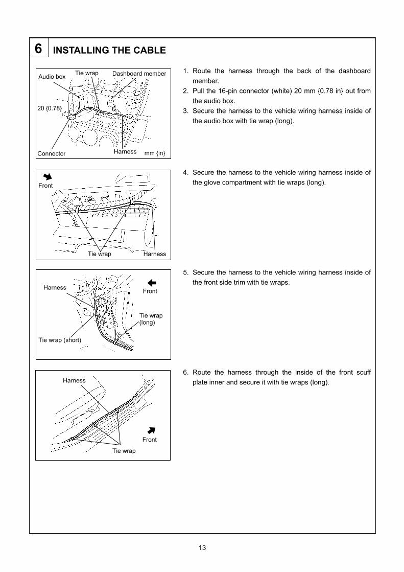
INSTALLING THE CABLE 1. Route the harness through the back of the dashboard
member. 2. Pull the 16-pin connector (white) 20 mm {0.78 in} out from
the audio box. 3. Secure the harness to the vehicle wiring harness inside of
the audio box with tie wrap (long). 4. Secure the harness to the vehicle wiring harness inside of
the glove compartment with tie wraps (long). 5. Secure the harness to the vehicle wiring harness inside of
the front side trim with tie wraps. 6. Route the harness through the inside of the front scuff
plate inner and secure it with tie wraps (long).
6
Harness Tie wrap
Front
20 {0.78}
Connector
Audio box Dashboard member
mm {in} Harness
Tie wrap
Harness
Tie wrap (long)
Front
Tie wrap (short)
Front
Tie wrap
Harness
14
7. Route the harness through the inside of the rear scuff plate
inner and secure it with tie wraps (long). 8. Route the harness through the inside of the trunk side trim
and secure it with tie wraps. 9. Secure the extra harness using a pad protector. 10. Connect the harness connector (black) to the DLP unit. 11. Connect the antenna cable connector to the splitter.
Front
Harness
Tie wrap
Harness
DLP unit
Front
Splitter Antenna cable
Front
Harness
Pad protector Tie wrap (long)
Tie wrap (long)
Tie wrap (short)
Pass through hole
15
12. Route the harness and antenna cable through the inside of
the trunk side trim and secure it with tie wrap (short). 13. Route the harness as shown in the figure and secure it
with pad protector. 14. Route the antenna cable as shown in the figure and secure
it with pad protector halves. 15. Bundle up the antenna cable into a loop using a tie wrap
(short), and secure it to the vehicle panel with pad protector halves.
Tie wrap Harness
Antenna cable
Pad protector Front
DLP unit
Pad protector
Pad protector
Tie wrap
• Be sure to bundle the antenna cable into a loop.CAUTION
16
REINSTALLATION OF VEHICLE PARTS
• Disconnect the negative battery cable and wrap tape around it to insulate
• Install in the reverse order of “4. Part removal”.
• Perform the Inspection indicated on the last page of these installation instructions.
7
• After installing the vehicle parts, check for dirt. Clean any dirty parts. CAUTION
• After completing the installation, refer to the owner’s manual for instructions on how to reset the clock and preset radio stations, and record the trip meter numbers on the check sheet.
Note
• When the negative battery cable is connected during operation, it may cause electric shock or other personal injuries. Disconnect the negative battery cable before removal/installation.
CAUTION
• Disconnecting the battery causes the DSC indicator light to become inoperable. (At this point, the DSC OFF indicator light flashes and the TCS/DSC indicator light is illuminated.)
• To restore the DSC to an operable condition, perform the following procedures: 1. Turn the ignition switch to the ON position. 2. Turn the steering wheel completely to the right and then completely to the left. 3. Verify that the DSC OFF indicator light goes out. 4. Turn the ignition switch off and then turn it to the ON position again. 5. Verify that the TCS/DSC indicator light goes out. If the TCS/DSC or DSC OFF indicator lights do not go out after turning the ignition switch to theON position, consult your Mazda dealer.
• When the battery is disconnected, the windows will not fully open and close automatically. Perform the following procedure to resume operation: 1. Turn the ignition switch to the ON position. 2. Press the switch and fully open the window. 3. Pull up the switch and continue holding for about 2 seconds to fully close the window. 4. If the function does not operate even after the ignition switch is turned off, contact an Authorized
Mazda Dealer.
CAUTION
17
INSPECTION
• Inspect the installed / reinstalled parts for the following items. • Inspection parts differ depending on the vehicle.
Inspection Items (○)
Inspection Parts Clearance/Fit
Scratches/ Dirt/
Harness interference
Installation/ Tightening/
Engagement Operation check
Rear combination light ○ ○ ○ ○ Trunk side trim ○ ○ ○ Trunk end trim ○ ○ ○ Rear seat cushion ○ ○ ○ Trunk box ○ ○ ○ B-pillar lower trim ○ ○ ○ Center panel unit ○ ○ ○ *1 ○ Glove compartment ○ ○ ○ Front side trim ○ ○ ○ Rear scuff plate inner ○ ○ ○ Front scuff plate inner ○ ○ ○
○ : Applicable *1: Refer to the Owner’s Manual and the SATELLITE RADIO instruction manual, and verify that the system
operates correctly. Ex.: Turn the power ON, increase the volume, and press the SAT button. • Direct access channel 184 is a test channel provided by Sirius.
Press the SAT button on the radio, and if properly installed you will receive a signal from the Sirius broadcast.
Note: Sirius broadcasts can only be received in an open area, enclosed spaces such as garages or work buildings block the satellite reception.