58
Geologic Sequestration of Carbon Dioxide Underground Injection Control (UIC) Program Class VI Well Construction Guidance May 2012

Geologic Sequestration of Carbon Dioxide
Underground Injection Control (UIC) Program Class VI Well Construction Guidance
May 2012

Office of Water (4606M) EPA 816-R-11-020 May 2012 http://water.epa.gov/drink/
UIC Program Class VI Well i May 2012 Construction Guidance
Disclaimer
The Class VI injection well classification was established by the Federal Requirements under the Underground Injection Control Program for Carbon Dioxide Geologic Sequestration Wells (75 FR 77230, December 10, 2010), referred to as the Class VI Rule, establishes a new class of injection well (Class VI).
The Safe Drinking Water Act (SDWA) provisions and EPA regulations cited in this document contain legally-binding requirements. In several chapters this guidance document makes recommendations and offers alternatives that go beyond the minimum requirements indicated by the Class VI Rule. This is done to provide information and recommendations that may be helpful for Class VI Program implementation efforts. Such recommendations are prefaced by the words “may” or “should” and are to be considered advisory. They are not required elements of the Class VI Rule. Therefore, this document does not substitute for those provisions or regulations, nor is it a regulation itself, so it does not impose legally-binding requirements on EPA, states, or the regulated community. The recommendations herein may not be applicable to each and every situation.
EPA and state decision makers retain the discretion to adopt approaches on a case-by-case basis that differ from this guidance where appropriate. Any decisions regarding a particular facility will be made based on the applicable statutes and regulations. Mention of trade names or commercial products does not constitute endorsement or recommendation for use. EPA is taking an adaptive rulemaking approach to regulating Class VI injection wells. The Agency will continue to evaluate ongoing research and demonstration projects and gather other relevant information as needed to refine the Rule. Consequently, this guidance may change in the future without public notice.
While EPA has made every effort to ensure the accuracy of the discussion in this document, the obligations of the regulated community are determined by statutes, regulations or other legally binding requirements. In the event of a conflict between the discussion in this document and any statute or regulation, this document would not be controlling.
Note that this document only addresses issues covered by EPA’s authorities under the SDWA. Other EPA authorities, such as Clean Air Act (CAA) requirements to report carbon dioxide injection activities under the Greenhouse Gas Mandatory Reporting Rule (GHG MRR), are not within the scope of this document.

UIC Program Class VI Well ii May 2012 Construction Guidance
Executive Summary
EPA’s Federal Requirements Under the Underground Injection Control Program for Carbon Dioxide Geologic Sequestration Wells, are codified in the US Code of Federal Regulations [40 CFR 146.81 et seq.], referred to as the Class VI Rule. The Class VI Rule establishes a new class of injection well (Class VI) and sets minimum federal technical criteria for Class VI injection wells for the purpose of protecting underground sources of drinking water (USDWs). This guidance is part of a series of technical guidance documents that EPA is developing to support owners or operators of Class VI wells and the UIC Program permitting authorities in the implementation of the Class VI Rule. The Class VI Rule and associated documents are available at http://water.epa.gov/type/groundwater/uic/wells_sequestration.cfm.
This UIC Program Class VI Well Construction Guidance describes the construction and operating requirements unique to Class VI injection wells and provides suggested options for meeting the Class VI Rule requirements for well materials, design, and construction.
Injection well construction is a critical aspect of the Class VI Rule. Proper well construction is necessary to ensure that carbon dioxide is safely injected into and contained within the targeted injection zone for the protection of USDWs. Improper well construction can contribute to a loss of mechanical integrity which potentially may lead to well failure and potential leakage of carbon dioxide from the well into USDWs. A well that has lost mechanical integrity can serve as a conduit for fluid migration out of the injection zone or serve as a conduit for the migration of native formation fluids between USDWs and other permeable zones. Improper well construction may also result in the carbon dioxide not reaching the intended injection zone.
Assessments of appropriate construction materials and design for these new Class VI injection wells are based on the experience of decades of deep injection well construction and operation under the UIC Class I and Class II well programs. This guidance also draws from the latest research being conducted regarding the injection of carbon dioxide for geologic sequestration (GS) and from the materials and technology knowledge that has been developed over many decades by the oil and gas industry to drill and construct production and injection wells in oil and gas fields.
This guidance describes, for Class VI injection well owners or operators, the construction, testing, and operating requirements for an approved Class VI injection well. It includes guidance and recommendations on how to meet these requirements. This document also describes the information that the UIC Program Director will evaluate when reviewing a permit application for a Class VI injection well. There are many resources available on well construction; therefore, this guidance is focused on meeting the requirements of the Class VI Rule for Class VI well construction and operation.
UIC Program Class VI Well iii May 2012 Construction Guidance
Table of Contents Disclaimer ........................................................................................................................................ i Executive Summary ........................................................................................................................ ii Table of Contents ........................................................................................................................... iii List of Figures ..................................................................................................................................v Acronyms and Abbreviations ........................................................................................................ vi Definitions..................................................................................................................................... vii 1 Introduction ..............................................................................................................................1
1.1 The Importance of Well Construction ..................................................................................1 1.2 Purpose .................................................................................................................................2
2 Construction Requirements for Class VI Injection Wells ........................................................4 2.1 Preventing Fluid Movement Outside of Injection Zone .......................................................4
2.1.1 Demonstrating Mechanical Integrity .......................................................................4 2.1.2 Typical Injection Well Components Preventing Fluid Movement ..........................5
2.2 Designing Class VI Wells for Logging and Workovers .......................................................8 2.2.1 Design Considerations .............................................................................................8 2.2.2 Continuous Monitoring of the Annulus ...................................................................9 2.2.3 Deviation Checks ...................................................................................................10 2.2.4 Caliper Logs ...........................................................................................................10
2.3 Well Plan and Design Information to Submit to the UIC Program Director With a Class VI Injection Well Permit Application ................................................................................13
2.4 Designing Class VI Wells for Down-hole Stresses ............................................................13 2.4.1 Types of Stresses....................................................................................................13 2.4.2 Corrosion Considerations.......................................................................................17 2.4.3 Stress and Compatibility Information to Submit to the UIC Program Director
with a Class VI Injection Well Permit Application ..............................................19 2.5 Cementing the Casing of Class VI Wells ...........................................................................20
2.5.1 Different Stage Options for Cementing .................................................................22 2.5.2 Cementing Information to Submit to the UIC Program Director with the Class
VI Injection Well Permit Application ...................................................................24 2.5.3 Cement Compatibility ............................................................................................25 2.5.4 Cement Bond and Variable Density Logs .............................................................27
2.6 Selecting the Tubing and Packer of Class VI Wells ...........................................................29 2.7 Additional Well Construction Information to Submit to the UIC Program Director with
a Class VI Injection Well Permit Application ....................................................................30 2.8 Selecting Surface and Down- Hole Shut-Off Devices for Class VI Wells.........................31
2.8.1 Surface Safety Systems ..........................................................................................31 2.8.2 Down-Hole Devices ...............................................................................................31 2.8.3 Shut-off System Information to Submit to the UIC Program Director with a
Class VI Injection Well Permit Application .........................................................32 3 Considerations for Conversion of Other Well Types to Class VI .........................................33
3.1 Permit Application Submittals ............................................................................................34 3.2 Considerations for Repermitted Wells ...............................................................................35
3.2.1 Material Strength ...................................................................................................35 3.2.2 Material Compatibility ...........................................................................................36
UIC Program Class VI Well iv May 2012 Construction Guidance
3.2.3 Well Design ...........................................................................................................37 3.2.4 Mechanical Integrity ..............................................................................................38
4 Operating Requirements for Class VI Injection Wells ..........................................................40 4.1 Injection Pressure Requirements of Class VI Wells ...........................................................40 4.2 Monitoring of the Annular Space of Class VI Wells ..........................................................41 4.3 Maintaining Mechanical Integrity of Class VI Wells .........................................................41
5 Conclusions ............................................................................................................................42 6 References ..............................................................................................................................44
UIC Program Class VI Well v May 2012 Construction Guidance
List of Figures
Figure 1. Relevant API Specifications and Recommended Practices (RP) for Injection Well Construction ..................................................................................................................... 2
Figure 2. Selected Class VI Injection Well Related Construction References ............................... 3
Figure 3. Schematic of a Class VI Injection Well .......................................................................... 5
Figure 4. Schematic of a Well Packer ............................................................................................ 8
Figure 5. Schematic of a Landing Nipple ....................................................................................... 9
Figure 6. Mechanical Caliper Logging Tool ................................................................................. 12
Figure 7. Stresses on the Well Bore. ............................................................................................. 16
Figure 8. API Well Cement Types ................................................................................................ 17
Figure 9. Schematic of Two-Stage Cementing ............................................................................. 23
Figure 10. Reactions of Carbon Dioxide with Cement ................................................................. 26
Figure 11. Cement Bond Log and Variable Density Log Displays .............................................. 28

UIC Program Class VI Well vi May 2012 Construction Guidance
Acronyms and Abbreviations API American Petroleum Institute C-S-H Calcium Silica Hydrate EOR Enhanced Oil Recovery EGR Enhanced Gas Recovery EPA U.S. Environmental Protection Agency GRE Glass Reinforced Epoxy GS Geologic Sequestration H2O Water MI Mechanical Integrity MIT Mechanical Integrity Test MPa megapascals Pa pascals ppm parts per million RP Recommended Practice SCADA Supervisory Control and Data Acquisition SDWA Safe Drinking Water Act SS Stainless Steel TDS Total Dissolved Solids UIC Underground Injection Control USDW Underground Source of Drinking Water
UIC Program Class VI Well vii May 2012 Construction Guidance
Definitions
Key to definition sources: 1: Class VI Rule Preamble. 2: EPA’s UIC website (http://water.epa.gov/type/groundwater/uic/glossary.cfm). 3: Definition drafted for the purposes of this document. 4: 40 CFR 146.81(d). 5: 40 CFR 144.6(f) and 144.80(f). 6: 40 CFR 144.3.
Annulus means the space between the well casing and the wall of the bore hole; the space between concentric strings of casing; the space between casing and tubing.1
Ballooning refers to the expansion of tubular well materials caused by high pressure.3
Ball valve A valve consisting of a hole drilled through a ball placed in between two seals. The valve is closed when the ball is rotated in the seals so the flow path no longer aligns and is blocked.1
Brine refers to water that has a quantity of salt, especially sodium chloride, dissolved in it. Large quantities of brine are often produced along with oil and gas.2
Buoyancy refers to the upward force on one phase (e.g., a fluid) produced by the surrounding fluid (e.g., a liquid or a gas) in which it is fully or partially immersed, caused by differences in pressure or density.1
Burst strength refers to the pressure, when applied normal to the surface, that will cause a mechanical well component to rupture.3
Carbon dioxide stream means carbon dioxide that has been captured from an emission source (e.g., a power plant), plus incidental associated substances derived from the source materials and the capture process, and any substances added to the stream to enable or improve the injection process. This does not apply to any carbon dioxide stream that meets the definition of a hazardous waste under 40 CFR Part 261.4
Casing refers to the pipe material placed inside a drilled hole to prevent the hole from collapsing. The two types of casing in most injection wells are (1) surface casing, the outermost casing that extends from the surface to the base of the lowermost USDW and (2) long-string casing, which extends from the surface to or through the injection zone.1
Cement refers to the material used to support and seal the well casing to the rock formations exposed in the borehole. Cement also protects the casing from corrosion and prevents movement of injectate up the borehole. The composition of the cement may vary based on the well type and purpose; cement may contain latex, mineral blends, or epoxy. 1
Choke refers to a device using an orifice to regulate flow or pressure.3
UIC Program Class VI Well viii May 2012 Construction Guidance
Choke bean refers to a device in a choke that regulates flow through the choke.3
Class VI wells means wells that are not experimental in nature that are used for geologic sequestration of carbon dioxide beneath the lowermost formation containing a USDW; or, wells used for geologic sequestration of carbon dioxide that have been granted a waiver of the injection depth requirements pursuant to requirements at 40 CFR 146.95; or, wells used for geologic sequestration of carbon dioxide that have received an expansion to the areal extent of an existing Class II enhanced oil recovery or enhanced gas recovery aquifer exemption pursuant to 40 CFR 146.4 and 144.7(d).5
Collapse strength refers to the pressure which will cause a mechanical well component to collapse.3
Confining zone means a geologic formation, group of formations, or part of a formation stratigraphically overlying the injection zone(s) that acts as barrier to fluid movement. For Class VI wells operating under an injection depth waiver, confining zone means a geologic formation, group of formations, or part of a formation stratigraphically overlying and underlying the injection zone.4
Corrosive means having the ability to wear away a material by chemical action. Carbon dioxide mixed with water forms carbonic acid, which can corrode well materials.1
Deviation angle means the angle from which the well bore has deviated from vertical.1
Drilling mud means a heavy suspension used in drilling an ‘‘injection well,’’ introduced down the drill pipe and through the drill bit.6
Enhanced Oil or Gas Recovery (EOR/ EGR) typically means, the process of injecting a fluid (e.g., water, brine, or carbon dioxide) into an oil or gas bearing formation to recover residual oil or natural gas. The injected fluid thins (decreases the viscosity) and/or displaces extractable oil and gas, which is then available for recovery. This is also used for secondary or tertiary recovery.1
Flapper valve means a valve consisting of a hinged flapper that seals the valve orifice. In Class VI wells, flapper valves can engage to shut off the flow of the carbon dioxide when acceptable operating parameters are exceeded.1
Formation or geological formation means a layer of rock that is made up of a certain type of rock or a combination of types.1
Free water refers to water in cement which is not chemically bound to the cement and is free for hydration.
Geologic sequestration means the long-term containment of a gaseous, liquid or supercritical carbon dioxide stream in subsurface geologic formations. This term does not apply to its capture or transport.4
Geologic sequestration project means an injection well or wells used to emplace a carbon dioxide stream beneath the lowermost formation containing a USDW; or, wells used for geologic sequestration of carbon dioxide that have been granted a waiver of the injection depth
UIC Program Class VI Well ix May 2012 Construction Guidance
requirements pursuant to requirements at 40 CFR 146.95; or, wells used for geologic sequestration of carbon dioxide that have received an expansion to the areal extent of an existing Class II enhanced oil recovery or enhanced gas recovery aquifer exemption pursuant to 40 CFR 146.4 and 144.7(d). It includes the subsurface three-dimensional extent of the carbon dioxide plume, associated area of elevated pressure, and displaced fluids, as well as the surface area above that delineated region.4
Injectate means the fluids injected. For the purposes of the Class VI Rule, this is also known as the carbon dioxide stream.1
Injection zone means a geologic formation, group of formations, or part of a formation that is of sufficient areal extent, thickness, porosity, and permeability to receive carbon dioxide through a well or wells associated with a geologic sequestration project. 4
Landing nipple refers to a component made of a short heavy piece of tubular material that has a machined interior to provide a seal and a locking profile. Landing nipples enable the installation of flow control devices such as plugs, chokes, and valves.3
Logging means the measurement of physical properties in or around the well. 3
Mechanical integrity means the absence of significant leakage within the injection tubing, casing, or packer (known as internal mechanical integrity), or outside of the casing (known as external mechanical integrity).1
Mechanical integrity test refers to a test performed on a well to confirm that a well maintains internal and external mechanical integrity. MITs are a means of measuring the adequacy of the construction of an injection well and a way to detect problems within the well system.1
Microseismic monitoring refers to a technique that uses instruments to measure very small movements in the earth.3
Packer means a mechanical device that seals the outside of the tubing to the inside of the long-string casing, isolating an annular space.1
Portland cement refers to a hydraulic cement made by reacting a pulverized calcium silicate hydrate material (C-S-H), which in turn is made by heating limestone and clay in a kiln, with water to create a calcium silicate hydrate and other reaction products. 3
Pozzolan refers to a siliceous or aluminous material that is used as an additive in Portland cement to reduce the calcium hydroxide content and increase the C-S-H content. 3
Radius of curvature refers to the radius of a circle whose arc represents the curvature in a given well bore.3
Reaming refers to widening a borehole using a drilling bit or tool.3
Shoe refers to a rounded collar that is screwed onto the bottom of the casing. It has a check valve in it to prevent backflow of cement slurry. During installation it guides the casing toward the center of the well bore. During cementing cement flows through the shoe and into the space between the casing and formation.3
UIC Program Class VI Well x May 2012 Construction Guidance
Shut-off device refers to a valve coupled with a control device which closes the valve when a set pressure or flow value is exceeded. Shut-off devices in injection wells can automatically shut down injection activities when operating parameters unacceptably diverge from permitted values.2
Supercritical fluid refers to a fluid above its critical temperature (31.1oC for carbon dioxide) and critical pressure (73.8 bar for carbon dioxide).1
Tensile strength refers to the maximum force an element can take in tension before it breaks.3
Tiltmeter refers to an instrument used to measure very small changes in the tilt of an object from the horizontal. 3
Total dissolved solids (TDS) refers to the measurement, usually in mg/L, for the amount of all inorganic and organic substances suspended in liquid as molecules, ions, or granules. For injection operations, TDS typically refers to the saline (i.e., salt) content of water-saturated underground formations.1
Tubing refers to a small-diameter pipe installed inside the casing of a well. Tubing conducts injected fluids from the wellhead at the surface to the injection zone and protects the long-string casing of a well from corrosion or damage by the injected fluids.2
Underground Injection Control Program refers to the program EPA, or an approved state, is authorized to implement under the Safe Drinking Water Act (SDWA) that is responsible for regulating the underground injection of fluids by injection wells. This includes setting the federal minimum requirements for construction, operation, permitting, and closure of underground injection wells.3
Underground Injection Control Program Director refers to the chief administrative officer of any state or tribal agency or EPA Region that has been delegated to operate an approved UIC program.2
Underground Source of Drinking Water means an aquifer or portion of an aquifer that supplies any public water system or that contains a sufficient quantity of ground water to supply a public water system, and currently supplies drinking water for human consumption, or that contains fewer than 10,000 mg/L total dissolved solids and is not an exempted aquifer.1
Well bore refers to the hole that remains throughout a geologic (rock) formation after a well is drilled.3
Wireline refers to a wire or cable that is used to deploy tools and instruments downhole and that transmits data to the surface.3
Workover refers to any maintenance activity performed on a well that involves ceasing injection or production and removing the wellhead.3

UIC Program Class VI Well 1 May 2012 Construction Guidance
1 Introduction
1.1 The Importance of Well Construction
The United States Environmental Protection Agency (EPA) established the Underground Injection Control (UIC) program in the 1980s to protect underground sources of drinking water (USDWs) from contamination by injection well activities. EPA’s Federal Requirements Under the Underground Injection Control (UIC) Program for Carbon Dioxide Geologic Sequestration Wells, codified in the US Code of Federal Regulations [40 CFR 146.81 et seq.], is referred to as the Class VI Rule. The Class VI Rule establishes a new class of underground injection well (Class VI) and sets minimum federal technical criteria for Class VI injection wells for the purpose of protecting USDWs from endangerment. The UIC Program Class VI injection well requirements are designed to protect USDWs and prevent endangerment from carbon dioxide injection and related activities. The requirements will also ensure that the carbon dioxide reaches the intended injection zone and is properly confined.
The materials and techniques for constructing wells in a way that prevents the migration of fluids along the well bore are well documented and have been employed in the construction of many Class II wells regulated under the Safe Drinking Water Act (SDWA). For decades, Class II wells have been constructed and operated for injection of carbon dioxide into mature oil reservoirs to enhance oil production. For these enhanced oil recovery (EOR) operations, thousands of injection wells have been successfully constructed and operated by numerous oil and gas companies in many different oil fields in the United States. In addition, Class I hazardous waste injection has provided experience in the injection and containment of buoyant and corrosive material.
While there are some similarities between carbon dioxide injection in Class VI wells and carbon dioxide injection in Class II wells, there are also some important differences. These differences include higher injection rates for geologic sequestration (GS), as Class VI wells are likely to inject more carbon dioxide into formations than Class II wells, resulting in higher pressures. Higher rates are also of concern because carbon dioxide is less dense than most subsurface fluids and will tend to migrate to the top of the injection zone. Also, Class II wells are known to inject into geologic structures that trap hydrocarbons and thus carbon dioxide, whereas less may be known initially about the geology (e.g., structure and stratigraphy) at GS sites. The time frame of Class VI injection will likely be considerably longer than is typical in Class II wells. Additionally, carbon dioxide has the potential to be corrosive in the presence of water. Proper well construction should address this potential corrosivity and is essential for the protection of USDWs. An improperly constructed well can lead to loss of well integrity that could lead to carbon dioxide or formation fluid leakage from the well bore and into USDWs. Flaws in construction may also allow carbon dioxide to leak from the formation after it has been injected. Finally, since the goal of GS is the long term storage of carbon dioxide, the well integrity must be maintained for the life of the project or it could potentially serve as a conduit for carbon dioxide flow out of the injection zone even after injection has ceased.
The American Petroleum Institute (API) is a professional trade organization for the oil and gas industry. The API develops recommended standards and practices, including practices related to

UIC Program Class VI Well 2 May 2012 Construction Guidance
well construction and operation which are used throughout the industry. These oil and gas well technologies and practices provide a foundation for Class VI well construction technology. In addition, standard practices from Class I injection well construction inform Class VI requirements. Figure 1 lists API reports that provide specifications and recommended best practices applying to well construction. Figure 2 includes several references that provide details on well construction; many are specific to wells injecting carbon dioxide. Complete references for the literature mentioned in Figures 1 and 2 are provided in the Reference Section (Section 6) of this document.
The remainder of this guidance addresses Class VI injection well construction to ensure the prevention of fluid movement, highlights the unique challenges of well construction due to the buoyancy and corrosivity of carbon dioxide or resulting reaction products, and assists potential Class VI injection well owners or operators in complying with the Class VI injection well construction and operation requirements. EPA recommends that the references listed in this guidance, in addition to other appropriate references, be consulted for general details on aspects of typical deep injection well construction.
Relevant API Specifications and Recommended Practices (RPs)
API Specification 5CT – Specification for Casing and Tubing
API RP 5C1 – Recommended Practices for Care and Use of Casing and Tubing
API RP 10B-2 – Recommended Practice for Testing Well Cements
API Specification 10A – Specification on Cements and Materials for Well Cementing
API RP 10D-2 – Recommended Practice for Centralizer Placement and Stop Collar Testing
API Specification 11D1 – Packers and Bridge Plugs
API RP 14B – Recommended Practice 14B, Design, Installation, Repair, and Operation of Subsurface Safety Valve Systems
API RP 14C – Recommended Practice 14C, Recommended Practice for Analysis, Design, Installation and Testing of Basic Surface Safety Systems for Offshore Production Platforms
API Guidance Document HF1 – Hydraulic Fracturing Operations - Well Construction and Integrity Guidelines
Figure 1. Relevant API Specifications and Recommended Practices (RP) for Injection Well Construction
1.2 Purpose
This document is intended as a resource to help familiarize well owners or operators, along with regulators, with the aspects of Class VI well construction that are important for achieving well integrity and preventing leaks into a USDW. It is intended to guide owners or operators on meeting the construction requirements of the Class VI Rule. This is not intended to be a

UIC Program Class VI Well 3 May 2012 Construction Guidance
comprehensive guidance explaining all the details of injection well construction. Injection well construction is a well-known practice and there are many resources available that describe the necessary construction details. This document is intended to be used as a reference that highlights some important considerations for Class VI injection wells in particular, including addressing the buoyancy and corrosivity of carbon dioxide, and to mention other previously published more detailed documents for additional assistance.
Well Construction References
General Construction
Randhol et al., 2007. Ensuring Well Integrity in Connection with CO2 Injection
Lyons and Plisga, 2005. Standard Handbook of Petroleum and Natural Gas Engineering 2nd Edition
Bellarby, 2009. Well Completion Design
Aadnoy, 1996. Modern Well Design
EPA, 1982. Well Construction Practices and Technology
Cementing
Watson, 2009. CO2 Storage: Wellbore Integrity Evaluation and Integrity across the Caprock Sweatman et al., 2009. Effective Zonal Isolation for CO2 Sequestration Wells Nelson and Guillot. 2006. Well Cementing
Materials Compatibility
Meyer, 2007. API Summary of Carbon Dioxide Enhanced Oil Recovery Injection Well Technology
Horizontal Well Issues
Joshi, 1991. Horizontal Well Technology
Cement Evaluation
Duguid and Crow, 2007. CO2 Well Integrity and Wellbore Monitoring
Safety Valves
Garner et al., 2002. At the Ready: Subsurface Safety Valves Sides, 1992. Injection Safety Valve Solutions for CO2 WAG Cycle Wells
Drilling
Medley and Reynolds, 2006. Distinct Variations of Managed Pressure Drilling Exhibit Application Potential
Figure 2. Selected Class VI Injection Well Related Construction References

UIC Program Class VI Well 4 May 2012 Construction Guidance
2 Construction Requirements for Class VI Injection Wells
The Class VI Rule details the requirements for Class VI well construction [40 CFR 146.86(a)]. These are generally performance-based requirements developed to ensure that Class VI injection wells are constructed in a manner that ensures safe underground injection and storage of carbon dioxide and prevents endangerment of USDWs. These requirements address well components that serve to restrict the movement of both injectate and native fluids, address well operability, and ensure that the carbon dioxide will reach the intended injection zone and remain confined.
2.1 Preventing Fluid Movement Outside of Injection Zone
The Class VI Rule requires that the Class VI injection well be constructed to prevent movement of fluids into or between USDWs or other unauthorized zones [40 CFR 146.86(a)(1)]. This requirement is one of the more critical aspects of the UIC program. Most elements of the specific construction requirements of the Class VI Rule are intended to achieve this objective.
2.1.1 Demonstrating Mechanical Integrity
Mechanical integrity is a key concept related to the performance of an injection well, and the prevention of injected fluid movement into or between USDWs or other unauthorized zones [40 CFR 146.88(d) and 146.89]. Mechanical integrity of the well is achieved by ensuring that each of the components of the well are constructed with appropriate materials and are functioning together as intended. Maintaining mechanical integrity helps prevent the well and well bore from becoming conduits for fluid migration out of the injection zone. There are two aspects of mechanical integrity: internal and external.
Internal mechanical integrity is the absence of significant leaks in the casing, tubing, or packer. These well components act as the main barriers preventing contact between the injectate (the injected carbon dioxide stream) and the surrounding geologic formations through which the well has been drilled and constructed. Ensuring that these components are constructed properly with appropriate materials and that they remain intact (e.g., are not compromised and do not fail) when subject to stresses or corrosive (and other) operational conditions may prevent carbon dioxide from moving out of the well bore during injection. The pressure applied during an internal mechanical integrity test should be limited to prevent casing ballooning that could create cement defects.
External mechanical integrity is defined as the absence of significant leakage outside of the casing. Maintaining external mechanical integrity ensures that the injected carbon dioxide, which tends to be more buoyant than native formation fluids, does not migrate upwards from the injection zone after it has been injected; therefore ensuring zonal isolation of the injected carbon dioxide. The main construction component for ensuring external mechanical integrity is the cement between the casing and the borehole wall. Properly emplaced cement should both prevent fluid movement by sealing the annular space between the casing and the formation, and protect the well casing from stress and corrosion. Cementing considerations for Class VI injection wells are discussed later in Section 2.5 of this document.
UIC Program Class VI Well 5 May 2012 Construction Guidance
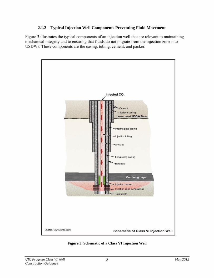
2.1.2 Typical Injection Well Components Preventing Fluid Movement
Figure 3 illustrates the typical components of an injection well that are relevant to maintaining mechanical integrity and to ensuring that fluids do not migrate from the injection zone into USDWs. These components are the casing, tubing, cement, and packer.
Figure 3. Schematic of a Class VI Injection Well

UIC Program Class VI Well 6 May 2012 Construction Guidance
Casing
An injection well typically consists of one or more successively smaller concentric pipes (essentially thick walled pipes within pipes) placed in the well bore. All but the innermost pipe (called the tubing) serve as well casings (see Figure 3). Leaks in the casing can allow fluid to escape into unintended zones or allow fluid movement between zones. The construction materials selected for the casing and the casing design must be appropriate for the fluids and stresses encountered in the site-specific down-hole environment [40 CFR 146.86(b)(1)]. See Section 2.4.2 for additional discussion of appropriate materials for casing. Carbon dioxide in combination with water forms carbonic acid, which is corrosive to many well components. Native fluids can also contain corrosive elements such as brines and hydrogen sulfide. Therefore, the casing must be manufactured of materials that are compatible with fluids with which it might come into contact [40 CFR 146.86(b)(1)].
The surface casing is the largest in diameter. It must extend from the ground surface through the base of the lowermost USDW [40 CFR 146.86(b)(2)]. This casing is emplaced and cemented into the bore hole from the base of the lowermost USDW up to the ground surface, serving to both prevent fluids from entering USDWs and prevent migration of fluids between USDWs and other formations, as the casing isolates the injection fluid. If the lowermost USDW is particularly deep, multiple strings of casing may be used as surface casing. Each string must be cemented to the surface. The smallest diameter casing extends into the injection zone and is referred to as the long-string casing. The long-string casing is routinely perforated in the injection zone to allow fluid to flow out of the injection well and into the injection formation. The spaces between the long-string casing and the surface casing, the long-string casing and the geologic formation, and the surface casing and the geologic formation are called annuli. These annuli are required to be filled with cement in Class VI injection wells, along both the surface and the long-string casing [40 CFR 146.86(b)(3)]. The Class VI Rule requires the long-string casing extend from the ground surface down to the injection zone [40 CFR 146.86(b)(3)].
If the well is very deep, there may be one or more intermediate casings of intermediate diameter between the surface casing and the long-string casing. These casings would be cemented in place as well [40 CFR 146.86(b)(3)]. Cementing considerations for Class VI injection wells are discussed in Section 2.5 of this document.
In some cases, owners or operators may choose to use liners in injection wells. Liners are similar to casing except they are supported by hangers within the casing itself instead of from the surface. Liners can be used as a completion technique or as a remedial solution to contain a leak in the casing. Liners, if used, are well materials and must meet all the requirements that would apply to casing. This includes being cemented to the surface, having sufficient structural strength, and compatibility with the fluids with which they are expected to come into contact [40 CFR 146.86(b)(1) and 146.86(b)(4)]. If an owner or operator plans to use a liner, EPA encourages the owner or operator to communicate the need for the liner and to determine appropriate construction techniques and testing required to ensure mechanical integrity of the liner with the UIC Program Director. However, the use of liners may not always be the best approach due to potential mechanical integrity impacts. Therefore, the owner or operator may want to consider alternatives to liner use.

UIC Program Class VI Well 7 May 2012 Construction Guidance
Tubing
The tubing is a smaller pipe which runs inside the long-string casing from the ground surface down to the injection zone. The injectate moves down the tubing, out through the perforations in the long-string casing, and into the injection zone. The tubing ends at a point just below the packer. The space between the long-string casing and tubing is referred to as the annulus and must be filled with a noncorrosive fluid [40 CFR 146.88(c)].
The tubing forms another barrier between the injected fluid and the long-string casing. Like the casing, it must be designed to withstand the stresses and fluids with which it will come into contact [40 CFR 146.86(c)(1)]. Appropriate materials for tubing are discussed further in Section 2.4.2. The tubing and long-string casing act in concert to form two levels of protection between the carbon dioxide stream and the geologic formations above the injection zone.
Cement
Cement is important for providing structural support of the casing, preventing contact of the casing with corrosive formation fluids, and preventing vertical movement of fluids and gases, including carbon dioxide. Current research indicates that a good cement job is one of the key factors in effective zonal isolation (Watson, 2009; Bachu and Bennion, 2009).
A good cement job begins with the drilling process. The down-hole pressures, fluids, and drilling mud can be managed when drilling so that down-hole conditions are suitable for well construction, cementing, and subsequent injection of carbon dioxide.
Proper placement of the cement for a Class VI injection well is critical, as errors can be difficult to fix later. Failing to cement the casing its entire length, failure of the cement to bond with the casing or formation, not centralizing the casing during cementing, cracking, and alteration of the cement can all allow migration of fluids along the well bore. If carbon dioxide escapes the injection zone through the well bore because of a failed cement job, the well would be out of compliance with the Class VI Rule and required to cease injection [40 CFR 146.88(f)]. It is important to consider, when planning for the cementing of Class VI wells, that carbon dioxide can react with the typical Portland cements commonly used in well construction. Additional discussion of cement reactions as well as alternatives to Portland cement are included in Section 2.5.3.
Packer
A packer is a customary sealing device at the lower end of the tubing which keeps fluid from migrating from the injection zone into the annulus between the long-string casing and tubing (See Figure 4). It must also be made of materials that are compatible with fluids with which it will come into contact [40 CFR 146.86(c)(1)].

UIC Program Class VI Well 8 May 2012 Construction Guidance
Figure 4. Schematic of a Well Packer
2.2 Designing Class VI Wells for Logging and Workovers
Logging involves lowering instruments into the well to perform testing and monitoring of the well or the surrounding geologic formation. Numerous tests and instruments are used to evaluate the formation, determine the reservoir pressure, assess the condition of the well bore, determine the mechanical integrity of the well, and track the movement of the carbon dioxide plume. All of these activities are essential for the proper operation of a Class VI well. In addition, periodic maintenance will need to be performed during the life of an injection well. Maintenance through a well workover involves sealing off the well, removing the wellhead and either removing equipment or lowering maintenance tools into the well. These workovers are essential to maintaining a properly functioning well and can include replacing and repairing tubing, packer, valves and sensors, repairing corroded casing, and remedial cementing. During a workover, tools may need to be lowered into the well, along with valves to seal the lower portions of the well. Logging activities are generally planned; workovers may be planned, but may also arise as result of an emergency. Wells must be designed to accommodate tools necessary for these logging and workover activities [40 CFR 146.86(a)(2)]. Failure to do so can result in the loss of important information or even in the loss of the entire well, resulting in noncompliance with the Class VI Rule that would require cessation of injection if mechanical integrity were lost [40 CFR 146.88(f)].
2.2.1 Design Considerations
Two factors determine if the well is appropriately constructed to allow the necessary equipment for logs and workovers: the diameter and the radius of curvature of the well. To meet the requirements of the Class VI Rule that the well be designed to allow testing [40 CFR 146.86(a)(2)], the diameter of the well must be larger than the largest instrument/tool that may be used in the well. The radius of curvature of the well can limit the length of the instruments/tools that can be used. The casing and radius of curvature of the well should be designed so that any appropriate equipment/tool that may be used in the well will pass without getting stuck. The requirements for testing, monitoring and site characterization of a Class VI injection well are codified in the Class VI Rule and discussed in both the Draft UIC Program Class VI Well Site Characterization Guidance and the Draft UIC Program Class VI Well Testing and Monitoring Guidance. The suggested appropriate equipment sizes can be obtained from the specific equipment manufacturers.
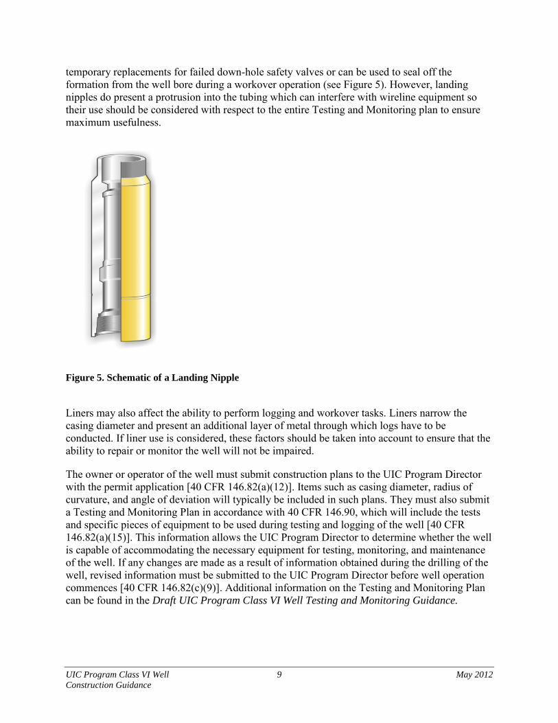
Owners or operators may also want to consider installing landing nipples above the packer. Landing nipples allow for the installation of temporary safety valves that can be used as
UIC Program Class VI Well 9 May 2012 Construction Guidance
temporary replacements for failed down-hole safety valves or can be used to seal off the formation from the well bore during a workover operation (see Figure 5). However, landing nipples do present a protrusion into the tubing which can interfere with wireline equipment so their use should be considered with respect to the entire Testing and Monitoring plan to ensure maximum usefulness.
Figure 5. Schematic of a Landing Nipple
Liners may also affect the ability to perform logging and workover tasks. Liners narrow the casing diameter and present an additional layer of metal through which logs have to be conducted. If liner use is considered, these factors should be taken into account to ensure that the ability to repair or monitor the well will not be impaired.
The owner or operator of the well must submit construction plans to the UIC Program Director with the permit application [40 CFR 146.82(a)(12)]. Items such as casing diameter, radius of curvature, and angle of deviation will typically be included in such plans. They must also submit a Testing and Monitoring Plan in accordance with 40 CFR 146.90, which will include the tests and specific pieces of equipment to be used during testing and logging of the well [40 CFR 146.82(a)(15)]. This information allows the UIC Program Director to determine whether the well is capable of accommodating the necessary equipment for testing, monitoring, and maintenance of the well. If any changes are made as a result of information obtained during the drilling of the well, revised information must be submitted to the UIC Program Director before well operation commences [40 CFR 146.82(c)(9)]. Additional information on the Testing and Monitoring Plan can be found in the Draft UIC Program Class VI Well Testing and Monitoring Guidance.
UIC Program Class VI Well 10 May 2012 Construction Guidance
2.2.2 Continuous Monitoring of the Annulus
The well must be constructed to allow for continuous monitoring of the annular space between the injection tubing and the long-string casing, [40 CFR 146.86(a)(3)]. Continuous monitoring will require a pressure gauge. More details on the monitoring required and how to accomplish it are provided in the Draft UIC Program Class VI Well Testing and Monitoring Guidance.
2.2.3 Deviation Checks
Deviation checks are required during drilling on all holes constructed by drilling a pilot hole that is enlarged by reaming or another method [40 CFR 146.87(a)(1)]. Deviation checks measure the deviation of the borehole from vertical. In many cases, a smaller-diameter pilot hole will be drilled prior to construction of the injection well. In cases where the injection well borehole is constructed by enlarging the pilot hole, the possibility exists for the accidental creation of two ‘divergent’ holes, which may act as vertical avenues for fluid movement. The main purpose of deviation checks are to ensure no divergent holes have been drilled. Deviation checks also aid in determining the path of the well and ensuring it reaches the intended injection zone. In order to adequately test for divergent holes, a deviation check needs to be conducted on the pilot hole prior to enlarging, and the final borehole. Application A deviation check measures the angle of the well and can detect whether the borehole is off of true vertical. The deviation check can be conducted using measurement-while-drilling equipment, or it can be performed by removing the drill and lowering a separate piece of equipment on a wireline. Inclinometers are the simplest logging tools used to perform deviation checks, and consist of a pendulum or other device lowered into the borehole that measures the angle of the well relative to true vertical. Accelerometers are more advanced, and consist of an electronic tool that measures the acceleration due to gravity. A set of three accelerometers mounted on perpendicular axes can give three-dimensional information on the path of the wellbore. More modern equipment also may include magnetometers or gyroscopes, which directly measure borehole depth and direction. In all cases, the three-dimensional path of the well bore is calculated from logging results using mathematical algorithms. Interpretation EPA anticipates that the results of the deviation survey will provide a representation of the three-dimensional path of the pilot hole and the final enlarged borehole. Overlaying the schematics will ensure that the original pilot hole has been completely encompassed by the final borehole, and no divergent holes exist. If divergent holes are identified, the remaining depth of the divergent pilot hole needs to be completely filled with cement, and the cementing records provided to the UIC Program Director for approval prior to injection.
2.2.4 Caliper Logs
The Class VI regulations require that caliper logs be conducted before installation of the surface casing, and before installation of the long-string casing [40 CFR 146.87(a)(2)(i) and 40 CFR

UIC Program Class VI Well 11 May 2012 Construction Guidance
146.87(a)(3)(i)]. The caliper log is a record of the borehole diameter as it varies with depth, and is used to detect washed out zones that may have occurred during borehole drilling. Caliper log results may also indicate the presence of fractures, but caliper logs alone are not an acceptable form of a fracture finder log. Application Mechanical caliper logging tools consist of several detector arms fitted along a central shaft (Figure 6). During measurement, the probe is lowered to the bottom of the borehole, and arms are fully extended until they contact the borehole wall. As the logging tool is pulled upwards the detector arms extend in locations with a large borehole diameter, and retract in locations with a smaller diameter. The arms’ movements are converted to an electrical signal that is transmitted to the surface and recorded (EPA, 1982b). Interpretation The recorded caliper log is a graph of the internal radii measured by each arm as a function of depth. One trace represents the average diameter of the borehole. The caliper log is analyzed to ensure that the borehole diameter is consistent throughout the vertical length of the well, and there has been no collapse or wash-out. The results from the caliper log are used to calculate the amount of cement needed and to identify any potential areas of lost circulation. They may also be used to correct logs that are dependent on the size of the borehole, such as gamma logs. After casing installation, caliper logs may also be used as a form of a casing inspection log to measure the internal radii of the casing, and detect breaks, distortion, or corrosion.

UIC Program Class VI Well 12 May 2012 Construction Guidance
Figure 6. Mechanical Caliper Logging Tool
UIC Program Class VI Well 13 May 2012 Construction Guidance
2.3 Well Plan and Design Information to Submit to the UIC Program Director With a Class VI Injection Well Permit Application
The required project plans, mentioned in Section 2.2 and in more detail in the UIC Program Class VI Well Project Plan Development Guidance, as well as the required construction material and design information discussed in this guidance document, must be submitted to the UIC Program Director as part of the Class VI permit application [40 CFR 146.82(a)(12) and 146.86]. The UIC Program Director should evaluate the information submitted on the proposed injection well and compare that information to the related procedures and equipment proposed for use in the Testing and Monitoring Plan for consistency. The Class VI Rule includes specific construction requirements for components of the well such as the casing, tubing, cement, and packer [40 CFR 146.86(b) and 146.86(c)]. Other Class VI injection well construction requirements address elements of underground injection that are specific to GS, such as the subsurface reaction products like carbonic acid [40 CFR 146.86(b)(5)].
If the casing does not appear to be large enough to accommodate the proposed equipment, the UIC Program Director may require a larger casing or may require revisions to the Testing and Monitoring Plan to direct the use of different tests or equipment so that the appropriate testing devices and monitoring required by the Class VI Rule can be accommodated by the proposed Class VI injection well design.
The UIC Program Director should also evaluate the construction aspects of the casing, tubing, packer, and cement to ensure that they will not allow fluid migration out of the injection zone. The UIC Program Director should review the materials used in these components to ensure their compatibility with the carbon dioxide stream and the formation fluids. The strength of the materials will also be reviewed to ensure their ability to withstand the stresses of the down-hole environment. More details on specific elements that the UIC Program Director may review for the casing, tubing, packer, and cement are found later in this document. The UIC Program Director should review the proposed construction of the annular space between the tubing and long-string casing to ensure that it allows measurement of pressure and other variables. For more details, see the Draft UIC Program Class VI Well Testing and Monitoring Guidance.
2.4 Designing Class VI Wells for Down-hole Stresses
2.4.1 Types of Stresses
The Class VI Rule requires that the well be constructed to withstand anticipated stresses, last the lifetime of the project, and be compatible with fluids with which the materials may be expected to come into contact [40 CFR 146.86(b)(1)]. This requirement applies to the casing and cement. Well materials in the down-hole environment are subject to multiple stresses. Stresses the owner or operator should consider in well design and construction include, but are not limited to:
• Pressure from the injectate;
• Pressure from the formation;
• Tensile stress from the weight of the casing or tubing;
• Compressive stress during installation;

UIC Program Class VI Well 14 May 2012 Construction Guidance
• Cyclic stress from cycling the injection on and off;
• Stress from extreme temperatures; and
• Stresses from temperature changes.
Although not anticipated during normal operations, another source of potential stress could be due to a rapid change in carbon dioxide volume in the event the carbon dioxide being injected undergoes a phase change. For example, this might happen if there was a sudden loss of pressure at the wellhead.
Horizontal and deviated wells can experience additional stresses not experienced by vertical wells (Cernocky and Scholibo, 1995). Additional stresses are caused by the weight of the rock column, especially in weak or unconsolidated formations. In vertical wells, the force from the weight of the rocks is parallel to the well bore and does not impart additional stress on the well. The portion of the casing in the curved portion of the well also experiences additional stress from being curved. Installation through the bend also causes higher friction and torque to be exerted on the casing. Because of the additional stresses on the casing in horizontal wells, thicker casing walls or stronger casing materials may be advantageous.
Extreme temperatures can provide stress on well materials. High temperatures can cause expansion of materials and weaken their strength. If cold fluids are injected they can result in freezing of annular fluids which can apply additional stresses on the well materials.
Cyclic stresses can also be produced by fluctuations in temperatures, for example if the temperature of the fluids injected varies substantially from the reservoir pressure and injection is not continuous. Any of these stresses can cause components to fail and potentially lead to the escape of fluids from the injection zone and a violation of Class VI construction requirements [40 CFR 146.86(a)(1)]. If this occurs, the owner or operator will be required to cease injection [40 CFR 146.88(f)].
The well must be constructed to withstand all the stresses of the down-hole environment [40 CFR 146.86(a)(1)]. Figure 7 presents the different stresses or forces that can be encountered and EPA recommends to be factored into the Class VI injection well design and construction. Many stresses can be predicted and factored into well design, although a safety factor is normally included to account for unanticipated stresses (e.g., a stuck pipe during casing placement, sudden unanticipated pressure changes).
The external stress on the well casing and tubing from the formation, the internal stress on the well casing and tubing from injection, and the force along the well casing and tubing should all be determined. The well components should be designed to withstand the maximum anticipated stress in each direction [40 CFR 146.86(c)(3)(vi) and 146.86(c)(3)(vii)]. EPA understands that a safety factor typically is included in determining the necessary strength of the well materials, and recommends that an appropriate safety factor be agreed upon with the UIC Program Director. The loading from the formation or compressive force is a combination of the formation pressure, which can be measured, and any additional loading from the rock column, on portions of the well that are not perfectly vertical. The force from the rock column can be predicted given knowledge

UIC Program Class VI Well 15 May 2012 Construction Guidance
of the rock column. Further information on determining formation pressure can be found in the Draft UIC Program Class VI Well Site Characterization Guidance.
The internal loading on the well is determined by the injection pressure and/or the pressure on the annulus between the casing and tubing [40 CFR 146.86(c)(3)(iii) and 146.86(c)(3)(iv)]. The injection pressure is a fundamental well design parameter and therefore is known before construction begins. Axial loading is loading along the long dimension of the well boring. If the casing is being suspended from the surface (such as it would be during installation) the axial loading is the weight of the casing below a given point minus any buoyant forces. In the case of stuck pipe, the axial force will be upward and tend to compress the casing instead of pull on it. Mechanical stresses can often be predicted knowing the site characteristics. Many well construction contractors have proprietary software that can calculate the stresses to which a well is subject. EPA expects these programs to be able to calculate the forces in the outward, inward, and axial directions.

UIC Program Class VI Well 16 May 2012 Construction Guidance
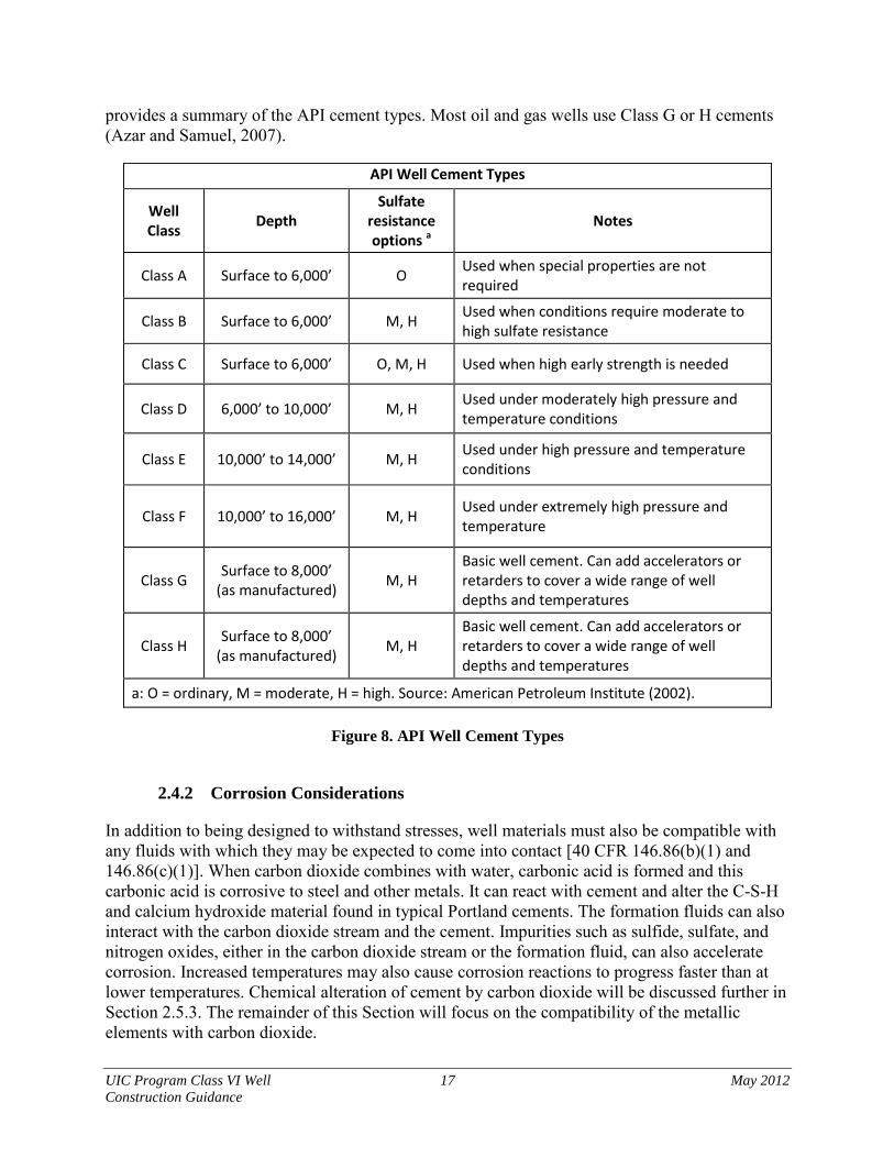
Figure 7. Stresses on the Well Bore. The loading in each of the stress directions should be compared to the strength of the material in that direction. The loadings correspond to the burst, collapse, and tensile strengths of the material [40 CFR 146.83(c)(3)(vii)]. EPA anticipates that the manufacturer of the materials should be able to provide acceptable loading capacity estimates. EPA recommends selecting materials that can resist maximum stresses anticipated in all three directions with a safety factor to account for unanticipated stresses. If stronger casing or tubing is needed, different alloys can be chosen, or thickness can be increased to increase the strength of the well construction materials. Cement strengths can be modified by various additives. API Specification 5CT (see Figure 1) provides tubing and casing specifications that can aid in choosing the appropriate materials. For cements, API specification 10A lists typical cements used in oil and gas wells. The API cements are all Portland based with various additives to alter cure time, strength, and sulfate resistance. Figure 8
UIC Program Class VI Well 17 May 2012 Construction Guidance
provides a summary of the API cement types. Most oil and gas wells use Class G or H cements (Azar and Samuel, 2007).
API Well Cement Types
Well Class Depth
Sulfate resistance options a
Notes
Class A Surface to 6,000’ O Used when special properties are not required
Class B Surface to 6,000’ M, H Used when conditions require moderate to high sulfate resistance
Class C Surface to 6,000’ O, M, H Used when high early strength is needed
Class D 6,000’ to 10,000’ M, H Used under moderately high pressure and temperature conditions
Class E 10,000’ to 14,000’ M, H Used under high pressure and temperature conditions
Class F 10,000’ to 16,000’ M, H Used under extremely high pressure and temperature
Class G Surface to 8,000’ (as manufactured) M, H
Basic well cement. Can add accelerators or retarders to cover a wide range of well depths and temperatures
Class H Surface to 8,000’ (as manufactured) M, H
Basic well cement. Can add accelerators or retarders to cover a wide range of well depths and temperatures
a: O = ordinary, M = moderate, H = high. Source: American Petroleum Institute (2002).
Figure 8. API Well Cement Types
2.4.2 Corrosion Considerations
In addition to being designed to withstand stresses, well materials must also be compatible with any fluids with which they may be expected to come into contact [40 CFR 146.86(b)(1) and 146.86(c)(1)]. When carbon dioxide combines with water, carbonic acid is formed and this carbonic acid is corrosive to steel and other metals. It can react with cement and alter the C-S-H and calcium hydroxide material found in typical Portland cements. The formation fluids can also interact with the carbon dioxide stream and the cement. Impurities such as sulfide, sulfate, and nitrogen oxides, either in the carbon dioxide stream or the formation fluid, can also accelerate corrosion. Increased temperatures may also cause corrosion reactions to progress faster than at lower temperatures. Chemical alteration of cement by carbon dioxide will be discussed further in Section 2.5.3. The remainder of this Section will focus on the compatibility of the metallic elements with carbon dioxide.

UIC Program Class VI Well 18 May 2012 Construction Guidance
It is important to measure the water content of the carbon dioxide injectate as part of the required characterization of the injectate [40 CFR 146.82(a)(7)(iv)]. If the water content of the injectate or stream is higher than 50 ppm, then corrosion-resistant materials are suggested on all components of the injection well that would come into contact with the carbon dioxide stream (Meyer, 2007). For example, standard injection well construction materials (such as carbon steel) have been used successfully in well construction where carbon dioxide streams include water in an amount equal to or less than 50 ppm. However, if the carbon dioxide stream includes an amount of water at greater than 50 ppm, carbon steel will likely undergo corrosion and EPA recommends that in this case the Class VI injection well operator discuss with the UIC Program Director the use of more corrosion resistant well construction materials in order to meet the requirements at 40 CFR 146.86(b)(1) and 40 CFR 146.86(c)(1). These sections of the Class VI Rule require compliance with applicable standards such as ASTM or API standards.
Corrosion testing of the proposed well materials and manufacturer’s corrosion ratings may also be beneficial and should be considered in the selection of well materials. If other circumstances may cause mixing of carbon dioxide with water in contact with well components, then corrosion resistant materials may need to be considered. For example, if water were to be injected into the well before or after carbon dioxide injection, increased corrosion of exposed metal parts could be encountered.
The UIC Program Director should consider these site-specific conditions in evaluating the proposed well construction. Although the carbon dioxide may push formation water away from the injection well, components of the well that are in contact with the formation must also be compatible with formation fluid. Considering effective placement of the cement sheath or selecting corrosion-resistant casing materials designed for the entire project life, pursuant to 40 CFR 146.86(b), should ensure the well maintains integrity.
Typical corrosion resistant materials include 316 stainless steel, fiberglass, or lined carbon steel for casing and tubing. Casing and tubing can be lined with glass reinforced epoxy, plastic, or cement. If lined casing or tubing is used, care is recommended during installation to avoid damaging the lining (Meyer, 2007). Other metal parts such as packers and valves can be nickel plated or made of other high nickel alloys.
EPA recommends that care be taken to comprehensively discuss Class VI injection well design and construction material specifications with the UIC Program Director; such discussions should consider the anticipated operational conditions of the project. The material specifications are recommended to account for not only contact with wet or dry carbon dioxide but also formation fluids, impurities within the carbon dioxide stream, and physical contact between construction materials such as tubing and packer to prevent galvanic corrosion. Galvanic corrosion can be prevented by isolating dissimilar materials using non-conducting elements between the two metals.
Cathodic protection can also be used to protect well elements from corrosion, although the sacrificial anode will require periodic replacement, which could be a disadvantage for providing long term corrosion protection.

UIC Program Class VI Well 19 May 2012 Construction Guidance
2.4.3 Stress and Compatibility Information to Submit to the UIC Program Director with a Class VI Injection Well Permit Application
The following items must be submitted to the UIC Program Director with a Class VI injection well permit application [40 CFR 146.86(b)(1)(i)-(ix)]:
• Depth to the injection zone;
• Injection pressure, external pressure, internal pressure, and axial loading;
• Size and grade of all casing strings (wall thickness, external diameter, nominal weight, length, joint specification, and construction material);
• Corrosiveness of the carbon dioxide stream and formation fluids;
• Down-hole temperatures;
• Lithology of injection and confining zones;
• Type or grade of cement and cement additives;
• Quantity, chemical composition, and temperature of the carbon dioxide stream; and
• Construction plans for the well.
Corrosiveness of the carbon dioxide stream and formation fluids can be determined by measuring the composition of the fluids along with physical properties such as pH, oxidation/reduction potential, and temperature. Alternatively, the results of corrosion testing of well materials with the carbon dioxide stream and/or formation fluids can provide information on corrosiveness. If any of the above information changes because of additional information gained during drilling of the well after the permit application was approved, the revised information must be submitted to the UIC Program Director before carbon dioxide injection operations can begin [40 CFR 146.82(c)(5)]. The UIC Program Director should review the information to determine the adequacy of the construction plans. The materials proposed to be used will be compared to the information about the corrosiveness of the injectate and its chemical composition. EPA expects that the information on the injection depth, temperatures, injection and formation pressures, and loadings will be compared by the UIC Program Director to the materials proposed and the appropriate construction standards to ensure that the materials proposed to be used in constructing the Class VI injection well can last the life of the project.
The UIC Program Director may request additional information from the owner or operator submitting the permit application if it is unclear that the proposed construction materials can withstand the anticipated down-hole environment, based on the collected site characterization data [40 CFR 146.82(a)(21)]. Such additional information requested may include any results of corrosion tests with the proposed construction materials and carbon dioxide stream to be used, stress modeling results, or results of strength tests on the materials to be used. For more details on corrosion testing, see the Draft UIC Program Class VI Well Testing and Monitoring Guidance.
EPA encourages dialogue between the UIC Program Director and the proposed injection well owner or operator on the construction materials selected and proposed, as well as on any

UIC Program Class VI Well 20 May 2012 Construction Guidance
appropriate additional safety factors to use. EPA anticipates that the final decision of the UIC Program Director on the appropriate well construction materials be made after a consultative process.
2.5 Cementing the Casing of Class VI Wells
The Class VI Rule requires that surface casing extend through the base of the lowermost USDW and be cemented to the surface through the use of single or multiple strings of casing and stages of cement [40 CFR 146.86(b)(2)]. A long-string casing must extend at least to the injection zone and be cemented to the surface [40 CFR 146.86(b)(3)]. EPA recommends that the exact depth of the long-string casing be determined in consultation with the UIC Program Director in order to optimize both protection to USDWs and the GS capability of the well. When cement cannot be recirculated to the surface, as demonstrated through the use of logs, it may be acceptable to use staged cementing to achieve cementing to the surface [40 CFR 146.86(b)(4)].
As previously discussed, the surface casing provides stability to the well bore by preventing unconsolidated soils and aggregates from falling into the borehole. It also typically decreases the amount of drilling mud used in the deeper portions of the well. By extending through the base of the lowermost USDW, the surface casing also seals off USDWs and other permeable zones from deeper intervals of the well bore. Thus, it provides an additional barrier to fluid or injectate migration into a USDW if the tubing and long-string casing should fail. Cementing of the long-string casing serves to seal off the well bore and may prevent fluid or injectate leaks through the casing from entering a permeable zone, such as a USDW. If the cement was absent or improperly emplaced, and there was a tubing and casing failure, carbon dioxide could enter a permeable zone and then potentially migrate into USDWs through an annulus, faults, or abandoned wells, which would be a permit violation, and would require cessation of injection [40 CFR 146.88(f)]. Cementing the casing also protects it from exposure to carbonated brine and other corrosive fluids.
Well cementing is a common construction practice performed in the oil and gas drilling industry. Creation of a tight interface between the cement, casing, and the formation is the key to hydraulic isolation. Figure 2 lists some references that describe the cementing process in detail. Additional references are included in Section 6 of this document.
The Class VI Rule requires use of centralizers in the long-string casing [40 CFR 146.86(b)(3)], and in all other cementing processes, centralizers are recommended. Centralizers hold the casing in the center of the well bore during the cementing process. If centralizers are not used, the cement may end up being thinner (or even non-existent) on one side of the well bore, and the thinner portion will possibly be more susceptible to failure. Centralizer placement is especially important for the section of the injection well passing through the confining zone and into the injection interval. Schumacher et al. (1996) found that using centralizers at every joint for 200 feet above and below the production interval of oil wells produced the best results.
The Class VI Rule allows for cementing to be performed in one or more stages [40 CFR 146.86(b)(4)]. However, EPA prefers single stage cementing because it forms a single cement column with no seams and does not require locating the cement top. In single stage cementing, the cement is injected down the well bore through a cement shoe and into the annulus (e.g.,
UIC Program Class VI Well 21 May 2012 Construction Guidance
between the casing and well bore). The cement is circulated until it reaches the surface and is then allowed to set.
Another consideration for owners or operators is that the drilling mud used impacts the quality of the cement job. During well drilling, fluid or mud is circulated through the well bore to lubricate the drill bit and remove rock cuttings generated during drilling. The pressure created by a circulated column of drilling mud also serves to prevent fluids from intruding into the well bore from the formation. If the hydrostatic pressure of the drilling mud is less than the hydrostatic pressure of a formation (i.e., an “under balanced” condition), fluid from the formation may enter the well bore and, in some circumstances, may cause drilling problems and/or create conditions that make well cementing more difficult. In contrast, drilling mud circulating at too high a pressure (an “over balanced” condition) may result in drilling mud flowing from the well into the formation, sometimes clogging formation pores or even fracturing the formation. Fracturing of the confining zone(s) is prohibited by the Class VI Rule [40 CFR 146.88(a)].
Significantly under or over balanced drilling contributes to well conditions that might result in a poor or failed cement job that may result in channels or micro-annuli (very small channels) in the cement that may serve as conduits for fluid migration. Such channels may lead to fluid migration and violation of the Class VI requirements [40 CFR 146.86(a)(1)]. In addition to adjusting the mud density, the fluid pressure may be controlled by altering pumping rates and using closed loop drilling systems.
Proper displacement of the drilling mud from the formation is also important. Mud that is not properly displaced can cause poor bonding of the cement to the formation and lead to channels along the well bore. Drilling mud can be cleaned out using displacement fluids. Special chemical treatments such as acid washes can also remove drilling mud. Another possibility is using metal “scratchers” attached to the casing which is rotated to mechanically clean the formation (Shryock and Smith, 1981).
Additionally, horizontal wells can provide other challenges for cementing. For example, the use of centralizers is especially important in cementing of deviated or horizontal wells. In a horizontal well, gravity will tend to cause the casing to sit at the bottom of the well bore, which can lead to little or no cement along the bottom of the casing, the drilling fluids penetrating deeper into the formation on the bottom of the well bore, greater formation damage, and settling of the cement. Cement settling can lead to a separation of the cement solids and the water which can cause channeling. EPA recommends that centralizer placement in horizontal wells be closer than the placement in vertical wells.
Horizontal wells also take longer to drill, and the chance of formation damage and cement settling tends to increase over time. Underbalanced drilling with horizontal wells is often used to decrease the extent of formation damage by drilling fluids. Using cement that has no free water, as determined by an API free water test, can help prevent settling and channeling of the cement used in horizontal wells (Joshi, 1991). Keeping the drilling fluid turbulent, using special drilling fluids, and maintaining consistent velocities of the fluid around the pipe have also been found to limit solids channeling and result in better horizontal well cementing jobs (Powell et al., 1995; Lockyer et al., 1990; Sabins, 1990).

UIC Program Class VI Well 22 May 2012 Construction Guidance
2.5.1 Different Stage Options for Cementing
In some cases, cementing along the well casing from the injection zone up to the ground surface in a single stage, as discussed in Section 2.5, may not be possible. The pressure exerted by the cement column increases as the height of the column increases. In very deep wells the pressure may become so great that the cement pumps can no longer maintain the pressure, or the pressure from the cement column under construction may fracture weaker formations. In some cases, highly fractured formations or formations with large voids may not allow cement to circulate to the surface, as the cement will flow into the fractures and voids in the formation instead of stacking vertically in a column up to the ground surface. If single stage cementing cannot be successfully performed, multi-staged cementing may be used [40 CFR 146.86(b)(4)]. Multi-staged cementing can be two-stage, three-stage, or continuous two-stage cementing.
Two- Stage Cementing
Two-stage cementing is performed similarly to single stage cementing, except that a cement collar with cement ports is installed at an appropriate point in the well. The cement collar allows cement to be injected into the annulus between the casing and formation at some point in the column under construction other than the bottom of the well. Figure 9 of this guidance document shows a schematic of a two-stage cementing process. EPA recommends that an appropriate point for the cement collar may be the halfway point of the well or just above a fractured zone where the cement circulation might be lost.
To successfully accomplish two-stage cementing, the cement is pushed out of the well bore using a fluid. Two plugs, often referred to as bombs because of their shape, are then dropped. The first plug closes the section of the well below the collar and stops cement from flowing into the lower portion of the well. The second plug (or opening bomb) opens the cement ports in the collar allowing cement to flow into the annulus between the casing and formation through the cement collar. Cement is then circulated down the well bore, out the cement ports, into the annulus between the casing and formation, and up to the ground surface. Once cementing is complete, a third plug is dropped to close the cement ports (Lyons and Plisga, 2005). If the time between the first and second stage is long enough for the cement to begin to set, care should be taken that the first stage is stopped significantly below the cement ports.
Continuous Two-Stage and Three-Stage Cementing
In continuous two-stage cementing, there is no break between the injection of cement between the first and second stages. Continuous two-stage cementing requires less time than regular two-stage cementing, but it requires a more precise knowledge of the cement level to avoid plugging the cement ports. Three-stage cementing is very similar to two-stage cementing, except that two cement collars are used instead of one. The method used will largely be determined by the characteristics of the well bore. If there are two weak formations where circulation is lost or the well is very deep, three-stage cementing may be advantageous.

UIC Program Class VI Well 23 May 2012 Construction Guidance
Figure 9. Schematic of Two-Stage Cementing
UIC Program Class VI Well 24 May 2012 Construction Guidance
Reverse Circulation Cementing
Another option for cementing is called reverse circulation cementing. In this form of cementing, cement is circulated directly down the annulus between the casing and formation. This technique reduces the bottom hole pressure exerted by the cement column because, instead of the cement traveling all the way down the tubing and then up the exterior of the casing, the cement column only extends from the surface to the bottom of the hole. It often requires use of a lighter weight cement and is more difficult to accomplish than standard cementing. There may be some difficulty in reverse cementing associated with ensuring that the cement has reached the bottom of the casing. The location of the cement can be found using a number of logging tools. For more information on logs, see the Draft UIC Program Class VI Well Testing and Monitoring Guidance.
A related procedure that is occasionally used is a “cement top-off.” This technique is used if cement circulation falls short of the surface by a small amount. In this situation, additional cement is sometimes pumped directly into the annulus using a small diameter pipe called a tremie pipe. Ideally, such circumstances can be avoided through proper knowledge of the formations being cemented and the use of proper cementing procedures. If cement falls short of the surface by a small amount, topping off using a tremie pipe may be acceptable. Care should be taken to ensure that cement is distributed all the way around the casing and that a good cement bond is formed. If the cement is topped off using a tremie pipe, this should be indicated on as-built drawings submitted prior to well operation [40 CFR 146.82(c)(5)]. As with other cementing procedures, it is recommended they be discussed with the UIC Program Director so that adequate logging to ensure proper cement integrity can be planned.
In some cases, fractured and highly porous formations may make circulation to the surface impossible. In these cases, the Class VI Rule allows alternative methods of cementing if approved by the UIC Program Director, provided that the owner or operator can demonstrate by using cement logs that evaluate the cement in a radial direction that the cement does not allow fluid movement behind the well bore (e.g., it will still prevent fluid movement up the annulus between the casing and formation) [40 CFR 146.86(b)(4)]. A determination on alternative methods of cementing would be made by the UIC Program Director, and certain recommendations may be that the cement should be continuous through the entire confining layer, at a minimum, and that permeable zones should also be isolated from each other to prevent cross migration of fluids between zones.
2.5.2 Cementing Information to Submit to the UIC Program Director with the Class VI Injection Well Permit Application
With the submittal of a Class VI permit application, the owner or operator must describe the cementing process and the type of cement to be used [40 CFR 146.86(b)(1)(viii)]. If staged cementing is used, EPA recommends indicating the location and timing of each stage. If continuous cementing cannot be achieved, the owner or operator must indicate the logs used to show cementing will prevent fluid flow along the well bore, as discussed above [40 CFR 146.86(b)(4)]. If actual conditions deviate from the proposed plans during construction, the processes used must be submitted prior to operation [40 CFR 146.82(c)(5)]. A cement evaluation log that radially investigates the cement for each casing string must be submitted to the UIC

UIC Program Class VI Well 25 May 2012 Construction Guidance
Program Director upon installation of the casing [40 CFR 146.87(a)(2),(3)]. For more information on the testing, sampling, and logging requirements of the Class VI rule, see the Draft UIC Program Class VI Well Testing and Monitoring Guidance.
The UIC Program Director should review the proposed cementing method to determine if cement can be circulated to the surface. If site characterization data reveals weak formations or formations with significant fractures, the UIC Program Director should check to ensure that these formations have been taken into account. Staged cementing plans will be reviewed to determine if the locations are appropriate and properly take into account weak formations and cement column height. Upon completion, the UIC Program Director should review cement evaluation logs to ensure that cementing was completed to the surface and that channels, cracking, or annuli that could allow fluid movement are not present. If cementing was not continuous, the UIC Program Director should check the cement evaluation logs to ensure that no fluid pathways exist from the injection zone into shallower formations and that no pathways exist for cross-migration of fluids between permeable zones that may endanger USDWs.
2.5.3 Cement Compatibility
As with other well components, the cement and any additives to the cement must be compatible with the carbon dioxide stream and formation fluids [40 CFR 146.86(b)(5)]. Reactions that can occur when carbon dioxide comes into contact with Portland cement are shown in Figure 10. To create the reaction, a certain amount of carbon dioxide migration has to occur along the cement sheath. The most likely migration pathway is the cement interface with casing and formation, which is created by inefficient cement placement. The initial reaction of carbon dioxide with Portland cement, shown in the first cement dissolution reaction, can cause alteration to form calcium carbonate, which is not necessarily harmful to the well, since calcium carbonate can increase the cement strength and decrease permeability.
Further reactions between carbon dioxide and water shown in the remaining reactions, however, can lead to the dissolution of calcium carbonate and leave behind a porous silica gel. These later reactions can lead to a loss of strength and increase cement permeability. Sulfate, which may be present naturally or as an impurity in the carbon dioxide, can also react with cement. In addition, higher temperatures experienced in down-hole environments can increase the rates of alteration of Portland cement (Barlet-Gouedard et al., 2006; Kutchko et al., 2008; Duguid and Scherer, 2009). If the alteration of the chemical composition of the cement progresses far enough, then failure of the cement may occur. Failure of the cement may lead to migration of carbon dioxide out of the injection zone and violation of the Class VI Rule [40 CFR 146.86(a)(1) and 146.88(f)].
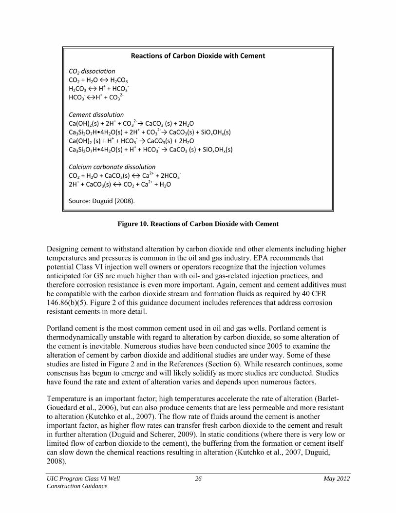
UIC Program Class VI Well 26 May 2012 Construction Guidance
Reactions of Carbon Dioxide with Cement
CO2 dissociation CO2 + H2O ↔ H2CO3 H2CO3 ↔ H+ + HCO3
- HCO3
- ↔H+ + CO32-
Cement dissolution Ca(OH)2(s) + 2H+ + CO3
2-→ CaCO3 (s) + 2H2O Ca3Si2O7H•4H2O(s) + 2H+ + CO3
2-→ CaCO3(s) + SiOxOHx(s) Ca(OH)2 (s) + H+ + HCO3
- → CaCO3(s) + 2H2O Ca3Si2O7H•4H2O(s) + H+ + HCO3
- → CaCO3 (s) + SiOxOHx(s) Calcium carbonate dissolution CO2 + H2O + CaCO3(s) ↔ Ca2+ + 2HCO3
- 2H+ + CaCO3(s) ↔ CO2 + Ca2+ + H2O Source: Duguid (2008).
Figure 10. Reactions of Carbon Dioxide with Cement
Designing cement to withstand alteration by carbon dioxide and other elements including higher temperatures and pressures is common in the oil and gas industry. EPA recommends that potential Class VI injection well owners or operators recognize that the injection volumes anticipated for GS are much higher than with oil- and gas-related injection practices, and therefore corrosion resistance is even more important. Again, cement and cement additives must be compatible with the carbon dioxide stream and formation fluids as required by 40 CFR 146.86(b)(5). Figure 2 of this guidance document includes references that address corrosion resistant cements in more detail.
Portland cement is the most common cement used in oil and gas wells. Portland cement is thermodynamically unstable with regard to alteration by carbon dioxide, so some alteration of the cement is inevitable. Numerous studies have been conducted since 2005 to examine the alteration of cement by carbon dioxide and additional studies are under way. Some of these studies are listed in Figure 2 and in the References (Section 6). While research continues, some consensus has begun to emerge and will likely solidify as more studies are conducted. Studies have found the rate and extent of alteration varies and depends upon numerous factors.
Temperature is an important factor; high temperatures accelerate the rate of alteration (Barlet-Gouedard et al., 2006), but can also produce cements that are less permeable and more resistant to alteration (Kutchko et al., 2007). The flow rate of fluids around the cement is another important factor, as higher flow rates can transfer fresh carbon dioxide to the cement and result in further alteration (Duguid and Scherer, 2009). In static conditions (where there is very low or limited flow of carbon dioxide to the cement), the buffering from the formation or cement itself can slow down the chemical reactions resulting in alteration (Kutchko et al., 2007, Duguid, 2008).
UIC Program Class VI Well 27 May 2012 Construction Guidance
Gaseous or supercritical carbon dioxide may cause less alteration than carbon dioxide dissolved in water, as the supercritical carbon dioxide can result in a surface layer of less permeable calcium carbonate. Field studies examining carbon dioxide alteration of cement in carbon dioxide wells have found evidence of alteration of the cement along the cement-formation interface and reduced permeability and strength of the cement. The permeability and strength reductions, however, were not enough to cause the cement to fail and the permeability value was still smaller than the maximum API recommended value (Carey et al., 2007; Crow et al., 2009).
While all Portland based cements will eventually undergo carbonation by carbon dioxide, the conditions to which the cement will be exposed can be predicted and the well can be designed to better resist those conditions. Additives are available that may facilitate cement resistance to carbon dioxide and other constituents such as sulfate. Some alternatives that can aid in increasing carbon dioxide resistance include:
• Additives that lower the calcium hydroxide content of the cement. While additives such as quartz, silica fume, and fly ash can increase the rate and depth of carbonation penetrating into cement (Sweatman, 2010), these additives also prevent increases in porosity, because they have greater resistance to carbonic acid than the surrounding calcium carbonate; and
• Non-Portland cements which are not as susceptible to attack by carbon dioxide, including phosphate based, pozzolan-lime, gypsum, microfine, expanding cements, calcium aluminate, latex, resin or plastic cements, and sorel cements.
2.5.4 Cement Bond and Variable Density Logs
Cement bond and variable density logs are required after setting and cementing the surface casing and long-string casing [40 CFR 146.87(a)(2)(ii) and 146.87(a)(3)(ii)]. These logs use sonic signals to determine the condition of cement behind the casings and its bonding to the casings. The two cement logs provide complementary information, and are typically run simultaneously. Interpreted together, the logs indicate the presence or absence of cement behind the casing, and the quality of the cement-formation bond. Portions of this section have been adopted from a previous EPA guidance (USEPA, 1982b). Application A single logging tool consisting of a rotating sonic transmitter and two receivers is used to conduct both tests. The receivers are set at different spacings–one is used for the cement bond log, and the other for the variable density log. The transmitter emits a signal that is radiated in all directions while the tool is moved vertically through the borehole. The cement bond log receiver, set three to four feet from the transmitter, detects and measures the amplitude of the first arrival of the reflected sonic signal. When cement is present and firmly bonded to the casing, the attenuation of the signal is large compared to when cement is not present. By recording the amplitude of the sonic signal, it is possible to detect locations where the cement bond may not be adequate and a potential for fluid movement exists.

UIC Program Class VI Well 28 May 2012 Construction Guidance
The variable density log measures the travel time of the transmitted signal and can provide additional information on the quality of the cement. The variable density log receiver is typically set at five feet from the transmitter. The recorded log is a photographic display of the arrival of the sonic signal, and appears as a series of alternating light and dark bands representing variations in positive and negative signals.
Figure 11. Cement Bond Log and Variable Density Log Displays
UIC Program Class VI Well 29 May 2012 Construction Guidance
Interpretation Examples of a cement bond log and variable density log are provided in Figure 11. For the cement bond log, an increase in recorded amplitude of at least 20 percent corresponds to locations of lower signal attenuation and potentially the absence of an adequate cement bond. For the variable density log, the regularity or irregularity of bands indicates the quality of the cement job. For this log, a continuous record of the sonic wave is recorded as the tool is moved vertically through the borehole. The left-most (earliest arriving) bands on the variable density log indicate the condition of the casing-cement bond and lend verification to the cement bond log. Bands further right (later arriving) indicate the condition of the acoustical coupling of the cement and formation. If the cement is well-coupled to both the casing and formation, the right-most bands (last arriving) are indicative of the formation characteristics as the sound energy penetrates deeply. Properly cemented portions of the casing are characterized by weak, almost indistinguishable pipe signal on the left-hand side, and wavy, irregular formation signal on the right-hand side. Cement needs to be present behind all casings and effectively bonded to the casing to provide an adequate seal against fluid movement. If the results of cement bond and variable density logging indicate the absence of cement or an improper seal, action needs to be taken to properly cement the casings prior to commencing injection.
2.6 Selecting the Tubing and Packer of Class VI Wells
The Class VI regulations require that injection occur through tubing. The tubing must be compatible with the carbon dioxide stream [40 CFR 146.86(c)(1)]. Tubing materials are generally similar to the casing well materials listed in Sections 2.1.2 and 2.4.2. The tubing should also be designed with the same types of stressors in mind. The tubing must be designed with burst strength to withstand the injection pressure and the collapse strength to withstand the pressure in the annulus between the tubing and the casing [40 CFR 146.86(b)(1)].
The Class VI regulations also require that injection occur through a packer, set opposite a cemented interval at a depth approved by the UIC Program Director, and compatible with the carbon dioxide stream [40 CFR 146.86(c)(1) and (2)]. Most well construction references include detailed information on tubing and packer. Figure 2 of this guidance document also includes a list of references that discuss the topic in greater depth.
Packers are often made from a hardened rubber such as Buna-N or nitrile rubbers and are nickel plated. Proper materials for packers are important as they are likely to come into contact with corrosive fluids such as carbon dioxide or corrosive brines at some point during the project life. The packer must be compatible with any fluids it may come into contact with [40 CFR 146.86(c)(1)]. Placement of the packer can also be an important consideration, influenced by numerous factors. If the packer is placed above the confining layer, it will allow logs to be run next to the casing through the confining layer without having to pull the tubing. Alternatively, placing the packer close to the perforations may allow instruments used for carbon dioxide plume tracking, such as geophones, to be placed closer to the expected plume. Packer placement can also affect how mechanical integrity tests are conducted and may affect the stress placed on

UIC Program Class VI Well 30 May 2012 Construction Guidance
well components. The owner or operator should consider these factors, in consultation with the UIC Program Director, in order to select the best location for the packer according to project- and site-specific circumstances.
2.7 Additional Well Construction Information to Submit to the UIC Program Director with a Class VI Injection Well Permit Application
The owner or operator must submit the following information concerning the tubing and packer to the UIC Program Director at the time of the permit application [40 CFR 146.86(c)(3)(i)-(vii)]:
• Depth of setting;
• Characteristics of the carbon dioxide stream (chemical content, corrosiveness, temperature, and density) and formation fluids;
• Maximum proposed injection pressure;
• Maximum proposed annular pressure;
• Proposed injection rate (intermittent or continuous) and volume and/or mass of the carbon dioxide stream;
• Size of tubing and casing; and
• Tubing tensile, burst, and collapse strengths.
The UIC Program Director should compare the proposed depth of setting of the packer to all submitted site characterization information to ensure that the packer is set within an approved cemented interval. EPA recommends that the specific location of the packer be determined based on a consideration of site-specific circumstances, such as how the packer will affect cement logging, plume tracking tools, planned mechanical integrity tests, and well component stresses. The UIC Program Director should make sure the interval across which the packer is set is cemented by reviewing cement bond logs. Lack of cement would leave only the casing to serve as a barrier to fluid movement up the well. After reviewing the site characterization data and the tubing and packer depths, the UIC Program Director should either approve the proposed tubing and packer placement or require a revised placement for the tubing and packer.
The proposed injection pressure will be compared to the burst strength of the tubing to ensure sufficient strength. The collapse strength of the tubing will be compared to the proposed maximum annular pressure. If the proposed annular pressure is greater than the collapse pressure of the tubing, the UIC Program Director may either require more competent tubing or allow for a reduction in annular pressure. If a lower annular pressure is allowed, EPA recommends that the owner or operator still maintain a positive pressure on the annulus. There should also be an adequate safety margin between the annular pressure and the tubing collapse pressure and/or the casing burst pressure. The tensile strength of the tubing will be compared to the tensile stress created by the total mass of the tubing to ensure the tubing will not break during installation. The characteristics of the carbon dioxide stream will be compared to the corrosion resistance of the materials proposed for use. This will help ensure that corrosion will not threaten the integrity of the tubing or packer.
UIC Program Class VI Well 31 May 2012 Construction Guidance
If drilling, construction, and logging of the well reveal any changes to information used by the UIC Program Director to determine and specify requirements for tubing and packer , the revised information must be submitted to the UIC Program Director prior to operation of the injection well [40 CFR 146.82(c)(2), 40 CFR 146.82(c)(5)].
2.8 Selecting Surface and Down- Hole Shut-Off Devices for Class VI Wells
2.8.1 Surface Safety Systems
The Class VI Rule requires the installation and use of alarms and automatic surface shut-off systems for onshore injection wells and, at the discretion of the UIC Program Director, down-hole shut off systems may also be required [40 CFR 146.88(e)(2)]. For offshore Class VI injection wells located within state territorial waters, alarms and automatic down-hole shut-off systems are required [40 CFR 146.88(e)(3)]. Although surface shut-off systems are not required for offshore wells, EPA recommends they be installed in addition to the required down-hole systems. Surface safety valves can be beneficial to protect against failures above the downhole valve and to provide a second barrier against loss of well control.
Surface safety systems generally consist of one or more valves and a control system such as a Supervisory Control and Data Acquisition (SCADA) system. Because lengthy hydraulic control lines are not needed to trigger the valve, a wider variety of valves can be employed. The valves are also installed on the wellhead instead of in the casing and can be of larger diameter and provide less of a pressure drop. Any valve used for downhole applications may also be used as a surface valve. In addition, other types of surface-only valves may be used. References listed in Figures 1 and 2 of this guidance document can be consulted for more details on surface safety valves and systems. Surface valves are typically connected to a SCADA or other similar system that monitors variables such as pressure, temperature, and flow. The control system can be set to trigger the valve to close the well if certain alarms are triggered such as a low or high pressure.
2.8.2 Down-Hole Devices
Subsurface or down-hole safety valves have most commonly been used in offshore applications in the oil and gas industry. They have also been used in onshore applications where backflow out of the well would pose a danger such as for acid-gas injection wells or wells operating under high pressure/high temperature conditions. Figure 2 of this guidance document includes several published references that discuss down-hole safety valves in more detail. All down-hole safety valves are designed to be fail-safe and to shut in response to changes in injection pressure or injection rate. The main differences among the different types of valves are in the degree and type of control, and in accessibility. Tubing-retrievable surface-controlled safety valves are the most common down-hole shut-off systems. This type of valve is held open by pressure applied through a hydraulic control line from the surface. When open, the valve does not protrude into the flow. It is set to automatically close if a monitored parameter, such as pressure or flow rate, exceeds pre-set limits. Tubing-retrievable valves are attached to the tubing, as their name implies; therefore, they can be removed for servicing by pulling the tubing. Wireline-retrievable surface-controlled safety valves are also available and can be used to replace failed tubing-retrievable valves or as temporary valves during workovers. For these
UIC Program Class VI Well 32 May 2012 Construction Guidance
surface-controlled valves, the pre-set injection pressure and flow rate values that trigger valve closing can be changed from the surface without pulling the safety valve from the subsurface. There are also a variety of other down-hole safety valves that shut when pre-set pressure or flow limits are exceeded, but the triggering limits cannot be controlled or changed from the surface. These are referred to as direct control valves. Most of these valves use flapper type valves that include check valves, fixed choke velocity valves, variable orifice valves, and pressure differential operated valves. These valves vary in durability, ease of servicing, and in their opening mechanisms. At the point they are located in the injection tubing, surface-controlled or direct control valves (even when fully open) can impede injection flow and cause a drop in pressure. The references provided in Figures 1 and 2 provide more details on the advantages and disadvantages of each specific type of valve.
2.8.3 Shut-off System Information to Submit to the UIC Program Director with a Class VI Injection Well Permit Application
The owner or operator must submit, with the permit application, schematics and other appropriate drawings of the surface and subsurface construction details of the well [40 CFR 146.82(a)(11) and 146.82(a)(12)], these schematics should include the type and location of the safety valve(s) and any landing nipples, if used.
The UIC Program Director should review the type of shut-off system proposed and evaluate its utility and appropriateness for the proposed well. The UIC Program Director should review the closure mechanism to ensure that it will close the valve in the event of a failure of the control equipment. The UIC Program Director should also review the closing parameters and compare them to expected conditions to ensure they are adequate and will not allow fluid to migrate out of the injection zone. Information the UIC Program Director may consider in making this determination include formation pressure, proposed injection pressure, and the presence of any potentially toxic substances in the injection stream or the formation (e.g., hydrogen sulfide, methane).
If the shut-off system (e.g., at the surface, or down-hole) is triggered at any time during project operation, the owner or operator must investigate as expeditiously as possible the cause of the valve triggering [40 CFR 146.88(f)]. If the well has lost mechanical integrity the owner or operator must cease injection immediately, notify the UIC Program Director within 24 hours, determine the cause of the failure, make plans to repair the well, and take all reasonable steps to determine if carbon dioxide has escaped the injection zone [40 CFR 146.88(f)(1)-(f)(4)]. Such steps may include monitoring for carbon dioxide at the surface or in zones above the confining layer using the methods described in the Draft UIC Program Class VI Well Testing and Monitoring Guidance. Once the well repair/workover schedule is known, the UIC Program Director should be notified of the repairs 30 days in advance [40 CFR 146.91(b)(2)]. The owner or operator must restore mechanical integrity to the well and demonstrate this to the UIC Program Director [40 CFR 146.88(f)(4)]. A planned date for when injection is expected to resume should also be given to the UIC Program Director along with the well repair schedule [40 CFR 146.88(f)(5)].
UIC Program Class VI Well 33 May 2012 Construction Guidance
1 40 CFR 146.86(a) General. The owner or operator must ensure that all Class VI wells are constructed and completed to (1) Prevent the movement of fluids into or between USDWs or into any unauthorized zones; (2) Permit the use of appropriate testing devices and workover tools; and (3) Permit continuous monitoring of the annulus space between the injection tubing and long string casing.
3 Considerations for Conversion of Other Well Types to Class VI
The considerations discussed to this point focused on construction of new Class VI wells. However, the Class VI Rule allows for the repermitting of an existing well as a Class VI well, provided the owner or operator can demonstrate to the UIC Program Director that the well under consideration was engineered and constructed to meet the requirements of 40 CFR 146.86(a)1 and ensure protection of USDWs, in lieu of requirements at 40 CFR 146.86(b) and 146.87(a). This section presents considerations for owners or operators and UIC Program Directors where repermitting of an existing well as a Class VI well is under consideration. It includes information owners or operators should submit to the UIC Program Director to demonstrate that a converted well will be suitable for GS and ensure USDW protection. Wells that are converted to Class VI do not need to meet all of the logging and pre-/post-construction requirements that apply to newly constructed Class VI wells, specifically requirements that focus on pre-construction logging and cementing at 40 CFR 146.86(b) and 146.87(a). However, it may be appropriate to conduct some of the tests specified in these requirements (e.g., cement bond logs) prior to or during permitting to demonstrate well suitability. This section provides information about the manner in which an owner or operator may demonstrate that an existing well is appropriate for Class VI injection for GS and clarifies the information that a UIC Program Director will review prior to approving a well for repermitting as a Class VI well, while addressing the intent of the requirements at 40 CFR 146.86(b) and 146.87(a). EPA recommends that this section of the guidance be read in concert with Sections 1 and 2 of this document, because much of the well construction information in Sections 1 and 2, as well as the requirements at 40 CFR 146.82 through 146.85 and 40 CFR 146.89 through 146.95, remain applicable to owners or operators applying to repermit a well for Class VI injection. Wells that might be converted to Class VI wells include Class I wells, Class II wells, and Class V experimental technology wells, monitoring wells, and stratigraphic test wells. For additional information on transitioning Class II wells to Class VI, including determining the point at which repermitting as a Class VI well is necessary, see the Draft Underground Injection Control Program Guidance on Transitioning Class II Wells to Class VI. If the UIC Program Director evaluates well construction information submitted for repermitting of an existing well and determines that USDW protection cannot be ensured for the duration of a Class VI project, a Class VI permit may be denied and an owner or operator may need to construct a new Class VI well or identify a different well for repermitting as a Class VI well.
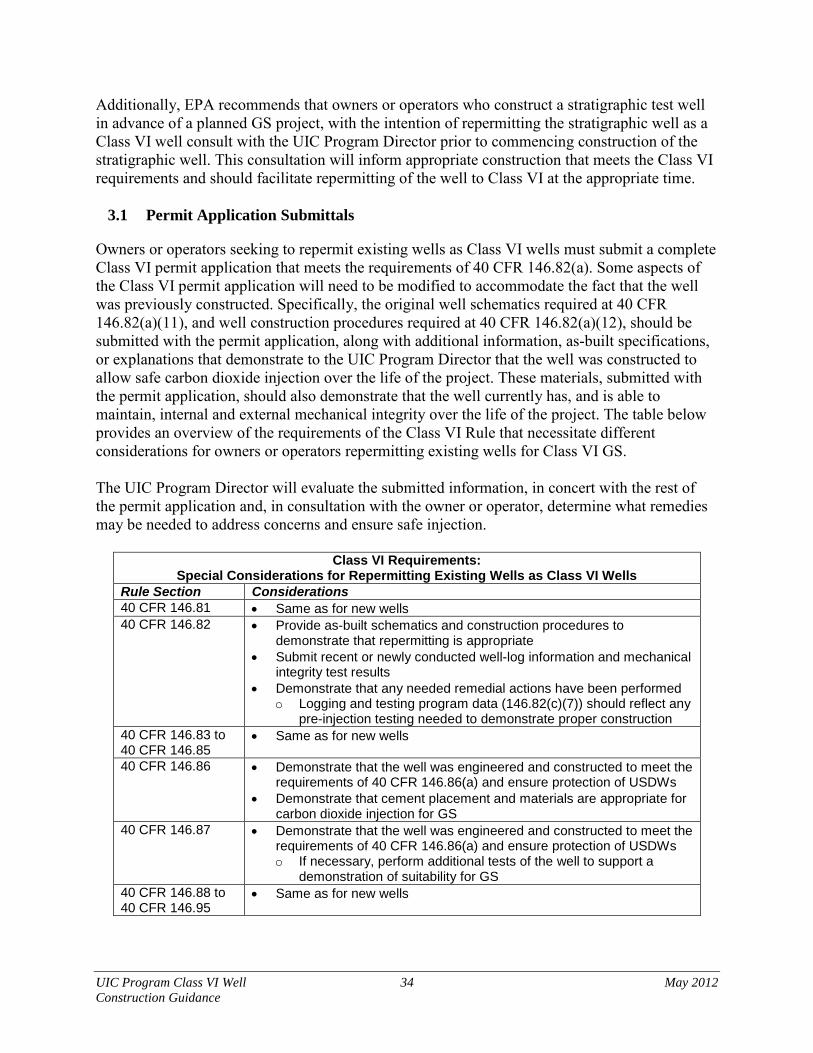
UIC Program Class VI Well 34 May 2012 Construction Guidance
Additionally, EPA recommends that owners or operators who construct a stratigraphic test well in advance of a planned GS project, with the intention of repermitting the stratigraphic well as a Class VI well consult with the UIC Program Director prior to commencing construction of the stratigraphic well. This consultation will inform appropriate construction that meets the Class VI requirements and should facilitate repermitting of the well to Class VI at the appropriate time.
3.1 Permit Application Submittals
Owners or operators seeking to repermit existing wells as Class VI wells must submit a complete Class VI permit application that meets the requirements of 40 CFR 146.82(a). Some aspects of the Class VI permit application will need to be modified to accommodate the fact that the well was previously constructed. Specifically, the original well schematics required at 40 CFR 146.82(a)(11), and well construction procedures required at 40 CFR 146.82(a)(12), should be submitted with the permit application, along with additional information, as-built specifications, or explanations that demonstrate to the UIC Program Director that the well was constructed to allow safe carbon dioxide injection over the life of the project. These materials, submitted with the permit application, should also demonstrate that the well currently has, and is able to maintain, internal and external mechanical integrity over the life of the project. The table below provides an overview of the requirements of the Class VI Rule that necessitate different considerations for owners or operators repermitting existing wells for Class VI GS. The UIC Program Director will evaluate the submitted information, in concert with the rest of the permit application and, in consultation with the owner or operator, determine what remedies may be needed to address concerns and ensure safe injection.
Class VI Requirements: Special Considerations for Repermitting Existing Wells as Class VI Wells
Rule Section Considerations 40 CFR 146.81 • Same as for new wells 40 CFR 146.82 • Provide as-built schematics and construction procedures to
demonstrate that repermitting is appropriate • Submit recent or newly conducted well-log information and mechanical
integrity test results • Demonstrate that any needed remedial actions have been performed
o Logging and testing program data (146.82(c)(7)) should reflect any pre-injection testing needed to demonstrate proper construction
40 CFR 146.83 to 40 CFR 146.85
• Same as for new wells
40 CFR 146.86 • Demonstrate that the well was engineered and constructed to meet the requirements of 40 CFR 146.86(a) and ensure protection of USDWs
• Demonstrate that cement placement and materials are appropriate for carbon dioxide injection for GS
40 CFR 146.87 • Demonstrate that the well was engineered and constructed to meet the requirements of 40 CFR 146.86(a) and ensure protection of USDWs o If necessary, perform additional tests of the well to support a
demonstration of suitability for GS 40 CFR 146.88 to 40 CFR 146.95
• Same as for new wells

UIC Program Class VI Well 35 May 2012 Construction Guidance
Similarly, information submitted prior to authorizing injection, per 40 CFR 146.82(c), will need to be modified to demonstrate that injection can be safely conducted. This should include the results of any remediation performed to address the considerations described in the sections below.
3.2 Considerations for Repermitted Wells
An owner or operator should consider well material strength, material compatibility with carbon dioxide and formation fluids, injection well design, and mechanical integrity when contemplating repermitting a well for Class VI injection. The sections below present: 1) considerations for owners or operators to facilitate a demonstration that an existing well is appropriate for Class VI injection for GS (including potential remedies to address deficiencies) and 2) information that should be submitted to the UIC Program Director to support a determination that repermitting is appropriate.
3.2.1 Material Strength
Injection and formation pressures at GS projects are anticipated to be greater than those encountered in Class I or Class II wells, and will also likely be higher than pressures in monitoring or stratigraphic test wells. Where an owner or operator is seeking to repermit an existing well as a Class VI well, the owner or operator must evaluate and consider these pressures prior to submitting an application for repermitting. The owner or operator should review both the design specifications of the well and its current condition in order to evaluate the well’s integrity to withstand pressures anticipated at the Class VI operation. Considering material strength addresses the purpose of the requirements at 40 CFR 146.86(b)(1), which require that the casing and cementing program be designed to prevent the movement of fluids into or between USDWs through the use of materials of sufficient structural strength. More information on design specifications for strength is found in Section 2.4 of this guidance.
Considerations for the Owner or Operator
An owner or operator converting a well must consider whether the original design of the well is appropriate for GS. Ideally, construction records and schematics detailing the casing type and cement placement in the well will be available. If original design information or schematics are not available, pressure testing records may reveal some information on the strength of the casing. The burst and collapse pressures of the existing casing and tubing should be compared to the proposed injection pressures. If the burst pressure of the casing is lower than or close to the injection pressure, the casing may need to be drilled out and replaced or the well may not be suitable for conversion.
While the design strength of the well casing is important, casing can degrade over time due to corrosion and other stresses. Therefore, assessing the current casing condition is important. To assess the current condition of the casing, an owner or operator should conduct an internal mechanical integrity test that meets the requirements for testing new wells at 40 CFR 146.87(a)(4) or submit results of a recent internal mechanical integrity test. Casing evaluation tools such as caliper logs and casing inspection logs may also provide useful information. If tests reveal casing degradation, the owner or operator, in consultation with the UIC Program Director,

UIC Program Class VI Well 36 May 2012 Construction Guidance
should consider the long-term viability of the well and may consider either drilling out and replacing the casing, using a liner, or finding an alternative well. Where internal mechanical integrity cannot be demonstrated, a well should not be further considered for repermitting as a Class VI well.
Information to Submit to the UIC Program Director
The UIC Program Director will evaluate whether the injection well casing is of sufficient strength to withstand the planned injection pressures at a Class VI well. An owner or operator should submit all available design information on the original well construction to support this review and may wish to refer to 40 CFR 146.86(b) for information on the data the Director will evaluate when assessing material strength. In addition, a recent pressure test at a pressure at least equal to the proposed injection pressure can demonstrate the adequacy of the well design. The UIC Program Director may also request other evaluation tests, such as caliper logs, casing inspection videos, or tracer logs. For additional information on well material strength and compliance with requirements at 40 CFR 146.86(a) and (c), see Sections 2.4 and 2.6 of this document.
3.2.2 Material Compatibility
Another unique aspect of the Class VI Rule is an assessment of well material compatibility with the carbon dioxide stream and formation fluids, discussed in Section 2.4.2. Compatibility is necessary to ensure that well materials will retain integrity throughout the life of the Class VI project.
Considerations for the Owner or Operator
To support an evaluation of the compatibility of well materials, the owner or operator must first characterize the carbon dioxide stream [40 CFR 146.82(a)(7)(iv)]. Carbon dioxide concentration and water content are two key parameters to evaluate. Impurities including sulfate, sulfide, and nitrates, should also be examined. Additionally, an analysis of formation fluids in the injection zone for these parameters and pH, as required at 40 CFR 146.82(a)(8) and 146.87(c), will inform a determination of material compatibility.
The casing, tubing, and cement materials should be evaluated based on knowledge of the anticipated composition of the carbon dioxide stream, formation fluids, the water content of the carbon dioxide stream, and the potential for reactions between the well materials and the injectate and formation fluids. Corrosive combinations such as wet carbon dioxide, hydrogen sulfide, or low pH formation fluids may necessitate a well with more corrosion-resistant well materials such as stainless steel or other advanced well materials and corrosion resistant cements. High concentrations of sulfate may also require special cements. Wells that were constructed of corrosion-resistant materials (e.g., 316 stainless steel) or materials that meet ASTM/API standards are likely to be good candidates for conversion to Class VI.
If the compatibility of the materials with the carbon dioxide stream remains in question, corrosion tests using the carbon dioxide stream and well materials may help determine compatibility. For information about these tests, see the Draft UIC Program Class VI Well Testing and Monitoring Guidance (Section 3.4). If the casing materials are not compatible with

UIC Program Class VI Well 37 May 2012 Construction Guidance
the carbon dioxide stream, the casing may need to be replaced or a liner inserted. If the cement is not compatible, the well may not be suitable for repermitting.
Information to Submit to the UIC Program Director
The owner or operator should provide the UIC Program Director with any original construction specifications or schematics for the well, including casing material and thickness and the type(s) of cement. Analysis of both the injection stream, pursuant to requirements at 40 CFR 146.87(c), and any formation fluids, submitted pursuant to 40 CFR 146.82(a)(7)(iv), will also be necessary to support an assessment of the adequacy of the well materials for carbon dioxide injection for GS. If there are questions regarding the adequacy of materials, corrosion testing results and an indication of any well construction materials that meet or exceed relevant ASTM/API standards may inform a UIC Program Director’s decisions on repermitting.
EPA recommends that the owner or operator and UIC Program Director discuss the well design and construction materials used, particularly in the context of the anticipated operational conditions of the project after repermitting. The material specifications should account for not only contact with wet or dry carbon dioxide but also formation fluids, impurities within the carbon dioxide stream, and physical contact between construction materials such as the tubing and packer to prevent galvanic corrosion. For additional information on well material compatibility see Sections 2.4 through 2.6 of this document.
3.2.3 Well Design
An additional consideration for repermitting existing wells as Class VI wells is well design and cement placement. While Class VI wells must be cemented to the surface, there is some flexibility afforded owners or operators of wells applying to repermit existing wells as Class VI wells. Specifically, wells converting to Class VI may not need to meet the requirement that their long-string casing be cemented to the surface if the owner or operator can demonstrate, to the UIC Program Director’s approval, that there is proper zonal isolation. However, in all cases, repermitting is contingent upon a demonstration that the well meets the requirements at 40 CFR 146.86(a) to prevent the movement of fluids into or between USDWs or into any unauthorized zones.
Considerations for the Owner or Operator
To demonstrate zonal isolation, an owner or operator must demonstrate, at a minimum, that the surface casing has intact cement from the bottom of the lowermost USDW to the surface. Additionally, the long-string casing must be cemented from the production zone into the confining layer. The well should also be cemented across any permeable layers such as oil or gas bearing zones and high TDS aquifers.
Temperature or cement logs performed at the time of original well construction may be helpful in identifying the areas of the well that are cemented. Original well logs or cores may also be necessary to identify permeable zones. If these records are not available, a new set of logs may be necessary and requested by the UIC Program Director. A new cement log evaluating the cement in the radial direction will not only show the location of the cement but also evaluate its integrity. See Section 2.2 for information on performing these logs.

UIC Program Class VI Well 38 May 2012 Construction Guidance
If cement is not present or is inadequate in permeable areas, drilling out the well and re-cementing may be necessary; alternatively, an owner or operator may determine that the well is not suitable for conversion.
Information to Submit to the UIC Program Director
The owner or operator should provide the UIC Program Director with stratigraphic records and well logs that identify where the cement is within the well and its placement relative to any permeable zones. The owner or operator should also demonstrate that all permeable zones have been cemented, and that the surface casing extends below the lowermost USDW and is cemented to the surface. For additional information on well design and cementing requirements for new wells, which may inform data submittals, see Section 2.5 of this guidance and the requirements at 40 CFR 146.86(b).
3.2.4 Mechanical Integrity
Ensuring that a well can pass periodic mechanical integrity testing, allow continuous monitoring, and maintain mechanical integrity throughout its life are key requirements for any well conversion. An owner or operator will need to demonstrate to the UIC Program Director that a well under consideration for repermitting as a Class VI well was designed to maintain both internal and external mechanical integrity, has mechanical integrity at the time of repermitting, and is likely to maintain integrity under the proposed operating conditions throughout the planned life of the GS project. If a well is repermitted as a Class VI well, an owner or operator must continuously monitor the well for internal mechanical integrity [40 CFR 146.89(b)] and conduct external mechanical integrity tests at least once every year [40 CFR 146.89(c)].
Considerations for the Owner or Operator
Maintaining internal mechanical integrity of the well to be converted will ensure delivery of the carbon dioxide to the injection zone and prevent it from leaking into surrounding formations. A pressure test at or above the proposed injection pressure is the most straightforward way to determine if the well has maintained internal mechanical integrity. An owner or operator may also run a casing inspection log and tracer surveys to complement the pressure test and demonstrate internal mechanical integrity. External mechanical integrity ensures that carbon dioxide in the injection zone will not migrate, through channels in the cement, up the well bore to other permeable formations and that fluids cannot move between formations. A cement bond log evaluating the cement radially may help identify any potential channels in the existing cement, while tracer logs, temperature logs, and noise logs should be used to supplement information collected through the cement bond log. See Section 4.3 of this guidance, and the Draft UIC Program Class VI Well Testing and Monitoring Guidance for additional information on demonstration of mechanical integrity for Class VI wells.
UIC Program Class VI Well 39 May 2012 Construction Guidance
Information to Submit to the UIC Program Director
An owner or operator should submit any mechanical integrity tests performed on the well to inform repermitting decisions. While past tests will be useful, recent tests are necessary to ensure that the well currently has mechanical integrity, is capable of accepting carbon dioxide at planned injection rates and volumes, and will maintain mechanical integrity over the planned duration of the proposed Class VI project. If integrity tests reveal leaks in the tubular materials, flaws in the cement, or issues that cannot be easily resolved, the UIC Program Director, in consultation with the owner or operator, may determine that a well is not suitable for carbon dioxide injection for repermitting.
UIC Program Class VI Well 40 May 2012 Construction Guidance
4 Operating Requirements for Class VI Injection Wells
The daily operations of a Class VI injection well are important to maintaining the integrity of the well and ensuring the safe sequestration of carbon dioxide. Class VI operating requirements [40 CFR 146.88] include requirements for operating pressures, mechanical integrity, and automatic shut-off systems (discussed in Section 2.8).
4.1 Injection Pressure Requirements of Class VI Wells
The Class VI Rule requires that the injection pressure not exceed 90 percent of the injection zone fracture pressure except during stimulation [40 CFR 146.88(a)]. All stimulation programs must be approved by the UIC Program Director as part of the permit application [40 CFR 146.82(a)(9)].The Class VI Rule prohibits injection between the outermost casing and the well bore [40 CFR 146.88(b)].
Maintaining the injection pressure below 90 percent of the injection zone fracture pressure is a conservative requirement that prevents the injection zone from being fractured and diminishes the likelihood of fracturing the confining zone which could result in fluid movement out of the injection zone. In some cases, a well stimulation program may be necessary to achieve the desired injectivity of the Class VI injection well. Stimulation usually occurs during completion of the well and may also be conducted if injectivity decreases over the course of the injection project.
Some stimulation methods can induce and propagate fractures. If stimulation is to be performed, a plan for the stimulation procedure must be submitted to the UIC Program Director with the other required Class VI permit approval application information [40 CFR 146.82(a)(9)]. If stimulation is to be performed, other than for formation testing conducted under 40 CFR 146.82, the UIC Program Director must be notified at least 30 days before the operation is performed [40 CFR 146.91(d)(2)]. In either case, the proposed stimulation method must demonstrate that it will not fracture the confining zone or otherwise allow injection or formation fluids to endanger USDWs [40 CFR 146.88(a)]. This can be accomplished by modeling pressures and showing that the fracture pressure of the confining zone is never exceeded.
The modeled pressures can be confirmed using technologies such as tiltmeters and microseismic monitoring to monitor and refine the model; however, these technologies are still experimental and may not be applicable in all circumstances. If additional chemicals are to be used in stimulation it should be shown that they will not react with the confining layer. Information on calculating the fracture pressure of a formation can be found in the Draft UIC Program Class VI Well Site Characterization Guidance. The API Guidance Document RF1 – Hydraulic Fracturing Operations – Well Construction and Integrity Guidelines also contains information on ways to perform stimulation without fracturing the confining layer. Additionally, the Draft UIC Program Class VI Well Testing and Monitoring Guidance provides additional information on how to monitor injection pressure.
Injection between the casing and the formation is not allowed [40 CFR 146.88(b)], as it would provide no barrier between the carbon dioxide and the formation. The Class VI Rule requires the space between the casing and the formation to be cemented [40 CFR 146.86(b)(2) and

UIC Program Class VI Well 41 May 2012 Construction Guidance
146.86(b)(3)]. More information on cementing requirements is available in Section 2.5 of this guidance and in the documents referenced in Figures 1 and 2 of this guidance document.
4.2 Monitoring of the Annular Space of Class VI Wells
The Class VI Rule requires that the annulus be filled with a non-corrosive fluid and that the annular pressure between the tubing and the casing be maintained at a pressure higher than the injection pressure, unless the UIC Program Director determines that this requirement might harm the integrity of the well or endanger USDWs [40 CFR 146.88(c)]. This requirement provides a continuous check on the mechanical integrity of the well. If holes or fractures develop either in the casing, tubing, or packer, the pressure and fluid volume in the annulus will begin to change. In addition, if the pressure in the annulus is higher than the injection pressure, any leak in the tubing will not result in fluid escaping. Instead fluid from the annulus will flow into the tubing.
Using a non-corrosive fluid in the annular space prevents corrosion of the tubing or casing by the annular fluid. If the owner or operator is concerned that an annular pressure higher than the injection pressure will damage the well or endanger USDWs, EPA recommends that they consult with the UIC Program Director to find an applicable solution that will both safeguard USDWs and protect the well. Options may include a more competent casing or operating at a lower, but still positive, annular pressure.
The Draft UIC Program Class VI Well Testing and Monitoring Guidance addresses the subject of monitoring the annular pressure in more detail.
4.3 Maintaining Mechanical Integrity of Class VI Wells
The Class VI Rule also requires that the owner or operator maintain the mechanical integrity of the well [40 CFR 146.88(d)]. Maintaining mechanical integrity ensures that no carbon dioxide can leak and cause endangerment of USDWs. In addition to continuous monitoring for mechanical integrity, mechanical integrity is also verified by periodically conducting mechanical integrity tests (MITs) [40 CFR 146.89(c),(d),(e), and (g)]. See Section 2.1.1 of this guidance document and the Draft UIC Program Class VI Well Testing and Monitoring Guidance for more details on how to perform MITs on Class VI injection wells. The installation and use of continuous recording devices to monitor various pressures and volumes, as well as injection rates is also required [40 CFR 146.88(e)(1)]. Designing for continuous monitoring is discussed in Section 2.2.2 of this document, and the methods and technologies available for this monitoring are discussed in the Draft UIC Program Class VI Well Testing and Monitoring Guidance.
As noted, the requirements for shut-off devices [40 CFR 146.88(e)(2) and 146.88(e)(3)] are discussed in Section 2.8.

UIC Program Class VI Well 42 May 2012 Construction Guidance
5 Conclusions
Class VI injection well construction is a critical factor in meeting the requirement to prevent fluid migration into or between USDWs [40 CFR 146.86(a)(1)]. The construction requirements of the Class VI Rule describe the detailed construction information to be submitted to the UIC Program Director with a Class VI injection well permit application. The main components of the injection well are the casing, cement, tubing, and packer.
• All components of Class VI wells must be constructed to withstand the stressors of the down-hole environment and be compatible with the carbon dioxide stream and any other fluids with which they might come into contact.
• The surface casing must extend through the base of the lowermost USDW through the use of a single or multiple casing strings and be cemented to the surface [40 CFR 146.86(b)(2)].
• The long-string casing must extend to the injection zone and be cemented to the surface [40 CFR 146.86(b)(3)].
• The casing must be designed to allow continuous monitoring of the annular space between the casing and tubing [40 CFR 146.86(a)(3)].
• This annular space must be filled with a non-corrosive fluid approved by the UIC Program Director and the owner or operator must maintain a pressure on the annulus greater than the operating injection pressure, unless the UIC Program Director determines that such pressure requirements could harm the integrity of the well or endanger USDWs [40 CFR 146.88(c)].
• If single stage cementing of either the surface casing or long-string casing is not possible, the cement can be staged [40 CFR 146.86(b)(4)].
• Sufficient centralizers are required in cementing the long-string casing [40 CFR 146.86(b)(3)] and are recommended for all casings.
• The tubing must be designed to allow for entry and use of appropriate logging and workover tools [40 CFR 146.86(a)(2)].
• A packer must be set at a depth opposite a cemented interval at a location approved by the UIC Program Director [40 CFR 146.86(c)(2)].
• Surface shut-off systems are required for all onshore wells and down-hole shut-off systems are required in all offshore wells within state territorial waters [40 CFR 146.88(e)(2) and 146.88(e)(3)].
• Down-hole shut-off systems can be required at the discretion of the UIC Program Director for Class VI injection wells located onshore [40 CFR 146.88(e)(2)].

UIC Program Class VI Well 43 May 2012 Construction Guidance
• Operational aspects are very important in preventing fluid migration out of the injection zone. Operating requirements for Class VI wells are at 40 CFR 146.88.
• The injection pressure must not exceed 90 percent of the fracture pressure of the injection zone, except during UIC Program Director-approved periods of well stimulation [40 CFR 146.88(a)].
• Injection is not allowed between the outermost casing and the formation [40 CFR 146.88(b)].
• The owner or operator must maintain mechanical integrity of the well at all times [40 CFR 146.88(d)].
• If a loss of mechanical integrity is detected either through monitoring or triggering of an alarm, the UIC Program Director must be notified within 24 hours, injection must be stopped, and the cause of the lack of integrity must be investigated to determine if any fluids have entered an unauthorized zone [40 CFR 146.88(f)(1)-(4)]. Mechanical integrity must be restored and the UIC Program Director notified before injection can resume.

UIC Program Class VI Well 44 May 2012 Construction Guidance
6 References
Aadnøy, B.S. 1996. Modern Well Design. Rotterdam, The Netherlands: A.A. Balkema Publishers. 250 pp.
American Petroleum Institute (API). 2001. API RP 14C – Recommended Practice 14C,
Recommended Practice for Analysis, Design, Installation and Testing of Basic Surface Safety Systems for Offshore Production Platforms.
API. 2002. API Specification 10A – Specification on Cements and Materials for Well
Cementing. 23rd Edition (includes Addendum 1). API. 2004. API RP 10D-2 – Recommended Practice 10D-2, Centralizer Placement and Stop
Collar Testing. 1st Edition. API. 2005. API RP 10B-2 – Recommended Practice for Testing Well Cements. 1st Edition
(includes errata). API. 2005. API RP 14B – Recommended Practice 14B, Design, Installation, Repair, and
Operation of Subsurface Safety Valve Systems. 5th Edition. API. 2005. API Specification 5CT – Specification for Casing and Tubing. 8th Edition. API. 2006. API RP 5C1 – Recommended Practices for Care and Use of Casing and Tubing. 18th
Edition. Reaffirmed 2006. API. 2009. API Specification 11D1 – Packers and Bridge Plugs. 2nd Edition. API. 2009. Guidance Document HF1. Hydraulic Fracturing Operations - Well Construction and
Integrity Guidelines. 1st Edition. Azar, J.J. and G.R. Samuel. 2007. Drilling Engineering. Tulsa, OK: Pennwell Books. 497 pp. Bachu, S. and D.B. Bennion. 2009. Experimental assessment of brine and/or CO2 leakage
through well cements at reservoir conditions. International Journal of Greenhouse Gas Control 3(4): 494-501.
Barlet-Gouedard, V.G. Rimmele, B. Goffe, and O. Porcherie. 2006. Mitigation strategies for the
risk of CO2 migration through well bores. International Association of Drilling Contractors (IADC)/Society of Petroleum Engineers (SPE) Drilling Conference, 21-23 February 2006, Miami, FL.
Bellarby, J. 2009. Well Completion Design. Amsterdam, The Netherlands: Elsevier Science. 726
pp.
UIC Program Class VI Well 45 May 2012 Construction Guidance
Carey, J.W., M. Wigand, S.J. Chipera, G. WoldeGabriel, R. Pawar, P.C. Lichtner, S.C. Wehner, M.A. Raines, and G.D. Guthrie, Jr. 2007. Analysis and performance of oil well cement with 30 years of CO2 exposure from the SACROC Unit, West Texas, USA. International Journal of Greenhouse Gas Control 1: 75-85.
Cernocky, E.P., and F.C. Scholibo. 1995. Approach to Casing Design for Service in Compact Reservoirs. Presented at the Society of Petroleum Engineers (SPE) Annual Technical Conference and Exhibition, 22-25 October 1995, Dallas, TX.
Crow, W., J. W. Carey, S. Gasda, D.B. Williams, and M. Celia. 2009. Wellbore integrity analysis of a natural CO2 producer. International Journal of Greenhouse Gas Control (4) 2010 186-197.
Duguid, A. 2008. An estimate of the time to degrade the cement sheath in a well exposed to carbonated brine. Presented at the 9th International Conference on Greenhouse Gas Control Technologies, 16-21 November 2008, Washington, D.C.
Duguid, A., and W. Crow. 2007. CO2 Well integrity and well bore monitoring. Presented at the
Carbon Sequestration Leadership Forum (CSLF) 2nd Capacity Building in Emerging Economies Workshop, 18-19 October 2007, Porto Alegre, Brazil.
Duguid, A. and G. Scherer. 2009. Degradation of oil well cement due to exposure to carbonated brine. International Journal of Greenhouse Gas Control 4(3): 546-560.
EPA. 1982a. Injection Well Construction Practices and Technology. Prepared for the Office of Drinking Water.
EPA. 1982b. Guidance Document on Mechanical Integrity Testing of Injection Wells. EPA Contract No. 68-01-5971. Prepared by Geraghty & Miller, Inc. 31 pp.
Garner, J., K. Martin, D. McCalvin, and D. McDaniel. 2002. At the ready: Subsurface safety valves. Oilfield Review Fall 2002.
Joshi, S.D. 1991. Horizontal Well Technology. Tulsa, Oklahoma: PennWell Books. 552 pp.
Kutchko, B.G., B.R. Strazisar, D.A. Dzombak, G.V. Lowry, and N. Thaulow. 2007. Degradation of well cement by CO2 under geologic sequestration conditions. Environmental Science and Technology 41: 4787-4792.
Kutchko, B.G., B.R. Strazisar, G.V. Lowry, D.A. Dzombak, and N. Thaulow. 2008. Rate of CO2 attack on hydrated class H well cement under geologic sequestration conditions. Environmental Science and Technology 42(16): 6237-6242.
Lockyer, C.F., D.F. Ryan, M.M. Cunningham. 1990. Cement Channeling: How to Predict and Prevent. SPE Drilling Engineering 5(3): 201-208.
Lyons, W.C., and G.J. Plisga. 2005. Standard Handbook of Petroleum and Natural Gas
Engineering. 2nd Edition. Burlington, MA: Gulf Professional Publishing. 1568 pp.

UIC Program Class VI Well 46 May 2012 Construction Guidance
Medley, G.H., and P.B.B. Reynolds. 2006. Distinct variations of managed pressure drilling figure application potential. World Oil 227(3).
Meyer, J.P. 2007. API Summary of Carbon Dioxide Enhanced Oil Recovery Injection Well
Technology. Prepared for API. Available on the Internet at: http://www.api.org/policy/environment/.
Nelson, E. B. and D. Guillot. 2006. Well Cementing (Second Edition). Schlumberger.
Powell, J.W., M.P. Stephens, J.M. Scheult, T. Sifferman, and J. Swazey. 1995. Minimization of Formation Damage, Filter Cake Deposition, and Stuck Pipe Potential in Horizontal Wells through the Use of Time-Independent Viscoelastic Stress Fluids and Filtrates. Presented at International Association of Drilling Contractors (IADC)/Society of Petroleum Engineers (SPE) Drilling Conference, 28 February-2 March 1995, Amsterdam, Netherlands.
Randhol, P., K. Valencia, A. Taghipour, I. Akervoll, and I.M. Carlsen. 2007. Ensuring well integrity in connection with CO2 injection. SINTEF report 31.6920.00/02/07.
Sabins, F.L. 1990. Problems in Cementing Horizontal Wells. Journal of Petroleum Technology
42 (4): 398-400. Schumacher, J.P., R.W. Bell, S.E. Morrison, A.F. Chan, and R. Wydinski. 1996. Improved
primary cement jobs through the use of unique spacer design technology: Gulf of Mexico case history study. Presented at the 1996 SPE Annual Technical Conference and Exposition, Denver, CO.
Shryock, S.H., and D.K. Smith. 1981. Geothermal cementing – The state of the art. Halliburton
Services Paper No. C-1274. Sides, W. 1992. Injection safety valve solutions for CO2 WAG cycle wells. Presented at the
Permian Basin Oil and Gas Recovery Conference, 18-20 March 1992, Midland, Texas. Stress Engineering Services. 2001. Best Practices for Prevention and Management of Sustained
Casing Pressure. Final Report. Minerals Management Service. Sweatman, R.E., A. Santra, D.S. Kulakofsky, and D.G.J. Calvert. 2009. Effective zonal isolation
for CO2 sequestration wells. Presented at the 2009 SPE Conference on CO2 Capture, 2-4 November 2009, San Diego, California.
Sweatman, R.E. 2010. Chemical and mechanical integrity of cement under CCS environment.
Presented at the 9th Annual Conference on Carbon Capture and Sequestration. Pittsburgh, PA.
Watson, T.L. 2009. CO2 Storage: Well bore integrity evaluation and integrity across the caprock.
Presented at the 2009 SPE Conference on CO2 Capture, 2-4 November 2009, San Diego, CA.


