Geology of the Moscoviense Basin Kevin G. Thaisen, 1 James W. Head, 2 Lawrence A. Taylor, 1 Georgiana Y. Kramer, 3,4 Peter Isaacson, 2 Jeff Nettles, 2 Noah Petro, 5 and Carle M. Pieters 2 Received 1 September 2010; revised 12 December 2010; accepted 19 January 2011; published 16 April 2011. [1] The Moscoviense Basin, on the northern portion of the lunar farside, displays topography with a partial peak ring, in addition to rings that are offset to the southeast. These rings do not follow the typical concentric ring spacing that is recognized with other basins, suggesting that they may have formed as a result of an oblique impact or perhaps multiple impacts. In addition to the unusual ring spacing present, the Moscoviense Basin contains diverse mare basalt units covering the basin floor and a few highland mafic exposures within its rings. New analysis of previously mapped mare units suggests that the oldest mare unit is the remnant of the impact melt sheet. The Moscoviense Basin provides a glimpse into the lunar highlands terrain and an opportunity to explore the geologic context of initial lunar crustal development and modification. Citation: Thaisen, K. G., J. W. Head, L. A. Taylor, G. Y. Kramer, P. Isaacson, J. Nettles, N. Petro, and C. M. Pieters (2011), Geology of the Moscoviense Basin, J. Geophys. Res., 116, E00G07, doi:10.1029/2010JE003732. 1. Introduction [2] Scientific studies of the Moon, during and following the Apollo and Luna missions, have resulted in a general understanding of origin and evolution of our nearest celestial neighbor [e.g., Jolliff, 2006]. These studies resulted in the Moon becoming our standard paradigm for understanding early evolution and differentiation of the terrestrial planets [Taylor and McLennan, 2009] and for understanding the surface processes which occur on airless bodies [Hiesinger and Head, 2006]. However, the surface of the farside of the Moon is significantly different than the nearside, as few basins on the farside have experienced the subsequent vol- canism and infilling by mare, which is so typical of the nearside topography [Head, 1976]. Therefore, this part of the Moon may still contain abundant evidence of the original floatation crust and secondary petrogenesis that resulted from developments associated with the lunar magma ocean (LMO) [Smith et al., 1970; Wood et al., 1970; Warren, 1985]. Such events on the farside may have been exposed during the many basin‐forming impacts; however, they may have not been subsequently covered by volcanism. As such, the Moscoviense Basin, on the northern region of the lunar far- side may reveal details of the Feldspathic Highlands Terrane (FHT) [Jolliff et al., 2000]. [3] It is generally accepted that the Moon was largely molten to depths of 400–500 km [Warren, 1985] during its early evolution. Upon cooling of this outer portion of the Moon, this LMO crystallized to form the early crust and upper mantle [Wood et al., 1970]. Snyder et al. [1992] modeled the crystallization of this LMO, beginning with the formation and settling of olivine, followed by orthopyroxene, which also experienced crystal settling. As fractional crystallization of the LMO proceeded, the pyroxene composition became increasingly calcic, and olivine crystallization ceased. These minerals settled to form bottom‐up layering of the upper mantle, in a fashion similar to layered igneous intrusions on Earth (e.g., Stillwater Complex, Duluth Gabbro Complex, and Skaergaard Intrusion). After approximately 65–70% of the magma ocean had crystallized, plagioclase came on the liquidus and began to form from the remaining melt. The lower density of the plagioclase crystals, relative to the more Fe‐rich residual melt, resulted in the plagioclase being buoyant and floating toward the surface of the LMO, where it coalesced to form the feldspar “rockbergs” in the uppermost portions of the crust [Wood et al., 1970]. These initial flota- tions of plagioclase, with their minor amounts of pyroxene, formed the ferroan anorthosite (FAN) lunar crust. As the remaining plagioclase continued to form, the resulting melt became increasingly enriched in incompatible elements, such as potassium (K), rare earth elements (REE), and phospho- rous (P) (KREEP), a late stage incompatible‐rich lithology termed urKREEP by Warren [1985]. The high concentrations of U and Th in this KREEP provided a large portion of the heat budget for subsequent magmatism within this primary LMO highland crust. [4] Intrusive magmatism into the upper mantle‐FAN highland boundary began as early as 30 Ma after the ini- tial birth of the Moon [Shearer and Newsom, 2000; Shearer et al. , 2006], and extended up to 200 Ma [ Solomon and Longhi, 1977] after the magma ocean phase neared its end. This was probably triggered by the heat from the U‐Th rich KREEP, with intrusions of highly feldspathic magma 1 Planetary Geosciences Institute, University of Tennessee, Knoxville, Tennessee, USA. 2 Department of Geological Sciences, Brown University, Providence, Rhode Island, USA. 3 Bear Fight Institute, Winthrop, Washington, USA. 4 Lunar and Planetary Institute, Houston, Texas, USA. 5 NASA Goddard Space Flight Center, Greenbelt, Maryland, USA. Copyright 2011 by the American Geophysical Union. 0148‐0227/11/2010JE003732 JOURNAL OF GEOPHYSICAL RESEARCH, VOL. 116, E00G07, doi:10.1029/2010JE003732, 2011 E00G07 1 of 14
Transcript
Geology of the Moscoviense Basin
Kevin G. Thaisen,1 James W. Head,2 Lawrence A. Taylor,1 Georgiana Y. Kramer,3,4
Peter Isaacson,2 Jeff Nettles,2 Noah Petro,5 and Carle M. Pieters2
Received 1 September 2010; revised 12 December 2010; accepted 19 January 2011; published 16 April 2011.
[1] TheMoscoviense Basin, on the northern portion of the lunar farside, displays topographywith a partial peak ring, in addition to rings that are offset to the southeast. These ringsdo not follow the typical concentric ring spacing that is recognized with other basins,suggesting that they may have formed as a result of an oblique impact or perhaps multipleimpacts. In addition to the unusual ring spacing present, the Moscoviense Basin containsdiverse mare basalt units covering the basin floor and a few highland mafic exposures withinits rings. New analysis of previously mapped mare units suggests that the oldest mareunit is the remnant of the impact melt sheet. The Moscoviense Basin provides a glimpseinto the lunar highlands terrain and an opportunity to explore the geologic context of initiallunar crustal development and modification.
Citation: Thaisen, K. G., J. W. Head, L. A. Taylor, G. Y. Kramer, P. Isaacson, J. Nettles, N. Petro, and C. M. Pieters (2011),Geology of the Moscoviense Basin, J. Geophys. Res., 116, E00G07, doi:10.1029/2010JE003732.
1. Introduction
[2] Scientific studies of the Moon, during and followingthe Apollo and Luna missions, have resulted in a generalunderstanding of origin and evolution of our nearest celestialneighbor [e.g., Jolliff, 2006]. These studies resulted in theMoon becoming our standard paradigm for understandingearly evolution and differentiation of the terrestrial planets[Taylor and McLennan, 2009] and for understanding thesurface processes which occur on airless bodies [Hiesingerand Head, 2006]. However, the surface of the farside of theMoon is significantly different than the nearside, as fewbasins on the farside have experienced the subsequent vol-canism and infilling by mare, which is so typical of thenearside topography [Head, 1976]. Therefore, this part of theMoon may still contain abundant evidence of the originalfloatation crust and secondary petrogenesis that resultedfrom developments associated with the lunar magma ocean(LMO) [Smith et al., 1970;Wood et al., 1970;Warren, 1985].Such events on the farside may have been exposed duringthe many basin‐forming impacts; however, they may havenot been subsequently covered by volcanism. As such, theMoscoviense Basin, on the northern region of the lunar far-side may reveal details of the Feldspathic Highlands Terrane(FHT) [Jolliff et al., 2000].[3] It is generally accepted that the Moon was largely
molten to depths of 400–500 km [Warren, 1985] during its
early evolution. Upon cooling of this outer portion of theMoon, this LMO crystallized to form the early crust and uppermantle [Wood et al., 1970]. Snyder et al. [1992] modeled thecrystallization of this LMO, beginning with the formation andsettling of olivine, followed by orthopyroxene, which alsoexperienced crystal settling. As fractional crystallization ofthe LMO proceeded, the pyroxene composition becameincreasingly calcic, and olivine crystallization ceased. Theseminerals settled to form bottom‐up layering of the uppermantle, in a fashion similar to layered igneous intrusionson Earth (e.g., Stillwater Complex, Duluth Gabbro Complex,and Skaergaard Intrusion). After approximately 65–70% ofthe magma ocean had crystallized, plagioclase came on theliquidus and began to form from the remaining melt. Thelower density of the plagioclase crystals, relative to the moreFe‐rich residual melt, resulted in the plagioclase beingbuoyant and floating toward the surface of the LMO, where itcoalesced to form the feldspar “rockbergs” in the uppermostportions of the crust [Wood et al., 1970]. These initial flota-tions of plagioclase, with their minor amounts of pyroxene,formed the ferroan anorthosite (FAN) lunar crust. As theremaining plagioclase continued to form, the resulting meltbecame increasingly enriched in incompatible elements, suchas potassium (K), rare earth elements (REE), and phospho-rous (P) (KREEP), a late stage incompatible‐rich lithologytermed urKREEP byWarren [1985]. The high concentrationsof U and Th in this KREEP provided a large portion of theheat budget for subsequent magmatism within this primaryLMO highland crust.[4] Intrusive magmatism into the upper mantle‐FAN
highland boundary began as early as 30 Ma after the ini-tial birth of the Moon [Shearer and Newsom, 2000; Sheareret al., 2006], and extended up to 200 Ma [Solomon andLonghi, 1977] after the magma ocean phase neared its end.This was probably triggered by the heat from the U‐Thrich KREEP, with intrusions of highly feldspathic magma
1Planetary Geosciences Institute, University of Tennessee, Knoxville,Tennessee, USA.
2Department of Geological Sciences, Brown University, Providence,Rhode Island, USA.
3Bear Fight Institute, Winthrop, Washington, USA.4Lunar and Planetary Institute, Houston, Texas, USA.5NASA Goddard Space Flight Center, Greenbelt, Maryland, USA.
Copyright 2011 by the American Geophysical Union.0148‐0227/11/2010JE003732
JOURNAL OF GEOPHYSICAL RESEARCH, VOL. 116, E00G07, doi:10.1029/2010JE003732, 2011
melting, assimilating, and replacing some of the FANswith high‐magnesium suite rocks. That period was closelyfollowed by more Fe‐enriched gabbo‐norite rocks and morealkali‐rich lithologies, which repeated the processes ofintrusion, melting, assimilation, and replacement of the FANand high‐magnesium crust. It is this complex geometry of theprimitive highland crust of FANs with its intergrown arraysof Hi‐Mg suite rocks, gabbro‐norites, and alkali gabbros thatremains to be studied at the surface. Fortunately, the gener-ation of large impact basins into the farside terrain provides ameans of exposing these subsurface relationships in a waythat can be studied with orbiting platforms, such as the MoonMineralogy Mapper (M3) onboard India’s Chandrayaan‐1mission. Large multiring basins form as a result of the largestimpacts. According to the model of basin formation proposedby Head [2010], three concentric rings form as a result ofcollapse of the displaced zone into the transient cavity andrebound of the floor. As the floor rebounds and the displacedzone collapses into the cavity, the edges of the melt cavity arerotated and elevated above the basin floor to create the peakring. The main ring is formed from the edge of the transientcavity as it is rotated and moved slightly inward as the dis-placed zone collapses and rotates. The outer ring is the scarpthat forms at the outer edge of the displaced zone, when itcollapses. The M3 data can be used to explore the exposedcross section of the crust and determine the petrologic natureof the second stage of magmatic activity that was active in theFHT [Jolliff et al., 2000]. Studies of the Moscoviense Basinhave identified several unusual features for a farside basin. It
is one of the few farside basins that has abundant maredeposits [Head, 1974], is reported as having the thinnest cruston the entire Moon [Ishihara et al., 2009], and is reported ashaving an abnormally large gravity anomaly [Namiki et al.,2008] for a basin this size. These characteristics suggestthat secondary magmatic processes may have been atypicallyactive and significant in this area and could be exposed in thebasin. In order to understand this interesting area, we willexplore these characteristics and the effect of reinterpreta-tions of previously identified units and present new obser-vations of the Moscoviense Basin.
2. New Missions and Data
[5] The Moon Mineralogy Mapper (M3) is a NASA‐funded, reflectance spectrometer that flew onboard the IndianChandrayaan‐1 spacecraft [Goswami and Annadurai, 2008].It collected data in the global mapping mode with a spatialresolution of ∼140 to 280 m/pixel, across an ∼40 to 80 kmswath, depending on the orbiter’s altitude above the surface.Spectral data were collected across 85 channels between 460and 2980 nm at a resolution of 20 nm (from 750 to 1550 nm)and 40 nm (from 460 to 700 nm and 1580–2980 nm). Spectralsmoothing was applied to all spectra [Clark et al., 2011].However, no thermal removal or photometry corrections havebeen applied, and values of spectra beyond the 2200 nm andtheir influence on the 2000 nm feature must be taken intoconsideration. See Boardman et al. [2011], R. O. Green et al.(The Moon Mineralogy Mapper (M3) imaging spectrometerfor lunar science: Instrument, calibration, and on‐orbit mea-surement performance, submitted to Journal of GeophysicalResearch, 2011), and Clark et al. [2011] for M3 data acqui-sition, calibration, and processing details.[6] The Lunar Orbiter Laser Altimeter (LOLA) onboard the
Lunar Reconnaissance Orbiter collects surface elevation andlocal slope information along and across track [Smith et al.,2010]. That information is used to generate a digital eleva-tion model (DEM) of the lunar surface [Smith et al., 2010].All M3 imagery in this study has been referenced to theLOLA DEM, with a resolution of 64 pixels per degree.High‐resolution images from the Kaguya spacecraft TerrainCamera [Haruyama et al., 2009] have also been used todistinguish surface features in and around the MoscovienseBasin.
3. Moscoviense Basin
[7] Moscoviense Basin is a multiringed impact basinlocated in the northern hemisphere on the farside of theMoonat 27°N, 148°E (Figure 1). It occurs in the FHT [Jolliff et al.,2000] and presents a cross section into the original highlandscrust. The basin was first identified as a large region of darkmare in images returned from the Luna 3 spacecraft launchedin 1959 by the USSR. Subsequent higher‐resolution imageswere used to identify the structural features associated witha basin containing the mare, and the basin adopted the nameof the mare; however, it has not been officially recognizedby the International Astronomical Union according to theGazetteer of Planetary Nomenclature.
3.1. Basin Characteristics
[8] The Moscoviense Basin is classified as Nectarian inage, having formed 3.85–3.92 Ga [Wilhelms et al., 1987],
Figure 1. Lunar Orbiter Laser Altimetry data of the farsideof the Moon centered on the Moscoviense Basin and illustrat-ing its proximity to Mendeleev and Freundlich‐Sharonovbasins. Orthographic projection centered at 27°N, 148°E.LOLA data courtesy of NASA.
THAISEN ET AL.: GEOLOGY OF THE MOSCOVIENSE BASIN E00G07E00G07
2 of 14
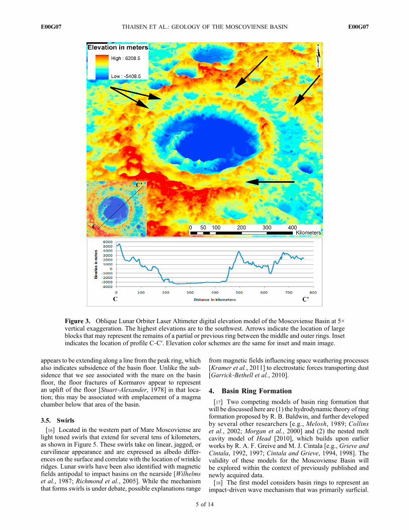
based on superposition relationships and crater‐countingtechniques. The features of the basin have experienced asignificant number of impacts since its initial formation andhave subsequently been degraded over time. Past studies havesuggested that the basin contains as many as five rings locatedat 140, 220, 300, 420, and 630 km [Pike and Spudis, 1987].Wood and Head [1976] identified three rings at 205, 410, and700 km; Wilhelms et al. [1987] identified only two rings at210 and 445 km and suggested the possibility of a third ring.We have identified three distinct rings using LOLA topo-graphic data; an inner peak ring, a middle ring, and an outerring that are 185, 430, and 650 km in diameter, respectively.The floor of the basin is about 7 km deep relative to the crestof the outer rim. Although the floor of the basin is elongated,the middle ring is nearly circular and has a length to widthratio of 1.06:1 (NE‐SW:NW‐SE).Most basins have generallyconcentric rings that are found at ∼20.5D spacings (whereD isthe diameter of the adjacent interior ring) [Chadderton et al.,1969; Pike and Spudis, 1987]. However, the geographiccenters of the peak ring and the main ring of the MoscovienseBasin are offset along a line to the southwest, ∼90 and ∼60 km,respectively, relative to the center of the outer ring, as illus-trated in Figure 2.[9] The inner peak ring is represented by a continuous half
ring of ∼185 km diameter that is open to the northeast. Asshown from the topographic profiles in Figure 2, the half ringis typically 20–25 km across and elevated ∼2–3.5 km abovethe present basin floor; at its ends, it grades into lower massifsthat become embayed by mare and are no longer exposed atthe surface or are absent. The inside scarps of the existingpeak ring typically slope toward the center of the basin atangles at 10°–25° and rarely exceed 35°. Surrounding theoutside of the exposed inner peak ring is a nearly continuousplatform that extends slightly beyond the peak ring to thenorth and east and is elevated nearly a kilometer above themare‐filled basin floor.[10] According to the identification of basin rings in the
Orientale Basin by Head [1974], the middle ring representsthe approximate location of the original crater rim. Themiddle ring of Moscoviense Basin is a nearly continuous ringof massifs with a diameter of approximately 430 km, whichagrees well with the diameter of the main ring as identified byWilhelms et al. [1987] andWood and Head [1976] and one ofthe rings identified by Pike and Spudis [1987]. The elevationof the middle ring crest is variable but is typically 6–7 kmabove the mare that covers the basin floor. Between themiddle ring and outer ring, several distinct terraces can befound that correlate well with the elevation of the middle ring(Figure 3). These terraces are not continuous, but ifconnected, they form an approximately elliptical outlinebetween the two rings.[11] The outer ring of the basin is a discontinuous ring that
is particularly disturbed to the east‐southeast. This scarp has adiameter of approximately 650 km, and when compared tothe rings of the Orientale Basin as described by Head [1974],this ring corresponds with the outer ring that formed in thelate stages of basin formation, as the crust collapsed into thenewly formed crater. The surrounding rim is generally higherto the west and south, with corresponding steeper slopes intothe basin than to the north and east, where there are lowerrims, typically gentler slopes, and distinct slump blocks thatare shown in Figure 3.
3.2. Mare
[12] Much of the floor of the Moscoviense Basin has beenfilled by mare basalts of varying compositions [e.g., Gillis,1998; Craddock et al., 1997; Kramer et al., 2008; Haruyamaet al., 2009; Morota et al., 2009]. They form an approxi-mately rectangular depression that trends southwest to north-east (Figure 2). The naming convention of these units followsthat used by Kramer et al. [2008]. The units have been iden-tified as an Imbrium age low‐Fe, low‐Ti mare (Im), which liesprimarily in the south; an Imbrium age low‐Ti mare (Iltm) thatlies in the northwest and overlies the Im; an Imbrium age high‐Ti mare (Ihtm) that is located to the east, and an Imbrium agemare associated with the Komarov crater (Ikm). The ages ofthese flows were recalculated using crater‐counting techniquesbyMorota et al. [2009]. Unit Imwas dated at 3.9 Ga, unit Iltmwas dated at 3.5 Ga, unit Ikm was dated as 3.3–3.5 Ga, andunit Ihtm was dated at 2.6 Ga, and thus placed within theEratosthenian system. Morota et al. [2009] appropriatelyrenamed the unit Ehtm to reflect the younger age. BothKramer et al. [2008] andMorota et al. [2009] suggested thatIkm is compositionally similar enough to Iltm that they couldbe a single contemporaneous unit. However, our analysis isprecluded because the unit Ikm was not mapped by M3. Twoother locations outside of the basin that contain mare havebeen identified in Figure 2; however, these maria do notappear to be related to any basin structures.[13] Since the location of the Moscoviense Basin is well
within the FHT [Jolliff et al., 2000], it is reasonable to assumethat this area would have some of the thickest crust on theMoon. However, a recent study by Ishihara et al. [2009],using data from the JapaneseMission, Kaguya, suggested thatthe crust immediately below the Moscoviense Basin is actu-ally the thinnest on the entire Moon. They suggested that thebasin most likely had a thick preimpact crust, but the impactresulted in an anomalously large mantle uplift [Namiki et al.,2008] for a basin of this size, indicating that this area mayhave already been atypical prior to the impact event.
3.3. Significant Craters
[14] There are two significant craters that are associatedwith the mare within the basin, the Titov andKomarov craters(Figure 4). Titov is a ∼30 km diameter crater in the northeastthat is surrounded by units Im and Ehtm, but lies outside ofM3 coverage. Surrounding the craters, unit Im appears to bemade up of ejecta that have been subsequently embayed byIltm and Ehtm flows. Komarov crater is a ∼80 km diametercrater that has partially obscured a smaller ∼50 km crater onthe eastern edge of the basin floor. The floor of Komarov ishighly fractured and was mapped as a separate mare unit(Ikm) by Gillis [1998] and Kramer et al. [2008]. However,Morota et al. [2009] considered Ikm and Iltm to be parts ofthe same unit based on their similar ages and Clementinespectral signatures. Unfortunately M3 has only limited cov-erage of the eastern edge of Kormarov crater that is outsideof the mare deposit.
3.4. Sinuous Rilles, Linear Rilles, and Wrinkle Ridges
[15] Gillis [1998] reported sinuous rilles and other volcanicedifices in and around the basin, using Clementine images.However, these features are not apparent in the M3 or Kaguyaimagery, and the observations using the higher‐resolution
THAISEN ET AL.: GEOLOGY OF THE MOSCOVIENSE BASIN E00G07E00G07
3 of 14
and optimally lit Kaguya terrain camera do not support allof the identifications made with lower‐resolution data. Asshown in Figure 4, wrinkle ridges have formed on the basinfloor parallel to the northeast scarp, perpendicular to the
length of the mare near its midpoint, as well as along an arc inthe west‐southwest area of the mare; these are all indicative ofsubsidence and contraction of the basin floor. In Figure 4, asingle linear rille can be seen along the eastern mare edge that
Figure 2. Mosaic of M3 imagery (band 84 at 2976.2 nm) referenced to a Lunar Orbiter Laser Altimetrydigital elevation model illustrating the location of the basin rings, the basin ring centers, mare/melt units,the location of mafic exposures (numbered for reference), and topographic profiles and their locations(dashed lines). White unit (Iltm), Imbrian low‐titanium mare basalt; green unit (Ehtm), Eratosthenianhigh‐titanium mare basalt; red unit (Im), Imbrian low‐titanium mare basalt (possible impact melt); blueindicates remote maria that do not appear to be associated with any Moscoviense Basin structure.
THAISEN ET AL.: GEOLOGY OF THE MOSCOVIENSE BASIN E00G07E00G07
4 of 14
appears to be extending along a line from the peak ring, whichalso indicates subsidence of the basin floor. Unlike the sub-sidence that we see associated with the mare on the basinfloor, the floor fractures of Kormarov appear to representan uplift of the floor [Stuart‐Alexander, 1978] in that loca-tion; this may be associated with emplacement of a magmachamber below that area of the basin.
3.5. Swirls
[16] Located in the western part of Mare Moscoviense arelight toned swirls that extend for several tens of kilometers,as shown in Figure 5. These swirls take on linear, jagged, orcurvilinear appearance and are expressed as albedo differ-ences on the surface and correlate with the location of wrinkleridges. Lunar swirls have been also identified with magneticfields antipodal to impact basins on the nearside [Wilhelmset al., 1987; Richmond et al., 2005]. While the mechanismthat forms swirls is under debate, possible explanations range
from magnetic fields influencing space weathering processes[Kramer et al., 2011] to electrostatic forces transporting dust[Garrick‐Bethell et al., 2010].
4. Basin Ring Formation
[17] Two competing models of basin ring formation thatwill be discussed here are (1) the hydrodynamic theory of ringformation proposed by R. B. Baldwin, and further developedby several other researchers [e.g., Melosh, 1989; Collinset al., 2002; Morgan et al., 2000] and (2) the nested meltcavity model of Head [2010], which builds upon earlierworks by R. A. F. Greive and M. J. Cintala [e.g., Grieve andCintala, 1992, 1997; Cintala and Grieve, 1994, 1998]. Thevalidity of these models for the Moscoviense Basin willbe explored within the context of previously published andnewly acquired data.[18] The first model considers basin rings to represent an
impact‐driven wave mechanism that was primarily surficial.
Figure 3. Oblique Lunar Orbiter Laser Altimeter digital elevation model of the Moscoviense Basin at 5×vertical exaggeration. The highest elevations are to the southwest. Arrows indicate the location of largeblocks that may represent the remains of a partial or previous ring between the middle and outer rings. Insetindicates the location of profile C‐C′. Elevation color schemes are the same for inset and main image.
THAISEN ET AL.: GEOLOGY OF THE MOSCOVIENSE BASIN E00G07E00G07
5 of 14
Coinciding with the excavation of the impact and immedi-ately following it, rebound and collapse of the floor beginsgenerating tsunami‐like waves that propagate outward andfreeze [Baldwin, 1972], preserving the ring structures asso-ciated with multiringed basins. The development of a peakring is proposed to result from the outer edges of the base ofa rebounding fluidized central peak solidifying, while therebounding interior portions remained in a fluid, or fluid‐like,state, and continued to collapse. Potential strengths of thismodel, noted by Spudis [1993], are the evidence for oscilla-tory uplift at terrestrial impact craters, and that this theorypossibly explains the (20.5D) ring spacing observed inmultiringed basins by Chadderton et al. [1969] and Pikeand Spudis [1987]. Potential weaknesses, also suggested bySpudis [1993], are that the physical plausibility of the sce-nario is uncertain, and there is evidence for deep structuresassociated with basin rings. Since the formation of the peakring is a direct consequence of the rebounding floor in thismodel; complete circular peak rings should be associatedwith all large basins. The partial peak ring in MoscovienseBasin would suggest that this model may not adequatelycharacterize peak ring development. The Moscoviense Basinalso does not possess concentric rings with 20.5D ring spacingthat would develop as a natural consequence of the surficialimpact‐driven wave mechanism. This model does not appearto explain the features seen within this basin.[19] The nested melt cavity model proposes that rings form
as a result of the interaction between the transient cavity, thedisplaced zone, and the melt cavity, all generated duringcomplex crater and basin formation. Cintala and Grieve[1998] suggested that as the transient crater size increases,the percentage of target rock being melted at the subimpactpoint will also increase. As it does, the nature of the transientcavity and its relationship to the displaced zone, and itssubsequent collapse, are fundamentally changed. Head
[2010] described that in the short term, modification isdominated by the strength differences that exist between thefluid melt of the inner cavity and the highly shocked, but solidrocks that exist within the displaced zone at the outer marginof the melt cavity, as described byCintala and Grieve [1998].Head [2010] proposed that the rocks that make up the tran-sitional zone between the melt cavity and the displaced zonerebound, moving up and laterally inward due to the crustalresponse to the transient cavity. This movement displacesthe fluid of the melt cavity and generates a peak ring. If thetransient melt cavity becomes large enough to penetrate thebase of the displaced zone, listric faulting into the basin willpropagate along the base of the displaced zone; this resultsin a slight movement inward of the transient cavity, whichslightly displaces the main ring and causes the developmentof an additional outer ring andmegaterrace at ∼1.5 crater radii[Head, 2010]. The formation of three concentric rings isnot inherently required by the Head [2010] model. This isbecause ring formation is a function of both the collapse of thetransient cavity and the size of the melt cavity, both of whichcould be influenced by the impact angle [Cintala and Grieve,1998]. This suggests that an elongated or elliptical‐shapedtransient cavity and/or melt cavity may result in offset andpartial rings, due to differences in the transient crater wallslopes and the subsequent faulting during the basin modifi-cation stage. In addition to being able to explain the offsetring configuration and the partial peak ring, this model alsoaddresses the crustal thinning that is recognized within theMoscoviense Basin.
Figure 5. Subimage fromM3 imageM3G20090528T130108highlighting swirls within western Mare Moscoviense.See Figure 4 for location of image. RGB image where R =700 nm, G = 500 nm, B = 460 nm with a 2% linear stretchand then converted to gray scale.
Figure 4. Kaguya image of Mare Moscoviense indicatingthe locations of wrinkle ridges, a rille, and the Titov andKormarov craters. White box outlines the location of Figure 5.Image Courtesy of JAXA.
THAISEN ET AL.: GEOLOGY OF THE MOSCOVIENSE BASIN E00G07E00G07
6 of 14
[20] The Moscoviense Basin has an unusual shape and ringdistribution. The variability among the size, shape, number ofrings, and ring spacing of basins on the Moon has been welldocumented [e.g., Chadderton et al., 1969; Hartmann andWood, 1971; Wood and Head, 1976; Wilhelms et al., 1987;Pike and Spudis, 1987; Melosh, 1989; Spudis et al., 1994;Wieczorek and Phillips, 1999]. However, these basins cangenerally be said to possess concentric rings with a ringspacing of 20.5D [Chadderton et al., 1969; Pike and Spudis,1987]. The rings of the Moscoviense Basin are significantlyoffset to the southwest, and there are two potential scenariosthat could account for this unusual configuration: (1) anoblique impact or (2) multiple impacts at this location.
4.1. Oblique Impact
[21] Experimental studies of oblique impacts by Gault andWedekind [1978] have demonstrated that they can result inelongate noncircular depressions with discontinuous ejectapatterns that become highly asymmetric. Schultz [1992] alsorecognized discontinuous ejecta patterns and partial peakrings that are offset up range and open in the downrangedirection of Venusian craters formed from oblique impacts.Cintala andGrieve [1998] suggested that impact angle wouldinfluence the downrange motion of the impact melt; thiswould produce an offset in the center of the rebound. Gaultand Wedekind [1978] observed that the cross‐sectional pro-files of experimental oblique impacts change with impactangle in the along‐trajectory direction. The geometry of theresulting craters generally tends to produce steeper slopes andlower rims in the up‐range direction, and more shallowextended slopes with higher rims in the downrange direction.TheMoscoviense Basin has just such a profile if viewed fromthe southwest to northeast, as shown in Figure 3. The basinpossesses a discontinuous ejecta blanket to the north and east,as mapped by Wilhelms and El‐Baz [1977] and Stuart‐Alexander [1978]. The primary differences between theexperimental work of Gault and Wedekind [1978] and thefeatures of the Moscoviense Basin (other than scale and
composition) are that the actual rim heights are higher to thesouthwest and lower to the northeast, the opposite of whatwould be predicted by their experiments. Also, their experi-mental work did not result in the formation of multiple rings.[22] The higher rim to the southwest may be due to the
addition of ejecta from the Mendeleev basin, which lies southof theMoscoviense Basin (Figure 1), and/or a combination ofsmall localized impacts on the outer rim that have raised thelocal topography in this area. Since the formation of multiplerings could not be addressed at the scales and with thematerials thatGault and Wedekind [1978] used in their study,it is unclear from their work whether the half ring, whichrepresents the peak ring, or the offset nature of the ring sys-tem, is a function of impact angle. However, the work bySchultz [1992] on oblique impacts did recognize partial peakrings that are offset up range and open in the downrangedirection, with discontinuous ejecta blankets surrounding thecrater. These features are all recognized in the MoscovienseBasin and suggest that Moscoviense may be the result ofan oblique impact.
4.2. Multiple Impacts
[23] Another possibility that was suggested by Wilhelmset al. [1987] is that the Moscoviense Basin and its unusualring configuration is the result of multiple impacts closelyconnected in time. This scenario could result from binaryasteroids impacting the surface nearly simultaneously or froma fragmented object; such an occurrence was dramaticallyobserved when comet Shoemaker‐Levy 9 broke up andimpacted Jupiter [Hammel et al., 1995]. The displacement ofthe ring centers along a linear trend to the southwest mayindicate preexisting structural constraints that developed dueto a prior impact event [Wilhelms et al., 1987] or possiblythrough the combination of two near‐simultaneous impacts.A difficultly in determining if multiple impacts were involvedin the formation of the Moscoviense Basin lies in that themore recent impact would tend to erase many of the surfacesignatures of previous impact events of equal or lesser mag-nitude. However, if the more recent impact was smaller andformedwithin a larger, older basin, features of each basinmaybe preserved, such as the outer ring of an older/larger basinand the inner rings of a smaller/younger basin. At least threedistinct and separate slump blocks exist between the main andouter rings of the northern half of Moscoviense Basin (seeFigure 3). These slump blocks may represent the remnants ofa preexisting ring within the current basin. In the event thatthe initial impact masses were comparable in size and struckthe Moon offset from one another, a figure 8 to ellipticalconfiguration of the middle ring may develop as two over-lapping craters are merged such as has been suggested forHumboldtianum basin [Lucchitta, 1978]. Although the shapeof the rings in Moscoviense appear to be circular, half of thepeak ring is either missing or has been embayed by mare andits shape cannot be confirmed. The roughly figure 8 shape ofthe basin floor may indicate the location where the floors oftwo basins overlap. However, this scenario would most likelyresult in an elliptical‐shaped basin rather than one with offsetcircular rings as is demonstrated in Figure 6.[24] Additional lines of evidence that may support the idea
of multiple impacts at Moscoviense are the thin crust that hasbeen suggested by Ishihara et al. [2009] and the increasedgravity anomaly reported by Namiki et al. [2008]. Basin‐
Figure 6. An idealized scenario where overlapping transientcavities of similar size generate a figure 8 ring configuration,similar to that suggested for the development of Humboldtia-num Basin by Lucchitta [1978]. Collapse of the adjacenttransient cavities develops generally elliptical rings.
THAISEN ET AL.: GEOLOGY OF THE MOSCOVIENSE BASIN E00G07E00G07
7 of 14
sized impacts result in the development of mass concentra-tions (mascons) due to mantle uplift [e.g., Wise and Yates,1970; Neumann et al., 1996; Wieczorek and Phillips, 1999]and the combination of mare emplacement [Solomon andHead, 1980]. If multiple separate basin‐forming sized im-pacts occurred at the same location, it is possible to envision ascenario where separate episodes of mantle uplift could resultin a stepwise raising of the crust‐mantle boundary. If, on theother hand, the response of the crust‐mantle boundary is adirect result of the size and depth of the transient cavity, then ascenario where two impacts occur nearly simultaneously mayresult in significantly more material being removed and froma greater depth. This scenario might proceed as follows and isillustrated in Figure 7: (1) The first bolide impacts into thesurface and excavates a transient cavity. (2) Before the tran-sient cavity begins to collapse, a second bolide impacts intothe floor of the existing transient cavity and generates a sec-ond transient cavity within the first that penetrates deeper into
the crust. (3) Since the second impact would define the finalshape and depth of the combined transient cavity, offset ringsor an elliptical ring configuration could result as the rimcollapses into the basin and the floor rebounds. The uplift ofthe crust‐mantle boundary may be significantly greater thanexpected for a basin of the size of Moscoviense due to itsgreater depth of excavation. A multiple‐impact scenarioseems plausible and can be used to explain the unusuallyhigh‐gravity anomaly and thin crust that has been reported atMoscoviense.
5. Moscoviense Formation Scenario
[25] It is impossible to say exactly what the surface of theMoonwas like prior to the creation of theMoscoviense Basin.The crust of theMoon had solidified and the impact flux in theearly solar system had waned considerably [Hartmann,1965]. However, the proposed late heavy bombardment[Tera et al., 1974] had recently begun (i.e., ∼4.0 Ga) andsignificant basin‐forming impacts were once again occurringon the Moon. The 2500 km wide South Pole‐Aitken basin[Spudis et al., 1994], also referred to as the big backside basinby Wilhelms et al. [1987], had already formed resulting ina redistribution of crustal material across much of the lunarsurface. That single event is modeled to have covered theMoscoviense Basin area with one to two kilometers of ejecta[Petro and Pieters, 2008], potentially filling in or obscuringpreexisting significant craters or small basins.
5.1. Impact
[26] The impact event(s) that formed the MoscovienseBasin, occurred during the Nectarian Period (3.85–3.92 Ga)[Wilhelms et al., 1987], resulting in an excavated basin withmultiple rings. The impact would have produced significantmelt within the displaced zone at the deepest part of thetransient cavity. As the walls of the transient cavity collapsedinward and the floor of the basin simultaneously reboundedupward, the edges of the melt cavity collapsed and formed thepeak ring. The melt that had been in the melt cavity wouldhave flowed and collected in low‐lying areas of the basin asthe basin stabilized.Wilhelms and El‐Baz [1977] and Stuart‐Alexander [1978] identified lineated material around thebasin to the north and east of the basin that appears to rep-resent discontinuous ejecta deposits from the impact event.
5.2. Mare Emplacement
[27] During large‐scale impact events, a considerableamount of crustal overburden is removed and redistributedaround the impact site. The removal of this material causesthe temperature and pressure gradients within the crust toreadjust and may instigate melting and magma productionbelow the basin [Elkins‐Tanton et al., 2004]. This redistri-bution of geothermal gradients can also result in convectivemotion of the crust below the basin; resulting in horizontaland vertical stresses that adjust to the new configuration of thesurface and crust‐mantle boundary, further instigating moremelting [Elkins‐Tanton et al., 2004]. The lower‐density meltbegins to form diapirs and ascend until it encounters a layerof crust less dense than itself, where it stalls in a density trap,or at a rheological boundary that prevents further ascension[Head and Wilson, 1992]. As more and more melt collects atthese locations, the pressure begins to build until dike prop-
Figure 7. Multiple‐impact scenario with two near‐simultaneous impacts. (top) Transient cavity, displaced zone,and melt cavity develop from first impact event as describedby Head [2010]. (middle) Second impact excavates deeperinto the crust before the first transient cavity collapses.(bottom) Collapse of the displaced zones from each ofthe impacts into the melt cavities and transient cavity of thesecond impact results in filling of the deepest part of thebasin, while oversteepened walls collapse and form terracesin part of the basin and shallower slopes develop in the rest ofthe basin. The deeper excavation and removal of overburdenof the multiple impacts result in a greater response from thecrust‐mantle boundary than would occur with an individualimpact.
THAISEN ET AL.: GEOLOGY OF THE MOSCOVIENSE BASIN E00G07E00G07
8 of 14
agation is initiated. If the dike propagates to the surface, someof the magma in the dike will extrude onto the surface;otherwise, the dikes will stall and solidify below the surface[Head and Wilson, 1992]. At this location, partial meltingmay have been instigated by the impact event and providedthe additional impetus required for the basaltic magmas,which resulted from the concentration of the radioactiveelements in the residual KREEP [Warren, 1985], to reach thesurface.[28] Mare volcanism commenced in Moscoviense during
the upper Imbrian epoch (3.2–3.8 Ga) [Wilhelms and El‐Baz,1977; Stuart‐Alexander, 1978; Haruyama et al., 2009;Morota et al., 2009], with the final basalt flows occurringpossibly as recent as ∼2.5–2.6 Ga [Haruyama et al., 2009;Morota et al., 2009]. There are no obvious fissures, vents, orsinuous rilles leading into the basin that indicate the locationof the volcanic activity that led to the filling of the basin floor,at the resolution of currently available imagery. Previousinterpretations of sinuous rilles within the basin by Gillis[1998] cannot be corroborated. There are also no recogniz-able distinct flow margins between the different mare units.Mare unit delineations are based on the mineralogical vari-ability seen in multispectral images, surface textures, andalbedo. The slope of the basin floor from northeast tosouthwest and the general elongate shape of the Iltm and
Ehtm units suggest that the source vents of the mare aresomewhere in the north or northeastern region of the basinfloor, as suggested by Gillis [1998]. The Im unit is topo-graphically higher than the Iltm and Ehtm units, especially inthe vicinity of the peak ring, and is exposed in crater rims andejecta on the basin floor. The unit is highly cratered anddegraded, more so than any of the other deposits on the basinfloor. It has been assigned an age of 3.9 Ga by Morota et al.[2009], which suggests that it is the oldest surface unit withinthe basin floor and corresponds with the age of the basin itself.The unit extends from the southern edge of the Iltm and Ehtmunits down toward the lowest portion of the basin floor andthen uphill toward the base of the peak ring. It is exposedin the north end of the basin as uplifted crater rims and ejectaand at the edges of the basin floor to the northeast. Theserelationships suggest that the Im unit may be impact melt thatfilled the floor of the basin and not a mare basalt deposit thathas subsequently covered it. The reclassification of the Imunit as an impact melt more closely resembles the classifi-cation of the unit by Craddock et al. [1997] as a question-able pyroclastic deposit or possible melt sheet based onClementine data. Other mare units have been identified out-side of the basin to the north and south by Stuart‐Alexander[1978] and Gillis [1998]. These deposits occur within cra-ters at 13°54′47 N, 153°58′48E and at 45°26′1N, 150°48′27E
Figure 8. Mean apparent reflectance spectra collected from the basin floor units in imageM3G20081229T022350. (top) SCREP selected spectra of primary units and (bottom) surface spectra.The color of each spectral profile corresponds to the unit color in Figure 2. Note that spectra are not ther-mally or photometrically corrected, and this may influence the shape of the 2 mm band.
THAISEN ET AL.: GEOLOGY OF THE MOSCOVIENSE BASIN E00G07E00G07
9 of 14
(Figure 2). However, there is no evidence that these basaltsare necessarily associated with Moscoviense Basin, basedon features exposed at the lunar surface.
6. Characterization of the Mineralogical Unitsin and Around Moscoviense
[29] With M3 data, we have identified the different mareunits utilizing three separate band ratios that highlight dif-ferences in mineralogical composition: band ratio 1618 nm/730 nm examines the continuum slope; band ratio 1209 nm/1618 nm accentuates differences within the slope ratio; andband ratio 580 nm/730 nm compares the band strengths atultraviolet versus visible wavelengths. We used the SmallCrater Rim and Ejecta Probing (SCREP) procedure [Kramer,2010] to extract spectral information from pixels on the rimsand proximal ejecta of small, immature craters (0.5–5 kmin diameter). These small craters act as windows throughthe ubiquitous, obscuring regolith, exposing the underlyinglithology [McCord and Adams, 1973; Staid and Pieters,2000; Kramer et al., 2007, 2008; Kramer, 2010]. Analysisis focused on the rims and proximal ejecta of the cratersbecause these are the locations that best expose the pristinebedrock composition, while simultaneously avoiding photo-metric effects due to steep slopes. Impact‐cratering studiesand analysis of impact ejecta mechanics demonstrate that nearthe crater rim, the original stratigraphy of the impact target isinverted [Melosh, 1989]. This area represents the thickest partof the crater ejecta and thus consists of the most concentratedor highest proportion of native material compared to foreignmaterials that collectively make up the regolith. Furthermore,
the rim and proximal ejecta suffer the least amount of post-impact regolith buildup [Kramer, 2010]. Impact gardeningand other soil maturation processes are continuous phenom-ena. Regolith production is progressively obscuring thefreshly exposed bedrock. Thus, despite information fromthe least mature impacts, the craters from which we derivecompositional values are still contaminated by lateral mix-ing from foreign terrains. The crater floor, which representsthe greatest depth of penetration, has been used for extractingcompositional information. However, it would be coveredwith regolith produced since excavation, as would any flatregion of the lunar surface, and would also contain addi-tional material slumped off the crater wall. Kramer [2010]gives a thorough discussion of the SCREP procedure andrationale.[30] The mean spectra of the basin floor surface units
and their SCREP‐selected spectra shown in Figure 8. Thesespectral analyses are a significant improvement over previousstudies, by virtue of the improved spectral capabilities ofM3 instrument. The Im unit is characterized by a very weakfeature at 1 mm, but due to the strong thermal componentbeyond 2 mm, there is no clear 2 mm band. This, along withthe high albedo of the unit, suggests that Im is highly feld-spathic with little or nomafic minerals present. These spectralcharacteristics are consistent with impact melt [Tompkins andPieters, 2010]; thus, unit Im may be the battered remains ofthe basin floor impact melt sheet. Units Iltm and Ehtm, havestrong ferrous bands indicating that they are basaltic units.The absorption features of the surface units (soils) are sig-nificantly subdued due to space weathering, and stand incontrast to the fresh basalt spectra for each unit as shown in
Figure 9. (a) M3 image M320081229T022350 750 nm albedo and (b) corresponding units of two‐dimensional scatterplot. (c) M3 color composite where R is the integrated band depth at 1000 nm, Gis the integrated band depth at 2000 nm, and B is albedo at 1489 nm (band 46). (d) Two‐dimensionalscatterplot and pixel density slice indicating transition of mafic to feldspathic units; x axis is albedo at1489 nm (band 46), and y axis is the integrated band depth at 1000 nm. Colors in Figures 9b and 9d corre-spond with units of green, Ehtm (i.e., remove E‐) unit; red, Im (i.e., remove S‐) unit; and blue, peak ring.
THAISEN ET AL.: GEOLOGY OF THE MOSCOVIENSE BASIN E00G07E00G07
10 of 14
Figure 8. A two‐dimensional scatterplot showing the inte-grated band depth at 1000 nm versus the albedo at 1489 nm isshown in Figure 9. Pixels with a strong absorption around1000 nm (mafic minerals) plot higher in the y axis direction,and pixels that have a stronger albedo at 1489 nm (attributedto a higher FAN abundance) will plot at higher values alongthe x axis. The plot (Figure 9) clearly delineates between unitsIm, Ehtm, and the peak ring. We interpret this to indicate thatunit Im is compositionally intermediate between the basalticunit Ehtm and the peak ring material, which would beexpected of an impact melt derived from melted and mixedupper (feldspathic) and lower (mafic) crustal material.[31] The FHT surrounding the Moscoviense Basin is gen-
erally spectrally bland across the spectral range of M3, asis expected for fractured and shocked anorthositic material.However, Yamamoto et al. [2010] identified several locationswithin the peak ring and the main ring that exhibit significantolivine signatures. One of the locations having an olivine‐dominated lithology was also identified by Isaacson andPieters [2010] at 32.568°N, 143.760°E, which is northwest
of the mare in the middle ring (Figure 2, mafic exposure 1).There are several craters around the basin, identified inFigure 2, that have excavated materials from below thesurface that display strong mafic absorption features.Figure 10 represents spectra from two craters that exposedmafic material within or adjacent to the main ring. Thesespectra were obtained from a ∼10 km crater located at24.169°N, 155.128°E (Figure 2, mafic exposure 2) and a∼15 km crater at 25.395°N, 154.054°E (Figure 2, maficexposure 3). Both these craters exhibit a weak but broadferrous band near 1 mm that could be due to pyroxene and/orolivine. Additional spectra of mafic exposures (Figure 11)can be found north of the basin, within the exposed centralpeak of a ∼30 km crater at 44.150°N, 141.833°E (Figure 2,mafic exposure 4), and in a ∼7.5 km crater at 28.020°N,161.877°E in the outer ring (Figure 2, mafic exposure 5).These have distinct features that occur at shorter wavelengths,indicative of small amounts of low‐Ca pyroxene. There areseveral other small exposures of mafic material around thebasin, but it is difficult to determine definitively from this
Figure 10. Average apparent reflectance of 3 × 3 window from two craters along the eastern middle ring(see mafic exposures in Figure 2 for locations) from M3 image M3G20090624T071103. Absorptions at1 and 2 mm indicate that mafic compositions have been exposed within the FAN crust adjacent to the middlering by impacts. Note that spectra are not thermally or photometrically corrected, and this may influence theshape of the 2 mm band.
Figure 11. Average apparent reflectance of 3 × 3 window from two craters outside of the outer ring (seemafic exposures in Figure 2 for locations) from M3 images M3G20090528T213152 (crater 4 north) andM3G20090720T214000 (crater 5 east). Absorptions at 1 and 2 mm indicate that mafic compositions havebeen exposed within the FAN crust adjacent to the outer ring by impacts. Note that spectra are not thermallyor photometrically corrected, and this may influence the shape of the 2 mm band.
THAISEN ET AL.: GEOLOGY OF THE MOSCOVIENSE BASIN E00G07E00G07
11 of 14
initial analysis whether the origin of this material is crypto-mare, pyroclastic deposits, or mafic intrusions.[32] The peak ring is the most diverse lithologic unit
within the basin, with several areas where unexpectedmineralogies have been exposed and discovered.Pieters et al.[2011] have identified several areas within the peak ringwhere olivine, orthopyroxene, and magnesium‐rich spinel(MgAl2O4) spectra appear as isolated diffuse units. Theseexposures do not appear to be associated with any impactcraters, significant albedo changes, or geomorphologicalfeatures, suggesting that they are integral components of thepeak ring that were exposed when the basin formed. Pieterset al. [2011] did not detect any other mafic minerals (i.e.,<5%) associated with the magnesium‐rich spinel but did findthat some of the olivine and orthopyroxene exposures aregeographically near one another.
7. Interpretation and Summary
7.1. Basin Formation
[33] There are several observations that make the Mos-coviense Basin unusual. The centers of the rings that make upthe Moscoviense Basin are offset along a line, the elongatenature of the basin floor, the significant positive gravityanomaly within the basin, the diverse basalt compositions, thepresence of sparse farside mare deposits, and the revelationthat the thinnest crust on the entire Moon is found under abasin that is surrounded by what is otherwise very thick crust(∼60–75 km). All of these things together suggest that thetypical scenarios related to basin formation may not entirelyapply to the Moscoviense Basin.[34] We have explored the possibility that the basin is the
consequence of a single oblique impact. This scenario isconsistent with the offset configuration of the rings, the par-tial peak ring, the elongated nature of the basin floor, steepuprange slopes and gentler downrange slopes, and the dis-continuous ejecta. However, since a single oblique impactwould distribute the kinetic energy of the bolide horizontallyas well as vertically, it is not clear why it would induce sucha significant response directly below the basin at the crust‐mantle boundary. So while an oblique impact does explainthe surface features that exist at Moscoviense, it doesnot satisfactorily explain the thin crust, significant gravityanomaly present, or the abundant mare that are recognizedthere.[35] Another possibility to explain the features of Mos-
coviense is that multiple impacts were involved in the for-mation of the basin. The scenario of a smaller basin formingwithin the confines of an older and larger preexisting basinmay account for the offset ring configuration as well as thepotential partial remnants of a ring between the main andouter rings and the elongated basin floor. In such a scenario,uplift of the crust‐mantle boundary in response to the twobasin forming events may be sufficient to explain the thincrust and associated significant positive gravity anomaly,which would represent a mantle plug intruding into the FHTcrust. Since the uplift of the crust‐mantle boundary is sosignificant, dike propagation from the uplifted crust‐mantleboundary to the surface can explain the presence of the maredeposits at this location.[36] We have also explored the slight modification of the
previous scenario, in which a nearly simultaneous double
impact occurs. The combined excavation by two bolides, oneimmediately following the other, would excavate a very deeptransient cavity without significantly increasing the diameterof the crater at the surface. The collapse of the transient cratercould result in an elongated crater floor, if the second bolideimpacted off center from the first. This could account for theoffset rings; since the main ring would form as a result ofthe final transient cavity and the peak ring would form fromthe collapse of the displaced zone into the skewed, expandingmelt cavity. The asymmetric collapse could suggest why halfof the peak ring extends above the basin floor and the rest iseither nonexistent or buried under mare. Since the expandedmelt cavity became elliptical instead of hemispherical and thetransient cavity had become deeper, the displaced zone wouldcollapse into the melt cavity instead of becoming part ofthe peak ring. Then the outer ring would form as a responseto the entire excavated cavity. This scenario has the potentialto explain the gravity anomaly, thin crust, farside mare, andpotentially the offset ring structure of the basin, and should beconsidered despite the complicated formational mechanisminvolving dual impacting bolides.[37] It is possible that the gravity anomaly and thin crust
are not directly related to the formation of the MoscovienseBasin, as viewed today. It could be, that prior to the impact(i.e., ≥4.0 Ga), significant secondary plutonic activity hadalready propagated dikes throughout the region, and theMoscoviense impact event, and isolated craters across thesurface, have subsequently excavated some of the dikes andplutons that resulted from this activity. If this is the case, asingle oblique impact scenario may be the most probable forthe Moscoviense Basin.
7.2. Basin Rings
[38] Moscoviense Basin is within the FHT [Jolliff et al.,2000], and the excavation of the rings has resulted in theexposure of several mafic signatures within this highly feld-spathic region. Each of the rings has at least two localitieswhere subsequent impacts have exposed mafic material, andthe peak ring has turned out to be the most mineralogicallydiverse area of the basin [Pieters et al., 2011]. According tothe Head [2010] basin ring formation model that we areusing, the material that makes up the peak ring corresponds tothe deepest part of the crust exposed by the basin‐formingevent. The shallow slopes where the unusual peak ringmineralogies have been found lack signs of recent impact,suggesting that they represent integral parts of the crust thathave been moved from depth and exposed at the surface. Theother areas within the middle ring and the outer ring that havemafic signaturesmay represent plutonicmaterial that reached,or nearly reached, the surface prior to basin formation.
7.3. Impact Melt
[39] The 3.9 Ga Im unit is the oldest unit and coincides withthe formation of the basin. The age and topographic rela-tionship of this unit with respect to the other mare depositsand the peak ring, as well as its spectral nature suggest thatthis unit is transitional between the mafic mineralogy of themare and the feldspathic mineralogy of the surrounding peakring material. Our interpretation of this transitional unit is thatit represents impact melt from the formation of the basin anddoes not represent a mare deposit. The composition of theIm unit likely reflects the melting and mixing of mafic and
THAISEN ET AL.: GEOLOGY OF THE MOSCOVIENSE BASIN E00G07E00G07
12 of 14
feldspathic lithologies during the basin impact event; whichincorporated mafic igneous intrusions, possibly lower crust,part of the bolide, and large amounts of FAN.
7.4. Mare Volcanism
[40] Mare deposits within the basin range in age from 3.5 to2.6 Ga [Morota et al., 2009]. The Iltm unit has an inter-mediate albedo relative to the Im and Ehtm units at 1489 nm.It has been assigned an age of 3.5 Ga and has spectra con-sistent with a basaltic mare. The Ehtm unit has a low albedo,has been assigned an age of 2.6 Ga, and is the youngestunit within the basin. The strong ferrous bands, as seen inFigure 8, are consistent with basaltic mare. The mare unitsthat have been identified to the north and south of the basin donot appear to be directly related to the maria within the basin.[41] TheMoscoviense Basin is an interesting feature on the
Moon that is providing us with the opportunity to explore theearly differentiation of the crust and the subsequent periodof later magmatic activity that intruded into the FHT. Theunusual mineralogies that have been exposed suggest thepresence of igneous intrusions within the FHT that werenot seen at the surface during the brief Apollo or Luna mis-sions. Further study of this part of the Moon may lead toa more thorough understanding of the magmatic history ofthe Moon and other terrestrial planets that have undergonedifferentiation.
[42] Acknowledgments. M3 is supported as a NASA Discovery Pro-gram mission of opportunity. The science results and science validation issupported through NASA contract NNM05AB26C. The M3 team is honoredto have had the opportunity to fly as a guest instrument on Chandrayaan‐1and is grateful to all the ISRO team that enabled M3 data to be returned.We gratefully acknowledge the valuable input to this project by the publicrelease of SELENE Terrain Camera data and LRO Laser Altimeter data.
ReferencesBaldwin, R. B. (1972), The tsunami model of the origin of ring structuresconcentric with large lunar craters,Phys. Earth Planet. Inter., 6(5), 327–339,doi:10.1016/0031-9201(72)90056-8.
Boardman, J. W., C. M. Pieters, R. O. Green, S. Lundeen, P. Varansi,J. Nettles, N. E. Petro, P. J. Isaacson, S. Besse, and L. A. Taylor(2011), Measuring moonlight: An overview of the spatial properties,lunar coverage, selenolocation and related level 1B products of the MoonMineralogy Mapper, J. Geophys. Res., doi:10.1029/2010JE003730,in press.
Chadderton, L. T., F. G. Krajenbrink, R. Katz, and A. Poveda (1969),Standing waves on the Moon, Nature , 223(5203), 259–263,doi:10.1038/223259a0.
Cintala, M. J., and R. A. Grieve (1994), The effects of differential scalingof impact melt and crater dimensions on lunar and terrestrial craters:Some brief examples, Spec. Pap. Geol. Soc. Am., 293, 51–59.
Cintala, M. J., and R. A. F. Grieve (1998), Scaling impact melting and cra-ter dimensions: Implications for the lunar cratering record, Meteorit.Planet. Sci., 33(6), 1343, doi:10.1111/j.1945-5100.1998.tb01320.x.
Clark, R. N., C. M. Pieters, R. O. Green, J. W. Boardman, and N. E. Petro(2011), Thermal removal from near‐infrared imaging spectroscopy dataof the Moon, J. Geophys. Res., doi:10.1029/2010JE003751, in press.
Collins, G. S., H. J. Melosh, J. V. Morgan, and M. R. Warner (2002),Hydrocode simulations of Chicxulub Crater collapse and peak‐ring for-mation, Icarus, 157(1), 24–33, doi:10.1006/icar.2002.6822.
Craddock, R. A. R., S. Mark, B. R. Hawke, and A. S. McEwen (1997),Clementine‐based geology of the Moscoviense Basin, lunar farside,Lunar Planet. Sci., XXVIII, 1499.
Elkins‐Tanton, L. T., B. H. Hager, and T. L. Grove (2004), Magmaticeffects of the lunar late heavy bombardment, Earth Planet. Sci. Lett.,222(1), 17–27, doi:10.1016/j.epsl.2004.02.017.
Garrick‐Bethell, I., J. W. Head III, and C. M. Pieters (2010), Spectral prop-erties of lunar swirls and their formation and dust transport, Proc. LunarPlanet. Sci. Conf., 41st, 2675.
Gault, D. E., and J. A. Wedekind (1978), Experimental impact “craters”formed in water: Gravity scaling realized, Eos Trans. AGU, 59(12), 1121.
Gillis, J. J. (1998), The composition and geologic setting of mare deposits onthe far side of the Moon, Ph.D. thesis, 248 pp., Rice Univ., Houston, Tex.
Goswami, J. N., and M. Annadurai (2008), Chandrayaan‐1 mission to theMoon, Acta Astronaut., 63(11–12), 1215–1220, doi:10.1016/j.actaastro.2008.05.013.
Grieve, R. A. F., and M. J. Cintala (1992), An analysis of differentialimpact‐melt crater‐scaling and implications for the terrestrial impactrecord, Meteoritics, 27(5), 526–538.
Grieve, R. A. F., and M. J. Cintala (1997), Planetary differences in impactmelting, Adv. Space Res., 20(8), 1551–1560, doi:10.1016/S0273-1177(97)00877-6.
Hammel, H., et al. (1995), HST imaging of atmospheric phenomena createdby the impact of comet Shoemaker‐Levy 9, Science, 267(5202), 1288–1296,doi:10.1126/science.7871425.
Hartmann, W. K. (1965), Secular changes in meteoritic flux through thehistory of the solar system, Icarus, 4(2), 207–213, doi:10.1016/0019-1035(65)90062-X.
Hartmann, W. K., and C. A. Wood (1971), Moon: Origin and evolution ofmulti‐ring basins, Earth Moon Planets, 3(1), 3–78.
Haruyama, J., et al. (2009), Long‐lived volcanism on the lunar farsiderevealed by SELENE terrain camera, Science, 323(5916), 905–908,doi:10.1126/science.1163382.
Head, J. W. (1974), Orientale multi‐ringed basin interior and implicationsfor the petrogenesis of lunar highland samples, Earth Moon Planets,11(3), 327–356.
Head, J. W., III (1976), Lunar volcanism in space and time, Rev. Geophys.,14(2), 265–300, doi:10.1029/RG014i002p00265.
Head, J. W. (2010), Transition from complex craters to multi‐ringed basinson terrestrial planetary bodies: Scale‐dependent role of the expandingmelt cavity and progressive interaction with the displaced zone, Geophys.Res. Lett., 37, L02203, doi:10.1029/2009GL041790.
Head, J. W., and L. Wilson (1992), Lunar mare volcanism—Stratigraphy,eruption conditions, and the evolution of secondary crusts, Geochim.Cosmochim. Acta, 56(6), 2155–2175, doi:10.1016/0016-7037(92)90183-J.
Hiesinger, H., and J. W. Head (2006), New views of lunar geoscience:An introduction and overview, Rev. Mineral. Geochem., 60, 1–81,doi:10.2138/rmg.2006.60.1.
Isaacson, P. J., and C. M. Pieters (2010), Deconvolution of lunar olivinereflectance spectra: Implications for remote compositional assessment,Icarus, 210, 8–13, doi:10.1016/j.icarus.2010.06.004.
Ishihara, Y., S. Goossens, K. Matsumoto, H. Noda, H. Araki, N. Namiki,H. Hanada, T. Iwata, S. Tazawa, and S. Sasaki (2009), Crustal thicknessof the Moon: Implications for farside basin structures, Geophys. Res.Lett., 36, L19202, doi:10.1029/2009GL039708.
Jolliff, B. L. (2006), New Views of the Moon, 721 pp., Mineral. Soc. ofAm., Chantilly, Va.
Jolliff, B. L., J. J. Gillis, L. A. Haskin, R. L. Korotev, and M. A. Wieczorek(2000), Major lunar crustal terranes: Surface expressions and crust‐mantle origins, J. Geophys. Res., 105(E2), 4197–4216, doi:10.1029/1999JE001103.
Kramer, G. Y. (2010), Characterizing bedrock lithologies using SmallCrater Rims and Ejecta Probing (SCREP), Adv. Space Res., 45(10),1257–1267, doi:10.1016/j.asr.2009.12.006.
Kramer, G. Y., J. P. Combe, and T. B. McCord (2007), Characterizinglunar crustal geology, Eos Trans. AGU, 88(52), Fall Meet. Suppl.,Abstract P41A‐0201.
Kramer, G. Y., B. L. Jolliff, and C. R. Neal (2008), Distinguishing high‐alumina mare basalts using Clementine UVVIS and Lunar ProspectorGRS data: Mare Moscoviense and Mare Nectaris, J. Geophys. Res.,113, E01002, doi:10.1029/2006JE002860.
Kramer, G. Y., et al. (2011), Newer views of the Moon: Comparing spectrafrom Clementine and the Moon Mineralogy Mapper, J. Geophys. Res.,doi:10.1029/2010JE003728, in press.
Lucchitta, B. K. (1978), Geologic map of the north side of the Moon,1 map, U.S. Geol. Surv., Reston, Va.
McCord, T. B., and J. B. Adams (1973), Progress in remote optical analysisof lunar surface composition, Earth Moon Planets, 7(3–4), 453–474.
Melosh, H. J. (1989), Impact Cratering: A Geologic Process, 245 pp.,Oxford Univ. Press, New York.
Morgan, J. V., M. R. Warner, G. S. Collins, H. J. Melosh, and G. L.Christeson (2000), Peak‐ring formation in large impact craters: Geo-physical constraints from Chicxulub, Earth Planet. Sci. Lett., 183(3–4),347–354, doi:10.1016/S0012-821X(00)00307-1.
THAISEN ET AL.: GEOLOGY OF THE MOSCOVIENSE BASIN E00G07E00G07
13 of 14
Morota, T., et al. (2009), Mare volcanism in the lunar farside Moscovienseregion: Implication for lateral variation in magma production of the Moon,Geophys. Res. Lett., 36(21), L21202, doi:10.1029/2009GL040472.
Namiki, N., H. Hanada, T. Iwata, and R. V. Teams (2008), Lunar far sidegravity from the Kaguya (SELENE) mission and dichotomy of the Moon,Meteorit. Planet. Sci., 43(7), suppl., A114.
Neumann, G. A., M. T. Zuber, D. E. Smith, and F. G. Lemoine (1996), Thelunar crust: Global structure and signature of major basins, J. Geophys.Res., 101(E7), 16,841–16,843, doi:10.1029/96JE01246.
Petro, N. E., and C. M. Pieters (2008), The lunar‐wide effects of basinejecta distribution on the early megaregolith, Meteorit. Planet. Sci.,43(9), 1517–1529, doi:10.1111/j.1945-5100.2008.tb01025.x.
Pieters, C. M., et al. (2011), Mg‐spinel lithology: A new rock‐type on thelunar farside, J. Geophys. Res., doi:10.1029/2010JE003727, in press.
Pike, R. J., and P. D. Spudis (1987), Basin‐ring spacing on the Moon,Mercury, and Mars, Earth Moon Planets, 39(2), 129–194, doi:10.1007/BF00054060.
Richmond, N. C., L. L. Hood, D. L. Mitchell, R. P. Lin, M. H. Acuña, andA. B. Binder (2005), Correlations between magnetic anomalies and sur-face geology antipodal to lunar impact basins, J. Geophys. Res., 110,E05011, doi:10.1029/2005JE002405.
Schultz, P. H. (1992), Atmospheric effects on ejecta emplacement andcrater formation on Venus from Magellan, J. Geophys. Res., 97(E10),16,183–16,248, doi:10.1029/92JE01508.
Shearer, C. K., and H. E. Newsom (2000), W‐Hf isotope abundances and theearly origin and evolution of the Earth‐Moon system, Geochim. Cosmo-chim. Acta, 64(20), 3599–3613, doi:10.1016/S0016-7037(00)00442-7.
Shearer, C. K., et al. (2006), Thermal and magmatic evolution of the Moon,Rev. Mineral. Geochem., 60(1), 365–518, doi:10.2138/rmg.2006.60.4.
Smith, J. V., A. T. Anderson, R. C. Newton, E. J. Olsen, P. J. Wyllie, A. V.Crewe, M. S. Isaacson, and D. Johnson (1970), Petrologic history of theMoon inferred from petrography, mineralogy and petrogenesis of Apollo11 rocks, Proc. Apollo 11 Lunar Sci. Conf., 1, 897–925.
Smith, D. E., et al. (2010), The Lunar orbiter laser altimeter investigationon the lunar Reconnaissance orbiter mission, Space Sci. Rev., 150(1–4),209–241, doi:10.1007/s11214-009-9512-y.
Snyder, G. A., L. A. Taylor, and C. R. Neal (1992), A chemical‐model forgenerating the sources of mare basalts: Combined equilibrium and frac-tional crystallization of the lunar magmasphere, Geochim. Cosmochim.Acta, 56(10), 3809–3823, doi:10.1016/0016-7037(92)90172-F.
Solomon, S. C., and J. W. Head (1980), Lunar mascon basins: Lava filling,tectonics, and evolution of the lithosphere, Rev. Geophys., 18(1), 107–141,doi:10.1029/RG018i001p00107.
Solomon, S. C., and J. Longhi (1977), Magma oceanography I: Thermalevolution, Proc. Lunar Sci. Conf., 8th, 583–599.
Spudis, P. D. (1993), The Geology of Multi‐Ring Impact Basins: The Moonand Other Planets, Cambridge Univ. Press, Cambridge, U. K.
Spudis, P. D., R. A. Reisse, and J. J. Gillis (1994), Ancient multiring basinson the Moon revealed by Clementine laser altimetry, Science, 266(5192),1848–1851, doi:10.1126/science.266.5192.1848.
Staid, M. I., and C. M. Pieters (2000), Integrated spectral analysis of maresoils and craters: Applications to eastern nearside basalts, Icarus, 145,122–139, doi:10.1006/icar.1999.6319.
Stuart‐Alexander, D. E. (1978), Geologic map of the central far side of theMoon, 1 map, U.S. Geol. Surv., Reston, Va.
Taylor, S. R., and S. M. McLennan (2009), Planetary Crusts: TheirComposition, Origin and Evolution, 378 pp., Cambridge Univ. Press,Cambridge, U. K.
Tera, F., D. A. Papanastassiou, and G. J. Wasserburg (1974), Isotopicevidence for a terminal lunar cataclysm, Earth Planet. Sci. Lett., 22(1),1–21, doi:10.1016/0012-821X(74)90059-4.
Tompkins, S., and C. M. Pieters (2010), Spectral characteristics of lunarimpact melts and inferred mineralogy, Meteorit. Planet. Sci., 45(7),1152–1169, doi:10.1111/j.1945-5100.2010.01074.x.
Warren, P. H. (1985), The magma ocean concept and lunar evolution,Annu. Rev. Earth Planet. Sci., 13(1), 201–240, doi:10.1146/annurev.ea.13.050185.001221.
Wieczorek, M. A., and R. J. Phillips (1999), Lunar multiring basins and thecratering process, Icarus, 139(2), 246–259, doi:10.1006/icar.1999.6102.
Wilhelms, D. E., and F. El‐Baz (1977), Geologic map of the east side of theMoon, U.S. Geol. Surv., Reston, Va.
Wilhelms, D. E., J. F. McCauley, and N. J. Trask (1987), The GeologicHistory of the Moon, 302 pp., U.S. Geol. Surv., Washington, D. C.
Wise, D. U., and M. T. Yates (1970), Mascons as structural relief on a lunarMoho, J. Geophys. Res., 75(2), 261–268, doi:10.1029/JB075i002p00261.
Wood, C. A., and J. W. Head III (1976), Comparison of impact basins onMercury, Mars and the Moon, Proc. Lunar Sci. Conf., 7th, 3629–3651.
Wood, J. A., J. S. Dickey, U. B. Marvin, and B. N. Powell (1970), Lunaranorthosites and a geophysical model of the Moon, Proc. Apollo 11Lunar Sci. Conf., 1, 965.
Yamamoto, S., et al. (2010), Possible mantle origin of olivine aroundlunar impact basins detected by SELENE, Nat. Geosci., 3, 533–536,doi:10.1038/ngeo897.
J. W. Head, P. Isaacson, J. Nettles, and C. M. Pieters, Departmentof Geological Sciences, Brown University, Box 1846, Providence,RI 02912, USA.G. Y. Kramer, Bear Fight Institute, 22 Fiddler’s Rd., Box 667, Winthrop,
WA 98862, USA.N. Petro, NASA Goddard Space Flight Center, Code 698, Greenbelt,
MD 20771, USA.L. A. Taylor and K. G. Thaisen, Planetary Geosciences Institute,
Department of Earth and Planetary Sciences, University of Tennessee,1412 Circle Dr., Knoxville, TN 37996‐1410, USA. ([email protected])
THAISEN ET AL.: GEOLOGY OF THE MOSCOVIENSE BASIN E00G07E00G07