Geomembrane as an Upstream Impermeable Blanket of Embankment Dams - Laboratory and Numerical Study R.C. Pierozan, S.H.C. Teixeira, G.L.S. Araújo, C.A. Teixeira Abstract. The use of geosynthetics has been a common practice in geotechnical engineering when the improvement of local soil characteristics is necessary. This paper presents an experimental and numerical study of the performance of HDPE geomembrane as impermeable blanket installed upstream of embankment dams, a treatment technique for very permeable foundation. Data based on project, field and laboratory tests of the Brazilian Salto Hydroelectric Power Plant were presented to gather information about the constructive method and to support further studies. A small-scale seepage model was constructed to represent the transverse section geometry of a hypothetical embankment dam, whose geometry was adopted based on Salto Hydroelectric Power Plant. Likewise, a numerical model was elaborated referring to the small-scale seepage model to perform several parametric analyses. The obtained results indicated that the geomembrane sealing system acts increasing the flow path through the dam foundation, resulting in lower pore-pressures into the dam. Additionally, the hydraulic parameters in the soil mass may vary considerably in case of damage to the geomembrane. In general, the study has shown that the use of synthetic membranes can be a good solution for treatment of pervious foundations and possible defects can lead to the reduction of their performance. Keywords: earth dam, geomembrane, impermeable blanket, numerical model, scaled model. 1. Introduction Embankment dams are normally large, complex, and costly works. Studies of alternatives to improve technical characteristics and to reduce construction cost of dams are important. One current alternative for improving soils, which has been common in geotechnical engineering works, is the use of geosynthetics. These materials have ad- ditional advantages compared to traditional materials as, for example, lower costs, shorter execution time and better ease of installation (Shukla, 2002; Koerner, 2012; Nichol- son, 2015). The increasing use of geosynthetics in recent years has attracted the attention of engineers and research- ers around the world, since those materials have peculiar characteristics when compared to traditional geotechnical materials. For this reason, new researches and design mod- els became necessary, especially when geosynthetics are applied in embankment dams. Geomembranes are among the most common types of geosynthetics. They are defined as a very low permeability synthetic membrane used with any geotechnical engineer- ing related material, with the purpose of controlling liquid or gas migration in a human-made work, structure or sys- tem (ASTM, 2015). High density polyethylene (HDPE) geomembranes are commonly used for the construction of reservoirs as liners for water, chemical products, mining tailings, among others (Giroud & Bonaparte, 1989; Tao et al., 1996; FHWA, 1998; Whitfield, 1996; Poulain et al., 2011, for instance). However, the efficiency of these barri- ers depends on the integrity of the synthetic membrane (Giroud & Touze-Foltz, 2003), in addition to other aspects, like the service life (Needham et al., 2006). Some researchers have studied aspects related to dam failure (e.g. Mahinroosta et al., 2015; Petaccia et al., 2016). Failures in dams and reservoirs protected by geomembra- nes have also been reported in the literature (e.g. Wu et al., 2008; Messerklinger, 2014; Dong et al., 2016; Bhowmik et al., 2018) indicating the need for further studies. Additionally, geomembranes can also be applied for the construction of impermeable upstream blankets for em- bankment dams over permeable foundations. Scuero & Vaschetti (2004) pointed out that PVC geomembranes may be installed in the upstream portion of dams in order to min- imize uncontrolled water presence inside the dam, improv- ing safety. Among the existing literature about this kind of application, Cardoso et al. (2010) studied the project con- straints and performed a numerical analysis that supported the application of the foundation treatment in the São Sal- vador Hydropower Plant. This paper presents a research (Pierozan, 2014) whose main objective is to evaluate the efficiency of foun- dation treatment of embankment dams by upstream imper- Soils and Rocks, São Paulo, 42(1): 3-19, January-April, 2019. 3 Rodrigo César Pierozan, D.Sc., Postdoctoral Fellow, The University of Texas at Austin, Center for Transportation Research, Austin, TX, U.S.A., e-mail: [email protected]. Sidnei Helder Cardoso Teixeira, D.Sc., Professor, Universidade Federal do Paraná, Departamento de Construção Civil, Curitiba, PR, Brazil. e-mail: [email protected]. Gregório Luís Silva Araújo, D.Sc., Professor, Universidade de Brasília, Departamento de Engenharia Civil e Ambiental, Brasília, DF, Brazil. e-mail: [email protected]. Celimar Azambuja Teixeira, D.Sc., Professor, Universidade Tecnológica Federal do Paraná, Departamento Acadêmico de Construção Civil, Curitiba, PR, Brazil. e-mail: [email protected]. Submitted on January 24, 2018; Final Acceptance on December 13, 2018; Discussion open until August 30, 2019. DOI: 10.28927/SR.421003
Transcript
Geomembrane as an Upstream Impermeable Blanket ofEmbankment Dams - Laboratory and Numerical Study
Abstract. The use of geosynthetics has been a common practice in geotechnical engineering when the improvement oflocal soil characteristics is necessary. This paper presents an experimental and numerical study of the performance ofHDPE geomembrane as impermeable blanket installed upstream of embankment dams, a treatment technique for verypermeable foundation. Data based on project, field and laboratory tests of the Brazilian Salto Hydroelectric Power Plantwere presented to gather information about the constructive method and to support further studies. A small-scale seepagemodel was constructed to represent the transverse section geometry of a hypothetical embankment dam, whose geometrywas adopted based on Salto Hydroelectric Power Plant. Likewise, a numerical model was elaborated referring to thesmall-scale seepage model to perform several parametric analyses. The obtained results indicated that the geomembranesealing system acts increasing the flow path through the dam foundation, resulting in lower pore-pressures into the dam.Additionally, the hydraulic parameters in the soil mass may vary considerably in case of damage to the geomembrane. Ingeneral, the study has shown that the use of synthetic membranes can be a good solution for treatment of perviousfoundations and possible defects can lead to the reduction of their performance.Keywords: earth dam, geomembrane, impermeable blanket, numerical model, scaled model.
1. Introduction
Embankment dams are normally large, complex, andcostly works. Studies of alternatives to improve technicalcharacteristics and to reduce construction cost of dams areimportant. One current alternative for improving soils,which has been common in geotechnical engineeringworks, is the use of geosynthetics. These materials have ad-ditional advantages compared to traditional materials as,for example, lower costs, shorter execution time and betterease of installation (Shukla, 2002; Koerner, 2012; Nichol-son, 2015). The increasing use of geosynthetics in recentyears has attracted the attention of engineers and research-ers around the world, since those materials have peculiarcharacteristics when compared to traditional geotechnicalmaterials. For this reason, new researches and design mod-els became necessary, especially when geosynthetics areapplied in embankment dams.
Geomembranes are among the most common types ofgeosynthetics. They are defined as a very low permeabilitysynthetic membrane used with any geotechnical engineer-ing related material, with the purpose of controlling liquidor gas migration in a human-made work, structure or sys-tem (ASTM, 2015). High density polyethylene (HDPE)geomembranes are commonly used for the construction ofreservoirs as liners for water, chemical products, mining
tailings, among others (Giroud & Bonaparte, 1989; Tao etal., 1996; FHWA, 1998; Whitfield, 1996; Poulain et al.,2011, for instance). However, the efficiency of these barri-ers depends on the integrity of the synthetic membrane(Giroud & Touze-Foltz, 2003), in addition to other aspects,like the service life (Needham et al., 2006).
Some researchers have studied aspects related to damfailure (e.g. Mahinroosta et al., 2015; Petaccia et al., 2016).Failures in dams and reservoirs protected by geomembra-nes have also been reported in the literature (e.g. Wu et al.,2008; Messerklinger, 2014; Dong et al., 2016; Bhowmik etal., 2018) indicating the need for further studies.
Additionally, geomembranes can also be applied forthe construction of impermeable upstream blankets for em-bankment dams over permeable foundations. Scuero &Vaschetti (2004) pointed out that PVC geomembranes maybe installed in the upstream portion of dams in order to min-imize uncontrolled water presence inside the dam, improv-ing safety. Among the existing literature about this kind ofapplication, Cardoso et al. (2010) studied the project con-straints and performed a numerical analysis that supportedthe application of the foundation treatment in the São Sal-vador Hydropower Plant.
This paper presents a research (Pierozan, 2014)whose main objective is to evaluate the efficiency of foun-dation treatment of embankment dams by upstream imper-
Soils and Rocks, São Paulo, 42(1): 3-19, January-April, 2019. 3
Rodrigo César Pierozan, D.Sc., Postdoctoral Fellow, The University of Texas at Austin, Center for Transportation Research, Austin, TX, U.S.A., e-mail:[email protected] Helder Cardoso Teixeira, D.Sc., Professor, Universidade Federal do Paraná, Departamento de Construção Civil, Curitiba, PR, Brazil. e-mail: [email protected]ório Luís Silva Araújo, D.Sc., Professor, Universidade de Brasília, Departamento de Engenharia Civil e Ambiental, Brasília, DF, Brazil. e-mail: [email protected] Azambuja Teixeira, D.Sc., Professor, Universidade Tecnológica Federal do Paraná, Departamento Acadêmico de Construção Civil, Curitiba, PR, Brazil. e-mail:[email protected] on January 24, 2018; Final Acceptance on December 13, 2018; Discussion open until August 30, 2019.DOI: 10.28927/SR.421003
meable geomembrane blankets. Firstly, data from field andlaboratory tests of the Brazilian Salto Hydroelectric PowerPlant are briefly presented to bring together informationconcerning the constructive method. A cross-section of thedam was selected to represent the overall behavior of thedam and to support further studies. Based on this cross-section, a small-scale seepage model was constructed torepresent the behavior of a dam with geomembrane as up-stream impermeable blanket, allowing the researchers tocalibrate significant parameters. This small-scale modelwas built taking into consideration the characteristics ofSalto Hydroelectric Power Plant, however it is a simplifica-tion of the prototype. Finally, a numerical model was elabo-rated based on the small-scale seepage model and consider-ing the calibrated parameters, which permitted severalparametric analyses.
2. Case History Used as a Reference for theModel
The Salto Hydroelectric Power Plant, located in RioVerde, belongs to the Paraná River Basin in the state ofGoiás - Brazil. The plant started its operation in 2010 withtwo generation units and an installed capacity of 116 MW.Figure 1A shows a photograph of the dam. This type of so-lution has been used in just a few dams around the world(e.g. Salto Hydroelectric Power Plant and São Salvador
Hydroelectric Power Plant) and limited information regard-ing this kind of foundation treatment may be found in theliterature (e.g. Cruz, 2004; Cardoso et al., 2010). For thisreason, studies that consider the use of geomembranes asupstream impermeable blankets of dams are very importantfor the advancement of the knowledge on the topic.
The left side of the earth dam has a crest with approxi-mately 580 m length and a maximum height of approxi-mately 25 m. Due to the geotechnical properties of the damfoundation soil, an impermeable blanket was executed up-stream on the left side of the dam. A HDPE geomembranehas been used as a liner to reduce the water flow throughoutthe dam foundation. The applied geomembrane is a 1.5 mmthick flexible synthetic HDPE membrane, textured on bothsides. According to the dam designers, a textured geomem-brane was chosen in order to avoid slippage between geo-membrane and compacted soil.
The setting of the geomembrane on the foundationsoil was made by means of a previously excavated anchortrench 0.80 m deep and 0.50 m wide, as presented inFig. 1B. In both cases, backfill compaction was done byhand-operated equipment near the geomembrane. Severalprocedures were observed to prevent damaging the mem-brane. The geomembrane anchor trench at the upstreamface of the dam is 2 m wide and was executed after the em-bankment construction. These geometric attributes were
4 Soils and Rocks, São Paulo, 42(1): 3-19, January-April, 2019.
Pierozan et al.
Figure 1 - Salto Hydroelectric Power Plant: (A) Aerial view and (B) Geomembrane anchor trench at upstream dam face and foundation.
based on the experience of the engineers involved in the de-sign and further explanation regarding the anchor trench atthe upstream face of the dam is discussed in this paper.
The seams between geomembrane panels were exe-cuted by using a dual welding process through the applica-tion of heat melted polymer, forming an air-tight channelbetween the weld lines. From the channel, it was possible toidentify eventual defects, check the quality of the sealingprocedure and fix the eventually identified defects.
Aiming to protect the geomembrane and to mitigatethe effects of an eventual local failure, due to some mechan-ical effect, a 50 cm layer of compacted soil was executedover the geosynthetic. Over the compacted soil layer, an ad-ditional protective 50 cm thick layer of compacted rockfillwas constructed.
2.1. Data source and analyses
The data used in this research were obtained fromcontractors documentation such as project drawings, topo-graphic survey and results of field and laboratory tests. InTable 1, the main geometric characteristics of the left abut-ment of Salto Hydroelectric Dam are presented.
The instrumentation of Salto Hydroelectric Dam con-sists on standpipe piezometers, V-notch flow meters, waterlevel indicators and surface marks. The V-notch flow me-ters are responsible for measuring the water flow from theinternal drainage system. Five sections on the left side ofthe dam were instrumented.
The thickness of the permeable foundation soil layerwas determined based on field permeability tests in bore-holes located in several points on the left side of the damfoundation. The adopted hydraulic conductivities for foun-dation layers were the average values of several tests foreach layer. The anisotropy relative to permeability, due tothe constructive process of the embankment, was deter-mined by the ratio between the horizontal hydraulic con-ductivity (kh) and the vertical hydraulic conductivity (kv), assuggested by Cruz (2004).
The vertical and horizontal average hydraulic con-ductivities of the embankment dam used in the analyseswere determined from results of laboratory permeability
tests. Based on tests performed in samples from undis-turbed blocks of dam embankment, an average horizontalcoefficient of permeability equal to 1 x 10⁻⁵ cm/s and a ver-tical coefficient of permeability equal to 2 x 10⁻⁶ cm/s wereobtained. Thus, the horizontal permeability is approxi-mately five times greater than the vertical permeability.The foundation bedrock consists mainly of basalt, coveredby its weathered products. The average hydraulic conduc-tivity of foundation bedrock is equal to 1 x 10⁻⁶ cm/s.
3. Small-Scale Seepage Modelling
Laboratory tests for soil geotechnical characteriza-tion and small-scale modelling were performed at theCESEC/UFPR (Center for Studies on Civil Engineering/Federal University of Paraná) facilities. The small-scalemodel consisted of a percolation tank filled with sand andother materials in the interest of representing the cross-section geometry of a hypothetical embankment dam, in thescale 1:100, taking into consideration some properties ofSalto Hydroelectric Dam.
3.1. Geometric and boundary conditions of modelling
The geometry of the cross-section model was definedbased on geometric characteristics of Salto HydroelectricDam, such as upstream and downstream slope inclination,crest width, dam height and thickness of foundation layers.It is important to highlight that the small-scale model was asimplification of Salto Hydroelectric dam instrumentedcross-sections and, consequently, average parameters wereadopted. The model itself is not equivalent to any of the in-strumented sections and reproduces the overall observedbehavior. The small-scale model did not have the objectiveto be the same as the prototype, since the prototype wasanisotropic with properties ranging in the three dimensions(3D), and the small-scale model was isotropic and proper-ties ranged just in two dimensions (2D). Considering thatthe small-scale model represents a hypothetical dam andnot exactly Salto Hydroelectric Power Plant, the small-scale model has not the same hydraulic characteristics asthe prototype.
Soils and Rocks, São Paulo, 42(1): 3-19, January-April, 2019. 5
Geomembrane as an Upstream Impermeable Blanket of Embankment Dams - Laboratory and Numerical Study
Table 1 - Main characteristics of the left abutment of Salto Hydroelectric Dam.
Crest Width = 6 m;
Elevation = 449.50 m;
Downstream and upstream slope inclination For El. < 447.50 m: 1V:2H;
For El. > 447.50 m: 1V:1,5H;
Upstream slope protected by riprap and crushed stone;
Berms At El. 429.00 and 439.50 m;
Width = 3 m;
Internal drainage system 80 cm wide chimney drain and horizontal blanket drain.
The length of the treated area with geomembrane onthe foundation was defined from geometric data of severalinstrumented sections of the Salto Hydroelectric dam.Thus, the ratio between the length of upstream dam founda-tion treatment (L) and dam height (H) was reproduced inthe small-scale model (L = 4H). The internal drainage sys-tem used in the model consisted of a vertical filter and blan-ket drain and had similarity with the dam prototype.
The boundary conditions imposed to the small-scalemodel were: a) reservoir water level, b) downstream waterlevel and c) restriction to flow through the upstream imper-meable blanket. The upstream water level was set to repre-sent the maximum normal water elevation in Salto Hydro-electric reservoir (Elevation 446.50).
3.2. Model instrumentation
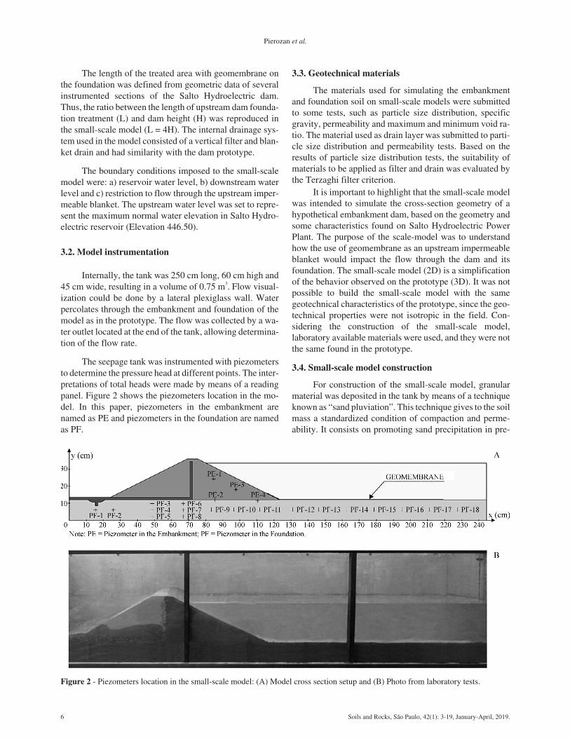
Internally, the tank was 250 cm long, 60 cm high and45 cm wide, resulting in a volume of 0.75 m3. Flow visual-ization could be done by a lateral plexiglass wall. Waterpercolates through the embankment and foundation of themodel as in the prototype. The flow was collected by a wa-ter outlet located at the end of the tank, allowing determina-tion of the flow rate.
The seepage tank was instrumented with piezometersto determine the pressure head at different points. The inter-pretations of total heads were made by means of a readingpanel. Figure 2 shows the piezometers location in the mo-del. In this paper, piezometers in the embankment arenamed as PE and piezometers in the foundation are namedas PF.
3.3. Geotechnical materials
The materials used for simulating the embankmentand foundation soil on small-scale models were submittedto some tests, such as particle size distribution, specificgravity, permeability and maximum and minimum void ra-tio. The material used as drain layer was submitted to parti-cle size distribution and permeability tests. Based on theresults of particle size distribution tests, the suitability ofmaterials to be applied as filter and drain was evaluated bythe Terzaghi filter criterion.
It is important to highlight that the small-scale modelwas intended to simulate the cross-section geometry of ahypothetical embankment dam, based on the geometry andsome characteristics found on Salto Hydroelectric PowerPlant. The purpose of the scale-model was to understandhow the use of geomembrane as an upstream impermeableblanket would impact the flow through the dam and itsfoundation. The small-scale model (2D) is a simplificationof the behavior observed on the prototype (3D). It was notpossible to build the small-scale model with the samegeotechnical characteristics of the prototype, since the geo-technical properties were not isotropic in the field. Con-sidering the construction of the small-scale model,laboratory available materials were used, and they were notthe same found in the prototype.
3.4. Small-scale model construction
For construction of the small-scale model, granularmaterial was deposited in the tank by means of a techniqueknown as “sand pluviation”. This technique gives to the soilmass a standardized condition of compaction and perme-ability. It consists on promoting sand precipitation in pre-
6 Soils and Rocks, São Paulo, 42(1): 3-19, January-April, 2019.
Pierozan et al.
Figure 2 - Piezometers location in the small-scale model: (A) Model cross section setup and (B) Photo from laboratory tests.
established conditions, in order to obtain a material as ho-mogeneous as possible (Rad & Tumay, 1987; Brandon etal., 1991; Lo Presti et al., 1992).
The sand deposition flow rate was kept constant byusing 5 mm opening funnels. Because soil compaction alsodepends on the material falling height in this method, a cali-bration curve relating falling height and material relativedensity was obtained. Based on the curves relating the sandfall height with the obtained soil density, it was selected afall height equal to 12 cm, for both embankment and foun-dation materials in small-scale models. This fall height wasadopted once small variation of the density has been veri-fied for greater heights.
The dam slopes were drawn in internal faces of thetank walls to geometrically orientate the construction of thesmall-scale dam model, drainage system and foundation.Successive layers of gauze and paraffin were applied overthe dam upstream soil to represent the impermeable mem-brane. Figure 3 presents some photographs of the model as-sembly. Wooden sticks were placed temporarily within thevertical filter (Fig. 3 - B) as leveling references.
3.5. Small-scale model simulations
Three distinct scenarios were simulated, allowing toevaluate the effect of an upstream impermeable membraneover the dam: a) no foundation treatment, b) use of geo-membrane upstream of the dam and c) use of damaged
geomembrane upstream of the dam. For each simulation,readings of total heads and percolation flow rates weremade. Figure 4 shows a small-scale model sketch.
In the model simulating the existence of defects onthe geomembrane, longitudinal openings were made in thesealing material upstream of the dam model to simulate de-fects that can occur during geomembrane installation and atthe end of the construction of the dam. The objective of thissimulation was to verify if the geomembrane sealing sys-tem would be able to maintain a minimum performanceeven with generalized failure. According to Nosko et al.(1996), this consideration is acceptable since most of theleaks occur during the procedure of covering the liner withsoil or stone, while other types of defects that could influ-ence the system proper behavior (e.g. seam failure betweengeomembrane rolls) may be identified and fixed at the sametime as the geomembrane installation quality control. Otherstudies (e.g. Rollin et al., 1999; Rollin et al., 2002; Rollin etal., 2004) also presented similar conclusions.
3.6. Results of small-scale seepage modelling
The geometric characteristics of the model are sum-marized in Table 2 and illustrated in Fig. 5. It is important toobserve that the dimensions adopted on the small-scalemodel were not exactly the same from Salto Hydroelectric
Soils and Rocks, São Paulo, 42(1): 3-19, January-April, 2019. 7
Geomembrane as an Upstream Impermeable Blanket of Embankment Dams - Laboratory and Numerical Study
Figure 3 - Construction of the small-scale model: (A) Drainageblanket and foundation soil, (B) Vertical filter, and (C) Imperme-able layer (Pierozan, 2014).
Downstream water outlet: 10 cmabove the tank bottom;
Geomembrane length (L) 96 cm (L = 4H).
Dam, once five sections were analyzed from the prototypeand just one section was analyzed in the small-scale model.
The results of the characterization tests, maximumand minimum void ratio and permeability of materials arepresented in Table 3. Based on grain size distribution cur-ves of the materials, their suitability for using in filtrationand drainage was verified.
Figure 6 shows the total head values obtained on thesection of the small-scale models. The piezometers were di-vided into 3 arrangements to simplify the analysis of the re-sults, considering that the arrangements are referring to thesame cross-section of the dam and analyzing a distinct setof piezometers.
According to Fig. 6, the presence of nondamagedgeomembrane upstream of the dam model reduced the totalflow through the embankment and foundation by approxi-
8 Soils and Rocks, São Paulo, 42(1): 3-19, January-April, 2019.
Pierozan et al.
Figure 5 - Dimensions of the small-scale model.
Figure 6 - Total hydraulic head obtained in tests with small-scale models.
Table 3 - Results of laboratory tests on material used on small-scale models.
Test Material
Foundation Dam Drain
Water content duringconstruction (%)
0.25 0.56 0.11
Specific gravity of solids 2.656 2.643 Notdetermined
Maximum void ratio 0.672 0.762 Notdetermined
Minimum void ratio 0.484 0.535 Notdetermined
Permeability (cm/s) 1 x 10⁻² 2 x 10⁻⁴ 5 x 100
mately 46%. On the other hand, the presence of a geomem-brane with defects reduced the water flow by only 8% whencomparing to the scenario without treatment.
Based on the results obtained in Arrangement 1(Fig. 6), the presence of geomembrane upstream of the dammodel leads to lower total heads. It can also be observedthat the reduction of the hydraulic heads occurs primarilyupstream from the chimney drain. The presence of defectsleads to a lower efficiency of the foundation treatment.
The foundation treatment with upstream imperme-able blanket had little influence on hydraulic heads over thedam embankment material, as shown in Arrangement 2. Onthe other hand, some influence can be noticed in the hy-draulic heads at the interface between the dam embankmentand foundation materials, as shown in Arrangement 3 (PE-2 and PE-4).
4. Numerical Analysis
Based on the results of the small-scale models, a hy-pothetical case with the same characteristics as the labora-tory model has been simulated, in prototype dimensions.SEEP/W® software (GEO-SLOPE, 2012) was used to per-form numerical analyses. This software provides two-dimensional analysis of groundwater flow within porousmaterials.
The following assumptions were admitted for the nu-merical analysis:
a) Geometric characteristics: The geometry of thedam and its foundation corresponded to that assumed in thesmall-scale models, except for scale and unit width(Width = 1 m). Table 4 presents the main geometric charac-teristics considered in the numerical analysis.
b) Saturated steady-state flow, governed by Darcy’sLaw. This assumption corresponds to a constant flow rateand volumetric water content at any position below the wa-ter table. The unsaturated flow at the downstream side wasdisregarded in the simulations. The seepage flow rate col-
lected by the drainage system was measured in two sec-tions: one between the vertical drain and the upstream blan-ket of the embankment, corresponding to the flow throughthe embankment (Section A-A’, Fig. 7-A), and another be-tween the horizontal drain and the foundation, correspond-ing to the flow through the foundation (Section B-B’, Fig.7-A). The sum of the two contributions resulted in the totalflow;
c) Boundary conditions: The adopted boundary con-ditions were (Fig. 7-B) a) total head equal to 33 m in the res-ervoir (12 m of foundation thickness plus 24 m of damheight, minus 3 m for the free board) and b) pressure headequal to atmospheric pressure in the vertical filter and in theblanket drain. These boundary conditions are reasonablesince the unsaturated flow did not represent a considerableamount of the total flow, according to previous simulations(Pierozan, 2014). For this reason, the unsaturated flow wasnot considered when dealing with the numerical model. Inthe geomembrane region, no boundary condition was ap-plied, in other words, the geomembrane was considered im-permeable.
d) Material properties: The hydraulic conductivity ofthe foundation was equal to 1 x 10⁻² cm/s and the hydraulicconductivity of the embankment was equal to 2 x 10⁻⁴ cm/svertically and 1 x 10⁻³ cm/s horizontally. These values havebeen adopted the same as for the small-scale tests Also, it
Soils and Rocks, São Paulo, 42(1): 3-19, January-April, 2019. 9
Geomembrane as an Upstream Impermeable Blanket of Embankment Dams - Laboratory and Numerical Study
Table 4 - Numerical model geometric characteristics.
Figure 7 - Numerical model: (A) Seepage flow rate collected by the drainage system and (B) Boundary conditions of the numericalmodel.
was considered that the embankment material had hydrau-lic conductivity in horizontal direction 5 times greater thanin vertical direction, which is the ratio found from labora-tory tests on undisturbed samples of the Salto Dam em-bankment.
Once calibrated with appropriate parameters fromphysical and experimental data, the numerical analysiscould simulate several not physically evaluated conditionsto study some hypothetical cases with different boundaryconditions. The behavior of the flow throughout the em-bankment dam and its foundation was evaluated in terms offlow rates, pressure heads and hydraulic gradients.
4.1. Validation and calibration
For the case with no geomembrane foundation treat-ment, the obtained flow rates were slightly higher thanthose obtained by the physical model. For anisotropy of thedam equal to 1, the predicted percolation flow rate has been3% higher than the value obtained for the small-scalemodel. For anisotropy of the dam equal to 5, this differencewas 16% and for anisotropy equal to 10, the difference was33%.
The numerical analyses with geomembrane treatmentalso obtained flow rates higher than those obtained in thephysical model. In this case, for anisotropy of the damequal to 1, the predicted percolation flow rate was 10%higher than the value obtained for the small-scale model.For anisotropy equal to 5, this difference was 33% and, foranisotropy equal to 10, 62%.
The predicted values of hydraulic head were similarto those measured in the small-scale models (Fig. 6), withslight variations relative to the anisotropy coefficients.
According to the numerical analyses with no geo-membrane foundation treatment, the differences betweenthe predicted pressure heads in relation to the small-scaletests (Fig. 6), within the dam foundation for the piezo-meters PF-12, PF-13, PF-14, PF-15, PF-16, PF-17 andPF-18 varied between zero and 1% for the studied aniso-tropy coefficients. For the dam foundation in the location ofpiezometers PF-1, PF-2, PF-3, PF-4 and PF-5, the predic-tions have shown a difference between -30% and -8%, oncethe chimney drain highly influences this area. However,this variation is considered small for engineering practice.On the other hand, for the piezometers PF-6, PF-7, PF-8,PF-9, PF-10 and PF-11, this difference has ranged between-11% and 1%. Finally, for the embankment dam in the loca-tion of piezometers PE-1, PE-2, PE-3 and PE-4, this differ-ence has ranged between -11% and -1%.
It was observed that the use of geomembrane as im-permeable blanket has resulted in a pressure head reductionmeasured under it at locations corresponding to piezo-meters PF-12, PF-13, PF-14, PF-15, PF-16, PF-17 andPF-18 of the small-scale model (Fig. 6). Predictions forthese piezometers and considering anisotropy of the damequal to 1 have presented differences of 12%, 11%, 9%,
9%, 5%, 5% and 2%, respectively, when comparing to thesmall-scale tests. On the other hand, applying an anisotropyof the dam equal to 5, the differences were 2%, 10%, 8%,9%, 5%, 5% and 2%, respectively. Lastly, for anisotropy ofthe dam equal to 10, the differences between predictionsand measurements have been 12%, 10%, 9%, 9%, 13%, 5%and 2%, respectively.
The use of geomembrane can also reduce the pressurehead in the dam foundation, according to the numericalanalysis. For piezometers PF-9, PF-10 and PF-11, this re-duction has ranged between 17% and 29%, which is similarto that observed in the small-scale model (Fig. 6). Addi-tionally, the numerical analyses also predicted a reductionof the hydraulic head between 4% and 8% for the piezo-meters PF-6, PF-7 and PF-8, located in the dam foundationbelow the vertical filter. For piezometers PF-6, PF-7, PF-8,PF-9, PF-10 and PF-11 and considering anisotropy of thedam equal to 1, the predicted pressure heads have reduced12%, 4%, 5%, 8%, 10% and 7%, respectively, when com-paring to the small-scale model. When considering the ani-sotropy of the dam equal to 5, the differences have been12%, 3%, 5%, 8%, 9% and 65%, respectively. Finally, thedifferences have been 12%, 3%, 5%, 7%, 8% and 6%, re-spectively, for anisotropy equal to 10.
The region within the embankment, corresponding topiezometers PE-1, PE-2, PE-3 and PE-4, presented a pres-sure head reduction between 20% and 45% due to the pres-ence of the geomembrane. For these piezometers, the simu-lations have diverged -10%, -10%, -8% and -9% whencomparing to the small-scale tests, respectively. However,when the anisotropy of the dam was considered equal to 5,the differences have been 13%, -8%, 2% and -8%, respec-tively. Following the results, the differences have been20%, -8%, 7% and -7%, respectively, for anisotropy of thedam equal to 10.
Based on these results, it can be inferred that the ani-sotropy coefficient from the embankment influences thepercolation flow rates and the pressure heads, for the casestudied. The anisotropy coefficient that leads to resultsclosest to the values obtained in small-scale modelling isequal to 1. However, it must be considered that compactedsoils in actual dams present anisotropy relative to perme-ability. For this reason and in accordance with Salto Damresults, the anisotropy coefficient adopted for the embank-ment in the numerical model was kh/kv = 5. This is accept-able, once in the field some factors cannot be simulated,such as heterogeneity.
4.2. Parametric analysis and results
After validation and calibration, parametric analyseswere performed to identify the influence of some factors onthe internal flow through dam. In these analyses, some pa-rameters were varied and others remained the same. In allanalyses the following independent variables were keptconstant: a) the dam geometry, b) the thickness of the foun-
10 Soils and Rocks, São Paulo, 42(1): 3-19, January-April, 2019.
Pierozan et al.
dation permeable soil and c) the hydraulic conductivity ofembankment and foundation. The following evaluationshave been made:
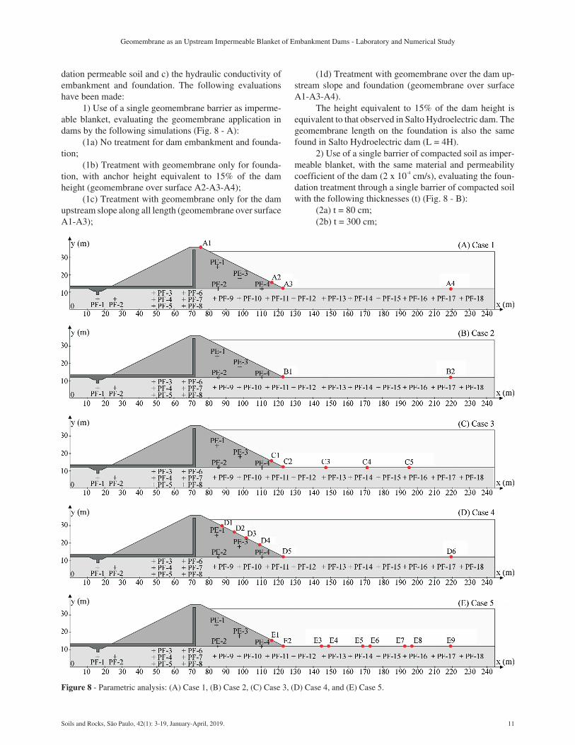
1) Use of a single geomembrane barrier as imperme-able blanket, evaluating the geomembrane application indams by the following simulations (Fig. 8 - A):
(1a) No treatment for dam embankment and founda-tion;
(1b) Treatment with geomembrane only for founda-tion, with anchor height equivalent to 15% of the damheight (geomembrane over surface A2-A3-A4);
(1c) Treatment with geomembrane only for the damupstream slope along all length (geomembrane over surfaceA1-A3);
(1d) Treatment with geomembrane over the dam up-stream slope and foundation (geomembrane over surfaceA1-A3-A4).
The height equivalent to 15% of the dam height isequivalent to that observed in Salto Hydroelectric dam. Thegeomembrane length on the foundation is also the samefound in Salto Hydroelectric dam (L = 4H).
2) Use of a single barrier of compacted soil as imper-meable blanket, with the same material and permeabilitycoefficient of the dam (2 x 10⁻⁴ cm/s), evaluating the foun-dation treatment through a single barrier of compacted soilwith the following thicknesses (t) (Fig. 8 - B):
(2a) t = 80 cm;(2b) t = 300 cm;
Soils and Rocks, São Paulo, 42(1): 3-19, January-April, 2019. 11
Geomembrane as an Upstream Impermeable Blanket of Embankment Dams - Laboratory and Numerical Study
Figure 8 - Parametric analysis: (A) Case 1, (B) Case 2, (C) Case 3, (D) Case 4, and (E) Case 5.
(2c) t = 600 cm.The foundation treatment length was the same con-
sidered for the geomembrane (L = 4H), over surface B1-B2.
3) Length of the upstream dam foundation treatment(without soil blanket), evaluating the geomembrane lengthon the foundation (L) in relation to the total height of thedam (H) (Fig. 8 - C):
(3a) L=H (geomembrane over surface C1-C2-C3);(3b) L = 2.H (geomembrane over surface C1-C2-C4);(3c) L = 3.H (geomembrane over surface C1-C2-C5).All the simulations considered the anchor height
equivalent to 15% of the dam height (surface C1-C2).4) Length of the geomembrane over the upstream
slope of the dam, evaluating the geomembrane anchorageheight (Ha) as a function of the total height of the dam (H)(Fig. 8 - D):
(4a) Ha = 30%.H (geomembrane over surface D4-D5-D6);
(4b) Ha = 45%.H (geomembrane over surface D3-D5-D6);
(4c) Ha = 60%.H (geomembrane over surface D2-D5-D6);
(4d) Ha = 75%.H (geomembrane over surfaceD1-D5-D6).
The foundation treatment length was considered con-stant and equal to L = 4H, over surface D5-D6.
5) Longitudinal defects in the geomembrane, simulat-ing a set of defects and evaluating the effect of an 80 cmthick compacted soil as a secondary barrier. Consideringthat the software used in the analysis supports only two-dimensional simulations, these defects were simulated as asingle longitudinal tear on the geomembrane, with unitwidth (1 m). The idea is to simulate a very adverse condi-tion related to problems that can occur in the field such asduring the placement of the cover soil over the geomem-brane, since this constructive stage may result in geomem-brane defects if not properly implemented. More reason-able parameters could be obtained with the use ofthree-dimensional modeling.
The following simulations were made (Fig. 8- E):(5a) Presence of one 4 m long defect at half the length
of the geomembrane, no secondary soil barrier (geomem-brane over surface E1-E2-E9, defect over surface E5-E6);
(5b) Presence of one 4 m long defect at half the lengthof the geomembrane, and secondary soil barrier (geomem-brane over surface E1-E2-E9, defect over surface E5-E6);
(5c) Presence of three 4 m long defects equallyspaced along the geomembrane, no secondary soil barrier(geomembrane over surface E1-E2-E9, defect over sur-faces E3-E4, E5-E6 and E7-E8);
(5d) Presence of three 4 m long defects equallyspaced along the geomembrane, and secondary soil barriergeomembrane over surface E1-E2-E9, defect over surfacesE3-E4, E5-E6 and E7-E8).
The results of parametric analyses are presented anddiscussed according to hydraulic head, flow rate and hy-draulic gradient, as follows.
4.2.1. Pressure head
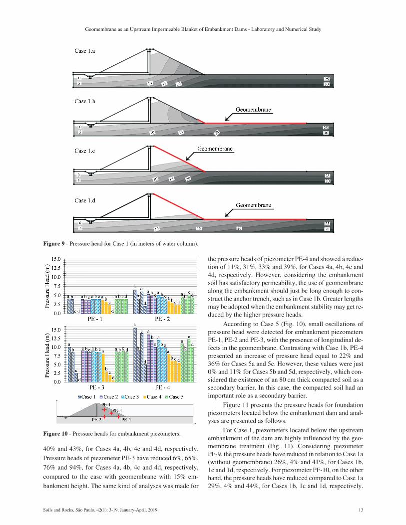
The pressure heads obtained by the analyses consid-ering or not the presence of the geomembrane (Case 1) areshown in Fig. 9. When geomembrane was used, the headswere significantly reduced, indicating that the geomem-brane caused the reduction of pressure head in the soil.Foundation treatment with geomembrane increased thedam safety, since a pressure head and water flow decreasewere observed.
The pressure heads measured in further simulationsare presented in relation to the piezometer locations(Fig. 9). This procedure was adopted to synthesize the eval-uated data. Slight variations were detected for piezometersPF-1 to PF-8, once they are installed in the dam foundationbelow the downstream embankment and are not suitable forevaluating the geomembrane performance.
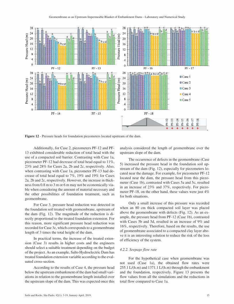
Figure 10 presents the pressure heads of the embank-ment piezometers and analyzes are presented as follows.
With the presence of the geomembrane (Case 1),based on the results (Fig. 9), it is possible to understand thatpressure heads are heavily influenced by the upstream em-bankment and foundation treatment with geomembrane. Ifthe design purpose is to reduce the pressure heads in theembankment to ensure dam stability, Case 1c has the bestcost-benefit. However, the installation of geomembraneover the upstream embankment may not be viable when theembankment has low hydraulic conductivity and the designpurpose of the geomembrane installation is to minimize theflow rates along the foundation soil. In this case, Case 1bhas the best cost-benefit. Case 1d may be the best solutionfor cases when both embankment and foundation have highhydraulic conductivity.
The use of a compacted soil barrier (Case 2) resultedin small pressure changes in the embankment, with excep-tion of piezometer PE-4, which is located near the anchortrench.
In relation to the study concerning the geomembranelength relative to the total height of the dam (Case 3), smallchanges in pressure head were detected for the embank-ment piezometers (Fig. 10), except for piezometer PE-4.For this reason, for the studied case, it is possible to con-clude that the length of the treatment does not heavily influ-ence the upstream embankment stability, as long as thepressure heads remain below projected levels.
According to the results of Case 4 (Fig. 10), the pres-sure heads within the embankment have reduced when thegeomembrane height along the slope increased. In relationto Case 1b, pressure heads of piezometer PE-1 have re-duced 3%, 15%, 38% and 100%, for Cases 4a, 4b, 4c and4d, respectively. Again, when comparing to Case 1b, pres-sure heads of piezometer PE-2 have reduced 13%, 25%,
12 Soils and Rocks, São Paulo, 42(1): 3-19, January-April, 2019.
Pierozan et al.
40% and 43%, for Cases 4a, 4b, 4c and 4d, respectively.
Pressure heads of piezometer PE-3 have reduced 6%, 65%,
76% and 94%, for Cases 4a, 4b, 4c and 4d, respectively,
compared to the case with geomembrane with 15% em-
bankment height. The same kind of analyses was made for
the pressure heads of piezometer PE-4 and showed a reduc-tion of 11%, 31%, 33% and 39%, for Cases 4a, 4b, 4c and4d, respectively. However, considering the embankmentsoil has satisfactory permeability, the use of geomembranealong the embankment should just be long enough to con-struct the anchor trench, such as in Case 1b. Greater lengthsmay be adopted when the embankment stability may get re-duced by the higher pressure heads.
According to Case 5 (Fig. 10), small oscillations ofpressure head were detected for embankment piezometersPE-1, PE-2 and PE-3, with the presence of longitudinal de-fects in the geomembrane. Contrasting with Case 1b, PE-4presented an increase of pressure head equal to 22% and36% for Cases 5a and 5c. However, these values were just0% and 11% for Cases 5b and 5d, respectively, which con-sidered the existence of an 80 cm thick compacted soil as asecondary barrier. In this case, the compacted soil had animportant role as a secondary barrier.
Figure 11 presents the pressure heads for foundationpiezometers located below the embankment dam and anal-yses are presented as follows.
For Case 1, piezometers located below the upstreamembankment of the dam are highly influenced by the geo-membrane treatment (Fig. 11). Considering piezometerPF-9, the pressure heads have reduced in relation to Case 1a(without geomembrane) 26%, 4% and 41%, for Cases 1b,1c and 1d, respectively. For piezometer PF-10, on the otherhand, the pressure heads have reduced compared to Case 1a29%, 4% and 44%, for Cases 1b, 1c and 1d, respectively.
Soils and Rocks, São Paulo, 42(1): 3-19, January-April, 2019. 13
Geomembrane as an Upstream Impermeable Blanket of Embankment Dams - Laboratory and Numerical Study
Figure 9 - Pressure head for Case 1 (in meters of water column).
Figure 10 - Pressure heads for embankment piezometers.
Piezometer PF-11 presented reduction of pressure heads, inrelation to Case 1a, equal to 36%, 5% and 48%, for Cases1b, 1c and 1d, respectively. For this reason, Cases 1b and 1dhave better cost-benefit when the geomembrane purpose isto reduce pressure head in the foundation.
Considering the use of a compacted soil layer (Case2), variations in pressure heads were detected for piezo-meters located below the upstream embankment of the dam(Fig. 11), however the effect of the geomembrane in pres-sure head reduction is lower than with the use of geomem-brane (Case 1b).
The pressure head for foundation piezometers locatedbelow the upstream embankment of the dam (Fig. 11) pre-sented small changes for piezometer PF-9 and more consid-erable changes for PF-10 and PF-11, which are locatednearest to the treated area. In relation to Case 3a, which cor-responds to a geomembrane length equal to the total heightof the dam, the maximum reduction of pressure head (Case3c) was 6%, 14% and 17% for piezometers PF-9, PF-10 andPF-11, respectively.
According to the results of Case 4, the pressure headwithin the foundation soil upstream of the dam had smallvariations in relation to the geomembrane length installedover the upstream slope of the dam.
For Case 5, an increase of pressure head was observedfor foundation piezometers located below the upstream em-bankment of the dam (Fig. 11), when comparing to Case 1b.The increase of pressure head is a consequence of the flowrate increment on foundation soil below the dam. However,Cases 5b and 5d presented lower increase of pressure head,once an 80 cm thick compacted soil was considered as sec-ondary barrier, with the same hydraulic conductivity of thedam.
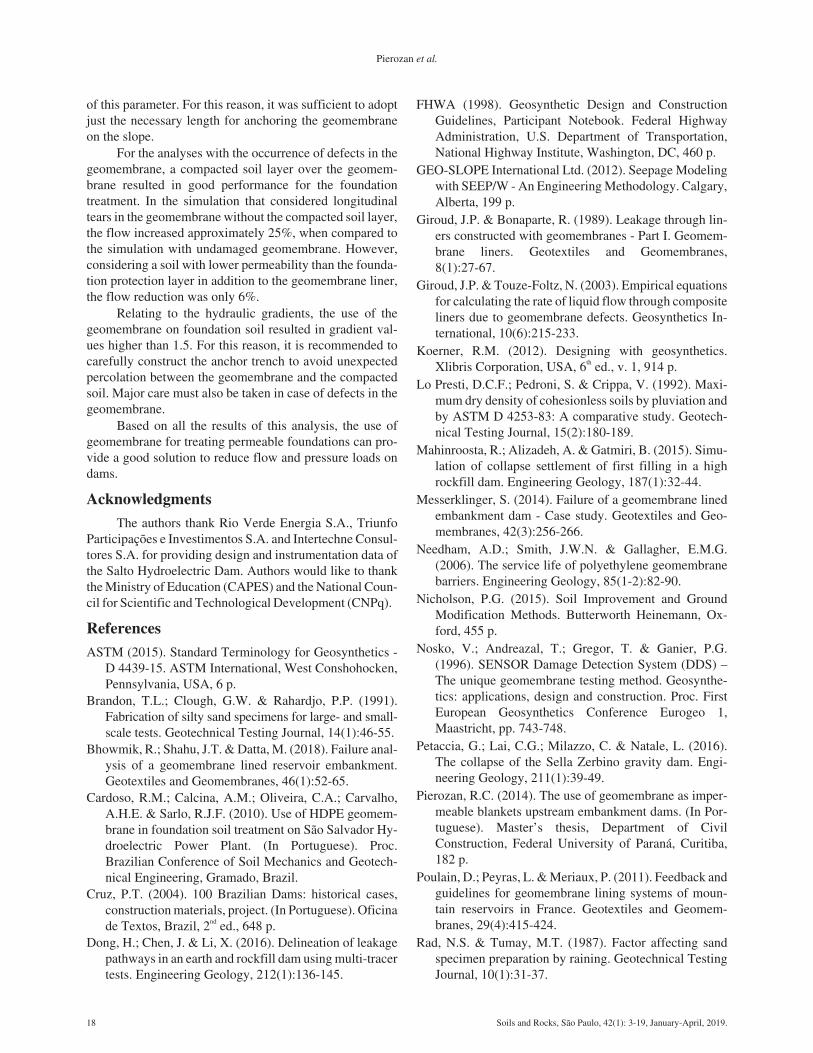
Figure 12 presents the pressure head for foundationpiezometers located upstream of the dam, and analyses arepresented as follows.
Considering Case 1, pressure heads from piezometersPF-12 to PF-18 (Fig. 12) have reduced with the installation
of geomembrane along the foundation (Cases 1b and 1d).The reduction of pressure head was equal to 39%, 33%,27%, 20%, 15%, 9% and 4% for piezometers PF-12, PF-13,PF-14, PF-15, PF-16, PF-17 and PF-18, respectively, forCase 1b in relation to Case 1a. On the other hand, the reduc-tion of pressure head was equal to 49%, 39%, 33%, 26%,19%, 10% and 4% for piezometers PF-12, PF-13, PF-14,PF-15, PF-16, PF-17 and PF-18, respectively, when ana-lyzing the difference between Case 1d and Case 1a. For thisreason, it may be concluded that the geomembrane effect isgreater for the foundation area near the dam and lower forthe area located more distantly. Small variations were de-tected in the foundation soil for Case 1c.
Regarding the use of compacted soil barrier (Case 2),the reduction of pressure in the foundation is lower in mag-nitude than that observed for geomembrane application, in-dicating that the use of a single compacted soil barrier isless effective than the use of geomembrane for the evalu-ated case, even with high values of thickness (6 m). It mustbe considered that the studied soil liner has the same perme-ability of the embankment dam (2 x 10⁻⁴ cm/s) and better re-sults might be achieved with the use of soils with lowerpermeability. However, even when geomembranes are ap-plied, a protective layer is normally recommended for geo-membrane protection. In the specific case of this research, acompacted soil barrier was used with the purpose of actingas a watertight defense if the geomembrane is subjected todamage, also cooperating in the geomembrane protection.It is important to highlight that thick layers of polypropy-lene geotextile might be used with the purpose of protectingthe geomembrane rather than compacted soil layers, sincethe installation of the synthetic layers may lead to lowerrisks of damaging the geomembrane. Besides, some re-searchers (e.g. Touze-Foltz, 2009) have shown that whenthe compacted soil over the geomembrane becomes satu-rated and is subjected to an applied load, the flow ratethrough the geomembrane defects may increase.
14 Soils and Rocks, São Paulo, 42(1): 3-19, January-April, 2019.
Pierozan et al.
Figure 11 - Pressure heads for foundation piezometers located below the upstream embankment of the dam.
Additionally, for Case 2, piezometers PF-12 and PF-13 exhibited considerable reduction of total head with theuse of a compacted soil barrier. Contrasting with Case 1a,piezometer PF-12 had decrease of total head equal to 11%,23% and 28% for Cases 2a, 2b and 2c, respectively. Also,when contrasting with Case 1a, piezometer PF-13 had de-crease of total head equal to 7%, 19% and 19% for Cases2a, 2b and 2c, respectively. However, the increase in thick-ness from 0.8 m to 3 m or 6 m may not be economically via-ble when considering the amount of material necessary andthe other possibilities of foundation treatment, such asgeomembrane.
For Case 3, pressure head reduction was detected inthe foundation soil treated with geomembrane, upstream ofthe dam (Fig. 12). The magnitude of the reduction is di-rectly proportional to the treated foundation extension. Forthis reason, more significant pressure head reduction wasrecorded for Case 3c, which corresponds to a geomembranelength of 3 times the total height of the dam.
In practical terms, the increase of the treated exten-sion (Case 3) results in higher costs and the engineersshould select a suitable treatment depending on the budgetof the project. As an example, Salto Hydroelectric Dam hastreated foundation extension variable according to the eval-uated cross-section.
According to the results of Case 4, the pressure headbelow the upstream embankment of the dam had small vari-ations in relation to the geomembrane length installed overthe upstream slope of the dam. This was expected once this
analysis considered the length of geomembrane over theupstream slope of the dam.
The occurrence of defects in the geomembrane (Case5) increased the pressure head in the foundation soil up-stream of the dam (Fig. 12), especially for piezometers lo-cated near the damage. For example, for piezometer PF-12located near the dam, the pressure head from this piezo-meter (Case 1b), contrasted with Cases 5a and 5c, resultedin an increase of 23% and 37%, respectively. For piezo-meter PF-18, on the other hand, these values were just 4%for both situations.
Only a small increase of this pressure was recordedwhen an 80 cm thick compacted soil layer was placedabove the geomembrane with defects (Fig. 12). As an ex-ample, the pressure head from PF-12 (Case 1b), contrastedwith Cases 5b and 5d, resulted in an increase of 9% and16%, respectively. Therefore, based on the results, the useof geomembrane associated to a compacted clay layer abo-ve it is an interesting solution to reduce the risk of the lossof efficiency of the system.
4.2.2. Seepage flow rate
For the hypothetical case when geomembrane wasnot used (Case 1a), the obtained flow rates were255.1 L/(h.m) and 1371.1 L/(h.m) through the embankmentand the foundation, respectively. Figure 13 presents theflow values from all the simulations and the reductions intotal flow compared to Case 1a.
Soils and Rocks, São Paulo, 42(1): 3-19, January-April, 2019. 15
Geomembrane as an Upstream Impermeable Blanket of Embankment Dams - Laboratory and Numerical Study
Figure 12 - Pressure heads for foundation piezometers located upstream of the dam.
Flow reduction in the embankment was detected evenwhen geomembrane was applied over the upstream slope ofthe dam with just the necessary length for anchoring it,making them work together. Since the permeability of thefoundation is 50 times higher than the permeability of theembankment, most of the percolation occurred through thesoil foundation, justifying the use of geomembrane only onpermeable foundation soil (Case 1) for the studied case.
Predicted values considering only the use of com-pacted soil as a barrier (Case 2) showed that the flow rateswere greater than the ones with the use of geomembrane.For 0.8 m thick soil layer, the total flow rate has increased43%, whereas for 3 and 6 m thick layers, the increase wasequal to 26% and 14%, respectively, when compared toCase 1b. Therefore, even considering that the compactedsoil layer has no cracks, its efficiency is lower when com-pared to the use of geomembrane without defects for thestudied case. For this reason, the construction of thick lay-ers of compacted soil might not be economically feasiblewhen compared to solutions with geomembranes and eachcase must be evaluated by the engineers.
Based on the simulations that considered the variationof the geomembrane length (Case 3), it was found that theseepage flow through the foundation depends on the lengthof the water percolation path. Although there is a reductionin flow through the embankment, its magnitude is smallwhen compared to the flow through the foundation.
According to the obtained results from numericalanalyses that considered the length of geomembrane overthe upstream slope of the dam (Case 4), when the length in-creases the flow rate through the embankment decreases.However, the decrease in total flow is small, because mostof the flow occurred through the foundation and the geo-membrane is covering most of it. For this reason, it is suffi-cient to adopt just the necessary length for anchoring thegeomembrane on the slope.
The obtained seepage flow rates considering the exis-tence of one longitudinal tear showed that if there is not acompacted soil layer over the geomembrane (Case 5a), thetotal flow increases approximately 25% when compared
with the geomembrane without defect (Case 1b). However,if an 80 cm thick protective soil layer is placed over thegeomembrane (Case 5b), the flow rate increases only 6% incomparison with the case of geomembrane without defect(Case 1b). Predicted values of total flow, when three de-fects were considered in the geomembrane, indicated thatthe flow rate increase was approximately 32% (Case 5c)higher than that obtained for the geomembrane without de-fect (Case 1b), however this value was only 14% consider-ing the presence of a protection layer (Case 5d). Thus, thepresence of a layer of lower permeability than the founda-tion above the geomembrane is of great relevance for theproper performance of the system.
4.2.3. Hydraulic gradient
According to the results presented for Case 1, the hy-draulic gradients in most of the embankment were between0.8 and 1 for the analyses without the presence of geomem-brane. Considering the use of geomembrane on foundationsoil, the hydraulic gradient in the embankment, specificallynear the anchor trench area, reached values above 1.5, asshown in Fig. 14 (A). For this reason, the anchorage areamust be carefully constructed to avoid unexpected percola-tion between the geomembrane and the compacted soil.
In Case 2, the hydraulic gradients were found be-tween 0.5 and 1 for most of the embankment for the casewhen an 80 cm thick compacted soil liner was employed. Inthe simulations considering soil liner 3 and 6 m thick, gra-dients in the embankment were between 0.8 and 1.2. Highhydraulic gradients were observed near the connection withthe embankment dam, with values ranging between 1.4 and1.8, as shown in Fig. 14 (B), which suggests that the an-chorage region between the embankment dam and the com-pacted soil liner must have high execution process control.
The hydraulic gradients observed in Case 3 rangedbetween 0.8 and 1.0 in most of the embankment, when ageomembrane with length L = H = 24 m was used. Forhigher lengths, the hydraulic gradients were greater, withvalues between 1 and 1.5 in the embankment, with greatervalues near the anchor trench area. In all the studied cases,
16 Soils and Rocks, São Paulo, 42(1): 3-19, January-April, 2019.
Pierozan et al.
Figure 13 - Flow rate reduction in relation to all the studies.
hydraulic gradients lower than 0.5 were observed in thefoundation.
Regarding Case 4, it was observed that the installa-tion of the geomembrane over the upstream slope of thedam reduced the hydraulic gradient in the embankment.However, the flow through the embankment corresponds toa small portion of the total flow collected by the drainagesystem. High hydraulic gradients in anchor trench areas,with values greater than 1.5, were observed in all analyses,with small differences due to different lengths.
The presence of defects in the geomembrane (evalu-ated in Case 5) led to the increase of hydraulic gradient inthe soil foundation when compared to the case of the geo-membrane with no defects. However, the values were be-low 0.5. Particularly in the damaged areas, high hydraulicgradients were found, which can contribute to the forma-tion of percolation paths below the geomembrane. This isconfirmed by the high values of pressure head of somepiezometers below the defects, shown in the last section(Fig. 6).
5. Conclusions
This paper presented an experimental and numericalstudy of the performance of HDPE geomembrane as an im-permeable blanket installed upstream of embankmentdams. Data from the Brazilian Salto Hydroelectric PowerPlant contributed to the development of a small-scale seep-age model and the numerical modelling. After the labora-tory tests, some parameters were calibrated and somenumerical analyses of those tests have been performed. Ad-ditionally, some hypothetical conditions varying the pres-ence of defects in the geomembrane, the impermeableblanket thickness and the length of the geomembrane werecarried out.
For the small scale model, the obtained results indi-cated that the geomembrane impermeable blanket in-creased the percolation path through the dam soil founda-tion, reducing the pressure head in both embankment andfoundation, as well as the flow collected by the drainagesystem. The higher reduction in pressure head occurred inthe dam foundation, below the geomembrane and in thedam embankment upstream of the vertical filter. At thedownstream side of the dam, on the other hand, a smallvariation of pressure head was observed. It indicates thatthe flow in the downstream side is controlled by the chim-
ney drain. The tests also have shown that if the appliedgeomembrane has damage, the total flow collected by thedrainage system and the pressure heads are similar to thoseobserved in the test with no geomembrane.
Based on the results of the scaled and the numericalmodel, it can be inferred that the anisotropy coefficientfrom the embankment influences the percolation flow ratesfor the case studied. The anisotropy coefficient that leads toresults closest to the values obtained in small-scale model-ling is equal to 1. However, it must be considered that com-pacted soils in actual dams present anisotropy relative topermeability. For this reason and in accordance with SaltoDam results, the anisotropy coefficient adopted for the em-bankment in the numerical model was kh/kv = 5.
Regarding the use of impermeable blanket of com-pacted soil as a single barrier with a horizontal permeabilityof 1 x 10⁻³ cm/s and vertical permeability of 2 x 10⁻⁴ cm/s(same material of dam), even considering it without cracks,the seepage reduction was not as significant as that foundwhen geomembranes were used. Even for a 6 m thick layer,the performance of compacted soil was worse than that ob-tained by using geomembrane. The flow rates were greaterthan those calculated by software simulation with the use ofgeomembrane. Thus, even considering that the compactedsoil layer has no cracks, its efficiency in some cases islower when compared to the use of geomembrane withoutdamage for the case studied.
For the analyses that considered the length of thegeomembrane, pressure head reduction was detected in thefoundation soil treated, upstream of the dam. Thus, themagnitude of the reduction is dependent on the treatedfoundation extension. It was also found that the seepageflow through the foundation depends on the length of thewater percolation path.
The analyses considering the length of the geomem-brane over the upstream slope of the dam have shown thatthe pressure head in the foundation soil had small variationin relation to the geomembrane length installed over the up-stream slope of the dam, once most of the flow occurredthrough the foundation. However, the pressure head withinthe embankment have reduced when the geomembranelength along the upstream slope increased. Considering thatmost of the total flow occurred through the foundation, in-creasing the length of the geomembrane over the upstreamslope of the dam is not effective for reducing the magnitude
Soils and Rocks, São Paulo, 42(1): 3-19, January-April, 2019. 17
Geomembrane as an Upstream Impermeable Blanket of Embankment Dams - Laboratory and Numerical Study
Figure 14 - Hydraulic gradients in the embankment dam: (A) Case 1b, and (B) Case 2a.
of this parameter. For this reason, it was sufficient to adoptjust the necessary length for anchoring the geomembraneon the slope.
For the analyses with the occurrence of defects in thegeomembrane, a compacted soil layer over the geomem-brane resulted in good performance for the foundationtreatment. In the simulation that considered longitudinaltears in the geomembrane without the compacted soil layer,the flow increased approximately 25%, when compared tothe simulation with undamaged geomembrane. However,considering a soil with lower permeability than the founda-tion protection layer in addition to the geomembrane liner,the flow reduction was only 6%.
Relating to the hydraulic gradients, the use of thegeomembrane on foundation soil resulted in gradient val-ues higher than 1.5. For this reason, it is recommended tocarefully construct the anchor trench to avoid unexpectedpercolation between the geomembrane and the compactedsoil. Major care must also be taken in case of defects in thegeomembrane.
Based on all the results of this analysis, the use ofgeomembrane for treating permeable foundations can pro-vide a good solution to reduce flow and pressure loads ondams.
AcknowledgmentsThe authors thank Rio Verde Energia S.A., Triunfo
Participações e Investimentos S.A. and Intertechne Consul-tores S.A. for providing design and instrumentation data ofthe Salto Hydroelectric Dam. Authors would like to thankthe Ministry of Education (CAPES) and the National Coun-cil for Scientific and Technological Development (CNPq).
ReferencesASTM (2015). Standard Terminology for Geosynthetics -
D 4439-15. ASTM International, West Conshohocken,Pennsylvania, USA, 6 p.
Brandon, T.L.; Clough, G.W. & Rahardjo, P.P. (1991).Fabrication of silty sand specimens for large- and small-scale tests. Geotechnical Testing Journal, 14(1):46-55.
Bhowmik, R.; Shahu, J.T. & Datta, M. (2018). Failure anal-ysis of a geomembrane lined reservoir embankment.Geotextiles and Geomembranes, 46(1):52-65.
Cardoso, R.M.; Calcina, A.M.; Oliveira, C.A.; Carvalho,A.H.E. & Sarlo, R.J.F. (2010). Use of HDPE geomem-brane in foundation soil treatment on São Salvador Hy-droelectric Power Plant. (In Portuguese). Proc.Brazilian Conference of Soil Mechanics and Geotech-nical Engineering, Gramado, Brazil.
Cruz, P.T. (2004). 100 Brazilian Dams: historical cases,construction materials, project. (In Portuguese). Oficinade Textos, Brazil, 2nd ed., 648 p.
Dong, H.; Chen, J. & Li, X. (2016). Delineation of leakagepathways in an earth and rockfill dam using multi-tracertests. Engineering Geology, 212(1):136-145.
FHWA (1998). Geosynthetic Design and ConstructionGuidelines, Participant Notebook. Federal HighwayAdministration, U.S. Department of Transportation,National Highway Institute, Washington, DC, 460 p.
GEO-SLOPE International Ltd. (2012). Seepage Modelingwith SEEP/W - An Engineering Methodology. Calgary,Alberta, 199 p.
Giroud, J.P. & Bonaparte, R. (1989). Leakage through lin-ers constructed with geomembranes - Part I. Geomem-brane liners. Geotextiles and Geomembranes,8(1):27-67.
Giroud, J.P. & Touze-Foltz, N. (2003). Empirical equationsfor calculating the rate of liquid flow through compositeliners due to geomembrane defects. Geosynthetics In-ternational, 10(6):215-233.
Koerner, R.M. (2012). Designing with geosynthetics.Xlibris Corporation, USA, 6th ed., v. 1, 914 p.
Lo Presti, D.C.F.; Pedroni, S. & Crippa, V. (1992). Maxi-mum dry density of cohesionless soils by pluviation andby ASTM D 4253-83: A comparative study. Geotech-nical Testing Journal, 15(2):180-189.
Mahinroosta, R.; Alizadeh, A. & Gatmiri, B. (2015). Simu-lation of collapse settlement of first filling in a highrockfill dam. Engineering Geology, 187(1):32-44.
Messerklinger, S. (2014). Failure of a geomembrane linedembankment dam - Case study. Geotextiles and Geo-membranes, 42(3):256-266.
Needham, A.D.; Smith, J.W.N. & Gallagher, E.M.G.(2006). The service life of polyethylene geomembranebarriers. Engineering Geology, 85(1-2):82-90.
Nicholson, P.G. (2015). Soil Improvement and GroundModification Methods. Butterworth Heinemann, Ox-ford, 455 p.
Nosko, V.; Andreazal, T.; Gregor, T. & Ganier, P.G.(1996). SENSOR Damage Detection System (DDS) –The unique geomembrane testing method. Geosynthe-tics: applications, design and construction. Proc. FirstEuropean Geosynthetics Conference Eurogeo 1,Maastricht, pp. 743-748.
Petaccia, G.; Lai, C.G.; Milazzo, C. & Natale, L. (2016).The collapse of the Sella Zerbino gravity dam. Engi-neering Geology, 211(1):39-49.
Pierozan, R.C. (2014). The use of geomembrane as imper-meable blankets upstream embankment dams. (In Por-tuguese). Master’s thesis, Department of CivilConstruction, Federal University of Paraná, Curitiba,182 p.
Poulain, D.; Peyras, L. & Meriaux, P. (2011). Feedback andguidelines for geomembrane lining systems of moun-tain reservoirs in France. Geotextiles and Geomem-branes, 29(4):415-424.
18 Soils and Rocks, São Paulo, 42(1): 3-19, January-April, 2019.
Pierozan et al.
Rollin, A.L.; Marcotte, M.; Jacquelin, T. & Chaput, L.(1999). Leak location in exposed geomembrane linersusing an electrical leak detection technique. Proc. Geo-synthetics’99, Boston, United States of America, pp.615-626.
Rollin, A.L.; Marcotte, M.; Chaput, L. & Caquel, F. (2002).Lessons learned from geo-electrical leaks surveys.Proc. Geosynthetics 2002, Nice, France, pp. 527-530.
Rollin, A.L.; Jacquelin, T.; Forget, B. & Saunier, P. (2004).A guide to detect leaks on installed geomembranes.Proc. EuroGEO, Munich, Germany, pp. 235-240.
Scuero, A.M. & Vaschetti, G.L. (2004). Watertightness andSafety of Dams Using Geomembranes. Long-TermBenefits and Performance of Dams. Thomas Telford,London, 15 p.
Shukla, S.K. (2002). Geosynthetic Applications – GeneralAspects and Selected Case Studies. Handbook of Geo-synthetic Engineering. Department of Civil Engi-neering, Harcourt Butler Technological Institute,Kanpur, 422 p.
Tao, T.; Yan, J.; Tao, X.; Fu, F.F. & Zhou, H. (1996). Ap-plication of geotextile/geomembrane composite linerfor infiltration prevention in Xiaolingtou rock-fill dam.Geosynthetics International, 3(1):125-136.
Touze-Foltz, N. (2009). Evaluation of flow in lining sys-tems of Brazilian landfills. Version 4. Unité HBAN,Cedex, France, 18 p.
Whitfield, B.L. (1996). Geomembrane application for anRCC dam. Geotextiles and Geomembranes,14(5-6):253-264.
Wu, W.; Wang, X.T. & Aschauer, F.F. (2008). Investiga-tion on failure of a geosynthetic lined reservoir. Geo-textiles and Geomembranes, 26(4):363-370.
Soils and Rocks, São Paulo, 42(1): 3-19, January-April, 2019. 19
Geomembrane as an Upstream Impermeable Blanket of Embankment Dams - Laboratory and Numerical Study