COMPUTER GRAPHICS AND IMAGE PROCESSING 19, 129-147 (1982) Geometric Modeling Using Octree Encoding DONALDMEAGHER* Rensselaer Polytechnic Institute, Troy, New York 12181 Received June 19,198 1 A geometric modeling technique called Octree Encoding is presented. Arbitrary 3-D objects can be represented to any specified resolution in a hierarchical I-ary tree structure or “octree.” Objects may be concave or convex, have holes (including interior holes), consist of disjoint parts, and possess sculptured (i.e., “free-form”) surfaces. The memory required for representa- tion and manipulation is on the order of the surface area of the object. A complexity metric is proposed based on the number of nodes in an object’s tree representation. Efficient (linear time) algorithms have been developed for the Boolean operations (union, intersection and difference), geometric operations (translation, scaling and rotation), N-dimensional interference detection, and display from any point in space with hidden surfaces removed. The algorithms require neither floating-point operations, integer multiplications, nor integer divisions. In addition, many independent sets of very simple calculations are typically generated, allowing implementation over many inexpensive high-bandwidth processors operating in parallel. Real time analysis and manipulation of highly complex situations thus becomes possible. I. INTRODUCTION Advances in many areas of technology are currently being impeded because effective and practical three-dimensional object representation schemes and associ- ated algorithms for manipulation, analysis, and display are not available. Generally used techniques have a limited range of applicability because of shortcomings in two major areas. First, representation capabilities are not sufficiently robust to easily handle the object complexities required in a realistic environment. Second, manipu- lation and display algorithms performing functions such as interference detection (two or more objects occupying the same region of space) and hidden surface removal (necessary for realistic display) require extremely large numbers of calcula- tions in practical situations. They usually exhibit exponential (often quadratic) growth in the number and complexity of the objects. It is not believed that near-term progress in hardware technology will render such schemes practical for the vast majority of potential applications. Much more efficient data structures and algo- rithms which take advantage of current hardware trends are needed. Existing 3-D representation schemes have been divided into the following six categories by Voelcker and Requicha [ 1, 281: (1) Primitive Instancing-Families of objects are defined parametricahy. A shape type and a limited set of parameter values specifies an object. (2) Spatial Enumeration-An object is represented by a list of the cubical spatial cells which it occupies. (3) Cell Decomposition-A generalized form of spatial enumeration in which the disjoint cells are not necessarily cubical or even identical. *Current address: Phoenix Data Systems, Albany, New York 12205. 129 Ol46-664X/82/060129-19$02.00/0 Copyright @ 1982 by Academic Press, Inc. All tights of reproduction in any form resewed.
Transcript
COMPUTER GRAPHICS AND IMAGE PROCESSING 19, 129-147 (1982)
Geometric Modeling Using Octree Encoding
DONALDMEAGHER*
Rensselaer Polytechnic Institute, Troy, New York 12181
Received June 19,198 1
A geometric modeling technique called Octree Encoding is presented. Arbitrary 3-D objects can be represented to any specified resolution in a hierarchical I-ary tree structure or “octree.” Objects may be concave or convex, have holes (including interior holes), consist of disjoint parts, and possess sculptured (i.e., “free-form”) surfaces. The memory required for representa- tion and manipulation is on the order of the surface area of the object. A complexity metric is proposed based on the number of nodes in an object’s tree representation. Efficient (linear time) algorithms have been developed for the Boolean operations (union, intersection and difference), geometric operations (translation, scaling and rotation), N-dimensional interference detection, and display from any point in space with hidden surfaces removed. The algorithms require neither floating-point operations, integer multiplications, nor integer divisions. In addition, many independent sets of very simple calculations are typically generated, allowing implementation over many inexpensive high-bandwidth processors operating in parallel. Real time analysis and manipulation of highly complex situations thus becomes possible.
I. INTRODUCTION
Advances in many areas of technology are currently being impeded because effective and practical three-dimensional object representation schemes and associ- ated algorithms for manipulation, analysis, and display are not available. Generally used techniques have a limited range of applicability because of shortcomings in two major areas. First, representation capabilities are not sufficiently robust to easily handle the object complexities required in a realistic environment. Second, manipu- lation and display algorithms performing functions such as interference detection (two or more objects occupying the same region of space) and hidden surface removal (necessary for realistic display) require extremely large numbers of calcula- tions in practical situations. They usually exhibit exponential (often quadratic) growth in the number and complexity of the objects. It is not believed that near-term progress in hardware technology will render such schemes practical for the vast majority of potential applications. Much more efficient data structures and algo- rithms which take advantage of current hardware trends are needed.
Existing 3-D representation schemes have been divided into the following six categories by Voelcker and Requicha [ 1, 281:
(1) Primitive Instancing-Families of objects are defined parametricahy. A shape type and a limited set of parameter values specifies an object.
(2) Spatial Enumeration-An object is represented by a list of the cubical spatial cells which it occupies.
(3) Cell Decomposition-A generalized form of spatial enumeration in which the disjoint cells are not necessarily cubical or even identical.
*Current address: Phoenix Data Systems, Albany, New York 12205. 129
Ol46-664X/82/060129-19$02.00/0 Copyright @ 1982 by Academic Press, Inc.
All tights of reproduction in any form resewed.
130 DONALD MEAGHER
(4) Constructive Solid Geometry (CSG)-Objects are represented as collections of primitive solids (cuboids, cylinders, etc.). They are connected via the Boolean operations.
(5) Sweep Representation-A solid is defined as the volume swept by a 2-D or 3-D shape as it is translated along a curve.
(6) Boundary Representation-Objects are represented by their enclosing surfaces (planes, quadric surfaces, patches, etc.).
Specific advantages and disadvantages of each have been tabulated [2] along with a classification of 21 existing systems. Most use CSG (TIPS, PADL, SYNTHAVISION, etc.) or Boundary Representation (BUILD, CADD, EUKLID, ROMULUS, etc.). In a separate study, Baer et al. (31 have analyzed and compared 11 popular systems.
The currently used systems are characterized by a restricted domain of represent- able objects because objects are constructed from a limited number of mathemati- cally well-defined surface or solid primitives. Some systems allow quadric surfaces and higher-order patches but the more general and more powerful primitives usually require substantial additional computations for object manipulation and display. Adding a new primitive to a system or generalizing the use of an existing one may necessitate extensive development of mathematical tools and significant software modification. Also a consideration is the potentially large labor cost involved in what is essentially the art of fitting primitives to a desired object.
Object manipulation and display with existing systems can easily place an unacceptable burden on computational resources. For example, calculating the edge of intersection in three dimensions of two objects represented by several thousand primitive shapes or surface patches can be a very formidable task. Interference detection and hidden surface removal (which can be considered a visual interference) present similar problems.
At the root of the computational load is a comparison task. The objects, or, more specifically, the primitives which model the objects, must be compared to each other. This comparison operation usually takes the form of a searching or sorting task. Visibility determination via simple ray firing, for example, involves a search of object space for the surface nearest the observer for each pixel in the image (typically about 250,000 or l,OOO,fKKl). Interference detection is often performed by comparing each pair of primitives, an operation exhibiting quadratic growth.
Sometimes the searching task is reduced by taking advantage of some coherence in the situation. Often a pre-processing operation involving some form of sorting of object space is performed. Some work [29] has involved the segmentation of the universe or the enclosing of objects in boundary boxes so that some objects can be easily eliminated from consideration, for example. In some situations such as generating an image with hidden surfaces removed on a raster display, a “bucket sort” can be performed in linear time. In a scheme proposed by Catmull [30], the depth (distance from viewer) is maintained for each pixel in a depth buffer or “Z-buffer.” The forward surfaces of the objects are scanned to determine the depth at each surface point corresponding to a screen pixel. Each depth is compared to the minimum depth encountered so far as stored in the depth buffer location for that pixel. If the point is at a greater depth than the previously recorded object point, it is hidden and therefore discarded. If closer to the viewer, the surface illumination value
OCTREE ENCODING 131
of the new point replaces the previous value for that pixel on the view screen. The depth value is updated in preparation for the next depth test.
This technique is not easily extended for 3-D interference detection, however, because of the huge memory that would be required for the “buckets” to handle a complex situation. In general, realistic situations will require sorting operations which will exhibit worse than linear growth.
An important consideration in any such system is the frequency of the sorting operation. A new sorting for each viewpoint may be unacceptable while the ability to work for all time from a single sorting may be very desirable.
The implementation of fast and efficient application algorithms is often made difficult by the data representation. A simple request for the approximate volume of an object or the approximate location of its center of mass could require a substantial number of calculations, involving thousands of primitive objects.
Finally, the problem of implementation in hardware is often aggravated by the data structures and algorithms. Many techniques were designed when an evaluation of the hardware situation called for compact data structures and algorithms that would fit into limited memory (typically 64K bytes). Calculations were to be handled by a single serial processor, most often a general purpose minicomputer. This strategy has resulted in schemes that are very efficient in memory usage but often require unrealistically large numbers of calculations, usually in floating-point rather than integer arithmetic.
This paper describes the results of an effort to devise a new 3-D geometric modeling scheme and associated linear growth algorithms in which objects of abitrary complexity can be encoded, manipulated, analyzed and displayed interac- tively in real time or close to real time in parallel, low-cost hardware. Specifically, the goals have been as follows:
(1) To develop a capability to represent any 3-dimensional or N-dimensional object to any specified resolution in a common encoding format.
(2) To operate on any object or set of objects with the Boolean operations (union, intersection and difference) and geometric operations (translation, scaling, and rotation).
(3) To implement a computationally efficient (linear) solution to the N-dimen- sional interference problem.
(4) To develop the capability to display in linear time any number of objects from any viewpoint with color, shading, shadowing, multiple illumination sources, transparent objects, orthographic or perspective view and smooth edges (anti-alias- ing).
(5) To develop a scheme that can be implemented across large numbers of inexpensive high-bandwidth processors that do not require floating-point operations, integer multiplication or integer division.
A geometric modeling scheme called Octree Encoding has been developed to realize these goals. In addition to the above, two additional favorable characteristics were noted during development. First, the performance of the system degrades gracefully as the complexity of the situation increases. Second, the user has the ability to trade off computation against processing precision. This means, for example, that a coarse image can be generated very quickly with the higher fidelity details emerging later as more processing is carried out.
132 DONALD MEAGHER
The technique employs a hierarchical N-dimensional binary tree (or a (2N)-ary tree) to represent an N-dimensional object. For a 3-D object this is an 8-ary tree or “octree.”
2. BACKGROUND
The general idea of a hierarchical structure as the basis for future hidden surface algorithms was proposed by Clark [4]. Multidimensional binary trees and algorithms have been studied by Bentley for use in data base applications [5, 61. Franklin has developed the “variable grid” technique for hidden line and surface applications [7, 271. It is shown to be a linear growth algorithm at the expense of pre-sorting. This has been extended into a hierarchical structure in Octree Encoding and forms the basis of the linear computational characteristics of the scheme.
A two-dimensional tree structure, the quadtree, has been developed for image processing applications. An early study was performed by Sidhu and Boute [8]. Tanimoto [9] has proposed a similar structure as a measure of image complexity. Hunter and Steiglitz have provided a comprehensive introduction to quadtrees [lo] including an algorithm for linear transformations based on edge tracking [26]. Rosenfeld [ 1 l] has also presented an overview of quadtree efforts and later results of applications in pattern recognition and image processing [31]. Samet and Rosenfeld [32] have published an informal description of the quadtree scheme, conversion algorithms, and geometric property measurement techniques. Samet has developed quadtree algorithms to compute the perimeter [ 121, labeling connected components [ 131, convert from boundary codes [ 141, to boundary codes (with Dyer and Rosen- feld) [15], from raster format [16], to raster format [17], from binary arrays [18], compute the Medial Axis Transformation [ 191, and compute a distance function [20].
Extension of the quadtree technique into 3-D by the use of 8-ary trees has been proposed independently by Hunter [33], Srihari [21, 341, Moravec [35], Meagher [22], Jackins and Tanimoto [23], and perhaps others. Many of the quadtree algorithms can be extended to 3-D, including the Boolean operations. Translation and 90” rotation algorithms have been presented by Jackins and Tanimoto [23] and Meagher [22]. Scaling, arbitrary rotation and hidden surface display algorithms have been described by Meagher [22].
An algorithm for constructing an N-dimensional binary “image” from multiple (N - 1)-dimensional cross-sectional images has been presented by Yau and Srihari [36] for applications in medical imaging.
3. OCTREE ENCODING
The Octree Encoding scheme is similar to both the spatial enumeration and cell decomposition approaches noted previously. The information contained in the encoded representation of an object is identical to that available in the spatial enumeration representation. From a storage point of view, however, the data are stored in a hierarchical tree structure in which the nodes represent disjoint cubes of exponentially decreasing size. Advantage is taken of the spatial coherence found in most objects.
Each node in the tree corresponds to a region of the universe and has one or more values which define the region. If the value of the node completely describes the region, it is a terminal node or a leaf. If not, an ambiguity exists and the node points
OCTRFE ENCODING 133
to the eight children that represent the eight subregions or octants of the parent node.
There are several advantages to this data structure. First, there is a single primitive shape, the cube. An arbitrary object can be represented to the precision of the smallest cube. Also, only a single set of manipulation and analysis algorithms is required for all objects. New techniques are not needed to handle more complex or sophisticated shapes.
Operations such as hidden surface display and interference detection show only linear growth because all objects are kept spatially pre-sorted at all times. By traversing the tree in the proper sequence, for example, regions of space will be visited in a uniform direction in space. Thus the hidden-surface display algorithm requires no searching or sorting. The trees representing the objects to be displayed are simply traversed in a specific order, depending on the view direction.
Converting an object from an alternate representation format to the Octree Encoding format requires a spatial sorting. After this initial sorting, however, such objects, or new objects created from them by Boolean and geometric operations, never need be sorted again, even when the objects are moved or the viewpoint is changed.
Boolean operations benefit from the structure in that the algorithms simply traverse the two (or more) input trees in order while generating the output tree.
Because of the hierarchical structure, the root node represents the entire object. In like manner, the nodes at a level together with the higher nodes completely describe the entire object to the resolution of that level. Thus, algorithms can operate at a level appropriate for the task at hand and, hopefully, avoid the bulk of the data which is contained at the lower levels. In an application it might allow, for example, many objects to be represented at a high level (coarse resolution) in the main memory of a computer while the higher resolution detail resides on secondary storage until needed. This arrangement is very efficient for interference detection.
The calculation of object properties such as mass and center of gravity is greatly facilitated by the tree representation. Working from the root, a maximum and minimum mass is easily calculated at each level, for example. When the precision of the average of the two values is within the tolerance required for a particular situation, the operation is terminated, perhaps after only a small fraction of the node values have been accessed.
An additional advantage lies in the ability of an algorithm to perform partial calculations which are then passed to the next lower level. In this respect the calculations are similar to those required for a FFT. Substantial reductions in computation can result.
None of the algorithms developed to date (union, intersection, subtraction, translation, scaling, rotation and numerous display functions) require floating-point operations, integer multiplications, or integer divisions. Thus the algorithms can be implemented in relatively inexpensive, high-bandwidth hardware. The processing of each node generates 0 to 8 independent sub-calculations. Thus a system can be envisioned in which a large number of processors perform the operations in parallel.
The main disadvantage of the encoding technique is the large memory require- ment. Hunter and Steiglitz [lo] present a proof that the quantity of memory required to store (and the calculations to process) a quadtree 2-D object is on the order of the perimeter of the object. A proof is given by Meagher [22] that the memory and
134 DONALD MEAGHER
processing computation required for a 3-D object is on the order of the surface area of the object. Depending on the object and the resolution, this can still represent a large storage requirement. Several mihion bytes of node storage may be necessary to represent realistic situations.
4. DEFINITIONS
An object as defined here can have any number of dimensions. A one-dimensional object is one or more segments of the axis forming a one-dimensional universe. A 2-D object occupies area, a 3-D object occupies volume, a 4-D object can be thought of as occupying spacetime, and so on.
All objects exist within the universe. It is a finite section of N-dimensional space defined by N orthogonal axes and 0 5 x(i) 5 e, where x(i) is a displacement in dimension i, (x(l), x(2), . . . , x(N)) is a point in the universe, e is the length of an edge of the universe and N is the order of the universe.
Note that all edges of the universe have the same length forming a square for N = 2, a cube for N = 3 and an N-dimensional hypercube for N > 3. The origin of the universe is the point of intersection of the axes. The space beyond the universe is the void. No object can exist in the void. Any part of an object moved into the void is annihilated.
An object is always of the same order as the universe in which it is defined and is composed of discrete units of N-dimensional space. All objects in a third-order universe must occupy volume, for example. A 2-D object could not exist here. The smallest object in such a universe would be the smallest resolvable unit of space. No object or part of an object can occupy a point (zero volume).
Other than this, there are almost no restrictions on objects. They can be concave as well as convex, have any number of holes (including interior holes), and can be composed of multiple disjoint parts.
Each object is defined over the entire universe. It has a property value defined at each resolvable cell in the universe. For a typical small object (relative to the universe) most of the space in the universe has the property of being empty.
An encoded object B is thus defined as a family of ordered pairs B(k) = (P, E(k)), where P is a finite set of properties and E(k) is the set of disjoint object elements or obels which exactly fill the universe at level of resolution k. In Octree Encoding, the obels that constitute an object are represented by the nodes in a tree structure. The tree contains all members of the family of objects of increasing resolution up to some maximum level of resolution. The root is assumed to be at the top of the node structure (level 0) and all other nodes exist below the root. The level of a node is its distance, in edges, from the root.
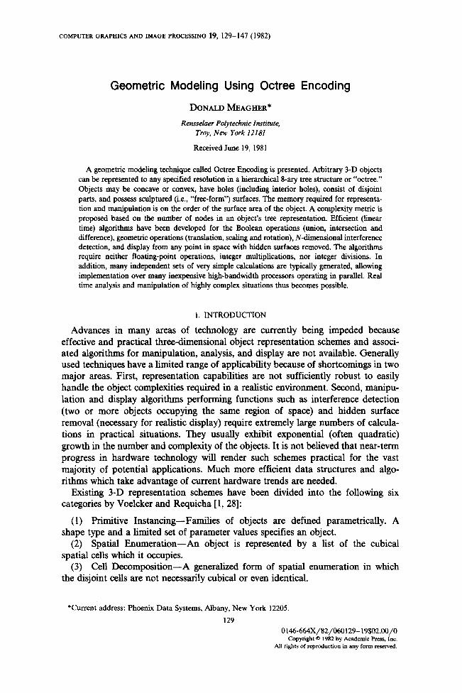
The “property” as used here will be a simple description of the state of the obel having the values EMPTY, PARTIAL and FULL, indicating that the obel is entirely free of the object, partially filled with the object or is completely occupied by the object, respectively. The property could be a much more complex description containing such items as material type, color, function, density, thermal conductiv- ity, etc.
The position of a child node is indicated by a value from the child number set {0,1,2,..., rn- l}, where m=2 N. Every node is uniquely identified by a node address, which is a string over the child number set. The root is represented by the empty string. The node address of a child is the child number prefixed by the
OCTREE ENCODING 135
EMPTY (“En)- CUBE IS EMPTY FULL (“F”)- CUBE IS COMPLETELY ENCLOSED
BY THE OBJECT PARTlAL(“P”)- CUBE PARTLY INTERSECTS
OBJECT
OBJECT REPRESENTATION
b
FIG. I. Simple object represented in Octree Encoding format. (a) Numbering sequence and label definitions. (b) Three-level tree representation of an object.
address string of its parent. This identifies a particular node and it gives the series of traversal commands to locate the node relative to the root. It also identifies the section of space represented or covered by the node.
A node address in a 1-D tree is a binary string. The number of bits used is equal to the level of the node. The value is the number of the section of the 1-D universe covered by the node, numbered from 0 at the origin to 2k - 1 where k is the level. The covered section of a higher order universe can be likewise determined by independently considering the individual bit for each dimension in the child number values of the node address string.
Figure 1 shows an example. In Fig. la, the numbering sequence and node labeling are defined. Figure lb shows a three level tree representing a three cube object at level 2. The child nodes are numbered from 0 to 7 from left to right.
5. COMPLEXITY METRIC
An important item that is generally lacking in the field of 3-D geometric modeling is a measure of object complexity. It is difficult to study a situation analytically when quantitative measures are not available. Intuitively, the measure of the complexity of an object should in some sense be related to the amount of informa- tion required to represent the object. When a particular encoding scheme is selected, however, certain problems become immediately apparent. In a CSG scheme, for example, a cylinder can be represented very compactly with a few values, indicating a very low complexity. If the surface of the cylinder is then slightly deformed, the
136 DONALD MEAGHER
complexity may increase explosively because additional primitives must be fitted to the new object. In one sense, information has been added to the object but in a practical situation, the object may have changed very little. From a functional or applications point of view the two objects may be equivalent.
This problem exists whenever the object corresponds to one or a small set of the primitive shapes. An abnormally low complexity results. Also, the measure will change depending on the primitives allowed in a particular system and on the ability of the system and user to determine an optimum fitting of primitives.
The object complexity metric proposed here is the number of nodes in its octree. In practice, a family of complexity values is generated, one for each level. Each lower level contains a more faithful representation of the object and a corresponding higher complexity.
The ideal cylinder represented by an octree would show a relatively large complex- ity value when compared to CGS but the deformed object would probably change very little. At the higher levels, the two objects would be identical or almost identical.
This complexity measure is reasonably well behaved over a large domain of objects, especially those with curved surfaces. It tends, however, to generate abnorm- ally low complexity values for box-like objects with sides oriented parallel to the axes of the coordinate system because of the correspondence to the primitive shape (the cube).
The actual complexity value will depend on location and orientation. Objects could be normalized by translation so that they touch the three sides of the universe that intersect the origin. If there is no preferred object orientation, an average could be calculated for the object at uniformly distributed rotation angles. Alternately, the minimum (or maximum) number of nodes could be used.
An advantage is the ease of calculation. A complexity value can be generated automatically for any object with existing algorithms without manual intervention.
6. OBJECT MANIPULATION
The primary object manipulations are the Boolean operations (union, intersection, and difference) and the geometric operations of translation, scaling and rotation. The Boolean operations are the “regularized” operators [24]. An intersection must contain volume, for example. Thus the intersection of two 3-D objects that touch along a surface is the null set. Conveniently, this is the normal result of tree manipulation operations.
Boolean operations are straightforward tree traversal algorithms. They have been described elsewhere [IO] for 2-D quadtrees and are easily extended into 3-D.
Translation
The goal of the translation algorithm is to convert a tree representing an N-dimensional object and a movement vector into a new tree representing the translated object. The movement vector specifies a translation value to some precision, i.e. at some level for each dimension. An informal description of the algorithm follows.
The process begins by generating an “old” universe composed of the universe containing the original object and a number of empty universes. It is put together so that the “new” universe containing the translated object is covered (completely
enclosed) by the old universe. The translation vector specifies the alignment of the new universe relative to the old.
Beginning with the root of the new universe, the basic strategy is to traverse the implied tree for the new object and generate node values by simultaneously traversing the tree representing the old universe. If a terminal value for a node in the new tree is generated, no descendants of that node need be considered. If an ambiguity exists and, therefore, the status cannot be resolved, a nonterminal node is generated and the children of that node are generated in like manner.
Information is passed from the parent to the children through a queue for breadth-first traversal or a stack for depth-first traversal.
There are a number of schemes that can be used to traverse the tree structures and generate node values. The algorithms developed to date make use of overlays. The value of a node or obel in the new universe is completely determined by the obels in its overlay record or their descendants. The overlay obels present a picture of the section of the old universe that covers the new obel. They can be at any level relative
138 DONALD MEAGHER
to the target (new) obel. The lower they are below the target, the more numerous but the more accurate the result. The output tree will be more nearly the final reduced tree. This comes at an increase in memory use and computation. The translation algorithm normally uses an overlay with 2N obels at the same level as the corre- sponding obel in the new universe.
If all overlay obels are terminal with the same status value, the overlaid obel also has that value. If all overlay obels which are known to intersect the target obel are FULL or EMPTY, the new obel is FULL or EMPTY, respectively. Otherwise, the decision is passed to the next lower level.
Figure 2a illustrates the overlay in one dimension. Distance is positive to the right. Three obels are shown. The target obel has an edge distance of e. Its lower end is the local origin. The overlay is made up of two adjacent obels of the same size from the old universe connected at the overlay center. The offset value is the distance from
the local origin to the overlay center. The value of offset is limited as follows:
0 I offset < e.
Figure 2b shows the configuration of a 2-dimensional overlay. The eight overlay cubes and the target cube for 3-D translation are illustrated in Fig. 3. The concept is easily extended to N-dimensional overlays containing 2N obels.
Scaling
Scaling an object by a power of two in all dimensions is accomplished by adding or deleting levels at the root. An object is halved in each dimension by adding one level at the top. The new root points to one branch node, the old root, and 2N - 1 empty terminal nodes. The scaled down universe can be located in any of the first-level obels in the new universe.
In a like manner, selecting one of the first level nodes to be a new root doubles the size of anything within it. To double the size of an arbitrary section of space, it is translated into a first level obel which is then expanded to fill the new universe.
Objects can be expanded or reduced by any power of two by, in effect, repeated expansion or reduction by a factor of 2. These scaling operations can be accom- plished by manipulating a very small number of nodes at the top of the tree. The vast bulk of the data values are left unchanged.
Scaling by a factor of other than a power of 2 is accomplished using an overlay scheme similar to that developed for translation. The target obel, however, may be smaller than the overlay in one or more dimensions. In addition, one set of offset values cannot be used throughout the algorithm. The offset vector must be computed independently for each child of the target obel.
Rotation
Rotation by 90’ about an axis can be performed by a simple reordering of the nodes in the tree. For an octree, if the center of rotation is the center of the universe, rotation by 90”, 180°, or 270’ or reflection across a plane through the center parallel to a face of the universe or oriented at 45” is accomplished by reordering or, within an algorithm, a change in the traversal sequence.
For rotation about an arbitrary point, the object is translated to the center of the universe, rotated, and translated back.
TARGET OBEL
\ LOCAL ORIGIN OF OVERLAY
FIG. 4. Rotation overlay
140 DONALD MEAGHER
LINE L, EDGE OF TARGET OBEL
I-
Ax+Bv+C=O A’+dl
FIG. 5. Determination of intersection. For each corner point Pr and line LJ there is a distance D, such that if C’ > D,, the line is above the point.
Rotation by an arbitrary angle is somewhat more difficult. The basic overlay scheme is extended so that rotation can be performed without the use of floating-point operations, integer multiplications or integer divisions.
In 2-D, the overlay arrangement for a 0” to 90” rotation is shown in Fig. 4. Nine overlay obels are required. The local origin of the new obel is always in overlay obel B. The steps in computing a property value for the new obel are as follows:
(1) Determine overlay obels which intersect target obel. (2) If all intersecting obels are EMPTY, mark new obel as EMPTY. (3) If all intersecting obels are FULL, mark new obel as FULL. (4) If not all intersecting obels are either FULL or EMPTY, then mark new obel
as PARTIAL, subdivide target obel and repeat.
The most difficult part of the operation is step 1, determining the intersecting obels. One method is shown in Figure 5. Each edge of the new obel is represented by a normalized equation of the form Ax + By + C = 0. The perpendicular distance to the origin of the coordinate system (the overlay origin is used) is C. For each vertex point in the overlay, there is a distance D from the origin such that if C > D, the line is above the vertex point. This information, together with the location of the vertex points of the target obel completely determines the intersecting overlay obels.
Because the edges of the target obel are orthogonal, the C values after subdivision are the average of two parent values. Only an addition followed by a divide by 2 (shift one bit position) is required.
For an arbitrary object rotation, three operations could be performed using a slightly modified 2-D algorithm, one for each axis. This is generally undesirable, however, because at the lowest levels aliasing products are generated on the object surface when nodes are forced to be terminal. The object is essentially being redigitized from a previously digitized object. This tends to corrupt the surface and is compounded by repeated operations. This is minimized by computing nodes to lower levels, by performing operations in a single pass and by regenerating instances of an object from the original octree model each time it is moved or changed (rather than incremental movement of a single object).
Because of this, 3-D rotation in one pass is preferred. This is accomplished by extending the 2-D scheme into 3-D by the use of a 4 by 4 by 4 overlay.
OCTREE ENCODING 141
X’
FIG. 6. Target obel for concatenated geometric transformation.
Concatenated Geometric Operations
Using homogeneous coordinates [25] any number of sequential linear operations (x’ = ax + by + c, y’ = dx + ey + f) can be concatenated and reduced to a single matrix of coefficients (3 by 3 for 2-D or 4 by 4 for 3-D). This, of course, includes the geometric operations of translation, scaling and rotation. The composite transforma- tion can then be performed in a single matrix multiplication. This can be expressed as follows for 2-D:
Al A2 0 [x’, y’, l] = [x, y, 11 1 Bl B2 0 .
Cl c2 1 1
Reversing for the moment the direction of data flow in an overlay operation (the target obel will now “generate” the overlay) it can be shown that the above concatenated transformation will be performed if a parallelogram-shaped target obel is used as shown in Fig. 6. The matrix coefficients determine the location, orienta- tion and shape as noted in the diagram.
Returning to the original data flow from overlay to target obel, the new obel is generated from the overlay when it is deformed according to the inverse of the coefficient matrix.
7. PERSPECTIVE TRANSFORMATION
In order to avoid the division required in generating a perspective display, the objects can be deformed so as to appear as if in a perspective view when an orthographic projection is used.
T I SCREEN
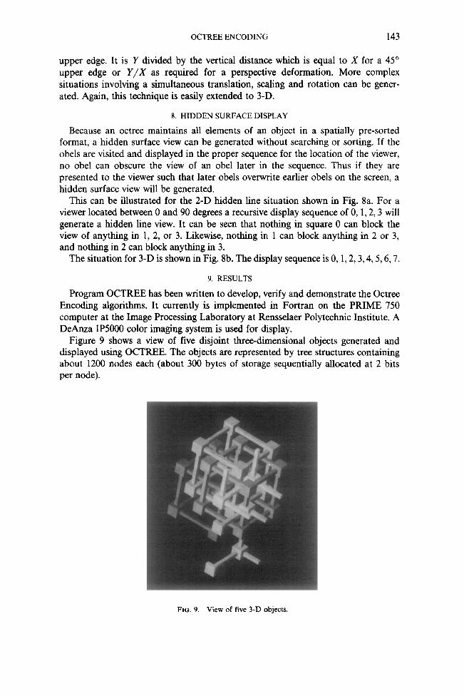
FIG. 7. Target obel for perspective transformation.
142 DONALD MEAGHER
For the situation in Fig. 7a, an object with a height of Y at a location X units from the observer should be “stretched” to a height of Y’ units according to the following:
Y/Xs = Y/Xor Y = YXs/X.
For simplicity, let XS = 1. Thus, Y’ reduces to:
Y = Y/X.
The target obel shape shown in Figure 7b will perform this transformation. The value of Y’ will be the fraction of the distance from the base of the target obel to the
t DIMENSION 2
T DIMENSION 2
ENSION 3
DIMENSION I b
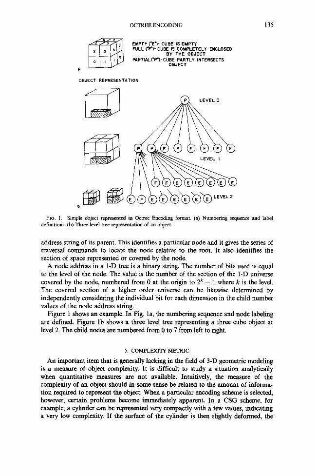
FIG. 8.(a) 2-D hidden line sequence. For a viewer located between 0” and 90”, a display sequence of 0, 1,2,3, will generate a 2-D hidden line view. (b) 3-D hidden surface sequence. For a viewer located between 0” and 90” in each view angle, a display sequence of 0, I, 2,3,4,5,6,7 will generate a hidden surface view.
OCTREE ENCODING 143
upper edge. It is Y divided by the vertical distance which is equal to X for a 45” upper edge or Y/X as required for a perspective deformation. More complex situations involving a simultaneous translation, scaling and rotation can be gener- ated. Again, this technique is easily extended to 3-D.
8. HIDDEN SURFACE DISPLAY
Because an octree maintains all elements of an object in a spatially pre-sorted format, a hidden surface view can be generated without searching or sorting. If the obels are visited and displayed in the proper sequence for the location of the viewer, no obel can obscure the view of an obel later in the sequence. Thus if they are presented to the viewer such that later obels overwrite earlier obels on the screen, a hidden surface view will be generated.
This can be illustrated for the 2-D hidden line situation shown in Fig. 8a. For a viewer located between 0 and 90 degrees a recursive display sequence of 0, 1,2,3 will generate a hidden line view. It can be seen that nothing in square 0 can block the view of anything in 1, 2, or 3. Likewise, nothing in 1 can block anything in 2 or 3, and nothing in 2 can block anything in 3.
The situation for 3-D is shown in Fig. 8b. The display sequence is 0, 1,2,3,4,5,6,7.
9. RESULTS
Program OCTREE has been written to develop, verify and demonstrate the Octree Encoding algorithms. It currently is implemented in Fortran on the PRIME 750 computer at the Image Processing Laboratory at Rensselaer Polytechnic Institute. A DeAnza IP5000 color imaging system is used for display.
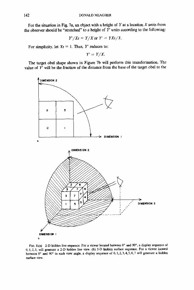
Figure 9 shows a view of five disjoint three-dimensional objects generated and displayed using OCTREE. The objects are represented by tree structures containing about 1200 nodes each (about 300 bytes of storage sequentially allocated at 2 bits per node).
FIG. 9. View of five 3-D objects.
144
FIG. IO. View of milling operation.
FIG. I I. View after machining operation.
FIG. 12. Top, front, side, and orthographic views of machining operation.
OCTREE ENCODING 145
FIGURE 13.
FIGURE 14.
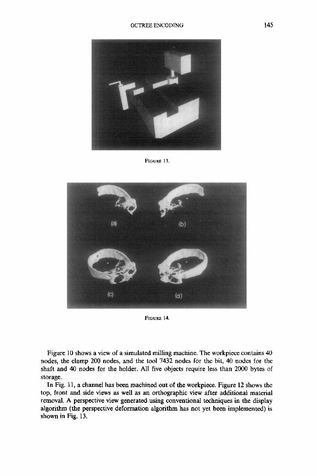
Figure 10 shows a view of a simulated milling machine. The workpiece contains 40 nodes, the clamp 200 nodes, and the tool 7432 nodes for the bit, 40 nodes for the shaft and 40 nodes for the holder. All five objects require less than 2000 bytes of storage.
In Fig. 11, a charmel has been machined out of the workpiece. Figure 12 shows the top, front and side views as well as an orthographic view after additional material removal. A perspective view generated using conventional techniques in the display algorithm (the perspective deformation algorithm has not yet been implemented) is shown in Fig. 13.
146 DONALD MEAGHER
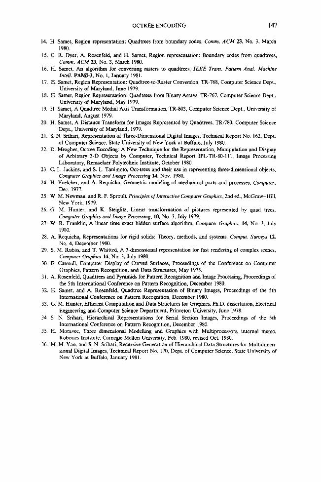
Figure 14 shows four views of a section of a human skull generated from 42 CT (Computed Tomography) images. ’ Figures 14a and b are cutaway views of Figs. 14 c and d, respectively. The octree representing the object in Figs. 14c and d contained 172,448 nodes. Figure 14a contained 88,936 nodes.
IO. SUMMARY
A geometric modeling scheme for applications such as computer-aided design and computer-aided manufacturing has been presented which provides several important advantages over competing techniques. Using a common hierarchical data structure, any object of arbitrary complexity can be represented to a specified precision (within memory limits). Efficient algorithms have been developed for the Boolean and geometric transformations, interference detection and hidden surface display, none of which require floating point operations, integer multiplications, or integer divi- sions (other than shifts). In the future, they could be implemented in many simple, high-speed processors operating in parallel, for real-time manipulation and display of many complex objects.
ACKNOWLEDGMENTS
The author would like to thank Professor Herbert Freeman of the Image Process- ing Laboratory at Rensselaer Polytechnic Institute for direction, support and encouragement in this effort.
This research was partially funded through the National Science Foundation’s Automation, Bioengineering and Sensing Program under Grant ENG-79-04821.
REFERENCES 1. A. Requicha, and H. Voelcker, Geometric Modeling of Mechanical Parts and Machining Processes,
COMPCONTROL 1979, Sopron, Hungary, Nov. 1979. 2. A. Requicha, and H. Voelcker, A Tutorial Introduction to Geometric Modelling, SIGGRAPH 1980
Tutorial, July 1980. 3. A. Baer, C. Eastman, and M. Henrion, Geometric modeling: A survey, Cornpurer-Aided Design 11,
No. 5, Sept. 1979. 4. J. Clark, Hierarchical geometric models for visible surface algorithms, Comm. ACM 19, No. 10, Oct.
1976. 5. J. L. Bentley, Multidimensional divide-and-conquer, Comm. ACM 23, No. 4, April 1980. 6. J. L. Bentley, Multidimensional binary search trees in database applications, IEEE Tranr. Software
Engrg. SES, No. 4, July 1979. 7. W. R. Franklin, Locating a Point in Overlapping Regions of Hyperspace, Technical Report CLR-64,
Rensselaer Polytechnic Institute, Dec. 1978. 8. G. S. Sidhu, and R. T. Boute, Property encoding: Applications in binary picture encoding and
boundary following, IEEE Trans. Comput. C-21, No. 11, Nov. 1972. 9. S. L. Tanimoto, A Pyramid Model for Binary Picture Complexity, Proc. IEEE Computer Society
Conference on Pattern Recognition and Image Processing, Rensselaer Polytechnic Institute, June 1977.
IO. G. M. Hunter and K. Steiglitz, Operations on images using quad trees, IEEE Trans. Putfern Anal. Machine Intell. PAM&l, No. 2, April 1979.
11. A. Rosenfeld, Tree Structures for Region Representation, Computer Vision Laboratory, University of Maryland, 1979.
12. H. Samet, Computing Perimeters of Images Represented by Quadtrees, TR-755, Computer Science Center, University of Maryland, College Park, April 1979.
13. H. Samet, Comxcted component using quadtrees, J. Assoc. Compur. Mach. 28, 3, July 1981.
‘CT scans courtesy Dr. Gabor Herman, Medical Image Processing Group, State University of New York at Buffalo. (Present address: University of Pennsylvania.)
OCTREE ENCODING 147
14. H. Samet, Region representation: Quadtrees from boundary codes, Comm. ACM 23, No. 3, March 1980.
IS. C. R. Dyer, A. Rosenfeld, and H. !&met, Region representation: Boundary codes from quadtrees, Comm. ACM 23, No. 3, March 1980.
16. H. Same& An algorithm for converting rasters to quadtrees, IEEE Trans. Pattern Anal. Machine Intell. PAM&J, No. 1, January 1981.
17. H. &met, Region Representation: Quadtree-to-Raster Conversion, TR-768, Computer Science Dept., University of Maryland, June 1979.
18. H. Same& Region Representation: Quadtrees from Binary Arrays, TR-767, Computer Science Dept., University of Maryland, May 1979.
19. H. Samet, A Quadtree Medial Axis Transformation, TR-803, Computer Science Dept., University of Maryland, August 1979.
20. H. Samet, A Distance Transform for Images Represented by Quadtrees, TR-780, Computer Science Dept., University of Maryland, 1979.
21. S. N. Sribari, Representation of Three-Dimensional Digital Images, Technical Report No. 162, Dept. of Computer Science, State University of New York at Buffalo, July 1980.
22. D. Meagher, Octree Encoding: A New Technique for the Representation, Manipulation and Display of Arbitrary 3-D Objects by Computer, Technical Report IPL-TR-80-11 I, Image Processing Laboratory, Rensselaer Polytechnic Institute, October 1980.
23. C. L. Jackins, and S. L. Tanimoto, Ott-trees and their use in representing three-dimensional objects, Computer Graphics and Image Processing 14, Nov. 1980.
24. H. Voelcker, and A. Requicha, Geometric modeling of mechanical parts and processes, Computer, Dec. 1977.
25. W. M. Newman, and R. F. Sproull, Principles of Interactive Computer Graphics, 2nd ed., McGraw-Hill, New York, 1979.
26. G. M. Hunter, and K. Steiglitz, Linear transformation of pictures represented by quad trees, Computer Graphics and Image Processing, 10, No. 3, July 1979.
27. W. R. Franklin, A linear time exact hidden surface algorithm, Computer Graphics, 14, No. 3, July 1980.
28. A. Requicha, Representations for rigid solids: Theory, methods, and systems, Comput. Surveys 12, No. 4, December 1980.
29. S. M. Rubin, and T. Whitted, A 3dimensional representation for fast rendering of complex scenes, Computer Graphics 14, No. 3, July 1980.
30. E. Catmull, Computer Display of Curved Surfaces, Proceedings of the Conference on Computer Graphics, Pattern Recognition, and Data Structures, May 1975.
3 I. A. Rosenfeld, Quadtrees and Pyramids for Pattern Recognition and Image Processing, Proceedings of the 5th International Conference on Pattern Recognition, December 1980.
32. H. Samet, and A. Rosenfeld, Quadtree Representation of Binary Images, Proceedings of the 5th International Conference on Pattern Recognition, December 1980.
33. G. M. Hunter, Efficient Computation and Data Structures for Graphics, Ph.D. dissertation, Electrical Engineering and Computer Science Department, Princeton University, June 1978.
34. S. N. Srihari, Hierarchical Representations for Serial Section Images, Proceedings of the 5th International Conference on Pattern Recognition, December 1980.
35. H. Moravec, Three dimensional Modelling and Graphics with Multiprocessors, internal memo, Robotics Institute, Carnegie-Mellon University, Feb. 1980, revised Oct. 1980.
36. M. M. Yau, and S. N. Srihari, Recursive Generation of Hierarchical Data Structures for Multidimen- sional Digital Images, Technical Report No. 170, Dept. of Computer Science, State University of New York at Buffalo, January 1981.