Artificial Intelligence 98 (1998) 237-279 Artificial Intelligence Geometric reasoning about assembly tools Randall H. Wilson * Intelligent Systems and Robotics Center, Sandia National Laboratories, Albuquerque, NM 87185-1008, USA Received January 1997 Abstract Planning for assembly requires reasoning about various tools used by humans, robots, or other automation to manipulate, attach, and test parts and subassemblies. This paper presents a general framework to represent and reason about geometric accessibility issues for a wide variety of such assembly tools. Central to the framework is a use volwne encoding a minimum space that must be free in an assembly state to apply a given tool, and placement constraints on where that volume must be placed relative to the parts on which the tool acts. Determining whether a tool can be applied in a given assembly state is then reduced to an instance of the FINDPLACE problem (Lozano-Perez, 1983). In addition, we present more efficient methods to integrate the framework into assembly planning. For tools that are applied either before or after their target parts are mated, one method preprocesses a single tool application for all possible states of assembly of a product in polynomial time, reducing all later state-tool queries to evaluations of a simple expression. For tools applied after their target parts are mated, a complementary method guarantees polynomial-time assembly planning. We present a wide variety of tools that can be described adequately using the approach, and survey tool catalogs to determine coverage of standard tools. Finally, we describe an implementa- tion of the approach in an assembly planning system and experiments with a library of over one hundred manual and robotic tools and several complex assemblies. @ 1998 Elsevier Science B.V. Keywords: Assembly; Geometric reasoning; Planning; Manufacturing; Robotics * Present address: Eastman Kodak Company, 2901 Juan T&o NE, Suite 210, Albuquerque, NM 87112-1881, USA. Email: [email protected]. 0004-3702/98/$19.00 @ 1998 Elsevier Science B.V. All rights reserved. PIISOOO4-3702(97)00062-3
Transcript
Artificial Intelligence 98 (1998) 237-279
Artificial Intelligence
Geometric reasoning about assembly tools
Randall H. Wilson * Intelligent Systems and Robotics Center, Sandia National Laboratories,
Albuquerque, NM 87185-1008, USA
Received January 1997
Abstract
Planning for assembly requires reasoning about various tools used by humans, robots, or other automation to manipulate, attach, and test parts and subassemblies. This paper presents a general framework to represent and reason about geometric accessibility issues for a wide variety of such assembly tools.
Central to the framework is a use volwne encoding a minimum space that must be free in an assembly state to apply a given tool, and placement constraints on where that volume must be placed relative to the parts on which the tool acts. Determining whether a tool can be applied in a given assembly state is then reduced to an instance of the FINDPLACE problem (Lozano-Perez, 1983). In addition, we present more efficient methods to integrate the framework into assembly planning. For tools that are applied either before or after their target parts are mated, one method preprocesses a single tool application for all possible states of assembly of a product in polynomial time, reducing all later state-tool queries to evaluations of a simple expression. For tools applied after their target parts are mated, a complementary method guarantees polynomial-time assembly planning.
We present a wide variety of tools that can be described adequately using the approach, and survey tool catalogs to determine coverage of standard tools. Finally, we describe an implementa- tion of the approach in an assembly planning system and experiments with a library of over one hundred manual and robotic tools and several complex assemblies. @ 1998 Elsevier Science B.V.
“Man is a tool-using animal . . . . Without tools he is nothing, with tools he is all.” - Thomas Carlyle, Sartor Resartus, book I, 1833.
Planning for assembly, servicing, and disassembly of a product is a critical step in the design realization process for that product. In addition, assembly planning can supply important feedback to help designers improve the design from a manufacturing standpoint. Computer-aided assembly planning promises to reduce the labor required to produce assembly plans while increasing their quality and completeness. Since the need to manipulate, attach, and test parts and subassemblies leads to important con-
straints on assembly plans, methods must be developed to reason about these con- straints. This paper proposes an approach to cover a wide variety of such constraints and describes an implementation of the approach in a prototype assembly planning
system. We focus on representing and reasoning about the geometric requirements of applying
various tools in assembly. Assembly tools are implements used to manipulate, attach, and test parts and subassemblies during the processes of assembly and disassembly. Tools in this sense include manual tools such as screwdrivers and hammers, robotic
tooling such as welders and bolt drivers, and a number of other items such as laser welders, riveters, and part-manipulation devices used in more traditional automation.
Inspection tools include robotic cameras, coordinate measuring machines, and human eyesight. Although these may seem like a diverse group of implements, they all share
certain aspects that allow them to be reasoned about in a common way. We call the constraints on assembly plans deriving from the need to use various tools in assembly
or disassembly tool constraints. We present a framework to represent and reason about the geometric accessibility of
tools in assembly resulting in necessary constraints on assembly plans. We begin by classifying tools by whether they are used before, during, or after mating of the parts upon which the tools act. A use volume encodes a minimum space that must be free
in a subassembly to apply the tool, and placement constraints determine where that volume must be placed relative to a canonical reference frame. A particular application of the tool then defines which parts of a product the tool acts upon and places the tool’s canonical reference frame at the position of required tool use.
Given this representation, a tool can be applied in a given subassembly only if a placement of its use volume exists that satisfies the placement constraints and does not collide with any parts in the subassembly. This is an instance of the FINDPLACE problem [ 281. However, a typical assembly planner will make many queries about tool accessibility for a single tool application. For tools that are applied either before or after their target parts are mated (which includes the great majority of tools), we describe polynomial-time methods to preprocess a single tool application for all possible states of assembly of a product, reducing all later queries to evaluations of a simple expression. Moreover, for tools that are applied after their target parts are mated, we present an extension to previous assembly planning techniques that guarantees polynomial-time assembly planning with tools.
R. H. Wilson /Art$cial Intelligence 98 (1998) 237-279 239
While limited to geometric accessibility issues, the approach provides coverage for a
wide variety of assembly tools. We present a number of examples and survey catalogs of standard mechanical tools to determine how well the approach covers typical assembly tools. We also describe an implementation of the approach in an assembly planning
system and show experiments with a library of over one hundred manual and robotic tools and several complex assemblies.
The next section describes the problem of planning with tools in greater detail, mo-
tivates our approach, and describes assumptions and limitations. Section 3 describes previous work addressing this and related problems. Sections 4 and 5 present our frame- work for tool constraints. Section 6 gives examples of tools represented using the approach and the results of our tool catalog surveys. Section 7 then shows how the
constraints are evaluated for single operations as well as efficiently integrated into an assembly Iplanning system. Section 8 describes our implementation and experiments. Finally, Section 9 discusses several aspects of the approach, describes future work and
open issues, and concludes.
2. Problem and motivation
“But lo! men have become the tools of their tools.” - Henry David Thoreau, “Economy”, 1854.
We are primarily interested in representing and reasoning about assembly tools be- cause of their impact on assembly plans and planning. Planning the assembly process for a complex product is demanding and time-consuming, and costly mistakes are of- ten made because the constraints cannot be reasoned about and resolved accurately enough or quickly enough. Determining tool access constraints in complex geometric situations :is particularly difficult for humans early in the design process unless costly
(in time and money) prototypes are fabricated. Automated or partially automated meth- ods to reason about tool constraints and assembly plans would help alleviate these problems.
Althouglh assembly planning is our main motivation and application area for reasoning about tools, we hope that the framework developed here will be applicable to other areas where assembly tools are used, such as assembly plan simulation, validation, and visualization. We believe that at least some of these areas will be less demanding than assembly planning on the tool representation and reasoning methods.
2.1. Assembly planning
An assembly is a product consisting of two or more independently-fabricated pieces, called pan’s; a subassembly is any nonempty subset of the parts of an assembly. An
assembly plan for a product is a sequence of motions and manipulations of the parts that transforms the individual parts into the finished product. Given a complete description of an assembly, assembly planning is the problem of determining a feasible assembly plan for it. Closely related to assembly plans are disassembly plans and service plans,
240 R.H. Wilson /Artijicial Intelligence 98 (1998) 237-279
the latter being plans for partial disassembly and re-assembly. The planning techniques can differ somewhat for these processes, but in this paper we will mainly discuss assembly planning. Most of the methods transfer easily to disassembly and service planning.
In theory, a complete assembly plan includes every detail of the assembly process down to the factory floor, including the motions of all parts, humans, and robots that put it together and full descriptions of the fixtures, jigs, tools, etc. that are used. In practice,
assembly plans are almost never written down in that much detail; at the very least, line workers decide their own body motions to assemble the product. The assembly process itself is its only true description. Instead, representations of assembly plans are abstractions: they specify the assembly plan down to a certain level of detail, and leave the corresponding complete plan to be determined.
Automated assembly planners therefore must plan for assembly at some level of abstraction. Because they don’t reason about the constraints below their abstraction level,
they often produce plans that, when those constraints are considered, are not feasible. This paper is intended as one step further down the abstraction hierarchy, to generate assembly plans in more detail that are therefore more likely to be feasible. Alternatively, the resulting planners will require less human input in an interactive assembly planning
system. We will limit consideration to monotone two-handed assembly plans [ 37,391. In an
abstract view, such plans consist of a sequence of operations, where each operation places two rigid subassemblies Si and S2 in their final relative positions via a mating trajectory t. Most industrial products are made with monotone two-handed assembly
plans. For an assembly with n parts, any monotone two-handed assembly plan has n - 1 operations. At a lower level of abstraction, the operations break down into many sub-operations, some of which involve the use of tools.
Disassembly planning is a standard approach to automatically generating monotone two-handed assembly plans. The planner begins with the full assembly, and attempts to find a subassembly that could be placed as the last operation. This is called the partitioning problem. If the planner succeeds, then it partitions each of the two resulting subassemblies, and continues until individual parts remain. Although we take this view throughout the paper, the tool framework is compatible with other assembly planning approaches with some modifications.
2.2. Tool constraints
A tool is an implement used to manipulate, attach, test, modify, or otherwise affect a part or set of parts in an assembly. We call the constraints on assembly plans de- riving from the need to use various tools in assembly or disassembly tool constraints. Tool constraints are important to consider when determining an assembly plan for and designing a product. In some cases, the optimal assembly plan is determined by tool constraints. In others, the main goal is to ensure assemblability with a given tool set that is already present in a facility or servicer’s tool kit.
If standard tools cannot be used to implement a given assembly plan, then a different plan must be chosen, the product must be redesigned, or special-purpose tools must
Fig. 1. Special-purpose tools used to avoid geometric accessibility problems while servicing engines from a single manuFacturer [ 21. Photo used by permission of Snap-on Inc.
be fabricated. Fig. 1 shows a set of tools whose only purpose is to solve geometric accessibility problems while servicing a particular make of engine. Such special-purpose tools can be quite expensive, especially when they must be distributed to and stored at every in-field service center for the product. Taking tool constraints into account early in product design will help minimize the need for such tools.
In man,y cases process engineers find it difficult to determine tool accessibility for assembly operations. This is especially true in cramped spaces containing geometrically complex parts that may interfere with the operation, such as inside the engine com- partment of a modern automobile. The problem is exacerbated by products designed by a large group of designers. Even when humans can accurately determine the feasible uses of tools, automated assembly planners that include tool constraints would produce assembly plans with less human effort, allowing the results to be used earlier and more often in product realization and design-for-assembly.
2.3. Tool-level assembly planning
Let a given use of a tool to affect a particular set of parts be called an application of that tool. For instance, an application might be to use wrench2 to tighten bolt6 into block3. We assume that an unordered list of all tool applications required during assembly is given as input to the assembly planner. Note that in this model the tool ap- plications required cannot depend on the order of assembly: we do not allow constraints such as “attaching part A to part B requires tool T only if part C is missing.” We also assume that a tool is used within a single operation, i.e. it is used just before, during, or just after a single mating of two subassemblies. This rules out, for instance, including fixtures in our framework, because they affect multiple operations.
242 R. H. Wilson/Art@ial Intelligence 98 (1998) 237-279
A tool-level assembly plan for a product is a sequence of part motions and tool applications that will construct the product from its constituent parts. The plan must include all required tool applications. Then the problem of tool-level assembly planning is the following: given an assembly and a list of tool applications, find a feasible tool- level assembly plan for the product, or determine that no such plan exists. Because a tool-level assembly plan is an abstraction, such a feasible plan may of course fail once
lower-level details are considered. The two main questions a tool-level assembly planner must be able to answer about
any tool are “When does this tool need to be used?” and “When can this tool be used?’ In our approach, the first issue is addressed by a tool’s relative time (whether it is applied before, during, or after the mating of parts) and the tool application’s
target part set, which determines the assembly operations that the tool must be used to accomplish. We give necessary constraints for the second issue by representing the tool’s geometric requirements as a volume that must be free in the assembly, together with constraints on the placement of that volume. This framework provides a basic representation of tool accessibility constraints that is applicable to a wide variety of common assembly tools and can be efficiently used by an assembly plan-
ner.
2.4. Limitations of the approach
This paper focuses on representing and reasoning about geometric accessibility issues
regarding the use of tools. Thus we are mainly concerned with the question “Is there space for this tool to be used?” This is the main question product designers have told us they struggle with, and we have attempted to design a framework for reasoning about
geometric tool constraints that captures as much of the issue as possible in a practical way. Although the framework does not cover many other questions one might wish to ask about tools, and in fact does not completely solve the geometric accessibility issue, we believe it achieves broad coverage and lays the foundation for further extensions to address those other questions.
Among the issues we do not address are: - Determining applications. Many tool applications are specified in the assembly
design (such as weld points and press fits), or can be inferred easily from the CAD data (for instance, that a screwdriver is needed to tighten each screw). Beyond that, automatically determining required tool applications becomes a difficult feature- recognition task.
- The tool wielder. Reasoning about the spatial requirements of the agent wielding the tool (a robot or human arm, or hard automation) is beyond the scope of this work. Human hands in particular are extremely flexible, and determining automatically whether they (or mechanical tool wielders) will be able to reach and manipulate a tool is very complex (see e.g. [25] ). As a result, the tool constraints considered in this paper are necessary but not sufficient constraints on tool-level assembly plans.
- Mechanics. Which tools can accomplish a task often depends on non-geometric is- sues such as the force that must be applied, accuracy required, expected deformation forces, possible damage to the parts, and so on.
- Optimal tool-level plans. The desirability of using a certain tool can depend on many factors, including the forces required, the speed and accuracy with which it can be used, and the tools needed for previous and following opera- tions. A planner based on our framework could easily output a list of possible tools to accomplish each task, to support such optimization in a later planning
phase. - Tool interaction. There might be two tools required in an operation at the same
time that interfere with each other. We assume that the the feasibility of each tool can b’e determined independently of other tools used (either simultaneously or in sequence) in the same operation.
- Nonsfandard tools. In some cases a special-purpose tool can be created when stan-
dard tools do not suffice, or a standard tool can be used in a nonstandard way (e.g. using a screwdriver to pound a nail).
- Design changes, The inability to use a standard tool often suggests that the design
be changed to allow such access, but we do not go beyond this observation. Some of .the above issues are addressed in previous work on reasoning about tools, given below. We believe many of these issues can be addressed in the context of our framework, but they are not the main focus of this work.
3. Previotus work
“You ought to be able to show that you can do it a good deal better than anyone else with the regular tools before you have a license to bring in your own
improvements.” - Ernest Hemingway (on punctuation), 1925. Selected Letters, 1981.
The previous work related to representing and reasoning about tool constraints can be roughly divided into five parts: assembly sequencing work on “attachments,” plan- ning for machine tools, general-purpose reasoning about tools, special-purpose planners for specific tools, and work on estimating the difficulty of fastening operations when obstructions are present. In addition, our approach to representing and reasoning about
tool acces:sibility is based on now standard configuration-space techniques introduced by Lozano-Perez [ 281.
3. I. Assembly sequencing and attachments
The past decade has seen a great deal of research on assembly planning and related topics (see, e.g., [ 1,19,29] ). Most focuses on graph-theoretic techniques and constraint languages and on collision avoidance. However, much of this research points to a need for more rigorous and powerful methods to reason about tool constraints.
For instance, Homem de Mello and Sanderson [ 18,201 use a relational model of assemblies as the basis of their assembly sequencing approach. The relational model includes attachments between parts in the assembly, which correspond to fastening op- erations. Each attachment contains a list of the other parts whose presence prevents
the attachment from being accomplished. ’ However, [ 18,201 do not address how to determine which parts prevent which attachments. This paper provides a partial an- swer.
Henrioud and Bourjault [ 161 use a similar product model, including attachment information. However, their model does not represent parts that prevent attachments; instead, they defer to the expert judgement of an engineer to determine the feasibility of an attachment in a given subassembly. The answer is stored in a database of constraints on the assembly. This can cause many hundreds of questions to be asked of the engineer, some of which can be very difficult to answer accurately in complex assemblies. As a result the system cannot reasonably be applied to assemblies with more than about 20 parts.
Miller and Hoffman [ 301 describe a system that requires access space above screws, bolts, and nuts before they can be removed. However, the tests used to determine access are very simple, consisting of ray casting and box tests, and only approximately distinguish between feasible and infeasible tool applications. It is also unclear how these tests could be generalized to other tool requirements.
Other assembly planning systems described in the literature either take an approach similar to the above systems, or do not consider tool constraints at all; the author’s previous work in assembly planning (e.g. [ 381) falls into the latter category. Automated and general methods to apply tool constraints would make these systems easier and more accurate to use.
3.2. Machine tools
Reasoning about the effects and use of machine tools is a well-studied problem ([33] is a good but slightly out-of-date survey). GARI [9] was an early example of a machining expert system, compromising among pieces of advice to order machining op- erations, including choosing tools to accomplish them. A recent comprehensive system is described in [ 3 11. Practical methods to help generate tool paths and check machin- ing plans have matured to the point that they are now regularly used in commercial CAD/CAM packages such as AutoCAD@ and Pro/ENGINEER’@.
However, the constraints applying to the use of machine tools have little in common with assembly tools. Machine tools are essentially subtractive in their effect-always removing material-and are much more homogeneous than assembly tools, which vary widely in shape, purpose, and use. Furthermore, the constraints on machining include such issues as cutting forces, fixturing, satisfying tolerances, and material deformations that rarely appear in the same form in assembly. Finally, machine tools are in the main applied to single parts, rather than assemblies, and do not affect the assembly plan.
Note that in some cases a machine tool is applied to multiple assembled parts, such as when parts are aligned then holes are drilled for fasteners. These operations are
’ Note that it is not possible in the relational model to represent, for example, the statement “Attachment 1
is prevented by Parts I and 2 together, but not by either alone.” The model could be extended to represent
such constraints, but this does not help to derive them.
R. H. Wlson/Artifcial Intelligence 98 (1998) 237-279 245
common in industries such as aircraft construction and shipbuilding. We consider any tool applied to assembled parts to be an assembly tool, and hope to handle these cases in our approach.
3.3. General-purpose tool reasoning and recognition
Initial work on an ambitious system to reason about tools and their uses was reported by Brady et al. [6]. Their system, called “Mechanic’s Mate”, was to recognize tools from imag;es, determine their uses analogically or from first principles, and even design new tools automatically. However, the project was canceled before significant progress could be made. See [ 121 for a more recent effort along these lines.
3.4. Special-purpose planners
Special-purpose systems have been created to reason about specific tools and plan their use. For instance, in [ 341, the position and approach path are planned for a coordinate- measuring machine. Determining visibility regions for a camera (in our definition, a
camera is a tool when used to facilitate or inspect an assembly operation) is closely related to aspect graphs in computer vision [26], to which our methods have some mathematical similarities. Miller and Hoffman’s constraints on accessibility of screws
and bolts fall into this category as well [ 301. Robotic grippers are a special case of assembly tools that have been widely studied
(see, e.g., [ 13,21,32,35] ). Grasp planning is quite relevant to assembly planning, since in robotic assembly (and even in human assembly and hard automation) the need to grasp parts often determines the feasibility of assembly mating operations. Particularly
interesting for our purposes are approaches that consider the surrounding environment and task to be performed in determining a grasp for a part, such as in [ 211. Although robotic grippers are within our definition of tools and we have included some in our
implemeniation, the methods of this paper do not adequately address the versatility in using a pair of pliers or a robotic gripper (see Section 6), much less a human hand.
3.5. Quantifying obstructed access
Experiments have been performed on the time human workers take to execute certain mechanical fastening operations under varying conditions [ 51. The operations studied
include screwing, nut tightening, and pop riveting, using a variety of tools and under conditions ranging from normal to obstructed access and restricted visibility conditions.
Diaz-Calder6n et al. [ lo] present progress toward automatically determining the dif- ficulty of using a screwdriver in a particular assembly operation. They assign qualitative costs to thte available access angle, operation angle, and clearance for a hand around the
screwdriver, and compare these to the values given in [ 51. This paper aims to develop methods that can be used to reason about geometric
accessibility issues for a wide variety of assembly tools in a single framework. We expect most of the above work to be complementary to our approach.
Fig. 2. Schematic of the tool constraint representation.
Fig. 3. An open-end wrench
4. Representing tools
“Intelligence . . . is the faculty of making artificial objects, especially tools to
make tools.” - Henri Bergson, L’Evolution Crhztrice, 1907.
Our representation for tool constraints is divided into (1) information about a tool independent of any assembly, and (2) information about an application of a tool in a particular assembly. The information specific to a tool consists of the following three parts. A tool’s relative time specifies whether the tool is applied before, during, or after
the actual mating of parts in an operation. A use volume is a minimum region of space
that must be free in an assembly to effectively apply the tool. Finally, the placement constraints are constraints on where the use volume can be located relative to the parts the tool must act on. Together, these three pieces of information define a c~nonicul tool. This section describes our representation of canonical tools in more detail. The next section describes tool applications, which specify a particular need for a tool in an
assembly. This organization is illustrated graphically in Fig. 2. A single physical tool may have
several canonical tools corresponding to the ways it can be used, and each canoni- cal tool may have many applications in an assembly. The job of an assembly planner is to determine part motions and order the tool applications into a feasible assem- bly plan. Except where otherwise stated, “tool” in this paper refers to a canonical tool.
We will illustrate each piece of the representation with the example of a simple open-end wrench, shown in Fig. 3. Other tool examples are given in Section 6.
R.H. Wilson /Artificial Intelligence 98 (1998) 237-279 241
4.1. Relative time of application
Tools have very different characteristics (and will require different reasoning methods) depending on when they are applied relative to when the affected parts are mated. Hence we divide tools into three sets:
- Pre-tools are tools that are applied strictly before the parts are brought together. The best example is a glue gun that is used to apply glue to one part before mating it with another.
- In-tools are tools that are applied while the parts are being mated, i.e. while they
are moving relative to each other. Examples include wrenches, screwdrivers, and
robotic grippers. - Post-tools are applied strictly after the parts have been mated in the target operation.
Testing, inspection, and many fastening tools such as welders and riveters are common examples.
The set a tool belongs to is called the tool’s relative time. The criteria to determine whether a tool can be applied in a given operation vary
depending on the tool’s relative time. Pre-tools need only be feasible to apply to one of the two subassemblies S1 or & mated in the operation, and post-tools need only be feasible in the resulting subassembly S = & U Sz. In-tools are the most complex case,
since they must be feasible to apply to 5’1 and S2 under a particular relative motion. In Section 7 we describe the methods used to determine the feasibility of applying a
tool. Because of the complexity of reasoning about in-tools, it is often desirable to approx-
imate them as post-tools or pre-tools where appropriate. In fact, the wrench example (Fig. 3) is one such case. Although the wrench is employed while the bolt is moving, we instead represent the operation as if the bolt does not move during the process, i.e. as a post-tool. Section 4.4 discusses this issue in greater depth.
In some cases a single tool might be usable at different relative times. For instance,
a glue gun might conceivably be used to apply glue to a part before mating it with another, but also to apply glue to two parts that are already mated. We will consider these two ways of using the same physical tool to be two distinct canonical tools for planning purposes. Assembly plans might be desired that group operations using that glue gun on a single workcell to avoid tool duplication; such considerations can be
handled by grouping physical tools rather than canonical tools.
4.2. Use volume
We represent the spatial constraints on applying tools as problems of placing certain volumes in the assembly. The first and most obvious volume to consider is the tool volume, which is the spatial extent of the tool itself. Fig. 3 shows the tool volume for a simple open-end wrench. For some tools, the tool volume is all that needs to be free in an assembly to apply the tool: to spot weld two parts with a laser welder, only the space occupied by the welding machine and laser beam must be free of
obstructions.
248 R.H. Wilson /Artificial Intelligence 98 (1998) 237-279
(a) (b)
Fig. 4. Some use volumes corresponding to distinct canonical tools for the wrench in Fig. 3: (a) a d-turn
swept volume, (b) two h-turns, (c) a full turn.
However, many tools move when in use. Let a tool use volume be a minimum volume that must be free in the assembly for the tool to be applied. For pre- and post-tools, a placement of the use volume must exist in a subassembly such that the use volume does not intersect any parts of the subassembly. For in-tools, the use volume has a more complex meaning: there must be a placement of the use volume in subassembly St such that as St and SZ are mated, the use volume collides with neither St nor S2. For instance, a robotic gripper must not intersect with St (the object it is holding), nor may it collide with S2 as it places St into S2.
For many tools the use volume is the space swept out by the tool as it is applied to a set of parts. One use volume for the wrench in Fig. 3 is the volume swept out as the wrench turns a bolt i turn, is raised off the bolt, returns to the original orientation, and is replaced, ready for another turn. A two-dimensional projection of this use volume is
shown in Fig. 4(a). This is the minimal space that must be free in the assembly for the wrench to tighten a bolt in the standard way.
Several different use volumes may exist for the same physical tool, corresponding to different ways of moving it or using it to accomplish a task. For planning purposes we will treat these different use volumes for a physical tool as distinct canonical tools. For
instance, another use volume for the wrench is the volume swept out as it turns the bolt & rotation, flips over, turns the bolt another & rotation, and returns to its initial position (see Fig. 4(b)). Still another is the rotational closure of the wrench about the bolt axis, ,when the wrench tightens the bolt without detaching (Fig. 4(c)).
In many cases, a small volume is removed from the use volume to avoid intersection with the parts being acted on. For instance, a pure swept volume of the wrench would intersect with the corners of the bolt head. An alternative is to list pairs of features from the use volume and other parts that are expected to intersect during the computation,
and disregard them. The use volume is usually only a subset of the space that must be free in the assembly
to apply a tool; for instance, the use volume for the wrench does not include the volume swept out moving the tool to the application point, or the space required by a robot or human arm. Moving the tool to its application position might sweep out many different volumes, and a human hand is very agile, so in most cases the tool use volume will not include this space. Hence the use volume represents only a necessary condition for tool application.
It is also possible to represent for each tool an upper bound on the space required to apply it; such a volume represents a sufficient condition for tool application. For
instance, this “sufficient” volume might include the space swept out by the tool, plus
the human or robot arm that wields it, as the tool is brought from outside the assembly, applied, and removed. However, a sufficient volume is not unique, since the motion of the
tool and the configurations of the wielder might change depending on the obstructions present in a particular subassembly. Section 7.1 discusses a more flexible approach using a motion planning algorithm to find approach and removal paths for tool and wielder.
4.3. Placement constraints
Not only does a tool’s use volume need to be placed in a collision-free position in an assembly, but the placement must satisfy other constraints. For instance, a screwdriver’s tip must mate with the screw head, and its axis must be close enough to vertical to apply the required torque. The tool’s placement constraints describe these constraints
relative to a canonical reference frame. The tool application then locates this canonical frame relative to the parts the tool acts on.
In the simplest case, the tool use volume must be placed at a completely specified position relative to certain parts of the assembly. For instance, a laser spot weld must
250 R. H. Wilson /Artificial Intelligence 98 (1998) 237-279
(a) (b)
Fig. 5. (a) A bolt (in black) to be tightened among other parts, and (b) a placement of the b-turn wrench use volume (from Fig. 4(a) ) that allows tightening.
be welded by a conical beam whose axis is normal to the welded surfaces. The beam is rotationally symmetric, and the laser head is never placed inside the assembly, so
its geometry is irrelevant. As a result, the use volume placement for the laser beam is completely specified relative to the weld spot. If any parts of a subassembly intersect with the beam in that position, then the laser cannot weld that spot in that subassem-
bly. On the other hand, many tools have some freedom in the placement of their use
volumes. For instance, consider the i-turn wrench use volume in Fig. 4(a). The use
volume must be placed such that the center of the wrench jaws is aligned with the axis of the bolt, but it can be placed at any angle around that axis. In other words, the bolt
can be accessed and tightened by approaching it from any angle. Yet at the chosen angle of access, a certain volume (the use volume) must be free in order to apply the tool. Of course, if the bolt is not at first aligned with an extremal position of the wrench,
the wrench will begin in an intermediate position on the first turn. Fig. 5 shows one
possible placement of the wrench’s use volume to tighten a bolt, given a set of other parts as obstacles.
The placement constraints are given in a canonical reference frame. In our implemen- tation the origin of this frame is considered the point of tool application, and the positive z-axis is the direction from which the tool is applied. However, any convention can be used as long as the tool application places the canonical reference frame correctly in the assembly (see below). The placement constraints can be represented using standard configuration-space techniques [ 27,281.
A position and orientation of the use volume in its canonical reference frame is called a conjgurution, and the set of all configurations form a six-dimensional space called a con$gurufion space, or C-space. Let C be the C-space of a tool’s use volume, and let C c C be the subset of C that satisfies the placement constraints for the tool (disregarding for now the possible collisions with parts of the assembly). If m is the dimensionality of the subset C, then we say that the tool is an m-degree of freedom
R.H. Wilson /Artificial Intelligence 98 (1998) 237-279 251
(m-DOF) tool. In other words, the use volume has m degrees of freedom in its feasible placements. For instance, the laser spot welder above is O-DOE because its position is completely specified. The wrench is l-DOE except when it spins the bolt without detaching (Fig. 4(c) ) , in which case its rotationally-symmetric use volume can be fully constrained, making it O-DOE
Note that tool degrees of freedom refer to the freedom of placing the tool use volume, not to the motion of the tool itself. Consider an “inspection tool”: during assembly, it may be necessary to inspect certain points, such as solder or weld sites. For a point to
be visible to either a robotic camera or a human inspector, a line of sight must exist
from the point to outside the assembly. 2 The line of sight is the use volume for the inspection tool, and has two degrees of freedom in placement, corresponding to the angles of incidence of the inspection line of sight with the inspected surface. So the inspection tool is 2-DOF, although neither the inspector nor the line of sight moves
during inspection.
4.4. Choice of relative times
Although the definition of pre-, post-, and in-tools may seem straightforward, there are
several situations when it makes sense to represent a tool with a different relative time
than is obvious. We have only found examples of approximating in-tools by post-tool
constrain& but other cases may exist. One case is when an in-tool does not move rigidly with one subassembly during
mating, so an in-tool use volume will overconstrain the possible operations. Our wrench example (Fig. 3) falls in this case. A wrench is used to tighten a bolt or nut; in other words, to manipulate it while it is moving relative to other parts. Therefore the wrench is an in-bool. However, the bolt or nut moves very little while being tightened, and the height of the wrench is almost the same at the start of tightening as at the end (the use volume can also be grown vertically to compensate). But our representation
of in-tools requires the use volume to move with one subassembly throughout the operation (e.g. the use volume in Fig. 4(c)), whereas the wrench can disconnect and reconnect with a bolt to accomplish the tightening, resulting in the much smaller and
less constraining volumes in Figs. 4(a) and 4(b). For these reasons, we represent the bolt-tighte:ning process as applying the wrench to the bolt in final position, i.e. as a
post-tool. In-tools are the most difficult and expensive tools to reason about, and post-tools are
the most efficient (see Section 7). Hence even if the in-tool moves rigidly with one subassembly, if the use volume is constant for all mating paths (for instance when only one mating path is possible), then a post-tool representation is often better. This is the case for a screwdriver constrained to act vertically: although it moves with the screw, the space it requires in the assembly is always the same because the screw always follows the same Ipath while being tightened.
*This ignores the possibility that the operator could put their head inside the assembly to inspect.
“A tool knows exactly how it is meant to be handled, while the user of the tool can only have an approximate idea.” - Milan Kundera, The Book of Laughter and Forgetting, 1978.
The previous section describes our representation of canonical tools, which give the constraints on the application of a given tool relative to a standard reference frame. This section describes a tool application, which gives the position and timing of the required tool use to construct an assembly. A single tool might be required many times in a given assembly; one tool application must be specified for each.
The lirst piece of a tool application is simply the canonical tool to be used. The second piece is a target part set; the tool is applied in an assembly plan when all parts in the target part set come together for the first time. The last piece, the application transform, simply gives the position and orientation of the canonical tool reference frame in the assembly. Together with the tool representation, a tool application gives all the
information necessary to determine the operations in which it is feasible to apply a tool.
This section concludes by describing how tool applications are modified to allow one of a set of possible tools to satisfy the application.
5. I. Target parts
An operation requiring use of a tool is a target operation for a tool application. An application specifies target operations by means of a target part set, which is a subset
of the parts of the assembly. A target operation is any operation that brings all of the target parts together in a single subassembly (possibly including other parts) for the first time. To be more precise, an operation mating subassemblies St and Sz to make a larger subassembly S = St U S2 is a target operation for an application with target part
set T if and only if
TCS A TgSS1 A TgS2. (1)
This condition is equivalent to Homem de Mello’s determination of when an attachment is activated [ 181. His attachments are specified by a set of contacts rather than a set of parts; however, parts seem a more natural way to specify target operations, especially when a large subset of parts is the target.
The most common target part set consists of two parts, where the tool is used to fasten the parts together (i.e. an attachment). For example, a target part set for the open-end wrench might be {bolt,parti}, where the wrench is used to tighten bolt
into part I, as in Fig. 6. In this case part2 need not be in the target part set, because part collision constraints require it to be present before bolt and part are mated. 3
s If this were not the case (e.g. if part2 were a U-shaped electrical connector), a good assembly plan might place bolt in part 1, then add part2, finally tightening bolt. Here the target part set should include partl,
because the tightening must happen after part2 is present. Note that strictly speaking, this is a nonmonotone
assembly sequence, but applying the same reasoning that makes a wrench a post-tool, the bolt needn’t move while it is tightened.
Fig. 6. Specifying an application of the wrench: the target part set is {bolt,partl} and the application transform positions the wrench’s canonical reference frame within the assembly.
Tightening a nut onto a bolt might require two simultaneous wrench applications (each with the same target part set {nut, bolt}), one to hold the bolt and one to turn the nut.
Welding, screwing, and gluing operations also apply to two parts in most cases. However, part sets sometimes include more than two parts. A common case is a
testing or inspection operation, where the subassembly resulting from previous assembly operations is checked for quality. In most cases, parts that are not being tested may be present in the subassembly, as long as they do not interfere with the test.
For pre-tools and in-tools, some additional information is required. For pre-tools, this
identifies which of the two subassemblies involved in an operation the tool is applied to. For in-tools, it identifies which subassembly the tool moves with. We implement this as a primary part P, which must be a member of the target part set. Whichever
subassembly includes P is the identified subassembly for the pre-tool or in-tool. For example, the primary part for a glue gun application is the part to which glue is applied.
Note that this representation is not specific enough for nonmonotonic assembly plans, since it assumes every part is placed into its final position with respect to others in the subassembly and never moved. If a part were moved again, the tool might need to be re-applied (to re-tighten a screw, for instance), or it might only need to be applied the first or second time (e.g. for a subassembly test). The representation is also inadequate for other cases, such as when two parts are fastened only after adding other parts (for fit
reasons, for instance). However, the target part set representation handles most assembly tool applications adequately and is simple enough to use easily.
5.2. Application transform
An application’s target part set specifies when a tool needs to be used; in addition, the application must specify where the tool must be used. This is accomplished simply
by placing the tool’s canonical reference frame in the correct position and orientation relative to the assembly. We call this relative position the application transform. The placement constraints of the tool can be transformed by the application transform to get the real constraints on the use volume in this application. For any subassembly with a
different reference frame from the whole assembly, it is straightforward to determine the corresponding application transform within the subassembly.
For example, the application transform for the wrench has its origin at the base of the head of the bolt, with the positive z-axis pointing out of the bolt head and parallel with the bolt’s axis, as in Fig. 6. Since the placement constraints for the wrench are symmetric about its z-axis, the rotation of the application transform about that axis is
arbitrary.
5.3. Alternate applications
In many cases, an operation can be performed by more than one possible tool. For
instance, a bolt can be tightened with an open-end wrench, a socket wrench, a socket driver, a ratcheting box wrench, and many other choices. This is a restricted form
of disjunction of tool constraints, and we call these possible ways to accomplish a task alternate applications. This simply requires each tool application to specify a list of possible tools to execute the action, rather than a single tool. The application is feasible in an operation if at least one of the possible tools is feasible in the opera- tion.
Allowing alternate applications has no effect on any of the results to follow. For clarity of presentation, we will not emphasize them. However, we have implemented
and tested them (see Section 8). Note that conjunction of tool constraints, such as requiring one wrench to hold a
bolt while another tightens a nut, is already supported. However, the current framework assumes that if each tool can be applied individually, then both can be used together. This is not always the case: sometimes tools interfere with each others’ operation. In
theory, the problem could be solved by simultaneously placing all of the use volumes for tools that might interfere. However, in practice this solution will be computation- ally impractical. In our experiments the problem of interfering use volumes has not
appeared.
6. Tools covered
“My own experience has been that the tools I need for my trade are paper, tobacco, food, and a little whiskey.” - William Faulkner, interview in Writers at Work, 1958.
Our representation of geometric tool constraints is designed to achieve coverage of a large variety of common assembly tools in a single framework. The goal is to al- low reasoning about many assembly tools without implementing a large number of special-purpose algorithms. In this section we present evidence that the representation
achieves broad coverage. First we give a number of example tools and describe how to represent them in the framework, as well as some tools that resist being adequately represented. We then present two informal surveys of typical assembly tools, determin- ing such factors as the percentage of tools judged to be adequately covered by our approach, and the distribution of tools into relative times, degrees of freedom, and other factors.
6. I. Examples
Following are some example tools and descriptions of how their accessibility con- straints might be represented using the above framework. Some tools can be used in more than one way; remember that a distinct canonical tool represents each way of using a physical tool.
Open-end wrench. The open-end wrench has been covered extensively in the previous section, with the placement constraints allowing either I-DOF (for the i-turn and h- turn use volumes in Figs. 4(a) and 4(b)) or 0-DOF (for the full-turn use volume in Fig. 4(c) , which is rotationally symmetric). Note that in some cases a wrench is applied at an angle out of the xy plane to avoid a short obstruction. This constitutes a 2-DOF use. However, the use volume is not only placed out of the plane, but changes shape slightly due to this rotation, which cannot be handled exactly in our framework. For small angle use volumes (such as the A-turn) and small angles out of the plane, a single volume is an adequate approximation.
Screwdriver. The most natural way to apply a screwdriver is from directly above the screw. Because the use volume is rotationally symmetric about the z-axis, this is a 0-DOF post-tool. The tip is cut off the use volume to avoid intersection with the screw (see Fig. 5’). All screwdriver types (slotted, Phillips, hex-head) are handled the same way; a nut- or bolt-driver is the same with a slightly different use volume. A power
screw- or bolt-driver that is not symmetric about the z-axis is l-DOE When obstructions
are present, the screwdriver might be angled slightly from vertical, with a maximum
angle encoded by the placement constraints; this canonical tool is 2-DOF (3-DOF for the nonsymmetric power tool).
Hammer. Since a hammer does not move rigidly with the nail, we model it as a post- tool, i.e. the space required is that to place the nail in final position then strike it after. The use volume is the volume swept as the hammer rises over the nail and strikes. This use volume has one degree of freedom: the side from which the nail is struck. Other manual striking implements are similar.
Laser welder. As described in Section 4.3, a laser spot welder is a 0-DOF post-tool. A laser welder that tracks a curve cannot be fully modeled in our representation, because
its use volume is dependent on the part geometry. It can be approximated by a set of laser spot weld applications evenly spaced along the curve.
Resistance welder. A resistance welder uses two pads to contact joined metal pieces on both sides, so it is a post-tool. The use volume is just the volume of the welder end tool, and it has one degree of placement freedom around the spot to be welded. As with all tools, successfully placing this volume does not guarantee that the welder can reach the welding position. A manual pop riveter is very similar.
Glue gun. A glue gun used to place a drop of glue on a surface is a 2- or 3-DOF pre-tool, depending on whether the gun is rotationally symmetric. A glue gun or other
spreading tool used to place adhesive on a curve or area must be approximated by a number of point applications.
Visual inspection. Inspecting the results of an assembly operation is a post-tool, and the use volume is simply a 2-DOF line of sight (slightly widened to a cylinder) to the point of inspection. Robotic cameras often require placement directly above the point of inspection, in which case they are O-DOE
Coordinate measuring machine. A typical CMM has a rotationally symmetric tip that can reach a point from a number of discrete angles. To be exact, each angle setting could be modeled as a distinct 0-DOF canonical tool; if the angles are instead approximated as continuous, a single 2-DOF post-tool will suffice. Note that the FINDPLACE problem resulting from the 2-DOF case (see below) reduces to a computation very similar to the special-purpose CMM planning in [ 341. However, if the measurement can be taken at any point on a given face, our representation does not suffice, since in this case the placement constraints depend on the shape of the face.
Drill. Although drills are usually used in machining piece parts, in some cases parts are aligned and then drilled for fasteners. Here the drill becomes an assembly tool. The use volume is a vertical sweep of the drill, and one degree of freedom around the hole
R. H. Wilson /Artificial Intelligence 98 (1998) 237-279 251
exists for access. 4 A drill can be either a post-tool (applied after the two drilled parts are mated) or a pre-tool (if the fastener is considered a part and is a member of the
target part set).
Note that the difficult cases above are tools whose placement constraints depend on the application (e.g. a CMM measuring a face) or whose use volume varies with
the application (a curve-tracing laser welder). We will see more of these cases in the tool surveys below. We have chosen the current representation for simplicity and broad cov(erage, but in Section 9 we discuss extensions that partially address these
limitations.
6.2. Tool survey
We performed an informal survey of two listings of assembly tools to assess how well the representation and reasoning techniques in this paper cover standard tools used in assembly. The listings surveyed are a recent Snap-on Catalog [2] and the Reader’s Digest Book of Skills & Tools [ 111, both of which cover a variety of manual and power tools used in assembly, The listings do not cover such tools as visual inspection and robotic tools mentioned above, nor do they cover some high-speed tools that would be used on an assembly line. However, manual tools used for general purpose and service work will generally be more flexible, and hence more difficult to represent, than most such tools. Hence we believe these surveys give some evidence of broad applicability of the methods in this paper.
The surveys were not rigorous for several reasons. First, a representation of a tool’s accessibility constraints is subject to the ingenuity of the person creating the representa- tion, and less-common ways to use a tool might not be noticed or captured. For instance,
as noted above, a screwdriver might be seen as 0-DOF or 2-DOF, and in some cases a use volume can encode more or less of the accessibility constraints. In addition, the Snap-on Catalog contains several thousand individual tools, and the Book of Skills & Tools contains hundreds, which were grouped in the survey according to similarities of use and representation. For instance, the Snap-on Catalog contains perhaps one hundred ratchets (and even more sockets and attachments) which were grouped in the survey
into ten types that have similar use volumes, degrees of freedom, and functions. This grouping is subjective and hence skews the results of the survey. Finally, the author of this paper performed the survey, imparting an explicit source of bias.
The results of the two surveys are summarized in Table 1. Combination tools were skipped, since each use is represented by a single other tool, and only tools that might reasonably be used in assembly were considered. Results are shown for each listing in
4 In practice, many assembly models consist of the piece parts in their initially fabricated form, rather than their final assembled form. For a part drilled after assembling with other parts, such parts will usually not have the holes modeled. If this is the case, a swept use volume for the drill would intersect with the parts, causing the planner to decide the drill use is not feasible. To solve this problem, the use volume should not include the space that would intersect with the drilled parts, yet should still include the volume on the “other side” that the drill tip enters; another solution lists features that are expected to intersect and ignores them.
258 R. H. Mlson/Arti$cial Intelligence 98 (1998) 237-279
Table 1
Summarv of data from informal surveys of assembly tool listings
Data set Tools Covered Relative time Degrees of freedom
Pre In Post 0 1 2 3 >3
Snap-on Full 45 32 1 1 32 7 15 7 3 0
Catalog Mech 37 28 0 0 28 7 13 5 3 0
Book of Full 87 50 7 1 44 14 27 7 2 0
Skills & Tools Mech 19 16 0 0 16 4 9 1 2 0
lnsp 16 10 2 0 8 4 420 0
full, plus several subsets: those tools which are mainly for mechanical assembly, and those mainly used for inspection. Each line shows the total number of tools in the data
set and the number that are “covered” by our approach, i.e. judged to be adequately representable using the methods of this paper. The covered tools are further broken down by relative time and degrees of freedom. Some tools could be used at more than one
relative time, so those columns do not sum to the number of covered tools. The largest reasonable number of degrees of freedom was identified for each tool.
Roughly, our representation achieves adequate coverage of 71% of the Snap-on tools, and 57% of those in the Book of Skills & Tools. When limited to mechanical assem- bly tools, the coverage is 76% and 84%, respectively. Overall coverage is lower in the Book of Skills & Tools because it includes many tools used for woodworking, met- alworking, electrical work, masonry, etc. However, its mechanical assembly tools are relatively simple and common, so coverage of that subset is higher than in the Snap-on
Catalog. The most common reasons tools could not be represented were variations in placement
constraints and variations in use volumes. For instance, a pipe wrench can grip a pipe
at any point along its length; our representation requires the placement constraints to be independent of the application, whereas the pipe’s length depends on the application.
Even more complex is a pair of pliers, which is essentially a grasping device: its placement must constitute a stable grasp of a part, which our placement constraints
cannot represent. An example of a variable use volume is a pair of calipers. The volume they occupy
depends on the size of the measured object. Similarly, a paint brush requires a free volume that depends on the area to be painted. Moreover, some very flexible tools in the Snap-on Catalog have use volumes that vary not only depending on the application but also on the subassembly in which they are applied, such as tools with universal joints or the T-handle ratcheting box wrench shown in Fig. 8. Section 9 discusses extensions to the current framework that can handle some cases of variable placement constraints and use volumes. 5
5 Note that a ratchet with a single universal joint, although an articulated tool, can be represented in the
current framework as two required tool applications: one of a socket, and one of a disconnected ratchet handle.
This is possible because the socket is 0-DOF, hence the handle volume can be constrained to meet a point in
space at the end of the socket.
R. H. Wilson /Art@cial Intelligence 98 (I 998) 237-279 259
Fig. 8. A T..handle ratcheting box wrench [2]. Push-pull operation enables use in subassemblies without enough lateral swing area to use other wrenches. Photo used by permission of Snap-on Inc.
Also note in the table the preponderance of post-tools, particularly in the area of
mechanical assembly. This is due to the large number of tools used for fastening, as well as the possibility of approximating in-tools as post-tools where appropriate. It is also fortuitous, because the reasoning techniques in the following section are most
efficient for post-tools.
7. Planning with tools
“Hers is the answer which I will give to President Roosevelt . . . . Give us the tools, and we will finish the job.“- Winston Churchill
This sec:tion describes how the tool representation above can be used to determine the
feasibility of applying tools in assembly operations and plans. We begin by assuming that an assembly planner has generated a possible operation that must be tested against
tool constraints, and show how to accomplish this test. However, this generate-and-test approach is a very inefficient way to structure an assembly planner, so we examine
more efficient methods that apply to certain types of tools. For pre- and post-tools, a simple expression can be determined in polynomial time that encodes exactly those subassemblies in which the tool application is feasible, so that future tests reduce to a fast evaluation of the expression. Moreover, post-tool constraints can be integrated with previous disassembly-based planning techniques in an efficient way that guarantees po1ynomia.Ltime assembly planning.
7.1. Tool jhasibility
Consider an assembly operation mating subassemblies S1 and & along trajectory t to make a larger subassembly S = S1 U &, and a tool application with target part set T. We wish to determine whether the operation satisfies the tool constraint. If T C S1 or T c S;!, then the tool was applied in building either S1 or S2 respectively, so the tool constraint does not apply to this operation. Similarly, if T $Z S, i.e. all the target parts are not yet present at the end of the operation, then the constraint again does not
260 R.H. Wilson /Artificial Intelligence 98 (1998) 237-279
apply to this operation. If on the other hand Eq. (1) from Section 5.1 holds, then this is a target operation for the application, and we must compute whether the tool can be applied. This computation depends on the tool’s relative time.
A tool can be applied in a given subassembly only if there exists a placement of the tool’s use volume that obeys the application’s placement constraints and does not inter- sect with any parts of the subassembly. If the tool is a post-tool, then it is applied after the subassemblies are mated, so the use volume must be placed in S, the subassembly
created when the parts are mated. If instead the tool is a pre-tool, then the application’s primary part P must be a member of either Sr or S2. If P E Si, then the use volume
must be placed in Si. Finding a collision-free placement of a use volume U in a subassembly S is a
straightforward instance of the FINDPLACE problem [ 281. The placement constraints
define a subset C of the use volume’s configuration space that satisfies them; if the tool is n-DOE then C is an n-dimensional subset of the C-space. For each part P;: E S, the
conj&uration obstacle O”(P;:) of Pi with respect to the use volume U is the set of all configurations of U in which U intersects with Pi. To solve the FINDPLACE problem, we compute the “free” region of C-space
FREE = C \ U Ou(Pi)
P,ES
given by subtracting all the C-obstacles from the region satisfying the placement con- straints. 6 If FREE is empty, then no collision-free placement exists that satisfies the placement constraints, and the tool cannot be applied in the subassembly S. However, if
FREE is not empty, then any configuration in FREE is a valid placement of the tool’s use volume, and therefore the tool can be applied in the operation. See [27,28] for further
details. Note that alternate tool applications simply give rise to multiple independent
FINDPLACE problems. In a fixed-dimensional C-space, FINDPLACE can be solved in time polynomial in
the total number of surfaces describing the parts, use volume, and placement constraints [ 71, as long as the surfaces are all algebraic of bounded degree. By computing directly in the n-dimensional submanifold of the C-space defined by the placement constraints, this computation can be even more efficient. For 0-DOF tools, only one configuration satisfies the placement constraints, and feasibility reduces to an intersection test between the use volume and the parts. See [ 211 for a good example of practical FINDPLACE calculations in low-dimensional manifolds of C-spaces.
Theorem 1. The feasibility of an operation mating two subassemblies with respect to
a pre- or post-tool constraint can be determined in time polynomial in the total number of surfaces describing the parts of the subassemblies and the tool’s use volume and
placement constraints.
A subassembly and feasible placement for the i-turn wrench use volume are shown in Fig. 5.
’ Here “\” stands for the set subtraction operation.
Finally, suppose that the tool is an in-tool, and assume without loss of generality that
the primary part P E SI. Then a placement of the use volume in Si must be found that satisfies three constraints simultaneously:
l the placement satisfies the tool’s placement constraints in St,
l the placement does not intersect any parts in Si, and l the use volume, moving rigidly with Si along the mating trajectory t, does not
collide with any parts of Sz. Determining feasibility of an operation involving an in-tool can still be reduced to a
FINDPLACE problem with some additional effort, Consider the volume V defined by sweeping & along the negative of trajectory t; conceptually this negative is the motion of S2 if 5’1 and S2 follow the same relative motion as in t, but Si is held fixed. The use volume following t will collide with S2 if and only if the use volume intersects V at the endpoint of its motion along 1. Hence we use this new constraint in place of the third constraint above, resulting in a FINDPLACE problem: place the use volume such
that it satisfies the tool’s placement constraints and does not intersect Si U V. For some
motions t., such as a single translation, computing V is relatively simple. However, if t involves rotations or many translations, computing V can be very difficult in practice.
As mentioned in Section 4.2, the use volume is usually only a subset of the space that must be free in the assembly to apply a tool; for instance, the use volume for the wrench does not include the volume swept out moving the tool to the application point, or the space required by a robot or human arm. Determining whether an approach or removal path exists for the tool, and planning manipulation motions for the tool wielder are
instances Iof the FINDPATH problem [ 27,281, which is in general more computationally expensive than FINDPLACE. A motion planner (e.g. [ 8,24,25] ) could be incorporated to plan approach and removal paths for tool and wielder; the placement constraints for the use volume determine the goal for the approach path.
7.2. Prep,rocessing pre- and post-tool applications
During the course of assembly planning, and depending on the approach taken by the particular assembly planner, a single tool application might be tested for feasibility in a very large number of operations. Using the above approach will work; however, there is a great deal of similarity between these many FINDPLACE problems. Each attempts to place the same use volume, with the same placement constraints, in the same relative po- sition to all the parts, but with differing sets of parts present (and in the case of in-tools,
with differing mating trajectories). Instead, it is possible to preprocess each tool appli- cation with respect to its assembly, such that every feasibility test thereafter can be an-
swered very quickly. Although not asymptotically faster than the repeated calls to FIND- PLACE in the worst case, the following technique is potentially much faster in practice.
The preprocessing is based on the following observation. Feasibility tests for pre- or post-tools reduce to a question of the form “Can the use volume be placed in sub-
assembly S?” (in-tools are considered in the next subsection). In a given configuration, the use volume intersects with a certain subset of the parts of the assembly called an inter@-ence set, The tool can be applied in any subassembly that contains no parts from the interference set. To preprocess a tool application for an assembly, we compute a set
of all its interference sets in the given assembly. Then the tool application is feasible in
a subassembly S if and only if at least one of the interference sets is completely missing in S.
Consider first the 0-DOF case. A 0-DOF tool application has only one configuration that satisfies its placement constraints, so it also has only one interference set: the set of all parts in the assembly that intersect with the use volume in its required placement. The tool can be applied in any subassembly that has a null intersection with the interference
set. A tool with more than zero degrees of freedom has an infinite number of configu-
rations that satisfy its placement constraints. A part Pi is in the interference set for a configuration if and only if the configuration is in the C-obstacle 0” (Pi), i.e. if the use
volume intersects with Pi in that configuration. Hence nearby configurations have the
same interference set as long as they do not cross a C-obstacle boundary for some part in the assembly. The boundaries of the C-obstacles of all the parts of the assembly sub- divide the C-space of the use volume into a finite number of cells, and the interference set is the same for all configurations in a single cell of this subdivision. Again assuming the surfaces of the parts and use volume are algebraic of bounded degree, the number of cells in this subdivision is polynomial in the number of surfaces, and a representative point can be found in each in polynomial time [4]. The set of interference sets is also of polynomial size. If the planner needs to know the placement that allows application in each subassembly, a configuration can be stored with each interference set.
Note that if alternate tool applications exist (i.e. the task could be accomplished by more than one tool), each alternate application is preprocessed independently with no
additional complexity. Figs. 9(a) and 9(b) show a l-DOF wrench application to tighten a bolt (shown in
black), using a i-turn use volume. A reference ray from the use volume’s origin has been attached to illustrate placement angles of the use volume. The one-dimensional set of configurations that satisfy the placement constraints can be mapped onto a circle, shown in Fig. 9(c) . The cells of the subdivision in this case are intervals of the circle; the interference set for each interval is shown. The boundaries of the intervals are angles of the reference ray where the use volume either starts or stops intersecting with a part.
The use volume is shown in a configuration on the boundary of O&B). So the set of interference sets for this wrench application is
The wrench can tighten the bolt in any subassembly that is missing at least one of those
part sets. In most cases, the set of interference sets computed is redundant and can be simplified.
If one interference set II is a subset of another set 12, then I2 need not be kept, because any subassembly that does not intersect with 12 also does not intersect with Ii. For instance, the interference sets for the wrench application above can be simplified to
In the limit, when a collision-free placement exists for the use volume in the full assembly, then one of the part sets is empty, and therefore a subset of all others.
Fig. 9. Preprocessing a wrench application: (a) the use volume, (b) the bolt (in black) and other parts of the assembly in the plane of the wrench motion, (c) the subdivision of the circle of use volume placements, with corresponding interference sets.
264 R. H. Wilson/Artificial Intelligence 98 (1998) 237-279
It might be possible to use this observation to compute only the subset of the subdivi- sion in which the interference sets are minimal. For instance, any cell in the subdivision with a neighbor cell covered by fewer C-obstacles need not be computed. It is un- clear how to take advantage of this fact, but a similar concept yielded performance and
implementation benefits in [ 141.
7.3. Pre-processing in-tool applications
The feasibility of a pre-tool or post-tool application only depends on the subassembly in which the tool must be used. On the other hand, the feasibility of an in-tool depends on two subassemblies plus their mating trajectory, making preprocessing much more difficult. We believe polynomial-time preprocessing is still possible for simple mating trajectories t, but it is unlikely to be practical due to its complexity.
The following is one approach. Suppose the set of all mating trajectories can be described by d parameters. For instance, single infinite translations in 3D can be repre- sented by two angles. To extend the above approach to in-tools, we add d dimensions to the C-space of the use volume for the mating trajectory parameters. A point in this
space represents both a configuration of the use volume and a mating trajectory. We then subdivide this space into cells such that for all points within each cell, the possible
subassemblies that can be mated with the corresponding use volume placement and mating trajectory are constant. The boundaries of these cells must be derived from the three constraints on in-tool feasibility given in Section 7.1. To determine feasibility of a
particular operation, the subspace given by the operation’s mating trajectory is traversed to determine whether the subassemblies can be mated for any of the use volume place- ments. As noted above, the implementation complexity and run-time complexity of this
approach make it unattractive.
7.4. Polynomial-time assembly partitioning with post-tools
In [ 36,381 a method is described that guarantees polynomial-time assembly planning
at a certain level of abstraction. Assuming simple types of mating trajectories, the method finds (through disassembly) a monotone two-handed assembly sequence for an assembly of polyhedra, in which no parts collide. The algorithm’s central step solves the partitioning problem, i.e. identifying a removable subassembly, through construction
of a non-directional blocking graph or NDBG for the assembly. Meanwhile, the tool- feasibility tests described above allow us to determine whether a given operation satisfies tool constraints, but they do not give an efficient way to generate operations that satisfy the constraints. In this subsection we describe how tool constraints can be merged with the NDBG approach to achieve polynomial-time assembly partitioning with post-tools. The technique can also be used with other disassembly based planning approaches (e.g. [ 3,16,17,20] ), although the details of the integration are different. We first summarize the NDBG approach to partitioning, then show how post-tools are added efficiently. The next subsection shows that recursing on the subassemblies results in polynomial-time assembly planning with post-tools.
Problem :L (Assembly Partitioning). Given an assembly A of polyhedra and a class of allowable mating trajectories, identify a subassembly S and trajectory t in the class such that the operation mating S with A \ S along trajectory t causes no parts to collide. If no such subassembly S exists, report failure.
In general, the NDBG approach requires that mating trajectories be parameterized by a finite number of parameters. Examples that have been worked out in full detail include single translations to infinity and infinitesimal rotations and translations [ 381, and paths consisting of multiple translations [ 151. However, other types of motions besides these examples appear amenable to the approach. We will assume the class of mating trajectories t is such a class, but will not refer to the type of trajectory directly, since the same technique applies to all, differing only in implementation details.
Let A == {PI, . . . , P,,} be an assembly of polyhedra. A blocking graph of A for a trajectory t is a directed graph with a node for each part of A and an arc from Pi to Pj if and only if Pi will collide with Pj when moved along t. A removable subassembly S1
is blocked by no other parts, i.e. no arcs connect parts in S1 to parts in Sz = A \ SI. Such a subassembly exists (and can be found easily) if and only if the blocking graph for t is not strongly connected. The non-directional blocking graph of A is a subdivision of the space of all trajectories t into cells such that all trajectories within a cell have the same blocking graph. By checking the strong connectedness of the blocking graphs for all cells, al removable subassembly can be found (or failure returned if none exists) in
polynomial time. By recursing on the subassemblies (at most n - 1 times), an assembly plan is found for the product.
Now as,sume we have a list of tool applications required to assemble A, and we
want to find an operation that mates two subassemblies to make A, or determine that none exists. When the tool applications are limited to post-tools, we have the Post-Tool Partitioning problem.
Problem 2 (Tool Partitioning). Given an assembly A of polyhedra, a list of tool appli- cations for A, and a class of allowable mating trajectories, identify a subassembly S and trajectory t in the class such that the operation mating S with A \ S along trajectory t causes no parts to collide and satisfies all tool applications for A. If no such subassembly S exists, report failure.
Problem 3 (Post-Tool Partitioning). Given an assembly A of polyhedra, a list of post- tool applications for A, and a class of allowable mating trajectories, identify a subassem-
bly S and trajectory t in the class such that the operation mating S with A \ S along trajectory t causes no parts to collide and satisfies all tool applications for A. If no such subassembly S exists, report failure.
A post-tool application with target part set T imposes the following constraint on an
operation 0 that mates subassemblies S1 and SZ to make A:
“If T is not a subset of either S1 or S2, then the use volume must be placed in A.”
Because we know A but not Si or S2, we instead use the contrapositive:
“If the use volume cannot be placed in A, then T must be a subset of Si or Sz.”
In other words, if the use volume cannot be placed in A, then any subassembly removed from A must include all or none of the parts in T.
To keep T together in a blocking graph, we add bidirectional arcs between every pair of parts in T. If many post-tool applications are infeasible in A, we do the same for
the target part set of each. Bidirectional arcs between a pair of parts places those parts in the same strong component of the blocking graph, so that they cannot be split. We
call this the augmented blocking graph of t; its edges are a superset of the edges of the blocking graph of t. We call the standard NDBG with all augmented blocking graphs a post-tool NDBG. The standard NDBG algorithm applied to a post-tool NDBG is correct and complete for assembly partitioning with post-tool constraints. In other words, it will produce a removable subassembly that also satisfies the post-tool constraints, or correctly report that one does not exist.
To see this, suppose first that the NDBG calculation finds a subassembly Si removable from S2 = A \ SI along trajectory t. Because the NDBG calculation is correct, no arcs connect Si to & in the augmented blocking graph of t. This implies that no parts of
Sr collide with parts of Sz along t. Furthermore, for any infeasible post-tool in A, the target part set T is strongly connected in the augmented blocking graph of t, so it must be a subset of either Si or &. Therefore the operation mating Si and S2 is only a target operation for feasible post-tools. Hence the operation satisfies both tool and part
collision constraints. Conversely, assume an operation 0 mating Si with S2 along t to make A is collision-
free and satisfies all the post-tool constraints. Because no parts collide, no arcs connect Si to S2 in the blocking graph of t. In addition, each post-tool application is either feasible in A, or 0 is not a target operation for it. If the application is feasible, the above algorithm places no added arcs in the blocking graph of t. If 0 is not a target operation for the application, then all added arcs are included completely in Si or S2. In each case, no arcs connect St to S2 in the blocking graph of t, and therefore it is not strongly connected. Hence the NDBG calculation will find an operation7 and by the previous paragraph, that operation is guaranteed to be valid.
By Theorem 1, the feasibility of each post-tool application can be determined in polynomial time. Adding the corresponding arcs to blocking graphs in the NDBG is dominated by the NDBG computation time, which is polynomial [ 381. The exponents in the bound depend on the class of mating trajectories and the degrees of freedom of the tools; however, both these sources give small constant exponents. We now have the following theorem.
Theorem 2. When the class of mating trajectories is amenable to NDBG analysis, the post-tool NDBG algorithm solves Post-Tool Partitioning in time polynomial in the total number of surj%aces describing the parts, the use volumes, and the placement constraints.
7 Note that the operation found is not guaranteed to separate S1 and S2, but this is not required.
Note that this theorem holds equally well when alternate applications (Section 5.3) are allowed.
We have been unable to prove a similar result for pre- and in-tools. However, the case of a small number of 0-DOF pre-tools with 2-part target part sets can be handled with an approach similar to the above. This case is more common than it might seem, since 2-part target part sets are the norm, and pre-tool applications are uncommon. For each pre-tool, we run the NDBG computation twice: once requiring the operation to be a target for the tool, and once requiring it not to be. When the operation is not a target, we connect the target part set with arcs as above. When the operation is a target,
we modify the blocking graph calculation to not only require that the blocking graph not be strongly connected, but also to require that the primary part is separated from
the other target part and from the parts in the interference set of the tool application. This modification relies on the details of the blocking graph analysis [35], and will not be covered in more detail here. Because we must choose in advance a combination of pre-tools for which the operation is a target, this approach is exponential in the
number of pre-tools considered and thus only useful for a very small number of pre-
tools.
7.5. Assembly planning with tools
Once a single operation is found to construct an n-part assembly A from two sub- assemblies, we can apply Tool Partitioning recursively to the subassemblies, until only single parts are left. Reversing the direction of this disassembly tree results in an assem-
bly plan that satisfies part collision and tool constraints. Exactly n - 1 Tool Partitioning
problems must be solved. But what do we do when no operation can be found to build a particular sub-
assembly? Do we have to backtrack and consider different operations to build pre- vious subassemblies? We will prove here that the answer is no: failure to partition any subassembly with tools implies that no plan exists for the full assembly that sat-
isfies all constraints. In particular, this implies that when only post-tools and part- collision ctonstraints are considered, assembly planning can be performed in polynomial
time.
Problem 4 (Tool-Level Assembly Planning). Given an assembly A of polyhedra, a list of tool applications for A, and a class of allowable mating trajectories, identify a
sequence of operations that constructs A from its individual parts, causes no parts to collide, and satisfies the tool constraints. If no such sequence exists, report fail- ure.
Problem :5 (Post-Tool Assembly Planning). Given an assembly A of polyhedra, a list of post-tool applications for A, and a class of allowable mating trajectories, identify a sequence of operations that constructs A from its individual parts, causes no parts to collide., and satisfies the tool constraints. If no such sequence exists, report fail- ure.
268 R. H. Wilson/ArtQicial Intelligence 98 (1998) 237-279
To see that no backtracking is required in tool disassembly planning, assume that there exists a tool-level assembly plan for a product A. Then we claim that any subassembly
S G A can be assembled, and prove it by constructing an operation 0 to assemble S from two smaller subassemblies. Find the first operation in the plan that creates a
superassembly S’ 2 S. In other words, find the operation 0’ mating S{ and Si to make S’ = S{ u S{ such that
scs’ A s&S: A s&S;.
Exactly one operation in the plan will satisfy this condition. We now construct an operation 0 that is the same as 0’, but limited to parts in S: mate St = S{ fl S with S:! = Si n S along the same trajectory to make S. Neither St nor S2 can be equal to S, so neither can be empty. Furthermore, no part collisions can be caused by 0, because the two subassemblies mated are subsets of those mated by 0’ and they follow the same
trajectory. Now consider any tool application for A, and let T be the application’s target part set.
We claim that if operation 0’ is not a target operation for the application, then neither is 0. If 0’ is not a target operation, then Eq. (1) tells us that
TgS’ V TCS; V TCS;.
If T g S’, S & S’ implies that T $Z S, so 0 is not a target operation either. If instead T
is a subset of S{ or Si (assume Si ), then there are two cases. If T g S, then 0 is not a target operation. If T C S, then T 2 S1 = Si n S, so 0 is again not a target operation. In all cases, whenever operation 0’ is not a target operation for the application, then neither is 0.
Finally, suppose 0’ is a target operation for the application. Because 0’ is feasible, there must exist a placement of the tool’s use volume such that it collides with no parts in the relevant subassemblies (i.e. S’ for a post-tool, Si or S; for a pre-tool, and both for an in-tool). Because Sr C Si and S2 & S$, the same placement of the use volume is valid for 0 as well.
We have constructed an operation 0 that builds an arbitrary subassembly S without causing parts to collide or violating any tool constraints. The same reasoning applies to the two subassemblies mated by 0, and so on. This means that a tool-level disas-
sembly planner need never backtrack, because if a plan exists for the assembly, then a plan exists for any subassembly of it. We now have the following result and two corollaries.
Theorem 3. If a tool-level assembly plan exists for an assembly A, then a tool-level assembly plan exists for any subassembly S C A.
Corollary 4. Tool-Level Assembly Planning can be solved by n - 1 applications of an
algorithm that solves Tool Partitioning.
Corollary 5. Repeated application of the post-tool NDBG algorithm solves Post-Tool
Assembly Planning in time polynomial in the total number of surjaces describing the parts, the use volumes, and the placement constraints.
This subsection presents an improvement over the techniques above that does not change their asymptotic complexity but is important in practice. Section 7.2 gives an
algorithm to preprocess a single application for all assembly states, and Section 7.4 shows how to include infeasible post-tool constraints in blocking graphs. Although these two techniques have polynomial worst-case performance, in practice they may in fact be slower than the more straightforward approaches. For instance, a particular part requiring an application of a fastening tool may be held in place by its contacts with other parts until late in the disassembly planning process. The few resulting FINDPLACE computations only consider a few parts, and might be much faster than preprocessing the tool application against the rest of the parts. Similarly, placing the constraint in all
the blocking graphs requires feasibility tests against all the parts; waiting until the target operation is generated will be faster in some cases.
It is possible in practice to get the benefits of both approaches, through the use of a standard programming technique called lazy evaluation. Essentially, lazy evaluation computes and saves the same data structure as the preprocessing algorithm, but incre- mentally creates only the pieces of the data structure that are needed to answer a current query. In many cases, lazy evaluation guarantees the good worst-case time bound as well as the good best-case run time of the naive approach.
In the case of preprocessing an application (Section 7.2)) lazy evaluation consists of computing the subdivision of the use volume’s C-space incrementally, only adding C-
obstacles for parts as those parts appear in subassembly tests. If parts never appear in a subassembly test, then their C-obstacles are never computed or added to the subdivision. Between calls, the subdivision is stored, and when the use volume must be placed in
a new subassembly, the cell boundaries corresponding to any new parts (whose pres- ence might affect the computed result) are added to the subdivision. Many subdivision construction algorithms operate incrementally anyway, so this approach may not be any more difficult to implement than the preprocessing version.
For 0-DGF tools lazy evaluation simply involves caching the results of part-intersection tests. Rather than precomputing the interference set for a tool application, parts are only
tested for membership in the interference set when they appear in a feasibility test for the application. The current interference set is stored, along with a list of parts that have
been tested for membership but found not to intersect with the use volume. For inchtding post-tool constraints in blocking graphs (Section 7.4)) lazy evaluation
adds no arcs to the blocking graphs to begin with. When an operation is generated, it is tested against the tools for which it is a target. If a post-tool is not feasible for the operation, l-hen bidirectional arcs between the target parts of the tool are placed in all subsequent blocking graphs in that NDBG. Hence tool feasibility is not checked until it becomes a real constraint on operations, at which point it is handled efficiently. The resulting algorithm is fast in practice and polynomial-time in the worst case.
Lazy evaluation requires careful but straightforward programming to ensure good per- formance in both the best-case and worst-case scenarios. Both forms of lazy evaluation above have been implemented in the experimental tool-level planner described in the next section.
“And if thou wilt make me an altar of stone, thou shalt not build it of hewn stone: for if thou lift up thy tool upon it, thou hast polluted it.” - The Bible,
King James Version, Exodus 20:25.
8.1. Implementation
We have implemented geometric tool constraints in the Archimedes 3 assembly plan-
ning system [ 22,231. Archimedes 3 is a disassembly-based assembly sequence planner, written in C++ using the ACIS@ solid modeling kernel. The planner allows users to add product-specific assembly process constraints through an intuitive graphic interface [ 221; tool constraints were implemented as just another type of process constraint. Dis- assembly operations are generated using the NDBG approach discussed above [38]. Animation and user interface routines use OpenGLTM and X WindowsTM. All program
times reported below were run on an SGI 1OOMhz R4000 Indigo II Extreme worksta-
tion. Only 0-DOF and l-DOF feasibility predicates have been implemented to date; these
apply to pre-tools, in-tools, and post-tools. The l-DOF predicates are limited to a single rotational degree of freedom, which is the most common type of placement freedom found in mechanical assembly tools. Because of the complexity of implementing the exact combinatorial algorithms in Section 7.2, the l-DOF predicates instead test a fixed number (16 at present) of sample values of the free angle. For each application, the
user can choose either of two routines to test for intersection of a use volume with other parts in the subassembly. The first uses ACIS@ solid geometry intersection routines.
The second is a discretized test employing the Zbuffer of a 3D graphics-accelerated workstation (see [ 231 for details). The latter is much faster, but requires that there be
a vertical path for insertion of the use volume into the assembly (i.e. along the z-axis of the application transform). Lazy evaluation (Section 7.6) is used for both feasibility and placing arcs in the blocking graphs for infeasible post-tools.
We have constructed a library of 124 manual, robotic, and miscellaneous assembly
tools, chosen for their relevance to Sandia applications. The tool library covers 11 of the 37 mechanical assembly tool types identified in the Snap-On catalog (see Section 6.2)) plus a laser welder and two types of robotic grippers. The majority of these are post-tools, reflecting the distribution of common tools found in our survey. Each tool is labeled by brand and part number for concreteness. We constructed the library at this level of detail because for geometric accessibility questions, having accurate and correctly-sized tools and use volumes can be critical. Table 2 summarizes the tools in the Archimedes tool library.
The large number of canonical tools in the library is mostly due to the many sizes of certain common tool types. For instance, it includes crowfoot wrenches in sizes lo- 22 mm in increments of 1 mm. Similarly, screwdrivers include various sizes of slotted, Phillips, and cabinet tip, many in offset, stubby, or long-handled forms. Finally, a single physical tool often has two or more distinct canonical tools, such as hex keys that can be used by rotating them continuously or by repeatedly rotating them i turn.
Screwdrivers (slotted, Phillips, and cabinet tip) standard
long-handled short-handlIed (stubby) offset
Sockets (4-14 mm) wrench deep socket with wrench extension and wrench socket driver
Crowfoot wrenches ( IO-22 mm)
Ratcheting box wrenches (7-17 mm)
Hex keys (1.510mm) full turning
partial turn Pipe wrenches
Laser spot welder
Rubber mallet
Pliers
Robotic grippers notched parallel jaw suction
12
4 3 8
11 11 11 11
13
10
9
9 3
1
1
2
4 1
0
0 0 1
1 1 1 0
1
1
0
1 1
0
1
0
1 0
post
post post post
post post post post
post
post
post
post post
post
post
in
in in
We have simplified the use of certain tools in order to include them in the library with our limited implementation. For instance, screwdrivers are in fact 2-DOF, allowing use
at a small angle from the vertical, but we represent them as O-DOE Similarly, we have ignored the translational degree of freedom that pipe wrenches have in order to include them. For t.hese tools, the user must specify their placement more rigidly than would
be required if they were represented as higher degree of freedom canonical tools. More extreme examples are the pliers and robotic grippers, whose placement constraints are quite complex in reality (see Section 6). In these cases, we simply allow the user to specify their placement exactly; for parallel jaw grippers with a vertical notch grasping
a cy1indrica.l part feature, the placement can have one degree of rotational freedom. Our users have found these tools to be very useful despite the extra constraints Archimedes
places on their use. The tool library is organized as an object hierarchy to take advantage of similari-
ties between tools in both representations and reasoning techniques. For example, the (non-offset) screwdrivers, socket drivers, and full-turning hex keys are all instances of
the same class. Their relative times and placement constraints are the same; the only differences are the tool and use volumes. Similarly, offset screwdrivers, wrenches, and partial-turning hex keys are closely related. The top level of the hierarchy breaks tools down by degrees of freedom, followed by relative time. Each tool also has routines
212 R.H. Wilson /Artificial Intelligence 98 (1998) 237-279
.s:riti jM&J
Tool Vertical 0
r -L..l , Lateral X
0
I .J”A Lateral Y
0
I _J_J Free Parameter
Done 1 Reset 1
Fig. 10. Defining the application transform for a socket wrench. The bottom slider allows the user to fix the degree of freedom. The translucent region shows the use volume.
to create tool-level animations of assembly plans. Because the volumes for each tool require large amounts of memory, they are only loaded when a constraint using the tool is defined.
Tool constraints are defined using a graphical interface outlined in [22]. The user selects the target part set using the mouse and chooses the tool from a hierarchical listing of canonical tools. * A primary part is then chosen if the tool requires one. Finally, the user defines the application transform by graphically positioning the tool’s reference
* The tool hierarchy the user sees is organized by function, and is themfore quite different from the internal object hierarchy used to implement the library.
Fig. 11. (a) The pattern wheel assembly, (b) a laser welding operation, and (c) a robot suction gripper placing a part.
frame with respect to the target parts. If the tool is l-DOE the user has the option of specifying the value of the degree of freedom, rather than letting it vary. This effectively makes the tool 0-DOF for that application. Fig. 10 shows the application transform being defined for a socket wrench. Finally, alternate tool applications can be specified to accomplish the same assembly purpose (Section 5.3). The alternate applications have the same target part set, but all other details are independent. An operation is feasible if at least one of the alternate tool applications is feasible.
8.2. Experiments
Tool constraints have been tested on a number of assemblies. We will summarize three examlples:
214 R.H. Wilson /ArtiJicial Intelligence 98 (1998) 237-279
(b)
(a)
Cc)
Fig. 12. The discriminator: (a) An exploded view, (b) a Phillips screwdriver tightening a motor-mounting screw, and (c) a hex key tightening a hex-head screw.
(1)
(2)
The pattern wheel shown in Fig. 11 (a) is a 13-part subassembly of a mechanical safety device. It is held together by 36 laser spot welds and assembled by robot using a suction gripper (4 parts) and a parallel-jaw gripper (9 parts). Once the assembly geometry has been read and a part contact graph constructed, finding a tool-level assembly plan for the pattern wheel takes 15 seconds. Figs, 11 (b) and 11 (c) show two of the resulting operations as animated by Archimedes. The discriminator is a 42-part mechanical safety device designed to prevent accidental operation of a system (Fig. 12). Assembling the discriminator requires 55 laser spot welds, 8 applications of a Phillips screwdriver, 4 applications of a hex key, and one use of the pliers. Snap-ring pliers and a light-duty press are also required but are not in the tool library. Archimedes finds a tool-level assembly plan for the discriminator in 50 seconds. Fig. 12 shows screen dumps from the animated output of the resulting plan.
R. H. Wilson /Artificial Intelligence 98 (1998) 237-279 275
(a) (b)
Fig. 13. The Rockwell assembly: (a) the full assembly, and (b) a socket driver tightening a nut, while the bolt is held from below by a screwdriver.
(3) The Rockwell assembly is a circuit board in a case, a relatively simple assembly mechanically, that is currently in low-volume production at Rockwell Interna-
tional (see Fig. 13(a) ). During its assembly, however, a number of tight tool accessibility questions arise. The assembly has 78 parts including all fasteners and hardware (the circuit board is modeled as a single part). Assembling it requires
28 Phillips screwdriver, 5 slotted screwdriver, and 4 socket driver applications, plus one use of a long-handled screwdriver. Finding a tool-level assembly plan
for the Rockwell assembly takes 129 seconds. Fig. 13(b) shows an operation applying a socket driver from above and screwdriver from below.
9. Discussion
“A sharp tongue is the only edged tool that grows keener with constant use.” - Washington Irving, The Sketch Book of Geoffrey Crayon, 1820.
As the (evidence in Section 6 shows, the framework for tool constraints presented in this paper can represent accessibility constraints for a wide variety of assembly tools, while remaining simple enough to implement easily. In this section we sketch some extensions and future work that would provide greater capability and coverage.
Variable placement constraints. One of the most common reasons tools could not be represented in Section 6 is variations in placement constraints. A pipe wrench is a good example. Our representation requires placement constraints to be constant for each tool, whereas the pipe’s length (and hence where the use volume may be placed) varies with the application. With a good user interface, the placement constraints might be moved
from canonical tools to applications, allowing them to vary as needed. However, we believe this will be quite complex to handle.
A solution of intermediate complexity is to allow parameterized placement constraints.
The application would specify a tool, target set, application transform, and values for
the tool’s placement parameters. For instance, the pipe wrench might have a single parameter zl, and allow the use volume to be placed anywhere from z = 0 to z = zl. The z-axis of the application transform would then align with the pipe, with its origin at one end, and parameter ZI would be set to the length of the pipe.
However, neither of the above extensions handle more complex placement constraints, such as those for a pair of pliers or tweezers used to manipulate a part. In these situations, the placement constraints are complex functions having to do with stability and applied force. As a result, special-purpose functions will very likely be required to determine
tool placement for such tools.
Variable use volumes. The other common reason tools cannot be represented in the current framework is variation in their use volumes. Some cases of variable use vol- umes can be represented using parameterized use volumes. For instance, a pair of calipers occupy volume that depends on the measured dimension. Hence the use vol- ume is different for each application. The calipers consist of two rigid bodies whose relative position can be parameterized by an angle CY or by a distance d between the caliper points. The application simply needs to specify the value of the parame- ter within a possible range given by the tool, from which a rigid use volume can be
calculated. But as with variable placement constraints, parameterized use volumes do not handle
all cases. An additional extension would allow articulated use volumes consisting of several rigid use volumes to be placed simultaneously, constrained by the tool’s place- ment constraints to have a given form relative to each other. For instance, a ratchet with
two universal joints could be represented by three use volumes: one for the socket, one for the intermediate link, and one a swept volume for the handle. The positions of the handle and intermediate link are constrained in the obvious way. However, this approach is likely to be computationally expensive, requiring a FINDPLACE computation in the composite C-space of the interrelated volumes.
Still other tools resist characterization even with articulated use volumes. The T-handle ratcheting box wrench in Fig. 8 is an example; the volume swept by the handle depends upon the angle between the two links, which can differ depending on the subassembly in which it is being applied.
Less strict target operations. On industrial assembly lines, it is common to see several
parts placed, then all fastened simultaneously or in succession by the same tool. Our framework does not currently allow this assembly sequence: it requires that the fastener tool be applied to each part immediately after it is placed. Note that this only affects the efficiency of the resulting assembly plan: each tool must be usable in its target operation or it can’t be used later either. One might define the target part set for each application to include all the parts fastened, but this overconstrains the tool use in the other direction, not allowing earlier application if needed.
R.H. Wilson /Artificial Intelligence 98 (1998) 237-279 217
This limitation can be addressed by a two-stage planning process. First, a feasible assembly plan is found, requiring a tool to be applied as soon as its target parts are present, as in this paper. This plan can then be optimized by allowing tool applications to move forward or backward in the plan. In-tools cannot typically move at all, but
pre-tools (can often be applied earlier and post-tools later than in the original plan. In terms of geometric accessibility, a pre-tool can be applied to its primary part at any time
before it is mated with the rest of the target parts. Similarly, a post-tool can be applied at any point after its target part set comes together and before any parts are present that prevent placing its use volume.
Moving the tool applications is usually further constrained by other assembly process constraints. For instance, adhesive (a common pre-tool) cannot be applied so early that it dries or contaminates other parts or equipment. Similarly, a part may need to be welded (a post-tool) to ensure its stability during later transportation or operations. The framework in this paper can only support tool accessibility considerations during such
optimizations.
FINDPLACE methods. As indicated in Sections 6 and 8, most tools have relatively few degrees of freedom (up to 2, perhaps 3) in a higher-dimensional configuration space (6D, and more for articulated use volumes). In addition, the 3D geometry of typical
industrial assemblies can be very complex. Because FINDPLACE problems subject to these constraints are at the core of tool-level planning, we must find practical and
efficient methods to compute them.
Acknowledgments
I would like to thank David Strip, Jean-Claude Latombe, Randy Brost, and Arlo Ames for thought-provoking early discussions on this topic. Ron Jones provided a powerful yet intuitive graphic interface to define tool constraints in the Archimedes assembly planning :system. Michael Goldwasser contributed the integration of pre-tools into the NDBG framework and other useful insight. Jim Dedig modeled the majority of the tools
in the Archimedes tool library.
This work was supported by Sandia National Laboratories under DOE contract DE- AC04-94AL85000.
AutoCAD@, Pro/ENGINEER@, ACIS@, and Snap-on@ are registered trademarks of Autodesk, Inc., Parametric Technology Corp., Spatial Technology Inc., and Snap- On Tools Corp., respectively. OpenGLTM and X WindowsTM are trademarks of Silicon
Graphics, Inc. and X Consortium, Inc.
References
[ 1 J Proceedings IEEE International Symposium on Assembly and Task Planning ( 1995).
[3] D.F. Baldwin, T.E. Abell, M.-C.M. Lui, T.L. De Fazio and D.E. Whitney, An integrated computer aid for generating and evaluating assembly sequences for mechanical products, IEEE Trans. Robotics and
Automation 7 (1) (1991) 78-94. [4] S. Basu, R. Pollack and M.-F. Roy, A new algorithm to find a point in every cell defined by a family
of polynomials, in: B. Caviness and J. Johnson, eds., Quantifier Elimination and Cylindrical Algebraic
Decomposition (Springer, Berlin), to appear. [S] G. Boothroyd, P. Dewhurst and W. Knight, Product Design for Manufacture and Assembly (Marcel
Dekker, New York, 1994). [6] M. Brady, P.E. Agre, D.J. Braunegg and J.H. Connell, The mechanic’s mate, in: T. O’Shea, ed., Advances
in Artificial intelligence (Elsevier, Amsterdam, 1985). [7] J.F. Canny, The Complexity of Robot Motion Planning (MIT Press, Cambridge, MA, 1988). [S] P.C. Chen and Y.K. Hwang, Sandros: a motion planner with performance proportional to task difficulty,
in: Proceedings IEEE International Conference on Robotics and Automation, Nice, France (1992) 2346-2353.
[9] Y. Descotte and J.-C. Latombe, Making compromises among antagonist constraints in a planner, Artificial
Intelligence 27 (2) (1985) 183-217.
[lo] A. Diaz-Calderbn, D. Navin-Chandra and P.K. Khosla, Measuring the difficulty of assembly tasks from tool access information, in: Proceedings IEEE International Symposium on Assembly and Task Planning
(1995) 87-93.
[ 1 l] S. French and R.V. Huber, eds., Reader’s Digest Book of Skills & Tools (The Reader’s Digest Assoc., Inc., 1993).
[ 121 K. Green, D. Eggert, L. Stark and K. Bowyer, Generic recognition of articulated objects through reasoning about potential function, CVGIP: Image Understanding 62 (2) (1995) 177-93.
[ 131 R. Grupen, T. Henderson and I. McCammon, A survey of general-purpose manipulation, fntemat. J.
Robotics Research 8 ( 1) (1989) 38-62. [ 141 L.J. Guibas, D. Halperin, H. Hirukawa, J.-C. Latombe and R.H. Wilson, A simple and efficient procedure
[I51
1161
Cl71
[181
t191
[201
1211
1221
1231
~241
[251
1261
for polyhedral assembly partitioning under infinitesimal motions, in: Proceedings IEEE International
Conference on Robotics and Automation (1995) 2553-2560.
D. Halperin and R.H. Wilson, Assembly partitioning along simple paths: the case of multiple translations, in: Proceedings IEEE International Conference on Robotics and Automation ( 1995) 1585-1592.
J.M. Hemioud and A. Bourjault, LBGA: a computer-aided generator of assembly plans, in: L.S. Homem de Mello and S. Lee, eds., Computer-Aided Mechanical Assembly Planning (Kluwer, Dordrecht, 1991) 191-215. R.L. Hoffman, Automated assembly in a CSG domain, in: Proceedings IEEE International Conference
on Robotics and Automation, Scottsdale, AZ ( 1989) 210-215. L.S. Homem de Mello, Task sequence planning for robotic assembly, Ph.D. Thesis, Carnegie-Mellon University, Pittsburgh, PA ( 1989). L.S. Homem de Mello and S. Lee, eds., Computer-Aided Mechanical Assembly Planning (Kluwer, Dordrecht, 1991). L.S. Homem de Mello and A.C. Sanderson, A correct and complete algorithm for the generation of mechanical assembly sequences, IEEE Trans. Robotics and Automation 7 (2) ( 1991) 228-240.
J. Jones and T. Lozano-Wrez, Planning two-fingered grasps for pick-and-place operations on polyhedra, in: Proceedings IEEE International Conference on Robotics and Automation (1990) 683-688.
R.E. Jones, R.H. Wilson and T.L. Calton, Constraint-based interactive assembly planning, in: Proceedings
IEEE International Conference on Robotics and Automation (1997) 913-920.
S.G. Kaufman, R.H. Wilson, R.E. Jones, T.L. Calton and A.L. Ames, The Archimedes 2 mechanical assembly planning system, in: Proceedings IEEE International Conference on Robotics and Automation
(1996) 3361-3368.
L.E. Kavraki, P. Svestka, J.-C. Latombe and M.H. Overmars, Probabilistic roadmaps for path planning in high-dimensional configuration spaces, IEEE Trans. Robotics and Automation 12 (4) (1996) 566-580.
Y. Koga, K. Kondo, J. Kuffner and J.-C. Latombe, Planning motions with intentions, in: Proc. SIGGRAPH
(1994) 395-408.
D.J. Kriegman and J. Ponce, Computing exact aspect graphs of curved objects: solids of revolution, Infernat. J. Computer Vision 5 (2) (1990) 119-135.
R. H. Wilson /Artificial Intelligence 98 (I 998) 237-279 219
[27] J.-C. Latombe, Robot Motion PZanning (Kluwer, Dordmcht, 1991). [28] T. Lozano-P&ez, Spatial planning: a configuration space approach, IEEE Trans. Compurers 32 (2)
(1983) 108-120. [29] D. Lyons, S. Lee, C. Ramos and J. Troccaz, eds., Assembly and Task Planning (special issue), IEEE
Trans. Robotics and Automation 12 (2) (1996). [30] J.M. Miller and R.L. Hoffman, Automatic assembly planning with fasteners, in: Proceedings IEEE
Intermxtional Conference on Robotics and Automation, Scottsdale, AZ (1989) 69-74. [31] R. Namng and G. Fisher, Development of a framework to automate process planning functions and to
determine machining parameters, Intemat. J. Production Research 31 (8) (1993) 1921-1942. [32] J. Ponce, S. Sullivan, A. Sudsand, J.-D. Boissonnat and J.-P. Merlet, On computing four-finger
equilibrium and force-closure grasps of polyhedral objects, Infernaf. J. Robotics Research (1998), to appear.
[ 331 A. Requicha and J. Vandenbrande, Automatic process planning and part programming, Tech. Rept. 217, Institute for Robotics and Intelligent Systems ( 1987).
[34] A. Spyridi and A. Requicha, Accessibility analysis for the automatic inspection of mechanical parts by coordinate measuring machines, in: Proceedings IEEE International Conference on Robotics and Automation (1990) 1284-1289.
[35] A.S. Wallack and J.F. Canny, Planning for modular and hybrid fixtures, in: Proceedings IEEE International Conference on Robotics and Automation ( 1994) 520-521.
[36] R.H. !Vilson, On geometric assembly planning, Ph.D. Thesis, Stanford Tech. Rept. STAN-CS-92-1416, Stanford University, Stanford, CA (1992).
[37] R.H. Wilson, L. Kavraki, T. Lozano-P&ez and J.-C. Latombe, Two-handed assembly sequencing, Internat. J. Robotics Research 14 (4) (1995) 335-350.
[ 381 R.H. Wilson and J.-C. Latombe, Geometric reasoning about mechanical assembly, Artificial Intelligence 71 (2) (1994) 371-396.
[ 391 J.D. Walter, On the automatic generation of plans for mechanical assembly, Ph.D. Thesis, University of Michigan, Ann Arbor, MI (1988).


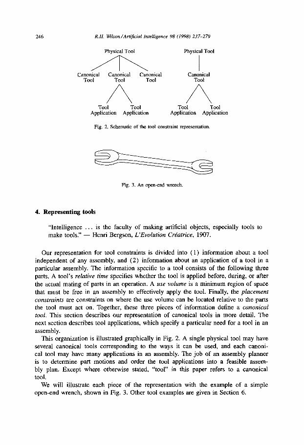

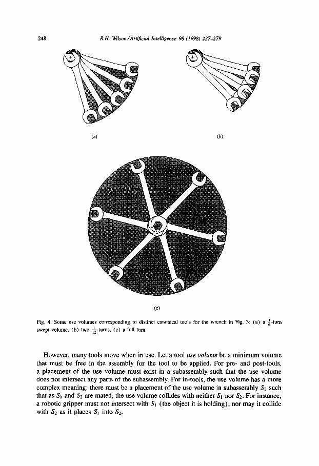


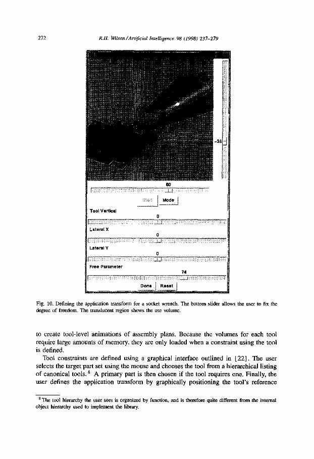
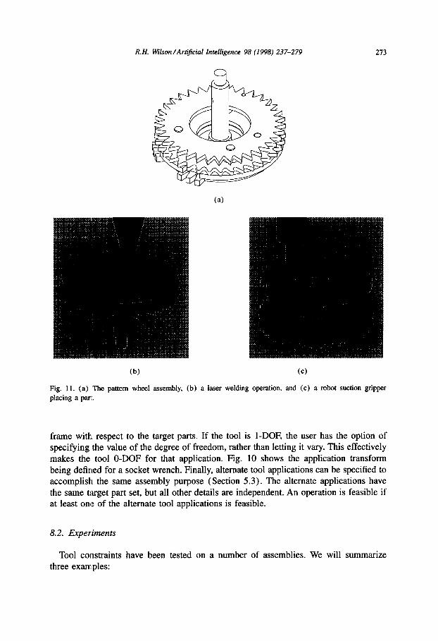


![IS 844-1 (B) (1979): Screwdrivers, Part 1: Technical ... · IS 844-1 (B) (1979): Screwdrivers, Part 1: Technical Supply Conditions(BI-LINGUAL) [PGD 5: Assembly Hand Tools] iS844(arl):1979](https://static.documents.pub/doc/80x56/60ac93d1f0ed7c758e1dca86/is-844-1-b-1979-screwdrivers-part-1-technical-is-844-1-b-1979-screwdrivers.jpg)


