Geometrical representation of the fundamental mode of aGaussian beam in oblate spheroidal coordinates
B. Tehan Landesman
Optical Sciences Center, University of Arizona, Tucson, Arizona 85721
Received March 7, 1988; accepted August 4, 1988
A new geometrical model for the fundamental mode of a Gaussian beam is presented in the oblate spheroidalcoordinate system. The model is an interpretation of a Gaussian amplitude wave function, which is an exactsolution of the scalar Helmholtz equation. The model uses the skew-line generator of a hyperboloid of one sheet asa raylike element on a contour of constant amplitude. The geometrical characteristics of the skew line and theconsequences of treating it as a ray are explored in depth. Finally, the skew line is used to build a nonorthogonal co-ordinate system that permits straight-line propagation of a Gaussian beam in three-dimensional space.
INTRODUCTION
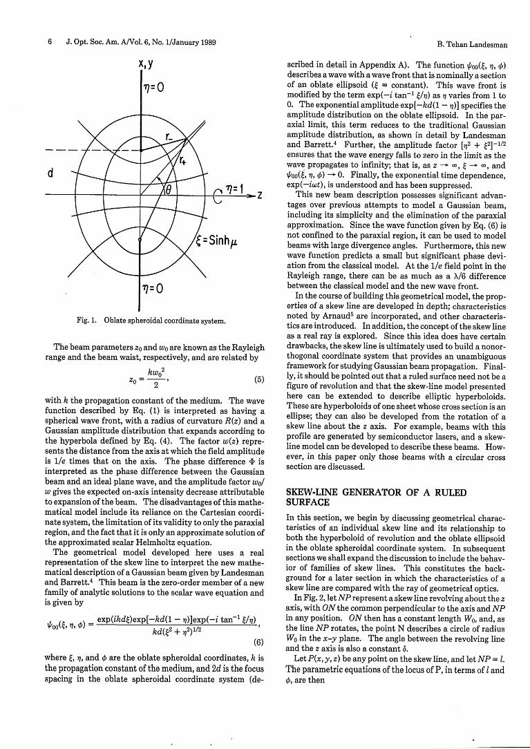
In the past, depictions of the fundamental mode of a propa-gating Gaussian beam consisted of both mathematical de-scriptions of the wave function and geometrical interpreta-tions of these descriptions. The mathematical model usedmost frequently is the one introduced by Kogelnik and Li,'which is only an approximate solution of the scalar waveequation and is expressed in the Cartesian coordinate sys-tem. Other authors2-4 have used the oblate spheroidal coor-dinate system, shown in Fig. 1, to express the propagation ofa Gaussian beam because of the simplicity of modeling acontour of constant amplitude in the beam as a hyperboloidof one sheet, which is one of the oblate spheroidal coordinatesurfaces. It is also possible to obtain exact solutions to theHelmholtz equation in this coordinate system, as was shownby Einziger and Raz3 and Landesman and Barrett.4 In thelatter paper, the mathematical model of a Gaussian beamwas extended to include an entire family of analytic solu-tions to the wave equation that possess an amplitude distri-bution that is fundamentally Gaussian. This is the mathe-matical model that is used here to develop a geometricaldepiction of the fundamental mode of a Gaussian beam.
Since Gaussian beams are used in a wide variety of opticalsystems and instruments, a geometrical model of the beam isan absolute necessity for system design and analysis. Ideal-ly, the model should correspond to the mathematical de-scription and interpret it in the light of geometrical optics.Many methods exist for predicting the first-order propertiesof a Gaussian beam as it traverses an optical system. Thosethat are wedded to the mathematical description of Kogel-nik and Li suffer from the approximations inherent in thatwave function as well as from the awkwardness of describingthe beam in the Cartesian coordinate system. A more use-ful, and currently more popular, method is that introducedby Arnaud,5 7 which unites the geometrical constructs of theoblate spheroidal coordinate system with the wave frontsand amplitude contours of the model of Kogelnik and Li. Inparticular, Arnaud used the geometrical concept of a ruledsurface that is produced by the motion of a skew line. Aruled surface is a surface generated by the motion of a
straight line, called a rectilinear generator, in three-dimen-sional space. A hyperboloid of revolution of one sheet, n =constant in the oblate spheroidal coordinate system, is oneexample of a ruled surface, which, in this case, results fromthe rotation of a straight line about an axis that it does notcut. The straight line is therefore skewed to the axis ofsymmetry, the z axis, and is referred to as a skew line. Theskew line lies on the surface of the hyperboloid and is every-where tangent to it.
The skew line has enjoyed some popularity as the basis fora Gaussian beam model because of the simplicity and thewell-behaved nature of a straight line. Arnaud treated acomplex representation of the skew line as a complex raythat obeys the laws of geometrical optics. Further work hassince extended the representation of the fundamental modeof a Gaussian beam by complex rays,8 -'0 a concept thatFelsen"i vigorously disputed. In contrast, a real representa-tion of the skew line leads to an elegant design tool forpredicting the first-order properties of a Gaussian beam inan optical system. This method was introduced by Shack' 2
and later was developed more fully by Kessler and Shack.' 3
All these constructs hinge on a geometrical interpretationof the traditional description of the fundamental mode of aGaussian beam, as given by Kogelnick and Li.' This mathe-matical model is written as
WO k(X2 + y2) X2 + y2
w(, z)) exp -{ kz - (b + kx+ 2 2 yW~,y )=(z) e i2R (z) w2(z) f
The beam parameters z0 and wo are known as the Rayleighrange and the beam waist, respectively, and are related by
kwo 2k~2°0 2 (5)
with k the propagation constant of the medium. The wavefunction described by Eq. (1) is interpreted as having aspherical wave front, with a radius of curvature R(z) and aGaussian amplitude distribution that expands according tothe hyperbola defined by Eq. (4). The factor w(z) repre-sents the distance from the axis at which the field amplitudeis l/e times that on the axis. The phase difference ' isinterpreted as the phase difference between the Gaussianbeam and an ideal plane wave, and the amplitude factor wolw gives the expected on-axis intensity decrease attributableto expansion of the beam. The disadvantages of this mathe-matical model include its reliance on the Cartesian coordi-nate system, the limitation of its validity to only the paraxialregion, and the fact that it is only an approximate solution ofthe approximated scalar Helmholtz equation.
The geometrical model developed here uses a realrepresentation of the skew line to interpret the new mathe-matical description of a Gaussian beam given by Landesmanand Barrett.4 This beam is the zero-order member of a newfamily of analytic solutions to the scalar wave equation andis given by
where , wq, and are the oblate spheroidal coordinates, k isthe propagation constant of the medium, and 2d is the focusspacing in the oblate spheroidal coordinate system (de-
scribed in detail in Appendix A). The function 00Q(, q, )describes a wave with a wave front that is nominally a sectionof an oblate ellipsoid (Q = constant). This wave front ismodified by the term exp(-i tan-' /1,h) as varies from 1 to0. The exponential amplitude exp[-kd(1 - 7)] specifies theamplitude distribution on the oblate ellipsoid. In the par-axial limit, this term reduces to the traditional Gaussianamplitude distribution, as shown in detail by Landesmanand Barrett.4 Further, the amplitude factor [2 + 2]-1/2
ensures that the wave energy falls to zero in the limit as thewave propagates to infinity; that is, as z -0, - , and
iPo(t, , ) - 0. Finally, the exponential time dependence,exp(-iwt), is understood and has been suppressed.
This new beam description possesses significant advan-tages over previous attempts to model a Gaussian beam,including its simplicity and the elimination of the paraxialapproximation. Since the wave function given by Eq. (6) isnot confined to the paraxial region, it can be used to modelbeams with large divergence angles. Furthermore, this newwave function predicts a small but significant phase devi-ation from the classical model. At the le field point in theRayleigh range, there can be as much as a /6 differencebetween the classical model and the new wave front.
In the course of building this geometrical model, the prop-erties of a skew line are developed in depth; characteristicsnoted by Arnaud 5 are incorporated, and other characteris-tics are introduced. In addition, the concept of the skew lineas a real ray is explored. Since this idea does have certaindrawbacks, the skew line is ultimately used to build a nonor-thogonal coordinate system that provides an unambiguousframework for studying Gaussian beam propagation. Final-ly, it should be pointed out that a ruled surface need not be afigure of revolution and that the skew-line model presentedhere can be extended to describe elliptic hyperboloids.These are hyperboloids of one sheet whose cross section is anellipse; they can also be developed from the rotation of askew line about the z axis. For example, beams with thisprofile are generated by semiconductor lasers, and a skew-line model can be developed to describe these beams. How-ever, in this paper only those beams with a circular crosssection are discussed.
SKEW-LINE GENERATOR OF A RULEDSURFACE
In this section, we begin by discussing geometrical charac-teristics of an individual skew line and its relationship toboth the hyperboloid of revolution and the oblate ellipsoidin the oblate spheroidal coordinate system. In subsequentsections we shall expand the discussion to include the behav-ior of families of skew lines. This constitutes the back-ground for a later section in which the characteristics of askew line are compared with the ray of geometrical optics.
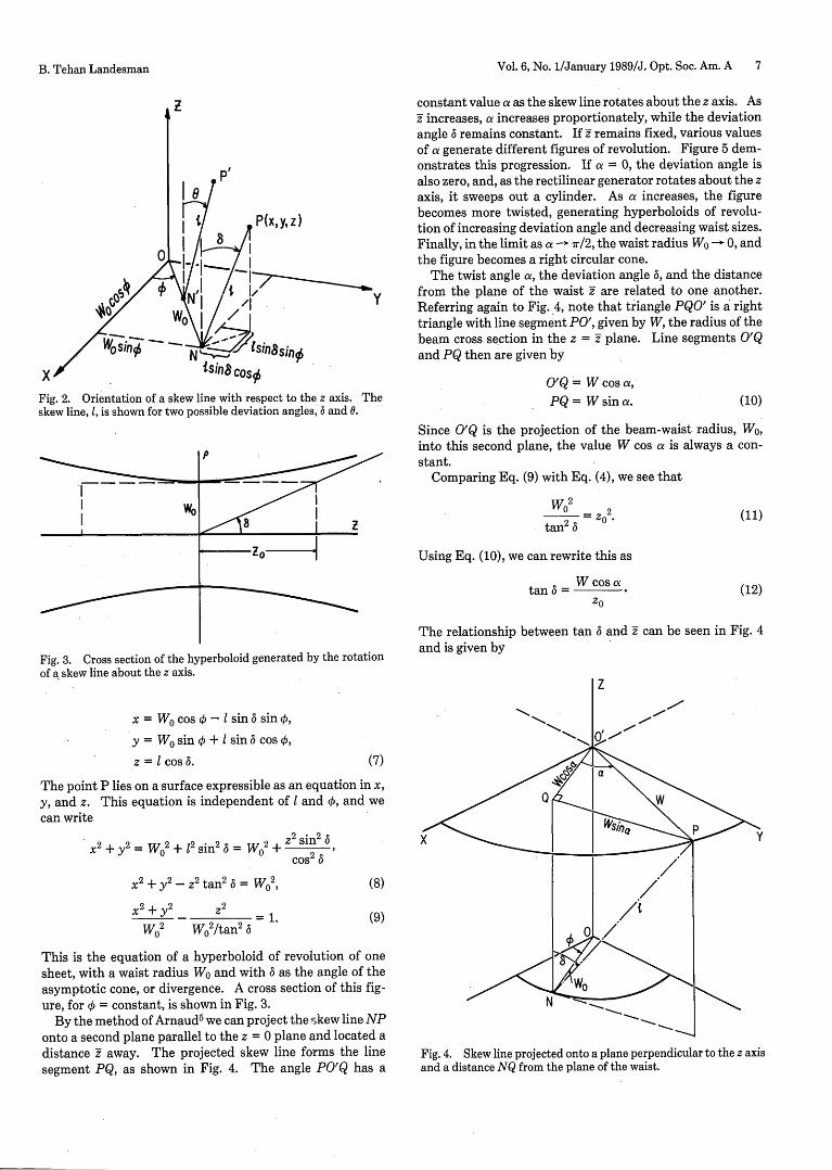
In Fig. 2, let NP represent a skew line revolving about the zaxis, with ON the common perpendicular to the axis and NPin any position. ON then has a constant length W0, and, asthe line NP rotates, the point N describes a circle of radiusW0 in the x-y plane. The angle between the revolving lineand the z axis is also a constant .
Let P(x, y, z) be any point on the skew line, and let NP = 1.The parametric equations of the locus of P in terms of I andX, are then
B. Tehan Landesman
Vol. 6, No. 1/January 1989/J. Opt. Soc. Am. A 7
0I
Z
P'
P(x,y,z)
Isinasino
X .- . 4110 os0
Fig. 2. Orientation of a skew line with respect to the z axis. Theskew line, 1, is shown for two possible deviation angles, 6 and 0.
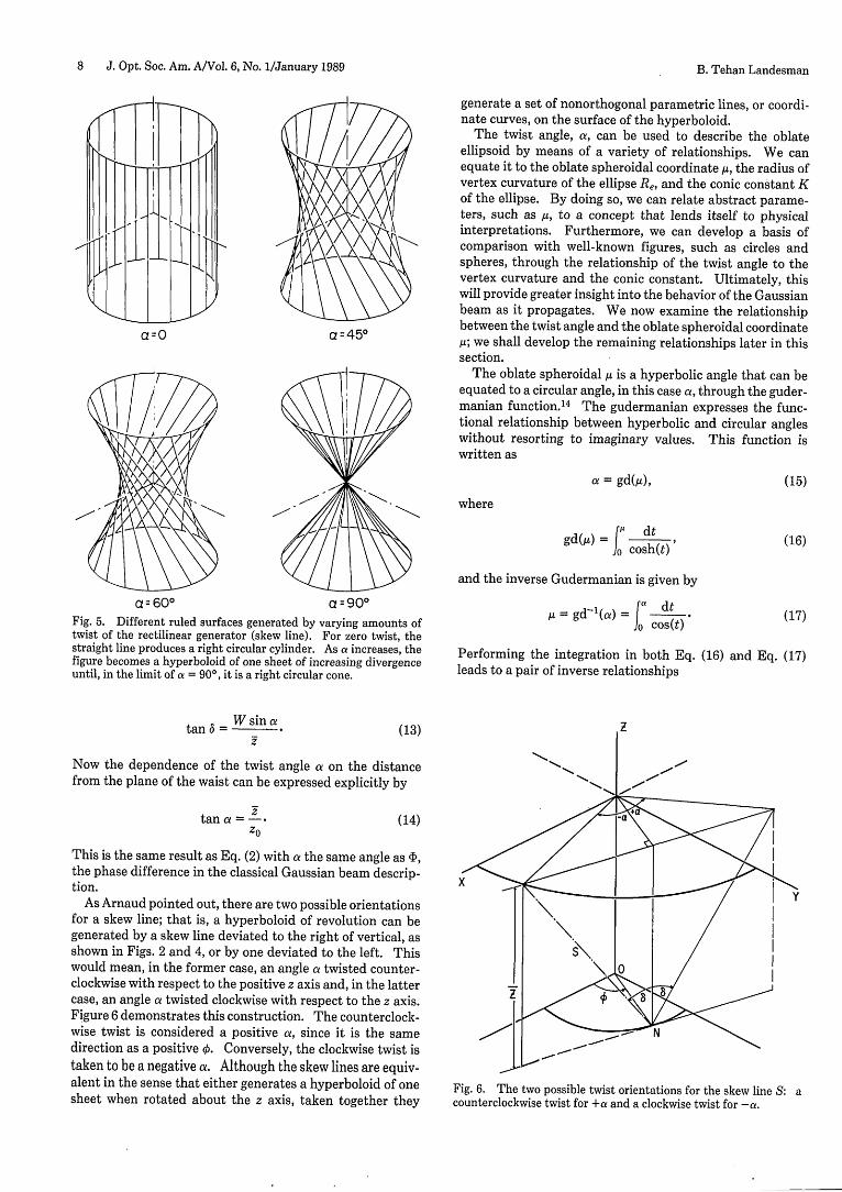
constant value a as the skew line rotates about the z axis. Asz increases, a increases proportionately, while the deviationangle 6 remains constant. If z- remains fixed, various valuesof a generate different figures of revolution. Figure 5 dem-onstrates this progression. If a = 0, the deviation angle isalso zero, and, as the rectilinear generator rotates about the zaxis, it sweeps out a cylinder. As a increases, the figurebecomes more twisted, generating hyperboloids of revolu-tion of increasing deviation angle and decreasing waist sizes.Finally, in the limit as a -> 7r/2, the waist radius W0 - 0, andthe figure becomes a right circular cone.
The twist angle a, the deviation angle 6, and the distancefrom the plane of the waist z are related to one another.Referring again to Fig. 4, note that triangle PQO' is a righttriangle with line segment PO', given by W, the radius of thebeam cross section in the z = z- plane. Line segments O'Qand PQ then are given by
O'Q = W cos a,PQ = W sin a. (10)
woI
-zo -
Fig. 3. Cross section of the hyperboloid generated by the rotationof a skew line about the z axis.
x = W0 cos k - 1 sin 6 sin 0,
y= W0 sino+lsin6cosO,
z = 1 cos 6.
Since O'Q is the projection of the beam-waist radius, Wo,into this second plane, the value W cos a is always a con-stant.
Comparing Eq. (9) with Eq. (4), we see that
tan2 6 -
Using Eq. (10), we can rewrite this as
tan 6 = W cos a zo
The relationship between tanand is given by
(7)
The point P lies on a surface expressible as an equation in x,y, and z. This equation is independent of I and , and wecan write
X2 + y2 = W2 + 12 sin2 = W02 + 2
Cos2
6
X2 + y2- Z2 tan2
6 = Wf2
X2 + Y2 z2 =1.
W02 W02 /tan2 6
(8)
(9)
This is the equation of a hyperboloid of revolution of onesheet, with a waist radius Wo and with 6 as the angle of theasymptotic cone, or divergence. A cross section of this fig-ure, for 0 = constant, is shown in Fig. 3.
By the method of Arnaud 5 we can project the skew line NPonto a second plane parallel to the z = 0 plane and located adistance z away. The projected skew line forms the linesegment PQ, as shown in Fig. 4. The angle PO'Q has a
(11)
(12)
6 and z can be seen in Fig. 4
Z
Y
Fig. 4. Skew line projected onto a plane perpendicular to the z axisand a distance NQ from the plane of the waist.
l-
B. Tehan Landesman
8 J. Opt. Soc. Am. A/Vol. 6, No. 1/January 1989
generate a set of nonorthogonal parametric lines, or coordi-nate curves, on the surface of the hyperboloid.
The twist angle, a, can be used to describe the oblateellipsoid by means of a variety of relationships. We canequate it to the oblate spheroidal coordinate u, the radius of
l l fl A)\ 8//\/ /} vertex curvature of the ellipse Re, and the conic constant Kof the ellipse. By doing so, we can relate abstract parame-ters, such as az, to a concept that lends itself to physicalinterpretations. Furthermore, we can develop a basis ofcomparison with well-known figures, such as circles andspheres, through the relationship of the twist angle to thevertex curvature and the conic constant. Ultimately, thiswill provide greater insight into the behavior of the Gaussianbeam as it propagates. We now examine the relationship
a=O a=451 between the twist angle and the oblate spheroidal coordinatea 0 O a 450 s; we shall develop the remaining relationships later in this
section.The oblate spheroidal IA is a hyperbolic angle that can be
equated to a circular angle, in this case a, through the guder-manian function.'4 The gudermanian expresses the func-tional relationship between hyperbolic and circular angles
A without resorting to imaginary values. This function iswritten as
and the inverse Gudermanian is given by
a c 600 a 90° 1A = = dt (15)Fig. 5. Different ruled surfaces generated by varying amounts of COW)dlc) *(7twist of the rectilinear generator (skew line). For zero twist, thestraight line produces a right circular cylinder. As a increases, the Performing the integration in both Eq. (16) and Eq. (17)figure becomes a hyperboloid of one sheet of increasing divergence last aro nes eainhpuntil, in the limit of a = 90°, it is a right circular cone. last aro nes eainhp
tan = sin a = d (13) X
Now the dependence of the twist angle a on the distance em i g nfrom the plane of the waist can be expressed explicitly by C s -
tan = Z . (14) a
This is the s am e result as Eq. (2 ) with st the same angle as ,the phase difference in the classical Gaussian beam descrip- thtion. X
As Arnaud pointed out, ther e seetwo possible orientations l t a p o i rfor a skew line; that is, a hyperboloid of revolution can begenerated by a skew line deviated to the right of vertical, asshown in Figs. 2 and 4, or by one deviated to the left. This S\would mean, in the former case, an angle r twisted counter- clockwise with respect to the positive z axis and, in the latter -|> p7 case, an angle ae twisted clockwise with respect to the z axis. IFigure 6 demonstrates this construction. The counterclock-wise twist is considered a positive , since it is the samed irec tion as a positive 0. Convers ely, the clockwise twist istaken to be a negative a. Although the skew lines are equiv- alent in the sense that either generates a hyperboloid of one Fig. 6. The two possible twist orientations for the skew line S: asheet when rotated about the z axis, taken together they counterclockwise twist for +a and a clockwise twist for -.
B. Tehan Landesman
Vol. 6, No. 1/January 1989/J. Opt. Soc. Am. A 9
P
Fig. 7. Cross section of one confocal oblate ellipse and hyperbola.Their common foci are spaced at 2d; K is the conic constant of theellipse, and Re is the radius of the vertex curvature of the ellipsealong the semiminor axis.
a = 2 tan-'(el) - r/2 (18a)
and
= ln tan( + °). (18b)
Expanding the tangent function leads to
e= 1 + sin a (19a)cos a
and
-s 1-sin a (19b)cos a
We can now derive a more explicit functional relationshipbetween /i and a. Using the definitions of the oblate sphe-roidal coordinate t given in Appendix A and the exponentialdefinitions of sinh ,u and cosh tL, we can write
t = sinh A = tan a,(W2 + 1)1/2 = cosh A = 1/cos a,
tanh te = sin a. (20)
Using these expressions, we can rewrite the parametricequations for the oblate spheroidal system as
d sin 0 cos 0cos a
d sin 0 sin 0cos a
z = d tan a cos 0. (21)
We can conclude from this analysis that the skew line and itscorresponding twist angle can be used in describing the ob-late spheroidal coordinate system in which we have de-scribed a new mathematical model for a propagating Gauss-ian beam. Therefore they should be equally useful in de-scribing the beam itself.
In Eq. (9), varying Wo and 6 generates a family of hyperbo-
loids related by their common focus. As is shown in Fig. 2,each member of this family possesses its own rectilineargenerator N'P' and deviation angle 0, but all members havecommon perpendiculars to the z axis, ON' = W'cos a. Letthe length of the skew line N'P' = remain constant for all 0;then the parametric equations of the locus of P'(x', y', z') aresimilar to Eqs. (7), and we can write
x' = W' cos 0 = W' cos a cosq -l sin 0 sin,
y'= W' sino = W' cosa sino + I sin0 cosX,
z' = cos 0. (22)
We wish to find the surface containing P', which is theendpoint of all skew lines having the same length 1 and twista from the plane of the waist. This surface will be indepen-dent of 0 and A, and we can write
X2 + y'
2 = W2 COS2 a + 12 sin2 6,
W2 = W2 COS 2 a + 12(1 - Z 2/12,.
After some algebraic manipulation, Eqs. (23) become
+ 2 = 1.12/Si1 2 a 12
(23)
(24)
This is the equation of an ellipse at a constant distance 1, asmeasured along a skew line, from the plane of the waist of thehyperboloid of revolution. A family of skew lines with con-stant length 1 is shown in Fig. 7. The arc PA lies on theellipse specified by the constant angle a. This family isdiscussed further in a subsequent section. Since the param-eter l/sin a > I for a <r/2, this particular ellipse has foci anda semimajor axis located in the plane z = 0 and is a figure ofrevolution about the z axis. As such, it is referred to as anoblate ellipsoid.
Equations (9) and (22) represent specific examples ofmore-general families of hyperboloids of revolution of onesheet and oblate ellipsoids that are orthogonal. The generalequation for a hyperboloid of revolution is given by
- + = 1,
ah2 ah2-d
whereas for an ellipse it is
p2 + z222 +e - =1,
a, 2 a, 2 -d
ah < d,
ae > d,
(25)
(26)
where p2= x
2+ y
2. For a figure of revolution about z, thefocus describes a ring of diameter 2d. The parameters aeand ah, shown in Fig. 8, refer to the semimajor axis of theellipse and the waist radius of the hyperboloid, respectively.
Comparing Eqs. (22) with Eq. (26), we note that
ae2 22 = 12 = - d2.sin a
This expression can be reduced to
1 = d tan a,
and Eq. (26) becomesP2 z2
_ + =1.
d2 /cos2 a d2 tan2 a
(27)
(28)
(29)
Note that the twist angle a determines not only the length ofthe skew line I but also the specific ellipsoid in a family of
B. Tehan Landesman
10 J. Opt. Soc. Am. A/Vol. 6, No. 1/January 1989 B. Tehan Landesman
the twist angle in terms of the conic constant. These expres-sions are
2 KCOS = 1
2 1sin a= K 1
A general expression for the hyperboloid of revolution canbe obtained by comparing Eqs. (25) and (9). First, note that
Wo2 ah2ah - d 2
=- 0 -- ahtan 2 6 tan 2(35)
where
ah = d sin 6. (36)
Since 6 is a specific deviation angle and represents allpossible such angles between 0 and ±r/2, replacing 6 by 0produces a family of hyperboloids expressed by
p2 z22_ =1
d2 sin2 0 d2 cos2 6(37)
In this formulation, the Rayleigh range for any specific hy-perboloid is given by
zo = d cos 6,and the expression for the waist radius has the form
wo = d sin .
(38)
X L -
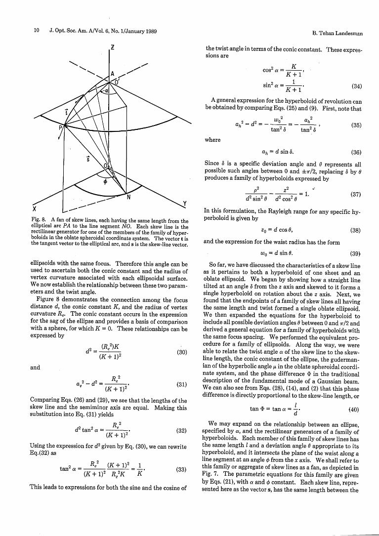
Fig. 8. A fan of skew lines, each having the same length from theelliptical arc PA to the line segment NO. Each skew line is therectilinear generator for one of the members of the family of hyper-boloids in the oblate spheroidal coordinate system. The vector t isthe tangent vector to the elliptical arc, and s is the skew-line vector.
ellipsoids with the same focus. Therefore this angle can beused to ascertain both the conic constant and the radius ofvertex curvature associated with each ellipsoidal surface.We now establish the relationship between these two param-eters and the twist angle.
Figure 8 demonstrates the connection among the focusdistance d, the conic constant K, and the radius of vertexcurvature Re. The conic constant occurs in the expressionfor the sag of the ellipse and provides a basis of comparisonwith a sphere, for which K = 0. These relationships can beexpressed by
(Re2)Kd2 =(e )K(30)(K+ 1)2
and
(K + 1)2 (31)
Comparing Eqs. (26) and (29), we see that the lengths of theskew line and the semiminor axis are equal. Making thissubstitution into Eq. (31) yields
d2 tan 2 a = e (32)(K + 1)2
Using the expression for d2 given by Eq. (30), we can rewriteEq.(32) as
Re 2 (K + 1)2 1tan2 a = (33)
(K + 1)2 Re2K th (33)
This leads to expressions for both the sine and the cosine of
(39)
So far, we have discussed the characteristics of a skew lineas it pertains to both a hyperboloid of one sheet and anoblate ellipsoid. We began by showing how a straight linetilted at an angle 6 from the z axis and skewed to it forms asingle hyperboloid on rotation about the z axis. Next, wefound that the endpoints of a family of skew lines all havingthe same length and twist formed a single oblate ellipsoid.We then expanded the equations for the hyperboloid toinclude all possible deviation angles 0 between 0 and 7r/2 andderived a general equation for a family of hyperboloids withthe same focus spacing. We performed the equivalent pro-cedure for a family of ellipsoids. Along the way, we wereable to relate the twist angle a of the skew line to the skew-line length, the conic constant of the ellipse, the guderman-ian of the hyperbolic angle ,u in the oblate spheroidal coordi-nate system, and the phase difference 4 in the traditionaldescription of the fundamental mode of a Gaussian beam.We can also see from Eqs. (28), (14), and (2) that this phasedifference is directly proportional to the skew-line length, or
tan 4b = tan a = --d (40)
We may expand on the relationship between an ellipse,specified by a, and the rectilinear generators of a family ofhyperboloids. Each member of this family of skew lines hasthe same length I and a deviation angle 0 appropriate to itshyperboloid, and it intersects the plane of the waist along aline segment at an angle from the x axis. We shall refer tothis family or aggregate of skew lines as a fan, as depicted inFig. 7. The parametric equations for this family are givenby Eqs. (21), with a and constant. Each skew line, repre-sented here as the vector s, has the same length between the
.7
(34)
Vol. 6, No. 1/January 1989/J. Opt. Soc. Am. A 11
elliptical arc PA and the line segment ON. The intersectionof each successive skew line with segment ON is a distance dsin 0 from the origin, where 0 is the deviation angle of the newskew line and represents another member in the family ofhyperboloids. Furthermore, each skew line is perpendicularto the elliptical arc. This is intuitively true, since each skewline lies on a hyperboloid, the orthogonal surface to an oblateellipse. A more detailed proof is given in Appendix B.
GEOMETRICAL INTERPRETATION OFexp(-i tan-' s/n)Both the classical mathematical model of a Gaussian beamgiven in Eq. (1) and the new model of Eq. (6) include arctan-gent factors in their exponential phase terms. A geometri-cal interpretation of these terms would provide much usefulinsight into the nature of a phase front as it propagates. Inthe case of the term exp(-i tan-' s/n), a simple geometricalexplanation does exist.
Figure 9 displays the skew line PN once again at a devi-ation angle 0, along with the attendant elliptical arc PA.Further, the figure designates two planes, one perpendicularto the z axis at the point O' and the other perpendicular tothe z axis at point A. The O' plane intersects the hyperbolaof deviation angle 0 in a circle with radius p = PO'. The Aplane is the tangent plane to this oblate ellipsoid at the point(0, 0, A). The distance along the z axis between these twoplanes is the sag of ellipse. As demonstrated earlier in thispaper, the distance AO must be the length of the skew line, dtan a. Therefore the equation for the sag is given by
sag = d tan a(1 - cos 0). (41)
The distance from the plane O' to plane A along the skewline, designated Al in the drawing, is simply sag/cos 0, or
d tan a (1-cos 0).cos 0
(42)
The increased length of the skew line translates directly intoan increase in the twist angle a. We shall refer to thisincreased twist as Aa. The entire length of the skew linefrom the point N until it intersects the plane A is given by 1 +Al. Given in terms of the twist angle, this is
I + Al = d tan(a + Aa). (43)
Substituting the value of d tan a for 1 and Eq. (42) for Alyields
d tan a a + dtan a = tanadtan(a + Aa). (44)cos 0
This reduces to
tan a = tan(a + Aa). (45)cos 6
From the definition of the oblate spheroidal coordinates, wecan substitute t and n for the terms tan a and cos 0, respec-tively, and Eq. (45) becomes
- = tan(a + Aa). (46)77
Finally, by taking the arctangent of both sides, we obtain
tan-' O/' = a + Aa. (47)
z
Fig. 9. The differential change in twist angle, Aa, corresponds tothe sag of the elliptical arc, PA, as measured along the skew line.This distance is given by d/n - d§.
Some algebraic manipulation is required to obtain an ex-pression for Aa in terms of t and -q. This equation is
Aa = tani[ M - )] (48)
The entire exponential phase factor exp(-i tan-' /1-q) canthen be rewritten as
exp(-i tan-' t/) = exp[-i tan-' t - tan-' ( (49)
The difference between the exponential arctangent phaseterm of the classical Gaussian beam mathematical modeland the one represented by Eq. (6) is the phase term attrib-utable to Aa.
The exponential factor exp(-i tan-' s/1n) can be interpret-ed as representing the difference in phase that a wave distur-bance would undergo in traveling along the skew line in thetime required for the edge of the beam to advance to the zdistance represented by plane A. In other words, as thebeam propagates, its center passes plane A at time tj. At alater time t2 , the beam edge will pass plane A, and in the timet2 - tj, the phase of the beam will have changed by Aa.Another interpretation is that of an off-axis, or wave-front,error; that is, a wave front is ideally a section of an oblateellipse, but off axis it deviates from the ideal by an amountgiven by Aa/k. For example, a = 450 at the Rayleigh rangeof any Gaussian beam. In the case of a highly divergentbeam with a 0 of 100 at the 1/e field point, the wave front hasa X/8 deviation from a perfectly oblate ellipse at the 1/eradius at the Rayleigh range. In the limit as 71 - 0, the skewline collapses to the plane of the waist, and the exponentialfactor equals exp(-i7r/2). Since the skew line normally ex-tends on either side of the waist, and since the entire linecollapses into the beam waist as 77 - 0, the overall phase
B. Tehan Landesman
12 J. Opt. Soc. Am. A/Vol. 6, No. 1/January 1989 B. Tehan Landesman
change is 180°. This is consistent with the 180° phase shiftexperienced by a general light wave in passing through afocus. Finally, we note that the sign of the phase term issuch that a surface of constant phase will be curved towardthe plane of the waist and inside the figure of the oblateellipse. Although it is tempting to believe that this makesthe wave front more nearly spherical, the opposite is true.An oblate ellipse is always curved inside the figure of asphere whose radius corresponds to the vertex curvature ofthe ellipse.
THE SKEW LINE AS A RAY
We have pointed out a number of interesting features ofindividual skew lines as well as of fans of skew lines. Inparticular, we note that the relationship between an ellipti-cal arc and a fan of skew lines demonstrates three character-istics of wave fronts and their trajectories. First, the spatialseparation as measured along any skew line of the fan be-tween an elliptical arc and the plane of the waist remainsconstant. This statement can be generalized to include theseparation between any two elliptical arcs that are differenttwist angles and are perpendicular to the same family ofskew lines. Second, successive elliptical arcs are perpendic-ular to a skew line, prompting comparisons between succes-sive arcs on a wave front and the wave front's orthogonaltrajectory, or ray. Finally, the skew line is a straight line, asis the current geometrical-optics model ray in a homoge-neous medium.
Still further, we can prove that, when a ray with a skew-line trajectory is reflected from an oblate ellipsoidal mirror,the reflected ray also possesses a skew-line trajectory on thesame hyperboloid as the incident ray. Proof of this requiresa three-dimensional vector analysis and can be found inAppendix C. This particular characteristic of the skew linefinds a useful application in modeling ray behavior in anoptical resonator. The continuum of all such skew raysforms the hyperbolic amplitude contours. Such an envelopeof rays was discussed by Bykov and Vainshtein,15 Kahn,16
and Stein.' 7
All the above results demonstrate that the skew-line mod-el of a propagating Gaussian beam, as expressed in Eq. (6),possesses strong parallels with the theorems of geometricaloptics. However, two traits of a skew line prevent it frombeing defined as a ray. The first is that the skew line is notthe gradient of the wave described by Eq. (6). Second, if askew line is to be seen as a ray, the possibilities of its twodifferent orientations must be considered equally likely.One way to include both positive and negative (counter-clockwise and clockwise) twists in the geometrical descrip-tion of a Gaussian beam is to treat the two skew lines as unitcoordinate vectors, t and , which, together with the unitvector , form a nonorthogonal coordinate system.
The skew-line fan of Fig. 7 can be repeated for a counter-clockwise twist, and the resultant figure forms a mirror im-age of the clockwise fan. This is demonstrated in Fig. 10.The skew line s of Fig. 7 reappears as pointed in theopposite direction, and the tangent vector to the ellipse, t,has been renamed . The skew line for a positive a, or acounterclockwise twist, is az. Figure 10 sketches the skew-line fans for a few discrete deviation angles. In actual prac-
X
Z Z
Clockwise Counter ClockwiseFig. 10. Skew-line fans for a clockwise twist (-a) and a counter-clockwise twist (+a), for discrete skew lines. The skew lines aredenoted as the vectors v and a, and is the tangential vector to theelliptical arc. The figures are mirror images of each other.
tice, the fans are surfaces called right conoids, as shown inFig. 11. All these conoids are ruled surfaces; they areformed by the motion of a straight line, the skew line, inthree-dimensional space. Together with the oblate ellip-soid, these surfaces form three coordinate surfaces in a non-orthogonal coordinate system, which we now explore. Anexcellent discussion of general three-dimensional curvilin-ear coordinate systems can be found in Stratton's Electro-magnetic Theory.1 8
NONORTHOGONAL COORDINATE SYSTEMThe coordinate system whose unit base vectors are shown inFig. 12 consists of two right conoids, one left-handed and theother right-handed, whose axis of symmetry is the z axis, andan oblate elliposid with a focal ring of radius d in the x-yplane. The right-handed conoid is the counterclockwiseskew-line fan (+a), so named because the skew lines seem tosweep in the direction of the fingers of the right hand withthe thumb pointed in the direction of the positive z axis as avaries from -7r/2 to +r/2. Similarly, the left-handed conoidis the clockwise skew-line fan (-a). This time, as a variesfrom +7r/2 to -7r/2, the skew lines sweep in the direction ofthe fingers of the left hand when the thumb is pointed in thedirection of the positive z axis. The coordinate angle 0 is thedeviation angle of the skew line with respect to the z axis.This coordinate system is not orthogonal, since the coordi-nate surfaces do not intersect at right angles.
The parametric equations for this system are
d sin 0 cos[ 2 vx(u, v, ) =
-Cos2
d sin 0 sin[ + ly(u, v, ) = c 1
u - vz(u, vs ) = d cos 0 tan[ 2 ' (50)
Vol. 6, No. 1/January 1989/J. Opt. Soc. Am. A 13
Fig. 11. Continuous surfaces generated by the skew-line fans of Fig. 10. The left-hand drawing represents a left-handed right conoid
corresponding to a clockwise twist, and the right-hand drawing represents a right-handed right conoid corresponding to a counterclockwise
twist. In both drawings, the lower circle represents the plane of the waist, and the upper circle represents an oblate ellipsoid a distance from the
waist. The vertical dashed-dotted line represents the z axis in both drawings.
Fig. 12. Unit base vectors a, D, and 0 for a nonorthogonal coordinate system. The two conoids join in an elliptical arc in the left-hand drawing.
Their junction in the plane of the waist is shown in the right-hand drawing.
B. Tehan Landesman
14 J. Opt. Soc. Am. A/Vol. 6, No. 1/January 1989
where
u 0+ (51)
and
v=0-a. (52)
Note that these equations strongly resemble the paramet-ric equations of the oblate spheroidal coordinate system.For that system, we discussed surfaces on which one of thecoordinate variables was constant and the unit base vectors,I, , and A, were the normals to these surfaces. For the sakeof simplicity, we shall not discuss the surfaces on which thecoordinates u, v, and are constant. Instead we shall outlinethe unit base vectors, , v, and , as the vectors tangent to theright-handed conoid, the left-handed conoid, and the oblateellipsoid, respectively.
The position vector r to any point in the three-dimension-al space is given by
r = x(u, v, 0)1 + y(u, v, 0)5 + z(u, v, 0)%, (53)
where , 5, and are the unit base vectors in the Cartesiancoordinate system. A differential change in r, due to smalldisplacements along the coordinate curves, is expressed by
dr = -r du +-dv + do. (54)
If one moves a unit distance along any one of the coordinatecurves, the change in r is directed tangentially along thatcurve and has a magnitude of 1. The vectors
OrauOrau
Or
OrOu
Or
|=- (55)Or
are the unit base vectors for the coordinate system. For thenonorthogonal system here, these are
a = (-sin sin v)t + (sin cos v)5 + (cos 0)%,= (-sin sin u)l + (sin cos u)5 + (cos 0)%,
cos cos 0 + cos sin0 sin sin[(u-u)/2](1 - a2)1 /2 (1 - a2)11 2 (1 _ a2)1 /2
(56)
where a = sin 6 cos[(u-v)/2J. Figure 12 shows these vectorsat two different points in space.
In the left-hand drawing of Fig. 12, the observation pointresides on an oblate ellipse some distance from the plane ofthe waist. The vectors a, , and are shown as tangents tothe two conoids and the oblate ellipsoid, respectively. Theconoidal surfaces meet in an arc on this ellipsoid and are
separated in the plane of the waist by the acute angle 2a,where a is the twist angle associated with the ellipsoid.Likewise, the right-hand drawing in Fig. 12 shows the obser-vation point in the plane of the waist with the associated unitbase vectors. The conoids meet along a line segment in thewaist and are separated on an oblate ellipsoid by the acuteangle 2a.
The most useful aspect of these unit vectors is their rela-tionship to the unit vectors of the oblate spheroidal system.Starting with Eqs. (56), some algebraic manipulation leadsto the relations
a-Li2(1 - al
a+2a
X= -a. (57)Clearly, the connection between the two systems is a simpleone, with the useful result that two straight-line vectors, and , can synthesize the tangential vectors, and X, to twocurves in space, a hyperbola and a circle.
Although using a nonorthogonal coordinate system seemsan unnecessary complication of the geometrical model, thisparticular coordinate system has some advantages over theoblate spheroidal coordinate system in describing a propa-gating Gaussian beam. Specifically, a wave-front surfacenormal can be obtained from the difference between thetwo skew-line vectors, a and . This gives us the advantageof using straight-line trajectories to predict the beam's be-havior on propagation without neglecting the proper de-scription of a wave-front normal. Also, the nonorthogonalsystem is allied so closely with the oblate spheroidal coordi-nate system that straight-line propagation can be used with-out deviating from an exact mathematical description of thebeam.
CONCLUSION
A simple but precise geometrical interpretation of the alter-native mathematical description of the zero-order mode of apropagating Gaussian beam, represented by Eq. (6), is pre-sented in this paper. Both the geometrical and the mathe-matical models are expressed in the oblate spheroidal coor-dinate system, and it is one of the coordinate surfaces, thehyperboloid of one sheet, of this system that forms the basisof the geometrical configuration. Specifically, the hyperbo-loid is an example of a ruled surface that can be generated bya straight line, skewed to the z axis, rotating about the z axis.
The properties of an individual skew line as well as thoseof families of skew lines have been discussed in detail. Webegan by describing the hyperboloid generated by the skewline and then related the skew line to the oblate ellipsoidwith the twist angle concept. This relationship exists in thedefinition of the conic constant of the ellipse, the guderman-ian of the hyperbolic angle ,4 in the oblate spheroidal coordi-nate system, and in the length of the semiminor axis of theellipse. Furthermore, the length of the skew line from theplane of the waist to an ellipsoidal surface is directly propor-tional to the tangent of the twist angle.
One intriguing aspect of both the new and the traditional
B. Tehan Landesman
Vol. 6, No. 1/January 1989/J. Opt. Soc. Am. A 15
models of the Gaussian beam is the presence of a pure phaseterm that has an arctangent dependence. In the traditionalmodel, the phase term is exp(-ia), where a is the twist angledescribed in an earlier section. The interpretation of thisterm is a phase difference between the actual wave front anda plane wave. In Eq. (6), however, the term appears asexp(-i tan-' a/-q), which represents the sag of the obIateellipse as measured along the skew line.
The properties of an individual skew line can be expandedto include families of these lines, and it is in consideration ofone type of family in particular, the fan, that strong parallelswith the ray of geometrical optics can be found. A fan ofskew lines intersects any oblate ellipse in an arc, and eachmember of the fan is perpendicular to this arc. Further, thespatial separation remains constant between two successivearcs, as measured along any member of the fan, much likethe constant separation between any two successive wavefronts, as measured along their orthogonal trajectories orrays. Proceeding with the idea of a skew line as a ray, it isshown in Appendix' C that a ray with skew-line trajectoryreflected from a mirror that is a section of an oblate ellipsoidyields its opposite member, that is, a ray with the skew-linetrajectory of the same hyperboloid and an equal, but oppo-site, twist angle.
Finally, we pointed out the failure of the skew line as a ray.Specifically, the skew line is not the gradient of the wavedescribed by Eq. (6), and since there are two possible orien-tations of each skew line, they must be considered equallylikely. It was then'suggested that the real power of theskew-line model might be shown by using both orientationsas two components in a nonorthogonal system, and the de-tails of this system were discussed. Instead of creating anunnecessary complication of the issue, the use of both ofthese skew-line vectors makes straight-line propagation pos-sible, while providing the unambiguous framework neces-sary for locating points in space, identifying the wave-frontnormal, and defining deformed surfaces such as aberratedwave fronts.
APPENDIX A: THE OBLATE SPHEROIDALCOORDINATE SYSTEM
The oblate spheroidal coordinate system, shown in Fig. 1, isformed by rotating a system of mutually orthogonal ellipsesand hyperbolas about the minor axis of the ellipse. The zaxis is the axis of rotation, and the focus is a ring of radius din the x-y plane. The parametric equations relating theoblate spheroidal coordinate system to Cartesian coordi-nates are
x = d cosh A sin O cosX,y = d cosh A sin O sin 0,z = d sinh A cos 0,
with either
0•6i7r, 0•t<A , 0 <ck2ir
or
(Al)
x = d(1 + 42)1/2(1 - 72)1/2 COS a,
y = d(1 + 42)1/2(1 - 72)1I2 sin ,
z = dn,
with either
-l1 S 7<1, 0 < t< , .O O0 <27r
(A3)
(A4a)
or-0 < 1, -X< <, 0 < <.2r. (A4b)
In the oblate system, the surface ki = constant > 0 is anoblate ellipsoid with a major axis of length 2d cosh , andminor axis of length 2dlsinh A. The surface t = 0 is acircular disk of radius d centered at the origin in the x-yplane. The surface 1| = constant < 1 is a hyperboloid ofrevolution of one sheet whose asymptotes pass through theorigin, inclined at an angle 0 = cos-i q to the z axis. Thedegenerate surfaced, = 1 is the z axis. The surface - = 0 isthe x-y plane, except for the circular disk t = 0. Finally, thesurface 0 = constant is the azimuthal plane containing the zaxis. The angle k is measured from the x-z plane.
APPENDIX B: PROOF THAT AN ARC OF ANOBLATE ELLIPSE IS PERPENDICULAR TO ITSATTENDANT SKEW-LINE FAN
The parametric Eqs. (Al) describe the arc PA in Fig. 8 forthe case in which a and k are held constant. These equa-tions are therefore functions of 0 only and have the form
d sin 6x (6) =cos cOS( 4 a),
sin 6y(6) = d s sin(q5 + a),cos a
z(6) = d tan a cos 0, (BI1)
where we have made the substitutions for sinh A and cosh Atgiven in Eqs. (20).
The angle 0 is measured from the x axis to the line seg-ment ON in the plane of the waist only. The azimuthalangle in any other plane perpendicular to the z axis is givenby k i a. The angle a determines the ellipse of interest andthe length of the skew line. The tangent to the elliptical arcis given by
t Ox() y() 9 + z() ao ao~ 5+ a (B2)
where x, 5, and 2 are Cartesian unit vectors. Differentiatingwith respect to 0 yields
t d cos 0 cos(, d: a) x +d cos 0 sin(o + a) ,cos a cos a
-d tan a sin 0 2. (B3)
(A2a) The + for cc determines whether the arc in question is for acounterclockwise (+a) twist or a clockwise (-a) one.
The vector representation for a skew line s is given by
s = (x'-x)x + (y'-y) + (z'-z)2.0 0 7r/2, -- S p < , 0 0 2r. (A2b)
In the oblate case, we let t = sinh At and 7t = cos 0. The
parametric equations then becomeIn the plane of the waist, a = 0, and the parametric Eqs. (Bi)become
(B4)
B. Tehan Landesman
16 J. Opt. Soc. Am. A/Vol. 6, No. 1/January 1989
x = d sin cos 0,y = d sin sin ,z = 0. (B5)
On the elliptical arc,.the coordinates of a point are x', y' andz' and are described by the parametric equations
X'(6) = d sin 0 cos(t a)cos a
y'(0) d sin 0 sin( a)cos a
z'(0) = d tan a cos .
Substituting Eqs. (B5) and (B6) into Eq. (B4) gives
(B6)
s = (d tan a sin 0 sin ¢)x + (d tan a sin 0 cos 0)9+ (d tan a cos )2. (B7)
The magnitude of s is d tan a, the length of the skew line.Note that, regardless of the choice of a, the magnitudes ofthe x and 5 components are opposite in sign.
Taking the dot product of t and s leads to
t s = -d2 tan sin cos (o ± )si cos a
d tan sin cos 0sin( + a)cos a
X cos o - d2 tan2 a sin 0 cos 0. (B8)
spheroidal coordinate system. The three unit normals forthis system are given by
= ((1 - 22)1 cos(¢ i oa)5 + ((1 - A2)i/2 sin(q ± a)5(~2 + 2)1/2 (W + 02)1/2
where x, , and 2 are the unit vectors in the Cartesian coordi-nate system. We have made use here of the definition of theazimuthal angle 0 ± a in a plane other than the plane of thewaist. Furthermore, we shall use the definitions for tan aand cos a given in Eq. (20).
Since the incident ray has the same trajectory as a skewline, its vector representation can be found from Eq. (B7).For a skew-line trajectory with a clockwise twist (-a), theincident ray is the unit vector
a = (sin 0 sin 0)1 - (sin 0 cos 0)5 + (cos )2.Simplifying terms results in
t s = d2 tan a sin cos 0 [sin cos( + a)cos a
+ cos k sin(o ± a) - sin a]. (B9)
Next, we expand the term in brackets to find that
t s - sin 0 cos 0 [sin (cos cos a - sin 0 sin a)cos a
± cos (sin cos a + cos sin a) - sin a]
d a a sin 0 cos [sin a(tsin2 g * cos2 )- sin a],
(B10)
and, finally,
t - S = 0. (B11)
Therefore the skew line is perpendicular to the elliptical arcPA.
In order to find the plane containing t and a, it suffices tofind the normal to both t and a, since this is also the normalto the plane containing the two vectors. The unit normalcan be found by taking the cross product of for a negative eand a, thereby obtaining
Ci- ____2____ 1__2__X = _ COS(0 - a)i2 Xla X l ( + 772)1/2
This is simply I.Next, we calculate the angle between the incident ray and
the surface normal, which is
Cos-I(a. t) = Cos-1I sin a sin2
0 + cos 2 0 LCos a(tan2 a + Cos 2
o)1/2j
Reduction of the term on the right-hand side leads to
Cos- 1 (a ) = cos-'[(sin2a + COS2
0 COS2 a)1/2].
(C4)
APPENDIX C: REFLECTION OF A SKEW-LINERAY FROM AN ELLIPTICAL MIRRORIn geometrical optics, the laws for reflection are
1. The reflected ray lies in the plane formed by the inci-dent ray and the surface normal.
2. The reflected ray forms an angle to the normal that isequal but opposite that of the incident ray to the normal.
Since the reflective surface is an oblate ellipse, its normal issimply the unit normal for the oblate ellipsoid in the oblate
(C5)
In determining the reflected ray , we know that it must liein the plane formed by and and must therefore be per-pendicular to . Also, the angle that makes with must beequal to and opposite cos-1 (Ct - ). Expressed in terms of adot product, the latter condition is
L t = (C6)Finally, the angle formed by tz and must be twice that of -&. This condition can also be expressed in terms of a dotproduct as
a * = 1 - 2(a * ) 2. (C7)
B. Tehan Landesman
(C2)
Vol. 6, No. 1/January 1989/J. Opt. Soc. Am. A 17
Taken together, these conditions will produce the three di-rection cosines of the vector L.
If the vector L is given by
=a + b + c, (C8)
then the three simultaneous equations to find a, b, and c are
-cos 0 cos(k - a)a - cos 0 sin(k - a)b+ (sin a sin 6)c = 0,
sin a sin 0 cos(q - a)a + sin a sin 0 sin(o - a)b+ (cos 6)c =-sin a - cos' 6 cos2 a,
(sin 0 sin Oa - (sin 0 cos O)b+ (cos 6)c = 1 - 2(sin2 a + cos2 0 cos2 a).
(C9)
The resultant reflected ray is given by
L = sin 0 sin(o - 2a)l - sin 0 cos(o - 2a)5 - (cos 0)2,(C10)
which is a skew-line vector on the same hyperbolic envelopeas a pointed in the direction of the waist with an endpoint atthe point of reflection.
REFERENCES
1. H. Kogelnik and T. Li, "Laser beams and resonators," Proc.IEEE 54, 1312-1329 (1966).
2. L. A. Vainshtein, "Open resonators with spherical mirrors,"Sov. Phys. JETP 18, 471-479 (1964).
3. P. D. Einziger and S. Raz, "Wave solutions under complexspace-time shifts," J. Opt. Soc. Am. A 4, 3-10 (1987).
4. B. T. Landesman and H. H. Barrett, "Gaussian amplitude func-tions that are exact solutions to the scalar Helmholtz equation,"J. Opt. Soc. Am. A 5, 1610-1619 (1988).
5. J. A. Arnaud, "Represeitation of Gaussian beams by complexrays," Appl. Opt. 4, 538-543 (1985).
6. J. A. Arnaud, "Degenerate optical cavities," Appl. Opt. 8, 189-195 (1969).
7. J. A. Arnaud, "Hamiltonian theory of beam mode propagation,"Prog. Opt. 11, 247-304 (1973).
8. J. B. Keller and W. Streifer, "Complex rays with an applicationto Gaussian beams," J. Opt. Soc. Am. 61, 40-43 (1971).
9. P. D. Einziger and L. B. Felsen, "Evanescent waves and complexrays," IEEE Trans. Antennas Propag. AP-30, 594-605 (1982).
10. R. Herloski, S. Marshall, and R. Antos, "Gaussian beam ray-equivalent modeling and optical design," Appl. Opt. 22, 1168-1174 (1983).
11. L. B. Felsen, "Evanescent waves," J. Opt. Soc. Am. 66, 751-760(1976).
12. R. V. Shack, Optical Sciences Center, University of Arizona,- Tucson, Arizona 85721 (personal communication, 1983).
13. D. Kessler and R. V. Shack, "First-order design of laser systemswith the yy diagram," J. Opt. Soc. Am. A 1, 1219 (A) (1984).
14. S. Shelby, ed., Standard Mathematical Tables, 21st ed. (Chem-ical Rubber Company, Cleveland, Ohio, 1973).
15. V, P. Bykov and L. A. Vainshtein, "Geometric optics of openresonators," Sov. Phys. JETP, 20, 338-344 (1965).
16. W. K. Kahn, "Geometric optical derivation of formula in aspherical mirror resonator," Appl. Opt. 4, 758-759 (1965).
17. W. H. Steier, "The ray packet equivalent of a Gaussian lightbeam," Appl. Opt. 5, 1229-1233 (1966).
18. J. A. Stratton, Electromagnetic Theory (McGraw-Hill, NewYork, 1941).


![The most fundamental responsibility of schools is … [Compatibility Mode].pdf · The most fundamental responsibility of schools is teaching students to read. ... for example, that](https://static.documents.pub/doc/80x56/5a8aec4d7f8b9a7f398bf7ea/the-most-fundamental-responsibility-of-schools-is-compatibility-modepdfthe.jpg)


