Geometry-Corrected Light Field Rendering forCreating a Holographic Stereogram
Joel JurikUSC ICT
Playa Vista, CA
Thomas BurnettZebra Imaging
Austin, TX
Michael KlugZebra Imaging
Austin, TX
Paul DebevecUSC ICT
Playa Vista, CA
Abstract
We present a technique to record and process a light fieldof an object in order to produce a printed holographic stere-ogram. We use a geometry correction process to maximizethe depth of field and depth-dependent surface detail evenwhen the array of viewpoints comprising the light field iscoarsely sampled with respect to the angular resolution ofthe printed hologram. We capture the light field data of anobject with a digital still camera attached to a 2D transla-tion stage, and generate hogels (holographic elements) forprinting by reprojecting the light field onto a photogram-metrically recovered model of the object and querying therelevant rays to be produced by the hologram with respectto this geometry. This results in a significantly clearer im-age of detail at different depths in the printed holographicstereogram.
1. Introduction and Background
Traditional holograpy involves the recording of an inter-ference pattern of light onto holographic film which, whenilluminated properly, reproduces the light field originally in-cident upon it during its exposure. Most commonly, a co-herent reference beam formed by a defocussed laser sourceis split so that it illuminates both an object and, throughan alternate path, the holographic film. These two coher-ent wavefronts produce interference patterns on the scaleof the wavelength of light recorded by the high-resolutionfilm. When the developed film is illuminated from the an-gle of the reference beam, it reflects the 4D light field ofthe object originally incident upon it. As such, a viewercan view the object from any angle and be presented witha faithful three-dimensional, autostereoscopic view of theobject via the hologram. A drawback, however, is that theobject appears to be illuminated by a point source of light– the original direction of the laser lighting it – rather thanfrom a natural environment of indicent illumination. Forhighly polished objects, this can be a drawback, since the
preferred studio lighting typically comes from a set of arealight sources.
Key work in the 1990’s [5, 2] presented practical tech-niques for capturing and rendering 4D light field data of ob-jects using digital photography and computer graphics ren-dering. In [5], a camera was moved to a planar or cylindricalarray of viewpoints relative to an object, and quadralinearinterpolation was used to query new rays of light intersect-ing points (u,v) and (s,t) of two planes parameterizing thelight emanating from the object. Novel viewpoints can begenerated simply by querying the radiance along the set ofrays comprising the pixels of any virtual camera aimed to-ward the object, even if it is closer or further from the ob-ject than the original array of cameras. [2] went further byacquiring light fields (or, ”Lumigraphs”) from unstructuredarrays of viewpoints and allowing a ”geometry correction”step, wherein ray queries into the scene would first be in-tersected with an approximate model of the geometry of thescene, and then traced back to the nearest available cameraviewpoint (or more generally, viewpoints) to generate anadjusted set of rays with which to query the radiance alongthe ray. This had the effect of refocussing the Lumigraphonto the surface of the object, allowing for greater sharp-ness in the renderings. Also related is the view-dependenttexture mapping technique of [1], which projected differenttexture maps onto an approximate photogrammetrically re-covered model of a scene, yielding a depth-corrected lightfield when the spacing of the original camera views wouldbecome sufficiently dense.
Light field capture has received recent heightened inter-est with the release of the Lytro consumer camera, whichuses a single large-aperture lens and a microlens array overa high-resolution sensor as in [6] to capture a 4D light fieldof a scene in a single hand-held shot. It is notable that someof the first 4D photographic data recorded for producingfull-parallax holographic stereograms was recorded usinga lenslet array technique [7] in the 1960’s.
Digital hologram printing techniques have also advancedin step with light field photography techniques, allowing ar-bitrary illumination fields to be recorded onto holographic
film. The printing technique of [4, 3] which we employ inour work uses a moving aperture plate to expose one smallpixel, or hogel, at a time of holographic film. Each pixelmeasuring a millimeter or less across is exposed with a 2Dimage of the angularly-varying light which should radiatefrom that pixel. The image is projected onto a diffusingscreen using a coherent laser light source, which is also splitto form a reference beam also illuminating the sample. Thehogels, taken as a set, comprise a light field of the objectfocused on the plane of the hologram. When the aperturehas moved to expose all hogels, the film is developed andthe holographic stereogram can be viewed when illuminatedfrom the position of the reference beam.
The large amount of data for such digital holographicprinting is most often rendered with graphics hardware us-ing specially programmed views of texture-mapped poly-gon models or subjects such as machine parts, cars, build-ings, or terrain. The data can also be produced using lightfield photography, allowing for the illumination in the sceneto be anything one would desire rather than the same pointsource of light used to produce a reference beam. Unfor-tunately, there is a general mismatch between the numberof photographs which can be practically acquired of an ob-ject (in our work, an array of 64 × 64 photographs), andthe resolution of the data projected onto each hogel (in ourwork, 512× 512 angular ray samples). As a result, produc-ing high-quality digitally printed holograms from light fielddata has remained difficult.
In this paper, we show that depth-corrected light fieldrendering can be used to derive such high-resolution hogeldata from a photographically acquired light field with amuch smaller number of viewpoints. We chose a real-worldobject consisting of a variety of reflectance properties andlettering at different scales, with a clear need to be able toresolve details at various depths. The resulting holographicprint achieves a higher level of detail and depth of field thanpreviously achievable using the light field acquisition tech-nique.
2. Light Field AcquisitionWe used the straightforward light field acquisition tech-
nique of attaching camera (a 16MP Canon EOS-1Ds MarkII) camera to a vertical 2D translation stage shown in Fig-ure 1. The object we recorded – a high-relief award plaquewith a protruding name plate – was chosen since it has a va-riety of reflectance properties including mirror-like specu-lar, rough specular, and diffuse reflectance, and with impor-tant detail at a variety of scales and depths. We positionedthe object parallel to the translation stage 43cm away andplaced checker fiducial markers at the sides of the objectto use in pre-processing for image stabiization. We illumi-nated the polished reflective surfaces using a combinationof broad area light sources and ambient illumination. We
Figure 1. Light field capture setup using a high-resolution digitalcamera on a 2D translation stage. The object can be seen in sil-houette at the bottom edge of the circular reflector.
Figure 2. One of a 64 × 64 array of digital photographs showingthe object and fiducial markers.
used the Canon 14mm L-series lens with approximately a104 degree by 82 degree field of view, well matched to the90 degree by 90 degree field of view hogel data we wouldrecord onto the hologram.
We shot 4,096 images in a 64 × 64 grid, with a spacingof 1.135 cm between viewpoints horizontally and 1.024 cmvertically, taking approximately six hours. These cameraspacings were somewhat different than we had programmeddue to the weight of the camera retarding the vertical liftof the gantry, so we were fortunate to verify them throughmeasurement. We calibrated the intrinsic parameters of ourcamera and lens using the checkerboard technique of [8].
3. Pre-Processing
Each of the 4,096 images are recorded in RAW formatwith pixel resolution 5010 × 3336 pixels, an example isshown in Figure 2. Uncompressed and color-interpolated,this would be 765 GB of image data, currently inefficientand impractical to manipulate. Although the object fillsonly a portion of the frame, there is still excess resolution
10
for the holographic printing process which will record a420× 420 hogel image. To maximize the number of pixelson the object, the camera was placed relatively close, justmaking sure that it did not occlude light sources from theobject during the traversal.
We undistort, crop, and rectify each image in the lightfield to reduce the data required. To do this efficiently, wedetected the position of each of the four outer fiducials sur-rounding the object. To maximize the angular extents of thelight field, we extrapolated fiducial positions for images inwhich some of the fiducials (but not all of the object) hadleft the frame. To reduce the light field data, we wish tocrop each image to the object area between the fiducials,but we also need to eliminate the lens distortion while alsominimizing image resampling. We thus compose the undis-tortion function with a planar homography which takes animage of the object in the original photograph and maps itinto a cropped and rectified 640 × 640 pixel square whereeach of the fiducials occupy the same pixel coordinate for allimages in the light field as in Figure 3. This greatly reducesthe amount of data which will be necessary to be rebinnedto form the hogel data for the hologram without needing toundistort each RAW image at full resolution, which wouldrequire great amounts of storage and computation. Now, thelight field data takes 19GB.
Our wide-angle lens exhibited significant chromaticaberration, which produced color fringing and smeared thered channel in particular toward the corners of the image.We were able to largely eliminate the effect of the chro-matic aberration by ”colorizing” each image’s relativelysharp green channel with a low-pass version of the origi-nal image’s chromaticity. Specifically, we replaced the redchannel R with G ∗ (blur(R)/blur(G)) and blue B withG ∗ (blur(B)/blur(G)); the original green channel stayedthe same. This worked since our object did not have high-frequency color variation; avoiding this for more colorfulobjects would require a cylindrical or spherical light fieldto keep the object in the center of the frame during acqui-sition. Finally, we sharpen the image slightly to bring outmore detail.
4. Hogel ReprojectionThe hologram we create consists of 420 × 420 hogels
(over about 30×30 cm), which appear as angularly varyingpixels in the printed hologram. Each hogel has a resolutionof 512× 512 pixels covering ±45◦ in both vertical and hor-izontal directions. So, our goal is to generate a 420 × 420array of 512× 512 images representing the hogels.
The straightforward way to generate the hogels is toquery rays in the light field radiating from the plane of thehologram. We first choose where the plane of the hologramshould be relative to our scene, which is to say where theobject should appear relative to the plane of the hologram.
Figure 3. 640 x 640 pixel undistorted, rectified, and sharpened im-ages with the outer fiducials stabilized and chromatic aberrationremoved.
Figure 4. The photogrammetrically recovered approximate modelof the object, consisting of four rectangles in 3D.
We could naturally choose the plane of the hologram to bethe plane of the fiducials, which are 43 cm in front of thelight field plane from which the camera took its pictures.For each hogel position, we would query a 512 × 512 setof rays directed toward the hogel’s spatial position coveringthe ±45◦ field of view of the hogel. As in [5], each rayquery would be answered through quadralinear interpola-tion, which involves bilinear interpolation of pixel lookupsinto the four nearest cameras to the queried ray. Unfortu-nately, this does not produce an especially sharp renditionof object details away from the plane of the hologram, asseen in Figure 6.
11
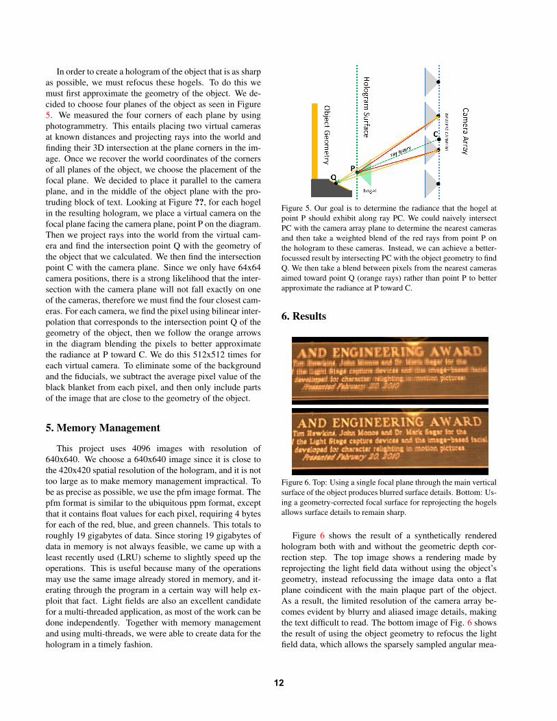
In order to create a hologram of the object that is as sharpas possible, we must refocus these hogels. To do this wemust first approximate the geometry of the object. We de-cided to choose four planes of the object as seen in Figure5. We measured the four corners of each plane by usingphotogrammetry. This entails placing two virtual camerasat known distances and projecting rays into the world andfinding their 3D intersection at the plane corners in the im-age. Once we recover the world coordinates of the cornersof all planes of the object, we choose the placement of thefocal plane. We decided to place it parallel to the cameraplane, and in the middle of the object plane with the pro-truding block of text. Looking at Figure ??, for each hogelin the resulting hologram, we place a virtual camera on thefocal plane facing the camera plane, point P on the diagram.Then we project rays into the world from the virtual cam-era and find the intersection point Q with the geometry ofthe object that we calculated. We then find the intersectionpoint C with the camera plane. Since we only have 64x64camera positions, there is a strong likelihood that the inter-section with the camera plane will not fall exactly on oneof the cameras, therefore we must find the four closest cam-eras. For each camera, we find the pixel using bilinear inter-polation that corresponds to the intersection point Q of thegeometry of the object, then we follow the orange arrowsin the diagram blending the pixels to better approximatethe radiance at P toward C. We do this 512x512 times foreach virtual camera. To eliminate some of the backgroundand the fiducials, we subtract the average pixel value of theblack blanket from each pixel, and then only include partsof the image that are close to the geometry of the object.
5. Memory Management
This project uses 4096 images with resolution of640x640. We choose a 640x640 image since it is close tothe 420x420 spatial resolution of the hologram, and it is nottoo large as to make memory management impractical. Tobe as precise as possible, we use the pfm image format. Thepfm format is similar to the ubiquitous ppm format, exceptthat it contains float values for each pixel, requiring 4 bytesfor each of the red, blue, and green channels. This totals toroughly 19 gigabytes of data. Since storing 19 gigabytes ofdata in memory is not always feasible, we came up with aleast recently used (LRU) scheme to slightly speed up theoperations. This is useful because many of the operationsmay use the same image already stored in memory, and it-erating through the program in a certain way will help ex-ploit that fact. Light fields are also an excellent candidatefor a multi-threaded application, as most of the work can bedone independently. Together with memory managementand using multi-threads, we were able to create data for thehologram in a timely fashion.
Figure 5. Our goal is to determine the radiance that the hogel atpoint P should exhibit along ray PC. We could naively intersectPC with the camera array plane to determine the nearest camerasand then take a weighted blend of the red rays from point P onthe hologram to these cameras. Instead, we can achieve a better-focussed result by intersecting PC with the object geometry to findQ. We then take a blend between pixels from the nearest camerasaimed toward point Q (orange rays) rather than point P to betterapproximate the radiance at P toward C.
6. Results
Figure 6. Top: Using a single focal plane through the main verticalsurface of the object produces blurred surface details. Bottom: Us-ing a geometry-corrected focal surface for reprojecting the hogelsallows surface details to remain sharp.
Figure 6 shows the result of a synthetically renderedhologram both with and without the geometric depth cor-rection step. The top image shows a rendering made byreprojecting the light field data without using the object’sgeometry, instead refocussing the image data onto a flatplane coindicent with the main plaque part of the object.As a result, the limited resolution of the camera array be-comes evident by blurry and aliased image details, makingthe text difficult to read. The bottom image of Fig. 6 showsthe result of using the object geometry to refocus the lightfield data, which allows the sparsely sampled angular mea-
12
surements to line up with each other and produce sharp textacross the entire surface of the steeply sloped plane.
We finally used the holographic printing process of [4]to produce real printed holographic stereograms of the ob-ject using geometry correction. First, we created 420× 420hogels with 256 × 256 angular resolution, with the mainvertical plaque of the object coincident with the hologramsurface. In the printed 30 cm × 30 cm result, the protrudingtext was mostly legible, but there was some blurring due tothe limited hogel resolution. We then generated a secondhogel dataset of 420 × 420 hogels with 512 × 512 angularresolution, and we moved the hologram surface to be coinci-dent with the front of the protruding base of the object. Twophotographs of this hologram (illuminated from the properillumination direction) can be seen in Figure 7. The smalltext on the sloped plane of the base is sharp and legible,which would not have been possible without the geometry-correction reprojection step. The main vertical plaque islegible with its larger text, but still slightly blurry. This isbecause even with the higher hogel resolution, the back-ground was still too far behind the plane of the hologramfor the holography process to produce a sharp result with afinite-sized light source. We will thus be printing one addi-tional hologram with the plane of the hologram through themiddle of the object, which we expect to be entirely sharpfor all surfaces.
7. Conclusion and Future WorkIn this work, we have shown a practical way of recording
and processing light field data used to create a high-qualityholographic print showing arbitrary illumination conditionsin the scene. By using geometry correction, we can refocusa light field acquired from far fewer viewpoints than the an-gular resolution of the hogels would appear to require. Theresulting hologram has sufficient image detail to observehigh-resolution details of an oject at a variety of depths.
AcknowledgementsThis work was sponsored by the University of South-
ern California Office of the Provost and the USC Provost’sPh.D. Fellowship. The content of the information does notnecessarily reflect the position or the policy of the US Gov-ernment, and no official endorsement should be inferred.
References[1] P. E. Debevec, C. J. Taylor, and J. Malik. Modeling and ren-
dering architecture from photographs: a hybrid geometry- andimage-based approach. In Proceedings of the 23rd annualconference on Computer graphics and interactive techniques,SIGGRAPH ’96, pages 11–20, New York, NY, USA, 1996.ACM. 1
[2] S. J. Gortler, R. Grzeszczuk, R. Szeliski, and M. F. Cohen.The lumigraph. In Proceedings of SIGGRAPH 96, Computer
Figure 7. The hologram.
Graphics Proceedings, Annual Conference Series, pages 43–54, Aug. 1996. 1
[3] M. Klug. Scalable digital holographic displays. In Proc. PICS2001: Image Processing, Image Quality, Image Capture Sys-tems Conference, April 2001. 2
[4] M. A. Klug, M. Holzbach, and A. Ferdman. US Patent6,330,088: Method and apparatus for recording one-step, full-color, full-parallax, holographic stereograms, Dec 2001. 2, 5
[5] M. Levoy and P. M. Hanrahan. Light field rendering. In Pro-ceedings of ACM SIGGRAPH 96, Computer Graphics Pro-ceedings, Annual Conference Series, pages 31–42, 1996. 1,3
[6] R. Ng. Fourier slice photography. ACM Trans. Graph.,24(3):735–744, July 2005. 1
[7] R. V. Pole. 3-d imagery and holograms of objects illuminatedin white light. Applied Physics Letters, 10(3):20–22, 1967. 1
[8] Z. Zhang. A flexible new technique for camera calibration.IEEE Trans. Pattern Anal. Mach. Intell., 22(11):1330–1334,Nov. 2000. 2


![The Iray Light Transport Simulation and Rendering System...Iray light transport simulation and rendering system [Iray] allows for rendering complex scenes by the push of a button and](https://static.documents.pub/doc/80x56/60f9158832e4cf1d3a2b60af/the-iray-light-transport-simulation-and-rendering-system-iray-light-transport.jpg)


