Geometry of Miura-folded metamaterials Mark Schenk and Simon D. Guest 1 Department of Engineering, University of Cambridge, Cambridge CB2 1PZ, United Kingdom Edited by T. C. Lubensky, University of Pennsylvania, Philadelphia, PA, and approved January 17, 2013 (received for review October 17, 2012) This paper describes two folded metamaterials based on the Miura-ori fold pattern. The structural mechanics of these meta- materials are dominated by the kinematics of the folding, which only depends on the geometry and therefore is scale-independent. First, a folded shell structure is introduced, where the fold pattern provides a negative Poisson’s ratio for in-plane deformations and a positive Poisson’s ratio for out-of-plane bending. Second, a cellu- lar metamaterial is described based on a stacking of individual folded layers, where the folding kinematics are compatible be- tween layers. Additional freedom in the design of the metamate- rial can be achieved by varying the fold pattern within each layer. I n this paper, we describe the use of origami for mechanical metamaterials, where the fold patterns introduce kinematic deformation modes that dominate the overall structural re- sponse. The geometry and kinematics of two types of folded metamaterial are described: a folded shell structure and a folded cellular metamaterial. The examples presented here are both based on a particular fold geometry: the classic Miura-ori pat- tern. This pattern has previously been considered for applica- tions, such as deployable solar panels (1), and was observed in the biaxial compression of stiff thin membranes on a soft elastic substrate (2, 3). In recent years, origami has seen a surge in research interest from engineers and physicists. Developments include folded sandwich panel cores (4, 5), origami-inspired stents (6), self- folding membranes (7), and cellular materials made from folded cylinders (8). An important concept is rigid origami, where the fold pattern is modeled as rigid panels connected through fric- tionless hinges. These assumptions make the study of origami folding a matter of kinematics. Of particular interest here are fold patterns where four fold lines meet at each vertex (so-called degree-4 vertices). Each such vertex has one degree of freedom, a tessellated fold pattern is overconstrained, and folding is only possible under strict geometric conditions. In a landmark paper, Huffman (9) studied rigid folding using spherical geometry; re- cent work includes the modeling of crease patterns using qua- ternions (10) and an increased understanding of the foldability conditions for partly folded quadrilateral surfaces (11, 12). In describing the properties of the folded metamaterials, we are here primarily concerned with the deformation kinematics. If required, these models can straightforwardly be extended to in- clude simple constitutive behavior at the fold lines [for instance, elastic (13) or plastic (14) behavior]. The paper is structured as follows. First, the Miura-ori unit cell is introduced, because its geometry plays a key role in the me- chanical properties of the folded metamaterials. The first such metamaterial is based on a single planar Miura-ori sheet: a fol- ded shell structure. Of particular interest are the shell’s out- of-plane kinematics. Second, a bulk metamaterial is proposed based on the stacking of individual Miura-ori layers, and its folding kinematics are explored. A brief discussion concludes the paper. Unit Cell Geometry A Miura unit cell is shown in Fig. 1. Its geometry can be pa- rameterized in a number of ways. We here define the unit cell by the dimensions of its smallest constituent component, a parallelogram with sides a and b and acute angle γ, and the dihedral fold angle θ ∈ [0, π/2] between the facets and the xy plane. The outer dimensions are then given by H = a · sin θ sin γ; [1] S = b · cos θ tan γ ffiffiffiffiffiffiffiffiffiffiffiffiffiffiffiffiffiffiffiffiffiffiffiffiffiffiffiffiffiffi 1 + cos 2 θ tan 2 γ p ; [2] L = a · ffiffiffiffiffiffiffiffiffiffiffiffiffiffiffiffiffiffiffiffiffiffiffiffiffiffiffiffiffi 1 − sin 2 θ sin 2 γ q ; [3] and V = b · 1 ffiffiffiffiffiffiffiffiffiffiffiffiffiffiffiffiffiffiffiffiffiffiffiffiffiffiffiffiffiffi 1 + cos 2 θ tan 2 γ p : [4] When designing metamaterials, the mechanical properties are often characterized in a partly folded state. For a selected set of outer dimensions H, S, V, L, the fold pattern parameters can then be back-calculated (4, 15). Additional useful rela- tionships are tan ξ = cos θ tan γ; [5] sin ψ = sin θ sin γ; [6] cos γ = cos ξ cos ψ ; [7] and sin φ = sin ξ=sin γ; [8] with ξ ∈ [0, γ], ψ ∈ [0, γ], and φ ∈ [0, π/2]. Note that a Miura-ori sheet can be folded from a flat sheet with only bending along the fold lines and, therefore, is a developable surface. Folded Shell Structures The first metamaterial here described is a folded shell structure. A partly folded Miura-ori sheet is considered as a shell struc- ture, where the local fold pattern alters the shell’s global me- chanical properties. It is an example of a compliant shell mechanism (16), where the overall kinematics are a function of the articulation along the fold lines as well as the deformation of the interlaying thin-walled facets. This hierarchical interaction of deformation kinematics can produce unexpected and fasci- nating mechanical properties. In describing the kinematics of a Miura-ori sheet, a distinction must be made between the in-plane and out-of-plane deforma- tions of the shell structure. Author contributions: M.S. and S.D.G. designed research, performed research, and wrote the paper. The authors declare no conflict of interest. This article is a PNAS Direct Submission. 1 To whom correspondence should be addressed. E-mail: [email protected]. This article contains supporting information online at www.pnas.org/lookup/suppl/doi:10. 1073/pnas.1217998110/-/DCSupplemental. 3276–3281 | PNAS | February 26, 2013 | vol. 110 | no. 9 www.pnas.org/cgi/doi/10.1073/pnas.1217998110
Transcript
Geometry of Miura-folded metamaterialsMark Schenk and Simon D. Guest1
Department of Engineering, University of Cambridge, Cambridge CB2 1PZ, United Kingdom
Edited by T. C. Lubensky, University of Pennsylvania, Philadelphia, PA, and approved January 17, 2013 (received for review October 17, 2012)
This paper describes two folded metamaterials based on theMiura-ori fold pattern. The structural mechanics of these meta-materials are dominated by the kinematics of the folding, whichonly depends on the geometry and therefore is scale-independent.First, a folded shell structure is introduced, where the fold patternprovides a negative Poisson’s ratio for in-plane deformations anda positive Poisson’s ratio for out-of-plane bending. Second, a cellu-lar metamaterial is described based on a stacking of individualfolded layers, where the folding kinematics are compatible be-tween layers. Additional freedom in the design of the metamate-rial can be achieved by varying the fold pattern within each layer.
In this paper, we describe the use of origami for mechanicalmetamaterials, where the fold patterns introduce kinematic
deformation modes that dominate the overall structural re-sponse. The geometry and kinematics of two types of foldedmetamaterial are described: a folded shell structure and a foldedcellular metamaterial. The examples presented here are bothbased on a particular fold geometry: the classic Miura-ori pat-tern. This pattern has previously been considered for applica-tions, such as deployable solar panels (1), and was observed inthe biaxial compression of stiff thin membranes on a soft elasticsubstrate (2, 3).In recent years, origami has seen a surge in research interest
from engineers and physicists. Developments include foldedsandwich panel cores (4, 5), origami-inspired stents (6), self-folding membranes (7), and cellular materials made from foldedcylinders (8). An important concept is rigid origami, where thefold pattern is modeled as rigid panels connected through fric-tionless hinges. These assumptions make the study of origamifolding a matter of kinematics. Of particular interest here arefold patterns where four fold lines meet at each vertex (so-calleddegree-4 vertices). Each such vertex has one degree of freedom,a tessellated fold pattern is overconstrained, and folding is onlypossible under strict geometric conditions. In a landmark paper,Huffman (9) studied rigid folding using spherical geometry; re-cent work includes the modeling of crease patterns using qua-ternions (10) and an increased understanding of the foldabilityconditions for partly folded quadrilateral surfaces (11, 12).In describing the properties of the folded metamaterials, we
are here primarily concerned with the deformation kinematics. Ifrequired, these models can straightforwardly be extended to in-clude simple constitutive behavior at the fold lines [for instance,elastic (13) or plastic (14) behavior].The paper is structured as follows. First, the Miura-ori unit cell
is introduced, because its geometry plays a key role in the me-chanical properties of the folded metamaterials. The first suchmetamaterial is based on a single planar Miura-ori sheet: a fol-ded shell structure. Of particular interest are the shell’s out-of-plane kinematics. Second, a bulk metamaterial is proposedbased on the stacking of individual Miura-ori layers, and itsfolding kinematics are explored. A brief discussion concludesthe paper.
Unit Cell GeometryA Miura unit cell is shown in Fig. 1. Its geometry can be pa-rameterized in a number of ways. We here define the unit cellby the dimensions of its smallest constituent component, aparallelogram with sides a and b and acute angle γ, and the
dihedral fold angle θ ∈ [0, π/2] between the facets and the xyplane. The outer dimensions are then given by
H = a · sin θ sin γ; [1]
S= b ·cos θ tan γffiffiffiffiffiffiffiffiffiffiffiffiffiffiffiffiffiffiffiffiffiffiffiffiffiffiffiffiffiffiffi1+ cos2θ tan2γ
p ; [2]
L= a ·ffiffiffiffiffiffiffiffiffiffiffiffiffiffiffiffiffiffiffiffiffiffiffiffiffiffiffiffiffi1− sin2θ sin2γ
q; [3]
and
V = b ·1ffiffiffiffiffiffiffiffiffiffiffiffiffiffiffiffiffiffiffiffiffiffiffiffiffiffiffiffiffiffiffi
1+ cos2θ tan2γp : [4]
When designing metamaterials, the mechanical properties areoften characterized in a partly folded state. For a selected setof outer dimensions H, S, V, L, the fold pattern parameterscan then be back-calculated (4, 15). Additional useful rela-tionships are
tan ξ= cos θ tan γ; [5]
sinψ = sin θ sin γ; [6]
cos γ = cos ξ cosψ ; [7]
and
sinφ= sin ξ=sin γ; [8]
with ξ ∈ [0, γ], ψ ∈ [0, γ], and φ ∈ [0, π/2]. Note that a Miura-orisheet can be folded from a flat sheet with only bending along thefold lines and, therefore, is a developable surface.
Folded Shell StructuresThe first metamaterial here described is a folded shell structure.A partly folded Miura-ori sheet is considered as a shell struc-ture, where the local fold pattern alters the shell’s global me-chanical properties. It is an example of a compliant shellmechanism (16), where the overall kinematics are a function ofthe articulation along the fold lines as well as the deformation ofthe interlaying thin-walled facets. This hierarchical interactionof deformation kinematics can produce unexpected and fasci-nating mechanical properties.In describing the kinematics of a Miura-ori sheet, a distinction
must be made between the in-plane and out-of-plane deforma-tions of the shell structure.
Author contributions: M.S. and S.D.G. designed research, performed research, and wrotethe paper.
The authors declare no conflict of interest.
This article is a PNAS Direct Submission.1To whom correspondence should be addressed. E-mail: [email protected].
This article contains supporting information online at www.pnas.org/lookup/suppl/doi:10.1073/pnas.1217998110/-/DCSupplemental.
In-Plane Kinematics.When modeled as rigid origami, the Miura-orisheet has a single in-plane expansion mode, with kinematics thatcan be characterized by an expansion coefficient or Poisson’s ratio:
νSL = −«L«S
= −SLdLdS
= − tan2ξ; [9]
where the strains «L and «S are instantaneous true strains. Asillustrated in Fig. 2, the Poisson’s ratio is always negative; thisunusual material property can be found in microstructured mate-rials referred to as auxetics (17) as well as fluctuating membranesand crumpled papers (18). The negative in-plane Poisson’s ratioof the Miura-ori sheet is well-known (1, 3). However, previousformulations obscured an important insight: the Poisson’s ratio isonly a function of the angle ξ in the xy plane or, equivalently, theratio S/V. This insight will lead on to the folded cellular meta-material described in the next section.
Out-of-Plane Kinematics.Of particular interest are the out-of-planekinematics of the Miura-ori folded shell structure (Fig. 3). Simpleexperiments revealed two out-of-plane deformation modes:saddle and twisting modes (15). A saddle-shaped bending mode isconventionally expected in a material with a positive Poisson’sratio. For the Miura-ori sheet, therefore, the Poisson’s ratios forin-plane and out-of-plane deformations are of opposite sign.
A key observation is that, for out-of-plane deformations, thefacets of the Miura unit cell must bend. These modes can, there-fore, not be captured in a rigid origami model without introducingadditional fold lines. For themechanical analysis, the facet bendingis modeled by introducing a diagonal fold line to the parallelo-gram facets. The additional fold lines can be considered as aconvenient construct to simplify modeling. However, such spon-taneous fold lines can, in fact, be observed in paper models, andindeed, mathematical models of origami folding show that de-velopable deformations of facets bounded by straight lines mustremain piecewise planar (19). Their formation is also motivatedby the physics of stress concentration in thin-walled shells (20, 21).To first-order approximation, the choice of diagonal for theadditional fold line does not matter (SI Appendix, section S1).We here select the shorter diagonal, motivated by observationof physical models as well as energetic considerations.Schenk and Guest (13) described a simple mechanical model to
study the dominant kinematics of the sheets, whereby the foldedsheet was modeled as a pin-jointed truss (SI Appendix, section S2).By introducing a bending stiffness along the fold lines, Kfold, andacross the facets, Kfacet, the modal response of the folded shell wasstudied. An important nondimensional material parameter is theratio of the fold and facet stiffness. The modal analysis confirmed
x
z
b
y
a
H
2S2L
V
Fig. 1. A folded Miura-ori sheet consists of tessellations of a unit cell. Theunit cell geometry can be described using parameters defining a parallelo-gram facet, a, b, γ, and fold angle θ ∈ [0, π/2]. An alternative parameteri-zation is given by dimensions H, S, V, L. Other useful angles are shown,where ξ and ψ are angles between fold lines and the y axis and θ and φ aredihedral angles between facets and the xy and yz planes, respectively. Threeconfigurations with θ = {0, π/4, π/2} are shown.
0 10 20 30 40 50 60 70 80 90−5
−4.5
−4
−3.5
−3
−2.5
−2
−1.5
−1
−0.5
0
θ [deg]
Poi
sson
’s ra
tio νSL
65˚70˚
75˚
γ = 60˚
55˚
50˚
45˚
Fig. 2. The in-plane expansion coefficient of a Miura-ori sheet, νSL = −cos2θtan2γ, for different geometries γ. The arrows indicate the primary straindirection δS; pictured are configurations with γ = 60° and a/b = 1.
Fig. 3. (A) The undeformed configuration and the (B) twisting and (C) saddle-shaped deformation modes of a Miura sheet with 9 × 9-unit cells (a/b = 1, γ = π/3). It isshown in ref. 13 that, over a wide range of geometries and material parameters, these deformation modes are the most flexible. Only for configurations where thebending stiffness of the facets is much greater than the bending stiffness of the fold lines is the planar mechanism (Fig. 1) the most flexible deformation mode.
Schenk and Guest PNAS | February 26, 2013 | vol. 110 | no. 9 | 3277
the bending and twisting modes as dominant deformation modesover a wide range of unit cell geometries and stiffness ratios.In previous studies, the coupling coefficient between the op-
posing curvatures in the saddle-shaped deformation mode wasnot quantified, because the Gaussian curvature varies across thedeformed sheet. The unit cell deformations must necessarily varyacross the surface, because the doubly curved geometry cannotbe attained through a tessellation of a single deformed unit cell.To first order, however, the doubly curved deformation of the
folded sheet can be described by considering a single unit cellwith tessellation boundary conditions (Fig. 4). The tessellationboundary conditions reduce the degrees of freedom of the unitcell. As detailed in SI Appendix, section S3, the remaining de-formation modes can then be separated into three orthogonalmodes: a planar mode, a symmetric out-of-plane mode (i.e.,saddle), and an antisymmetric out-of-plane mode (i.e., twisting).For the saddle mode, the out-of-plane coupling coefficient
between the curvatures, νκ = −κyy/κxx, is of interest. The first-orderdeformation modes provide the necessary information to nu-merically calculate the change in curvature. Remarkably, the out-of-plane coupling coefficient is found to be equal and opposite tothe in-plane Poisson’s ratio:
νκ = −κyyκxx
= − νSL: [10]
Within the assumed kinematics for the folded sheets (i.e., onlydevelopable deformations of the unit cell facets), the attainablegeometries are strictly limited. Although a large range of de-formed sheet configurations can be attained using combinationsof stretching, bending, and twisting, deformations such as in-planeand out-of-plane shear are not compatible with this kinematicmodel. Physical sheets must, therefore, undergo nondevelopabledeformations (i.e., in-plane strains of the facets) to attain thosemodes (5). Nonetheless, it is worth emphasizing that the initiallyplanar Miura folded shell can attain doubly curved configurationsand thus, changes its global Gaussian curvature, with only devel-opable deformations of the unit cell facets.Another folded shell structure, the eggbox sheet, was studied
in the work in ref. 13. It is shown to exhibit a material behaviorexactly opposite to the behavior described here for the Miura-ori: it has a positive in-plane Poisson’s ratio but a negativePoisson’s ratio in certain out-of-plane deformation modes. Adifferentiating feature is that the eggbox sheet is nondevelopableand therefore, cannot be folded from a flat sheet.
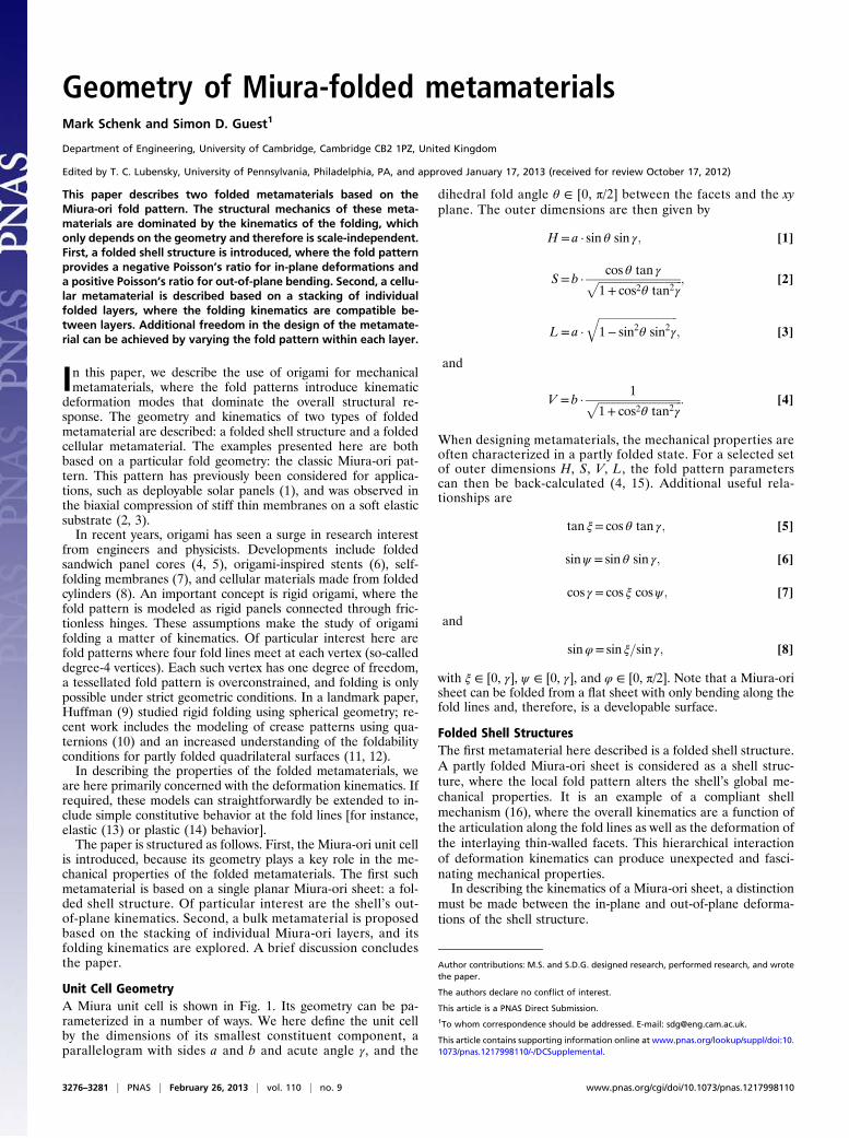
Folded Cellular MetamaterialWe can build on the results of the in-plane kinematics describedpreviously to show that different Miura sheets can be stacked toform a 3D foldable metamaterial. Eq. 9 shows that the couplingbetween expansion in the x and y directions shown in Fig. 1 dependsonly on the in-plane angle ξ. In particular, it does not depend onheight H. Hence, Miura sheets with different heights H can bestacked together, bonded along fold lines, and still fold freely (Fig.5). The result of the stacking is a cellular metamaterial that expands/contracts omnidirectionally and is highly anisotropic. Examples offolded models are shown in SI Appendix, section S4.
Stacked Geometry. In the stacked configuration, the fold patternmay vary from layer to layer, but it is here assumed that the unitcell geometry alternates between successive layers: ABABA etc.The unit cells in successive layers A and B must share at leastthree geometric parameters, leaving a single free parameter.This constraint can be recognized when considering the extrinsicunit cell geometry: SA = SB, VA = VB, and LA = LB, where theunit cell heights HA and HB can be selected independently. Thispaper assumes, without loss of generality, that HB ≥ HA. In termsof the intrinsic geometric parameters, if γB ≥ γA is taken as theindependent variable for layer B, the corresponding unit cellparameters can be calculated by
aB = aAcos γAcos γB
; [11]
bB = bA; [12]
A
B C
D,i
D,ii D,iiiFig. 4. To capture out-of-plane deformations, (A) additional fold lines(bd, bf, eg, and ei ) are introduced diagonally across the facets. (B) Thedeformations of the unit cells can be visualized by means of boundingplanes, which represent the tessellation boundary conditions ∠adg = ∠cfiand ∠abc = ∠ghi. The resulting out-of-plane deformation modes are(C ) twisting and (D) saddle-shaped bending, which are, respectively, an-tisymmetric and symmetric in the yz plane (15). (D, i ) For the bendingmode, the tilt angles of the bounding planes, dρxx and dρyy, can be con-verted to a corresponding change in curvature of the folded sheets: (D, ii )κxx = dρxx/2S; (D, iii ) κyy = dρyy/2L. Additional details are in SI Appendix.
3278 | www.pnas.org/cgi/doi/10.1073/pnas.1217998110 Schenk and Guest
where Eq. 13 provides a transfer function between the foldangles of the successive layers A and B. In this paper, we onlyconsider θA ∈ [0, π/2]. Extending the range to include θA ∈ [−π/2,0] will result in a metamaterial where the layers are no longernested but connected along their ridges.
Expansion Coefficient. As a result of the stacking process, the in-plane expansion coefficient of both the cellular metamaterial anda single Miura sheet are identical. For the 3D metamaterial,the through-thickness expansion coefficient is now relevant. Fora single layer, the coefficients can be written as
νLH = −«H«L
=1− sin2ψsin2ψ
[14]
and
νSH = − νLHνSL; [15]
with νSL being the in-plane expansion coefficient from Eq. 9. Thesingle-layer expansion coefficient will, thus, always be positive,and its height will reduce as the sheet expands in plane.For a stacked metamaterial, the total stack height Hs = n(HB −
HA) + HA, with n the number of repeating layer pairs AB. Forlarge values of n, the through-thickness expansion coefficientcan be written as
νLH = −cos γBcos γA
cosψA
tanψA
1sinψB
: [16]
Within the given bounds on fold angle θA, νLH will always benegative. In other words, the expansion coefficient for the 3D
metamaterial, consisting of a layering of Miura sheets, is oppo-site to that of its constituent layers.For small numbers of n, the expansion coefficient of the
metamaterial will transition from a positive to negative Poisson’sratio behavior, respectively governed by Eqs. 14 and 16, as thenumber of stacked layers increases.
Relative Density. An important property of a cellular material is itsrelative density. For a single-layered Miura-sheet, this quantity isgiven by
ρ= t ·ab sin γHSL
; [17]
with t is the sheet thickness. The density is minimal when thedenominator (i.e., the outer volume of the unit cell) reachesits maximum:
∂HSL∂θ
= 4a2btan2γcos γ
�1− 2 sin2θ
�cos3ψ
1+ tan2ξ= 0; [18]
which will always be satisfied at θ = π/4. In other words, regard-less of its geometry, a single-folded Miura-ori layer will alwaysreach maximal volume at the same fold angle. A similar expres-sion for the stacked configuration is less obviously derived, be-cause the height HB of the stacking layer can be freely specified.We here state the material density as a function of the partlyfolded configuration,
expressed in terms of the dimensionless groups ρc/ρ, t/L, HB/HA,L/HA, and V/S.
ABABABA
Fig. 5. Individual Miura-ori sheets can be stacked together and bonded along joining fold lines to form a folded cellular metamaterial. Although the Miura-ori unit cell geometry varies between successive layers, the stacked configuration preserves the folding kinematics, and the 3D metamaterial expands/con-tracts uniformly. Here, a stack with alternating layers ABABABA is shown. An animation of the folding motion is provided by Movie S1.
Schenk and Guest PNAS | February 26, 2013 | vol. 110 | no. 9 | 3279
Self-Locking. An interesting feature of the Miura-ori patternis the ability to automatically control the maximum fold depthof a sheet, which can be achieved by varying the unit cell ge-ometry within a layer: when a unit cell reaches its maximumfold angle θ = π/2, it locks up, and the folding motion of the
entire sheet is halted. It will be shown that, in the stackedconfiguration, the folding motion is preserved when varyingthe unit cell geometry within the layers, and the metamaterialcan, therefore, be designed to lock in a predetermined con-figuration (Fig. 6).First consider two adjoining unit cells A1 and A2 with different
geometries (Fig. 7). Taking A1 as reference configuration, therelationships ψA1 = ψA2 and aA1 = aA2, thus, leave γA2 and bA2 tobe chosen freely for unit cell A2. By selecting γA2 < γA1, unit cellA2 will lock at θA2 = π/2, when ψA = γA2. The corresponding θA1can be calculated from
θA1 = arcsin�sin θA2
sin γA2sin γA1
�: [20]
Next, consider the stacking of layers A and B, with unit cells B1and B2 stacked onto A1 and A2, respectively (Fig. 7). Using Eq.11, with the knowledge that aA1 = aA2 and aB1 = aB2, the geo-metric condition
cos γA1cos γB1
=cos γA2cos γB2
[21]
must be satisfied to enable stacking. With the four unit cells inplace, their combined kinematics can be studied. The in-plane
Fig. 6. A self-locking folded cellular metamaterial. As the Miura sheetscontract, the unit cells in the central column reach their maximum fold anglebefore the rest of the layer, thereby halting the folding motion and lockingthe metamaterial in a predetermined configuration. This behavior can beachieved by varying the unit cell geometry within each layer. An animationof the folding motion is provided by Movie S2.
A1
A2
B1
B2
A
B
Fig. 7. The unit cell geometry of the Miura pattern can be varied within each layer. A shows layer A with unit cells A1 and A2, on which are stacked unit cellsB1 and B2 in layer B. The relationship between the unit cell geometries is given by Eq. 21. The geometry γA2 < γA1 is selected such that unit cells A2 and B2 willlock in a predetermined configuration, which is shown in B.
3280 | www.pnas.org/cgi/doi/10.1073/pnas.1217998110 Schenk and Guest
expansion coefficient of unit cell A2, as transferred from A1 toA2, is given by
−νA2SL = tan2γA2 −sin2γA1cos2γA2
sin2θA1: [22]
Similarly for unit cell B2, as transferred through A1 and B1, theexpansion coefficient can be expressed as
−νB2SL =cos2γB1 cos2θA1 tan2γA1
cos2γB2
−sin2γB1cos2γB2
+ tan2γB2:
[23]
To preserve the compatibility between layers A and B duringfolding, Eqs. 22 and 23 must be equal for any value of θA1. Itcan be shown that this equality is satisfied under the same geo-metric condition as given in Eq. 21. In other words, when a config-uration is found where four unit cells fit together, they will remaincompatible in any folded configuration. Therefore, a stackedmetamaterial where the unit cell geometry is varied within thelayers will still fold freely.
DiscussionIn this paper, we have described the geometry of two foldedmetamaterials, both based on the Miura-ori fold pattern, thatdisplay intriguing mechanical properties.The folded shell structure, consisting of a single Miura sheet,
has opposite Poisson’s ratios for in-plane and out-of-planedeformations. For planar deformations, it has a negative Poisson’sratio, whereas under bending, it deforms into a saddle-shaped
configuration characteristic of a positive Poisson’s ratio. Remark-ably, these Poisson’s ratios are found to be equal and opposite.By stacking folded Miura layers into a 3D structure, a cellular
folded metamaterial is obtained. Although the unit cell geometryvaries between successive layers, the folding motion is preservedfor the stack. The result is a metamaterial that can fold andunfold uniformly. What is more, because the folding motion hasa single degree of freedom, the folded metamaterial can bemachined into any desired shape and still preserve its foldingmotion. Applications can be found in impact absorption as wellas deployable structures. A key difference with the foldingmetamaterial described in ref. 8 is the potential simplicity ofmanufacture. The individual folded sheets can be manufacturedusing established manufacturing methods (14) before beingstacked and joined along fold lines.The geometric richness of the stacked metamaterial can be
further exploited by varying the fold pattern within a layer. Forinstance, the folding motion can be halted at a desired fold angle,enabling the design of metamaterials that can lock into a specificconfiguration. This ability can be put to effective use in self-as-sembly techniques. Using established micromanufacturing tech-niques, a sheet can be folded using strain differentials across thefold lines; the final configuration can then be ensured by usinga self-locking geometry. Alternatively, the self-locking can pro-vide a tailored stiffening response of the metamaterial under animpact load.The geometric approach taken in this paper clearly provides
a highly idealized analysis of the structural mechanics of thefolded metamaterials. Future work may characterize the me-chanical properties that do not follow from the described kine-matics, such as shear deformations.
1. Miura K (1985) Method of packaging and deployment of large membranes in space.
Inst Space Astronaut Sci Rep 618:1–9.2. Tanizawa K, Miura K (1978) Large displacement configurations of bi-axially com-
pressed infinite plate. Trans Jpn Soc Aeronaut Space Sci 20(50):177–187.3. Mahadevan L, Rica S (2005) Self-organized origami. Science 307(5716):1740.4. Klett Y, Drechsler K (2011) Designing technical tessellations. Origami 5: Fifth In-
ternational Meeting of Origami Science, Mathematics, and Education (5OSME), eds
Wang-Iverson P, Lang RJ, Yim M (CRC, Boca Raton, FL) pp 305–322.5. Lebée A, Sab K (2010) Transverse shear stiffness of a chevron folded core used in
sandwich construction. Int J Solids Struct 47(18–19):2620–2629.6. Kuribayashi K, et al. (2006) Self-deployable origami stent grafts as a biomedical ap-
plication of Ni-rich TiNi shape memory alloy foil. Mater Sci Eng A Struct Mater 419(1–
2):131–137.7. Pickett GT (2007) Self-folding origami membranes. Europhys Lett 78(4):48003.8. Tachi T, Miura K (2011) Cellular origami structure from foldable tubes. Proceedings
of the 7th International Structural Morphology Group Seminar, London, United
Kingdom, September 17–18, 2011.9. Huffman DA (1976) Curvatures and creases: A primer on paper. IEEE Trans Comput
C-25(10):1010–1019.10. Wu W, You Z (2010) Modelling rigid origami with quaternions and dual quaternions.
Proc R Soc Lond A Math Phys Sci 466(2119):2155–2174.11. Tachi T (2009) Generalization of rigid foldable quadrilateral mesh origami. J Int Assoc
Shell Spatial Struct 50(3):173–179.
12. Stachel H (2010) A kinematic approach to Kokotsakis meshes. Comput Aided GeomDes 27(6):428–437.
13. Schenk M, Guest SD (2011) Origami folding: A structural engineering approach.Origami 5: Fifth International Meeting of Origami Science, Mathematics, and Edu-cation (5OSME), eds Wang-Iverson P, Lang RJ, Yim M (CRC, Boca Raton, FL) pp291–303.
14. Schenk M, Allwood JM, Guest SD (2011) Cold gas-pressure folding of Miura-orisheets. Steel Research International, Special Issue Proceedings of the InternationalConference on Technology of Plasticity (ICTP) 2011, pp 459–464. Available at www.materialsviews.com/the-10th-international-conference-on-technology-of-plasticity-ictp-2011/.
15. Schenk M (2011) Folded shell structures. PhD thesis (Univ of Cambridge, Cambridge,United Kingdom).
16. Seffen KA (2012) Compliant shell mechanisms. Philos Trans R Soc Lond A 370(1965):2010–2026.
17. Lakes R (1987) Foam structures with a negative Poisson’s ratio. Science 235(4792):1038–1040.
18. Nelson DR (2002) Defects and Geometry in Condensed Matter Physics (CambridgeUniv Press, Cambridge, United Kingdom).
19. Demaine ED, Demaine ML, Hart V, Price GN, Tachi T (2009) (Non)existence of pleatedfolds: How paper folds between creases. Graphs and Combinatorics 27(3):377–397.
20. Witten TA (2007) Stress focusing in elastic sheets. Rev Mod Phys 79(2):643–675.21. Korte AP, Starostin EL, van der Heijden GHM (2011) Triangular buckling patterns of
twisted inextensible strips. Proc R Soc Lond A Math Phys Sci 467(2125):285–303.
Schenk and Guest PNAS | February 26, 2013 | vol. 110 | no. 9 | 3281