NASA TECHNICAL MEMORANDUM NASA_vl-78276 _ (_&SA-TM-78276) EVALUATION OF THE ST_ES5 _80-25W13 ' COP'_OSIO_ C-_CKIHG RESISTANCE OF SEVERAL _IGh STEEMG_ LOW ALLOY STEELS (NASA) 28 p HC ._/RF A01 CSCL 11F l_nclas . G 3/26 22417 EVALUATION OFl_lESTRESS CORROSION CRACKING RESISTANCE OF SEVERAL HIGH STRENGTH LOW ALLOYSEELS J By T. S. Humphries and E. E. Nelson Materialsand Processes Laboratory May 1980 NASA • GeorgeC. Marshall Space Flight Center - Marshall SpaceFlight Center,Alabama Ire - Foe "s _|gO (RevJImo 1971) https://ntrs.nasa.gov/search.jsp?R=19800016917 2018-09-01T12:22:13+00:00Z
Transcript
NASA TECHNICAL
MEMORANDUM
NASA_vl-78276 _:(_&SA-TM-78276) EVALUATION OF THE ST_ES5 _80-25W13
' COP'_OSIO_ C-_CKIHG RESISTANCE OF SEVERAL_IGh STEEMG_ LOW ALLOY STEELS (NASA) 28 p
s. PERFORMINGORaANIZATIONNAMEAReAUORESS 10. WORXUNITNO.
George C. Marshall Space FUght Center 11. CONTRACTORGRANT"0.Marshall Space Flight Center, Alabama 35812
13. TYPE OF REPOR', & PERIOD CeVEREDi
. 12 S_0NSORI.a_;ENCYNAMEAN0AOOMSS
National Aeronautics and Space Administration Technical Memorandum. Washington, D.C. 20546 14. SPONSORINGAGENCYCOOE
i
is. SUPP'EMENT_YNOTES
Prepared by Materials and Processes Laboratory, Science and Engineering
t
11. ABSTRACT
A comprehensive investigation of the stress corrosion cracking resistance ofhigh strength alloy steels 4130, 4340, and H-11 at selected strength levels andD6AC and HY140 at a single strength is presented. Round tensile and C-ring typespecimens were stressed up to 100 percent of their yield strengths and exposed toalternate immersion in salt water, salt spray, the atmosphere at Marshall SpaceFlight Center, and the seacoast at Kennedy Space Center. Under the test conditions4130 and 4340 steels heat treated to a tensile strength of 1240 MPa (180 ksi), H-11and D6AC heat treated to a tensile strength of 1450 MPa (210 ksi), and HY140(1020 MPa, 148 ksi) are resistant to stress corrosion cracking because failures werenot encountered at stress levels up to 75 percent of their yield strengths. A maxi-mtL_ exposure period of one month for alternate immersion in salt water or saltspray and three months for seacoast is indicated for alloy steel to avoid falseindications of stress corrosion cracking because of failure resulting from severepitting.
|7. KE_' WORDS 18. DISTRIBUTION STA_'EMEN '1_
Unclassified -- Unlimited
19. SECURITY CL.ASSllr. (dtk/t .iP_atl 20. SECURITY CLASSllr. (of title pale ) 21, NO. OIr PAGES 22. PRICE
Unclassified Unclsssi fled 28 NTIS, t
MSr¢- Fore ! |11| (Itev Deeembe_ ! t I !) For Ule by Naflonel Technical Information .Yet'vice, _prtfl|fleld, Vlrglni| 221 $1
1. SEM fraetograp_s showing blocky type intergranularinitiation and propagation and a ductile area ofrapid failure of a 4340 steel speeimen after 5 daysat KSC ............................................... 18
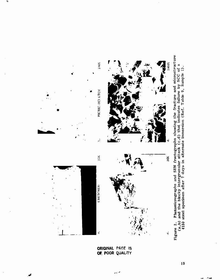
2. Photomicrographs and SEM fraetographs showingthe fracture and mierostrueture and the blockyintergranular attack that indicates failure by SCCof a 4130 steel specimen after 7 days in alternateimmersion ............................................. 19
3. SEM fraetographs showing blocky intergrmlularcorrosion indicative of SCC of a 4130 steel sped-men after 13 days in AI .............................. 20
4. Photomicrograph and SEM fractographs showing thesevere pitting and ductile type failure of a 4130steel specimen after 91 days at KSC .................. 21
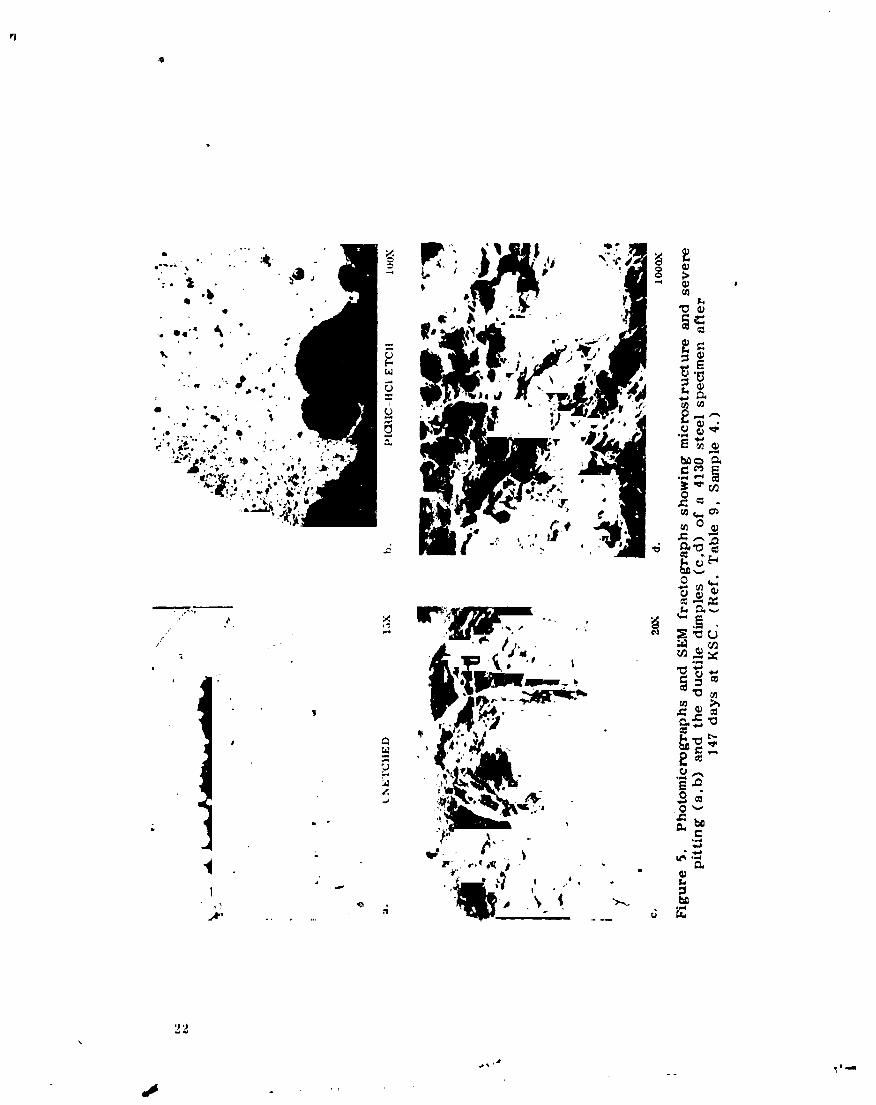
5. Photomicrographs and SEM fractographs shnwingmierostrueture and severe pitting and the ductiledimples of a 4130 steel specimen after 147 daysat KSC ............................................... 22
6. Photomicrograph and SEM fraetographs showing themierostrueture and ductile failure of a 4130 steel
specimen after 25 days in salt spray .................. 23
iv
.j, ._
,14
1980016917-004
LISTOFTABLES
Table Title Pnge
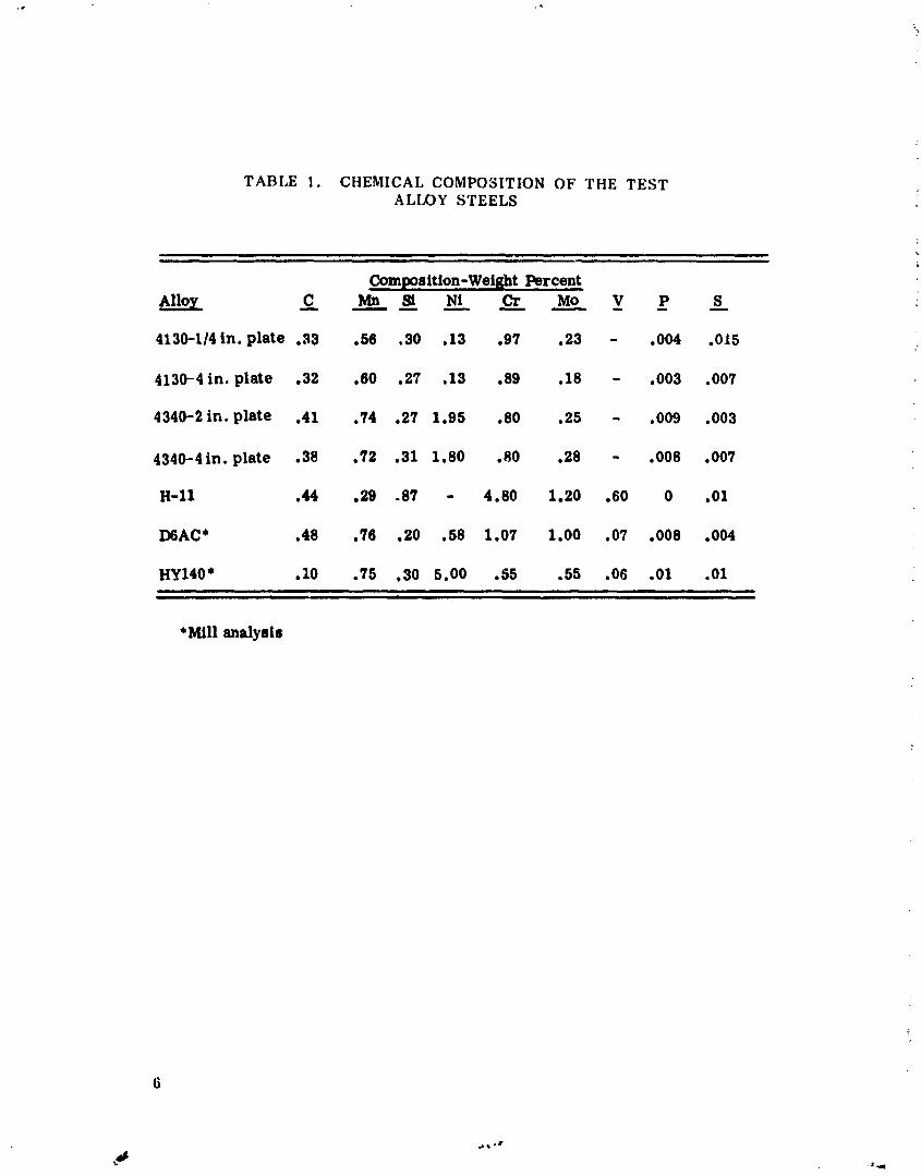
1. Chemical Composition of the Test Alloy Steels .......... 6r
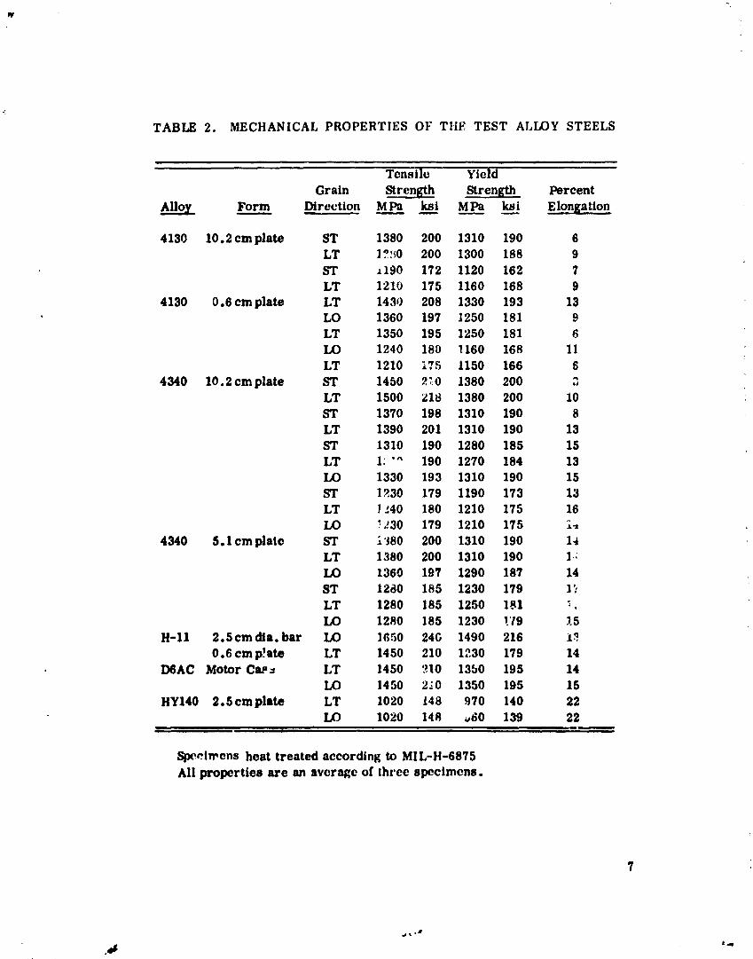
2. Mechanical Properties o__ the Test AHoy Steels .......... 7
3. SCC Test Results of 4130 Steel ........................ 8
4. SCC Test Results of 4340 Steels ........................ 9
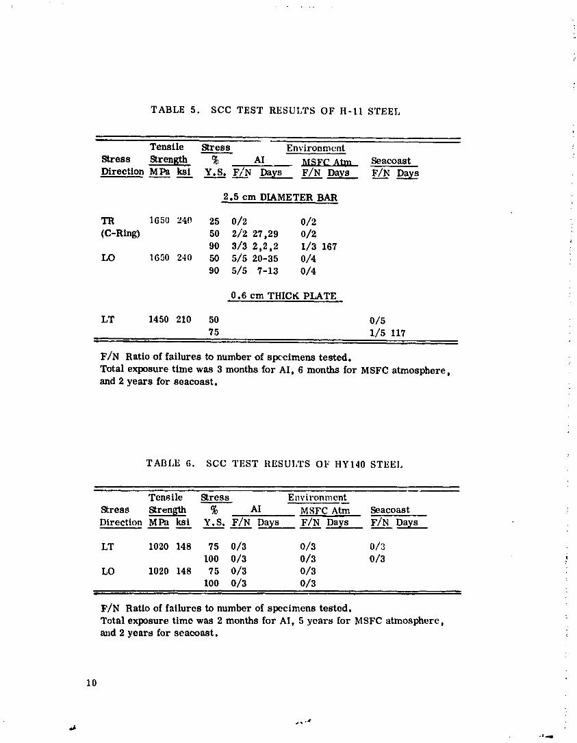
5. SCC Test Results of H-11 Steel ........................ 10
6. SCC Test Results of HY140 Steel ....................... 10
7. SCC Test Results of D6AC Steel ....................... 11
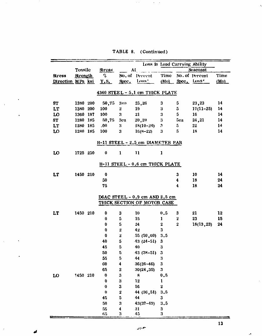
8. Loss in Load Carrying Ability of Alloy Steels ........... 12
9. Effect of Pitting and Exposure Time on Type ofFailure ................................................ 15
10. Comparison of SCC Test Results of Alloy SteelsBased on Two Exposure Periods ........................ 16
The requirement for continuing increases in the weight of spacepayloads makes it imperative that extreme measures be taken to reducenon-payload weight. This dictates that many structural components ofspace vehicles be fabricated from high strength steels to obtain highstrength-to-density ratios. The advent of the Space Shuttle hasincreased the problem of material selection for aerospace structuraldesigners. Not only have payloads increased significantly, but also theShuttle is a multi-mission vehicle as opposed to a single mission for pre-vious vehicles. This extension of service life certainly increases theneed for material reliability in structural applications. The contributionof stress corrosion cracking (SCC) to service failure of vehicle structuresand components is therefore of extreme interest.
This investigation was designed to evaluate the SCC of highstrength low alloy steels used or contemplated for use in space vehicles.Some of the high strength low alloy steels that are of interest to theaerospace designers are 4130, 4340, H-11, HY140, and D6AC, and these
!, are the materials evaluated. The testing was accomplished by exposingstressed specimens of the materials to corrosive environments that arerepresentative of, or more severe than, those encountered during themanufacturing, testing, and servicing of space vehicles.
EXPERIMENTAL PROCEDURE
Although not as pronounced as in aluminum alloys,the SCC resist-anee of alloy steels is affected by the grain orientation. For this reason,tests were conducted in at least two grain directions for all test condi-tions. Two laboratory exposure media, alternate immersion in 3.5 percentsodium chloride (hereafter called AI) and 5 percent salt spray, wereemployed in addition to two natural environments, outside exposure atMarshall Space Flight Center (MSFC) and seacoast exposure at KennedySpace Center (KSC). Round tensile specimens stressed in uniaxial tensionand C-rings stressed by constant deflection were used exclusively fortest specimens. The C-ring specimen was used only to test the trans-verse direction of a 1 in. diameter bar of H-I1 steel.
...t ...4"
1980016917-006
All specimens were fabricated and then heat treated according toMIL-H-6875 except for alloys H-11 and D6AC which were supplied in theheat treat condition tested. The specimens were strained or deflectedto the desired stresses (40 to 100 percent of the directional 0.2 percentoffset yield strengths) which were calcu]ated from measured mechanicalproperties. The stressing jigs that were exposed to salt water and saltspray were coated with a strippable coating (Mascoat No. 2, WesternCoating Company) to protect them from corrosion and to prevent galvanicaction between the aluminum jigs and steel specimens. Mascoat No. 2 isnot suitable for outside exposure because it cracks and flakes off. Foroutside exposure, several coats of neoprene rubber cement (MSFC X-94)were applied to the area where the specimen contacts the end caps tocombat galvanic corrosion. The specimens were wiped with alcohol andexposed to the selected test media. A detailed description of the testspecimens, formulas for calculating deflection and strain, and methods ofloading and testing are given in Reference 1.
RESULTS AND DISCUSSION
The compositions of the test alloys are listed in Table 1, and themechanical properties of the materials in all heat treatments and graindirections tested are given in Table 2. The SCC results in all testmedia are shewn in Tables 3 through 7. These results indicate that theSCC resistance of these alloy steels was affected by the grain directionin which the stress was applied. The short and long transverse direc-tions were the most susceptible and thus these directions should alwaysbe tested when evaluating alloy steels.
During the testing phase of this investigation, it was noted thatspecimens of all test materials suffered severe pitting in all media exceptMSFC atmosphere. The, effect of the pitting is shown in Table 8 wherethe losses in load carrying ability of the corroded specimens were calcu-lated from the differences in their breaking strengths (breaking loadsdivided by cross-sectional areas before exposure) and the tensile strengthsof the parent materials. There are several ways in which pitting ornon-uniform corrosion can interfere with the interpretation of SCC testresults. Pitting of tension specimens with relatively small cross sectionscan significantly reduce the effective cross-sectional areas and producea net section stress greater than the nominal gross section stress. Thiscan result in SCC of specimens at an actual stress higher than theintended nominal test stress or fracture by mechanical overload ofmaterials that are not susceptible to SCC. This is illustrated in Table 9and Figures 1 through 6 in which the effect of pitting and exposure timeon the type of failure is shown. One method of combatting the problemassociated with pitting is to shorten the exposure period as much aspossible and still maintain an adequate period for SCC evaluation ofmaterials. This is illustrated in Table 10 in which failures of all testalloys after one month exposure in A1 and salt sprayL and three months
J._w4
1980016917-007
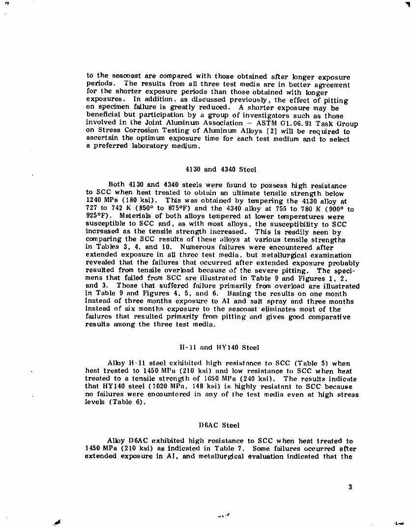
to the seacoast are compared with those obtained after longer exposureperiods. The results from all three test media are in better agreementfor the shorter exposure periods than those obtained with longerexposures. In addition, as discussed previously, the effect of pittingon specimen failure is greatly reduced. A shorter exposure may bebeneficial but participation by a group of investigators such as thoseinvolved in the Joint Aluminum Association - ASTM G1.06.91 Task Groupon Stress Corrosion Testing of Aluminum Alloys [2] will be required toascertain the optimum exposure time for each test medium and to selecta preferred laboratory medium.
4130 and 4340 Steel
Both 4130 and 4340 steels were found to possess high resistanceto SCC when heat treated to obtain an ultimate tensile strength below1240 MPa (180 ksi). This was obtained by tempering the 4130 alloy at727 to 742 K (850 ° to 875°F) and the 4340 alloy at 755 to 780 K (900 ° to925°F). Materials of both alloys tempered at lower temperatures weresusceptible to SCC and, as with most alloys, the susceptibility to SCCincreased as the tensile strength increased. This is readily seen bycomparing the SCC results of these alloys at various tensile strengthsin Tables 3, 4, and 10. Numerous failures were encountered afterextended exposure in all three test media, but metallurgical examinationrevealed that the failures that occurred after extended exposure probablyresuRed from tensile overload because of the severe pitting. The speci-mens that failed from SCC are illustrated in Table 9 and Figures 1, 2,and 3. Those that suffered failure primarily from overload are illustratedin Table 9 and Figures 4, 5, and 6. Basing the results on one monthinstead of three months exposure to At and salt spray and three monthsinstead of six months exposure to the seacoast eliminates most of thefailures that resulted primarily from pitting and gives good comparativeresults among the three test media.
H-11 and HYI40 Steel
Alloy H-11 steel exhibited high resistance to SCC (Table 5) whenheat treated to 1450 MPa (210 ksi) and low resistance to SCC when heattreated to a tensile strength of 1650 MPa (240 ksi). The results indicatethat HY140 steel (1020 MPa. 148 ksi) is highly resistant to SCC becauseno failures were encountered in any of the test media even at high stresslevels (Table 6).
I)6AC Steel
Alloy D6AC exhibited high resistance to SCC when heat treated to1450 MPa (210 ksi) as indicated in Table 7. Some failures occurred afterextended exposure in AI, and metallurgical evaluation indicated that the
1980016917-008
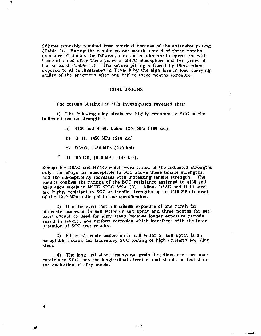
failures probably resulted from overload because of the extensive pl'.ting(Table 9). Basing the results on one month instead of three monthsexposure eliminates the failures, and the results are in agree,nent withthose obtained after three years in MSFC atmosphere and two years atthe seacoast (Tab_,e 10). The severe pitting suffered by D6AC whenexposed to AI is illustrated in Table 8 by the high loss in load carryingability of the specimens after one half to three months exposure.
CONCLUSIONS
The results obtained in this investigation revealed that:
1) The following alloy steels are highly resistant to SCC at theindicated tensile strengths:
a) 4130 and 4340, below 1240 MPa (180 ksi)
b) H-11, 1450 MPa (210 ksi)
e) D6AC, 1450 MPa (210 ksi)
m
d) HY140, 1020 MPa (140 ksi).
Except for D6AC and HY140 which were tosted at the indicated strengthsonly, the alloys are susceptible to SCC above these tensile strengths,and the susceptibility increases with increasing tensile strength. Theresults confirm the ratings of the SCC resistance assigned to 4130 and4340 alloy steels in MSFC-SPEC-522A [3]. Al.loys D6AC and H-11 steelare highly resistant to SCC at tensile strengths up to 1450 MPa insteadof the 1240 MPa indicated in the specification.
2) It is believed that a maximum exposure of one month foralternate immersion in salt water or salt spray and three months fbr sea-coast should be used for alloy steels because longer exposure periodsresult in severe, non-uniform corrosion which interferes with the inter-pretation of SCC test results.
3) Either alternate immersion in salt water or salt spray is anacceptable medium for laboratory SCC testing of high strength low alloysteel.
4) The long and short transverse grain directions are more sus-ceptible to SCC than the longit._dinal direction and should be tested inthe evaluation of alloy steels.
_m-qW
1980016917-009
REFERENCES
I. Humphries, T. S. : Procedures for Externally Loading and Corro-sion Testing Stress Corrosion Specimens. NASA TM X-53483,June 1966.
2. Sprowls, D. O., Summerson, T. J., Ugiansky, G. M., Epstein,S. G., and Craig, H. L., Jr.: Evaluation of a Proposed StandardMethod of Testing for Susceptibility to Stress-Corrosion Crackingof High-Strength 7XXX Series Aluminum Alloy Products. StressCorrosion-New Approaches, ASTM STP bl0, American Society forTesting and Materials, 1976, pp. 3-31.
3. Marshall Space Flight Center: Design Criteria for Stress CorrosionCracking. MSFC-SPEC-522A, November 18, 1977.
5
1980016917-010
TABLE I. CHEMICAL COMPOSITION OF THE TESTALLOY STEELS :
F/N Ratio of failures to number of specimens tested.Total exp_sure time was 3 months for AI and salt spray and14 month_ for seacoast.
9
1980016917-014
TABLE 5. SCC TEST RESULTS OF H-II STEEL
, |
Tensile Stress Environment
Stress Strength % AI _ ..Seacoast
Direction MPa ksi Y.S. F/N Days F/N Days F/__N Days
2.5 cm DIAMETER BAR
TR 1650 240 25 0/2 0/2
(C-Ring) 50 2/2 27,29 0/290 3/3 2,2,2 1/3 167
LO 1650 240 50 5/5 20-35 0/4
90 5/5 7-13 0/4
0.6 cm THICK PLATE
LT 1450 210 50 0/575 1/5 117
F/N Ratio of failures to number of spccimens tested.
Total exposure time was 3 months for AI, 6 months for MSFC atmosphere,and 2 years for seacoast.
TABLE 6. SCC TEST RESULTS OF HYI40 STEEl,
Tensile Stress Environment
Stress Strength % AI MSFC Atm Seacoast
Direction MPa ksi Y.S. F/N Days F/N Days F/N Days
LT 1020 148 75 0/3 0/3 0/3100 0/3 0/3 0/3
LO 1020 148 75 0/3 0/3100 0/3 0/3
F/N Ratio of failures to number of specimens tested.Totalexposuretime was 2 months forAI, 5 years forMSFC atmosphere,m_d 2 years for seacoast.
10
°l.am
] 9800 ] 69 ] 7-0 ] 5
TABLE 7. SCC TEST RESULTS OF D6AC STEEL i
Tensile Stress Envir(,mllcnt
Stress Strength o_ AI 1_IS I,'CArm Seacoast i-
DirectionM Pa ksi Y.S. F/N Days F/N Days F/N DaYs
D6AC STEEL - 0.9 cm AND 2.5 cm
THICK SECTIONS OF MOTOR CASE
LT 1450 210 40 0/5
45 0/5
50 1/_ 50 0/3 0/1055 1/5 77
60 1/5 86 _65 3/5 63,67,68
75 8/8 41-90 0/3 0/1090 O/3
LO 1450 210 45 0/550 0/3 0/:155 1/5 77
65 2/5 74,7775 3/3 58,71,86 0/3
! , • ,
F/N - Ratio of failures to numb(,r of specimens tested.Total exposure time was 3 months for AI, :l years l'or MSFC =atmosphere, and 2 years for seilpoast.
,+
y
J
ki
i:
!
11
• 41'%,8 ,I ,a
1980016917-016
TABLE 8. LOSS IN LOAD CARRYING ABILITY OF ALLOY STEELS
NOTE: (1) Total cxI_sum at the seacoast was 14 months except as noted:(a) 6 months (b) 24 months
17
1980016917-022
ORIGINAL PAOli I|oFPOORqu_un-f
1980016917-023
r!
ORIGINAL PAGE I_;OF. POOR QUALITY
19
.=_, ,,.1"
_m _t_am
1980016917-024
1980016917-025
21
1980016917-026
rl
2Z
1980016917-027
OR_GIT'I.,_Lm?,cT IS
OF POO,_ .-,,'tl,,:',,Lf_'
23
1980016917-028
APPROVAL
EVALUATION OF THE STRESS CORROSION CRACKINGHIGH STRENGTH LOW ALLOY STEE LS
By
T. S. Humphries and E. E. Nelson
The information in this report has been reviewed for technicalcontent. Review of any information concerning Department of Defenseor nuclear energy activities or programs has been made by the MSFCSecurity Classification Officer. This report, in its entirety, has beendetermined to be unclassified.
A
D. B. Franklin
Chief, Corrosion Research Branch
___Director, Materials & rocesses Laboratory
I_' U.S. GOVERNMENT PRINTING OFFICE: 1980-640-247/564 REGION NO. 4