Tech Report GIT-GVU-06-15 Surgem January 9, 2007 Surgem: Interactive patient-specific anatomy-editor for hemodynamic analysis and surgery planning Jarek Rossignac (1) , Kerem Pekkan (2) , Brian Whited (1) , Kirk Kanter (3) , Shiva Sharma (4) , Ajit Yoganathan (2) (1) GVU Center, Intelligent and Interactive Computing Division, College of Computing, Georgia Institute of Technology, Atlanta, Georgia. http://www.gvu.gatech.edu/~jarek/ (2) Cardiovascular Fluid Mechanics Laboratory, Wallace H. Coulter Department of Biomedical Engineering, Georgia Institute of Technology & Emory University School of Medicine (3) Department of Cardiothoracic Surgery, Emory University School of Medicine Abstract Surgem is an interactive anatomy-editing tool for surgery planning developed to enable the surgeon to directly edit the detailed models of patient-specific anatomies according to the contemplated surgical options and to compare such options by using the results of computational fluid dynamics (CFD) analysis. Surgem combines powerful free-form shape deformation tools with new human-shape interaction (HSI) technologies to facilitate interactive shape alterations and finite element mesh generation. Surgem is used by the surgeon at the surgery planning phase to design and evaluate possible modifications of patient-specific anatomies of congenital heart defects involving complex geometric topologies and tortuous three-dimensional blood flow pathways with multiple inlets and outlets. Surgem make it possible to freely deform the lumen surface and to bend and position baffles through direct manipulation of the 3D models with both hands, thus eliminating the tedious and time-consuming phase of entering the desired geometry using traditional computer-aided design (CAD) systems. The 3D models of the modified anatomy are seamlessly exported and meshed for CFD analysis. The combined design/analysis cycle is used for comparing and optimizing surgical plans. By reducing the cost of patient-specific shape design and analysis, Surgem make it possible to specify and analyze a large number of surgical options and to envision large clinical studies for validating the predictive value of CFD simulations in surgery planning. Fig. 1. Surgem is used to modify a patient’s intra-atrial model of the inferior vena cava (IVC) interactively using both hands to specify what may be the outcome of an operation envisioned by the heart surgeon. The envisioned shape is meshed and sent to CFD analysis. The results of the analysis help the surgeon select between various surgical options.
Transcript
Tech Report GIT-GVU-06-15 Surgem January 9, 2007
Surgem: Interactive patient-specific anatomy-editor for hemodynamic analysis and surgery planning
(1) GVU Center, Intelligent and Interactive Computing Division, College of Computing, Georgia Institute of Technology, Atlanta, Georgia. http://www.gvu.gatech.edu/~jarek/
(2)Cardiovascular Fluid Mechanics Laboratory, Wallace H. Coulter Department of Biomedical
Engineering, Georgia Institute of Technology & Emory University School of Medicine
(3)Department of Cardiothoracic Surgery, Emory University School of Medicine
Abstract Surgem is an interactive anatomy-editing tool for surgery planning developed to enable the surgeon to directly edit the detailed models of patient-specific anatomies according to the contemplated surgical options and to compare such options by using the results of computational fluid dynamics (CFD) analysis. Surgem combines powerful free-form shape deformation tools with new human-shape interaction (HSI) technologies to facilitate interactive shape alterations and finite element mesh generation. Surgem is used by the surgeon at the surgery planning phase to design and evaluate possible modifications of patient-specific anatomies of congenital heart defects involving complex geometric topologies and tortuous three-dimensional blood flow pathways with multiple inlets and outlets. Surgem make it possible to freely deform the lumen surface and to bend and position baffles through direct manipulation of the 3D models with both hands, thus eliminating the tedious and time-consuming phase of entering the desired geometry using traditional computer-aided design (CAD) systems. The 3D models of the modified anatomy are seamlessly exported and meshed for CFD analysis. The combined design/analysis cycle is used for comparing and optimizing surgical plans. By reducing the cost of patient-specific shape design and analysis, Surgem make it possible to specify and analyze a large number of surgical options and to envision large clinical studies for validating the predictive value of CFD simulations in surgery planning.
Fig. 1. Surgem is used to modify a patient’s intra-atrial model of the inferior vena cava (IVC) interactively using both hands to specify what may be the outcome of an operation envisioned by the heart surgeon. The envisioned shape is meshed and sent to CFD analysis. The results of the analysis help the surgeon select between various surgical options.
J. Rossignac et al. Surgem 2 / 11
1. Introduction Founded on three-dimensional (3D) anatomical image acquisition and advanced engineering analysis, patient-specific surgical outcome prediction and quantitative functional assessment methodologies have been proposed for a spectrum of cardiovascular applications [1-3]. These methodologies promise to be of value in clinical practice and in surgical decision making. However, their deployment has been hampered by the cost of designing the 3D models of the modified anatomies that would represent the results of the contemplated surgical options for each patient. This cost has been excessive, because mechanical CAD (Computer-Aided Design) systems, which have been traditionally used for this task, do not provide support for specifying the desired anatomical variation of 3D geometric models of the complexity of a cardiovascular system. We describe here how new shape-editing technologies have been harnessed to remove this design bottleneck and bring the computer-aided pre-surgical patient-specific outcome assessment to the next level of effectiveness, enabling its practical clinical use and advance the current surgical decision making process. These technologies promise to benefit other biomedical applications that also require a quantitative subject-specific manipulation of the complex geometry, spanning from cellular to organ level [4]; as in tissue engineering [5,6], cellular topology representation [7], customized bone/joint prosthesis [8-10], pediatric facial reconstruction [11] and medical device designs [12]. The tools described here fuel the emerging field of biological- and biomedical-CAD [13], which requires customized, flexible and robust approaches to handle three-dimensional, arbitrary, dynamic biological forms.
Unlike the perfect and uniform geometrical shapes designed in many traditional CAD/CAM applications, vascular anatomies are patient-specific and cannot be easily constructed as combinations of a small number of mathematically simple shape primitives or created by a sequence of digital counterparts of manufacturing operations. The shape modifications produced during surgical operations are closer to those a sculptor would envision. To model their effect, the surgeon must have total control over an intuitive and powerful human-shape interface. For these reasons, it is impractical and time-consuming to use existing engineering CAD tools in the emergent biomedical areas when attempting to facilitate systematic innovation in surgical design, vascular repair, palliative treatment planning or to enable multi-scale patient specific computational modeling for functional analysis. Geometrical challenges become even more prominent because these applications require the computational analysis of patient specific anatomies, whose geometry is modified from the acquired one either for automatic shape optimization or to explore different surgical options.
State-of-the-art engineering CAD tools are used in patient-specific analysis studies, but are limited in functionality and flexibility, lacking basic geometry operations important to support the interactive modification of complex biological shapes to reflect what could happen during an operation. A new set of CAD tools is clearly required for biomedical applications to address the demanding needs of cardiovascular surgery planning and assessment. We describe a human-shape interaction system, called Surgem that is based on two-hand free-form manipulation, and report its applications to the surgery planning and hemodynamic analysis of complex congenital heart defects.
2. Geometrical Foundations and Technology A collaboration between cardiothoracic surgeons, biomedical engineers, and computer scientists has led to the development and customization of a state-of-the-art 3D human-shape interaction tools for the virtual surgical planning of complex pediatric heart surgeries for the benefit of single-ventricle patients [14]. Building upon the early explorations of motion and shape design and of user interfaces for free-form deformations of 3D shapes, we have developed a surgical design environment, called Surgem, which provides intuitive operations for complex vascular anatomy editing, in preparation for flow analysis and surgery planning. The realtime shape editing capabilities of Surgem are based on a mathematical model of free-form deformations (FFD) that are weighted averages of pose-interpolating screw motions [15,16], originally developed for editing motions that interpolate user-specified position and orientation constraints. This mathematical tool is integrated with a new Human-Shape Interaction (HSI) methodology that uses two commercially available six degrees of freedom (DoF) trackers to control the parameters of the FFD by simple and natural gestures of both hands [17-19]. As a result, Surgem supports the intuitive manipulation of shape with both hands through natural gestures that grab, move, bend and twist the desired portion of the shape.
3. Applications – Pediatric Cardiac Surgeries Snapshots of the first generation anatomical editing/sculpturing hardware and software implementation is shown in Fig. 1 as applied to the modification of an intra-atrial total cavopulmonary connection (TCPC) anatomy. Two magnetic trackers or robot-arms (see Fig 2) allow 3D anatomical orientation and interactive deformation of the anatomy model with high efficiency and comfort. As the surgeon moves both hands, the arteries deform in real-time to follow the constraints defined by the displacement and orientation changes in both trackers. The chosen shape modification can be frozen and easily exported to computational fluid dynamics (CFD) analysis. Transfer of surface files between the in-house MRI image reconstruction tools and Surgem is done via STL or Wavefront files. The resulting surfaces are then used to generate a grid
J. Rossignac et al. Surgem 3 / 11
for CFD studies. In order to provide the realtime response needed for the graphical feedback during direct manipulation, vessel material properties are not simulated. Instead, interactive operations allow the surgeon to quickly design the desired shapes that may reflect the outcome of a possible plan for the surgery while taking into account the various spatial, physical, and operational constraints anticipated during surgery.
Fig. 2. The user holds a magnetic tracker (left) or a robot-arm (right) in each hand and uses them to grab, warp, and bend the 3D model through simple gestures guided by the realtime graphics feedback.
3.1 Anatomical Sculpturing – Free-Form Lumen Surface Deformations In our earlier work, CFD tools were employed to answer clinical questions by altering the 3D MRI anatomy model without in vivo execution. Anatomical modifications include virtual pulmonary artery (PA) angioplasty or fenestration [20], and for a bilateral superior vena cava (SVC) Fontan, the virtual inferior vena cava (IVC) location modification for the hope of a better perfusion at the PA segment bounded by the two SVCs, [21]. While both of these operations were conceptually and geometrically simple (uniform dilatation and linear IVC translation), realizing these in the computer medium with the state-of-the art commercial CAD systems (like IDEAS, ProEngineer, Geomagics), introduced enormous difficulties. Each of these modifications required two to four weeks of manual anatomy editing using the CAD systems. As a comparison, several more complex anatomical modifications took only about 10 minutes to realize routinely, in a single interactive session using Surgem, Figure 3. These simulate inclusion of autologous tissue patches to construct desired size of flares and reorientations of the major vessel for the hope of augmenting the left or right lung perfusion. CFD studies and hemodynamic performance predictions of these modified anatomies are in progress and will be presented in a follow-up study.
Fig. 3. Three patient-specific models and their selected free-formed deformed modifications (right two columns) generated using Surgem starting from the original 3D anatomical MRI reconstructions (left-most column). Interactive anatomical changes are pointed by arrows, which include removal of the connection pouch, addition of various flares at LPA/RPA and IVC, dilation of RPA/LPA branch stenosis and modifications on the SVC confluence. First two rows are typical second-stage surgical pathways (Hemi-Fontan (top) and Glenn (middle)), bottom row is a last-stage bilateral-Fontan connection.
J. Rossignac et al. Surgem 4 / 11
3.2 Interactive Baffle Creation and Positioning Congenital heart defects are surgically repaired through a series of palliative operations [22,23]. The final stage
surgical operation involves the connection of inferior vena cava (IVC) to pulmonary artery (PA) through an end-to-side anastomosis. Either an autologous partial conduit (intra-atrial) or a uniform diameter PTFE baffle (extra-cardiac) is used in this connection. Exact location and size of this conduit is determined at the time of the open-heart surgery and require anatomy specific customization, trial and error. Left to surgeon’s artistic capability this approach can extend the cardiopulmonary bypass time, which can cause injury to vital organs (the brain, kidneys, lungs, and heart) -a problem seen in up to 30% of postoperative pediatric patients.
Fig. 3. Left: IVC baffle configurations sketched by three pediatric cardiac surgeons in sagital and coronal views. Right column is the 3D reconstructions of each design virtually in the computer by the surgical planning tool.
Upon requests from the surgeons, new functionality was introduced to Surgem, to facilitate the computer aided
construction of uniform diameter IVC baffle, which can be interactively modified as desired and located in the 3D space, by holding each end of the baffle with one hand and moving and bending them into the proper shape. The virtual IVC baffle is a circular cross-section tube whose spine (central axis) is represented by piecewise circular curve [24], a space curve made by smoothly joined circular arcs. Hence, the baffle is composed of smoothly abutting sections of tori. The user may grab, pull, bend, and twist the ends of the baffle or any junction between consecutive arcs. Furthermore, arcs may be split to provide local editing flexibility.
Three pediatric cardiac surgeons kindly provided their surgical sketches of the IVC baffle construction for a given Glenn stage (pre-surgery anatomy) reconstruction. Reconstruction information included the low resolution representations of the land mark anatomies such as the IVC, pulmonary veins, aorta and the heart. These sketches were turned into 3D models with Surgem, Fig 3, and saved for comparative CFD analysis studies. Virtual anatomy design also enabled the construction of the IVC baffle in different diameters for the fixed 3D orientation to asses the fluid dynamic benefit of using
J. Rossignac et al. Surgem 5 / 11
larger conduits. Additionally, any region of the anatomy can be marked interactively to represent surgical patches, suture lines or conduits and their geometrical properties can be calculated. These highlighted regions can also be exported as standalone surfaces for further specific analysis and measurement, Fig 4. For example, in pediatric cardiac surgeries estimation of the size of a Dacron patch to be sutured requires trial-and-error even for an experienced surgeon. The developed patch size calculated in Surgem and compensated for vessel deformation will be potentially useful for the surgeon at the operating room.
Fig. 4. The surgical patch is interactively highlighted with red color using magnetic trackers on the complex anatomy which is then exported as a standalone lumen surface for further analysis. For this example suture length and the area of the autologous patch that will be needed during surgery is calculated.
4. Technical details The starting point of the underlying technology stems from an attempt to produce a tool for virtual sculpturing. The idea is to let the user grab a portion of the shape and then pull, push, twist, and bend it, Figure 5. Only the portion of the shape in the vicinity of the grabbed point is affected. The effect is lessened with distance through a specified decay profile. The objective is to simulate such an interaction allowing the surgeon to use both hands simultaneously in two possible modes: either one hand controls the position and orientation of the entire model while the dominant hand grabs, pulls, twists a detail or both hands work together at shaping the local geometry. Fig. 5. Elemental interactive free-formed deformations (b: pull, c: twist, d: bend) simulating a sculptures putty (a).
The fundamental shape editing capability of Surgem is based on a particular mathematical model of a warp, Figure
5, that leads to intuitive and effective shape response to the editing motion. For example, in the simplest editing mode, each hand manipulates a tracker that records 6 degrees of freedom (3 coordinates for position and 3 angles of rotation). Each tracker controls a local coordinate system (called a pose), defined by a position and an orientation. When the user presses a button of the tracker, the left and right starting poses (SL and SR) are recorded. Then, during editing, the current positions of the trackers define the end poses (EL and ER). End poses change continuously during manipulation (until the button is released). During shape editing, at each frame, a space warp (W) is computed and applied to the 3D shape being manipulated. The warp that satisfies the 12 position and orientation constraints simultaneously for the two grabbed poses
J. Rossignac et al. Surgem 6 / 11
(W(SL)=EL, W(SR)=ER) and produces a smooth warp in the vicinity of the grabbed points. When the button is released, the deformation is frozen and the user may proceed to the next free-form surface modification operation.
After experimenting with a variety of free-form deformation techniques, we have selected to compute a screw warp [17] for each hand and to blend them into a global warp that simultaneously satisfies all position and orientation constraints. Note that our choice was motivated by the need to provide a natural (i.e. predictable) and effective deformation tool through which the surgeon can manipulate the 3D model through natural gestures, focusing on the desired shape changes, not on user interface options, coordinate systems, or abstract parameters that control mathematical warps. Furthermore, we needed the warps to respond to continuous motions of the trackers in realtime, updating the deformed shape and its image on the screen at more than 20 frames per second. These objectives have precluded us from supporting physically based deformations that would mimic the behavior of real vessels. Instead, we rely on the surgeon’s experience to create the desired shapes by direct manipulation. The objective of Surgem is to replace the current process where the surgeon draws the contemplated shape change on paper and asks an operator to create it in a CAD system. We strive to provide an environment that would eliminate both the ambiguous pencil drawing and the tedious and time consuming CAD entry, and replace them by a new process in which the surgeon can edit the patient’s anatomy directly.
A screw warp first computes a screw motion for each tracker that interpolates between a start and end pose of that tracker. Then, for each vertex in the vicinity of the point grabbed by one or the other hand, it computes a weight for each screw and applies the corresponding fraction of that screw motion. We provide the details of the underlying mathematical models.
First, we focus on the computation of each screw. Using a screw motion, Figure A3, has many advantages: A minimal screw motion between S and E minimizes rotation angle and translation distance and is independent of the choice of the coordinate system and of the trajectory used to define S and E. The screw motion combines a rotation by angle b around an axis through point A parallel to vector K with a translation by dK. The parameters K, b, d, and A of such a screw motion may be computed quickly as explained below.
Fig. 6. Kinematics of the screw motion interpolating start (S) and end (E) poses.
Let the grab pose be defied as [O, I, J, K] by the grabbed point O and the orthonormal coordinate system [I, J, K].
The release pose is defined as [O’, I’, J’, K’]. We compute the screw parameters in 4 steps. K:=(I’–I)×(J’–J), K:=K / ||K|| <1> d:=K•OO’ <2> b := 2 sin–1(||I’–I|| / (2 ||K×I||) ) <3> A:=(O+O’)/2 + (K×OO’) / (2tan(b/2)) <4>
Let us justify each step.
Step <1>: For simplicity, assume that the cross-product (I’–I)×(J’–J) is not a null vector. (If it is, simultaneously permute the names in [I, J, K] and [I, J, K]. If all permutations yield a null vector, the screw is a pure translation.)
Step <2>: Clearly, the displacement d along K is the signed distance between the projections of O and O’ onto the axis. Hence d is computed as the dot product (projection) of OO’ onto K.
Step <3>: To compute the angle b, consider the triangle made by the projections Ip and I’p of I and I’ onto the plane orthogonal to K (Fig. Ab3) and note the ||Ip||=||I’p||=||K×I|| by definition of the cross-product and that ||I’p–Ip||=||I’–I||, since I’–I is orthogonal to K. Then, as shown in Fig. 6, sin(b/2)=(||I’–I||/2)/||K×I||.
J. Rossignac et al. Surgem 7 / 11
Step <4>: Given the projections P and P’ of O and O’ onto a plane normal to K and given, we want to compute the center Q of rotation by angle b=2a that brings P to P’. Consider the midpoint M=(P+P’)/2 and the vector T=N×PP’/||PP’|| in that plane that is normal to PP’. We find a point Q on that plane such that the angle (QP,QP’) is 2a. We know that Q lies on the median of P and P’ and hence need to find c such that Q=M+cT. As shown in Fig. 7, c=||PP’||/(2tan(a)). Hence, Q=(P+P’)/2+N×PP’/(2tan(a). Let us choose the plane for this construction to contain the point (O+O’)/2. By construction of the projections: P=O+hK and P’=O’–hK. Now, note that P+P’=O+O’ and that PP’=OO’–2hK. Therefore, K×PP’= K×OO’– 2hK×K = K×OO’. Hence: A = (O+O’)/2 + K×OO’/(2tan(b/2).
Fig. 7. Kinematics of the screw motion interpolating start (S) and end (E) poses.
Now, let us discuss the decay functions. The decay function for each tracker takes as parameter the distance between a surface point P and the grabbed point OL (left hand grab) or OR (right hand grab). We apply to each vertex a weighted combination of two screw motions. A left motion that maps the grabbed pose SL to the current or end pose EL and a right motion that maps SR to ER is computed. Then, a fraction of each motion is applied to all points of the shape that fall within the region of influence. The fraction between 0 and 1 is provided by the decay function. The decay function of a single hand is radial (i.e., a function of the distance to the grabbed point). To ensure a smooth transition, a cosine square function is chosen as the decay profile (see Fig. 8).
Fig. 8. Region of influence centered on the grabbed point O, allows localized surface deformations. L is the rigid body motion operator connecting the start (SL) and end (EL) poses of the left hand. The grabbed point is subject to the whole motion L(1). The effect of both hands is combined by adding the displacements of each region of influence (RoI) Figure 9. Points in the RoI of both hands will be displaced by fractions of each screw. To produce a smooth and natural displacement in the common region and to guarantee that the 6 constraints imposed by each hand are satisfied, the RoIs are squashed so that each excludes the center of the other. Applying a screw motion to the vertices of a model may be done in realtime (20 frames per second) for large models with thousands of vertices. Each vertex is transformed by a fraction of the screw. The fraction is computed as a function of the distance from he vertex to the grabbed point using the decay function.
J. Rossignac et al. Surgem 8 / 11
Fig. 9. The two-hand warp for simultaneously deform a given shape. (a) Three instances from a basic two-hand warp operation. (b) Vector addition at the intersecting regions of influence. Distinct (c) and intersecting (d) regions of influence of the left and right hands.
The one-hand or two-hand warps supported by the free-form deformation model described above are extremely
useful for local deformations of a surface, but are ill-suited for bending vessels. Hence, we use the Bender approach [18], which extends the simple spherical RoI to a user-controlled tube for bending tubular surfaces. Bender simulates a flexible ribbon that is held by the user at both ends and may be moved, stretched, twisted and bent, Figure 10. It can be positioned anywhere with respect to the model. When a button on the tracker is pressed, the shape of the grabbed ribbon is captured. A deformation that maps it into the current ribbon (continuously changing during editing) or the final ribbon (frozen upon release) is computed, applied to the shape in realtime and rendered at each frame. Real-time video recordings of two anatomical editing and sculpturing sessions are available on the web [28][29].
Fig. 10. The BENDER tool. Allowing surface deformations along an interactive curved ribbon of influence.
J. Rossignac et al. Surgem 9 / 11
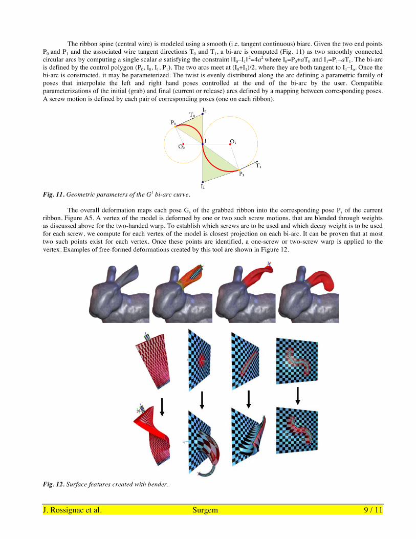
The ribbon spine (central wire) is modeled using a smooth (i.e. tangent continuous) biarc. Given the two end points P0 and P1 and the associated wire tangent directions T0 and T1, a bi-arc is computed (Fig. 11) as two smoothly connected circular arcs by computing a single scalar a satisfying the constraint ||I0–I1||2=4a2 where I0=P0+aT0 and I1=P1–aT1. The bi-arc is defined by the control polygon (P0, I0, I1, P1). The two arcs meet at (I0+I1)/2, where they are both tangent to I1–Io. Once the bi-arc is constructed, it may be parameterized. The twist is evenly distributed along the arc defining a parametric family of poses that interpolate the left and right hand poses controlled at the end of the bi-arc by the user. Compatible parameterizations of the initial (grab) and final (current or release) arcs defined by a mapping between corresponding poses. A screw motion is defined by each pair of corresponding poses (one on each ribbon).
Fig. 11. Geometric parameters of the G1 bi-arc curve.
The overall deformation maps each pose Gs of the grabbed ribbon into the corresponding pose Ps of the current
ribbon, Figure A5. A vertex of the model is deformed by one or two such screw motions, that are blended through weights as discussed above for the two-handed warp. To establish which screws are to be used and which decay weight is to be used for each screw, we compute for each vertex of the model is closest projection on each bi-arc. It can be proven that at most two such points exist for each vertex. Once these points are identified, a one-screw or two-screw warp is applied to the vertex. Examples of free-formed deformations created by this tool are shown in Figure 12.
Fig. 12. Surface features created with bender.
J. Rossignac et al. Surgem 10 / 11
5. Discussion and Conclusions State-of-the-art patient specific analysis methodology is well developed in all aspects including, PC-MRI and MRI reconstruction, grid generation, experimental validation, computational analysis and post-processing. Advances in this field now allow fast hemodynamic performance analysis of a given anatomy with fixed morphology routinely. The missing block that needs immediate attention is the surgical planning and morphological design. This involves creation of alternative anatomies and manipulation of anatomies that are changing, either by the user, interactively or during an automated optimization process of inverse design. Similarly vascular growth and development involve complex series of morphological changes which can be analyzed and represented robustly with the presented Bio-CAD approach. Models with anatomical variations are also needed for verification tests of computational models. For example, in CFD model verification studies, families of anatomical models are routinely needed to test effects of inlet vessel pathway shape to the patient specific CFD results. Furthermore registration of a medical device (like an aortic canula, mechanical valve or a drug eluding stent) with respect to a given complex patient-specific anatomy is occasionally required for computational modeling. Creation of such alternative morphologies and complex anatomical design/registration operations can become considerably straightforward with the tools presented in this paper. Similar to the reconstructive pediatric cardiac surgeries the presented tools are expected to be useful in other biomedical applications including mitral valve repair [25] and ventricle reconstruction surgeries [26].
Our interactions with cardiac surgeons and cardiologists identified the key technologies that need to be developed and integrated in to Surgem. These geometrical modeling concepts and surgical planning tools are prioritized and include; 1) Patch Augmentation and Virtual Balloon Angioplasty Tool. An improved local vessel dilatation tool for virtual repair of stenosed vessels. 2) Standard graft database. A selection of standard grafts to be used during the IVC vessel reconstruction will be available. 3) Helpful Editing and Bookkeeping Features: (i) A local measurement tool of diameters, distances, areas marked areas of the vessel surface. (ii) Introducing vessel labels. (iii) Selective use of colors and transparency for identifying different materials; veins, arteries, grafts. (iv) On vessel lumen drawing of surgical marks for identifying the anastomosis lines. (v) Marking selected regions of the anatomy as stationary and locking these regions to avoid any accidental changes (The inlet/outlet surfaces should be smooth and planar for finite-element analysis. Lock these regions as stationary to keep their shape constant). (vi) Streamlined data export to computational fluid dynamics analysis. 4) Automated generation of a family of vessel anatomies as a function of the generator curve arc-length in between the two given start and end locations for parametric optimization studies. 5) As most surgical reconstructions are created on cardiopulmonary bypass without blood flow, the geometric shape should be assessed and visualized in the post-bypass hydrostatic loading condition [27].
Advanced patient-specific analysis techniques could potentially be useful in the clinical evaluation of complex patient hemodynamics. Increase in efficiency and robustness of this type of analysis will eventually enable assessment of the predictive value of CFD simulation in clinical practice through prospective testing in large number of patients before and after intervention. Next-generation biological computer aided shape design tools that are founded on advanced geometry processing and specifically developed for arbitrary, time-varying, complex/flexible cardiovascular anatomies targeting biological complexity can enable virtual cardiovascular surgeries efficiently and provide an alternative environment for patient-specific and custom virtual surgeries—without in vivo execution. Besides providing quantitative pre-surgery functional assessment of the intended operation, these tools may also be useful for surgical training and for innovating new technologies and techniques for treatment on the computer medium. Robust complex geometry handling capability will allow the surgeon, cardiologist or the biomedical engineer to interact with the anatomy, propose changes, quantify them and test their effect. Manipulating biological systems and tissues in a computer setting (through bio-CAD systems as a design tool) offers opportunities for further innovations and new surgical concepts.
6. Acknowledgements We wish to thank Drs. Mark Fogel, William Gaynor at the Children’s Hospital of Philadelphia, Dr. Pedro del Nido – Boston Children’s Hospital, Paul Krishborn - Emory University and Dr. W. James Parks at Sibley Heart Center, Egleston Children’s Hospital/Emory University, Atlanta, for their guidance during the early stages of the design of the Surgem tool. We also with to thank students Ignacio llamas, ByungMoon Kim, and Alex Powell for their contributions to the development of the Twister and Bender technologies upon which Surgem was built. Finally, this work was supported in part by Grant # R01HL67622 from the National Heart, Lung and Blood Institute and by a Seed Grant from the Graphics Visualization and Usability (GVU) Center at Georgia Tech.
J. Rossignac et al. Surgem 11 / 11
7. References 1. Steinman DA, (2004) Image-based computational fluid dynamics: a new paradigm for monitoring hemodynamics and
atherosclerosis, Curr Drug Targets Cardiovasc Haematol Disord, 4(2):183-97. 2. Moore S, David T, Chase JG, Arnold J, Fink J, (2006) 3D models of blood flow in the cerebral vasculature, Journal of
Biomechanics, In Press available online. 3. Pekkan K, de Zelicourt D, Ge L, Sotiropoulos F, Frakes D, Fogel MA, Yoganathan AP, (2005) Physics-driven CFD
modeling of complex anatomical cardiovascular flows-a TCPC case study, Annals of Biomedical Engineering 33(3):284-300.
4. Hunter P, Smith N, Fernandez J, Tawhai M, (2005) Integration from proteins to organs: the IUPS Physiome Project, Mech Ageing Dev 126(1):187-92.
5. Sun W, Lal P, (2002) Recent development on computer aided tissue engineering - a review, Computer Methods and Programs in Biomedicine 67: 85-103.
6. Porter B, Zauel R, Stockman H, Guldberg R, FyhrieD, (2005) 3-D computational modeling of media flow through scaffolds in a perfusion bioreactor, Journal of Biomechanics 38(3):543-549.
7. Yin Y, Chen Y, Ni D, Shi H, Fan Q, (2005) Shape equations and curvature bifurcations induced by inhomogeneous rigidities in cell membranes, Journal of Biomechanics 38(7):1433-1440.
8. Testi D, Quadranib P, Petroneb M, Zannonib C, Fontanac F, Vicecontia M, (2004) JIDE: a new software for computer-aided design of hip prosthesis, Computer Methods and Programs in Biomedicine 75: 213-220.
9. Mackerle J, (2004) Finite Element Modelling and Simulations in Dentistry: A Bibliography 1990–2003, Computer Methods in Biomechanics and Biomedical Engineering 7(5): 277–303.
10. Lin YP, Wang CT, Dai KR, (2005), Reverse engineering in CAD model reconstruction of customized artificial joint, Med Eng Phys. 27(2):189-93.
11. Sheppard LM, (2005), Virtual Surgery Brings Back Smiles, IEEE Comput Graph Appl. 25(1):6-11. 12. Labrossea MR, Bellerb CJ, Robicsekc F, Thubrikard MJ, (2006) Geometric modeling of functional trileaflet aortic
valves: Development and clinical applications Journal of Biomechanics, In Press available online. 13. Sun W, Editorial, (2005) Bio-CAD, Computer-Aided Design 37(11): 1095-1096. 14. de Leval MR, (1998) The Fontan circulation: What have we learned? What to expect? Pediatr Cardiol. 19(4):316-20. 15. Kim J, Rossignac J, (2000), Screw motions for the animation and analysis of mechanical assemblies, International
Journal of the Japan Society of Mechanical Engineers, 2000. 16. Kim BM, Rossignac J, (2003) Collision Prediction for Polyhedra under Screw Motions, ACM Symposium in Solid
Modeling and Applications, pp. 4-10. 17. Llamas I, Kim B, Gargus J, Rossignac J, Shaw C, (2000), Twister: A space-warp operator for the two-handed editing of
3D shapes, ACM Transactions on Graphics (TOG), pp. 663-668. 18. Llamas I, Powell A, Rossignac J, Shaw C, (2005), Bender: A Virtual Ribbon for Deforming 3D Shapes in Biomedical
and Styling Applications, 2005, ACM Symposium on Solid and Physical Modeling (SPM). GVU Tech. Report GIT-GVU-04-25.
19. Video: http://a-lex.powelltown.com/BenderClipsSmall.mov 20. Pekkan K, Kitajima H, Forbess J, Fogel M, Kanter K, Parks WJ, Sharma S, Yoganathan AP, (2005) TCPC Flow with
Functional Left Pulmonary Artery Stenosis – Fenestration and Angioplasty in Vitro, Circulation, 112: 3264-71. 21. Zélicourt D, Pekkan K, Parks WJ, Kanter K, Fogel M, Yoganathan AP, (2006) Flow study of an extra-cardiac
connection with persistent left superior vena cava, The Journal of Thoracic and Cardiovascular Surgery, 131(4), to appear.
22. Welke KF, Komanapalli C, Shen I, Ungerleider RM, (2005) Advances in congenital heart surgery, Curr Opin Pediatr, 17(5):574-8.
23. Mitchell ME, Ittenbach RF, Gaynor JW, Wernovsky G, Nicolson S, Spray TL, (2006), Intermediate outcomes after the Fontan procedure in the current era, J Thorac Cardiovasc Surg. 131(1):172-80.
24. Rossignac J, Requicha A, (1987), Piecewise-Circular Curves for Geometric Modeling, IBM Journal of Research and Development 13: 296-313.
25. Yacoub MH, Cohn LH, (2004), Novel approaches to cardiac valve repair: from structure to function: Part I., Circulation. 109(8):942-50.
26. Sartipy U, Albage A, Lindblom D, (2005), The Dor procedure for left ventricular reconstruction. Ten-year clinical experience, European Journal of Cardio-thoracic Surgery 27: 1005–1010.
27. Gu H, Chua A, Tan B, Hung KC, (2006), Nonlinear finite element simulation to elucidate the efficacy of slit arteriotomy for end-to-side arterial anastomosis in microsurgery, Journal of Biomechanics 39(3):435-443.