20

Geotechnical Data Report for 30% DesignMid Barataria Diversion Project (BA-153) Plaquemines Parish, Louisiana
forHDR Engineering, Inc.
January 24, 2014
Earth Science + Technology
DRAFT
DRAFTGeotechnical Data Report for 30% Design
Mid Barataria Diversion (BA-153)
Plaquemines Parish, Louisiana
for
HDR Engineering, Inc.
January 24, 2014
11955 Lakeland Park Boulevard, Suite 100
Baton Rouge, Louisiana 70809
225.293.2460
"Confidential Information; Privileged & Confidential Work Product"

DRAFT
Geotechnical Data Report for 30% Design
Mid Barataria Diversion Project (BA-153)Plaquemines Parish, Louisiana
LDNR Contract No. 2503-13-59, Task No. 3
File No. 18274-001-00
January 24, 2014
Prepared for:
HDR Engineering, Inc.201 Rue Iberville, Suite 115Lafayette, Louisiana
Attention: Mark Stanley, PE, GESenior Technical Advisor - Geotechnical
Prepared by:
GeoEngineers, Inc.11955 Lakeland Park Boulevard, Suite 100Baton Rouge, Louisiana 70809225.293.2460
Michelle L. Ramos, PESenior Geotechnical Engineer
Venu Tammineni, PE, LEED APGeotechnical Engineer
David S. Eley, PEPrincipal
Charles L. Eustis, PEPrincipal
MLR:VT:DSE:CLE:tlm
Disclaimer: Any electronic form, facsimile or hard copy of the original document (email, text, table, and/or figure), if provided, and any attachments areonly a copy of the original document. The original document is stored by GeoEngineers, Inc. and will serve as the official document of record.Copyright© 2014 by GeoEngineers, Inc. All rights reserved.
"Confidential Information; Privileged & Confidential Work Product"
DRAFT
MID BARATARIA DIVERSION (BA-153) Plaquemine Parish, Louisiana
January 24, 2014 | Page iFile No. 18274-001-00
Table of Contents
INTRODUCTION..............................................................................................................................................1
PROJECT AND SITE UNDERSTANDING........................................................................................................1
SITE DESCRIPTION........................................................................................................................................2
GEOLOGIC HISTORY ......................................................................................................................................3
GEOLOGIC DEPOSITION DESCRIPTIONS.....................................................................................................3
Point Bar................................................................................................................................................. 4
Natural Levee......................................................................................................................................... 4
Nearshore Gulf ....................................................................................................................................... 4
Abandoned Distributary......................................................................................................................... 4
Undifferentiated Interdistributary/Intradelta ....................................................................................... 4
Prodelta .................................................................................................................................................. 4
Pleistocene............................................................................................................................................. 4
Marsh...................................................................................................................................................... 5
30% DESIGN PHASE EXPLORATION PROGRAM.........................................................................................5
General ................................................................................................................................................... 5
Permits and Right-of-Entry..................................................................................................................... 5
Quality Control, Safety, and Other Plans ..............................................................................................5
Field Investigation.................................................................................................................................. 6
LABORATORY TESTING .................................................................................................................................9
LIMITATIONS..................................................................................................................................................9
TECHNICAL REFERENCES......................................................................................................................... 10
FIGURES
Figure 1. Vicinity Map
Figure 2. Surficial Geology, Topography and Project Elements
Figure 3. Field Investigation Locations
APPENDICES
Appendix A. Reference Information
Appendix B. Quality Control, Safety and Other Plans
Quality Program
Project Site Specific Work Plan
Best Management Practices
List of ASTM Standards
Appendix C. Field Exploration – River (Sta. 0+00 to 26+00)
Soil Boring Logs
Soil Boring Plates
Appendix D. Field Exploration – Land (Sta. 26+00 to Sta. 140+00)
Soil Boring Logs
Soil Boring Plates
CPT Logs
"Confidential Information; Privileged & Confidential Work Product"

DRAFT
MID BARATARIA DIVERSION (BA-153) Plaquemines Parish, Louisiana
Page ii | January 24, 2014 | GeoEngineers, Inc.File No. 18274-001-00
Field Vane Test Results
Appendix E. Field Exploration – Marsh (Sta. 140+00 and above)
Soil Boring Logs
Summary of Strength Data
Appendix F. Laboratory Testing Results – River (Sta. 0+00 to 26+00)
Summary of Laboratory Results – Grain Size Distribution
Summary of Laboratory Results – Moisture, Unit Weight, Strength Tests and Atterberg Limits
Sediment Geotechnical Properties
Laboratory Test Data – Individual Borings
Appendix G. Laboratory Testing Results – Land (Sta. 26+00 to Sta. 140+00)
Summary of Laboratory Results – Grain Size Distribution
Summary of Laboratory Results – Organic Content, Permeability
Summary of Laboratory Results – Moisture, Unit Weight, Strength Tests and Atterberg Limits
Laboratory Test Data – Individual Borings
Appendix H. Laboratory Testing Results – Marsh (Sta. 140+00 and above)
Summary of Laboratory Results – Grain Size Distribution
Summary of Laboratory Results – Organic Content, Fiber Content, Permeability
Summary of Laboratory Results – Moisture, Unit Weight, Strength Tests and Atterberg Limits
Mini-Vane Test Results
Laboratory Test Data – Individual Borings
Appendix I. Consolidation Test Data
Land
Marsh
Appendix J. Standard Penetration Test Hammer Calibration Results
Appendix K. Report Limitations and Guidelines for Use
ATTACHMENT
Compact Disk with Photographs of Sample Tubes/SPT Soil Samples
"Confidential Information; Privileged & Confidential Work Product"

DRAFT
MID BARATARIA DIVERSION (BA-153) Plaquemine Parish, Louisiana
January 24, 2014 | Page 1File No. 18274-001-00
INTRODUCTION
This report provides geotechnical data for the Mid Barataria Diversion (MBD) Project (BA-153) 30%
design in accordance with the scope of services presented in the Office of Coastal Protection and
Restoration Authority (CPRA), task order 0300 under the LADNR Contract No. 2503-13-59 and our
proposal dated January 29, 2013 (Phase 1 scope of services only). GeoEngineers, Inc.
(GeoEngineers) is subcontracted to HDR, Inc. (HDR) for the MBD project. The MBD is a large-scale,
long-term Mississippi River diversion structure project recommended for implementation in
Louisiana’s Comprehensive Master Plan for a Sustainable Coast. The project is located near Myrtle
Grove, in Plaquemines Parish, Louisiana (Vicinity Map, Figure 1).
Previous work performed by GeoEngineers included a study and review of available geologic
information. This work was completed in the early part of 2013 and helped establish the basis for
our 30% design scope. Previous studies were presented in our “Report of Existing Geotechnical
Data” dated May 22, 2013 (re-issued with additional information on January 17, 2014).
This report contains a site geology description, site plans with soil boring locations, and field data
and laboratory test results. Appendix A contains regulatory permits and Appendix B contains the
project quality control, safety and other plans. Descriptions of our field investigation for the river,
land and marsh along with individual soil boring logs are included in Appendices C through E.
Laboratory test results for the river, land and marsh borings are included in Appendices F
through H, respectively.
A geotechnical description of the subsurface conditions and our data interpretation is provided in
the “Geotechnical Baseline Report for 30% Design” submitted as a standalone report for the
project.
PROJECT AND SITE UNDERSTANDING
The MBD project is a large scale, engineered river diversion that will restore the natural over-land
flooding cycle of the Mississippi River and Tributaries (MR&T). The MBD project will consist of the
following elements as shown on Surficial Geology, Topography and Project Elements, Figure 2:
1. A diversion structure consisting of a channel into the Mississippi River and through the MR&T
levee with levee tie-ins and gates to control flow.
2. A conveyance channel approximately 8,000 feet long with guide levees (conveyance complex)
that extends west from the diversion structure to the existing back levee at the western edge of
the agricultural land between the two levees. The existing back levee is currently being rebuilt
to meet federal levee standards.
3. A storm surge protection structure at the back levee to prevent storm surges from entering the
conveyance channel.
4. A new pump station located about 5,500 feet north of the diversion complex near the back
levee.
5. An outfall area west of the back levee where sediment diverted from the Mississippi River will
settle.
"Confidential Information; Privileged & Confidential Work Product"

DRAFT
MID BARATARIA DIVERSION (BA-153) Plaquemines Parish, Louisiana
Page 2 | January 24, 2014 | GeoEngineers, Inc.File No. 18274-001-00
6. A new Louisiana Highway 23 (LA 23) bridge to span the conveyance complex.
7. A new railroad bridge for an extension of an existing railroad spur that will cross the
conveyance complex.
As shown on Figure 2, the surficial geology of the site is complex and reflects the different
subsurface soil conditions across the project site. The scope of work for the 30% design
exploration program was developed based on design requirements for each structure (as of the
time of scoping) and expected geologic conditions shown on Figure 2. The intent of the 30%
design geotechnical explorations was to evaluate subsurface soil conditions and provide design
soil parameters. Figure 2 also presents the project stationing and the topography across the
project area.
For the 30% design exploration program, the geotechnical investigation focused on the soil
conditions at the diversion structure, the conveyance complex, the storm surge protection structure
and the Barataria Bay marsh. We did not investigate the LA 23 overpass, the rail overpass, or the
pump station in the 30% geotechnical investigation. At the time of the investigation the location of
these features had not yet been determined and was likely to change based on the 30% design for
the diversion complex.
SITE DESCRIPTION
The diversion complex is bounded on the east by the Mississippi River and on the west by the
Barataria Bay marsh. Within these limits the conveyance complex alignment crosses LA 23 at
approximate Station (Sta.) 65+00. LA 23 is a 4-lane divided highway that extends south to Venice,
Louisiana and is the primary evacuation route for Plaquemines Parish. East of LA 23 to the MR&T
levee the site is forested. West of LA 23 to the back levee, the site is predominantly agricultural
fields that are currently used for livestock grazing. A railroad spur runs along the protected toe
(west side) of the MR&T levee.
The natural site grade gently slopes from the Mississippi River where the ground elevation is
approximately +5 feet, based on the North American Vertical Datum of 1988 (NAVD 88), to the
western edge of the agricultural fields, where the ground elevation is approximately -5 feet. All
precipitation that falls between the MR&T and back levees is contained within this area and has to
be removed by pumping. Drainage flows through man made shallow swales and ditches spaced at
regular intervals throughout the fields to a drainage ditch that parallels the back levee along its
eastern edge. A pump station located to the south of the project area pumps water from this ditch
to Barataria Bay. The proposed diversion complex will block southward flow in this ditch to the
existing pump station; therefore, a new pump station will be required north of the diversion
complex to remove drainage water.
The surficial soils become progressively softer and more difficult for equipment access towards the
back levee. Below the shallow surface layer of grass and a thin crust of drier soil, the underlying
saturated soils are soft. The lower ground elevations and subsurface soil conditions (described
below) result in the very soft to soft clay and organic soil remaining saturated.
"Confidential Information; Privileged & Confidential Work Product"
DRAFT
MID BARATARIA DIVERSION (BA-153) Plaquemine Parish, Louisiana
January 24, 2014 | Page 3File No. 18274-001-00
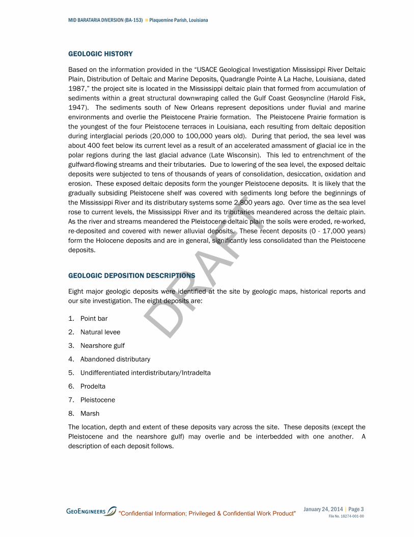
GEOLOGIC HISTORY
Based on the information provided in the “USACE Geological Investigation Mississippi River Deltaic
Plain, Distribution of Deltaic and Marine Deposits, Quadrangle Pointe A La Hache, Louisiana, dated
1987,” the project site is located in the Mississippi deltaic plain that formed from accumulation of
sediments within a great structural downwraping called the Gulf Coast Geosyncline (Harold Fisk,
1947). The sediments south of New Orleans represent depositions under fluvial and marine
environments and overlie the Pleistocene Prairie formation. The Pleistocene Prairie formation is
the youngest of the four Pleistocene terraces in Louisiana, each resulting from deltaic deposition
during interglacial periods (20,000 to 100,000 years old). During that period, the sea level was
about 400 feet below its current level as a result of an accelerated amassment of glacial ice in the
polar regions during the last glacial advance (Late Wisconsin). This led to entrenchment of the
gulfward-flowing streams and their tributaries. Due to lowering of the sea level, the exposed deltaic
deposits were subjected to tens of thousands of years of consolidation, desiccation, oxidation and
erosion. These exposed deltaic deposits form the younger Pleistocene deposits. It is likely that the
gradually subsiding Pleistocene shelf was covered with sediments long before the beginnings of
the Mississippi River and its distributary systems some 2,800 years ago. Over time as the sea level
rose to current levels, the Mississippi River and its tributaries meandered across the deltaic plain.
As the river and streams meandered the Pleistocene deltaic plain the soils were eroded, re-worked,
re-deposited and covered with newer alluvial deposits. These recent deposits (0 - 17,000 years)
form the Holocene deposits and are in general, significantly less consolidated than the Pleistocene
deposits.
GEOLOGIC DEPOSITION DESCRIPTIONS
Eight major geologic deposits were identified at the site by geologic maps, historical reports and
our site investigation. The eight deposits are:
1. Point bar
2. Natural levee
3. Nearshore gulf
4. Abandoned distributary
5. Undifferentiated interdistributary/Intradelta
6. Prodelta
7. Pleistocene
8. Marsh
The location, depth and extent of these deposits vary across the site. These deposits (except the
Pleistocene and the nearshore gulf) may overlie and be interbedded with one another. A
description of each deposit follows.
"Confidential Information; Privileged & Confidential Work Product"

DRAFT
MID BARATARIA DIVERSION (BA-153) Plaquemines Parish, Louisiana
Page 4 | January 24, 2014 | GeoEngineers, Inc.File No. 18274-001-00
Point Bar
These deposits are formed on the inside of a river bend. They consist of material that has been
eroded upstream and often consist of relatively coarse material. In the project area, these
deposits generally consist of silty sand. Point bar deposits can be distinguished from buried sand
beaches by their position in relation to the river and by the fact that beach sands are often mixed
with shell fragments. Point bar deposits rarely contain shell fragments.
Natural Levee
Natural levees are formed by the deposition of the coarse grained sediments carried in suspension
by floodwaters that over-top riverbanks. These soils tend to consist of interbedded silty sand,
sandy silt, silt and clay, generally with coarser material closer to the river and finer-grained
sediment further from the river.
Nearshore Gulf
Nearshore gulf deposits are relatively coarse grained (i.e. silty sand and sand) deposits with shell
fragments that were deposited when the area was formerly a beach type environment. These
deposits generally are found directly over the Pleistocene deposits.
Abandoned Distributary
Distributary channels are natural channels that branch from the main trunk river and help
distribute the discharge and sediment load of the main channel. As deltas advance and the river
system moves, portions of distributary channels get cut off from the main trunk river. These
abandoned distributary channels are then naturally filled over time. The composition of the fill is
typically variable and depends on many things, but will likely be different from the surrounding soil.
In the project area, the abandoned distributary deposits consist of zones of layered soft clay and
loose silty sand, silt and clayey silt.
Undifferentiated Interdistributary/Intradelta
Interdistributary deposits are typically soft clay deposits that settle in the low areas between
distributary channels of the present and past deltas.
The intradelta deposits are generally coarser materials (fine sand and silty sand) that were
deposited at the mouth of a distributary channel. Portions of these deposits were preserved as the
delta built itself seaward and they typically are interfingered with interdistributary clay deposits.
Prodelta
Prodelta deposits are soils that were deposited beyond (seaward of) the active toe of the delta.
These are generally thick beds of clay formed over a long period of time and are normally
consolidated.
Pleistocene
Pleistocene age deposits represent what was the ground surface approximately 20,000 years ago
when sea level was approximately 400 feet lower than present day levels and the shoreline was far
gulfward (south) of its present location. As sea level rose, these deposits were covered by new
"Confidential Information; Privileged & Confidential Work Product"

DRAFT
MID BARATARIA DIVERSION (BA-153) Plaquemine Parish, Louisiana
January 24, 2014 | Page 5File No. 18274-001-00
sediment deposited by the Mississippi River, and since the river gradient decreased as sea level
rose, the sediments transported by the river became finer. Typically, Pleistocene deposits at this
site are located approximately 120 to 130 feet below grade and consist of over-consolidated stiff
to very stiff clay with sand and silt lenses.
Marsh
These deposits are encountered in the west portion of the project area overlying the soft, fine
grained interdistributary/intradelta deposits. Marsh deposits typically consist of peat and organic
clay at the surface with progressively less organics with depth. These deposits have very high
moisture contents and are highly compressible.
30% DESIGN PHASE EXPLORATION PROGRAM
General
Due to the large project area (over 3 miles long), varying geologic deposits across the project area,
and to maximize efficiency of the exploration effort, a multi-phase geotechnical exploration
program is being used for the MBD project. The purpose of the explorations for the 30% design
phase was to provide general site characterization, estimate the geotechnical engineering
properties of soils in the various geologic deposits and identify areas for further exploration in the
60% design phase. The 30% design phase exploration program consisted of drilling and sampling
39 geotechnical soil borings (both 5-inch diameter and 3-inch diameter borings), 4 locations of in-
situ field vane strength testing, 19 cone penetration test (CPT) profiles, 4 locations of vibrating wire
piezometer installations (3 piezometers at each location), 12 piezometer well locations for pump
tests, 2 pump test wells, and 2 in-situ pump tests. Field Investigation Locations, Figure 3 shows
the geotechnical exploration locations completed for this phase.
Permits and Right-of-Entry
All permits required for performing the above explorations for the MBD project were obtained by
HDR. Representatives from HDR and GeoEngineers were onsite during all exploration activities to
see that permit requirements were met. HDR and GeoEngineers coordinated with the project
environmental and archeological consultants to confirm the proposed access routes between
exploration locations did not impact known culturally sensitive areas. A variance was obtained
from the USACE to work within 1,500 feet of the existing MR&T levee when the water level was
higher than elevation +11 feet as measured at the Carrolton Gauge in New Orleans, Louisiana.
Copies of the permits are provided in Appendix A.
Quality Control, Safety, and Other Plans
A project QC program was established for the field exploration phase that follows the general
guidelines of USACE “Hurricane and Storm Damage Reduction System Design Guidelines,” dated
October 2007. Field representatives completed daily field reports, drilling logs, logs of explorations
and chains of custody forms (COCs). The COCs were completed and signed by the GeoEngineers
field representative as well as the receiving laboratory’s manager or representative. Completed
daily field reports, drilling logs, logs of borings, backfill logs, COCs, job hazard assessments and
jobsite personnel rosters were reviewed and compiled into weekly reports and submitted to HDR.
"Confidential Information; Privileged & Confidential Work Product"

DRAFT
MID BARATARIA DIVERSION (BA-153) Plaquemines Parish, Louisiana
Page 6 | January 24, 2014 | GeoEngineers, Inc.File No. 18274-001-00
As an additional quality control measure, GeoEngineers created a table tracking the status of each
boring from drilling through lab testing, drafting of the boring logs, and QA/QC of the final boring
log. The laboratory testing for mini-vane tests, dry unit weight, unconfined compression,
unconsolidated undrained compression, consolidated undrained compression, sieve and
hydrometer analysis, consolidation tests, permeability tests and Atterberg limits followed the
appropriate ASTM standards. A list of ASTM standards and additional details of the QC program
are provided in Appendix B.
GeoEngineers developed a project specific safe work plan (PSSWP) for the exploration phase to
make field personnel aware of potential hazards involved and reiterate the importance of safety in
all field activities. During our site investigation activities, there were several hazards identified at
the site including cattle, alligators, snakes, mosquitos, and difficult muddy terrain.
The PSSWP (Appendix B) was reviewed and signed by all personnel prior to entering the site and a
copy of the document was onsite during the entire exploration phase.
GeoEngineers developed and followed a Best Management Practices (BMP) plan to minimize
disturbance to wetlands, control erosion and sediment transport, and maintain quality of surface
water during field investigation for this project (Appendix B).
Field Investigation
Eighty combined soil borings, CPT’s, field vanes, pump test wells and piezometers were completed
for the 30% design phase field investigation. Appendices C, D and E, describe the details of our
explorations in the Mississippi River, on land, and in the Barataria Bay marsh, respectively. The
boring designation for explorations is based on the type of exploration and the proposed structure
of the diversion complex the boring was near or on. For example, a “NL” or “SL” designation
indicates a boring completed on the proposed conveyance channel north or south levee,
respectively. A designation of “IS” indicates a boring near the proposed inlet structure (now
referred to as the diversion structure). “M” designations are for borings drilled in the Barataria Bay
marsh and “B” designations are for the borings drilled on the batture (the flood side of the MR&T
levee). “PZ” and “PT” indicate piezometers and pump tests, respectively. “R” designation includes
the borings performed in the Mississippi River. Lastly, “FV” indicates a field vane test. The suffix
on each boring also indicates what type of exploration it is. The “A” or “B” at the end of the boring
number indicates a soil boring while a “C” indicates a CPT.
Prior to starting the work, all explorations except PZ-16 and Mississippi River borings (R-1A through
R-6A) were surveyed and staked by John Chance Land Surveys, Inc. (John Chance). GeoEngineers
located the river borings on-site using a Trimble GeoExplorer GeoXT 2005 series GPS unit. The
location of PZ-16 was determined on-site and approved by HDR representative prior to drilling. The
location coordinates for PZ-16 were recorded by GeoEngineers using a Garmin-GPSmap76CSx
handheld GPS unit. GeoEngineers contacted the Louisiana “One-Call” and waited for a period of at
least 72 hours for the agencies to mark underground utilities in the area prior to performing drilling
on-site. GeoEngineers maintained valid locate tickets for the duration of field work. For soil
borings in the marsh area, a 30-foot radius magnetometer survey was also completed at each
proposed boring location to confirm no metal objects were present in the near surface.
"Confidential Information; Privileged & Confidential Work Product"

DRAFT
MID BARATARIA DIVERSION (BA-153) Plaquemine Parish, Louisiana
January 24, 2014 | Page 7File No. 18274-001-00
All explorations were completed between May 11, 2013 and November 19, 2013 using equipment
shown in Table 1. All exploration locations were approved by the HDR representative onsite prior to
drilling. Field representatives from GeoEngineers managed the drilling on a full time basis,
examined and classified the soils encountered, and prepared a log of each exploration.
For each drill rig used to collect standard penetration test (SPT) samples, the hammer energy
transfer efficiency was measured. A Pile Driving Analyzer® (PDA) system, model PAX was used to
acquire and process the dynamic test data obtained through an instrumented drill rod section. A
summary of the hammer calibration results are provided in Table 1 below. The details of the
calibration are provided in Appendix K.
TABLE 1: DRILL RIGS, CPT AND SUPPORT EQUIPMENT INFORMATION
Company Drill Rig Model Serial No.
Year
Manufactu
red Hammer Type
Hammer
Efficiency
GeoEngineers
Inc.
Truck Failing
1500
902978 1965 140lb safety
hammer w/ 2
turns of rope on
cathead
72%
GeoEngineers
Inc.
Rubber Tire
ATV
Ardco
K-1000
4682462
0
2008 Automatic
(140lb)
77%
SER1 Marsh
Buggy Track
Drill Rig
SER custom
made
MBD001 2012 140lb safety
hammer w/ 2
turns of rope on
cathead
58%
Fugro2 CME Track
Rig
CME 850 361982 2008 Automatic
(140lb)
86%
SES3 Diedrich
Track Rig
D50 268 2007 Automatic
(140lb)
85%
SES3 20 Ton CPT
Track Rig
Hogentogler 17-3 2001 N/A N/A
SES3 Geoprobe
Grout Rig
Geoprobe
6625
Z5339T6
625
2006 N/A N/A
SER1 Marsh
Master
Carrier
Marsh
Master
MM2 2010 N/A N/A
1 SER – Specialized Environmental Resources, LLC.
2 Fugro – Fugro Consultants, Inc.
3 SES – Southern Earth Sciences, Inc.
"Confidential Information; Privileged & Confidential Work Product"

DRAFT
MID BARATARIA DIVERSION (BA-153) Plaquemines Parish, Louisiana
Page 8 | January 24, 2014 | GeoEngineers, Inc.File No. 18274-001-00
A summary of the field explorations performed for the 30% design phase is given in Table 2 below:
TABLE 2: FIELD INVESTIGATION 30% DESIGN PHASE SUMMARY
Location of
Exploration Type of Exploration Mapped Surficial Geology *
Number of
Explorations
East of MR&T Levee (Sta. 0+00 to Sta. 28+00)
River 5-inch Soil Borings Point Bar 6
Batture5-inch Soil Borings Natural Levee/Point Bar 3
CPT Natural Levee/Point Bar 2
MR&T Levee (Sta. 28+00 to Sta. 32+00)
Protected Side
Toe
5-inch Soil Borings Natural Levee/Point Bar 3
CPT Natural Levee/Point Bar 3
Centerline5-inch Soil Borings Natural Levee/Point Bar 7
CPT Natural Levee/Point Bar 4
Diversion Structure/ Conveyance Complex/Storm Surge Protection Structure (Sta. 32+00 to Sta. 139+00)
East of Hwy 23
5-inch Soil BoringsNatural Levee/Point Bar / Abandoned
Distributary2
CPT Natural Levee /Abandoned Distributary 1
Field Vane Test Natural Levee /Abandoned Distributary 1
Pump Test
PiezometersNatural Levee /Point Bar 6
Pump Test Well Natural Levee /Point Bar 1
VM Piezometers Point Bar 1
Hwy 23 CPT Natural Levee /Interdistributary 1
West of Hwy 23
5-inch Soil BoringsNatural Levee/Abandoned
Distributary/Interdistributary/Marsh2
CPTNatural Levee/Abandoned
Distributary/Interdistributary/Marsh8
Field Vane TestNatural Levee/Abandoned
Distributary/Interdistributary/Marsh3
VM PiezometersNatural Levee/Abandoned
Distributary/Interdistributary/Marsh3
Pump Test
PiezometersMarsh 6
Pump Test Well Marsh 1
Back Levee (Sta. 139+00 to Sta. 140+00)
None Marsh 0
Outfall Area (Sta. 140+00 and on)
West of NOV
levee3-inch Soil Borings Marsh 16
Total Explorations 80
* Based on the information provided in the “Geological Investigation Mississippi River Deltaic Plain, Distribution of Deltaic
and Marine Deposits, Quadrangle Pointe A La Hache, Louisiana, dated 1987.”
"Confidential Information; Privileged & Confidential Work Product"

DRAFT
MID BARATARIA DIVERSION (BA-153) Plaquemine Parish, Louisiana
January 24, 2014 | Page 9File No. 18274-001-00
Existing geotechnical boring information from USACE was provided to the design team. This
included subsurface information from the USACE New Orleans to Venice, Louisiana (NOV),
Plaquemines Parish Non-Federal Levee (NOV-NF-W-06) project that had exploration information
along the back levee. The USACE had also documented 10 other borings in and around the
general project boundaries as shown on Figure 3.
LABORATORY TESTING
Soil samples obtained from the soil borings were transported to a laboratory and examined to
confirm or modify field classifications, as well as to evaluate engineering properties of the samples.
General guidelines provided by the USACE were followed for transportation, sample
extrusion/preservation and testing of soil samples. The three laboratories used for testing
samples were USACE certified.
Samples delivered to the laboratory were extruded from sampling tubes (as appropriate), tested for
moisture content, visually classified, and preserved for future testing. This was completed within
seven days of drilling and sampling. Following extrusion and visual logging of the samples in the
laboratory, the laboratory logs were reviewed by an engineer and compared to the field logs to
check field descriptions, to provide initial delineation of soil units and make initial lab assignment
recommendations. Mini-vane tests were performed on soil samples collected in the marsh prior to
extrusion. The handwritten log with the initial moisture contents was called the “Engineers’ log”.
Laboratory assignments were reviewed and approved by HDR prior to performing the tests.
Laboratory testing performed on representative samples included mini-vane tests, unit weight,
unconfined compression, unconsolidated undrained compression, consolidated undrained
compression, sieve and hydrometer analysis, consolidation, organic content, specific gravity,
permeability and Atterberg limits tests. All test results except for consolidation tests are presented
on the soil boring logs and are included in Appendices F, G and H for river, land, and marsh borings
respectively. The consolidation test results for the 30% design phase exploration have been
included in Appendix J.
A self-weight consolidation test performed on a composite sample obtained from river boring R-6A
is included in Appendix H.
LIMITATIONS
The information presented in this report is based on the soil borings and soil testing completed for
this study, and judgments made by the engineers. This report is specific to this site and should not
be used other than for the design of the Mid Barataria Diversion project (BA-153), located in Myrtle
Grove, Louisiana. We have provided the requested information for the geotechnical investigation
data report. A detailed engineering report for the marsh borings will be provided in a separate
report. HDR will be preparing a geotechnical engineering report for the overall project that will
include the information presented in this data report.
Within the limitations of scope, schedule and budget, our services have been executed in
accordance with generally accepted practices in the field of geotechnical engineering in this area
"Confidential Information; Privileged & Confidential Work Product"

DRAFT
MID BARATARIA DIVERSION (BA-153) Plaquemines Parish, Louisiana
Page 10 | January 24, 2014 | GeoEngineers, Inc.File No. 18274-001-00
at the time this report was prepared. No warranty or other conditions express or implied should
be understood.
Please refer to “Report Limitations and Guidelines for Use” for additional information pertaining to
use of this report.
TECHNICAL REFERENCES
Andres Aslan and Whitney J. Autin, Evolution of the Holocene Mississippi River Floodplain, Ferriday,
Louisiana: Insights on the Origin of Fine-Grained Floodplains, Journal of Sedimentary
Research, Vol. 69, No. 4, July 1999, P. 800-815.
Harold N. Fisk, Fine-Grained Alluvial Deposits and Their Effects on Mississippi River Activity, War
Department, Corps of Engineers, Mississippi River Commission, Vicksburg, Mississippi, July
1947.
Survey Information provided by John Chance Land Surveys, Inc. for the Mid Barataria Diversion
Project (BA-153).
U.S. Army Corps of Engineers, Geological Investigation Mississippi River Deltaic Plain, Distribution
of Deltaic and Marine Deposits, Quadrangle Pointe A La Hache, Louisiana, dated 1987.
U.S. Army Engineer Waterways Experiment Station, CE, Geology of the Mississippi River Deltaic
Plain Southeastern Louisiana, by C.R. Kolb, and J. R. Van Lopik. Technical Report No. 3-
483, July Volume 1, 1958.
U.S. Army Engineer Waterways Experiment Station, CE, Distribution of Soils Bordering the
Mississippi River From Donaldsonville to Head of Passes, by C.R. Kolb. Technical Report
No. 3-601, June 1962.
"Confidential Information; Privileged & Confidential Work Product"

Earth Science + Technology
Type Name of Services HereName of Project Here
forType Client Name Here
Type Date of Report Here
DRAFT

Miles
W E
N
Mid Barataria Diversion (BA-153) ProjectPlaquemines Parish, Louisiana
VICINITY MAP
Figure 1
Notes:1. The locations of all features shown are approximate.2. This drawing is for information purposes. It is intended to assist in showing features discussed in an attached
document. GeoEngineers, Inc. can not guarantee the accuracy and content of electronic files. The master file is storedby GeoEngineers, Inc. and will serve as the official record of this communication.
Reference: Aerial image was taken from Google Earth Pro., Licensed to GeoEngineers Inc., Imagery dated: 11/14/2012
P:\18\18274001\00\CAD\Vicinity Map.dwg\TAB:Layout1 (2) modified on Jan 16, 2014 - 5:18pm KMCVT
STATE & PARISHOUTLINE
SITESITE
BELLE CHASSE
MYRTLE GROVE
ALLIANCE
NEW ORLEANS
PORT SULPHUR
EMPIREDRAFT

Feet
S
W E
N
Mid Barataria Diversion (BA-153) ProjectPlaquemines Parish, Louisiana
SURFICIAL GEOLOGY, TOPOGRAPHY& PROJECT ELEMENTS
Figure 2
P:\1
8\18
2740
01\0
0\C
AD
\Site
Loc
atio
n P
lan
0114
14.d
wg\
TAB
:Lay
out2
mod
ified
on
Jan
17, 2
014
- 7:0
6am
KM
CD
SE
GEOLOGY LEGEND
Point Bar
Undifferentiated Interdistributary/Intradelta Deposits
Natural Levee
Abandoned DistributaryD
Land Loss (1932-1983)
Elevation of Upper Fine-GrainedPleistocene surface in feet MSL
-125
1. The locations of all features shown are approximate.Notes:
2. This drawing is for information purposes. It is intended to assist in showingfeatures discussed in an attached document. GeoEngineers, Inc. can notguarantee the accuracy and content of electronic files. The master file isstored by GeoEngineers, Inc. and will serve as the official record of thiscommunication.
Reference: 1. Geology map was taken from USACE, Alluvial Deposits Map,Quads: Barataria & PointeALaHache, Dated 19872. Aerial image was taken from Google Earth Pro., Licensed to GeoEngineers,Inc., Imagery dated: 10-29-2012
S
W E
N
3. Base file was provided by HDR Engineering, 60% Bore Plan 103013.dwg,Dated: 10/2013
Minor Contour (2' Intervals)Major Contour (10' Intervals)
4. Elevation data was taken from USGS, 1/9 arc Second, Dated 2006. Elevationsbased on survey information were provided by John Chance for soil explorationfor 30% design phase. These elevations vary from approximately +5 ft. to -5 ft.between the MR&T levee and the back levee as shown on boring logs inAppendices C through E.
Feet
TOPOGRAPHIC LEGEND
Marsh
DETAIL 1
PUMPSTATION
0'
0' 2'
2'
2'
2'
DRAFT

Feet
S
W E
N
Mid Barataria Diversion (BA-153) ProjectPlaquemines Parish, Louisiana
FIELD INVESTIGATION LOCATIONS
Figure 3
Notes:1. The locations of all features shown are approximate.2. This drawing is for information purposes. It is intended to assist in
Reference:
showing features discussed in an attached document.GeoEngineers, Inc. can not guarantee the accuracy and contentof electronic files. The master file is stored by GeoEngineers, Inc.and will serve as the official record of this communication.
Dated: 10/20131. Base file was provided by HDR Engineering, 60% Bore Plan 103013.dwg,
LEGENDM-12/PZ-1 3" Borehole Location/ Piezometer Location
NL-1C CPT LocationIS-1A 5" Borehole Location
R-60.4-R USACE Boring Location
2. Aerial image was taken from Google Earth Pro., Licensed to GeoEngineers, Inc.,Imagery dated: 10-29-2012
MARSH BORING LOCATIONS
FeetS
W E
N
DRAFT

Earth Science + Technology
Type Name of Services HereName of Project Here
forType Client Name Here
Type Date of Report Here
DRAFT


