28
GEOTECHNICAL ENGINEERING LIGHTWEIGHT SOLUTIONS WITH EXPANDED CLAY LATERLITE

GEOTECHNICAL ENGINEERINGLIGHTWEIGHT SOLUTIONS WITH EXPANDED CLAY LATERLITE

CONTENTS
Geotechnical features of Expanded Clay Laterlite 3
Road embankments and foundations 6
Bearing walls 14
Panel walls 15
Alignment ramps 16
Falling rocks 17
Drainage trench and pipe laying 18
Backfilling on structures and re-profiling of slopes 19
Re-filling of cavitiess and undersoil cavities 20
Civil and environmental lightweight filling 22
Road surfaces 24
Other road applications 25
Expanded Clay Laterlite Concrete 26
Delivery modalities 27
III editionUpdated September 2006 - © Laterlite – All rights reserved – The unauthorized reproduction, even partial, is prohibited. For any further information contact Laterlite Technical Assistance (tel. 02 48011962).

3
GEOTECHNICAL FEATURES
Exclay granule: the air-filled cavities of thematerial forming the granule are closed insi-de a hard and resistant shell.
The specific weight of expanded clay inpiles is about 1/4 of the weight of a tradi-tional inert quarry material.
Exclay in piles.
* Note: the Specific Weight (γ) expressed in Kgpeso/m3 is given by the product of the Mass (ρ)expressed in Kgmassa/m3 pdue to gravity acceleration (g). Since in practice both are used indiffe-rently Kgpeso and Kgmassa, the two sizes shall be considered numerically the same in this docu-ment.
Exclay is a porous inert substance with a limited specific weight. The greatquantity of air-filled cavities inside the material determines the creation of twodifferent types of cavities: inter-granules (between granules) and intra-granu-les (inside the granules).While the first are interconnected and easily saturated when the material isplaces under stratum, the intra-granule cavities don’t fill up with water soeasily and some of them will never fill up.
Let’s analyze the main features:
1) SPECIFIC WEIGHTS*We define: γass = absolute specific weight
The weight a cubic meter of Exclay would have without the cavities betweengranules (inter-granular) and the cavities contained in each granule (intra-granular);
γapp = apparent specific weight (or average specific weight of granules);
The weight a cubic meter of Exclay would have without the cavities betweengranules (inter-granular);
γm = specific weight of material in piles
The weight of a cubic meter of Exclay not vibrated and not compressed inany way.
Material Expanded Clay Laterlite Sand(0-30) (kg/m3) (kg/m3)
Absolute specific weight ≤ 2,500 ~ 2,600Apparent specific weigh ≤ 850 ~ 2,600Specific weight of material in piles ≤ 450 ~ 1,600
COMPARATIVE TABLE OF SPECIFIC WEIGHTS: EXPANDED CLAY LATERLITE AND SAND
4
GEOTECHNICAL FEATURES
3) SOAKING The soaking test (according to UNI EN 13055-2 par. 4.8) consists in soakinga dried and weighed Exclay sample in water for a specific period of time(30’, 24h, 90 days). After it has dripped it is weighed again. The differencebetween the two weights is the quantity of water absorbed. When Exclay is immersed in water, the inter-granule cavities fill up rapidly,whereas the intra-granule cavities which are often clogged and not inter-connected, fill up slowly. The table shows the trend in time of the soakingcoefficient (ratio of the weight of water absorbed and the weight of dryExclay).
Note: during the project we suggest using a soaking coefficient of 75% ofthe specific weight of the material in piles.
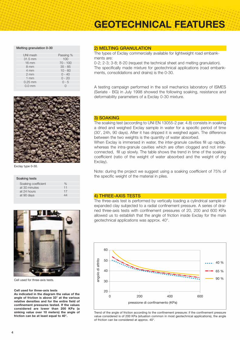
4) THREE-AXIS TESTSThe three-axis test is performed by vertically loading a cylindrical sample ofexpanded clay subjected to a radial confinement pressure. A series of drai-ned three-axis tests with confinement pressures of 20, 200 and 600 KPaallowed us to establish that the angle of friction inside Exclay for the maingeotechnical applications was approx. 40°.
A testing campaign performed in the soil mechanics laboratory of ISMES(Seriate - BG) in July 1998 showed the following soaking, resistance anddeformability parameters of a Exclay 0-30 mixture.
0 200 400
30
40
50
60
20
an
go
lo d
i att
rito
pressione di confinamento (KPa)
600
40 %
65 %
90 %
UNI mesh Passing %31.5 mm 10016 mm 70 - 1008 mm 35 - 854 mm 10 - 602 mm 0 - 401 mm 0 - 20
0.25 mm 0 - 50.0 mm 0
Melting granulation 0-30
Soaking coefficient %at 30 minutes 11at 24 hours 17at 90 days 44
Soaking tests
Trend of the angle of friction according to the confinement pressure: if the confinement pressurevalue considered is of 200 KPa (situation common in most geotechnical applications), the angleof friction can be considered at approx. 40°.
Exclay type 0-30.
Cell used for three-axis tests.
Cell used for three-axis tests As indicated in the diagram the value of theangle of friction is above 33° at the variousrelative densities and for the entire field ofconfinement pressures tested. If the valuesconsidered are lower than 200 KPa (asinking value over 10 meters) the angle offriction can be at least equal to 40°.
2) MELTING GRANULATION The types of Exclay commercially available for lightweight road embank-ments are: 0-2; 2-3; 3-8; 8-20 (request the technical sheet and melting granulation).The specifically made mixture for geotechnical applications (road embank-ments, consolidations and drains) is the 0-30.
5
40% 60% 80%
50
150
250
300
0
Md
(10
2 k
N/m
2)
Dr
90%50% 70%
200
100
100%
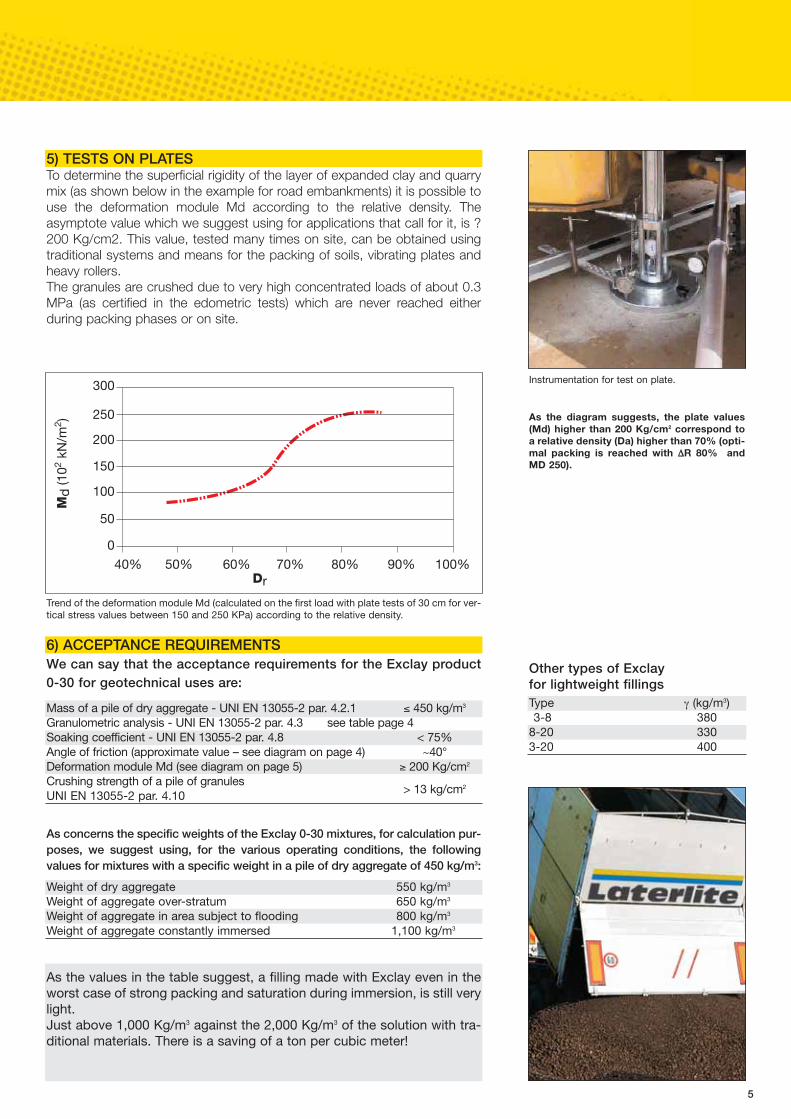
Trend of the deformation module Md (calculated on the first load with plate tests of 30 cm for ver-tical stress values between 150 and 250 KPa) according to the relative density.
6) ACCEPTANCE REQUIREMENTSWe can say that the acceptance requirements for the Exclay product0-30 for geotechnical uses are:
As concerns the specific weights of the Exclay 0-30 mixtures, for calculation pur-poses, we suggest using, for the various operating conditions, the followingvalues for mixtures with a specific weight in a pile of dry aggregate of 450 kg/m3:
5) TESTS ON PLATESTo determine the superficial rigidity of the layer of expanded clay and quarrymix (as shown below in the example for road embankments) it is possible touse the deformation module Md according to the relative density. Theasymptote value which we suggest using for applications that call for it, is ?200 Kg/cm2. This value, tested many times on site, can be obtained usingtraditional systems and means for the packing of soils, vibrating plates andheavy rollers. The granules are crushed due to very high concentrated loads of about 0.3MPa (as certified in the edometric tests) which are never reached eitherduring packing phases or on site.
As the values in the table suggest, a filling made with Exclay even in theworst case of strong packing and saturation during immersion, is still verylight.Just above 1,000 Kg/m3 against the 2,000 Kg/m3 of the solution with tra-ditional materials. There is a saving of a ton per cubic meter!
Instrumentation for test on plate.
As the diagram suggests, the plate values(Md) higher than 200 Kg/cm2 correspond toa relative density (Da) higher than 70% (opti-mal packing is reached with ΔR 80% andMD 250).
Mass of a pile of dry aggregate - UNI EN 13055-2 par. 4.2.1 ≤ 450 kg/m3
Granulometric analysis - UNI EN 13055-2 par. 4.3 see table page 4Soaking coefficient - UNI EN 13055-2 par. 4.8 < 75%Angle of friction (approximate value – see diagram on page 4) ~40°Deformation module Md (see diagram on page 5) ≥ 200 Kg/cm2
Crushing strength of a pile of granules UNI EN 13055-2 par. 4.10 > 13 kg/cm2
Weight of dry aggregate 550 kg/m3
Weight of aggregate over-stratum 650 kg/m3
Weight of aggregate in area subject to flooding 800 kg/m3
Weight of aggregate constantly immersed 1,100 kg/m3
Other types of Exclay for lightweight fillingsType γ (kg/m3)3-8 380
8-20 3303-20 400

6
LIGHT ROAD EMBANKMENTS
The planning of new road embankments or the expansion of existing roadembankments, located on soils with poor mechanical properties, is general-ly very difficult. They are often damaged and the costs to prevent damage tothe roads are very high. Thanks to Exclay the costs for stabilizing the basesoil can be avoided totally or in part. In fact by exploiting the incrediblereduction of the weight of the road embankment it is possible to carry outseveral interventions using the load compensation technique. This techniqueenables to build the road embankment without increasing (or just slightlyincreasing) the loads on the soil, thus keeping the original stretch balanceunchanged. Various systems are available to contain the road embankment as shown inthe figure below.For over 30 years now Exclay has been used the world over to create roadembankments on freezable or soft soils.
ADVANTAGESIThe main advantages of a compensated load solution are:• At the end of the process and the packing, the light Exclay road embank-
ment significantly reduces the absolute and differential sinking. • The use of Exclay considerably increases the safety coefficient calculated
with reference to the final limit of the road embankment. • The compensated load solution for logistic-technological reasons, is often
the only possible one. In fact often pre-loads are not necessary in mostcases.
• Thanks to Exclay longer and expensive construction techniques are oftenuseless.
Road embankment created on a soil withpoor carrying capacity consolidated throughpiling.
Road embankment created with Exclay usingthe load compensation technique on a soilwith poor carrying capacity (without usingpre-loads or piling).
Pre-loading phase before the construction ofthe road embankment, made using verticaldrains and quarry mix.
Types of containment of a road embankment: the figure shows the most usedsystems for the containment of a road embankment with the relating “overalldimensions of the angles” (just an indication). First start from the Reinforced Soil (90°) with minimum bulk, up to the non-contai-ned material (with dimension according to the angle of natural decline, typical ofthe material).Excellent results from a technical and construction standpoint have been reachedespecially with the Reinforced Soil system and the soils reinforced with geo-claysand geo-synthetics.The latter, as a solution without containment, must be covered with a superficiallayer of quarry mix (at least 40 cm) to protect against erosions and then coveredwith soil for planting grass and plants.
7
CONTROLS AGAINST SINKINGIf we take into consideration a non-compensated road embankment createdon a layer saturated with sinking clay, not very resistant, with limited thicknessand set on a resistant sub-stratum, two possible break mechanisms couldoccur: • final condition for the extrusion of the foundation soil (E); • final condition for global break of the road embankment-foundation system
(F). A simplified analysis carried out comparing the lighter Exclay solution with aroad embankment made with a traditional quarry inert material highlightedthat: • the most probable break, in both cases, is associated to non-drainage
conditions and to a break for extrusion of the foundation soil;• in all the cases considered, the use of Exclay enables to increase the safety
coefficient by approx. 20%.
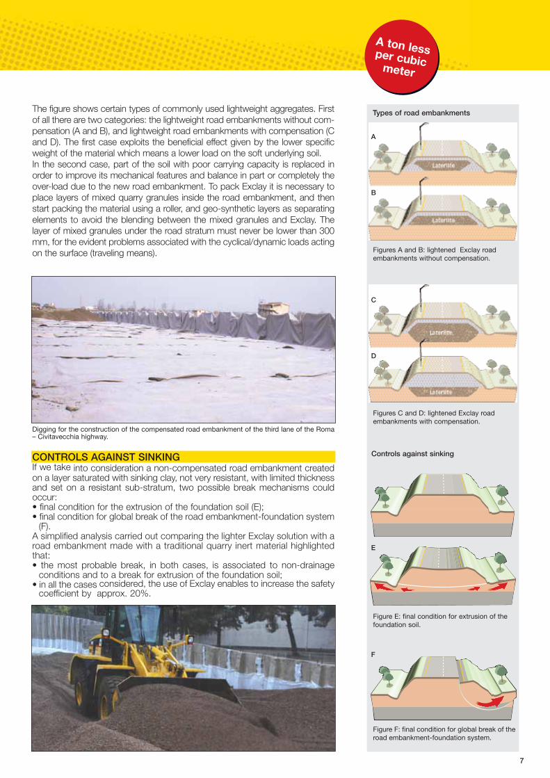
Figures A and B: lightened Exclay roadembankments without compensation.
Controls against sinking
Types of road embankments
B
A
Figures C and D: lightened Exclay roadembankments with compensation.
D
C
Figure E: final condition for extrusion of thefoundation soil.
Figure F: final condition for global break of theroad embankment-foundation system.
Digging for the construction of the compensated road embankment of the third lane of the Roma– Civitavecchia highway.
The figure shows certain types of commonly used lightweight aggregates. Firstof all there are two categories: the lightweight road embankments without com-pensation (A and B), and lightweight road embankments with compensation (Cand D). The first case exploits the beneficial effect given by the lower specificweight of the material which means a lower load on the soft underlying soil.In the second case, part of the soil with poor carrying capacity is replaced inorder to improve its mechanical features and balance in part or completely theover-load due to the new road embankment. To pack Exclay it is necessary toplace layers of mixed quarry granules inside the road embankment, and thenstart packing the material using a roller, and geo-synthetic layers as separatingelements to avoid the blending between the mixed granules and Exclay. Thelayer of mixed granules under the road stratum must never be lower than 300mm, for the evident problems associated with the cyclical/dynamic loads actingon the surface (traveling means).
E
F
A ton lessper cubicmeter
8
ROAD EMBANKMENTS ON SLOPES
The problems linked to making roads lighter becomes even more importantin the applications on slopes with risk of landslide. The reopening or con-struction of roads on soils subject to active or potential sliding often call forroad embankments made using Exclay besides reinforcement structures (asfor example walls on pies). The lightness of the material combined with itsstatic functionality (control of internal stability) means the slope can be relie-ved from the excess loads and hence prevent the sparking off or re-activa-tion of gravitational movements. The analysis of the problems of the interac-tion between slope and road embankment is very complex because it revol-ves around the study of stability and durability of the work. Or course, sincethe work consists basically in making it lighter, the opportunity of using lightmaterials according to the location of the construction on the geometric pro-file of the slope must be correctly assessed. Basically, this type of interven-tion is not recommended by the foot of the slope.
EXECUTION MODALITYThe construction modalities of a light road embankment on a slope are thesame mentioned on page 11 for road embankments on soils with poorcarrying capacity. Hence, layers of Exclay and stabilized mix will be laid onsite and the rolled flat. The anti-contaminating geo-textile put in-between canbe combined with reinforcement geo-grids (according to the project sec-tions) if a reinforced soil solution is foreseen. In the other cases the non-woven geo-textile, that no longer has a structural purpose, shall be used toprevent the fine parts from sliding into the underlying Exclay. Particularly interesting, especially for the crest expansion, is the interventionin reinforced soils with geo-grids that besides assuring the stability of thework, allow for the total cultivation of the soil, hence perfect integration in thesurrounding environment.
Underground filling in “Reinforced Exclay” -Genoa
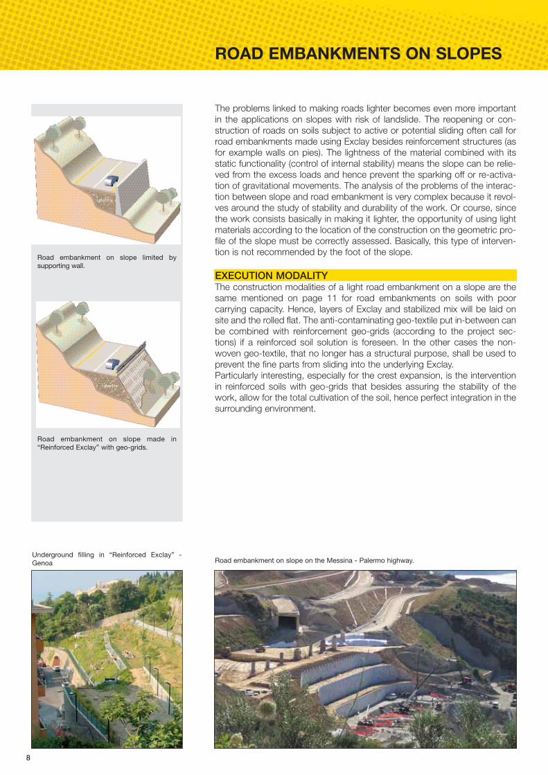
Road embankment on slope made in“Reinforced Exclay” with geo-grids.
Road embankment on slope limited by supporting wall.
Road embankment on slope on the Messina - Palermo highway.
9
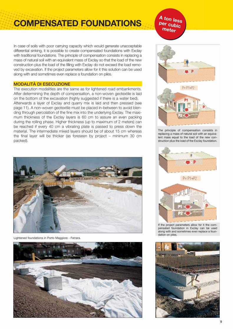
COMPENSATED FOUNDATIONS
Lightened foundations in Porto Maggiore - Ferrara.
The principle of compensation consists inreplacing a mass of natural soil with an equiva-lent mass equal to the load of the new con-struction plus the load of the Exclay foundation.
If the project parameters allow for it the com-pensated foundation in Exclay can be usedalong with and sometimes even replace a foun-dation on piles.
In case of soils with poor carrying capacity which would generate unacceptabledifferential sinking, it is possible to create compensated foundations with Exclaywith traditional foundations. The principle of compensation consists in replacing amass of natural soil with an equivalent mass of Exclay so that the load of the newconstruction plus the load of the filling with Exclay do not exceed the load remo-ved by excavation. If the project parameters allow for it this solution can be usedalong with and sometimes even replace a foundation on piles.
MODALITÀ DI ESECUZIONEThe execution modalities are the same as for lightened road embankments.After determining the depth of compensation, a non-woven geotextile is laidon the bottom of the excavation (highly suggested if there is a water bed).Afterwards a layer of Exclay and quarry mix is laid and then pressed (seepage 11). A non-woven geotextile must be placed in-between to avoid blen-ding through percolation of the fine mix into the underlying Exclay. The maxi-mum thickness of the Exclay layers is 60 cm to assure an even packingduring the rolling phase. Higher thickness (up to maximum of 2 meters) canbe reached if every 40 cm a vibrating plate is passed to press down thematerial. The intermediate mixed layers should be of about 15 cm whereasthe final layer will be thicker (as foreseen by project – minimum 30 cmpacked).
A ton lessper cubicmeter

Work sequence • general excavations; • laying of non-woven geotextile; • laying of first layer of expanded clay; • laying of non-woven geotextile; • laying and alignment of the first layer of granular quarry mix; • packing; • controls; • laying of second layer of expanded clay; • laying of non-woven geotextile; • laying and alignment of the
second layer of granular quarry mix;
• packing; • controls; • …(repeat according to height of road embankment)… • lthe final layer of quarry mix must be no thinner than 300 mm(suggested value 400 mm).
10
EXECUTION MODALITY AND PREPAR
PREPARATION OF LAYING SURFACE After completing the excavation, it is necessary to lay a non-woven geotex-tile on the bottom of the excavation as an anti-contamination separatorbetween the natural soil and the filling material. The laying surface must beregular, with the non-woven geotextile well-pulled and adherent to the surfa-ce and with integral sheets and regularly overlapping. Then filling materialscan be set in.
HOW TO LAY In general Exclay is laid in various layers, with in-between a layer of mixedgranular, whose thickness after packing should not be less than 200 mm.The thickness of the Exclay layers varies in relation to the type of section(approx. 60 - 80 cm). If in particular cases it is impossible to create layers ofExclay lower than 80 cm, it is possible to increase the thickness by doing asfollows. Maximum every 50 cm, it is necessary to pack the material using thevibrating plate up to a maximum thickness of 2 meters. This intermediateprocess shall be completed using a static and dynamic roller.The first layer of Exclay will be set by pushing the excess material forwardwith a tracked vehicle. The vehicles will unload the Exclay on site or in nearbyareas specifically prepared. Especially in the wider lanes the non-woven geotextile can be laid only alongthe sides. The central part of the lane, which is protected by the bituminouslayer, is not affected by mixing through percolation of the mix from the upperlayers into the underlying Exclay. The intermediate layer of granular mix will be set with the same modalitiesdescribed above for Exclay unloading them from the vehicles on site or innearby areas and then pushed with the proper means to form the layer of therequired thickness. Exclay will then be packed by crushing the layers of granular mix usingsmooth drum rollers both vibrating and non-vibrating, with weight and fre-quency to be defined according to the height of the layer.Bear in mind that the correct packing of Exclay corresponds to a volumetricdrop of about 17% (against 25% of traditional quarry mix).
Highway junction, Mandelieu (France).

11
RATION OF LAYING SURFACE
Laying of non-woven geotextile against soil.
View of layers from filed line.
Alignment of quarry mix with grader.Laying of non-woven getotextile over Exclay.
Unloading of expanded clay.
View of finished work.
Excavation of existing soil.
Packing of first layer and laying of second.
Laying of first layer of Exclay.
1 2 3
4
7 8 9
5 6
Roma-Civitavecchia highwayA light road embankment was created on this highway (from Km 0.300 to Km 2.500) using approx.100,000 m3 of Exclay.The intervention was done on both the North and South lane by the Company Pavimental, and after about 15 years of use it has not shown any sign ofsignificant sinking.
A ton lessper cubicmeter
12
REFERECES
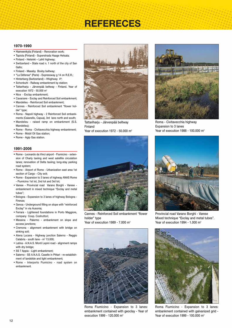
Tattariharju - Järvenpää beltwayFinlandYear of execution 1972 - 50.000 m3
Roma Fiumicino - Expansion to 3 lanes:embankment contained with geoclay - Year ofexecution 1999 - 120.000 m3
Provincial road Varano Borghi - VareseMixed technique “Exclay and metal tubes”.Year of execution 1994 - 1.000 m3
Cannes - Reinforced Soil embankment “flowerholder” typeYear of execution 1989 - 7.000 m3
Roma Fiumicino - Expansion to 3 lanes:embankment contained with galvanized grid -Year of execution 1999 - 100.000 m3
Roma - Civitavecchia highwayExpansion to 3 lanes Year of execution 1988 - 100.000 m3
1970-1990• Hameenkyla (Finland) – Renovation work; • Tapiola (Finland) - Superstrada Haage Hetsala; • Finland - Helsinki – Lahti highway; • Switzerland – State road n. 1 north of the city of San
Gallo; • Finland - Massby Boxby beltway; • "La Défense" (Paris) - Expressway g 14 on R.E.R.; • Hinterberg (Switzerland) – Hhighway 4ª; • Schonbuhl - Railway embankment by station;• Tattariharju - Järvenpää beltway - Finland. Year of
execution 1972 - 50.000 m3
• Nice - Exclay embankment; • Cavarzere - Exclay and Reinforced Soil embankment; • Mandelieu - Reinforced Soil embankment; • Cannes - Reinforced Soil embankment “flower hol-
der” type; • Roma - Napoli highway - 2 Reinforced Soil embank-
ments (Caianello, Capua), 3rd lane north and south; • Mandelieu - raised ramp on embankment (S.S.
Mandelieu); • Rome - Roma - Civitavecchia highway embankment; • Rome - Mobil Oil Gas station; • Rome - Agip Gas station.
1991-2006 • Rome - Leonardo da Vinci airport - Fiumicino - exten-
sion of Charly taxiing and west satellite circulationlanes; renovation of Delta taxiing; long-stay parkingroad system;
• Rome - Airport of Rome - Urbanization east area 1stsection of Cargo - City exit;
• Rome - Expansion to 3 lanes of highway ANAS Rome- Fiumicino 1st lot, 2nd lot and 3rd lot;
• Varese - Provincial road Varano Borghi - Varese -embankment in mixed technique “Exclay and metaltubes”;
• Bologna - Expansion to 3 lanes of highway Bologna -Firenze;
• Genoa - Underground filling on slope with “reinforcedExclay” in via Ausonia;
• Ferrara - Lightened foundations in Porto Maggiore,company Coop. Costruttori;
• Messina - Palermo - embankment on slope andaccess junctions;
• Cremona - alignment embankment with bridge onsinking soil;
• Atena Lucana - Highway junction Salerno - ReggioCalabria - south lane - m3 13.000;
• Latina - A.N.A.S. Monti Lepini road - alignment rampswith dry bridge;
• SS 7 Appia - Light embankment;• Salerno - SS A.N.A.S. Caselle in Pittari - re-establish-
ment of landslide and light embankment;• Rome - Interporto Fiumicino - road system on
embankment.

13
Mandelieu - Reinforced Soil embankment Year of execution 1990- 12,000 m3
Mandelieu - Reinforced Soil embankment Year of execution 1991- 12.000 m3
3 lane highway Nice - Aix en Provence Year of execution 1991 - 7,000 m3
Cremona - Alignment embankment with bridgeon sinking soilYear of execution 2002 - 3,000 m3
Airport Fiumicino - Rome Long-stay parking road systemYear of execution 1996 - 25,000 m3
SS 7 AppiaLight embankment (Company Della Nova) Year of execution 2005 - 9,000 m3
Salerno - SS A.n.a.s. Caselle in PittariRe-establishment of landslide and light embankment(Comp. Vangone) - Year of execution 2005 - 4,800 m3
Autostrada Messina - Palermo highwayEmbankment on slope (Company INC) Year of execution 2003 - 7,000 m3
Cavarzere - road junction Year of execution 1991 - 4,500 m3
A ton lessper cubicmeter

14
SUPPORTING WALLS
When a gravity supporting wall is created to stabilize an excavation, a natu-ral or artificial slope, it is necessary to remove a part of soil upstream.In certain cases it may be convenient to replace this soil with Exclay, and notwith a traditional quarry inert mix, to assure lightness, limited bulk and redu-ce deformations.Bear in mind that it is necessary to use a granular material for the upstreamre-filling of a supporting wall. Soils with poor drainage properties could causewater retention problems and hence a pressure build-up.Particularly interesting is the use of Exclay for re-filling behind supportingwalls that are run-down, damaged or not designed correctly. In all thesecases intervening with a light draining material that is easy to lay may avoidhaving to replace the wall yet keeping the safety coefficients high. Also in thecase of supporting walls that must be suitable for the contingent geo-morphological situation through an increase in height, it may be useful topump in expanded clay without excessive waste of labor.
ADVANTAGESUsing Exclay means: • reducing the load of the refilling; • reducing the push that the upstream soil exercises on the wall; • reducing the size of the wall used as stabilizing structure; • assuring constant drainage (approx. 30% of cavities).
Refilling with Exclay reduces the push on thesupporting wall.
The easy-to-supply pumping method helps limit the costs of labor.

15
PANEL WALLS
Panel walls are prefabricated structures or structures cast on site that areused to support artificial excavations, either temporary and/or permanent,preventing the soil to flow into the excavation.In certain particular cases, as in the creation of port structures and infra-structures and artificial islands, the soil that gives the unbalancing pushagainst the supporting structure is deposited artificiallyIn these cases the use of Exclay enables the use of shelf panel walls with alimited driving depth (D) despite the height of the wall itself (H), hence a higherH/D ratio (see figure).
ADVANTAGESThe design of a panel wall is based on the calculation of the pushes thattends to make it rotate around a hypothetical point of instant rotation. Byreducing the unbalancing push (active push) it is possible, all other valuesbeing equal, to reduce the driving depth (hence the portion of soil that crea-tes the counter-push – passive push) thus allowing the designer to use shor-ter panel walls. As regards tensioning walls, using Exclay in certain cases may avoid resor-ting to this type of solution thus avoiding the complex and expensive workfor the creation of anchoring bolts.
Creation of panel walls with Exclay filling reduces the driving depth D (hence the H/D ratio increases).
If the filling soil is Exclay, thanks to its featu-res of lightness, the active thrust drops to1/4.
Diagrams of pushes
Port structure created through filling panelwalls with Exclay.
Belgium: constructions with Exclay panelwalls.

16
In the construction of access ramps to dry bridges, road junctions orembankments aligned with structures, one of the inconveniences that morefrequently occur is the formation of differences in height between the quotesof the “rigid structures” (generally made of cement) and those of the fillingsnormally done with dry material coming from quarries. One of the phenome-na, often cause of these inconveniences, is the progressive settling due tothe cyclical loads of the inconsistent materials forming the embankment,compounded by the percolation of waters and the consequent variation ofthe humidity of the mass. The inert quarry mix which is generally used has avariable packing ratio (24-28%) according to the granulation, shape, layinghumidity and loads it is subjected to during the packing process.
ADVANTAGES Exclay has variable packing ratios according to the melting granulation andthe specific weight foreseen in the project, without ever reaching the valuesof a traditional quarry mix (approx. -20%).The packing process, even if it is carried out with standard construction sitevehicles, gives the Exclay mixture a very high rigidity thus reducing, thanks tothe low specific weight, the inconveniences due to settling of the original soilof the foundation. To prevent packing defects, especially near the shoulder, it is necessary tocarry out the packing operations with easy-to-handle machines as for exam-ple vibrating plates type 40x70 cm (weight ≥ 70 Kg) and on Exclay layerslower than 50 cm. If there is a risk of poor packing even with light equipmentwe suggest mixing the expanded clay with cement to obtain a mixture withhigh rigidity levels, thus limiting the risk of sinking.
Using packed Exclay to build alignmentramps gives the system high rigidity thusreducing the inconveniences due to differen-tial settling.
Construction of an alignment ramp with a bridge over a railway (Roma – Fiumicino highway).
Construction of a light ramp in Cavarzere (VE).
ALIGNMENT RAMPS AND STRUCTURES
17
FALLING ROCKS
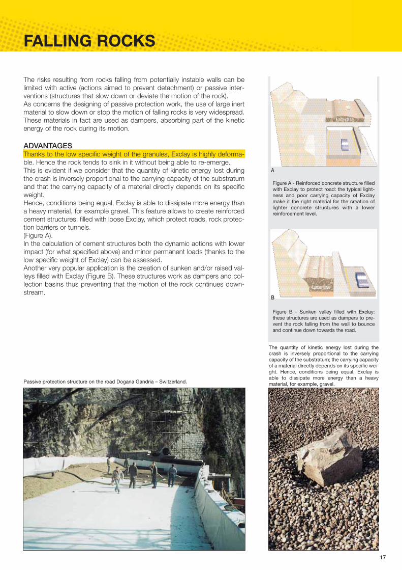
The risks resulting from rocks falling from potentially instable walls can belimited with active (actions aimed to prevent detachment) or passive inter-ventions (structures that slow down or deviate the motion of the rock).As concerns the designing of passive protection work, the use of large inertmaterial to slow down or stop the motion of falling rocks is very widespread.These materials in fact are used as dampers, absorbing part of the kineticenergy of the rock during its motion.
ADVANTAGES Thanks to the low specific weight of the granules, Exclay is highly deforma-ble. Hence the rock tends to sink in it without being able to re-emerge. This is evident if we consider that the quantity of kinetic energy lost duringthe crash is inversely proportional to the carrying capacity of the substratumand that the carrying capacity of a material directly depends on its specificweight. Hence, conditions being equal, Exclay is able to dissipate more energy thana heavy material, for example gravel. This feature allows to create reinforcedcement structures, filled with loose Exclay, which protect roads, rock protec-tion barriers or tunnels. (Figure A).In the calculation of cement structures both the dynamic actions with lowerimpact (for what specified above) and minor permanent loads (thanks to thelow specific weight of Exclay) can be assessed.Another very popular application is the creation of sunken and/or raised val-leys filled with Exclay (Figure B). These structures work as dampers and col-lection basins thus preventing that the motion of the rock continues down-stream.
A
Figure A - Reinforced concrete structure filledwith Exclay to protect road: the typical light-ness and poor carrying capacity of Exclaymake it the right material for the creation oflighter concrete structures with a lowerreinforcement level.
Figure B - Sunken valley filled with Exclay:these structures are used as dampers to pre-vent the rock falling from the wall to bounceand continue down towards the road.
B
Passive protection structure on the road Dogana Gandria – Switzerland.
The quantity of kinetic energy lost during thecrash is inversely proportional to the carryingcapacity of the substratum; the carrying capacityof a material directly depends on its specific wei-ght. Hence, conditions being equal, Exclay isable to dissipate more energy than a heavymaterial, for example, gravel.
18
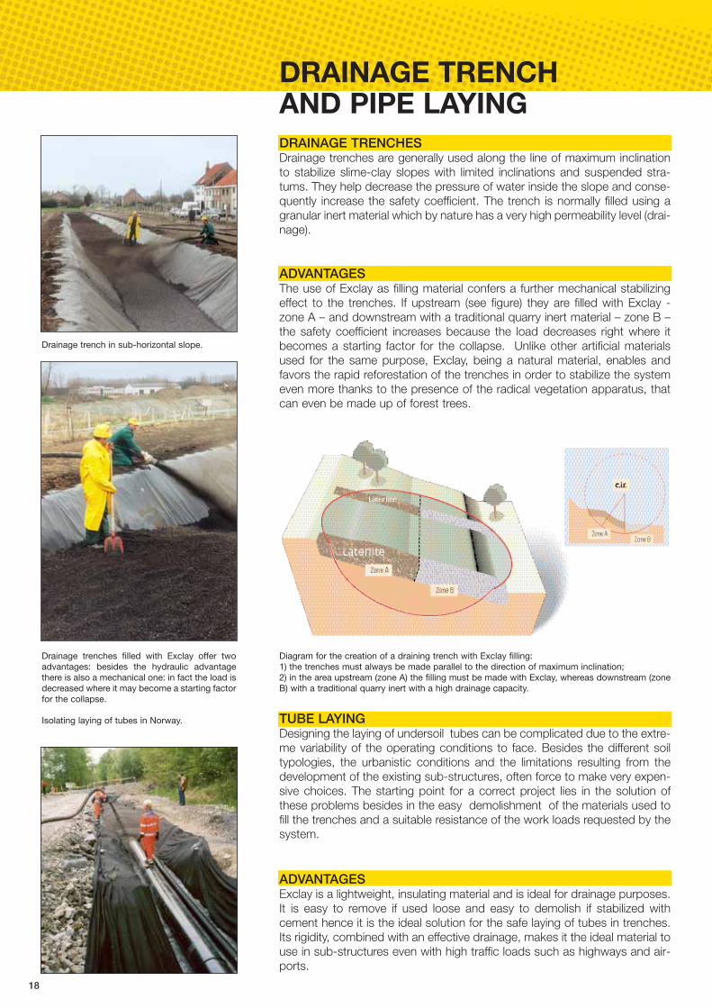
DRAINAGE TRENCH AND PIPE LAYINGDRAINAGE TRENCHESDrainage trenches are generally used along the line of maximum inclinationto stabilize slime-clay slopes with limited inclinations and suspended stra-tums. They help decrease the pressure of water inside the slope and conse-quently increase the safety coefficient. The trench is normally filled using agranular inert material which by nature has a very high permeability level (drai-nage).
ADVANTAGESThe use of Exclay as filling material confers a further mechanical stabilizingeffect to the trenches. If upstream (see figure) they are filled with Exclay -zone A – and downstream with a traditional quarry inert material – zone B –the safety coefficient increases because the load decreases right where itbecomes a starting factor for the collapse. Unlike other artificial materialsused for the same purpose, Exclay, being a natural material, enables andfavors the rapid reforestation of the trenches in order to stabilize the systemeven more thanks to the presence of the radical vegetation apparatus, thatcan even be made up of forest trees.
TUBE LAYINGDesigning the laying of undersoil tubes can be complicated due to the extre-me variability of the operating conditions to face. Besides the different soiltypologies, the urbanistic conditions and the limitations resulting from thedevelopment of the existing sub-structures, often force to make very expen-sive choices. The starting point for a correct project lies in the solution ofthese problems besides in the easy demolishment of the materials used tofill the trenches and a suitable resistance of the work loads requested by thesystem.
ADVANTAGESExclay is a lightweight, insulating material and is ideal for drainage purposes.It is easy to remove if used loose and easy to demolish if stabilized withcement hence it is the ideal solution for the safe laying of tubes in trenches.Its rigidity, combined with an effective drainage, makes it the ideal material touse in sub-structures even with high traffic loads such as highways and air-ports.
Isolating laying of tubes in Norway.
Drainage trench in sub-horizontal slope.
Drainage trenches filled with Exclay offer twoadvantages: besides the hydraulic advantagethere is also a mechanical one: in fact the load isdecreased where it may become a starting factorfor the collapse.
Diagram for the creation of a draining trench with Exclay filling: 1) the trenches must always be made parallel to the direction of maximum inclination;2) in the area upstream (zone A) the filling must be made with Exclay, whereas downstream (zoneB) with a traditional quarry inert with a high drainage capacity.
19
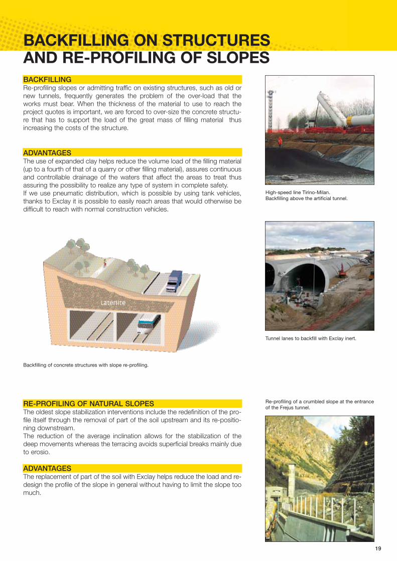
BACKFILLING ON STRUCTURES AND RE-PROFILING OF SLOPES
RE-PROFILING OF NATURAL SLOPESThe oldest slope stabilization interventions include the redefinition of the pro-file itself through the removal of part of the soil upstream and its re-positio-ning downstream. The reduction of the average inclination allows for the stabilization of thedeep movements whereas the terracing avoids superficial breaks mainly dueto erosio.
ADVANTAGESThe replacement of part of the soil with Exclay helps reduce the load and re-design the profile of the slope in general without having to limit the slope toomuch.
Re-profiling of a crumbled slope at the entranceof the Frejus tunnel.
High-speed line Tirino-Milan. Backfilling above the artificial tunnel.
Tunnel lanes to backfill with Exclay inert.
Backfilling of concrete structures with slope re-profiling.
BACKFILLINGRe-profiling slopes or admitting traffic on existing structures, such as old ornew tunnels, frequently generates the problem of the over-load that theworks must bear. When the thickness of the material to use to reach theproject quotes is important, we are forced to over-size the concrete structu-re that has to support the load of the great mass of filling material thusincreasing the costs of the structure.
ADVANTAGESThe use of expanded clay helps reduce the volume load of the filling material(up to a fourth of that of a quarry or other filling material), assures continuousand controllable drainage of the waters that affect the areas to treat thusassuring the possibility to realize any type of system in complete safety. If we use pneumatic distribution, which is possible by using tank vehicles,thanks to Exclay it is possible to easily reach areas that would otherwise bedifficult to reach with normal construction vehicles.
20
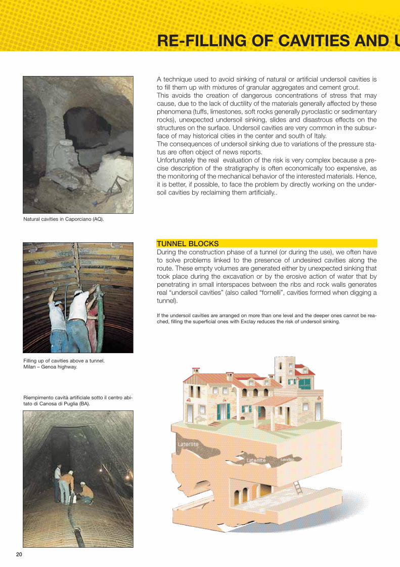
RE-FILLING OF CAVITIES AND U
A technique used to avoid sinking of natural or artificial undersoil cavities isto fill them up with mixtures of granular aggregates and cement grout.This avoids the creation of dangerous concentrations of stress that maycause, due to the lack of ductility of the materials generally affected by thesephenomena (tuffs, limestones, soft rocks generally pyroclastic or sedimentaryrocks), unexpected undersoil sinking, slides and disastrous effects on thestructures on the surface. Undersoil cavities are very common in the subsur-face of may historical cities in the center and south of Italy. The consequences of undersoil sinking due to variations of the pressure sta-tus are often object of news reports. Unfortunately the real evaluation of the risk is very complex because a pre-cise description of the stratigraphy is often economically too expensive, asthe monitoring of the mechanical behavior of the interested materials. Hence,it is better, if possible, to face the problem by directly working on the under-soil cavities by reclaiming them artificially..
TUNNEL BLOCKS During the construction phase of a tunnel (or during the use), we often haveto solve problems linked to the presence of undesired cavities along theroute. These empty volumes are generated either by unexpected sinking thattook place during the excavation or by the erosive action of water that bypenetrating in small interspaces between the ribs and rock walls generatesreal “undersoil cavities” (also called “fornelli”, cavities formed when digging atunnel).
Filling up of cavities above a tunnel. Milan – Genoa highway.
Riempimento cavità artificiale sotto il centro abi-tato di Canosa di Puglia (BA).
Natural cavities in Caporciano (AQ).
If the undersoil cavities are arranged on more than one level and the deeper ones cannot be rea-ched, filling the superficial ones with Exclay reduces the risk of undersoil sinking.

21
UNDERSOIL CAVITIES
ADVANTAGESFilling undersoil cavities with granular aggregates mostly aims to reestablishthe situation as it once was in the subsurface. The empty space that’s beencreated in fact generates dangerous stress of pure traction along the verticalaxis and of pure compression along the horizontal one. Using Exclay (mixed with cement), thanks to its high resistance to compres-sion, helps avoid the concentration of the stress that in the meantime disap-pears (traction stress) or moves to wider areas (compression stress). The advantage of using Exclay is even more evident if there is a system ofoverlapping cavities, some of which might even be difficult to reach. The fea-tures of lightness and resistance make Exclay the safest solution in thesecases. In the light of restoring the original environmental conditions, the fact thatExclay is a natural product with effective drainage is a very important featu-re. Besides the benefits of static and hydraulic nature, Exclay assures anincredible technological advantage: both Exclay and the cement can bepumped in the cavities separately or mixed (see photo on side and “ExclayPPC” technology on page 27).
In 2002 a research was carried out with the University La Sapienza of Romeaimed to optimize a Exclay conglomerate with physical and mechanical fea-tures as close as possible to those of the soils generally affected by karstphenomena (results below.
Results of the Laterlite research- University La Sapienza of Rome The research studied the granulation content, the dose of cement andthe a/c ratio according to the workability and pumping properties of lightporous concrete used to fill caves and cavities. The diagrams belowshow the results referred to test samples with a/c ratio equal to 0.5 andsubject to a test after 28 days. Concrete content being equal, the sam-ples with a wide granulation spectrum with presence of fine materialhave higher resistance and rigidity values. For these, after exceeding aconcrete quantity of 1.5 kN/m3 there is an incredible increase in resi-stance to compression and rigidity. Controlling the granulation and the dose of concrete, the final featuresmay be adapted to those of the materials of cavities.
0,5 1,5 2,5
2,0
4,0
6,0
8,0
0
σr (M
Pa)
1,0 2,0
10,0
0-12
3-12
3-8
Dosaggio di cemento (kN/m3)
0,5 1,5 2,5
2000
3000
4000
6000
0
E50 (M
Pa)
Dosaggio di cemento (kN/m3)
1,0 2,0
7000
0-12
3-12
3-8
5000
1000
5 10
100
E50 (M
Pa)
γ (kN/m3)7 12
7000 0-12
3-12 a/c=0,5
1000
6 8 9 10
3-12 a/c=0,7
3-8
Limite inferioreTufi vulcanici
Limite superioreTufi vulcanici
Variation of resistance to compression (in MPa) in relation to concretedose (in kN/m3).
Variation of deformability module E50 (in MPa) in relation to concrete dose(in kN/m3).
Ratio between deformability E50 (in MPa) and load of volume units (in kN/m3).
Consolidation of rocks and filling of cracks.Eremo di Chiusi della Verna (AR).
22
CIVIL AND ENVIRONMENTAL LIG
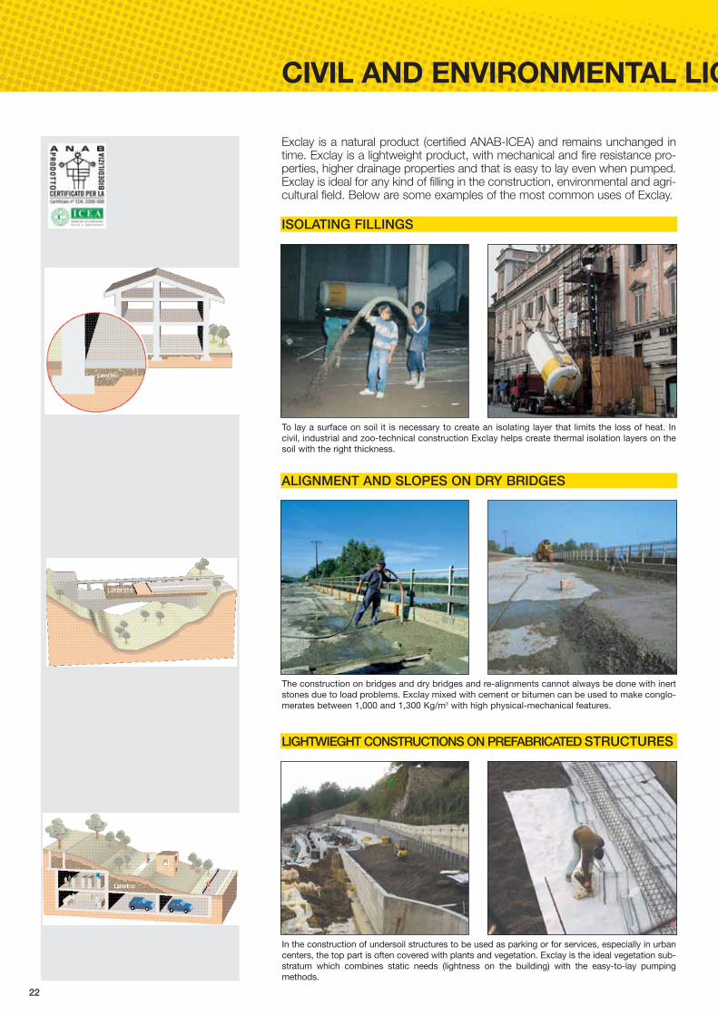
Exclay is a natural product (certified ANAB-ICEA) and remains unchanged intime. Exclay is a lightweight product, with mechanical and fire resistance pro-perties, higher drainage properties and that is easy to lay even when pumped.Exclay is ideal for any kind of filling in the construction, environmental and agri-cultural field. Below are some examples of the most common uses of Exclay.
ISOLATING FILLINGS
To lay a surface on soil it is necessary to create an isolating layer that limits the loss of heat. Incivil, industrial and zoo-technical construction Exclay helps create thermal isolation layers on thesoil with the right thickness.
ALIGNMENT AND SLOPES ON DRY BRIDGES
The construction on bridges and dry bridges and re-alignments cannot always be done with inertstones due to load problems. Exclay mixed with cement or bitumen can be used to make conglo-merates between 1,000 and 1,300 Kg/m3 with high physical-mechanical features.
LIGHTWIEGHT CONSTRUCTIONS ON PREFABRICATED STRUCTURES
In the construction of undersoil structures to be used as parking or for services, especially in urbancenters, the top part is often covered with plants and vegetation. Exclay is the ideal vegetation sub-stratum which combines static needs (lightness on the building) with the easy-to-lay pumpingmethods.
23
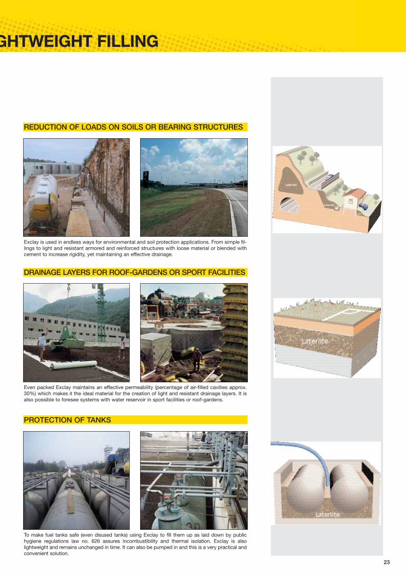
GHTWEIGHT FILLING
REDUCTION OF LOADS ON SOILS OR BEARING STRUCTURES
Exclay is used in endless ways for environmental and soil protection applications. From simple fil-lings to light and resistant armored and reinforced structures with loose material or blended withcement to increase rigidity, yet maintaining an effective drainage.
DRAINAGE LAYERS FOR ROOF-GARDENS OR SPORT FACILITIES
Even packed Exclay maintains an effective permeability (percentage of air-filled cavities approx.30%) which makes it the ideal material for the creation of light and resistant drainage layers. It isalso possible to foresee systems with water reservoir in sport facilities or roof-gardens.
PROTECTION OF TANKS
To make fuel tanks safe (even disused tanks) using Exclay to fill them up as laid down by publichygiene regulations law no. 626 assures incombustibility and thermal isolation. Exclay is alsolightweight and remains unchanged in time. It can also be pumped in and this is a very practical andconvenient solution.

24
HIGH ADHERENCE SURFACESThe adherence of a normal bituminous surface depends on the C.L.A. factor(accelerated polishing coefficient) of the used inert material. This feature doesnot always remain constant in time to the detriment of safety. Practically, afterthe superficial removal from the bitumen, the inert material becomes polishedthrough contact with the tires. After a few months of use of the road this phe-nomenon tends to reduce its adherence. 10% of weight of Exclay added to the mixture of a road surface assures theC.A.T. values (transversal friction coefficient) in time of about 60 and a reduc-tion of the braking space from 10 to 25% in relation to the speed of the vehi-cle. The company AUTOSTRADE after carrying out specific studies and controlhas been using Exclay for the past 10 years. Mixtures with Exclay can bemade both in continuous and discontinuous plants without modifying theproductive cycle. The use of low percentages in a normal mixture assureshigh adherence features with the surface.Exclay spread evenly in the mixture assures C. A. T. values higher than theminimum required and for the entire technical life of the road surface. Thelaying techniques for mixtures with Exclay are the same normally used forother mixtures. We suggest an optimal packing at a temperature between140 and 120°C.
SOUND-PROOF SURFACESExclay’s special structure reduces noise thus considerably reducing thereflection of the acoustic wave. These features combined with a well-studiedgranulation curve, confers good noise absorption values to the mixture.Acoustic controls with different control methods have been carried out in Italyand abroad. The documentation is available upon request.
ROAD SURFACESFor further information please refer to the publication “Road Surfaces” published by Laterlite
25
OTHER ROAD APPLICATIONS
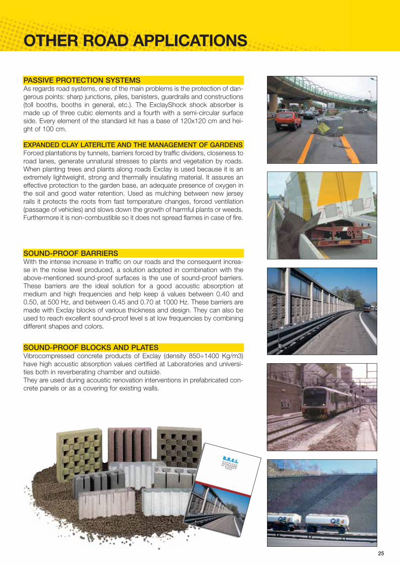
EXPANDED CLAY LATERLITE AND THE MANAGEMENT OF GARDENSForced plantations by tunnels, barriers forced by traffic dividers, closeness toroad lanes, generate unnatural stresses to plants and vegetation by roads.When planting trees and plants along roads Exclay is used because it is anextremely lightweight, strong and thermally insulating material. It assures aneffective protection to the garden base, an adequate presence of oxygen inthe soil and good water retention. Used as mulching between new jerseyrails it protects the roots from fast temperature changes, forced ventilation(passage of vehicles) and slows down the growth of harmful plants or weeds.Furthermore it is non-combustible so it does not spread flames in case of fire.
SOUND-PROOF BARRIERSWith the intense increase in traffic on our roads and the consequent increa-se in the noise level produced, a solution adopted in combination with theabove-mentioned sound-proof surfaces is the use of sound-proof barriers.These barriers are the ideal solution for a good acoustic absorption atmedium and high frequencies and help keep á values between 0.40 and0.50, at 500 Hz, and between 0.45 and 0.70 at 1000 Hz. These barriers aremade with Exclay blocks of various thickness and design. They can also beused to reach excellent sound-proof level s at low frequencies by combiningdifferent shapes and colors.
SOUND-PROOF BLOCKS AND PLATES Vibrocompressed concrete products of Exclay (density 850÷1400 Kg/m3)have high acoustic absorption values certified at Laboratories and universi-ties both in reverberating chamber and outside. They are used during acoustic renovation interventions in prefabricated con-crete panels or as a covering for existing walls.
PASSIVE PROTECTION SYSTEMSAs regards road systems, one of the main problems is the protection of dan-gerous points: sharp junctions, piles, banisters, guardrails and constructions(toll booths, booths in general, etc.). The ExclayShock shock absorber ismade up of three cubic elements and a fourth with a semi-circular surfaceside. Every element of the standard kit has a base of 120x120 cm and hei-ght of 100 cm.

26
EXPANDED CLAY LATERLITE CONCRETEFor further information please refer to the publication “Lightweight Structural Concrete” published by Laterlite
LOOSE EXPANDED CLAY LATERLITEExclay is available in the following typologies (nominal categories) beyond 0-30.
Expanded Clay Laterlite 0-2 2-3 3-8 8-20Density (UNI EN 13055-1) [Kg/m3] 700 480 380 330Crushing strength of granules (UNI EN 13055-1) [N/mm2] 4,5 2,5 1,5 0,7
LIGHT BLOCKSFor all the applications where it is necessary to stabilize Exclay with concrete (filling on slopes,tunnel blocking, filling of cavities, etc.) it is possible to create mixtures in the construction yardpumped with the “Exclay PPC” technology or pre-packaged by concrete mixing plants.
Exclay Concrete Weight Resistance [Kg/m3] [Kg/m3] [N/mm2]
Mixed Exclay 3-8 200 650 2REOEXCLAY 25 0-4 350 750 ≥ 2.5REOEXCLAY 50 0-2 400 800 ~ 5
EXCLAY STRUCTURAL AND EXCLAY TERRECOTTE Laterlite produces two other types of lightweight aggregates: “Exclay Structural” and “ExclayTerrecotte” (technical specifications in table); they are mainly used for the preparation of structuralconcrete in compliance with the regulations (Decree 09/01/96 and relating technical instructions).
EXPANDED CLAY LATERLITE CONCRETEAccording to need (supporting walls or other interventions) various mixtures can be createdsome of which are indicated in the table.
Exclay Structural 0-5 5-15 0-15Density (UNI EN 13055-1) [Kg/m3] 800 650 730Crushing strength of granules (UNI EN 13055-1) [N/mm2] 10,0 4.5 9,0
Exclay Terrecotte 0-6 6-12 0-12Density [Kg/m3] 950 800 900Crushing strength of granules (UNI EN 13055-1) [N/mm2] 12.0 7.0 7.5
STR
UC
TUR
AL
CO
NC
REI
TEN
ON
-STR
UC
TUR
AL
CO
NC
RET
E
INERT CONCRETE S.F. APPROX. AVERAGEDose in volume DENSITY RESIST.
of inert [Kg/m3] [Kg/m3] [N/mm2]
25% 75% 350sand 0-3 Exclay 3-8 (type 32.5) NO 1000 7,5
15% 35% 50% 350sand 0-3 Exclay 2-3 Exclay 3-8 (type 32.5) NO 1200 13
30% 30% 40% 3500-3 sand Exclay 0-2 Exclay 2-3 (type 42.5) SI 1400 20
20% 80% 350sand 0-3 STR 0-15 (type 42.5) SI 1600 30
40% 60% 400sand 0-3 STR 0-15 (type 42.5) SI 1800 40
30% 35% 35% 360sand 0-3 TC 0-6 TC 6-12 (type 52.5) SI 1900 50
S.F.: Super-fluidifying STR: Exclay Structural; TC: Exclay Terrecotte

27
DELIVERY MODALITIES
IN BAGS OR ALREADY PRE-MIXEDGranules sized 3-8, 8-20 (at request also 2-3) are supplied in plastic bagsof 50 l (20 bags per m3) on disposable pallets of 75 bags (3.75 m3) each.Granule sizes 2-3 and 3-8 can be supplied, at request, even dry (humi-dity level less than 1%). The Laterlite production also includes other pro-ducts (made with Exclay) already pre-mixed for different uses in the con-struction field (setting beds, structural concrete, mortar and plasters,etc.).
LOOSEAny material can be delivered with a dumper(lateral – back). For loads up to 65 m3 accor-ding to the granulations. Different granulationscan be supplied mixed with one another.
PUMPED WITH “EXCLAY PPC” TECHNOLOGYThrough “PPC” technology (Continuous Pneumatic Pumping) Exclay canbe pumped on site loose with concrete. The equipment needed is easyto transport and enables the filling of cement grout directly from the truckmixer and of Exclay directly from the truck and full trailer. The average pro-ductivity depends on the type of application and can be around 120m3/days (equal to about 2 truck and full trailer a day) with a cement doseto be established according to the use (suggested value 250 Kg per m3
Exclay).
PRE-PACKAGED BY CONCRETE MIXING PLANTSConcrete mixtures with Exclay can be packed directly in the constructionyard or at concrete mixing plants. Particularly, pumpable structural con-crete and pumpable concrete such as ReoExclay 25 and 50.
PUMPED LOOSEIt is possible to deliver loose Exclay with trucks equipped to pump thematerial in quote or in silos (up to 30 m vertical or 80-100 m horizontal).For loads up to 61 m3.

Technical assistance20149 Milano - via Correggio, 3 - ItalyTel. +39 02 48011962 - Fax +39 02 48012242www.leca.it [email protected] ©
Lat
erlit
e –
All
right
s re
serv
ed –
Par
tial r
epro
duct
ion
is p
rohi
bite
d. -
I.P.
Rev
isio
n 01
/200
6 –
Valid
from
25/
09/0
6 –
Rep
lace
s an
d ca
ncel
s al
l pre
viou
s on
es


