2.1 Project Description ............................................................................................... 12.2 Site Location and Description............................................................................... 2
4.0 RECOMMENDATIONS FOR DESIGN AND CONSTRUCTION ...................................... 44.1 Geotechnical Considerations ............................................................................... 4
4.2 Earthwork............................................................................................................. 54.2.1 Site Preparation........................................................................................ 54.2.2 Soil Stabilization ....................................................................................... 54.2.3 Material Requirements ............................................................................. 64.2.4 Compaction Requirements ....................................................................... 74.2.5 Utility Trench Backfill ................................................................................ 84.2.6 Grading and Drainage .............................................................................. 84.2.7 Earthwork Construction Considerations .................................................... 8
4.3 Foundations ......................................................................................................... 94.3.1 Shallow Foundation System ..................................................................... 9
5.0 GENERAL COMMENTS ............................................................................................... 16
APPENDIX A – FIELD EXPLORATIONExhibit A-1 Field Exploration DescriptionExhibit A-2 Site Location MapExhibit A-3 Topographic MapExhibit A-4 Site DiagramExhibit A-5 Boring Location DiagramExhibit A-6 to A-14 Boring Logs
TABLE OF CONTENTS (continued)
Responsive ■ Resourceful ■ Reliable
APPENDIX B – SUPPORTING INFORMATIONExhibit B-1 Laboratory Testing
APPENDIX C – SUPPORTING DOCUMENTSExhibit C-1 General NotesExhibit C-2 Unified Soil Classification System
Geotechnical Engineering ReportProposed Dollar General ■ Miller, MissouriDecember 8, 2014 ■ Terracon Project No. B5145058
Responsive ■ Resourceful ■ Reliable i
EXECUTIVE SUMMARYA geotechnical exploration has been performed for the proposed Dollar General Store to belocated at the southwest corner of the intersection of Highway 39 and DD in Miller, Missouri.Nine (9) borings, designated B-1 through B-9, were performed to depths of approximately 10 to20 feet below the existing ground surface. The following geotechnical considerations wereidentified:
n The fat clay (CH) soils encountered in the borings are high in plasticity and prone to volumechange with variations in moisture content. For this reason, we recommend a 24-inch thickLow Volume Change (LVC) zone be present or constructed beneath grade-supported floorslabs. The borings indicate that some of the soils in the upper 6 feet in the proposed buildingpad are high plasticity clay. If fat clay soils are observed in the near-surface building padsubgrade soils, they should be removed and replaced with LVC material.
n Some relatively high moisture content soils were encountered in the upper levels of some ofthe borings, and may be exposed in excavations and cuts. These soils may becomeunstable when disturbed. During periods of dry weather, these soils may be stable uponinitial exposure; however, these soils, if exposed, may become relatively soft and unstableunder construction traffic. We recommend that the owner budget for the possibility thatoverexcavation and/or subgrade stabilization may be required and contractors be preparedto handle potentially unstable and/or soft conditions.
n The 2009 International Building Code (IBC) seismic site classification for this site is D.
The professional opinions and recommendations presented in this report are based on evaluationof data developed by testing discrete samples obtained from widely-spaced borings. Sitesubsurface conditions have been inferred from available data, but actual subsurface conditionswill only be revealed by excavation. So that variations in subsurface conditions which may affectthe design can be addressed as they are encountered, we recommend that Terracon be retainedto observe excavation and perform tests during the site preparation, earthwork and foundationconstruction phases of the project.
This executive summary should not be separated from or used apart from this report. This reportpresents fully developed recommendations and opinions based on our understanding of theproject at the time the report was prepared. The report limitations are described in the GENERALCOMMENTS section of this report.
Responsive ■ Resourceful ■ Reliable 1
GEOTECHNICAL ENGINEERING REPORTPROPOSED DOLLAR GENERAL
MILLER, MISSOURITerracon Project No. B5145058
December 8, 2014
1.0 INTRODUCTION
A geotechnical exploration has been performed for the proposed Dollar General Store to belocated at the southwest corner of the intersection of Highway 39 and DD in Miller, Missouri.Nine (9) borings, designated B-1 through B-9, were performed to depths of approximately 10 to20 feet below the existing ground surface. Logs of the borings along with a Site Location Map,Topographic Map, Site Diagram and Boring Location Diagram are included in Appendix A of thisreport.
The purpose of these services is to provide information and geotechnical engineeringrecommendations relative to:
n subsurface soil conditions n slab design and constructionn groundwater conditions n seismic considerationsn earthwork n pavement recommendationsn foundation design and construction
2.0 PROJECT INFORMATION
2.1 Project Description
Item Description
Site layout See Appendix A, Exhibit A-5: Boring Location Diagram
Building information
The new building will be single-story, slab-on-grade structure with afootprint of approximately 9,100 sq. ft. The building will be a steel-framed structure supported on a reinforced concrete foundationsystem.
Finished floor elevation Not yet determined, assumed to be within 5 feet of existing grade.
Maximum building loads(provided)
Columns: 20 to 50 kipsWalls: 3.0 klfSlabs: less than 100 psf
Geotechnical Engineering ReportProposed Dollar General ■ Miller, MissouriDecember 8, 2014 ■ Terracon Project No. B5145058
Responsive ■ Resourceful ■ Reliable 2
Item Description
Anticipated traffic
Expected traffic loading was not provided; however, we anticipatethe new parking areas will be primarily used by personal vehicles(cars and pick-up trucks). A limited number of delivery trucks andrefuse disposal vehicles are expected in the drive lanes and loadingareas (estimated maximum of 10 trucks per week).
Site gradingA grading plan was not available at the time of this report. Weanticipate that less than 6 feet of cut and/or fill will be required toachieve finished grades.
Below-grade walls None anticipated
Retaining walls None anticipated
2.2 Site Location and Description
Item Description
Location
Southwest corner of the intersection of Highway 39 and DD inMiller, Missouri.
Existing improvementsThe site is currently vacant with a driveway along the north edge ofthe property.
Current ground cover The site is generally covered with grass and a few trees on the westend of the site.
Existing topographyA plan of the existing topography was not available. The sitegenerally slopes downward from north to south with about 8 feet ofrelief across the study area.
Geotechnical Engineering ReportProposed Dollar General ■ Miller, MissouriDecember 8, 2014 ■ Terracon Project No. B5145058
Responsive ■ Resourceful ■ Reliable 3
3.0 SUBSURFACE CONDITIONS
3.1 Typical Profile
Based on the results of the borings, subsurface conditions on the project site can begeneralized as follows:
Stratum Approximate Depth toBottom of Stratum (feet)
BoringLocations Material Description Consistency/
DensitySurface 0.25 to 0.5 All Topsoil n/a
1 5½ to 8½ All, exceptB-5 and B-6
Lean to fat clay, with varyingamounts of gravel
Variable
2 5 ½ to 10½B-2, B-3, B-4, B-5, B-7,
and B-9Clayey gravel
Mediumdense todense
3 10 to 201 All Fat clay with varying amounts ofgravel Variable
1. All borings were terminated within this stratum at their planned termination depths ranging between10 to 20 feet below grade.
Conditions encountered at each boring location are indicated on the individual boring logs.Stratification boundaries on the boring logs represent the approximate location of changes insoil types; the transition between materials may be gradual. Details for each of the borings canbe found on the boring logs in Appendix A of this report.
3.2 Groundwater
The boreholes were observed while drilling and after completion for the presence and level ofgroundwater. At the time of drilling no free water was noted within the borings. The absence ofobserved water does not mean that the boring terminated above groundwater. Due to the lowpermeability of some of the soils encountered in the borings, a relatively long period of time maybe necessary for a groundwater level to develop and stabilize in a borehole in these materials.Long-term observations in piezometers or observation wells sealed from the influence of surfacewater are often required to define groundwater levels in materials of this type.
Groundwater level fluctuations occur due to seasonal variations in the amount of rainfall, runoff,and other factors not evident at the time the borings were performed. In addition, perched watercan develop over low permeability soil strata. Therefore, groundwater levels during constructionor at other times in the life of the structures may be higher or lower than the levels indicated onthe boring logs. The possibility of groundwater level fluctuations should be considered whendeveloping the design and construction plans for the project.
Geotechnical Engineering ReportProposed Dollar General ■ Miller, MissouriDecember 8, 2014 ■ Terracon Project No. B5145058
Responsive ■ Resourceful ■ Reliable 4
4.0 RECOMMENDATIONS FOR DESIGN AND CONSTRUCTION
4.1 Geotechnical Considerations
Based on the results of the subsurface exploration, laboratory testing, and our analyses, it is ouropinion that the proposed building can be supported on shallow foundations bearing on suitablenative clay or newly placed compacted structural fill. Geotechnical considerations for thisproject include:
n Swell Potential; andn Soft subgrade potential.
4.1.1 Swell PotentialWe recommend a low volume change (LVC) zone be constructed beneath the at-grade floorslab. Using an LVC zone as recommended in this report may not eliminate all future subgradevolume change and resultant floor slab movements. However, the procedures outlined hereinshould help to reduce the potential for subgrade volume change. Existing soils can be left inplace and compacted if they are tested during construction and meet LVC materialrequirements. Details regarding this LVC zone are provided in section 4.4 Floor Slab.
4.1.2 Soft Subgrade PotentialSome relatively high moisture content soils were encountered in the upper levels of some of theborings and could be exposed in excavations and cuts. These soils may become unstablewhen disturbed. During periods of dry weather, these soils may be stable upon initial exposure;however, these soils, if exposed, could become relatively soft and unstable under constructiontraffic. Further, depending upon site conditions during construction, overexcavation orstabilization of the subgrade and/or base of overexcavations may be needed to achieve asuitable working surface. Accordingly, we recommend that the owner budget for the possibilitythat overexcavation and/or subgrade stabilization may be required and contractors be preparedto handle potentially unstable and/or soft conditions.
4.1.3 GeneralWe recommend that the exposed subgrade be thoroughly evaluated after stripping of anytopsoil and at the base of all cut areas, but prior to the start of any fill operations. Werecommend that the geotechnical engineer be retained to evaluate the bearing material for thefoundations and subgrade soils. Subsurface conditions, as identified by the field and laboratorytesting programs, have been reviewed and evaluated with respect to the proposed project plansknown to us at this time.
Geotechnical Engineering ReportProposed Dollar General ■ Miller, MissouriDecember 8, 2014 ■ Terracon Project No. B5145058
Responsive ■ Resourceful ■ Reliable 5
4.2 Earthwork
4.2.1 Site PreparationWe anticipate construction will be initiated by the removal of pavements and landscaping,topsoil, or vegetation that may be present. All existing utilities should also be properlyabandoned or relocated. This should include removal of all poorly compacted trench backfillextending into the proposed building area.
Fat clay soils should not be placed or remain present in the upper 2 feet below the plannedbottom of floor slabs and other flatwork abutting the structure. Suitable materials in this 2-foot-thick zone should meet the LVC requirements defined in section 4.2.3 Material Requirementsof this report.
We recommend that the exposed subgrade be thoroughly evaluated by a geotechnical engineerprior to placement of new fill. The soils on the site are sensitive to disturbance fromconstruction equipment traffic, particularly during wet periods. Excessively wet or dry materialshould either be removed or moisture conditioned and recompacted. The exposed subgrade,including areas of existing undocumented fill, should be proofrolled where possible to aid inlocating loose or soft areas. Proofrolling can be performed with a loaded, tandem-axle dumptruck. If unsuitable areas are observed during construction, subgrade improvement will then benecessary to establish a suitable subgrade support condition. Subgrade stabilization isdiscussed in section 4.2.2 Soil Stabilization.
4.2.2 Soil StabilizationMethods of subgrade improvement, as described below, could include scarification, moistureconditioning and recompaction, removal of unstable materials and replacement with granular fill(with or without geosynthetics) and chemical stabilization. The appropriate method ofimprovement, if required, would be dependent on factors such as schedule, weather, the size ofthe area to be stabilized, and the nature of the instability. More detailed recommendations canbe provided during construction as the need for subgrade stabilization occurs. Performing sitegrading operations during warm seasons and dry periods would help to reduce the amount ofsubgrade stabilization required.
If the exposed subgrade is unstable during proofrolling operations, it could be stabilized usingone of the methods outlined below.
n Scarification and Compaction – It may be feasible to scarify, dry, and compact theexposed soils. The success of this procedure would depend primarily upon favorableweather and sufficient time to dry the soils. Stable subgrades likely would not be achievableif the thickness of the unstable soil is greater than about 1 foot, if the unstable soil is at ornear groundwater levels, or if construction is performed during a period of wet or coolweather when drying is difficult.
Geotechnical Engineering ReportProposed Dollar General ■ Miller, MissouriDecember 8, 2014 ■ Terracon Project No. B5145058
Responsive ■ Resourceful ■ Reliable 6
n Crushed Stone – The use of crushed stone or gravel is the most common procedure toimprove subgrade stability. Typical undercut depths would be expected to range from about6 to 30 inches below finished subgrade elevation with this procedure. The use of highmodulus geotextiles (i.e., engineering fabric or geogrid) could also be considered afterunderground work such as utility construction is completed. Prior to placing the fabric orgeogrid, we recommend that all below-grade construction, such as utility line installation, becompleted to avoid damaging the fabric or geogrid. Equipment should not be operatedabove the fabric or geogrid until one full lift of crushed stone fill is placed above it. Themaximum particle size of granular material placed over geotextile fabric or geogrid shouldmeet the manufacturer’s specifications, and generally should not exceed 1½ inches.
n Chemical Stabilization – Improvement of subgrades with Portland cement, lime kiln dust,Code L, or class C fly ash could be considered for improving unstable soils. Chemicalmodification should be performed by a prequalified contractor having experience withsuccessfully stabilizing subgrades in the project area on similar sized projects with similarsoil conditions. Results of chemical analysis of the additive materials should be provided tothe geotechnical engineer prior to use. The hazards of chemicals blowing across the site oronto adjacent property should also be considered. Additional testing would be needed todevelop specific recommendations to improve subgrade stability by blending chemicals withthe site soils. Additional testing could include, but not be limited to, evaluating variousadmixtures, the optimum amounts required, the presence of sulfates in the soil, and freeze-thaw durability of the subgrade.
Further evaluation of the need and recommendations for subgrade stabilization can be providedduring construction as the geotechnical conditions are exposed.
4.2.3 Material RequirementsMaterials that will be used as fill should be free of organic matter and debris. Frozen materialsshould not be used, and fill should not be placed on a frozen subgrade. A sample of eachmaterial type should be submitted to Terracon for evaluation.
Fill Type1 USCSClassification Acceptable Location for Placement
Lean Clay CL (LL<50)All locations and elevations, except asLVC material unless material explicitly
meets LVC requirements.Moderate to High
Plasticity Material2CH or CL (LL≥45 or
PI≥25) > 24 inches below building finished grade3
Geotechnical Engineering ReportProposed Dollar General ■ Miller, MissouriDecember 8, 2014 ■ Terracon Project No. B5145058
Responsive ■ Resourceful ■ Reliable 7
Well-gradedGranular3 GM, GC, SM, or SC All locations and elevations
Low Volume Change(LVC) Material 4
CL (LL<45 &PI<25) or granular
Material 3All locations and elevations
1. Compacted structural fill should consist of approved materials that are free of organicmatter and debris. Frozen material should not be used, and fill should not be placed on afrozen subgrade. A sample of each material type should be submitted to Terracon forevaluation.
2. Delineation of moderate to highly plastic clays should be performed in the field by aqualified geotechnical engineer or their representative, and could require additionallaboratory testing. If fat clay fill material contains greater than 35% granular materialretained on a ¾-inch sieve, it may be used in the 24-inch thick low volume change zone.
3. Similar to crushed limestone aggregate or crushed stone containing at least 15% lowplasticity fines may also be used. Material should be approved by the geotechnicalengineer.
4. Low plasticity cohesive soil or granular soil having low plasticity fines. Material should beapproved by the geotechnical engineer.
4.2.4 Compaction RequirementsItem Description
Fill Lift Thickness 1 9 inches or less in loose thickness
Compaction Requirements 2 At least 95% of the material’s maximum standardProctor dry density 3
Moisture Content ClaySoil
LL<40 -2% to +2% of optimum moisture content value 3
LL>40 0 to 4% above the optimum moisture content value 3
Moisture Content Granular Material Workable moisture levels 4
1. Reduced lift thicknesses are recommended in confined areas (e.g., utility trenches,foundation excavations, and foundation backfill) and when hand-operated compactionequipment is used.
2. We recommend that engineered fill be tested for moisture content and compaction duringplacement. Should the results of the in-place density tests indicate the specified moistureor compaction limits have not been met, the area represented by the test should bereworked and retested as required until the specified moisture and compactionrequirements are achieved.
3. As determined by the standard Proctor test (ASTM D 698).4. Specifically, moisture levels should be maintained low enough to allow for satisfactory
compaction to be achieved without the cohesionless fill material pumping when
Geotechnical Engineering ReportProposed Dollar General ■ Miller, MissouriDecember 8, 2014 ■ Terracon Project No. B5145058
Responsive ■ Resourceful ■ Reliable 8
proofrolled.
4.2.5 Utility Trench BackfillAll trench excavations should be made with sufficient working space to permit constructionincluding backfill placement and compaction. If utility trenches are backfilled with relativelyclean granular material, attempts should be made to limit the amount of fine migration into theclean stone. Fine migration into clean granular fill may result in unanticipated localizedsettlements over a period of time. To help limit the amount of fine migration, Terraconrecommends the use of a geotextile fabric that is designed to prevent fine migration in areas ofcontact between clean stone and fine-grained soils. Terracon also recommends that cleanstone be tracked or tamped in place where possible in order to limit the amount of futuredensification which may cause localized settlements over time.
Utility trenches are common sources of water infiltration and migration. All utility trenches thatpenetrate beneath the building should be effectively sealed to restrict water intrusion and flowthrough the trenches that could migrate below the building. We recommend constructing aneffective “trench plug” that extends at least 5 feet out from the face of the building exterior. Theplug material should consist of lean clay compacted at a water contact at or above the soil’soptimum water content. The lean clay fill should be placed to completely surround the utility lineand be compacted in accordance with the recommendations in this report.
4.2.6 Grading and DrainageFinal grades should slope away from the structure on all sides to prevent ponding of water.Gutters and downspouts should drain water a minimum of 10 feet beyond the footprint of theproposed structure. This can be accomplished through the use of splash-blocks, downspoutextensions, and flexible pipes that are designed to attach to the end of the downspout. Flexiblepipe should only be used if it is daylighted in such a manner that it gravity-drains collectedwater. Splash-blocks should also be considered below hose bibs and water spigots.
4.2.7 Earthwork Construction ConsiderationsIn periods of dry weather, the surficial soils may be of sufficient strength to allow fill constructionon the stripped and grubbed ground surface. However, unstable subgrade conditions coulddevelop during general construction operations, particularly if the soils are wet or subjected torepetitive construction traffic. The use of low ground pressure construction equipment would aidin reducing subgrade disturbance. The use of remotely operated equipment, such as abackhoe, would be beneficial to perform cuts and reduce subgrade disturbance. If unstablesubgrade conditions are encountered, stabilization measures, as described in section 4.2.2 SoilStabilization will need to be employed.
Temporary excavations will be required during construction. The contractor is usuallyresponsible for designing and constructing stable, temporary excavations and should shore,slope or bench the sides of the excavations as required, to maintain stability of both the
Geotechnical Engineering ReportProposed Dollar General ■ Miller, MissouriDecember 8, 2014 ■ Terracon Project No. B5145058
Responsive ■ Resourceful ■ Reliable 9
excavation sides and bottom. All excavations should comply with applicable local, state andfederal safety regulations, including the current OSHA Excavation and Trench SafetyStandards.
The contractor is responsible for selecting and implementing the appropriate dewateringprocedures, if required during construction. Although groundwater was not encountered in theborings at depths expected to affect foundation excavations, it may be encountered duringfoundation excavation or in other excavation activities. In addition, some surface and/or perchedgroundwater may enter foundation excavations during construction. The volume of waterseepage into shallow isolated excavations may be controllable with an appropriate number ofsump pits and pumps; however, more extensive dewatering and/or subgrade stabilization maybe required to facilitate construction if larger and/or deeper areas of cut are performed duringearthwork operations.
Upon completion of filling and grading, care should be taken to maintain the subgrade moisturecontent prior to construction of floor slabs and pavements. Construction traffic over thecompleted subgrade should be avoided to the extent practical. The site should also be gradedto prevent ponding of surface water on the prepared subgrades or in excavations. If thesubgrade should become frozen, desiccated, saturated, or disturbed, the affected materialshould be removed or these materials should be scarified, moisture conditioned, andrecompacted prior to foundation construction.
Trees or other vegetation whose root systems have the ability to remove excessive moisturefrom the subgrade and foundation soils should not be planted next to the structure. Trees andshrubbery should be kept away from the exterior of the structure a distance at least equal totheir expected mature height.
The geotechnical engineer should be retained during the construction phase of the project toobserve earthwork and to perform necessary tests and observations during subgradepreparation; proofrolling; placement and compaction of controlled compacted fills; backfilling ofexcavations into the completed subgrade, and just prior to construction of slabs.
4.3 Foundations
The proposed building can be supported using a shallow foundation system bearing on suitablenative soils, or newly placed engineered fill above suitable native soils. Shallow foundationsystem design recommendations for the proposed structure are presented in the followingsections.
4.3.1 Shallow Foundation System
Geotechnical Engineering ReportProposed Dollar General ■ Miller, MissouriDecember 8, 2014 ■ Terracon Project No. B5145058
Responsive ■ Resourceful ■ Reliable 10
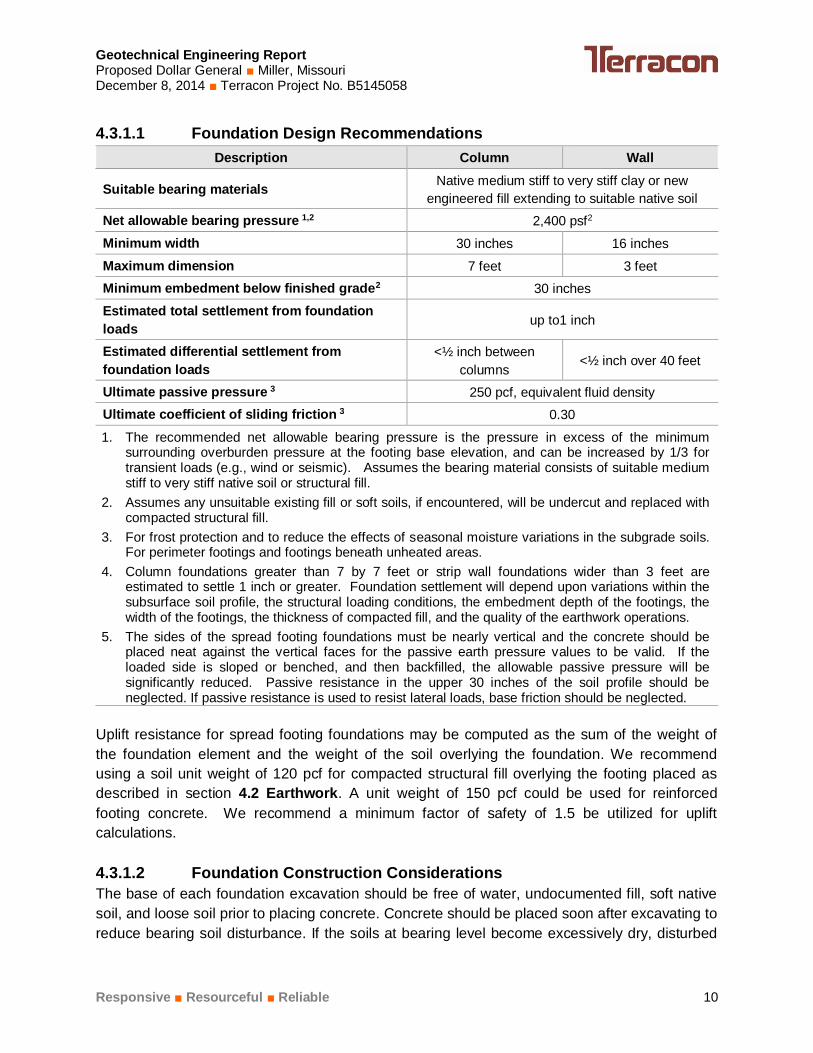
4.3.1.1 Foundation Design RecommendationsDescription Column Wall
Suitable bearing materials Native medium stiff to very stiff clay or newengineered fill extending to suitable native soil
Net allowable bearing pressure 1,2 2,400 psf2
Minimum width 30 inches 16 inchesMaximum dimension 7 feet 3 feetMinimum embedment below finished grade2 30 inchesEstimated total settlement from foundationloads up to1 inch
Ultimate passive pressure 3 250 pcf, equivalent fluid densityUltimate coefficient of sliding friction 3 0.301. The recommended net allowable bearing pressure is the pressure in excess of the minimum
surrounding overburden pressure at the footing base elevation, and can be increased by 1/3 fortransient loads (e.g., wind or seismic). Assumes the bearing material consists of suitable mediumstiff to very stiff native soil or structural fill.
2. Assumes any unsuitable existing fill or soft soils, if encountered, will be undercut and replaced withcompacted structural fill.
3. For frost protection and to reduce the effects of seasonal moisture variations in the subgrade soils.For perimeter footings and footings beneath unheated areas.
4. Column foundations greater than 7 by 7 feet or strip wall foundations wider than 3 feet areestimated to settle 1 inch or greater. Foundation settlement will depend upon variations within thesubsurface soil profile, the structural loading conditions, the embedment depth of the footings, thewidth of the footings, the thickness of compacted fill, and the quality of the earthwork operations.
5. The sides of the spread footing foundations must be nearly vertical and the concrete should beplaced neat against the vertical faces for the passive earth pressure values to be valid. If theloaded side is sloped or benched, and then backfilled, the allowable passive pressure will besignificantly reduced. Passive resistance in the upper 30 inches of the soil profile should beneglected. If passive resistance is used to resist lateral loads, base friction should be neglected.
Uplift resistance for spread footing foundations may be computed as the sum of the weight ofthe foundation element and the weight of the soil overlying the foundation. We recommendusing a soil unit weight of 120 pcf for compacted structural fill overlying the footing placed asdescribed in section 4.2 Earthwork. A unit weight of 150 pcf could be used for reinforcedfooting concrete. We recommend a minimum factor of safety of 1.5 be utilized for upliftcalculations.
4.3.1.2 Foundation Construction ConsiderationsThe base of each foundation excavation should be free of water, undocumented fill, soft nativesoil, and loose soil prior to placing concrete. Concrete should be placed soon after excavating toreduce bearing soil disturbance. If the soils at bearing level become excessively dry, disturbed
Geotechnical Engineering ReportProposed Dollar General ■ Miller, MissouriDecember 8, 2014 ■ Terracon Project No. B5145058
Responsive ■ Resourceful ■ Reliable 11
or saturated, or frozen, the affected soil should be removed prior to placing concrete. A leanconcrete mudmat should be placed over the bearing soils if the excavations must remain openfor an extended period of time. It is recommended that the geotechnical engineer be retained toobserve and test the soil foundation bearing materials.
Although groundwater was not encountered in the borings at depths expected to affectfoundation excavations, it may be encountered during foundation excavation or in otherexcavation activities. In addition, some surface and/or perched groundwater may enterfoundation excavations during construction. It is anticipated that any water entering foundationexcavations from these sources can be removed using sump pumps or gravity drainage.
If unsuitable bearing soils (e.g., undocumented fill or soft native soils) are encountered in footingexcavations, the excavation should be extended deeper to suitable soils. The footing could thenbear directly on these soils at the lower level or on lean concrete backfill placed in theexcavations. As an alternative, the footings could also bear on properly compacted structuralbackfill extending down to the suitable soils. Overexcavation for compacted structural fillplacement below footings should extend laterally beyond all edges of the footings at least 8inches per foot of overexcavation depth below footing base elevation. The overexcavationshould then be backfilled per recommendations provided in section 4.2 Earthwork up to thefooting base elevation. The overexcavation and backfill procedure is illustrated in the followingfigure..
4.4 Floor Slabs
Grade-supported floor slabs should be supported on a minimum of 24 inches of LVC material.LVC fill should be placed and compacted as recommended in section 4.2 Earthwork.
Geotechnical Engineering ReportProposed Dollar General ■ Miller, MissouriDecember 8, 2014 ■ Terracon Project No. B5145058
Floor slab support 1, 2 A minimum 24-inch thick low volume change (LVC)layer over suitable native clay or engineered fill
Modulus of subgrade reaction 100 pounds per square inch per inch (psi/in) for pointloading conditions
Granular course beneath slab 3, 4, 5 Minimum 4 inchesCapillary break layer thickness 4, 5 Minimum 6 inches1. We recommend an LVC layer be present below the floor slab. This layer should be at
least 24 inches thick and should meet the LVC material criteria outlined in this report insection 4.2 Earthwork. Where existing soils meet the LVC criteria, they should bemoisture conditioned and recompacted as recommended in this report.
2. We recommend subgrades be maintained in a relatively moist condition until the floor slabis constructed. If the subgrade should become excessively wet or dry prior to constructionof floor slabs, the affected material should be removed or the materials scarified, moistureconditioned, and recompacted. Upon completion of grading operations in the buildingarea, care should be taken to maintain the recommended subgrade moisture content anddensity prior to construction of the building floor slab.
3. If the purpose of this layer is solely to create a level base for concrete placement tomaintain a more uniform slab thickness, well-graded sand, gravel or crushed stone can beused.
4. If penetration of moisture vapor through the slab is a concern, in our opinion the floor slabdesign should include a capillary break layer in addition to a vapor retarder (refer to ACI302 and/or ACI 360 for procedures and cautions regarding the use and placement ofvapor retarders). In our opinion, capillary break layers should be comprised of granularmaterials that have less than 5 percent fines (material passing the #200 sieve). Otherdesign considerations such as cold temperatures and condensation development couldwarrant addition design considerations.
5. These granular materials may be considered part of the LVC zone.
Where appropriate, saw-cut control joints should be placed in the slab to help control thelocation and extent of cracking. For additional recommendations refer to the ACI DesignManual. Joints or cracks in floor slabs that develop should be sealed with a waterproof, non-extruding compressible compound specifically recommended for concrete and wetenvironments.
The use of a vapor retarder should be considered beneath concrete slabs-on-grade that will becovered with wood, tile, carpet or other moisture sensitive or impervious coverings, or when theslab will support equipment sensitive to moisture. When conditions warrant the use of a vapor
Geotechnical Engineering ReportProposed Dollar General ■ Miller, MissouriDecember 8, 2014 ■ Terracon Project No. B5145058
Responsive ■ Resourceful ■ Reliable 13
retarder, the slab designer should refer to ACI 302 and/or ACI 360 for procedures and cautionsregarding the use and placement of a vapor retarder.
4.4.2 Floor Slab Construction ConsiderationsOn most project sites, the grading is generally accomplished early in the construction phase.However as construction proceeds, the subgrade may be disturbed due to utility excavations,construction traffic, desiccation, rainfall, etc. As a result, the floor slab subgrade may not besuitable for placement of base rock and concrete and corrective action may be required.
Prior to placement of the base aggregate, we recommend that the floor slab subgrade be roughgraded and then thoroughly evaluated for stability, uniformity and moisture. If there is noconflict with installed utilities, we recommend the subgrade be proofrolled with a loaded,tandem-axle dump truck. During the evaluations, particular attention should be paid to hightraffic areas that were rutted and disturbed earlier and to areas where backfilled trenches arelocated. Areas where unsuitable conditions are located should be repaired by removing andreplacing the affected material with properly compacted fill. All floor slab subgrade areas shouldbe moisture conditioned and properly compacted to the recommendations in this reportimmediately prior to placement of the aggregate base and concrete.
4.5 Seismic Considerations
Code Used Site Classification
2009 International Building Code (IBC) 1 D 2
1. In general accordance with the 2009 International Building Code, Table 1613.5.2.2. The 2009 International Building Code requires a site soil profile determination extending to a depth
of 100 feet for seismic site classification. The current scope requested does not include therequired 100-foot soil profile determination. Borings for this report extended to a maximum depthof approximately 20 feet and the site classification assumes that similar or stiffer soils extend to atleast 100 feet. Additional exploration to deeper depths or a geophysical exploration could beconsidered to further evaluate the seismic site class.
4.6 Retaining Walls
It is Terracon’s understanding that retaining walls will not be utilized at the subject site for thesupport of buildings or pavement areas. If retaining walls are planned or needed to support thebuilding or parking areas, Terracon should be contacted before the construction of the retainingwall to provide additional recommendations concerning the retaining wall construction andlocation of the retaining wall. The improper use and construction of retaining walls may lead tofoundation failure, floor slab failure, and overall site instability. Non-reinforced block retainingwalls of any height should not be placed within the influence area of the building foundations.
Geotechnical Engineering ReportProposed Dollar General ■ Miller, MissouriDecember 8, 2014 ■ Terracon Project No. B5145058
Responsive ■ Resourceful ■ Reliable 14
4.7 Pavements
4.7.1 Pavement Subgrade PreparationOn most project sites, the grading is accomplished relatively early in the construction phase.Fills are placed and compacted in a uniform manner. However, as construction proceeds,excavations are made into these areas, rainfall and surface water saturates some areas, heavytraffic from concrete trucks and other delivery vehicles disturbs the subgrade and many surfaceirregularities are filled in with loose soils to improve stability temporarily. As a result, thepavement subgrades, initially prepared early in the project, should be carefully evaluated as thetime for pavement construction approaches.
We recommend the moisture content and density of the upper 9 inches of the subgrade beevaluated and the pavement subgrades be proofrolled within two days prior to commencementof actual paving operations. Areas not in compliance with the required ranges of moisture ordensity should be moisture conditioned and recompacted. Particular attention should be paid tohigh traffic areas that were rutted and disturbed earlier and to areas where backfilled trenchesare located. Areas where unsuitable conditions are located should be repaired by removing andreplacing the material with compacted structural fill.
After proofrolling and repairing deep subgrade deficiencies, the entire subgrade should bescarified and developed as recommended in section 4.2 Earthwork to provide a more uniformsubgrade for pavement construction. Areas that appear desiccated (dry) following site strippingmay require further undercutting and moisture conditioning. If a significant precipitation eventoccurs after the evaluation or if the surface becomes disturbed, the subgrade should bereviewed by qualified personnel immediately prior to paving. The subgrade should be in itsfinished form at the time of the final review.
4.7.2 Pavement Design ConsiderationsTraffic loading was not provided; however, we anticipate the new parking areas will be primarilyused by personal vehicles (cars and pick-up trucks). A limited number of delivery trucks andrefuse disposal vehicles are expected in the drive lanes and loading areas (estimated maximumof 10 trucks per week).
Pavement design methods are intended to provide structural sections with adequate thicknessover a particular subgrade such that wheel loads are reduced to a level the subgrade cansupport. Pavement performance is affected by its surroundings. In addition to providingpreventive maintenance, the civil engineer should consider the following recommendations inthe design and layout of pavements:
n Final grade adjacent to parking lots and drives should slope down from pavement edges ata minimum 2 percent;
Geotechnical Engineering ReportProposed Dollar General ■ Miller, MissouriDecember 8, 2014 ■ Terracon Project No. B5145058
Responsive ■ Resourceful ■ Reliable 15
n The subgrade and the pavement surface should have a minimum 2 percent slope topromote proper surface drainage;
n Drainage should be provided for the pavement base course;n Joint sealant should be installed and cracks sealed immediately;n All landscaped areas in, or adjacent to pavements should be sealed to reduce moisture
migration to subgrade soils;n Compacted, low permeability backfill should be placed against the exterior side of curbs and
gutters; and,n To reduce the likelihood of water seeping beneath curbs into the pavement base course;
curb, gutter and/or sidewalks should bear directly on clay subgrade soils rather than onunbound granular base course materials.
4.7.3 Estimates of Minimum Pavement ThicknessAsphaltic concrete pavements can be used for pavements such as drive lanes and parkingareas. We recommend portland cement concrete (PCC) pavements for entrance aprons, trashcontainer pads, loading docks, drive-through lanes, and in any other areas subjected to heavywheel loads and/or channelized or turning traffic.
Recommended thicknesses for medium and light-duty areas are provided in the table below.
Pavement Section Thickness (inches)
Traffic Area AlternativeAsphalt Concrete Portland
CementConcrete 1
AggregateBase
Course 2
TotalThicknessSurface
CourseBase
Course
Light Duty(car parking)
PCC -- -- 5.0 4.0 9
ACC 3.0 -- -- 8.0 11
Medium Duty(drives and loading
areas)
PCC -- -- 6.0 4.0 10
ACC 2.0 3.0 -- 8.0 13
Trash ContainerPad 3 PCC -- -- 7.0 4.0 11
1. 4,000 psi at 28 days, 4-inch maximum slump and 5 to 7 percent air entrained. PCC pavements arerecommended for trash container pads and in any other areas subjected to heavy wheel loadsand/or turning traffic.
2. Crushed stone (MoDOT Type 5 aggregate)3. The trash container pad should be large enough to support the container and the tipping axle of the
collection truck.
Although not required for structural support, a minimum 4- inch-thick aggregate base courselayer is recommended for the PCC pavements to help reduce the potential for slab curl,shrinkage cracking, and subgrade “pumping” through joints. Proper joint spacing will also be
Geotechnical Engineering ReportProposed Dollar General ■ Miller, MissouriDecember 8, 2014 ■ Terracon Project No. B5145058
Responsive ■ Resourceful ■ Reliable 16
required for PCC pavements to resist excessive slab curling and shrinkage cracking. All jointsshould be sealed to restrict entry of foreign material and dowelled where necessary for loadtransfer.
4.7.4 Pavement DrainagePavements should be sloped to provide rapid drainage of surface water. Water allowed to pondon or adjacent to the pavements could saturate the subgrade and contribute to prematurepavement deterioration. In addition, the pavement subgrades should be graded to providepositive drainage within the granular base section. We recommend the subgrades beneath thepavement sections be graded to slope toward the storm water catch basins. A drainagecollection and removal system (e.g., finger drains) should be used to allow water in the granularbase to enter the storm sewers, or otherwise be removed from the granular base.
4.7.5 Pavement MaintenanceThe pavement sections provided in this report represent minimum recommended thicknessesand, as such, periodic maintenance should be anticipated. Therefore preventive maintenanceshould be planned and provided for through an on-going pavement management program.Maintenance activities are intended to slow the rate of pavement deterioration, and to preservethe pavement investment. Maintenance consists of both localized maintenance (e.g., crack andjoint sealing and patching) and global maintenance (e.g., surface sealing). Preventivemaintenance is usually the first priority when implementing a pavement maintenance program.Additional engineering observation is recommended to determine the type and extent of a costeffective program. Even with periodic maintenance, some movements and related crackingmay still occur and repairs may be required.
5.0 GENERAL COMMENTS
Terracon should be retained to review the final design plans and specifications so commentscan be made regarding interpretation and implementation of our geotechnical recommendationsin the design and specifications. Terracon should also be retained to provide observation andtesting services during grading, excavation, foundation construction and other earth-relatedconstruction phases of the project.
The analysis and recommendations presented in this report are based upon the data obtainedfrom the borings performed at the indicated locations and from other information discussed inthis report. This report does not reflect variations that may occur between borings, across thesite, or due to the modifying effects of construction or weather. The nature and extent of suchvariations may not become evident until during or after construction. If variations appear, weshould be immediately notified so that further evaluation and supplemental recommendationscan be provided.
Geotechnical Engineering ReportProposed Dollar General ■ Miller, MissouriDecember 8, 2014 ■ Terracon Project No. B5145058
Responsive ■ Resourceful ■ Reliable 17
The scope of services for this project does not include either specifically or by implication anyenvironmental or biological (e.g., mold, fungi, bacteria) assessment of the site or identification orprevention of pollutants, hazardous materials or conditions. If the owner is concerned about thepotential for such contamination or pollution, other studies should be undertaken.
This report has been prepared for the exclusive use of our client for specific application to theproject discussed and has been prepared in accordance with generally accepted geotechnicalengineering practices. No warranties, either express or implied, are intended or made. Sitesafety, excavation support, and dewatering requirements are the responsibility of others. In theevent that changes in the nature, design, or location of the project as outlined in this report areplanned, the conclusions and recommendations contained in this report shall not be consideredvalid unless Terracon reviews the changes and either verifies or modifies the conclusions of thisreport in writing.
APPENDIX AFIELD EXPLORATION
Geotechnical Engineering ReportProposed Dollar General ■ Miller, MissouriDecember 8, 2014 ■ Terracon Project No. B5145058
Responsive ■ Resourceful ■ Reliable Exhibit A-1
Field Exploration DescriptionThe boring locations were laid out in the field using a scaled site plan provided by the client andreferencing available site features. Angles were estimated. The ground surface elevations atthe boring locations were obtained using an engineer’s level and survey rod and were roundedto the nearest ½-foot. The elevations are referenced to the top of the manhole west of HighwayDD on the property, which was assigned an elevation of 100.0 feet. The locations andelevations of the borings should be considered accurate only to the degree implied by themeans and methods used to define them.
The borings were drilled with an ATV-mounted, rotary drill rig using continuous-flight, hollow-stem augers to advance the boreholes through soils. Samples of the soils encountered in theborings were obtained using the split-barrel sampling procedures.
In the split-barrel sampling procedure, the number of blows required to advance a standard 2-inch O.D. split-barrel sampler the last 12 inches of the typical total 18-inch penetration by meansof a 140-pound hammer with a free fall of 30 inches, is the standard penetration resistancevalue (SPT N-value). This value is used to estimate the in-situ relative density of cohesionlesssoils and the consistency of cohesive soils.
A CME automatic SPT hammer was used to advance the split-barrel sampler in the boringsperformed on this site. A significantly greater efficiency is achieved with the automatic hammercompared to the conventional safety hammer operated with a cathead and rope. This higherefficiency has an appreciable effect on the SPT N-value. The effect of this efficiency has beenconsidered in the interpretation and analysis of the subsurface information for this report.
The samples were tagged for identification, sealed to reduce moisture loss, and taken to ourlaboratory for further observation, testing, and classification. Information provided on the boringlogs attached to this report includes soil descriptions, consistency evaluations, boring depths,sampling intervals, and groundwater conditions. The borings were backfilled with auger cuttingsprior to the drill crew leaving the site.
A field log of each boring was prepared by the drill crew. These logs included visualclassifications of the materials encountered during drilling as well as the driller’s interpretation ofthe subsurface conditions between samples. Final boring logs included with this reportrepresent the engineer's interpretation of the field logs and include modifications based onlaboratory observation and tests of the samples.
SITE LOCATION MAP
A-2
Exhibit
Project Site
4765 W. Junction St. Springfield, MO 65802
P [417] 764 5100 F [417] 864 0871
B5145058
12/4/14
RTH
CJW
TGA
TGA
GRAPHIC
Project Manager:
Drawn by:
Checked by:
Approved by:
Project No.
Scale:
File Name:
Date:B5145058_DIAG
PROPOSED DOLLAR GENERAL STORESWC OF HWY 39 and DD
MILLER, MISSOURI
TOPOGRAPHIC MAP
A-3
Exhibit
Project Site
Mo
Mo
Mo
B5145058
12/4/14
RTH
CJW
TGA
TGA
GRAPHIC
Project Manager:
Drawn by:
Checked by:
Approved by:
Project No.
Scale:
File Name:
Date:B5145058_DIAG
4765 W. Junction St. Springfield, MO 65802
P [417] 764 5100 F [417] 864 0871
PROPOSED DOLLAR GENERAL STORESWC OF HWY 39 and DD
MILLER, MISSOURI
SITE DIAGRAM
A-4B5145058
12/4/14
RTH
CJW
TGA
TGA
N/A
Project Manager:
Drawn by:
Checked by:
Approved by:
Project No.
Scale:
File Name:
Date:
Exhibit
B5145058_DIAG
1. BASE DRAWING PROVIDED BY OTHERS2. DIAGRAM IS FOR GENERAL LOCATION ONLY,AND IS NOT INTENDED FOR CONSTRUCTIONPURPOSES
NOTES
PROPOSED DOLLAR GENERAL STORESWC OF HWY 39 and DD
MILLER, MISSOURI4765 W. Junction St. Springfield, MO 65802
P [417] 764 5100 F [417] 864 0871
BORING LOCATION DIAGRAM
A-5B5145058
12/4/14
RTH
CJW
TGA
TGA
N/A
Project Manager:
Drawn by:
Checked by:
Approved by:
Project No.
Scale:
File Name:
Date:
Exhibit
B5145058_DIAG
1. BASE DRAWING PROVIDED BY OTHERS2. DIAGRAM IS FOR GENERAL LOCATION ONLY,AND IS NOT INTENDED FOR CONSTRUCTIONPURPOSES
See Exhibit A1 for description of field procedures
See Appendix B for description of laboratoryprocedures and additional data (if any).
See Appendix C for explanation of symbols andabbreviations.Elevations were measured in the field using anengineer's level and grade rod.
PROJECT: Dollar General Store - Miller, MO
FIE
LD T
ES
TR
ES
ULT
S
SA
MP
LEN
UM
BE
R
LAB
OR
AT
OR
YT
OR
VA
NE
/HP
(ps
f)
WA
TE
RC
ON
TE
NT
(%
)
DR
Y U
NIT
WE
IGH
T (
pcf)
ATTERBERGLIMITS
LL-PL-PI Approximate Surface Elev: 98.0 (Ft.) +/-
ELEVATION (Ft.)
SA
MP
LE T
YP
E
WA
TE
R L
EV
EL
OB
SE
RV
AT
ION
S
DE
PT
H (
Ft.)
5
10R
EC
OV
ER
Y (
In.)
Groundwater not encountered
WATER LEVEL OBSERVATIONS
APPENDIX BSUPPORTING INFORMATION
Geotechnical Engineering ReportProposed Dollar General ■ Miller, MissouriDecember 8, 2014 ■ Terracon Project No. B5145058
Responsive ■ Resourceful ■ Reliable Exhibit B-1
Laboratory TestingSoil samples were tested in the laboratory to measure their natural water content (ASTMD4959). A hand penetrometer was used to estimate the unconfined compressive strength ofsome cohesive samples. The hand penetrometer has been correlated with unconfinedcompression tests and provides a better estimate of soil consistency than visual examinationalone. Atterberg limits tests (ASTM D4318) were performed on selected samples. The testresults are provided on the boring logs included in Appendix A.
As part of the testing program, samples were examined in our laboratory and classified inaccordance with the General Notes and the Unified Soil Classification System (USCS) based onthe material's texture and plasticity (ASTM D2487 and ASTM D2488). The USCS group symbolis shown on the boring logs, and a brief description of the USCS is included with this report inAppendix C.
Procedural standards noted above are for reference to methodology in general. In some cases,variations to methods are applied as a result of local practice or professional judgment.
APPENDIX CSUPPORTING DOCUMENTS
Exhibit C-2
UNIFIED SOIL CLASSIFICATION SYSTEM
Criteria for Assigning Group Symbols and Group Names Using Laboratory Tests A Soil Classification
Group Symbol
Group Name B
Coarse Grained Soils: More than 50% retained on No. 200 sieve
Gravels: More than 50% of coarse fraction retained on No. 4 sieve
Clean Gravels: Less than 5% fines C
Cu 4 and 1 Cc 3 E GW Well-graded gravel F
Cu 4 and/or 1 Cc 3 E GP Poorly graded gravel F
Gravels with Fines: More than 12% fines C
Fines classify as ML or MH GM Silty gravel F,G,H
Fines classify as CL or CH GC Clayey gravel F,G,H
Sands: 50% or more of coarse fraction passes No. 4 sieve
Clean Sands: Less than 5% fines D
Cu 6 and 1 Cc 3 E SW Well-graded sand I
Cu 6 and/or 1 Cc 3 E SP Poorly graded sand I
Sands with Fines: More than 12% fines D
Fines classify as ML or MH SM Silty sand G,H,I
Fines classify as CL or CH SC Clayey sand G,H,I
Fine-Grained Soils: 50% or more passes the No. 200 sieve
Silts and Clays: Liquid limit less than 50
Inorganic: PI 7 and plots on or above “A” line J CL Lean clay K,L,M
PI 4 or plots below “A” line J ML Silt K,L,M
Organic: Liquid limit - oven dried
0.75 OL Organic clay K,L,M,N
Liquid limit - not dried Organic silt K,L,M,O
Silts and Clays: Liquid limit 50 or more
Inorganic: PI plots on or above “A” line CH Fat clay K,L,M
PI plots below “A” line MH Elastic Silt K,L,M
Organic: Liquid limit - oven dried
0.75 OH Organic clay K,L,M,P
Liquid limit - not dried Organic silt K,L,M,Q
Highly organic soils: Primarily organic matter, dark in color, and organic odor PT Peat
A Based on the material passing the 3-inch (75-mm) sieve B If field sample contained cobbles or boulders, or both, add “with cobbles
or boulders, or both” to group name. C Gravels with 5 to 12% fines require dual symbols: GW-GM well-graded
gravel with silt, GW-GC well-graded gravel with clay, GP-GM poorly graded gravel with silt, GP-GC poorly graded gravel with clay.
D Sands with 5 to 12% fines require dual symbols: SW-SM well-graded sand with silt, SW-SC well-graded sand with clay, SP-SM poorly graded sand with silt, SP-SC poorly graded sand with clay
E Cu = D60/D10 Cc =
6010
2
30
DxD
)(D
F If soil contains 15% sand, add “with sand” to group name. G If fines classify as CL-ML, use dual symbol GC-GM, or SC-SM.
H If fines are organic, add “with organic fines” to group name. I If soil contains 15% gravel, add “with gravel” to group name. J If Atterberg limits plot in shaded area, soil is a CL-ML, silty clay. K If soil contains 15 to 29% plus No. 200, add “with sand” or “with gravel,”
whichever is predominant. L If soil contains 30% plus No. 200 predominantly sand, add “sandy” to
group name. M If soil contains 30% plus No. 200, predominantly gravel, add
“gravelly” to group name. N PI 4 and plots on or above “A” line. O PI 4 or plots below “A” line. P PI plots on or above “A” line. Q PI plots below “A” line.
Exhibit C-3
DESCRIPTION OF ROCK PROPERTIES
WEATHERINGTerm Description Unweathered No visible sign of rock material weathering, perhaps slight discoloration on major discontinuity surfaces. Slightly weathered
Discoloration indicates weathering of rock material and discontinuity surfaces. All the rock material may be discolored by weathering and may be somewhat weaker externally than in its fresh condition.
Moderately weathered
Less than half of the rock material is decomposed and/or disintegrated to a soil. Fresh or discolored rock is present either as a continuous framework or as corestones.
Highly weathered
More than half of the rock material is decomposed and/or disintegrated to a soil. Fresh or discolored rock is present either as a discontinuous framework or as corestones.
Completely weathered
All rock material is decomposed and/or disintegrated to soil. The original mass structure is still largely intact.
Residual soil All rock material is converted to soil. The mass structure and material fabric are destroyed. There is a large change in volume, but the soil has not been significantly transported.
STRENGTH OR HARDNESS
Description Field Identification Uniaxial Compressive Strength, PSI (MPa)
Extremely weak Indented by thumbnail 40-150 (0.3-1)
Very weak Crumbles under firm blows with point of geological hammer, can be peeled by a pocket knife
150-700 (1-5)
Weak rock Can be peeled by a pocket knife with difficulty, shallow indentations made by firm blow with point of geological hammer
700-4,000 (5-30)
Medium strong Cannot be scraped or peeled with a pocket knife, specimen can be fractured with single firm blow of geological hammer
4,000-7,000 (30-50)
Strong rock Specimen requires more than one blow of geological hammer to fracture it
7,000-15,000 (50-100)
Very strong Specimen requires many blows of geological hammer to fracture it 15,000-36,000 (100-250) Extremely strong Specimen can only be chipped with geological hammer >36,000 (>250)
DISCONTINUITY DESCRIPTION
Fracture Spacing (Joints, Faults, Other Fractures) Bedding Spacing (May Include Foliation or Banding)
Description Spacing Description Spacing
Extremely close < ¾ in (<19 mm) Laminated < ½ in (<12 mm)
Very close ¾ in – 2-1/2 in (19 - 60 mm) Very thin ½ in – 2 in (12 – 50 mm)
Close 2-1/2 in – 8 in (60 – 200 mm) Thin 2 in – 1 ft (50 – 300 mm)
Moderate 8 in – 2 ft (200 – 600 mm) Medium 1 ft – 3 ft (300 – 900 mm)
Wide 2 ft – 6 ft (600 mm – 2.0 m) Thick 3 ft – 10 ft (900 mm – 3 m)
Very Wide 6 ft – 20 ft (2.0 – 6 m) Massive > 10 ft (3 m) Discontinuity Orientation (Angle): Measure the angle of discontinuity relative to a plane perpendicular to the longitudinal axis of the core. (For most cases, the core axis is vertical; therefore, the plane perpendicular to the core axis is horizontal.) For example, a horizontal bedding plane would have a 0 degree angle.
ROCK QUALITY DESIGNATION (RQD*) Description RQD Value (%) Very Poor 0 - 25
Poor 25 – 50 Fair 50 – 75
Good 75 – 90 Excellent 90 - 100
*The combined length of all sound and intact core segments equal to or greater than 4 inches in length, expressed as a percentage of the total core run length.
Reference: U.S. Department of Transportation, Federal Highway Administration, Publication No FHWA-NHI-10-034, December 2009
Technical Manual for Design and Construction of Road Tunnels – Civil Elements