Geotechnical Engineering Report Bhakta Motor Lodge 4200 National Parks Highway Carlsbad, New Mexico April 3, 2014 Terracon Project No. 68145030 Prepared for: Henry Bhakta Clovis, NM Prepared by: Terracon Consultants, Inc. Las Cruces, New Mexico
Transcript
Geotechnical Engineering Report
Bhakta Motor Lodge 4200 National Parks Highway
Carlsbad, New Mexico April 3, 2014
Terracon Project No. 68145030
Prepared for: Henry Bhakta
Clovis, NM
Prepared by: Terracon Consultants, Inc.
Las Cruces, New Mexico
Geotechnical Engineering Report Bhakta Motor Lodge Carlsbad, New Mexico April 3, 2014 Terracon Project No. 68145030
Responsive Resourceful Reliable
EXECUTIVE SUMMARY A geotechnical exploration has been performed for the proposed Bhakta Motor Lodge to be located at 4200 National Parks in Carlsbad, New Mexico. Terracon’s geotechnical scope of work included the advancement of nine (9) test borings designated as B-1 to B-9, to approximate depths of 5 to 21-1/2 feet below the existing ground surface within the proposed building area, swimming pool, parking lot, and drive areas. Auger refusal was encountered in Borings B-4 and B-5 at depths of 17 and 11 feet, respectively, due to cobbles. Based on the information obtained from our subsurface exploration, the site is suitable for development of the proposed project. The following geotechnical considerations were identified:
The site soils in the building areas generally consisted of lean clay with varying amounts
of sand and gravel from the surface to depths of about 10 to 15 feet bgs. The underlying soils consisted of clayey sand with gravel, silty clayey sand with gravel, and silty clayey gravel with sand the total explored depths. The soils encountered contained varying degrees of carbonate cementation. Groundwater was not encountered in the test borings at the time of drilling.
Due to the presence of compressible clay soils on the site, standard spread and continuous footings bearing on engineered fill may be used for support of the structures. The on-site lean clay soils appear suitable for use as engineered fill beneath foundations and floor slabs. Extra effort in processing and moisture-conditioning the lean clay soils may be required to achieve a uniform engineered fill. The engineered fill thickness should be relatively uniform beneath foundations to reduce the potential for differential settlement.
Construction of floor slabs on engineered fill composed of approved on-site or imported soils is considered acceptable for the project provided some movement can be tolerated.
Automobile parking areas – 3” AC over 6” ABC over 10” Compacted Subgrade. Heavy vehicle load areas – 4” AC over 6” ABC over 10“ Compacted Subgrade.
Close monitoring of the construction operations discussed herein will be critical in achieving the design subgrade support. We therefore recommend that Terracon be retained to monitor this portion of the work.
This geotechnical executive summary should be used in conjunction with the entire report for design and/or construction purposes. It should be recognized that specific details were not included or fully developed in this section, and the report must be read in its entirety for a comprehensive understanding of the items contained herein. The section titled GENERAL COMMENTS should be read for an understanding of the report limitations.
Geotechnical Engineering Report Bhakta Motor Lodge Carlsbad, New Mexico April 3, 2014 Terracon Project No. 68145030
Responsive Resourceful Reliable
TABLE OF CONTENTS
Page EXECUTIVE SUMMARY ............................................................................................................. i 1.0 INTRODUCTION .............................................................................................................1 2.0 PROJECT INFORMATION .............................................................................................1
2.1 Project Description ...............................................................................................1 2.2 Site Location and Description...............................................................................2
4.0 RECOMMENDATIONS FOR DESIGN AND CONSTRUCTION ......................................4 4.1 Geotechnical Considerations ...............................................................................4 4.2 Earthwork.............................................................................................................4
4.2.1 Site Preparation ........................................................................................4 4.2.2 Fill Materials Types ...................................................................................5 4.2.3 Fill Material Placement and Compaction Requirements ............................5 4.2.4 Utility Trench Backfill ................................................................................6 4.2.5 Grading and Drainage ..............................................................................6 4.2.6 Earthwork Construction Considerations ....................................................6
4.3 Foundation Recommendations ............................................................................7 4.3.1 Foundation Design Recommendations .....................................................7 4.3.2 Foundation Construction Considerations ..................................................8
4.5.1 Design Recommendations ........................................................................9 4.5.2 Floor Slab Construction Considerations ....................................................9
4.6 Swimming Pool ....................................................................................................9 4.7 Pavements .........................................................................................................10
4.7.1 Design Recommendations ......................................................................10 5.0 GENERAL COMMENTS ...............................................................................................12 APPENDIX A – FIELD EXPLORATION
Exhibit A-1 Site Location Map Exhibit A-2 Boring Location Plan Exhibit A-3 Field Exploration Description Exhibit A-4 to A-12 Boring Logs
APPENDIX B – LABORATORY TESTING Exhibit B-1 Laboratory Testing Description Exhibit B-2 to B-7 Laboratory Testing Results
APPENDIX C – SUPPORTING DOCUMENTS Exhibit C-1/C-2 General Notes/Unified Soil Classification System
Responsive Resourceful Reliable 1
GEOTECHNICAL ENGINEERING REPORT BHAKTA MOTOR LODGE
4200 NATIONAL PARKS HIGHWAY CARLSBAD, NEW MEXICO
Terracon Project No. 68145030 April 3, 2014
1.0 INTRODUCTION
This report presents the results of our geotechnical engineering services performed for the proposed Bhakta Motor Lodge to be located at 4200 National Parks in Carlsbad, New Mexico. Nine (9) borings, designated B-1 to B-9, were performed to depths of approximately 5 to 21-1/2 feet below the existing ground surface within the proposed building area, swimming pool, parking lot and drive areas. Auger refusal was encountered in Borings B-4 and B-5 at depths of 17 and 11 feet, respectively, due to cobbles. Logs of the borings along with a Site Location Map and Boring Location Plan are included in Appendix A of this report. The purpose of these services is to provide information and geotechnical engineering recommendations relative to:
subsurface soil conditions pavement design and construction earthwork seismic considerations foundation design and construction
floor slab design and construction percolation rate
2.0 PROJECT INFORMATION
2.1 Project Description
Item Description
Site layout Refer to the Site Location Map and Boring Location Plan (Exhibits A-1 and A-2)
Structures New two-story motel approximately 22,000 square feet in ground contact area. A manager’s complex, pool and parking/drive areas are associated with the project.
Building construction Terracon assumes that the construction type for the buildings will consist of wood frame/stucco supported on spread and continuous footings.
Finished floor elevation (FFE) Unknown. It is anticipated that the site will be graded to balance cut and fill.
Geotechnical Engineering Report Bhakta Motor Lodge Carlsbad, New Mexico April 3, 2014 Terracon Project No. 68145030
Assumed Traffic Loads Auto Areas: 18,000 ESALs Heavy Duty Areas: 50,000 ESALs
Retaining walls Unknown
Below Grade Areas Swimming pool (anticipated to have a maximum depth of 5 feet) and retention basin.
2.2 Site Location and Description
Item Description Location 4200 National Parks Highway in Carlsbad, New Mexico. Existing site features Undeveloped
Surrounding developments
North: Undeveloped West: National Parks Highway East: Undeveloped South: Undeveloped
Current ground cover Subgrade soils vegetated with native grasses and mesquite bushes.
Existing topography Relatively flat 3.0 SUBSURFACE CONDITIONS 3.1 Typical Subsurface Profile Specific conditions encountered at the boring locations are indicated on the individual boring logs included in Appendix A of this report. Stratification boundaries on the boring logs represent the approximate location of changes in soil types; in-situ, the transition between materials may be gradual. Based on the results of the borings, subsurface conditions on the project site can be generalized as follows:
Description Approximate Depth to Bottom of Stratum (feet) Material Encountered Consistency/Density
Stratum 1 10 to 15 Lean Clay with varying
amounts of sand and gravel, Soft to Hard
Stratum 2* 11 to 21-1/2 Silty Clayey Sand with Gravel, Silty Clayey Gravel with Sand The soils contained varying
Medium Dense to Very Dense
Geotechnical Engineering Report Bhakta Motor Lodge Carlsbad, New Mexico April 3, 2014 Terracon Project No. 68145030
Responsive Resourceful Reliable 3
Description Approximate Depth to Bottom of Stratum (feet) Material Encountered Consistency/Density
degrees of carbonate cementation
*Auger refusal encountered at depths of 17 and 11 feet bgs in Borings B-4 and B-5 Laboratory test results indicate that the near surface soils exhibit low to moderate compressibility potentials at in-situ moisture contents. The soils exhibit moderate potential for hydro-compaction when elevated in moisture content. The soils do not exhibit an expansive potential under a surcharge loading of 1,000 psf. Percolation testing conducted at the location of the proposed retention pond area are summarized in the following table.
Percolation Test Results
Test Hole Location Depth (feet) Soil Classification
Percolation Rate (minutes/inch)
P-1 Retention Pond 3 CL 20 It should be noted that siltation, vegetation growth, varying degrees of relative density, sand content and carbonate cementation along with other factors may affect the percolation rates of the on-site retention basin areas. The actual percolation rate of the retention area may vary from the values reported here. 3.2 Groundwater The borings were observed while drilling and after completion for the presence and level of groundwater. Groundwater was not observed in the borings while drilling, or for the short duration that the borings were allowed to remain open. However, this does not necessarily mean the borings terminated above groundwater. Long term observations in piezometers or observation wells sealed from the influence of surface water are often required to define groundwater levels in materials of this type. Groundwater level fluctuations occur due to seasonal variations in the amount of rainfall, runoff and other factors not evident at the time the borings were performed. Therefore, groundwater levels during construction or at other times in the life of the structure may be higher or lower than the levels indicated on the boring logs. The possibility of groundwater level fluctuations should be considered when developing the design and construction plans for the project.
Geotechnical Engineering Report Bhakta Motor Lodge Carlsbad, New Mexico April 3, 2014 Terracon Project No. 68145030
Responsive Resourceful Reliable 4
4.0 RECOMMENDATIONS FOR DESIGN AND CONSTRUCTION 4.1 Geotechnical Considerations The site appears suitable for the proposed construction based upon geotechnical conditions encountered in the test borings. Potentially compressible soils will require particular attention in the design and construction. Based on the geotechnical engineering analyses, subsurface exploration and laboratory test results, we recommend that the proposed structures be supported by spread and continuous footings bearing on engineered fill (minimum thickness of 36 inches). Construction of floor slabs on engineered fill (minimum thickness of 24 inches) is considered acceptable for this project, provided some movement can be tolerated. On-site lean clay or imported soils can be used as engineered fill. Extra effort in processing and moisture-conditioning the lean clay soils may be required to achieve a uniform engineered fill. Geotechnical engineering recommendations for foundation systems and other earth connected phases of the project are outlined below. The recommendations contained in this report are based upon the results of field and laboratory testing (which are presented in Appendices A and B), engineering analyses, and our current understanding of the proposed project. 4.2 Earthwork The following presents recommendations for site preparation, subgrade preparation, excavation and placement of engineered fills on the project. The recommendations presented for design and construction of earth supported elements including foundations, slabs and pavements are contingent upon following the recommendations outlined in this section. All grading for the structures should extend a minimum of five feet beyond proposed perimeter building walls. Earthwork on the project should be observed and evaluated by Terracon. The evaluation of earthwork should include observation and testing of engineered fill, subgrade preparation, foundation bearing soils, and other geotechnical conditions exposed during the construction of the project. 4.2.1 Site Preparation Strip and remove existing vegetation and other deleterious materials from proposed building and pavement areas. Exposed surfaces should be free of mounds and depressions which could prevent uniform compaction.
Geotechnical Engineering Report Bhakta Motor Lodge Carlsbad, New Mexico April 3, 2014 Terracon Project No. 68145030
Responsive Resourceful Reliable 5
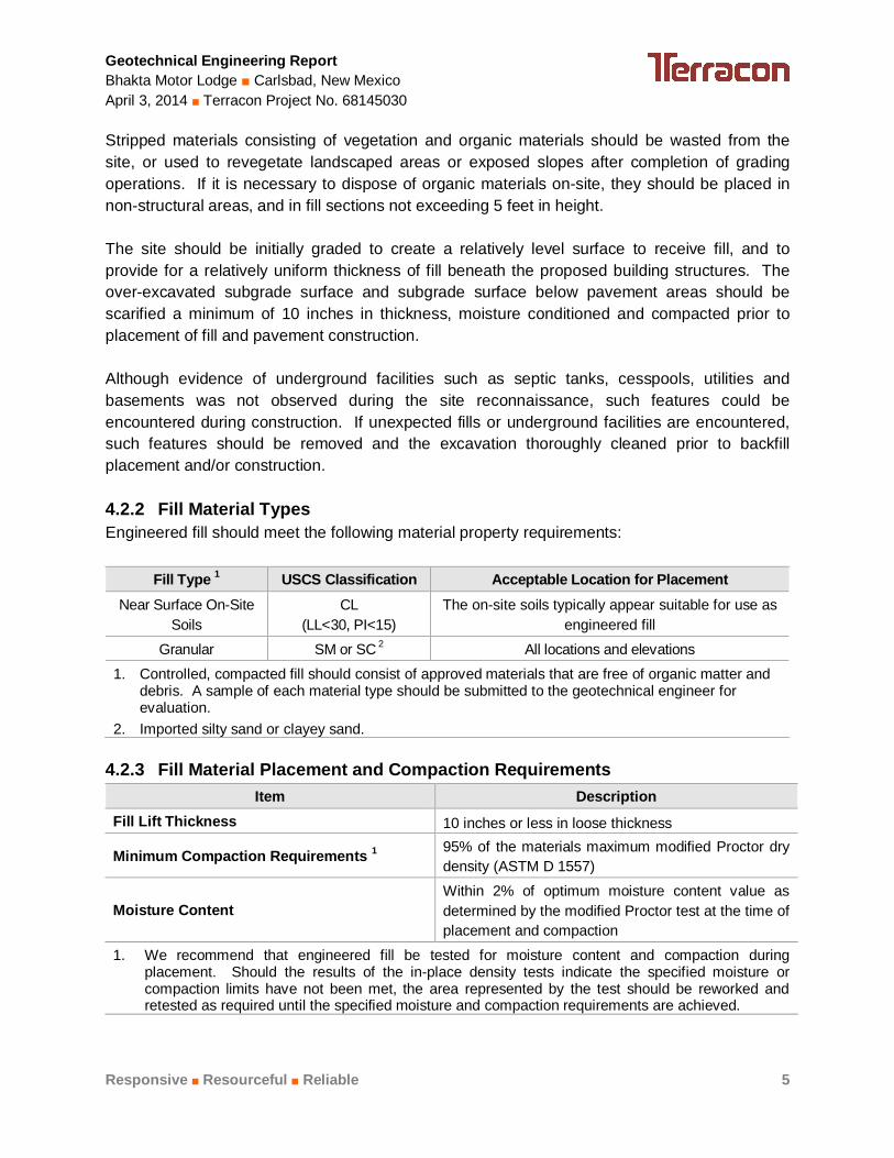
Stripped materials consisting of vegetation and organic materials should be wasted from the site, or used to revegetate landscaped areas or exposed slopes after completion of grading operations. If it is necessary to dispose of organic materials on-site, they should be placed in non-structural areas, and in fill sections not exceeding 5 feet in height. The site should be initially graded to create a relatively level surface to receive fill, and to provide for a relatively uniform thickness of fill beneath the proposed building structures. The over-excavated subgrade surface and subgrade surface below pavement areas should be scarified a minimum of 10 inches in thickness, moisture conditioned and compacted prior to placement of fill and pavement construction. Although evidence of underground facilities such as septic tanks, cesspools, utilities and basements was not observed during the site reconnaissance, such features could be encountered during construction. If unexpected fills or underground facilities are encountered, such features should be removed and the excavation thoroughly cleaned prior to backfill placement and/or construction. 4.2.2 Fill Material Types Engineered fill should meet the following material property requirements:
Fill Type 1 USCS Classification Acceptable Location for Placement Near Surface On-Site
Soils CL
(LL<30, PI<15) The on-site soils typically appear suitable for use as
engineered fill
Granular SM or SC 2 All locations and elevations
1. Controlled, compacted fill should consist of approved materials that are free of organic matter and debris. A sample of each material type should be submitted to the geotechnical engineer for evaluation.
2. Imported silty sand or clayey sand. 4.2.3 Fill Material Placement and Compaction Requirements
Item Description Fill Lift Thickness 10 inches or less in loose thickness
Minimum Compaction Requirements 1 95% of the materials maximum modified Proctor dry density (ASTM D 1557)
Moisture Content Within 2% of optimum moisture content value as determined by the modified Proctor test at the time of placement and compaction
1. We recommend that engineered fill be tested for moisture content and compaction during placement. Should the results of the in-place density tests indicate the specified moisture or compaction limits have not been met, the area represented by the test should be reworked and retested as required until the specified moisture and compaction requirements are achieved.
Geotechnical Engineering Report Bhakta Motor Lodge Carlsbad, New Mexico April 3, 2014 Terracon Project No. 68145030
Responsive Resourceful Reliable 6
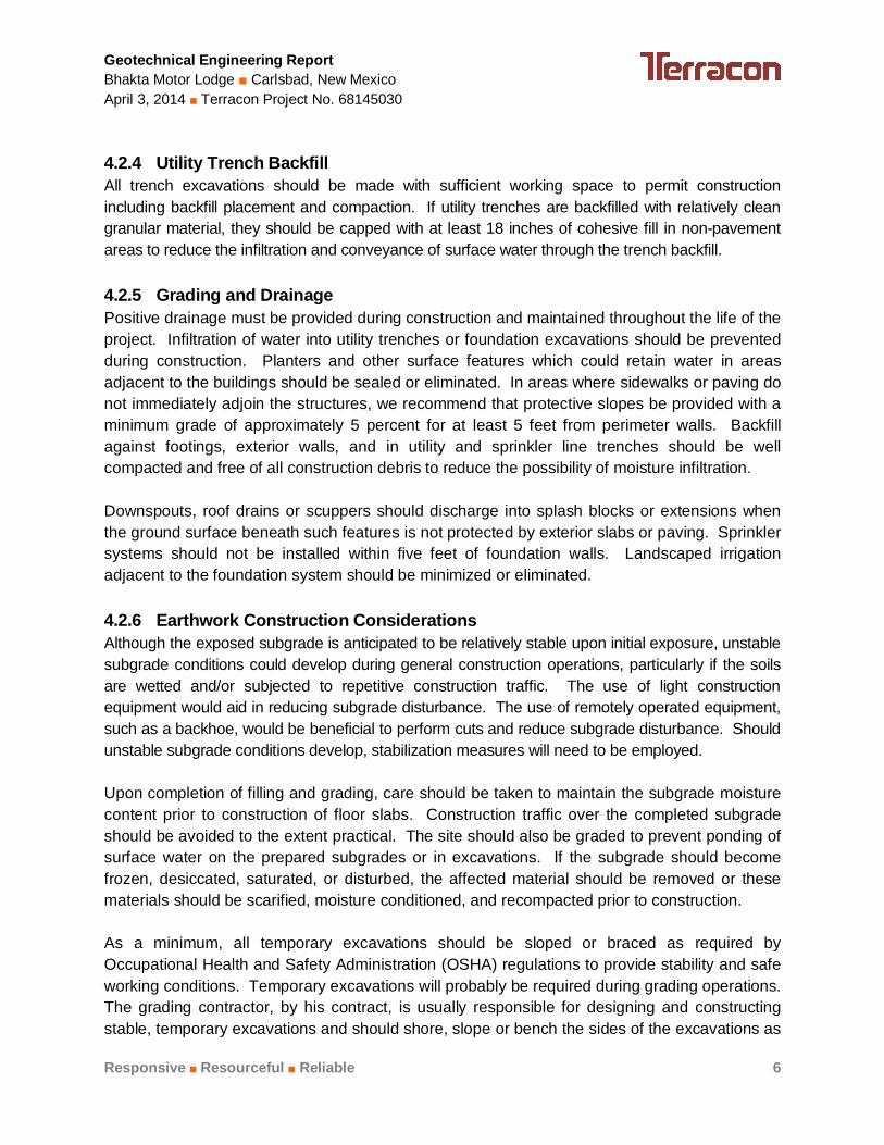
4.2.4 Utility Trench Backfill All trench excavations should be made with sufficient working space to permit construction including backfill placement and compaction. If utility trenches are backfilled with relatively clean granular material, they should be capped with at least 18 inches of cohesive fill in non-pavement areas to reduce the infiltration and conveyance of surface water through the trench backfill. 4.2.5 Grading and Drainage Positive drainage must be provided during construction and maintained throughout the life of the project. Infiltration of water into utility trenches or foundation excavations should be prevented during construction. Planters and other surface features which could retain water in areas adjacent to the buildings should be sealed or eliminated. In areas where sidewalks or paving do not immediately adjoin the structures, we recommend that protective slopes be provided with a minimum grade of approximately 5 percent for at least 5 feet from perimeter walls. Backfill against footings, exterior walls, and in utility and sprinkler line trenches should be well compacted and free of all construction debris to reduce the possibility of moisture infiltration. Downspouts, roof drains or scuppers should discharge into splash blocks or extensions when the ground surface beneath such features is not protected by exterior slabs or paving. Sprinkler systems should not be installed within five feet of foundation walls. Landscaped irrigation adjacent to the foundation system should be minimized or eliminated. 4.2.6 Earthwork Construction Considerations Although the exposed subgrade is anticipated to be relatively stable upon initial exposure, unstable subgrade conditions could develop during general construction operations, particularly if the soils are wetted and/or subjected to repetitive construction traffic. The use of light construction equipment would aid in reducing subgrade disturbance. The use of remotely operated equipment, such as a backhoe, would be beneficial to perform cuts and reduce subgrade disturbance. Should unstable subgrade conditions develop, stabilization measures will need to be employed. Upon completion of filling and grading, care should be taken to maintain the subgrade moisture content prior to construction of floor slabs. Construction traffic over the completed subgrade should be avoided to the extent practical. The site should also be graded to prevent ponding of surface water on the prepared subgrades or in excavations. If the subgrade should become frozen, desiccated, saturated, or disturbed, the affected material should be removed or these materials should be scarified, moisture conditioned, and recompacted prior to construction. As a minimum, all temporary excavations should be sloped or braced as required by Occupational Health and Safety Administration (OSHA) regulations to provide stability and safe working conditions. Temporary excavations will probably be required during grading operations. The grading contractor, by his contract, is usually responsible for designing and constructing stable, temporary excavations and should shore, slope or bench the sides of the excavations as
Geotechnical Engineering Report Bhakta Motor Lodge Carlsbad, New Mexico April 3, 2014 Terracon Project No. 68145030
Responsive Resourceful Reliable 7
required, to maintain stability of both the excavation sides and bottom. All excavations should comply with applicable local, state and federal safety regulations, including the current OSHA Excavation and Trench Safety Standards. The geotechnical engineer should be retained during the construction phase of the project to observe earthwork and to perform necessary tests and observations during subgrade preparation; moisture conditioning; re-compaction; placement and compaction of controlled compacted fills; backfilling of excavations into the completed subgrade, and just prior to construction. 4.3 Foundation Recommendations The structures can be supported by spread and continuous footings. Design recommendations for foundations for the proposed structure and related structural elements are presented in the following paragraphs. 4.3.1 Foundation Design Recommendations
Description Value Foundation Type Spread and Continuous Footings
Bearing Material Minimum of 36 inches of engineered fill underlain by compacted native soils
Finished grade is defined as the lowest adjacent grade within five feet of the foundation for perimeter (or exterior) footings and finished floor level for interior footings. The allowable foundation bearing pressures apply to dead loads plus design live load conditions. The design bearing pressure may be increased by one-third when considering total loads that include wind or seismic conditions. The weight of the foundation concrete below grade may be neglected in dead load computations. Footings should be proportioned to reduce differential foundation movement. Proportioning on the basis of equal total movement is recommended; however, proportioning to relative constant dead-load pressure will also reduce differential movement between adjacent footings. Additional foundation movements could occur if water from any source infiltrates the foundation soils; therefore, proper drainage must be provided in the final design and during construction.
Geotechnical Engineering Report Bhakta Motor Lodge Carlsbad, New Mexico April 3, 2014 Terracon Project No. 68145030
Responsive Resourceful Reliable 8
Footings, foundations and masonry walls (if applicable) should be reinforced as necessary to reduce the potential for distress caused by differential foundation movement. The use of joints at openings or other discontinuities in masonry walls (if applicable) is recommended. Foundation excavations and engineered fill placement should be observed by the geotechnical engineer. If the soil conditions encountered differ significantly from those presented in this report, supplemental recommendations will be required. 4.3.2 Foundation Construction Considerations A minimum of 36 inches of engineered fill is recommended below all footings. The subgrade soils should be removed to a minimum depth of 36 inches and a minimum of 24 inches horizontally beyond the edge of footings. The engineered fill should extend laterally an additional distance of 8 inches for each additional foot of excavation beyond the 36-inch minimum depth. The soils should be replaced with approved engineered fill, conditioned to near optimum moisture content and compacted. 4.4 Seismic Considerations
Description Value 2009 International Building Code Site Classification (IBC) 1 D2
Site Latitude 32.3652 Site Longitude -104.2353
Spectral Response Accelerations SMs and SM1 SMs = FaSs and SM1 = FvS1
Site Class D - Fa = 1.6, Fv = 2.4
SMS Spectral Acceleration for a Short Period (0.2 sec) 0.277g SM1 Spectral Acceleration for a 1-Second Period 0.116g
SDs = 2/3 x SMs and SD1 = 2/3 x SM1 SDS Spectral Acceleration for a Short Period (0.2 sec) 0.185g
SD1 Spectral Acceleration for a 1-Second Period 0.077g 1 Note: In general accordance with the 2009 International Building Code, Table 1613.5.2. 2 Note: The 2009 International Building Code (IBC) requires a site soil profile determination extending to a depth of 100 feet for seismic site classification. The current scope does not include the required 100 foot soil profile determination. The borings extending to a maximum depth of 21-1/2 feet, and this seismic site class definition considers that dense soil may be encountered below the maximum depth of the subsurface exploration. Additional exploration to deeper depths would be required to confirm the conditions below the current depth of exploration.
Geotechnical Engineering Report Bhakta Motor Lodge Carlsbad, New Mexico April 3, 2014 Terracon Project No. 68145030
Interior floor system Slab-on-grade concrete for use with standard spread and continuous footings.
Floor slab support 24 inches of engineered fill soils placed and compacted in accordance with Earthwork section of this report.
Modulus of subgrade reaction 100 pounds per square inch per inch (psi/in) Construction of floor slabs on compacted native subgrade soils or engineered fill composed of approved on-site materials or imported soils is considered acceptable for the project. In areas of exposed concrete, control joints should be saw cut into the slab after concrete placement in accordance with ACI Design Manual, Section 302.1R-37 8.3.12 (tooled control joints are not recommended). Additionally, dowels should be placed at the location of proposed construction joints. To control the width of cracking (should it occur) continuous slab reinforcement should be considered in exposed concrete slabs. Positive separations and/or isolation joints should be provided between slabs and all foundations, columns or utility lines to allow independent movement. Interior trench backfill placed beneath slabs should be compacted in accordance with recommendations outlined in the Earthwork section of this report. Other design and construction considerations, as outlined in the ACI Design Manual, Section 302.1R are recommended. 4.5.2 Floor Slab Construction Considerations A minimum of 24 inches of engineered fill is recommended below slabs-on-grade. The engineered fill should extend horizontally a minimum distance of 5 feet beyond the outside edge of perimeter footings. Some differential movement of a slab-on-grade floor system is possible should the subgrade soils become elevated in moisture content. Such movements are anticipated to be within general tolerance for normal slab-on-grade construction. To reduce potential slab movements, the subgrade soils should be prepared as outlined in the Earthwork section of this report. 4.6 Swimming Pool We assume the proposed project will include construction of a 5-foot deep swimming pool. Difficult excavation of the pool area is not anticipated at this site. Consideration should be given to the use of reinforced gunnite concrete for pool construction. This material can normally withstand relatively large soil movements without cracking.
Geotechnical Engineering Report Bhakta Motor Lodge Carlsbad, New Mexico April 3, 2014 Terracon Project No. 68145030
Responsive Resourceful Reliable 10
The swimming pool should be bedded in a layer of free-draining granular material to provide a solid base for construction. A clean material with a maximum 1-1/2-inch size and a minimum 3/8-inch size is recommended. A reinforced gunnite pool is acceptable for the site, since groundwater should not be an issue.
A drainage system should be provided around the pool. The drain should consist of a minimum six inch layer of clean gravel (minimum 3/4-inch size) beneath the sides of the pool. The gravel layer beneath the pool should be sloped so that it will drain into tiles or perforated drain pipe. The layout of the perforated pipe should include at least one pipe running down the center of the pool lengthwise. Cross-connecting pipes, spanning with the pool, should be placed at six-foot centers. The cross-connecting pipes should be joined to the center pipe with solid "tees" or "cross" connections. The center pipes should be sloped to a positive gravity outlet or sloped to a sump located in the equipment room, permitting pump discharge. The soils that will support pool deck slabs around the pool could settle with increasing moisture content. To reduce possible damage that could be caused by settlement due to compressible soils, we recommend:
over-excavate 12 inches below the deck slabs support deck slabs on prepared native soils or engineered fill with no, or very low
expansion potential strict moisture-density control during placement of subgrade fills placement of effective control joints on relatively close centers and isolation joints
between slabs and other structural elements provision for adequate drainage in areas adjoining the slabs use of designs which allow vertical movement between the deck slabs and adjoining
structural elements Fill, backfill, and surface drainage in the pool area should be placed in accordance with the recommendations in the "Earthwork" section of this report. Grading should be provided for diversion of deck surface runoff away from the pool area. In no case should water be allowed to pond around the slab perimeter. 4.7 Pavements 4.7.1 Design Recommendations Design of pavements for the project has been based on the procedures outlined in the Design of Hot Mix Asphalt Pavements by the National Asphalt Pavement Association (NAPA) and ACI for PCC pavement. Calculated traffic criteria used for pavement thickness design includes single 18-kip equivalent standard axle loads (ESAL's) of 18,000 for planned auto parking areas and 50,000 for heavy vehicle drive areas. Actual design traffic loading should be verified.
Geotechnical Engineering Report Bhakta Motor Lodge Carlsbad, New Mexico April 3, 2014 Terracon Project No. 68145030
Responsive Resourceful Reliable 11
Reevaluation of the recommended pavement sections may be necessary if the actual traffic varies from the assumed criteria outlined above. Recommended alternatives for flexible and rigid pavements, summarized for each traffic area, are as follows:
Each alternative should be investigated with respect to current material availability and economic conditions. Rigid concrete pavement, a minimum of 6 inches in thickness, is recommended at the location of dumpsters where trash trucks will park and load or areas of anticipated heavy vehicle loads. Concrete construction and placement for the parking and drive areas (i.e. curb and gutter, drainage ditches, etc.) should be in accordance with the New Mexico Department of Transportation guidelines. Aggregate base course should be placed in lifts not exceeding six inches and should be compacted to a minimum of 95% Modified Proctor Density (ASTM D1557).
Asphaltic concrete mix designs should be submitted prior to construction to verify their adequacy. Asphalt material should be placed in maximum 3-inch lifts and should be compacted to a minimum of 93% Maximum Theoretical Density (AASHTO T-209).
Future performance of pavements constructed at this site will be dependent upon several factors, including maintaining stable moisture content of the subgrade soils, conditioning of the existing fill and providing for a planned program of preventative maintenance. Recommendations for pavement construction presented depend upon compliance with recommended material specifications. To assess compliance, observation and testing should be performed under the direction of the geotechnical engineer. Pavement design methods are intended to provide structural sections with adequate thickness over a particular subgrade such that wheel loads are reduced to a level the subgrade can support. The support characteristics of the subgrade for pavement design do not account for settlement induced movements of subgrade such as the soils encountered on this project.
Geotechnical Engineering Report Bhakta Motor Lodge Carlsbad, New Mexico April 3, 2014 Terracon Project No. 68145030
Responsive Resourceful Reliable 12
Thus, the pavement may be adequate from a structural standpoint, yet still experience cracking and deformation due to settlement related movement of the subgrade. It is, therefore, important to minimize moisture changes in the subgrade to reduce settlement. Future performance of pavements constructed on the native or engineered fill soils at this site will be dependent upon several factors, including:
maintaining stable moisture content of the subgrade soils. providing for a planned program of preventative maintenance.
Pavements could crack in the future primarily because of settlement of the soils when subjected to an increase in moisture content to the subgrade. The cracking, while not desirable, does not necessarily constitute structural failure of the pavement. The performance of all pavements can be enhanced by minimizing excess moisture which can reach the subgrade soils. The following recommendations should be considered at minimum:
site grading at a minimum 2 percent grade away from the pavements. the subgrade and the pavement surface have a minimum 1/4 inch per foot slope to
promote proper surface drainage. consider appropriate edge drainage and pavement underdrain systems. install pavement drainage surrounding areas anticipated for frequent wetting. install joint sealant and seal cracks immediately. compaction of any utility trenches for landscaped areas to the same criteria as the
pavement subgrade. seal all landscaped areas in or adjacent to pavements to minimize or prevent moisture
migration to subgrade soils. place compacted, low permeability backfill against the exterior side of curb and gutter.
5.0 GENERAL COMMENTS Terracon should be retained to review the final design plans and specifications so comments can be made regarding interpretation and implementation of our geotechnical recommendations in the design and specifications. Terracon also should be retained to provide observation and testing services during grading, excavation, foundation construction and other earth-related construction phases of the project. The analysis and recommendations presented in this report are based upon the data obtained from the borings performed at the indicated locations and from other information discussed in this report. This report does not reflect variations that may occur between borings, across the site, or due to the modifying effects of construction or weather. The nature and extent of such
Geotechnical Engineering Report Bhakta Motor Lodge Carlsbad, New Mexico April 3, 2014 Terracon Project No. 68145030
Responsive Resourceful Reliable 13
variations may not become evident until during or after construction. If variations appear, we should be immediately notified so that further evaluation and supplemental recommendations can be provided. The scope of services for this project does not include either specifically or by implication any environmental or biological (e.g., mold, fungi, bacteria) assessment of the site or identification or prevention of pollutants, hazardous materials or conditions. If the owner is concerned about the potential for such contamination or pollution, other studies should be undertaken. This report has been prepared for the exclusive use of our client for specific application to the project discussed and has been prepared in accordance with generally accepted geotechnical engineering practices. No warranties, either express or implied, are intended or made. Site safety, excavation support, and dewatering requirements are the responsibility of others. In the event that changes in the nature, design, or location of the project as outlined in this report are planned, the conclusions and recommendations contained in this report shall not be considered valid unless Terracon reviews the changes and either verifies or modifies the conclusions of this report in writing.
APPENDIX A
FIELD EXPLORATION
SITE LOCATION
Bhakta Motor Lodge 4200 National Parks Highway
Carlsbad, NM
TOPOGRAPHIC MAP IMAGE COURTESY OF THE U.S. GEOLOGICAL SURVEY QUADRANGLES INCLUDE: CARLSBAD WEST, NM (1/1/1985), CARLSBAD EAST, NM (1/1/1985), KITCHEN COVE, NM (1/1/1985) and OTIS, NM (1/1/1985).
1640 Hickory Loop Suite 105 Las Cruces, NM
68145030 Project Manager:
Drawn by:
Checked by:
Approved by:
BLB JDC JDC
1:24,000 Site Location
4/1/14
Project No.
Scale:
File Name:
Date:A-1
Exhibit DB
National Parks Highway
Chapman Road
EXPLORATION PLAN
Bhakta Motor Lodge 4200 National Parks Highway
Carlsbad, NM 1640 Hickory Loop Suite 105
Las Cruces, NM
DIAGRAM IS FOR GENERAL LOCATION ONLY, AND IS NOT INTENDED FOR CONSTRUCTION PURPOSES
68145030
AERIAL PHOTOGRAPHY PROVIDED BY MICROSOFT BING MAPS
BLB JDC JDC
AS SHOWN Boring Location
4/1/14
Scale:
A-2
Exhibit Project Manager:
Drawn by:
Checked by:
Approved by:
Project No.
File Name:
Date:
DB
B-2
B-1
B-1
B-3
B-7
B-8
Approximate Boring Locations Approximate Location of Percolation Test
B-6 B-5
B-4
P-1
B-9
Geotechnical Engineering Report Bhakta Motor Lodge Carlsbad, New Mexico April 3, 2014 Terracon Project No. 68145030
Responsive Resourceful Reliable Exhibit A-3
Field Exploration Description A total of nine (9) test borings were drilled at the site on March 19, 2014. The borings were drilled to depths of about 5 to 21-1/2 feet below the ground surface at the approximate locations shown on the attached Site Location Map and Boring Location Plan, Exhibit A-1 and A-2, respectively. Auger refusal was encountered in Borings B-4 and B-5 at depths of 17 and 11 feet due to cobbles. The test borings were located as follows:
Borings Location Depth (feet) B-1 thru B-6 Building Footprint 11 to 21-1/2
B-7 Swimming Pool 10-1/2
B-8 and B-9 Parking and Drive Areas 5 The test borings were advanced with a truck-mounted CME-75 drill rig utilizing 8-inch diameter hollow-stem augers. The borings were located in the field by using the proposed site plan and an aerial photograph of the site, and measuring from existing property lines. The accuracy of boring locations should only be assumed to the level implied by the method used. Lithologic logs of each boring were recorded by the field geologist during the drilling operations. At selected intervals, samples of the subsurface materials were taken by driving split-spoon or ring-barrel samplers. Penetration resistance measurements were obtained by driving the split-spoon and ring-barrel samplers into the subsurface materials with a 140-pound automatic hammer falling 30 inches. The penetration resistance value is a useful index in estimating the consistency or relative density of materials encountered. A CME automatic SPT hammer was used to advance the split-barrel sampler in the borings performed on this site. The effect of the automatic hammer's efficiency has been considered in the interpretation and analysis of the subsurface information for this report. Groundwater conditions were evaluated in the borings at the time of site exploration. One percolation test (designated P-1) was performed in the proposed retention pond area.
Hammer Type: AutomaticStratification lines are approximate. In-situ, the transition may be gradual.
LOCATION
DEPTH
GR
AP
HIC
LO
G
4200 National Parks Highway Carlsbad, New MexicoSITE:
WATER LEVEL OBSERVATIONS
Page 1 of 1
Advancement Method:Hollow Stem Auger
Abandonment Method:Borings backfilled with soil cuttings upon completion.
1640 Hickory Loop, Suite 105Las Cruces, New Mexico
Notes:
Project No.: 68145030
Drill Rig: CME 75
Boring Started: 3/19/2014
BORING LOG NO. B-1Henry BhaktaCLIENT:Clovis, New Mexico
Driller: Tierra Drilling
Boring Completed: 3/19/2014
Exhibit:
No free water observed
A-3
PROJECT: Bhakta Motor Lodge
See Exhibit A-3 for description of fieldprocedures.See Appendix B for description of laboratoryprocedures and additional data (if any).
See Appendix C for explanation of symbols andabbreviations.
TH
IS B
OR
ING
LO
G IS
NO
T V
ALI
D IF
SE
PA
RA
TE
D F
RO
M O
RIG
INA
L R
EP
OR
T.
G
EO
SM
AR
T L
OG
-NO
WE
LL 6
813
503
0.G
PJ
FIE
LD T
ES
TR
ES
ULT
S
TE
ST
TY
PE
CO
MP
RE
SS
IVE
ST
RE
NG
TH
(psf
)
ST
RA
IN (
%)
STRENGTH TEST
PE
RC
EN
T F
INE
S
WA
TE
RC
ON
TE
NT
(%
)
DR
Y U
NIT
WE
IGH
T (
pcf)
ATTERBERGLIMITS
LL-PL-PI
DE
PT
H (
Ft.)
5
10
15
20
WA
TE
R L
EV
EL
OB
SE
RV
AT
ION
S
SA
MP
LE T
YP
E
15.0
21.4
SANDY LEAN CLAY (CL), light brown, soft
stiff
trace gravel, very stiff
SILTY CLAYEY GRAVEL WITH SAND (GC-GM), lightgray, very dense, cobbles
Boring Terminated at 21.417 Feet
3-2-2N=4
1-5-8N=13
7-13-14N=27
50/5"N=50/5"
50/5"N=50/5"
See Exhibit A-2
Hammer Type: AutomaticStratification lines are approximate. In-situ, the transition may be gradual.
LOCATION
DEPTH
GR
AP
HIC
LO
G
4200 National Parks Highway Carlsbad, New MexicoSITE:
WATER LEVEL OBSERVATIONS
Page 1 of 1
Advancement Method:Hollow Stem Auger
Abandonment Method:Borings backfilled with soil cuttings upon completion.
1640 Hickory Loop, Suite 105Las Cruces, New Mexico
Notes:
Project No.: 68145030
Drill Rig: CME 75
Boring Started: 3/19/2014
BORING LOG NO. B-2Henry BhaktaCLIENT:Clovis, New Mexico
Driller: Tierra Drilling
Boring Completed: 3/19/2014
Exhibit:
No free water observed
A-4
PROJECT: Bhakta Motor Lodge
See Exhibit A-3 for description of fieldprocedures.See Appendix B for description of laboratoryprocedures and additional data (if any).
See Appendix C for explanation of symbols andabbreviations.
TH
IS B
OR
ING
LO
G IS
NO
T V
ALI
D IF
SE
PA
RA
TE
D F
RO
M O
RIG
INA
L R
EP
OR
T.
G
EO
SM
AR
T L
OG
-NO
WE
LL 6
813
503
0.G
PJ
FIE
LD T
ES
TR
ES
ULT
S
TE
ST
TY
PE
CO
MP
RE
SS
IVE
ST
RE
NG
TH
(psf
)
ST
RA
IN (
%)
STRENGTH TEST
PE
RC
EN
T F
INE
S
WA
TE
RC
ON
TE
NT
(%
)
DR
Y U
NIT
WE
IGH
T (
pcf)
ATTERBERGLIMITS
LL-PL-PI
DE
PT
H (
Ft.)
5
10
15
20
WA
TE
R L
EV
EL
OB
SE
RV
AT
ION
S
SA
MP
LE T
YP
E
14.0
20.2
SANDY LEAN CLAY (CL), light brown, stiff
hard
trace gravel
SILTY CLAYEY GRAVEL WITH SAND (GC-GM), lightgray, very dense
Boring Terminated at 20.167 Feet
4-5-6N=11
3-12-21N=33
3-10-25N=35
24-50/2"N=50/2"
50/2"N=50/2"
242 21-15-6
See Exhibit A-2
Hammer Type: AutomaticStratification lines are approximate. In-situ, the transition may be gradual.
LOCATION
DEPTH
GR
AP
HIC
LO
G
4200 National Parks Highway Carlsbad, New MexicoSITE:
WATER LEVEL OBSERVATIONS
Page 1 of 1
Advancement Method:Hollow Stem Auger
Abandonment Method:Borings backfilled with soil cuttings upon completion.
1640 Hickory Loop, Suite 105Las Cruces, New Mexico
Notes:
Project No.: 68145030
Drill Rig: CME 75
Boring Started: 3/19/2014
BORING LOG NO. B-3Henry BhaktaCLIENT:Clovis, New Mexico
Driller: Tierra Drilling
Boring Completed: 3/19/2014
Exhibit:
No free water observed
A-5
PROJECT: Bhakta Motor Lodge
See Exhibit A-3 for description of fieldprocedures.See Appendix B for description of laboratoryprocedures and additional data (if any).
See Appendix C for explanation of symbols andabbreviations.
TH
IS B
OR
ING
LO
G IS
NO
T V
ALI
D IF
SE
PA
RA
TE
D F
RO
M O
RIG
INA
L R
EP
OR
T.
G
EO
SM
AR
T L
OG
-NO
WE
LL 6
813
503
0.G
PJ
FIE
LD T
ES
TR
ES
ULT
S
TE
ST
TY
PE
CO
MP
RE
SS
IVE
ST
RE
NG
TH
(psf
)
ST
RA
IN (
%)
STRENGTH TEST
PE
RC
EN
T F
INE
S
WA
TE
RC
ON
TE
NT
(%
)
DR
Y U
NIT
WE
IGH
T (
pcf)
ATTERBERGLIMITS
LL-PL-PI
DE
PT
H (
Ft.)
5
10
15
20
WA
TE
R L
EV
EL
OB
SE
RV
AT
ION
S
SA
MP
LE T
YP
E
15.0
17.0
SANDY LEAN CLAY (CL), light brown, medium stiff
very stiff
CLAYEY SAND WITH GRAVEL (SC), light brown,dense, cobbles
Auger refusal due to cobbles at 17 Feet
2-4-4N=8
21-16
15-7-10N=17
3-21-23N=44
9 96
See Exhibit A-2
Hammer Type: AutomaticStratification lines are approximate. In-situ, the transition may be gradual.
LOCATION
DEPTH
GR
AP
HIC
LO
G
4200 National Parks Highway Carlsbad, New MexicoSITE:
WATER LEVEL OBSERVATIONS
Page 1 of 1
Advancement Method:Hollow Stem Auger
Abandonment Method:Borings backfilled with soil cuttings upon completion.
1640 Hickory Loop, Suite 105Las Cruces, New Mexico
Notes:
Project No.: 68145030
Drill Rig: CME 75
Boring Started: 3/19/2014
BORING LOG NO. B-4Henry BhaktaCLIENT:Clovis, New Mexico
Driller: Tierra Drilling
Boring Completed: 3/19/2014
Exhibit:
No free water observed
A-6
PROJECT: Bhakta Motor Lodge
See Exhibit A-3 for description of fieldprocedures.See Appendix B for description of laboratoryprocedures and additional data (if any).
See Appendix C for explanation of symbols andabbreviations.
TH
IS B
OR
ING
LO
G IS
NO
T V
ALI
D IF
SE
PA
RA
TE
D F
RO
M O
RIG
INA
L R
EP
OR
T.
G
EO
SM
AR
T L
OG
-NO
WE
LL 6
813
503
0.G
PJ
FIE
LD T
ES
TR
ES
ULT
S
TE
ST
TY
PE
CO
MP
RE
SS
IVE
ST
RE
NG
TH
(psf
)
ST
RA
IN (
%)
STRENGTH TEST
PE
RC
EN
T F
INE
S
WA
TE
RC
ON
TE
NT
(%
)
DR
Y U
NIT
WE
IGH
T (
pcf)
ATTERBERGLIMITS
LL-PL-PI
DE
PT
H (
Ft.)
5
10
15
WA
TE
R L
EV
EL
OB
SE
RV
AT
ION
S
SA
MP
LE T
YP
E
10.0
11.0
SANDY LEAN CLAY (CL), light brown, medium stiff
very stiff
SILTY CLAYEY GRAVEL WITH SAND (GC-GM), lightgray, very denseAuger refusal due to cobbles at 11 Feet
2-3-4N=7
8-13-12N=25
33-50/2"N=50/2"
See Exhibit A-2
Hammer Type: AutomaticStratification lines are approximate. In-situ, the transition may be gradual.
LOCATION
DEPTH
GR
AP
HIC
LO
G
4200 National Parks Highway Carlsbad, New MexicoSITE:
WATER LEVEL OBSERVATIONS
Page 1 of 1
Advancement Method:Hollow Stem Auger
Abandonment Method:Borings backfilled with soil cuttings upon completion.
1640 Hickory Loop, Suite 105Las Cruces, New Mexico
Notes:
Project No.: 68145030
Drill Rig: CME 75
Boring Started: 3/19/2014
BORING LOG NO. B-5Henry BhaktaCLIENT:Clovis, New Mexico
Driller: Tierra Drilling
Boring Completed: 3/19/2014
Exhibit:
No free water observed
A-7
PROJECT: Bhakta Motor Lodge
See Exhibit A-3 for description of fieldprocedures.See Appendix B for description of laboratoryprocedures and additional data (if any).
See Appendix C for explanation of symbols andabbreviations.
TH
IS B
OR
ING
LO
G IS
NO
T V
ALI
D IF
SE
PA
RA
TE
D F
RO
M O
RIG
INA
L R
EP
OR
T.
G
EO
SM
AR
T L
OG
-NO
WE
LL 6
813
503
0.G
PJ
FIE
LD T
ES
TR
ES
ULT
S
TE
ST
TY
PE
CO
MP
RE
SS
IVE
ST
RE
NG
TH
(psf
)
ST
RA
IN (
%)
STRENGTH TEST
PE
RC
EN
T F
INE
S
WA
TE
RC
ON
TE
NT
(%
)
DR
Y U
NIT
WE
IGH
T (
pcf)
ATTERBERGLIMITS
LL-PL-PI
DE
PT
H (
Ft.)
5
10
WA
TE
R L
EV
EL
OB
SE
RV
AT
ION
S
SA
MP
LE T
YP
E
10.0
20.2
LEAN CLAY WITH SAND (CL), light brown, soft
very stiff, cobbles
SILTY CLAYEY GRAVEL WITH SAND (GC-GM), lightgray, very dense, cobbles
Boring Terminated at 20.167 Feet
2-2-2N=4
2-9-15N=24
30-50/2"N=50/2"
17-50/2"N=50/2"
50/2"N=50/2"
See Exhibit A-2
Hammer Type: AutomaticStratification lines are approximate. In-situ, the transition may be gradual.
LOCATION
DEPTH
GR
AP
HIC
LO
G
4200 National Parks Highway Carlsbad, New MexicoSITE:
WATER LEVEL OBSERVATIONS
Page 1 of 1
Advancement Method:Hollow Stem Auger
Abandonment Method:Borings backfilled with soil cuttings upon completion.
1640 Hickory Loop, Suite 105Las Cruces, New Mexico
Notes:
Project No.: 68145030
Drill Rig: CME 75
Boring Started: 3/19/2014
BORING LOG NO. B-6Henry BhaktaCLIENT:Clovis, New Mexico
Driller: Tierra Drilling
Boring Completed: 3/19/2014
Exhibit:
No free water observed
A-8
PROJECT: Bhakta Motor Lodge
See Exhibit A-3 for description of fieldprocedures.See Appendix B for description of laboratoryprocedures and additional data (if any).
See Appendix C for explanation of symbols andabbreviations.
TH
IS B
OR
ING
LO
G IS
NO
T V
ALI
D IF
SE
PA
RA
TE
D F
RO
M O
RIG
INA
L R
EP
OR
T.
G
EO
SM
AR
T L
OG
-NO
WE
LL 6
813
503
0.G
PJ
FIE
LD T
ES
TR
ES
ULT
S
TE
ST
TY
PE
CO
MP
RE
SS
IVE
ST
RE
NG
TH
(psf
)
ST
RA
IN (
%)
STRENGTH TEST
PE
RC
EN
T F
INE
S
WA
TE
RC
ON
TE
NT
(%
)
DR
Y U
NIT
WE
IGH
T (
pcf)
ATTERBERGLIMITS
LL-PL-PI
DE
PT
H (
Ft.)
5
10
15
20
WA
TE
R L
EV
EL
OB
SE
RV
AT
ION
S
SA
MP
LE T
YP
E
10.010.2
LEAN CLAY WITH SAND (CL), light brown, stiff
hard
CLAYEY SAND WITH GRAVEL (SC), light brown, verydense, cobblesBoring Terminated at 10.167 Feet
2-4-5N=9
14-19-22N=41
50/2"N=50/2"
819 29-15-14
See Exhibit A-2
Hammer Type: AutomaticStratification lines are approximate. In-situ, the transition may be gradual.
LOCATION
DEPTH
GR
AP
HIC
LO
G
4200 National Parks Highway Carlsbad, New MexicoSITE:
WATER LEVEL OBSERVATIONS
Page 1 of 1
Advancement Method:Hollow Stem Auger
Abandonment Method:Borings backfilled with soil cuttings upon completion.
1640 Hickory Loop, Suite 105Las Cruces, New Mexico
Notes:
Project No.: 68145030
Drill Rig: CME 75
Boring Started: 3/19/2014
BORING LOG NO. B-7Henry BhaktaCLIENT:Clovis, New Mexico
Driller: Tierra Drilling
Boring Completed: 3/19/2014
Exhibit:
No free water observed
A-9
PROJECT: Bhakta Motor Lodge
See Exhibit A-3 for description of fieldprocedures.See Appendix B for description of laboratoryprocedures and additional data (if any).
See Appendix C for explanation of symbols andabbreviations.
TH
IS B
OR
ING
LO
G IS
NO
T V
ALI
D IF
SE
PA
RA
TE
D F
RO
M O
RIG
INA
L R
EP
OR
T.
G
EO
SM
AR
T L
OG
-NO
WE
LL 6
813
503
0.G
PJ
FIE
LD T
ES
TR
ES
ULT
S
TE
ST
TY
PE
CO
MP
RE
SS
IVE
ST
RE
NG
TH
(psf
)
ST
RA
IN (
%)
STRENGTH TEST
PE
RC
EN
T F
INE
S
WA
TE
RC
ON
TE
NT
(%
)
DR
Y U
NIT
WE
IGH
T (
pcf)
ATTERBERGLIMITS
LL-PL-PI
DE
PT
H (
Ft.)
5
10
WA
TE
R L
EV
EL
OB
SE
RV
AT
ION
S
SA
MP
LE T
YP
E
5.0
LEAN CLAY WITH SAND (CL), light brown
Boring Terminated at 5 Feet
See Exhibit A-2
Hammer Type: AutomaticStratification lines are approximate. In-situ, the transition may be gradual.
LOCATION
DEPTH
GR
AP
HIC
LO
G
4200 National Parks Highway Carlsbad, New MexicoSITE:
WATER LEVEL OBSERVATIONS
Page 1 of 1
Advancement Method:Hollow Stem Auger
Abandonment Method:Borings backfilled with soil cuttings upon completion.
1640 Hickory Loop, Suite 105Las Cruces, New Mexico
Notes:
Project No.: 68145030
Drill Rig: CME 75
Boring Started: 3/19/2014
BORING LOG NO. B-8Henry BhaktaCLIENT:Clovis, New Mexico
Driller: Tierra Drilling
Boring Completed: 3/19/2014
Exhibit:
No free water observed
A-10
PROJECT: Bhakta Motor Lodge
See Exhibit A-3 for description of fieldprocedures.See Appendix B for description of laboratoryprocedures and additional data (if any).
See Appendix C for explanation of symbols andabbreviations.
TH
IS B
OR
ING
LO
G IS
NO
T V
ALI
D IF
SE
PA
RA
TE
D F
RO
M O
RIG
INA
L R
EP
OR
T.
G
EO
SM
AR
T L
OG
-NO
WE
LL 6
813
503
0.G
PJ
FIE
LD T
ES
TR
ES
ULT
S
TE
ST
TY
PE
CO
MP
RE
SS
IVE
ST
RE
NG
TH
(psf
)
ST
RA
IN (
%)
STRENGTH TEST
PE
RC
EN
T F
INE
S
WA
TE
RC
ON
TE
NT
(%
)
DR
Y U
NIT
WE
IGH
T (
pcf)
ATTERBERGLIMITS
LL-PL-PI
DE
PT
H (
Ft.)
5
WA
TE
R L
EV
EL
OB
SE
RV
AT
ION
S
SA
MP
LE T
YP
E
5.0
LEAN CLAY WITH SAND (CL), light brown
Boring Terminated at 5 Feet
839 29-17-12
See Exhibit A-2
Hammer Type: AutomaticStratification lines are approximate. In-situ, the transition may be gradual.
LOCATION
DEPTH
GR
AP
HIC
LO
G
4200 National Parks Highway Carlsbad, New MexicoSITE:
WATER LEVEL OBSERVATIONS
Page 1 of 1
Advancement Method:Hollow Stem Auger
Abandonment Method:Borings backfilled with soil cuttings upon completion.
1640 Hickory Loop, Suite 105Las Cruces, New Mexico
Notes:
Project No.: 68145030
Drill Rig: CME 75
Boring Started: 3/19/2014
BORING LOG NO. B-9Henry BhaktaCLIENT:Clovis, New Mexico
Driller: Tierra Drilling
Boring Completed: 3/19/2014
Exhibit:
No free water observed
A-11
PROJECT: Bhakta Motor Lodge
See Exhibit A-3 for description of fieldprocedures.See Appendix B for description of laboratoryprocedures and additional data (if any).
See Appendix C for explanation of symbols andabbreviations.
TH
IS B
OR
ING
LO
G IS
NO
T V
ALI
D IF
SE
PA
RA
TE
D F
RO
M O
RIG
INA
L R
EP
OR
T.
G
EO
SM
AR
T L
OG
-NO
WE
LL 6
813
503
0.G
PJ
FIE
LD T
ES
TR
ES
ULT
S
TE
ST
TY
PE
CO
MP
RE
SS
IVE
ST
RE
NG
TH
(psf
)
ST
RA
IN (
%)
STRENGTH TEST
PE
RC
EN
T F
INE
S
WA
TE
RC
ON
TE
NT
(%
)
DR
Y U
NIT
WE
IGH
T (
pcf)
ATTERBERGLIMITS
LL-PL-PI
DE
PT
H (
Ft.)
5
WA
TE
R L
EV
EL
OB
SE
RV
AT
ION
S
SA
MP
LE T
YP
E
APPENDIX B
LABORATORY TESTING
Geotechnical Engineering Report Bhakta Motor Lodge Carlsbad, New Mexico April 3, 2014 Terracon Project No. 68145030
Responsive Resourceful Reliable Exhibit B-1
Laboratory Testing Samples retrieved during the field exploration were taken to the laboratory for further observation by the project geotechnical engineer and were classified in accordance with the Unified Soil Classification System (USCS) described in Appendix C. At that time, the field descriptions were confirmed or modified as necessary and an applicable laboratory testing program was formulated to determine engineering properties of the subsurface materials. Laboratory tests were conducted on selected soil samples and the test results are presented in this appendix. The laboratory test results were used for the geotechnical engineering analyses, and the development of foundation and earthwork recommendations. Laboratory tests were performed in general accordance with the applicable ASTM, local or other accepted standards. Selected soil samples obtained from the site were tested for the following engineering properties:
Consolidation In-situ Water Content Sieve Analysis
GRAIN SIZE TERMINOLOGYRELATIVE PROPORTIONS OF SAND AND GRAVEL
TraceWithModifier
Standard Penetration orN-Value
Blows/Ft.
Descriptive Term(Consistency)
Loose
Very Stiff
Exhibit C-1
Standard Penetration orN-Value
Blows/Ft.
Ring SamplerBlows/Ft.
Ring SamplerBlows/Ft.
Medium Dense
Dense
Very Dense
0 - 1 < 3
4 - 9 2 - 4 3 - 4
Medium-Stiff 5 - 9
30 - 50
WA
TE
R L
EV
EL
Auger
Shelby Tube
Ring Sampler
Grab Sample
8 - 15
Split Spoon
Macro Core
Rock Core
PLASTICITY DESCRIPTION
Term
< 1515 - 29> 30
Descriptive Term(s)of other constituents
Water InitiallyEncountered
Water Level After aSpecified Period of Time
Major Componentof Sample
Percent ofDry Weight
(More than 50% retained on No. 200 sieve.)Density determined by Standard Penetration Resistance
Includes gravels, sands and silts.
Hard
Very Loose 0 - 3 0 - 6 Very Soft
7 - 18 Soft
10 - 29 19 - 58
59 - 98 Stiff
less than 500
500 to 1,000
1,000 to 2,000
2,000 to 4,000
4,000 to 8,000> 99
LOCATION AND ELEVATION NOTES
SA
MP
LIN
G
FIE
LD
TE
ST
S
(HP)
(T)
(b/f)
(PID)
(OVA)
DESCRIPTION OF SYMBOLS AND ABBREVIATIONS
Descriptive Term(Density)
Non-plasticLowMediumHigh
BouldersCobblesGravelSandSilt or Clay
10 - 18
> 50 15 - 30 19 - 42
> 30 > 42
_
Hand Penetrometer
Torvane
Standard PenetrationTest (blows per foot)
Photo-Ionization Detector
Organic Vapor Analyzer
Water levels indicated on the soil boringlogs are the levels measured in theborehole at the times indicated.Groundwater level variations will occurover time. In low permeability soils,accurate determination of groundwaterlevels is not possible with short termwater level observations.
CONSISTENCY OF FINE-GRAINED SOILS
(50% or more passing the No. 200 sieve.)Consistency determined by laboratory shear strength testing, field
visual-manual procedures or standard penetration resistance
DESCRIPTIVE SOIL CLASSIFICATION
> 8,000
Unless otherwise noted, Latitude and Longitude are approximately determined using a hand-held GPS device. The accuracyof such devices is variable. Surface elevation data annotated with +/- indicates that no actual topographical survey wasconducted to confirm the surface elevation. Instead, the surface elevation was approximately determined from topographicmaps of the area.
Soil classification is based on the Unified Soil Classification System. Coarse Grained Soils have more than 50% of their dryweight retained on a #200 sieve; their principal descriptors are: boulders, cobbles, gravel or sand. Fine Grained Soils haveless than 50% of their dry weight retained on a #200 sieve; they are principally described as clays if they are plastic, andsilts if they are slightly plastic or non-plastic. Major constituents may be added as modifiers and minor constituents may beadded according to the relative proportions based on grain size. In addition to gradation, coarse-grained soils are definedon the basis of their in-place relative density and fine-grained soils on the basis of their consistency.
Plasticity Index
01 - 1011 - 30
> 30
RELATIVE PROPORTIONS OF FINES
Descriptive Term(s)of other constituents
Percent ofDry Weight
< 55 - 12> 12
No Recovery
RELATIVE DENSITY OF COARSE-GRAINED SOILS
Particle Size
Over 12 in. (300 mm)12 in. to 3 in. (300mm to 75mm)3 in. to #4 sieve (75mm to 4.75 mm)#4 to #200 sieve (4.75mm to 0.075mmPassing #200 sieve (0.075mm)
ST
RE
NG
TH
TE
RM
S Unconfined CompressiveStrength, Qu, psf
4 - 8
GENERAL NOTES
Exhibit C-2
UNIFIED SOIL CLASSIFICATION SYSTEM
Criteria for Assigning Group Symbols and Group Names Using Laboratory Tests A
Soil Classification
Group
Symbol Group Name
B
Coarse Grained Soils:
More than 50% retained
on No. 200 sieve
Gravels:
More than 50% of
coarse fraction retained
on No. 4 sieve
Clean Gravels:
Less than 5% fines C
Cu 4 and 1 Cc 3 E
GW Well-graded gravel F
Cu 4 and/or 1 Cc 3 E
GP Poorly graded gravel F
Gravels with Fines:
More than 12% fines C
Fines classify as ML or MH GM Silty gravel F,G,H
Fines classify as CL or CH GC Clayey gravel F,G,H
Sands:
50% or more of coarse
fraction passes No. 4
sieve
Clean Sands:
Less than 5% fines D
Cu 6 and 1 Cc 3 E
SW Well-graded sand I
Cu 6 and/or 1 Cc 3 E
SP Poorly graded sand I
Sands with Fines:
More than 12% fines D
Fines classify as ML or MH SM Silty sand G,H,I
Fines classify as CL or CH SC Clayey sand G,H,I
Fine-Grained Soils:
50% or more passes the
No. 200 sieve
Silts and Clays:
Liquid limit less than 50
Inorganic: PI 7 and plots on or above “A” line
J CL Lean clay
K,L,M
PI 4 or plots below “A” line J ML Silt
K,L,M
Organic: Liquid limit - oven dried
0.75 OL Organic clay
K,L,M,N
Liquid limit - not dried Organic silt K,L,M,O
Silts and Clays:
Liquid limit 50 or more
Inorganic: PI plots on or above “A” line CH Fat clay
K,L,M
PI plots below “A” line MH Elastic Silt K,L,M
Organic: Liquid limit - oven dried
0.75 OH Organic clay
K,L,M,P
Liquid limit - not dried Organic silt K,L,M,Q
Highly organic soils: Primarily organic matter, dark in color, and organic odor PT Peat
A Based on the material passing the 3-inch (75-mm) sieve
B If field sample contained cobbles or boulders, or both, add “with cobbles
or boulders, or both” to group name. C
Gravels with 5 to 12% fines require dual symbols: GW-GM well-graded
gravel with silt, GW-GC well-graded gravel with clay, GP-GM poorly
graded gravel with silt, GP-GC poorly graded gravel with clay. D
Sands with 5 to 12% fines require dual symbols: SW-SM well-graded
sand with silt, SW-SC well-graded sand with clay, SP-SM poorly graded
sand with silt, SP-SC poorly graded sand with clay
E Cu = D60/D10 Cc =
6010
2
30
DxD
)(D
F If soil contains 15% sand, add “with sand” to group name.
G If fines classify as CL-ML, use dual symbol GC-GM, or SC-SM.
H If fines are organic, add “with organic fines” to group name.
I If soil contains 15% gravel, add “with gravel” to group name.
J If Atterberg limits plot in shaded area, soil is a CL-ML, silty clay.
K If soil contains 15 to 29% plus No. 200, add “with sand” or “with gravel,”
whichever is predominant. L
If soil contains 30% plus No. 200 predominantly sand, add “sandy” to
group name. M
If soil contains 30% plus No. 200, predominantly gravel, add