July 2012 Geotechnical Investigation Mill of Kintail Bridge Reconstruction Town of Mississippi Mills, Ontario Reference No. 60158.005 Prepared for: Town of Mississippi Mills 3131 Old Perth Road Almonte, ON K0A 1A0 Attention: Mr. Cory Smith By: AME Materials Engineering 104 - 215 Stafford Road West Ottawa, ON K2H 9C1 Distribution: 3 copies – Town of Mississippi Mills 1 copy – AME Materials Engineering
Transcript
July 2012
Geotechnical Investigation Mill of Kintail Bridge Reconstruction
Town of Mississippi Mills, Ontario
Reference No. 60158.005 Prepared for: Town of Mississippi Mills 3131 Old Perth Road Almonte, ON K0A 1A0 Attention: Mr. Cory Smith By: AME Materials Engineering 104 - 215 Stafford Road West Ottawa, ON K2H 9C1 Distribution: 3 copies – Town of Mississippi Mills 1 copy – AME Materials Engineering
Specialists in Geotechnical, Environmental and Materials Engineering and Testing
Report No. 60158.005 July 25, 2012 Town of Mississippi Mills 3131 Old Perth Road Almonte, ON K0A 1A0 Attn: Mr. Cory Smith Re: GEOTECHNICAL INVESTIGATION
MILL OF KINTAIL BRIDGE REPLACEMENT TOWNSHIP OF MISSISSIPPI MILLS, ONTARIO
Dear Mr. Smith:
Please find attached our geotechnical report for the above mentioned project.
We trust that this report provides sufficient information for your purposes. If you have any questions
concerning this report, please do not hesitate to contact us.
Sincerely,
AME MATERIALS ENGINEERING
Steve Goodman, Ph.D., P.Eng.
Branch Manager
Geotechnical Investigation – Report No. 60158.005 Mill of Kintail Bridge Reconstruction, Township of Mississippi Mills, Ontario
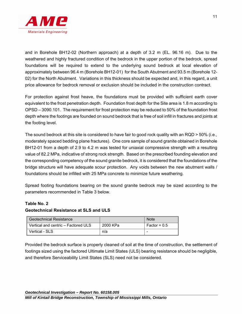
Provided the bedrock surface is properly cleaned of soil at the time of construction, the settlement of
footings sized using the factored Ultimate Limit States (ULS) bearing resistance should be negligible,
and therefore Serviceability Limit States (SLS) need not be considered.
Geotechnical Investigation – Report No. 60158.005 Mill of Kintail Bridge Reconstruction, Township of Mississippi Mills, Ontario
12
The geotechnical bearing resistance provided herein is given under the assumption that the loads will
be applied perpendicular to the surface of the footings. Where the load is not applied perpendicular to
the surface of the footing, inclination of the load should be taken into account in accordance with
Section 6.7.4 of the CHBDC.
The above recommended bearing resistance for foundation design is subject to verification by the Geotechnical Engineer by field inspection of the excavated foundation bases at the time of construction. This is to ensure that the founding soils or bedrock exposed at the excavation base are consistent with the design bearing resistance values intended by the Geotechnical Engineer.
Prior to pouring concrete for the foundations, all footing areas must be cleaned to remove all loose, fractured rock to expose sound, intact bedrock prior to placement of formwork and concrete. If construction proceeds during freezing weather conditions, adequate temporary frost protection for the footing base and concrete must be provided. The rock bearing surface should be inspected by qualified geotechnical personnel. It is critical that the bearing surface is clear of any debris and the method of concrete placement is pre-approved in order to ensure good contact between concrete and bedrock.
Resistance to lateral forces / sliding resistance between the concrete footings and bedrock should be
calculated in accordance with Section 6.7.5 of the CHBDC. The coefficient of friction, tan δ, may be
taken as 0.7 for cast-in-place concrete footings constructed on bedrock. This represents an unfactored
value; in accordance with the CHBDC, a resistance factor of 0.8 is to be applied in calculating the
horizontal resistance. The resistance to lateral loading could be increased by keying or dowelling the
footings into bedrock.
Given the weathered nature of the upper bedrock and the potential for disturbance due to excavating
and blasting, the weathered bedrock should not be considered for lateral resistance. Rock anchors
should be considered for uplift and overturning resistance.
6.5. SITE COEFFICIENT
For seismic design purposes, the Site Coefficient, S, for this site in accordance with Section 4.4.6
of the CHBDC may be taken as 1.0, consistent with Soil Profile Type I.
Geotechnical Investigation – Report No. 60158.005 Mill of Kintail Bridge Reconstruction, Township of Mississippi Mills, Ontario
13
6.6. LATERAL EARTH PRESSURES FOR DESIGN
The lateral earth pressures acting on the bridge abutments will depend on the type and method of
placement of the backfill materials, the nature of the soils behind the backfill, and the magnitude of
surcharge including construction loadings, the freedom of lateral movement of the structure, and the
drainage conditions behind the walls. Seismic (earthquake) loading must also be taken into account in
the design.
The following recommendations are made concerning the design of the abutment stems and retaining
walls in accordance with the CHBDC:
Select free-draining granular fill meeting the specifications of OPSS Granular ‘A’ or Granular ‘B’
Type II but with less than 5 percent passing the No. 200 sieve should be used as backfill behind
the wall. This fill should be compacted in accordance with OPSS 501.
Longitudinal drains and weep holes should be installed to provide positive drainage of the granular
backfill. Other aspects of the granular backfill requirements with respect to subdrains and frost
tapers should be in accordance with OPSD 3101.150, 3190.100, and 3121.150. The outlets for
these subdrains should not be subject to freezing or flooding.
A minimum compaction surcharge of 12 kPa should be included in the lateral earth pressures for
the structure design of the walls, in accordance with CHBDC Section 6.9.3 and Figure 6.6. Care
must be taken during the compaction operation not to overstress the wall. Heavy construction
equipment should be maintained at a distance of at least 1 meter away from walls where the
backfill soils are being placed. Hand-operated compaction equipment should be used to compact
the backfill soils within a 1.0 metre wide zone adjacent to the walls. Other surcharge loadings
should be accounted for in the design, as required.
The granular fill may be placed in a zone with width equal to at least 1.8 metres behind the back of
the abutment stem (Case (a) on Figure C6.20 of the Commentary to the CHBDC) or within the
wedge-shaped zone define by a line drawn at 1.5H:1.0V extending up and back from the rear face
of the footing (Case(b) on Figure C6.20 of the Commentary to the CHBDC).
Geotechnical Investigation – Report No. 60158.005 Mill of Kintail Bridge Reconstruction, Township of Mississippi Mills, Ontario
14
It is not recommended to re-use the silty clay fill with cobbles and boulders described in Section 5.4 since
it is often subject to excessive frost action and swelling when used as wall backfill. The silty gravelly sand
fill and native silty sand till as described in sections 5.3 and 5.5 are generally not recommended for wall
backfill.
Earth pressures acting on the abutment walls should be computed in accordance with Clause 6.9 of the
CHBDC but generally is given by the expression:
P = K [ γ (h-hw) + γ’hw + q ] + γwhw
where,
P = lateral pressure in kPa acting a depth h (m) below ground surface K = applicable lateral earth pressure coefficient h = depth below top of fill where pressure is computed in metres hw = depth below the groundwater level at point of interest (m) γ = bulk unit weight of backfill (kN / m3) γ’ = the submerged unit weight (kN / m3) of exterior soil ( γ’ = γ - γw ) γw = unit weight of water, assume a value of 9.8 kN/m3 q = the complete surcharge loading (kPa)
Where the abutment walls can be drained effectively to eliminate hydrostatic pressure on the wall, this
equation can be simplified to:
P = K [ γh + q ]
where, K = coefficient of lateral earth pressure = unit weight of soil h = height at any point along the wall in metres q = any surcharge load in kPa
Geotechnical Investigation – Report No. 60158.005 Mill of Kintail Bridge Reconstruction, Township of Mississippi Mills, Ontario
15
Static Lateral Earth Pressures for Design: The following guidelines and recommendations are provided regarding the lateral earth pressures for
static (i.e., not earthquake) loading conditions:
For the existing materials (Case (a)), the following unfactored lateral earth pressure parameters
may be used based on the retaining of the existing silty clay fill, silty gravelly sand fill and native
silty sand till deposit for this site:
Material Silty Clay Fill Silty Gravelly Sand Fill Silty Sand Till
Coefficients of static lateral earth pressure: Active, Ka At rest, Ko
Passive, Kp
0.36 0.53 2.77
0.35 0.52 2.88
0.31 0.47 3.26
For Case (b), the pressures are based on granular fill materials as placed and the following
unfactored parameters may be assumed:
Material Granular ‘A’ Granular ‘B’ Type II
Soil Unit Weight 22.8 kN / m3 22.8 kN / m3
Coefficients of static lateral earth pressure: Active, Ka At rest, Ko
Passive, Kp
0.27 0.43 3.70
0.27 0.43 3.70
Seismic Lateral Earth Pressure for Design: Seismic (earthquake) loading must be taken into account in the design in accordance with Section 4.6 of
the CHBDC. In this regard, the following should be included in the assessment of lateral earth pressures:
Geotechnical Investigation – Report No. 60158.005 Mill of Kintail Bridge Reconstruction, Township of Mississippi Mills, Ontario
16
Seismic loading will result in increased lateral pressures acting on the abutment stem. The walls
should be designed to withstand the combined lateral loading for the appropriate static pressure
conditions given above, plus the earthquake-induce dynamic earth pressure. The site-specific
zonal acceleration for the Ottawa area is 0.2. Based on experience, for the subsurface conditions
at this site, no significant amplification of the ground motion is expected. The seismic lateral earth
pressure coefficients given below have been derived based on a design zonal acceleration ratio of
A = 0.2.
In accordance with Sections 4.6.4 and C.4.6.4 of the CHBDC and its Commentary, for structures
which do not allow lateral yielding, the horizontal seismic coefficient, kh, used in the calculation of
the seismic active pressure coefficient is take as 1.5 times the zonal acceleration ration (i.e., kh =
0.3). For structures which allow lateral yielding, kh is taken as 0.5 times the zonal acceleration
ratio (i.e., kh = 0.1).
The following seismic active pressure coefficients (KAE) for the two backfill cases (Case (a) and Case (b))
may be used in design. It should be noted that these seismic earth pressure coefficients assume that the
back of the wall is vertical and the ground surface behind the wall is horizontal. Where sloping ground is
present above the top of the wall, the lateral earth pressure under seismic loading conditions should be
calculated by treating the weight of the backfill located above the top of the wall as a surcharge.
Seismic Active Pressure Coefficients, KAE:
Material Case (a) Case (b)
Silty Clay Fill Silty Gravelly Sand Fill Silty Sand Till Granular ‘A’ Granular ‘B’
Yielding wall 0.39 0.38 0.34 0.30 0.30
Non-yielding wall 0.60 0.59 0.54 0.50 0.50
The above KAE values for yielding wall are applicable provided the wall can move up to 250A
(millimetres), where A is the design zonal acceleration ratio of 0.2. This corresponds to
displacements of up to approximately 50 millimetres at this site.
Geotechnical Investigation – Report No. 60158.005 Mill of Kintail Bridge Reconstruction, Township of Mississippi Mills, Ontario
17
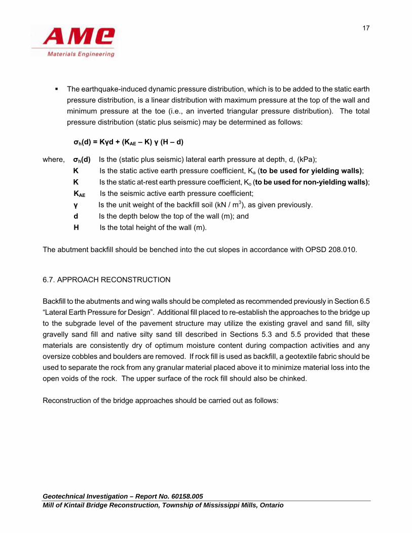
The earthquake-induced dynamic pressure distribution, which is to be added to the static earth
pressure distribution, is a linear distribution with maximum pressure at the top of the wall and
minimum pressure at the toe (i.e., an inverted triangular pressure distribution). The total
pressure distribution (static plus seismic) may be determined as follows:
σh(d) = Kγd + (KAE – K) γ (H – d)
where, σh(d) Is the (static plus seismic) lateral earth pressure at depth, d, (kPa);
K Is the static active earth pressure coefficient, Ka (to be used for yielding walls);
K Is the static at-rest earth pressure coefficient, Ko (to be used for non-yielding walls);
KAE Is the seismic active earth pressure coefficient;
γ Is the unit weight of the backfill soil (kN / m3), as given previously.
d Is the depth below the top of the wall (m); and
H Is the total height of the wall (m).
The abutment backfill should be benched into the cut slopes in accordance with OPSD 208.010.
6.7. APPROACH RECONSTRUCTION
Backfill to the abutments and wing walls should be completed as recommended previously in Section 6.5
“Lateral Earth Pressure for Design”. Additional fill placed to re-establish the approaches to the bridge up
to the subgrade level of the pavement structure may utilize the existing gravel and sand fill, silty
gravelly sand fill and native silty sand till described in Sections 5.3 and 5.5 provided that these
materials are consistently dry of optimum moisture content during compaction activities and any
oversize cobbles and boulders are removed. If rock fill is used as backfill, a geotextile fabric should be
used to separate the rock from any granular material placed above it to minimize material loss into the
open voids of the rock. The upper surface of the rock fill should also be chinked.
Reconstruction of the bridge approaches should be carried out as follows:
Geotechnical Investigation – Report No. 60158.005 Mill of Kintail Bridge Reconstruction, Township of Mississippi Mills, Ontario
18
Remove the native soils and existing fill materials behind the abutment walls within a wedge-
shaped zone extending from 1.2 m behind the base of the abutments and rising upward at an
inclination of 1.0 vertical to 1.5 horizontal, according to OPSD 3101.150.
Further excavate beyond the foundation backfill zone for a frost taper as prescribed by OPSD
3101.150.
Inspect the exposed subsoil checking for any areas of soft material. Remove all areas of soft and
weak material and replace with suitable granular fill compacted to 98% of SPMDD. Replacement
granular fill should consist of OPSS Granular ‘B’Type II.
Place OPSS Granular ‘B’ Type II in thin loose lifts (not exceeding 200 mm thickness) and compact
to 98% of SPMDD within the foundation backfill zone and frost taper.
Place and compact additional fill as required to re-establish the approaches to the bridge up to
the subgrade level of the pavement structure. The existing sand and gravel fill and native silty
sand described in sections 5.3 and 5.5 excavated from the site may be used for this purpose,
provided any oversize cobbles and boulders are excluded from the fill and the material is
consistently dry of optimum moisture content. The fill should be placed in thin loose lifts not
exceeding 200 mm in thickness and compacted to 98% of SPMDD.
The fill placement and compaction operations should be monitored and compaction testing
performed by qualified geotechnical engineering technicians to confirm compliance to project
specifications, and recommendations provided herein.
The backfilling and reconstruction of the bridge approaches should take place under favourable
climatic conditions. If the work is carried out in months where freezing temperatures may occur,
all frost affected material must be removed prior to the placement of frost-free fill.
The pavement structure of the bridge approaches should match the existing, adjacent conditions, or
comply with the engineering standards for the Town of Mississippi Mills.
Geotechnical Investigation – Report No. 60158.005 Mill of Kintail Bridge Reconstruction, Township of Mississippi Mills, Ontario
19
7.0 GENERAL RECOMMENDATIONS
7.1. SITE INSPECTIONS
It is recommended that all footing excavations be inspected and approved by qualified geotechnical
engineering personnel to ensure that the founding bedrock conditions correspond to those encountered in
the boreholes, that footings are placed within the correct strata and that all excavations are dry and free of
loosened, fracture and any otherwise deleterious materials. All backfilling operations should also be
supervised to ensure that proper material is employed and that the specified compaction is achieved.
7.2. WINTER CONDITIONS
In the event of construction during freezing temperatures, the founding stratum should be protected from
freezing by the use of loose straw, tarpaulins, propane heaters or other suitable means. In this regard, the
base of the excavations should be insulated from sub-zero temperatures immediately upon exposure and
until such time the footings are protected with sufficient soil cover to prevent freezing at the founding level.
deanl
Typewritten Text
20
deanl
Typewritten Text
deanl
Typewritten Text
Geotechnical Investigation – Report No. 60158.005 Mill of Kintail Bridge Reconstruction, Township of Mississippi Mills, Ontario
APPENDIX 1
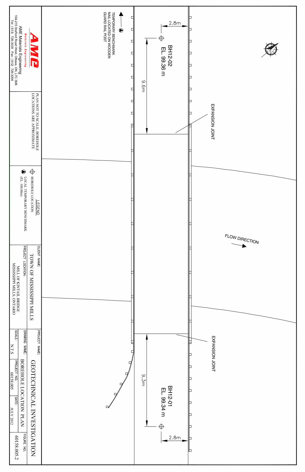
Site Location Plan
Drawing No. 60158.005.1
Borehole Location Plan
Drawing No. 60158.005.2
Geotechnical Investigation – Report No. 60158.005 Mill of Kintail Bridge Reconstruction, Township of Mississippi Mills, Ontario
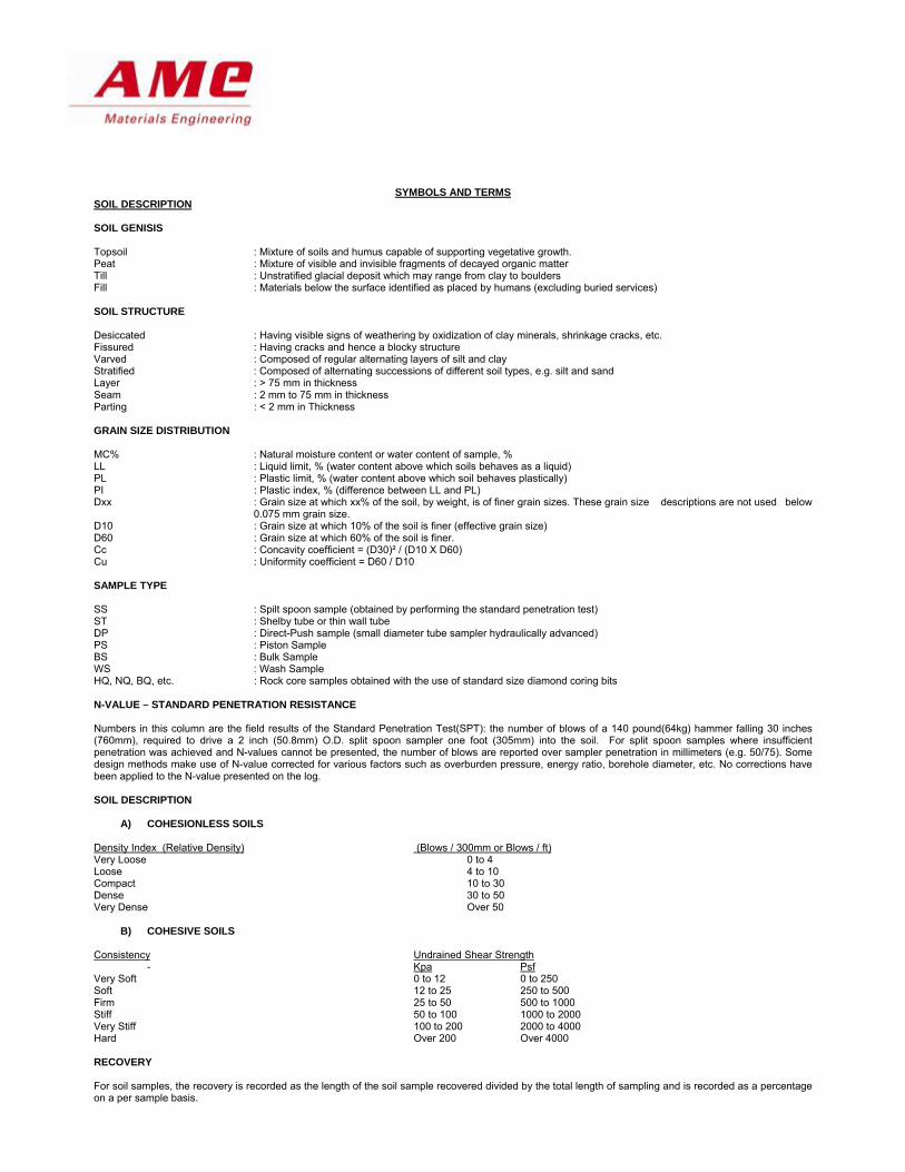
APPENDIX 2
Symbols and Terms
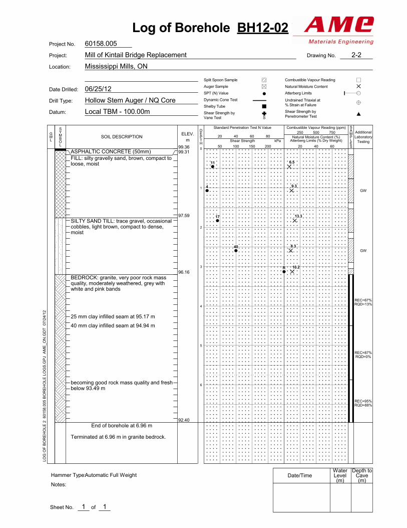
Logs of Boreholes
(BH12-01 to BH12–02)
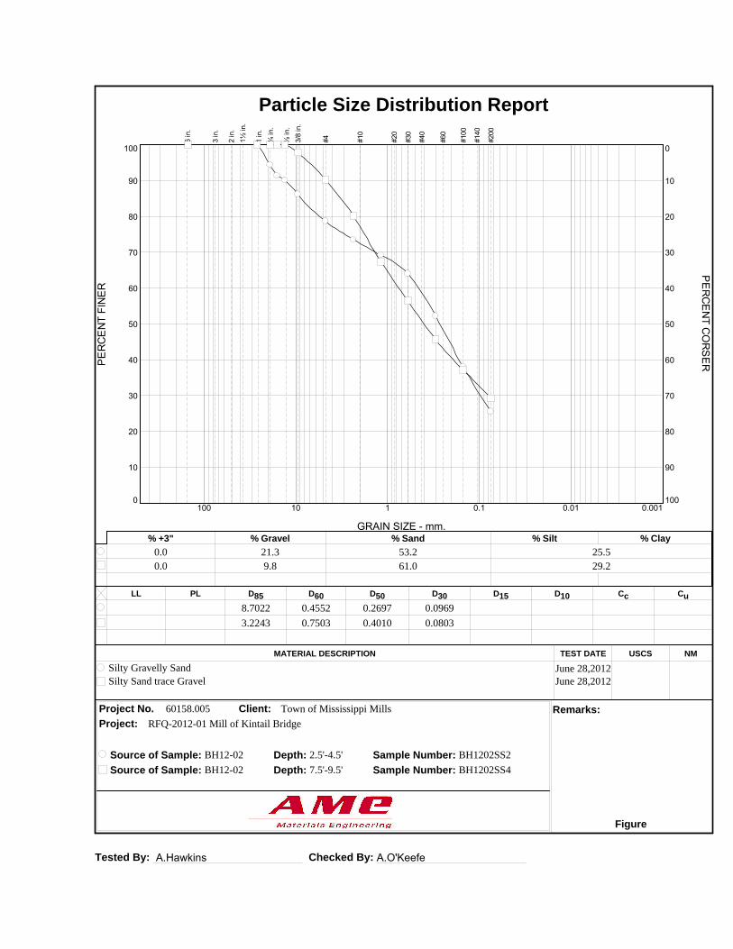
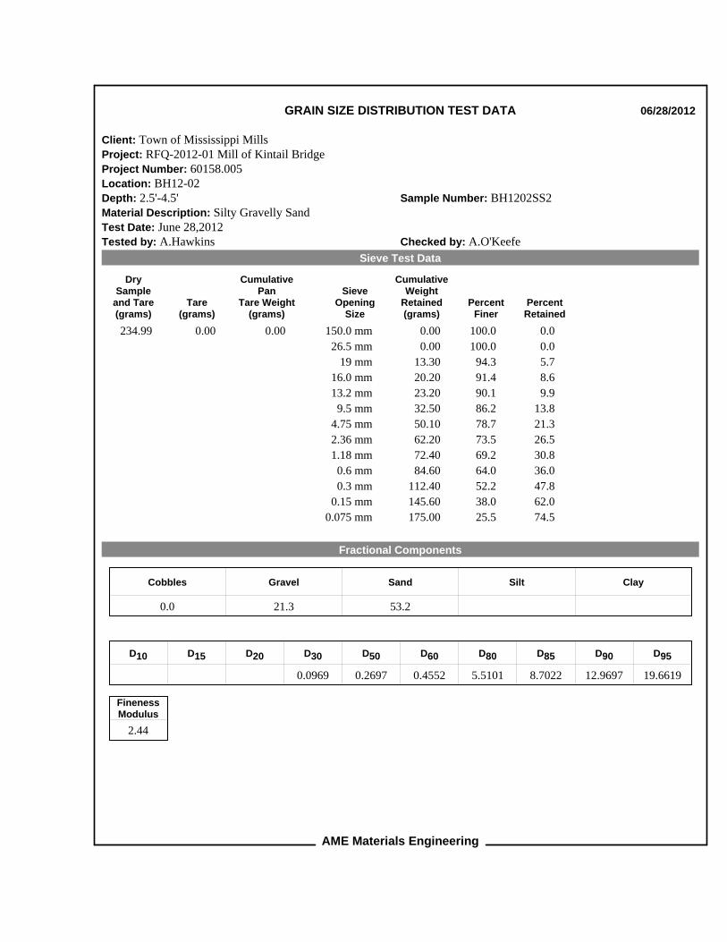
SYMBOLS AND TERMS SOIL DESCRIPTION SOIL GENISIS Topsoil : Mixture of soils and humus capable of supporting vegetative growth. Peat : Mixture of visible and invisible fragments of decayed organic matter Till : Unstratified glacial deposit which may range from clay to boulders Fill : Materials below the surface identified as placed by humans (excluding buried services) SOIL STRUCTURE Desiccated : Having visible signs of weathering by oxidization of clay minerals, shrinkage cracks, etc. Fissured : Having cracks and hence a blocky structure Varved : Composed of regular alternating layers of silt and clay Stratified : Composed of alternating successions of different soil types, e.g. silt and sand Layer : > 75 mm in thickness Seam : 2 mm to 75 mm in thickness Parting : < 2 mm in Thickness GRAIN SIZE DISTRIBUTION MC% : Natural moisture content or water content of sample, % LL : Liquid limit, % (water content above which soils behaves as a liquid) PL : Plastic limit, % (water content above which soil behaves plastically) PI : Plastic index, % (difference between LL and PL) Dxx : Grain size at which xx% of the soil, by weight, is of finer grain sizes. These grain size descriptions are not used below
0.075 mm grain size. D10 : Grain size at which 10% of the soil is finer (effective grain size) D60 : Grain size at which 60% of the soil is finer. Cc : Concavity coefficient = (D30)² / (D10 X D60) Cu : Uniformity coefficient = D60 / D10 SAMPLE TYPE SS : Spilt spoon sample (obtained by performing the standard penetration test) ST : Shelby tube or thin wall tube DP : Direct-Push sample (small diameter tube sampler hydraulically advanced) PS : Piston Sample BS : Bulk Sample WS : Wash Sample HQ, NQ, BQ, etc. : Rock core samples obtained with the use of standard size diamond coring bits N-VALUE – STANDARD PENETRATION RESISTANCE Numbers in this column are the field results of the Standard Penetration Test(SPT): the number of blows of a 140 pound(64kg) hammer falling 30 inches (760mm), required to drive a 2 inch (50.8mm) O.D. split spoon sampler one foot (305mm) into the soil. For split spoon samples where insufficient penetration was achieved and N-values cannot be presented, the number of blows are reported over sampler penetration in millimeters (e.g. 50/75). Some design methods make use of N-value corrected for various factors such as overburden pressure, energy ratio, borehole diameter, etc. No corrections have been applied to the N-value presented on the log. SOIL DESCRIPTION
A) COHESIONLESS SOILS Density Index (Relative Density) (Blows / 300mm or Blows / ft) Very Loose 0 to 4 Loose 4 to 10 Compact 10 to 30 Dense 30 to 50 Very Dense Over 50
B) COHESIVE SOILS Consistency Undrained Shear Strength
- Kpa Psf Very Soft 0 to 12 0 to 250 Soft 12 to 25 250 to 500 Firm 25 to 50 500 to 1000 Stiff 50 to 100 1000 to 2000 Very Stiff 100 to 200 2000 to 4000 Hard Over 200 Over 4000 RECOVERY For soil samples, the recovery is recorded as the length of the soil sample recovered divided by the total length of sampling and is recorded as a percentage on a per sample basis.
SYMBOLS AND TERMS (CONT’D) DYNAMIC CONE PENETRATION TEST (DCPT) Dynamic cone penetration tests are performed using a standard 60 degree apex cone connected to A size drill rods with the same standard fall height and weight as the standard penetration test. The DCPT is used as a probe to assess soil variability. CONSOLIDATION TEST P’ο : Present effective overburden pressure at sample depth. P’с : Preconsolidation pressure of (maximum past pressure on) sample. Ccr : Recompression index (in effect at pressures below P’c) Cc : Compression index (in effect at pressures above P’c) OC ratio : Overconsolidation retio = P’c / P’o Void Ratio : Initial sample void retio = Volume of Voids / Volume of solids Wo : Initial water content (at start of consolidation test) ROCK DESCRIPTION ROCK WEATHERING Term Description Fresh : No Visible signs of rock weathering. Slight discoloration along major discontinuities. Slightly Weathered : Discoloration indicates weathering of rock on discontinuity surfaces. All the rock material may be discolored. Moderately Weathered : Less than half the rock is decomposed and/or disintegrated into the soil. Highly Weathered : More than half the rock is decomposed and/or disintegrated into the soil. Completely Weathered : All the rock material is decomposed and/or disintegrated into the soil. The original mass structure is still largely intact. ROCK MASS: Spacing (mm) Joint Classification Bedding, Laminates, Bands > 6000 Extremely Wide - 2000 – 6000 Very Wide Very Thick 600 – 2000 Wide Thick 200 - 600 Moderate Medium 60 – 200 Close Thin 20 – 60 Very Close Very Thin < 20 Extremely Close Laminated < 6 - Thinly Laminated CORE CONDITION Total Core Recovery (TCR): The percentage of solid drill core recovered regardless of quality or length, measured relative to the length of the total core run Solid Core Recovery (SCR): The percentage of solid drill core, regardless the length, recovered at the full diameter, measure relative to the length of the total core run. Rock Quality Designation (RQD): Rock quality classification is based on a modified core recovery percentage (Rock Quality Designation) RQD in which all pieces of sound core over 100mm long are counted as recovery. The smaller pieces are considered to be due to close shearing, jointing, faulting or weathering in the mass and are not counted. RQD was originally intended to be done on NW core; however it can be used on different core sizes if the bulk of the fractures caused by drilling stresses are easily distinguishable from in situ fractures. The terminology describing rock mass quality based on RQD is subjective and is underlain by the resumption that sound strong rock is of higher engineering value than fractured weak rock. ROCK QUALITY RQD Rock Mass Quality 0 to 25 Very Poor 25 to 50 Poor 50 to 75 Fair 75 to 90 Good 90 to 100 Excellent ROCK STRENGTH Strength Classification Unconfined Compressive Strength (MPa) Extremely Weak < 1 Very Weak 1 – 5 Weak 5 – 25 Medium Strong 25 – 50 Strong 50 – 100 Very Strong 100 – 250 Extremely Strong > 250 WATER LEVEL MEASUREMENT __: Measured in Standpipe, __: Inferred _ Piezometer, or well _
99.30
98.98
97.46
96.65
93.60
REC=77%RQD=70%
REC=100%RQD=74%
ASPHALTIC CONCRETE (45mm)FILL: crushed gravel and sand, trace silt,grey-brown, compact, moistFILL: silty clay, trace sand and gravel,occasional cobbles and boulders, brown,soft to firm, moist
BEDROCK: granite, fair rock mass quality,slightly weathered, moderately to widelyspaced bedding plane fractures, white withgrey and pink bandsbecoming fresh below 96.44 m
End of borehole at 5.74 m
Terminated at 5.74 m in granite bedrock.
Shear Strength byPenetrometer Test
06/25/12
Hollow Stem Auger / NQ Core
Local TBM - 100.00m
Mississippi Mills, ON
S
Date Drilled:
Drill Type:
Datum:Shelby Tube
Shear Strength by
Undrained Triaxial at% Strain at Failure
Split Spoon Sample
Location:
Auger Sample
SPT (N) Value
Combustible Vapour Reading
Natural Moisture Content
Atterberg Limits
Vane Test
Dynamic Cone Test
20 40 60 80
DEPTH
60158.005
of
Depth toCave(m)
Date/Time
1
SOIL DESCRIPTION
0
1
2
3
4
5
50 100 150 200
Combustible Vapour Reading (ppm)Standard Penetration Test N Value
Project: Mill of Kintail Bridge Replacement Drawing No.
Moisture Content of Soils and Aggregates (ASTM D-2216)
A.Hawkins
Order Date: 27-Jun-2012 Report Date: 28-Jun-2012
Fax: (613) 726-3004Phone: (613) 726-3039
Client PO: 60158.005
This Certificate of Analysis contains analytical data applicable to the following samples as submitted:
Custody: 93511
Attn: Andrew InouyeOttawa, ON K2H9C1215 Stafford Rd. West Suite 104
Certificate of Analysis
Paracel ID Client ID
AME Materials Engineering
Order #: 1226170Project: 60158.005
1226170-01 Surface Sample
Approved By:Mark Foto, M.Sc. For Dale Robertson, BScLaboratory Director
Page 1 of 7
Any use of these results implies your agreement that our total liabilty in connection with this work, however arising shall be limited to the amount paid by you for this work, and that our employees or agents shall not under circumstances be liable to you in connection with this work
Cer ficate of AnalysisClient:
Report Date: 28‐Jun‐2012Order Date:27‐Jun‐2012
Client PO: 60158.005 Project Descrip on: 60158.005
AME Materials Engineering
Order #: 1226170
Analysis Summary TableAnalysis Method Reference/Description Extraction Date Analysis Date
EPA 300.1 - IC 28-Jun-12 28-Jun-12AnionsEPA 150.1 - pH probe @25 °C 28-Jun-12 28-Jun-12pHEPA 120.1 - probe 28-Jun-12 28-Jun-12Resistivity
Page 2 of 7
Cer ficate of AnalysisClient:
Report Date: 28‐Jun‐2012Order Date:27‐Jun‐2012
Client PO: 60158.005 Project Descrip on: 60158.005
Client PO: 60158.005 Project Descrip on: 60158.005
AME Materials Engineering
Order #: 1226170
Qualifier Notes :None
Sample Data Revisions
None
Work Order Revisions / Comments :
None
Other Report Notes :
MDL: Method Detection Limitn/a: not applicable
Source Result: Data used as source for matrix and duplicate samples%REC: Percent recovery.RPD: Relative percent difference.
Page 7 of 7
Order Date: 27-Jun-2012 Report Date: 4-Jul-2012
Fax: (613) 726-3004Phone: (613) 726-3039
Client PO: 60158.005
This Certificate of Analysis contains analytical data applicable to the following samples as submitted:
Custody: 93511
Attn: Andrew InouyeOttawa, ON K2H9C1215 Stafford Rd. West Suite 104
Certificate of Analysis
Paracel ID Client ID
AME Materials Engineering (Ottawa)
Order #: 1226171Project: 60158.005
1226171-01 BH12-01 SS-41226171-02 BH12-02 SS-5
Approved By:Mark Foto, M.Sc. For Dale Robertson, BScLaboratory Director
Page 1 of 7
Any use of these results implies your agreement that our total liabilty in connection with this work, however arising shall be limited to the amount paid by you for this work, and that our employees or agents shall not under circumstances be liable to you in connection with this work
Cer ficate of AnalysisClient:
Report Date: 04‐Jul‐2012Order Date:27‐Jun‐2012
Client PO: 60158.005 Project Descrip on: 60158.005
AME Materials Engineering (O awa)
Order #: 1226171
Analysis Summary TableAnalysis Method Reference/Description Extraction Date Analysis Date
Client PO: 60158.005 Project Descrip on: 60158.005
AME Materials Engineering (O awa)
Order #: 1226171
Qualifier Notes :None
Sample Data Revisions
None
Work Order Revisions / Comments :
None
Other Report Notes :
MDL: Method Detection Limitn/a: not applicable
Source Result: Data used as source for matrix and duplicate samples%REC: Percent recovery.RPD: Relative percent difference.Soil results are reported on a dry weight basis when the units are denoted with 'dry'.Where %Solids is reported, moisture loss includes the loss of volatile hydrocarbons.