Geotechnical Peer Review of Dr. S. Bernander's Reports and Analysis of the North Spur by Prof. Bipul C. Hawlader 1 Prof. Serge Leroueil 2 Dr. Jean-Sébastien L'Heureux 3 Prof. Ariane Locat 4 02 nd February, 2018 _________________ 1 Prof. at Memorial University, St. John’s, Canada 2 Retired prof. at Université Laval, Québec City, Canada 3 Technical Lead, Norwegian Geotechnical Institute (NGI), Trondheim, Norway 4 Prof. at Université Laval, Québec City, Canada
Transcript
Geotechnical Peer Review of Dr. S. Bernander's Reports and Analysis of the North Spur
by Prof. Bipul C. Hawlader1
Prof. Serge Leroueil2 Dr. Jean-Sébastien L'Heureux3
Prof. Ariane Locat4
02nd February, 2018 _________________ 1 Prof. at Memorial University, St. John’s, Canada 2 Retired prof. at Université Laval, Québec City, Canada 3 Technical Lead, Norwegian Geotechnical Institute (NGI), Trondheim, Norway
About the authors ........................................................................................................................................... 4
4 Geotechnical properties of the soil (Upper clay) along the Churchill River .......................................... 10 4.1 Grain size distribution and Atterberg limits ................................................................................. 10
4.3 Stress history and degree of consolidation .................................................................................. 13
4.4 Porosity and void ratio ................................................................................................................. 13
4.5 Unit weight ................................................................................................................................... 14
5 Application of the Limit Equilibrium Method (LEM) for slope stability analysis at the North Spur ...... 15 5.1 General ......................................................................................................................................... 15
5.2 Limit equilibrium method applied to the North Spur ................................................................... 15
Disclaimer This report has been prepared for the sole and exclusive use of Muskrat Falls Corporation (the “Client”) and contains expression of the professional opinion of the Geotechnical Peer Review Panel (authors of this report) as to the matters set out herein, using their professional judgement and reasonable care. It is to be read in the context of the Agreements between the Geotechnical Peer Review Panel and the Client. The document is written solely for the purpose stated in the Agreements and is not a complete review of the design of the project considered herein. This document is to be read as a whole, and sections or parts thereof should thus not be read or relied upon out of context. This document shall not be used in parts, or for other purposes than the document was prepared for. The document shall not be copied, in parts or in whole, or be given to a third party without the owner’s consent. No changes to the document shall be made without consent from the Geotechnical Peer Review Panel.
The Peer Review Panel disclaims any liability to the Client and to third parties in respect of the publication, reference, quoting, or distribution of this report or any of its contents to and reliance thereon by any third party.
Neither the confidentiality nor the integrity of this document can be guaranteed following electronic transmission. The addressee should consider this risk and take full responsibility for use of this document.
The report is based on information made available to the Geotechnical Peer Review Panel (GPRP) by SNC-Lavalin Inc. (SLI) and the Client. The GPRP has not performed any calculation to verify the accuracy, completeness or validity of the results obtained by SLI. The opinion of the GPRP is solely based on a review of available data and on the concept and methods used by SLI and the client to assess stability issues at the North Spur. Therefore, the GPRP makes no representation regarding its accuracy and hereby disclaim any liability in connection therewith.
Geotechnical Peer Review Panel Report
4
About the authors
Prof. Bipul C. Hawlader Dr. Hawlader is a Professor and Research Chair in the department of Civil Engineering at Memorial University of Newfoundland. His current research interests are in onshore and offshore large-scale landslide, pipeline, riser and pile foundation. His research team conducts numerical and physical modeling and laboratory testing. He supervised 10 Ph.D. and 19 Master students’ research in these areas. Prior to joining Memorial, he worked as a senior engineer at AMEC Earth and Environmental in Calgary on oil sand projects, senior project engineer at C-CORE and research associate at Western University in Canada and Cambridge University in the UK. Prof. Serge Leroueil Dr. Serge Leroueil is a retired Professor from Université Laval in Quebec City. His researches have been mostly on the behaviour of sensitive clays, but also of structured geomaterials and unsaturated soils, including compacted soils. He studied embankments on soft clays and also landslides and cuts. He supervised about 70 graduate students and published about 300 technical papers. In 1999, he was invited to deliver the prestigious Rankine Lecture, for which he chose the theme of landslides.
Dr. Jean-Sébastien L'Heureux Dr. L'Heureux is presently Technical Lead for landslides at the Norwegian Geotechnical Institute (NGI) in Norway. He has a broad experience from research and consulting projects, and specializes in landslide hazard and risk assessment for on- and off-shore applications. He has supervised several graduate students over the years and published over 85 technical papers. In 2013 and 2017 he respectively chaired and co-chaired the International Workshops on Landslides in Sensitive Clays. Prior to joining the NGI in 2012, he worked as a Research Fellow (Post Doc) at the Geological Survey of Norway (NGU) within the landslide group. Prof. Ariane Locat
Ariane Locat obtained her Ph.D in Civil engineering under the supervision of Prof. Serge Leroueil, at the Department of civil and water engineering at Université Laval, and the co-supervision of Dr. Hans Petter Jostad, from the Norwegian Geotechnical Institute. She is presently a Professor in Civil engineering at Université Laval. Her research mainly focuses on geotechnical characterisation of landslides, mechanical behaviour of sensitive clay, numerical modeling of stresses and deformations during failure of clay slopes and risk analysis.
Geotechnical Peer Review Panel Report
5
Executive Summary Forming part of the Lower Churchill Project (LCP) in Newfoundland and Labrador, Canada, the Muskrat Falls Hydroelectric Development is located on the Churchill River roughly 30 km upstream of Happy Valley-Goose Bay. The hydroelectric facility consist of a 824 MW generating station located between a 34-m high and 430-m long concrete dam at its North side, and a 15-m high and 350-m long rockfill dam at its South side. The area north of the river forms a natural dam, known as the North Spur.
Preserving the integrity of the North Spur is fundamental to the viability of the Lower Churchill hydropower development project. This natural closure is one of the economically attractive features of this site and needs to be maintained for the life of the project. To this aim, SNC-Lavalin Inc. (SLI) and others have over the years performed several studies of the North Spur and evaluated the stability and integrity of this natural dam. The work also included stabilization activities on the upstream and downstream portions of the North Spur such as: regrading slopes; excavating and removing high sensitivity clay and sandy, silty and clayey soils; installing cement-bentonite cut off walls down to the lower clay layer; building protective rock berms along the shoreline; installing drainage and relief wells; and, installing monitoring equipment.
Following the publication of SLI's studies on the North Spur stabilization works, there have been reports written by Drs. S. Bernander and L. Elfgren, and a thesis by MSc. student R. Dury that have questioned and criticized the relevance and soundness of the findings. In late 2017 the Lower Churchill Project (LCP), through the Muskrat Falls Corporation, assembled a Geotechnical Peer Review Panel (GPRP) to review and prepare response to comments and questions that have been raised relative to the North Spur stabilization work. The Geotechnical Peer Review Panel is composed of Professor Bipul C. Hawlader from Memorial University in St. John’s, Professor Serge Leroueil retired from Université Laval in Québec City, Dr. Jean-Sébastien L’Heureux, Technical Lead Landslides at the Norwegian Geotechnical Institute in Trondheim, Norway, and Professor Ariane Locat from Université Laval in Québec City.
The objective of this report is to answer comments and questions that have been raised relative to the North Spur stabilization work by Dr. Bernander and colleagues. The GPRP finds seven main issues raised by Dr. S. Bernander and R. Dury. These issues are: i) the type of the landslides in the study area, ii) the "extreme sensitivity and particular structure" of the soils in the North Spur, iii) the application of the limit equilibrium approach to evaluate stability of the North Spur, iv) aspects of progressive failure, v) the impact and consequence of an earthquake on the stability of the North Spur, vi) the efficiency and relevance of the mitigation works, and vii) the consequences of a potential landslide and downstream flood.
The GPRP examined the engineering documentation available for the North Spur and concludes that the overall approach, concepts and methods used for checking the stability and integrity of the North Spur follow the current standards and state of the art practice. The GPRP is of the opinion that:
− The clays found in the North Spur are similar to many of the clays found in Eastern Canada and in Norway.
− The observed landslide features are also comparable to landslides observed in sensitive clays elsewhere.
− The methodology used to evaluate the stability of an initial slide on the North Spur slopes corresponds to the current state of practice.
− The analyses by SLI are conceptually acceptable to take into account the initiation of progressive failure and to ensure a proper design of mitigation measures.
− State-of-the-Art methodology has been applied to the North Spur to assess its resistance to earthquakes.
− With respect to the mitigation and remedial measures at the North Spur, the GPRP finds that the analyses of the cut-off walls presented by Dury and Dr. Bernander are based on several incorrect assumptions and that the results are therefore not realistic. The GPRP is strongly against Dr. Bernander's proposal of driving closely spaced piles in the North Spur to investigate if metastable soils are present. Such an investigation could generate excess pore pressure in the sensitive clay and undermine the stability of the slopes and hence of the entire Spur.
− The aspects of dam breach and consequences downstream at Muskrat Falls have been investigated by SLI.
Geotechnical Peer Review Panel Report
6
1 Introduction 1.1 Background SNC-Lavalin Inc. (SLI) has signed an agreement with Nalcor Energy to deliver engineering, procurement and construction management services for the Lower Churchill Project (LCP) in Newfoundland and Labrador, Canada. The Muskrat Falls hydroelectric generating facility will be located at km 43 of the Churchill River, roughly 30 km southwest of Happy Valley-Goose Bay, and will consist of a 824 MW generating station located between a 34-m high and 430-m long concrete dam at its North side, and a 15-m high and 350-m long rockfill dam at its South side (Figure 1).
One of the economically attractive features of this site is the "North Spur," a deposit of marine and estuarine sediments, which provides a natural and partial closure of the Churchill River valley at the Muskrat Falls site. This natural dam is about 1 kilometre long between the rock knoll in the South and the kettle lakes in the North, which represent natural boundaries of the North Spur, in terms of both seepage and stability. The estuarine and marine sediments in the North Spur comprise silts and sensitive clays which are susceptible to landslides. Numerous evidences of slope instabilities can be found in the form of landslide scars along the Churchill River shorelines and along the North Spur, including that of an event in 1978.
Preserving the integrity of the Spur is fundamental to the viability of the LCP. To this aim, SLI and others have over the last years performed several studies of the Spur and evaluated the stability and integrity of this natural dam during the stabilization works, and during and after partial and final reservoir impoundment. The main results of this work are presented in refs. (1), (2), and (3). In 2015 and 2016, the relevance and soundness of these findings were questioned in a series of reports written by Dr. Stig Bernander, Lennart Elfgren as well as in Master Thesis by Robin Dury; refs. (4) (5) (6). In the aftermath of these reports, the LCP assembled a Geotechnical Peer Review Panel (GPRP) consisting of geotechnical experts to review and prepare a response to the comments and questions that have been raised on to the North Spur stabilization work. The Peer Review Panel is composed of Professor Bipul C. Hawlader from Memorial University in St. John’s, Professor Serge Leroueil retired from Université Laval in Québec City, Dr. Jean-Sébastien L’Heureux, Technical Lead on Landslides at the Norwegian Geotechnical Institute, Trondheim, Norway, and Professor Ariane Locat from Université Laval in Québec City.
1.2 Objectives of this report The objective of the work is to provide a response to the comments and questions linked to the North Spur stabilization works in the reports written by Dr. Stig Bernander as well as in a recent Master Thesis by Robin Dury (refs. (4) (5) (6)).
1.3 Work method and structure of the report The GPRP met during a three-day workshop at the SLI offices in Montréal between December 4th 2017 and December 6th 2017 to discuss the issues raised by Dr. Bernander and his colleagues. Prior to and during this workshop, the GPRP was given full access to all geotechnical data linked to the LCP and to all the stability studies and stabilization reports. The main SLI engineers in charge of these works were available during the workshop to answer any questions from the GPRP, or to provide any further data results. This workshop was of great value for the GPRP to become familiarized with the project and to understand the details behind the stability analyses and design works presented by SLI.
After a careful review of the reports written by Dr. S. Bernander, Dr. L. Elfgren and MSc student R. Dury, the GPRP summarized 7 main issues (Table 1). The different issues are answered in turn in
Geotechnical Peer Review Panel Report
7
Chapters 2 to 9 of this report. The GPRP conclusions on each issue are presented at the end of each discussion.
Table 1: List of issues addressed in the GPRP report
Issue No. Main issue raised on the North Spur Chapters
addressing issue 1 "Extraordinary landslide and geomorphological features" along the Churchill River
Valley Chapters 2 and 3
2 "Extreme sensitivity and particular structure" of the North Spur soils compared to the Eastern Canadian and Scandinavian clays
Chapters 2 and 4
3 Application of the Limit Equilibrium Method to the North Spur Chapter 5 4 Progressive failure analysis of the North Spur Chapter 6 5 Dynamic analysis and liquefaction potential Chapter 7 6 Mitigation and remedial measures at the North Spur Chapter 8 7 Consequences of landslide and flood to downstream populated area Chapter 9
Figure 1: Location of the Muskrat Falls hydroelectric generating facility (Courtesy Muskrat Fall Corporation).
2 Geology and stratigraphy To understand well the North Spur and the behaviour of its upstream and downstream slopes, it is necessary to know its geological history. Some 14 000 years ago, the area was entirely covered by glaciers. Following their retreat North, the area was invaded by the sea resulting in the deposition of thick marine clayey soils and estuarine silty sand deposits (ref. (7)). These sediments in particular filled the deep valley that is North of the Rock Knoll and now constitutes the North Spur. Due to the isostatic rebound following deglaciation, these sediments can be found at elevations of 60 m above sea level.
Geotechnical Peer Review Panel Report
8
From the ground surface to the bedrock, the stratigraphy consist of, typically (ref. (8)); Figure 2): Upper sand, from elevation 60 m to elevation 45 m; Stratified drift, including two layers of silty sand/sandy silt and two layers (top and bottom) of clay material (Upper Clay), from elevation 45 m to elevation 15 m; Lower marine clay (Lower Clay), generally from elevation 15 m to -70 m; and Lower aquifer (pervious sand and gravel layer), generally from elevation – 70 m to bedrock (down to -210 m).
During the last thousand years, these deposits have been progressively eroded by the Churchill River to give the topography before the stabilization works. In particular the upstream and downstream sides of the North Spur have been affected by erosion from the river and landsliding. These processes have been active up to now as shown by the landslide scars existing on the upstream side of the North Spur and the 1978 landslide that occurred on the downstream side of the North Spur (Figure 3).
It is important to realize that the installation of drainage wells in 1981 on the East side of the North Spur and recent stabilization works have increased the stability of the slopes and decreased the risk of an environmental disaster both upstream and downstream. Without these mitigation works, the natural slopes of the North Spur would have been susceptible to failure.
As indicated in the Design Report (ref. (1)), the Upper Sand layer is dense to very dense. The Upper Clay layers are firm to very stiff. These clays were progressively leached during the Holocene geological period as a consequence of the isostatic rebound and fall of relative sea-level in the study area. This leaching has led to an increase in the sensitivity of these clays. However, in general, these clays show geotechnical characteristics that are common for the clays of Eastern Canada and Norway, as discussed in Chapter 4.
The Lower Clay is also very stiff.
The silty sand/sandy silt layers of the Stratified Drift show NSPT values generally higher than 50, indicating very dense condition.
Figure 2: Main stratigraphy units in the North Spur study area (Courtesy Muskrat Fall Corporation).
Geotechnical Peer Review Panel Report
9
Figure 3: Plan view of the North Spur site with evidence of earlier landslide activity (red) on the upstream and downstream section of the North Spur (from ref. (8)).
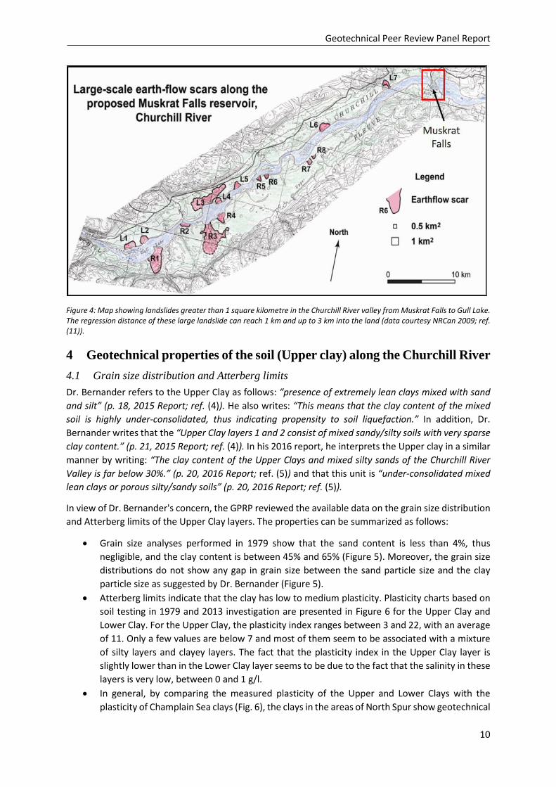
3 Landslide morphology Numerous evidences of slope instability can be found in the form of landslide scars along the Churchill River shoreline (Figs 3 and 4). There are also records of landslides along the Churchill River and at the North Spur (e.g. 1978 and 2010 landslides). A common feature of the landslides observed in the area is that they commonly show bowl-shaped scars and that little debris remain in the landslide crater. The retrogression distances can reach up to 3 km into the land. These features are strong indications that the landslides along the Churchill River are mostly of the flowslide type where the retrogressive process starts following an initial rotational failure.
The type of landslides registered in the Churchill River valley is comparable in size and morphology to the landslides mapped in sensitive clays in Eastern Canada (ref. (9)) and in Norway (ref. (10)). Thus in GPRP's opinion, it is correct and responsible to use tools and methods commonly used in geotechnical practice (state-of-practice) to evaluate the stability of the slopes at the North Spur. This includes the use of the Limit Equilibrium Method as discussed in Chapter 5.
GPRP's conclusion, Issue 1 - "Extraordinary landslide and geomorphological features" Based on the information provided by SLI, the GPRP considers that most of the landslides along the Churchill River valley and at the North Spur are either rotational slides or retrogressive flowslides, and that they are comparable to many of the landslides observed in sensitive clays elsewhere in Eastern Canada and Norway.
Québec
Site
NL and Labrador
Geotechnical Peer Review Panel Report
10
Figure 4: Map showing landslides greater than 1 square kilometre in the Churchill River valley from Muskrat Falls to Gull Lake. The regression distance of these large landslide can reach 1 km and up to 3 km into the land (data courtesy NRCan 2009; ref. (11)).
4 Geotechnical properties of the soil (Upper clay) along the Churchill River 4.1 Grain size distribution and Atterberg limits Dr. Bernander refers to the Upper Clay as follows: “presence of extremely lean clays mixed with sand and silt” (p. 18, 2015 Report; ref. (4)). He also writes: “This means that the clay content of the mixed soil is highly under-consolidated, thus indicating propensity to soil liquefaction.” In addition, Dr. Bernander writes that the “Upper Clay layers 1 and 2 consist of mixed sandy/silty soils with very sparse clay content.” (p. 21, 2015 Report; ref. (4)). In his 2016 report, he interprets the Upper clay in a similar manner by writing: “The clay content of the Upper Clays and mixed silty sands of the Churchill River Valley is far below 30%.” (p. 20, 2016 Report; ref. (5)) and that this unit is “under-consolidated mixed lean clays or porous silty/sandy soils” (p. 20, 2016 Report; ref. (5)).
In view of Dr. Bernander's concern, the GPRP reviewed the available data on the grain size distribution and Atterberg limits of the Upper Clay layers. The properties can be summarized as follows:
• Grain size analyses performed in 1979 show that the sand content is less than 4%, thus negligible, and the clay content is between 45% and 65% (Figure 5). Moreover, the grain size distributions do not show any gap in grain size between the sand particle size and the clay particle size as suggested by Dr. Bernander (Figure 5).
• Atterberg limits indicate that the clay has low to medium plasticity. Plasticity charts based on soil testing in 1979 and 2013 investigation are presented in Figure 6 for the Upper Clay and Lower Clay. For the Upper Clay, the plasticity index ranges between 3 and 22, with an average of 11. Only a few values are below 7 and most of them seem to be associated with a mixture of silty layers and clayey layers. The fact that the plasticity index in the Upper Clay layer is slightly lower than in the Lower Clay layer seems to be due to the fact that the salinity in these layers is very low, between 0 and 1 g/l.
• In general, by comparing the measured plasticity of the Upper and Lower Clays with the plasticity of Champlain Sea clays (Fig. 6), the clays in the areas of North Spur show geotechnical
Geotechnical Peer Review Panel Report
11
characteristics that are similar to those of other clays from Eastern Canada. The same is true for the clays in Norway (ref. (12)).
• The liquidity index of the upper clay varies between 0.6 and 2.8, with an average value of 1.3, meaning remoulded shear strength (sur) of approximately 0.8 kPa (ref. (13)). This clay is highly sensitive but would not be classified as “quick” clay, according to the Swedish Standards that set an upper limit on the remoulded shear strength to 0.4 kPa.
• In the context of earthquake, with a plasticity index higher than 7%, Boulanger & Idriss (2008) (ref. (14)) classify the upper clay as “clay-like soil” susceptible of cyclic softening, but not as “sand-like soil” that is susceptible of liquefaction (Report ref. (2)). This is confirmed by LeBoeuf et al. (2016, ref. (15)) who show that sensitive clays from Eastern Canada are prone to cyclic softening but not to liquefaction.
• The Lower Clay presents a grain size distribution similar to that of the Upper Clay. The salinity is higher than 5 g/l, leading to a plasticity index slightly higher (average 16) than in the leached Upper Clay layers (Figure 6), but still comparable to the Champlain Sea clays. The liquidity index is between 0.1 and 2, with an average of 0.6.
In the GPRP's opinion, the material description by Dr. S. Bernander is not a representative description of the Upper Clay at the North Spur. The Upper Clay at North Spur has only a few percent of sand, no gap in grain size between sand and clay, between 45 and 65% of clay particles and an average plasticity index of 11%.
Figure 5: Typical grain size distribution curves for the Upper Clays at the North Spur (courtesy Muskrat Fall Corporation).
Geotechnical Peer Review Panel Report
12
Figure 6: Plasticity chart for (left) the Upper Clay and (right) the Lower clay at the North Spur (data courtesy of the Muskrat Falls Corporation).
4.2 Hydraulic conductivity Dr. Bernander supports his soil description on the basis of the hydraulic conductivity measurements or inferences for the Upper Clay. Dr. Bernander interprets the hydraulic conductivity of the Upper clay to be a value of 10-7 m/s and finds that this value is high for a clayey soil. The GPRP agrees that a hydraulic conductivity of 10-7 m/s is high for a clayey soil.
The hydraulic conductivity of the stratified drift is discussed in the Design Report (Section 4.2.2; ref. (1)). The stratified drift is formed of different interbedded soils varying between silty clay to silty sand. The stratigraphy is complex. It is thus difficult to measure the hydraulic conductivity of sub-units. In addition, it is very difficult to measure hydraulic conductivity in situ (and in the laboratory), and it is generally not used as a soil classification parameter.
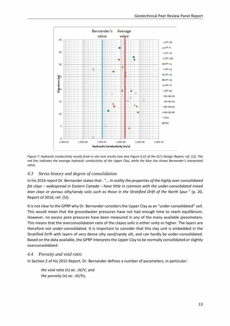
Hydraulic conductivity values for the North Spur were estimated from in situ permeability tests and deduced from CPTU dissipation tests. The results are reproduced in Figure 7. The measured/inferred values vary between 6 x 10⁻¹⁰ and 3 x 10⁻⁷ m/s, with an average of 6 x 10⁻⁹ m/s (red line on Figure 7) compared to Dr. Bernander's value of 10-7 m/s (blue line on Figure 7). Typical hydraulic conductivity values in different soils are presented in Table 2 below.
Table 2: Typical values of soil hydraulic conductivity (ref. (16)).
Soil type Hydraulic conductivity (m/s) Gravel 1 – 10-2 Coarse sand 10-2 – 10-5 Fine sand, silty sand, silt, mixture of silt and clay, stratified clays
10-5 – 10-9
Clay (homogenous) < 10-9
Considering only the clay units, a representative value would be smaller than 6 x 10⁻⁹ m/s , more typical of the hydraulic conductivity of natural clays, such as those found in Eastern Canada clays (ref. (38)).
In view of the data at the North Spur, the GPRP does not agree with Dr. Bernander's description of the Upper Clay layers on the basis of hydraulic conductivity.
Geotechnical Peer Review Panel Report
13
Figure 7: Hydraulic conductivity results from in situ test results (see also Figure 4.22 of the SLI's Design Report; ref. (1)). The red line indicates the average hydraulic conductivity of the Upper Clay, while the blue line shows Bernander's interpreted value.
4.3 Stress history and degree of consolidation In his 2016 report Dr. Bernander states that : “… in reality the properties of the highly over-consolidated fat clays – widespread in Eastern Canada – have little in common with the under-consolidated mixed lean clays or porous silty/sandy soils such as those in the Stratified Drift of the North Spur.” (p. 20, Report of 2016; ref. (5)).
It is not clear to the GPRP why Dr. Bernander considers the Upper Clay as an “under-consolidated” soil. This would mean that the groundwater pressures have not had enough time to reach equilibrium. However, no excess pore pressures have been measured in any of the many available piezometers. This means that the overconsolidation ratio of the clayey soils is either unity or higher. The layers are therefore not under-consolidated. It is important to consider that this clay unit is embedded in the Stratified Drift with layers of very dense silty sand/sandy silt, and can hardly be under-consolidated. Based on the data available, the GPRP interprets the Upper Clay to be normally consolidated or slightly overconsolidated.
4.4 Porosity and void ratio In Section 2 of his 2015 Report, Dr. Bernander defines a number of parameters, in particular:
the void ratio (n) as: ∆V/V, and the porosity (e) as: ∆V/Vs,
Geotechnical Peer Review Panel Report
14
where V is the total volume of soil, Vs is the volume of solid material and ∆V is the volume of the voids of the coarse granular material. Dr. Bernander does not explain how to determine ∆V, so that these parameters cannot be verified.
This is very confusing as, in the international literature, the void ratio is defined as “e” and the porosity as “n”. In addition, in the international literature, ∆V would be the total volume of voids, i.e. the volume not occupied by particles of clay and coarser material, and not the volume of the voids of the coarse granular material. The ncrit defined by Dr. Bernander is thus not the “critical void ratio” described by Terzaghi & Peck (1967) (ref. (17)). As far as the GPRP is aware, the concept of critical void ratio is applied only to granular soils and not to clayey soils.
In Section 2.3.2 of the same Report, Dr. Bernander mentions the volume occupied by clay, Vclay, but does not specify how to determine this quantity. In the same section and further in Section 2.4, Dr. Bernander describes the behaviour of a virtual soil that would be a “mixed granular soil with small clay content” that could liquefy, without mentioning what would be the maximum clay content at which liquefaction could occur. The behaviour will depend on the type of clay mineral. However, studies made by Chapuis (1990) (ref. (18)) on sand-bentonite mixtures and by Hight et al. (1994) (ref. (19)) on clayey sands from the Gullfaks site in the Norwegian North Sea indicate that the maximum clay content at which sand-like behaviour could occur could be around 15 to 25%. With a clay content of about 50% (see Fig. 5), the Upper Clay is very far from these conditions.
4.5 Unit weight In Section 3 of his 2016 Report, Dr. Bernander discusses the physical properties of the Upper and Lower Clays. Comparing the unit weights with typical values provided by Terzaghi & Peck (1967), ref. (20)) for sands, he concludes that being smaller, it proves that these materials are of a loose composition. However, the Upper and Lower Clays are not sands as they contain about 50% of clay particles. It is just normal that they have lower unit weight and higher void ratio than sands. This is evidenced in the table of Terzaghi & Peck (1967), ref. (20) used by Dr. Bernander.
From field observations made by SLI (personnel communications) and photographs, it appears that the Upper Clay has been removed for the construction of the cut-off wall over a length of about 1 km and a width of 0.6 m with a clam-shell to large depths. During removal and hauling of the clay, there was no evidence of significant remoulding or liquefaction of the clay (i.e. the clay could easily be loaded on a truck). This is a good indication that the Upper Clay is neither a metastable nor a "quick" material as described by Dr. Bernander.
Dr. Bernander also states (p. 12, 2015 Report; ref. (4)) that for liquefiable soils such as those he describes, “the results of soil investigations of the standard type are extremely unreliable.” As mentioned above, the Upper Clay unit consists of clay material such as those found elsewhere in Eastern Canada and Norway. The GPRP therefore believes that the soil investigations performed on the North Spur are reliable, at least as reliable as other geotechnical investigations for other construction projects.
GPRP's conclusion, Issue 2 - "Extreme sensitivity and particular structure" of North Spur soil The clayey soils found at the North Spur are comparable to those found in Eastern Canada and in Norway. In fact, clayey soils with clay content of about 50% are very common in Champlain Sea clays (St-Lawrence lowlands). Some deposits of Champlain Sea clays and most of those from the Laflamme Sea (Saguenay area) and Goldthwait Sea (North coast of the St-Lawrence Gulf) have clay contents less than 30%; they may have plasticity index smaller than 7% and liquidity index larger than 2 (see Leroueil
Geotechnical Peer Review Panel Report
15
et al., 1983 (ref. (13)), for a synthesis of these characteristics). Such soil deposits are also very common in Norway (e.g. ref. (21) (22)) .
5 Application of the Limit Equilibrium Method (LEM) for slope stability analysis at the North Spur
5.1 General The Limit Equilibrium Method (LEM) is a widely used and commonly accepted approach in geotechnical engineering practice in Scandinavia and Eastern Canada, and elsewhere in the world. The approach can be used to evaluate the stability of sensitive clay slopes. The method is semi-empirical and uses the geometry of the considered slope, the hydrogeological conditions and the mechanical soil properties. When correctly applied, the method gives a good estimation of the stability of a slope for a first time failure (i.e. initial failure).
A landslide is an undesirable event, but also an unintended full-scale test, and the profession can learn from them by back-calculating the failure to calibrate the LEM procedures and determine the appropriate soil strength parameters to be used. Dr. Bernander wrote: “None of the extensive landslides known to this Reviewer were predicted – or could even be explained in hindsight – by using stability analysis based on the conventional elasto-plastic LEM mode”. However studies of recent and past landslides have shown that the LEM can be adequate for the evaluation of slope stability in the context of first time failures that have led to large retrogressive flow slides in sensitive clays in Eastern Canada (e.g. refs. (23); (24)) and in Norway (e.g. refs. (25), (26)).
The LEM allows the calculation of the potential of initial failure which can lead to a large catastrophic failure in sensitive material (i.e. flowslide, spread and other retrogressive landslide). However, LEM cannot be applied to explain the entire event occurring in these large landslides, as it would then give a factor of safety larger than one. This was shown for the 2010 Saint-Jude spread, where the drained local factor of safety using the LEM applied to the initial slope was 0.99 and the undrained factor of safety for the entire landslide that took place was above 2 (ref. (24)).
The failure mechanism of large landslides has been studied in various research projects; refs. ( (27) (28)), but no method has yet been accepted in engineering practice to take into account the complete event. The current accepted engineering practice is to rely on properly applied and calibrated LEM to estimate the stability of a slope for a local first time failure. If the failure of the first soil block can be prevented, a retrogressive landslide will not occur.
Recent research in Norway (refs. (29) and (30)) recommends the use of the LEM approach in practice for the analysis of slope stability in sensitive and quick clays, with the addition of a correction factor, called Fsoftening, to account for the reduction of the clay shear strength after the peak shear strength has been reached, and to partially account for strain compatibility on the failure surface.
5.2 Limit equilibrium method applied to the North Spur SLI has noted that the North Spur has been subjected to several landslides on both of its downstream and upstream sides (ref. (1)). The standing slopes on both sides were therefore considered to have a safety factor of at least 1.0. Any slope improvement work thereafter represents an actual gain in safety of the slopes (even if there are some uncertainties in the material parameters). The LEM method was used to evaluate the effect of such remediation measures. The LEM method was also tested and calibrated with the back-calculation of the 1978 landslide that occurred on the downstream side of the Spur (ref. (8) and Fig. 3) and on the Edward Islands landslide that occurred in 2010 (AMEC 2011; (31)).
Geotechnical Peer Review Panel Report
16
In the analysis of the North Spur, one section considered as the most critical was selected by SLI to represent the worst case conditions on both sides of the Spur (ref. (1)). The hydrological conditions were based on SLI's observations of the piezometers put in place on the North Spur. Calculation from LEM applied to both critical sections in their initial conditions, before mitigation and remediation, gave safety factors close to 1.0. As the stability of these slopes was precarious, these safety factors enabled SLI to calibrate the LEM and to confirm the physical and mechanical parameters used are appropriate for the soil at the North Spur.
According to SLI, calculations were performed for various conditions on both sides of the North Spur throughout the project (during construction, end of construction and at various period of reservoir impoundment) and compared to the required safety factors for each of these loading conditions in accordance with design criteria. As an example of the effect of the mitigation measures for a slope on the Eastern side of the North Spur, the critical factor of safety was increased from 1.0 to 1.6. This is a 60% increase in the stability of the slopes, and within the reduction associated with Fsoftening, if one should use the results of some of the most recent researches (ref. (30)).
GPRP's conclusion, Issue 3 - Application of the Limit Equilibrium Method to the North Spur The methodology applied using the LEM by SLI to evaluate the stability of the North Spur for an initial landslide corresponds to the current state of practice. SLI works concentrated in using the LEM to prevent a first-time failure that could initiate a large retrogressive landslide.
6 Progressive failure One of Dr. Bernander’s main criticisms is that progressive failure has not been adequately taken into account by SLI. Progressive failure observed in sensitive clay is a function of their strain-softening behaviour and can be initiated either near the toe of the slope and progress inside the intact deposit or be triggered upslope and progress downward (refs. (32), (33), and (34)). In all cases, there must be a triggering factor bringing the soil to exceed its peak shear strength somewhere.
SLI have recognised the landslide activity along the Churchill River valley and on both sides of the North Spur itself (refs. (1) and (3)). SLI also acknowledged that progressive failure could occur in the soil in this area. They noted that for the North Spur slopes, the potential factors that could initiate progressive failure are: (a) failure at the toe of the slopes resulting from human activities, erosion, pore water pressure increase or seepage; (b) upslope loading such as placement of fill material in the upslope areas and pressure on the cut-off wall, and (c) earthquake loading.
SLI’s strategy has been to prevent the initiation of a failure, both downwards and upwards, by not allowing the peak shear strength of the soil to be exceeded in the North Spur, thus restricting the need for further analysis of progressive failure. With this strategy, SLI designed correction measures to improve the stability on both sides of the North Spur (see also Chapter 8).
SLI verified the efficiency of the mitigation/remediation to prevent upward progressive failure by calculating the safety factors using the LEM approach, as described above. The mitigation measures are illustrated in Figure 10 . These measures were prioritized to prevent the peak shear strength to be exceeded near the toe of the slope, which could trigger failure near the toe of the slope.
Likewise, to prevent the initiation of downward progressive failure from upslope, the following restrictions have been put in place by the Muskrat Falls Corporation and SLI (ref. (35)):
a) No surcharge on the North Spur without approval by the Engineer; b) No pile driving;
Geotechnical Peer Review Panel Report
17
c) No blasting; d) No excavation without approval by the Engineer; e) Obligation of contractor working methods to be reviewed by the Engineer; f) Consideration of the North Spur as a dam (no access to the public) after stabilization works;
These restrictions will prevent excessive loading such that plastic shear strains, which could trigger large-scale progressive failure, will not be generated in the sensitive clays. SLI confirmed that the above restrictions are part of the maintenance strategy of the North Spur (ref. (35)).
SLI also conducted finite element (FE) analyses to assess the potential for both downward and upward progressive failures (ref. (3)). The methodology followed consisted in determining the maximum shear stress on potential horizontal failure surfaces for the most critical cross section, defining this maximum shear stress as reference shear strength at the considered elevation for the North Spur, and comparing shear stresses on similar potential failure surfaces with the reference shear strength. By keeping the shear stresses well below the reference shear strength, they were sure that progressive failure cannot be initiated.
The soil was modelled as an elastic-perfectly plastic material and the calculations were performed for before and after the stabilization measures (discussed in Section 8) and also with full reservoir. As worst case scenario, SLI considered Section A (located on Fig. 3) where the safety factor of the slope was obviously close to 1.0. After stabilization works, the safety factor was expected to increase to 1.6. The calculated shear stresses on horizontal planes at elevation +20 m (Upper Clay) and -10 m (Lower Clay) are shown in Figure 8. It can be seen that before stabilization (red lines), the maximum shear stresses are respectively 162 kPa and 188 kPa on both surfaces. SLI considered these values as reference shear strengths for other analyses. Figure 8 also shows reductions of 45% at elevation +20 m and 25% at elevation -10 m of the maximum shear stresses after the stabilization works (black lines).
Section B (located on Fig. 3) was selected as representative of the narrow part of the Spur. Results from the numerical analysis are presented in Figure 9. The horizontal shear stress on the horizontal planes at elevations +20 m and -10 m are presented for the conditions before stabilization (red lines), after stabilization (black lines) and after reservoir impoundment (dashed blue lines). It can be seen that the model predicts no significant change in shear stress due to stabilization works on the upstream side of the North Spur, but a significant one on the downstream side (25% at elevation -10 m). On the other hand, reservoir impoundment produces a reduction of about 25% of the horizontal shear stresses on the upstream side of the North Spur, and has no effect in the center and downstream side of the North Spur. The reference shear strengths established in Section A are also shown, in red, in Figure 9. It can be seen that the mobilized shear stresses on both surfaces are less than 50% of the reference strengths. Based on these analyses, SLI concluded that a progressive failure will not be initiated after stabilization and impoundment, and therefore did not need to model large deformation progressive failures. Consequently, the use of the large deformation shear strength of clay is irrelevant to SLI’s modelling approach.
The analyses performed by SLI considered horizontal potential failure surfaces and compared maximum shear stresses in Sections such as B with those in the most critical Section A. Similar analyses could have also been performed for slightly inclined surfaces, but the results would have been similar.
GPRP's conclusion, Issue 4 - Progressive failure analysis of the North Spur In view of the analyses performed by SLI, the GPRP finds that the approach used is conceptually acceptable to take into account the initiation of progressive failure. It is however important that Nalcor
Geotechnical Peer Review Panel Report
18
Energy have procedures and routines to ensure that the restrictions listed a) to f) are observed at all times, also by persons outside of SLI /Nalcor Energy.
Figure 8. Section A (located on Fig. 3) through the North Spur and shear stresses applied on horizontal surfaces in the Upper and Lower Clays(s) before (BS) and after stabilization (AS) (from Leahy et al., 2017).
Geotechnical Peer Review Panel Report
19
Figure 9. Section B (located on Fig. 3) through the North Spur and shear stresses applied on horizontal surfaces in the Upper and Lower Clays(s) before (BS) and after stabilization (AS) (from Leahy et al., 2017).
7 Dynamic analysis and effect of seismic activity In his 2016 report, Dr. Bernander questions the soundness and integrity of the seismic analyses performed by SLI (Chapter 5.3 in ref. (5)). Unfortunately Bernander only refers to SLI's Design Report and not to the Dynamic Analysis Report where all of the seismic and dynamic analyses performed are documented (ref. (2)). In the latter, a state-of-the-art 2D non-linear dynamic response analysis was performed for the most critical slope, after its stabilization, for an earthquake with a return period of 10 000 years. The Cyclic Resistance Ratio (CRR) was estimated based on CPT and SPT for the granular materials, and for cyclic softening for the clay layers (Idriss & Boulanger, 2008; ref. (14)). The results are presented in the Report on Dynamic Analysis Study; ref. (2)). They indicate no potential for liquefaction of the sand layers, no potential for cyclic softening for the clay layers, and displacements of the crest of less than 3 cm both horizontally and vertically. The report concludes that the North Spur's integrity is thus not expected to be affected by an earthquake with a return period of 10 000 years.
GPRP's conclusion, Issue 5 - Dynamic analysis and liquefaction potential The GPRP considers that SLI used State-of-the-Art methodology to assess the resistance of the North Spur to earthquakes. SLI’s results show that the displacements of the crest would be extremely small and that the integrity of the slope would be assured.
8 Mitigation measures/ remedial measures Historical records of landslides and results from stability analyses show that the stability of natural slopes along the North Spur is low (i.e. a factor of safety close to 1.0). Already in the late 70's, SLI recognized the importance of mitigation measures and stabilization works to ensure safe hydropower development around the North Spur (ref. (36)). The objectives of the latest stabilization plan proposed by SLI are meant to (ref. (1)):
• Lower the piezometric level • Inhibit infiltration from the reservoir and control the groundwater in the North Spur • Capture and evacuate seepage water • Improve the stability of the slopes • Protect the slopes against erosion
Some of the mitigation/remediation measures necessary to insure the short- and long-term safety of the area are shown in Figure 10. The measures include cut-off walls and till blanket, slope regrading, downstream finger drains, stabilization of the kettle lakes area, erosion protection along the river with rockfill embankments and relief wells.
The stabilization works proposed and designed by SLI were reviewed in 2013 by i) an Independent Engineer (ref. (37)) and ii) Hatch Ltd. (Cold Eye review of Design and Technical Specification, North Spur Stabilization Works) ref. (38).
In his reports, Dr. Bernander (refs. (4) and (5)) comments on a few aspects related to the remediation measures and especially the cut-off walls, the finger drains and the erosion protection measures. Each of these items is discussed below.
Figure 10. Overview of stabilization works at the North Spur (picture courtesy of Muskrat Falls Project).
Geotechnical Peer Review Panel Report
21
8.1 Cut-off walls (COW) and till blanket The main objective of the cut-off walls (COW) and till blanket, located on Figure 10, is to control/minimize the seepage of water coming from the West and North-West sides of the North Spur, and prevent unfavourable effects on the stability of the downstream slope. The cut-off walls and till blanket will also reduce the potential for erosion and piping in the stratified drift (sand and silt layers). Moreover, it will provide a better control on water pressure coming from the upstream side.
To understand the effects of reservoir impoundment and other mitigation measures on the North Spur, SLI conducted FE analysis using the software SIGMA/W (ref. (3)). The lower diagrams of Figure 9 show the horizontal shear stress on two planes at EL+20 m and EL-10 m for the conditions before stabilization, after stabilization and after reservoir impoundment. These analyses were performed for an idealized condition (e.g. elastic soil behaviour). SLI's main interest was to visualize the changes in shear stress for the three different stages. Horizontal planes were therefore selected by SLI, considering that these changes of shear stresses would be similar on slightly inclined planes.
To understand results presented by SLI, it is important to take into account the geological history of the North Spur. Following the emergence of these soils out of the sea several thousands of years ago, and before the erosion of the Churchill River fully started, the shear stress along the horizontal planes was zero (level ground). After erosion and formation of the river, shear stresses increase (westward on the upstream side and eastward on the downstream side), which are shown by the red lines in Figure 9.
The stabilization works on the North Spur slightly changed the shear stress and the results are shown by the solid black lines on the same figure. Reservoir impounding, as shown by the blue dashed lines, adds some load on the West side of the Spur, partly recovering loads which existed before the formation of the valley and thus decreases the shear stresses. SLI’s analyses show that impoundment pressure on the upstream slope in fact decreases westward horizontal shear stresses on the upstream side, while it remains unchanged, approximately from the middle of the Spur to the downstream side, as compared to the horizontal stress without impoundment (compare blue dashed line with solid black line in the lower diagrams of Figure 9).
The COW on the upstream side of the Spur is located near the toe of the slope and is superimposed by a till blanket acting as an erosion barrier and counter fill (Figure 11). However, in his analysis, Dury assumed an impermeable COW located well within the crest of the slope and without the presence of the till blanket (Figure 12). Moreover, the elevation and height of the COW in Bernander's analyses is very different than the actual COW location. In reality, the top of the COW is slightly above +22 m while Bernander's assumes an elevation of the COW at around + 50m. SLI reported, based on recent surveys, piezometric water head slightly below +39 m (similar to full reservoir level) in the piezometers located behind the COW and till blanket. This water pressure is likely coming from water infiltration from the ground surface in the North Spur.
In their analyses, Dury and Bernander assumed “a gigantic external force (locally on the COW)”, assuming the water pressure resulting from impoundment on only one side of the COW (blue triangle on Figures 12 and 13), in addition to using incorrect geometry and incorrect location for the COW. Actually, the many piezometers installed in the North Spur show that the water pressure in the Spur will be acting on both sides of the COW (red triangle on Figure 13). If the calculation is performed for a COW at the actual location, the force on the wall will be much less than the force calculated by Dr. Bernander.
Geotechnical Peer Review Panel Report
22
GPRP's conclusion, Issue 6 - Mitigation and remedial measures: Cut-off walls and till blanket
The GPRP finds that the COW analysed by Dury and Dr. Bernander is not representative of the actual COW and till blanket on the North Spur. The GPRP does not expect that the cut-off walls will "create a gigantic force", as calculated by Dury and Bernander, which could trigger a downward progressive failure. Actually, the existing piezometer data show that water pressure within the Spur is already at a level similar to the level of the reservoir after impoundment.
Figure 11: Cross-section A-A' of the slope with the cut-off wall on the upstream side of the Spur (Courtesy Muskrat Falls Corporation).
Geotechnical Peer Review Panel Report
23
Figure 12: Cross-section A-A' in the Dury (2017) assessment of the cut-off wall and impoundment of the water reservoir. Note the difference in the COW in the actual cross section (Fig. 11) and the Dury model (Fig. 12).
Figure 13: Details of cross-section A-A' in the Dury (2017) assessment of the cut-off wall (red triangle is added). The piezometer data from the Spur show existing water pressure also on the downstream side of the cut-off wall (red triangle).
Geotechnical Peer Review Panel Report
24
8.2 Finger drains SLI designed and recommended the installation of finger drains on the downstream side of the Spur to improve drainage of the slopes and hence the stability of the slopes. In his reports (ref. (4) (5)) Dr. Bernander acknowledges that the finger drains will enhance and maintain the drainage of the slopes on the downstream face of the Spur. However, he stipulates that the drains will have no effective guarantee against progressive failure development.
GPRP's conclusion, Issue 6 - Mitigation and remedial measures: Finger drains The GPRP agrees that the finger drains are necessary to maintain appropriate drainage on the slopes on the downstream face of the North Spur and to reduce infiltrations. However, the drains will also, to some extent, increase the local stability of the slopes and thereby reduce the susceptibility of an initial failure occurring on this side of the North Spur (which is the main function of these drains).
Figure 14: Overview of finger drains on the downstream side of the Spur (picture courtesy of Muskrat Falls Project).
8.3 Erosion protection measures along the river SLI recognized early in the Muskrat Falls project that the upstream and downstream slopes needed to be protected from erosion by waves and ice to ensure long-term slope stability. To this aim, SLI designed protection measures using a rip rap protection layer both on the upstream and downstream slopes of the Spur (ref. (1)).
Dr. Bernander mentions in his report (chapter 5; ref. (4)) that the erosion protection is a useful measure for slope stabilization, but that is has little effect in the risk related to progressive landslide development.
GPRP's conclusion, Issue 6 - Mitigation and remedial measures: erosion protection measures The GPRP agrees with SLI that erosion protection measures are necessary along the river to ensure that both wave and ice erosion be avoided in the future. The erosion protection is essential to avoid initial failures on both sides of the Spur in the future.
8.4 Other mitigation measures and testing proposed by Dr. Bernander In his 2016 report (chapter 5.8, ref. (5)), Dr. Bernander writes "A metastable structure in a natural sand deposit is very difficult to detect, because the structure collapses during sampling and subsequent transportation". To verify this, Dr. Bernander proposes a testing method consisting of driving closely spaced piles in the soil deposit to a depth larger than 50 m and thereafter measuring settlements at
Geotechnical Peer Review Panel Report
25
the North Spur. This leads to a suggestion for mitigation which is “the compaction of the under-consolidated silty clay soils of the North Spur to the point that they are no longer vulnerable to liquefaction under dynamic loading actions.”
This recommendation is extremely surprising from someone who repeatedly says that the Upper Clay has a "high propensity for liquefaction". Indeed, the strength of such a saturated fine-grained soil could be reduced to its remoulded value through such process.
Results from CPTU and SPT tests show that the silty sand and sandy silt within the stratified drift are very dense (N>50) and are not susceptible to liquefaction (see also Chapters 4 and 7 above). For the Upper clay, such testing, as proposed by Dr. Bernander, could have a very negative impact on the soil, remoulding the clay and generating excess pore pressures that would decrease the stability of the North Spur and take a long time to dissipate.
GPRP's conclusion, Issue 6 - Mitigation and remedial measures: closely-spaced driven piles The GPRP is strongly against the testing approach proposed by Dr. Bernander because the excess pore pressure generated by such method would undermine the stability of the slopes in the sensitive clay and hence of the entire North Spur.
9 Consequences of landslide and flood wave The banks of the Churchill River are composed of sedimentary deposits that, under certain meteorological and hydrogeological conditions, are susceptible to landslides. The most recent documented event occurred at Edwards Island during the winter of 2010 on the right bank of the river near km 72. There was physical evidence following the Edwards Island landslide suggesting that a 4.5 m high wave was generated from the material flowing into the river (ref. (39)). Also of particular interest to the project is the November 1978 landslide that occurred on the downstream side of the North Spur, producing approximately 1,000,000 m3 of flowslide debris in the river and on its shoreline. Historical and more recent bank instabilities located within the future Muskrat Falls reservoir raise concern regarding the impact of reservoir impoundment and rising water levels on the stability of the river banks. Particularly, the adverse effects associated with a landslide generated wave are of concern, on the permanent structures or on the safety of site personnel during construction.
The issue of reservoir landslide-generated impulse waves and their direct impacts on the Muskrat Falls facility has been analysed by SLI over the last years. Conclusions of the work are presented in a SLI report (ref. (40)). The state-of-the-art simulations results are taken directly into the design of the dam to minimize the risk of overtopping from potential landslide-generated tsunami waves. The concept, analysis procedure and results obtained by SLI were also presented and discussed in a workshop held in Vancouver on October 16th 2013 between Nalcor, SLI, BC Hydro and BGC.
One of the most important aspects to consider with regards to dam breaching is the consequence on the downstream environment and population. In Bernander's opinion this aspect has not been investigated sufficiently by SLI (ref. (5)). Actually, this important aspect was investigated in 2015 by Hatch (ref. (41)), where they simulated the downstream consequences of a hypothetical breach of the North Dam at Muskrat Falls and also of the North Spur. The characteristics for a hypothetical breach of the North Spur were calculated using empirical predictive equations based on historical data. Sensitivity analysis of North Spur breach parameters was also carried out.
According to SLI, for the North Spur base case breach scenario, results show peak water levels lower than those of the North Dam breach scenario. The analyses conducted by Hatch provide detailed information on the potential peak water level resulting from hypothetical breach and the time to peak
Geotechnical Peer Review Panel Report
26
water level arrival at Happy Valley-Goose Bay based on different weather and flood scenarios. According to SLI these results have been implemented in the emergency plans and early warning systems that are now in place in Happy Valley – Goose Bay in case of any dam breach (refs. (42) (35)).
GPRP's conclusion, Issue 7 - Consequences of landslide and flood to downstream populated area It is GPRP's opinion that the aspects of dam breach and consequences downstream have been investigated and attended to.
10 Conclusions The Geotechnical Peer Review Panel (GPRP) has examined the concerns expressed by Dr. S. Bernander and Dr. L. Elfgren in a series of reports and in the MSc. thesis of student R. Dury. A review of the available engineering documentation on the North Spur was also completed. The GPRP noted seven issues raised and questioned by Dr. Bernander. The main conclusions of the GPRP with respect to Dr. Bernander's objections are as follow:
Issue 1 - "Extraordinary landslide and geomorphological features" along the Churchill River Valley The GPRP concludes that most of the landslides along the Churchill River valley and at the North Spur are either simple rotational slides or retrogressive flowslides. These features are comparable in size and morphology to landslides observed in sensitive clays elsewhere in Eastern Canada and Norway. Hence the GPRP considers that it is appropriate to use state-of-the-art tools and methods for the evaluation of slope stability at the North Spur, including the limit equilibrium method.
Issue 2 - "Extreme sensitivity and particular structure" of the North Spur soil properties compared to the Eastern Canadian and Scandinavian clays The GPRP does not agree with Dr. Bernander's postulate that the Upper clay is under-consolidated. In fact, no excess pore-pressure has been registered in the Upper clay, and this clay is embedded within very dense silty sandy soils.
The aspects of critical void ratio discussed by Dr. Bernander are also confusing as this is normally applicable to granular materials and not to clays.
Dr. Bernander describes the Upper clay as a metastable material and as a mixed sandy-silty soils with very sparse clay. From the literature this happens only when the clay content is less than 15 to 25%. In fact, the Upper clay has a clay content between 45 and 65 %.
The GPRP concludes that the clayey soils found at the North Spur are comparable to those found in Eastern Canada and in Norway. The material described by Dr. Bernander is not representative of the Upper Clay within the stratified drift unit.
Issue 3 - Application of the Limit Equilibrium Method (LEM) to the North Spur Dr. Bernander criticizes SLI for using LEM in stability analysis and mentions that extensive landslides cannot be predicted or explained by using LEM. The GPRP agrees in that the LEM cannot be applied to explain the entire event occurring in large retrogressive landslides. However, the LEM allows detecting initial failure which may lead to large catastrophic landslides in sensitive material. SLI's work has focused in using the LEM to prevent an initial failure and ensuing large landslide.
The GPRP concludes that the LEM methodology applied to evaluate the stability of the North Spur (initial landslide) corresponds to the current state-of-practice.
Geotechnical Peer Review Panel Report
27
Issue 4 - Progressive failure analysis of the North Spur One of Dr. Bernander main criticism is that progressive failure has not been taken into account by SLI. SLI has investigated the shear stress distribution in the North Spur before and after stabilization measures and after impoundment. SLI’s strategy is to prevent the initiation of failure downslope or upslope by limiting the shear stress to a value well below the peak shear strength in the North Spur.
The GPRP concludes that the analyses performed by SLI are conceptually acceptable to take into account the initiation of progressive failure. It is however important that SLI have procedures and routines to ensure that the restrictions listed a) to f) are observed at all times, including by persons outside of SLI /Nalcor Energy.
Issue 5 - Dynamic analysis and liquefaction potential The GPRP concludes that a State-of-the-Art approach was applied to the North Spur to assess its resistance to earthquakes. SLI’s results indicate that the displacements of the crest would be extremely small under a 10 000-year earthquake and that the integrity of the North Spur is assured.
Issue 6 - Mitigation and remedial measures at the North Spur The GPRP responds as follows to the comments from Dr. Bernander on the planned mitigation measures at the North Spur:
− The GPRP finds that the analyses of the COW presented Dury and Dr. Bernander are based on several incorrect assumptions. The results are therefore not realistic. The incorrect assumptions include the geometry of the problem and of the COW, and the initial pore pressure on the downstream side of the COW.
− Regarding the finger drains, the GPRP’s opinion is that they are necessary to maintain appropriate drainage on the slopes on the downstream face of the Spur and to reduce infiltrations and, to some extent, increase the stability of the slope.
− The GPRP concludes that erosion protection measures (rip rap) put in place by SLI are necessary along the river to prevent both wave and ice erosion in the future. This will reduce the susceptibility of an initial failure that could occur on both sides of the North Spur.
− The GPRP is strongly against Dr. Bernander's proposal of driving closely spaced piles in the North Spur to investigate if metastable soils are present. Such an investigation would generate excess pore pressure in the sensitive clay and undermine the stability of the slopes and hence of the entire Spur.
Issue 7 - Consequences of landslide and flood to downstream populated area The GPRP concludes that the aspects of dam breach and consequences downstream at Muskrat Falls have been investigated and attended to by SLI and covered by reviews performed by HATCH.
Geotechnical Peer Review Panel Report
28
11 References 1. SNC Lavalin. 2016. Lower Churchill Project - Engineering report, North Spur Stabilization Works - Design Report.
3. SNC Lavalin. 2015. North Spur Stabilization Works - Progressive Failure Study. 2015.
4. Bernander, S. 2015. Lower Chrurchill River - Riverbank stability report. Luleå Technical University, 2015.
5. Bernander, S. 2016. Safety and Reliability of the Muskrat Falls Dam, in Light of the Engineering Report of 21 December 2015 by Nalcor/SNC-Lavalin. s.l. : Luleå Technical University, 2016.
6. Dury, R. 2017. Progressive Landslides Analysis - Applications of a Finite Difference Method by Dr. Stig Bernander, Case Study of the North Spur at Muskrat Falls, Labrador, Canada. Luleå University of Technology, Department of Civil, Environmental and Natural Resources Engineering.
7. Jacques Withford Environmental Limited. 2000. Sea level history and Geomorphology of the Churchill River and Strait of Belle Isle. LHP 98-23 - Project no. 1213.
8. Leahy, D., Bouchard, R., Leroueil, S. 2017. Potential Landsliding at the North Spur, Churchill River Valley. In Landslides in Sensitive Clays, Springer International Publishing, pp. 213-223. .
9. Demers, D., Robitaille, D., Locat, P., & Potvin, J. 2014.Inventory of large landslides in sensitive clay in the province of Québec, Canada: preliminary analysis. In Landslides in Sensitive Clays. In Landslides in Sensitive Clays. Springer Netherlands. pp. 77-89
10. L’Heureux, J.S. 2012. A study of the retrogressive behaviour and mobility of Norwegian quick clay landslides. Landslide and engineered slopes: protecting society through improved understanding. . London: Taylor & Francis Group, pp. 981-988.
11. Natural Ressources Canada. 2009. Lower Churchill Hydroelectric Generation Project - Natural Ressources Canada Response to additional information provided by Nalcor Energy. NRCAN. http://www.ceaa.gc.ca/050/documents/40314/40314E.pdf.
12. Karlsrud, K., Hernandez-Martinez, F. 2013. Strength and deformation properties of Norwegian clays from laboratory tests on high-quality block samples. (12), 1273-1293, Canadian Geotechnical Journal, 2013, Vol. 50.
13. Leroueil, S. Tavenas, F. & Le Bihan, J.P. 4, 1983. Propriétés caractéristiques des argiles de l'Est du Canada. Canadian Geotechnical Journal, Vol. 20, pp. 681-705.
14. Idriss, I. M., Boulanger, R. 2008. Soil liquefaction during earthquakes. Earthquake Engineering Research Institute.
15. LeBoeuf, D., Duguay-Blanchette, J., Lemelin, J.-C., Péloquin, É. & Burckhardt. 2016. Cyclic softening and failure in sensitive clays and silts. G. Proc. 1st Int. Conf. on Natural Hazards & Infrastructure, Chania, Greece.
16. Holtz, R.D., Kovacs. W.D. 1981. An introduction to geotechnical engineering. Prentice-Hall Inc., 1981.
17. Terzaghi K., R.B. Peck. 1967. Soil mechanics in engineering practice.
18. Chapuis, Robert P. 1990. Sand–bentonite liners: predicting permeability from laboratory tests. Canadian Geotechnical Journal, Vol. 27, pp. 47-57.
19. Hight, D.W, Georgiannou, V.N. & Ford, C.J. 1994. Characterisation of clayey sands. Proc. 7th Int. Conf. on Behaviour of Offshore Structures, Boston, Vol. 1: 321-340., 1994.
20. Terzaghi, K. and R.B. Peck. Soil Mechaniscs in Engineering Practice, 2e Edition. New York: John Wiley & Sons, Inc., 1967. p. 729.
21. Gylland, A., Long, M., Emdal, A. and Sandven, R. 2013. Characterisation and engineering properties of Tiller clay. Engineering Geology, Vol. 164, pp. 86-100.
22. Lunne, T., M. Long, and C. F. Forsberg. 2003. Characterisation and engineering properties of Onsøy clay. Characterisation and engineering properties of natural soils 1: 395-427.
23. Lefebrvre, G. 1981. Fourth Canadian Geotechnical Colloquium: strength and slope stability in Canadian soft clay deposits. Canadian Geotechnical Journal, Vol. 18, pp. 420–442.
24. Locat, A., Locat, P., Demers, D., Leroueil, S., Robitaille, D. and Lefebvre, G. 2017. The Saint-Jude landslide of 10 May 2010, Québec, Canada: Investigation and characterization of the landslide and its failure mechanism. . Canadian Geotechnical Journal. , Vol. 54(10).
25. L’Heureux, JS, Nordal, S. and Austefjord, S. 2017. Revisiting the 1959 Quick Clay Landslide at Sokkelvik, Norway. Landslides in Sensitive Clays - From Research to Implementation. Springer. pp. 395-405.
26. Nordal, S., Emdal, A., L’Heureux, J.-S. & Strand, S.A. 2017. Stability of shoreline slopes – what did we learn from appointing committees to evaluate the cause of sliding? Fjellsprengningsteknikk - bergmekanikk - geoteknikk. Oslo. Paper no. 36. 21p.
27. Locat, A., Jostad, H.P. & Leroueil, S. 2013. Numerical modelling of progressive failure and its implications for spreads in sensitive clays. Canadian Geotechnical Journal, 2013, Vols. 50:961–978.
28. Dey, R., Hawlader, B., Phillips, R. & Soga, K. 2016. Numerical modeling of combined effects of upward and downward propagation of shear bands on stability of slopes with sensitive clay. 2076-2099, Int. Jour. for Numerical and Analytical Methods in Geomechanics, Vol. 40.
29. Norwegian Water Resources and Energy Directorate (NVE). 2016. NIFS final report 2012 - 2016. 2016. Rapport nr 92-2016.
30. Fornes, Petter and Jostad, Hans Petter. 2017. Correction factors for undrained LE analyses in sensitive clays. In: Landslides in Sensitive Clays. Springer International Publishing.
32. Bernander, S. 2011. Progressive Landslides in Long Natural Slopes. Formation, Potential, Extension and Configuration of Finished Slides in Strain-Softening Soils. Doctoral Thesis. ISBN: 978-01-7439-283-8. ISSN: 1402-1544: Luleå Tekniska Universitet.
33. Bernander, S. 2008. Downhill Progressive Landslides in Soft Clays. Triggering disturbance agents, Slide Propagation over horizontal or gently sloping ground, Sensitivity related to geometry. 2008:11│ISSN:1402: Luleå Tekniska Universitet.
Geotechnical Peer Review Panel Report
30
34. Locat, A., Leroueil, S., Bernander, S., Demers, D., Jostad, H.P. and Ouehb, L. 2011. Progressive failures in eastern Canadian and Scandinavian sensitive clays. 11, 2011, Canadian Geotechnical Journal, Vol. 48, pp. 1696-1712.
36. SNC-Lavalin Newfoundland Ltd. 1980. Muskrat Falls Power Development and 345 kV Transmission Intertie to Churchill Falls, Vol. II: Appendices. SNC-Lavalin Newfoundland Ltd.
38. Hatch Ltd. 2013. Cold Eye Review of Design and Technical Specifications North Spur. Stabilization Works, January 2014. MFA-HE-CD-2800-GT-RP-0001-01.
39. AMEC. 2011. Geotechnical Investigations - Edwards Island Landslide Churchill River, Labrador.
44. SNC Lavalin, 2013. Lower Churchill Project. Protection with Considerations for Ice Effects, Doc. No. MFA-SN-CD-0000-CVCVRP.
45. Tavenas, F., Jean, P., Leblond, P. & leroueil, S. 1983. The permeability of natural soft clays. Part II: Permeability characteristics. Canadian Geotechnical Journal, Vol. 20, pp. 645-660.
47. Bernander, S. 2000. Progressive Landslides in Long Natural Slopes. Licentiate Thesis. Lulea Univ. of Technology. *ISSN:1402–1757 * ISRN: LTU–LIC–00/16–SE.
Kontroll- og referanseside/ Review and reference page
Dokumentinformasjon/Document information Dokumenttittel/Document title Geotechnical Peer Review of Dr. S. Bernander's Reports and Analysis of the North Spur
Dokumentnr./Document no. 20170675-01-R
Dokumenttype/Type of document Rapport / Report
Oppdragsgiver/Client Muskrat Falls Corporation
Dato/Date 2018-02-02
Rettigheter til dokumentet iht kontrakt/ Proprietary rights to the document according to contract Oppdragsgiver / Client
Rev.nr.&dato/Rev.no.&date 0 /
Distribusjon/Distribution BEGRENSET: Distribueres til oppdragsgiver og er tilgjengelig for NGIs ansatte / LIMITED: Distributed to client and available for NGI employees Emneord/Keywords Landslide, progressive failure, North Spur, Muskrat Falls, sensitive clay, hydropower, dam
Stedfesting/Geographical information Land, fylke/Country Canada