Geotechnical Report Addendum To: Mr. Adrian Reid, P.E. – AZTEC Engineering Group, Inc. From: Mr. Kellen P. Heavin, P.E. – Earth Exploration, Inc. (EEI) CC: Mr. Curtis R. Bradburn, P.E. – EEI Date: September 5, 2017 Re: Updated Retaining Wall Design Parameters 17 th Street Improvements Bloomington, Indiana EEI Project No. 1-17-052 The purpose of this memorandum is to provide updated retaining wall parameters in response to new information regarding the type of walls planned for the referenced project. Based on correspondence with Mr. Mario Colecchia with AZTEC , we understand that the proposed retaining walls are planned to consist of reinforced masonry block without geotextile reinforcement. Table 1, summarizing our understanding of the location, condition, and approximate exposed height of these walls is provided below. Table 1: Summary of Retaining Wall Information Start End Offset (ft), Line Condition Approximate Max Exposed Height (ft) 18+75 20+75 30 Lt, “PR-B” Cut 9 18+90 21+20 20 Rt, “PR-B” Cut 9 20+85 22+75 30 Lt, “PR-B” Cut 9 23+90 25+05 35 Lt, “PR-B” Cut 5 24+75 26+15 20 Rt, “PR-B” Fill 5 25+80 26+85 32 Lt, “PR-B” Cut 5 27+00 27+75 35 Lt, “PR-B” Cut 7 Discussion and Considerations Based on the subsurface conditions encountered at the exploratory locations, it is our opinion that the retaining walls can be supported on conventional spread foundations, as planned. Foundations established a minimum of 3 ft below the existing ground surface are anticipated to be established on medium stiff or better cohesive soil and/or limestone. For design of the foundations, we recommend that they be proportioned using an allowable bearing capacity of 3,000 lb/sq ft (psf). This lower bearing pressure will reduce the potential for differential settlement where portions of a wall are supported at the soil/rock interface. We recommend that the cohesive subgrades be
Transcript
Geotechnical Report Addendum
To: Mr. Adrian Reid, P.E. – AZTEC Engineering Group, Inc.
From: Mr. Kellen P. Heavin, P.E. – Earth Exploration, Inc. (EEI)
CC: Mr. Curtis R. Bradburn, P.E. – EEI
Date: September 5, 2017
Re: Updated Retaining Wall Design Parameters
17th Street Improvements
Bloomington, Indiana
EEI Project No. 1-17-052
The purpose of this memorandum is to provide updated retaining wall parameters in response to new information regarding the type of walls planned for the referenced project. Based on correspondence with Mr. Mario Colecchia with AZTEC , we understand that the proposed retaining walls are planned to consist of reinforced masonry block without geotextile reinforcement. Table 1, summarizing our understanding of the location, condition, and approximate exposed height of these walls is provided below.
Table 1: Summary of Retaining Wall Information
Start End Offset (ft), Line Condition Approximate Max Exposed Height (ft)
18+75 20+75 30 Lt, “PR-B” Cut 9
18+90 21+20 20 Rt, “PR-B” Cut 9
20+85 22+75 30 Lt, “PR-B” Cut 9
23+90 25+05 35 Lt, “PR-B” Cut 5
24+75 26+15 20 Rt, “PR-B” Fill 5
25+80 26+85 32 Lt, “PR-B” Cut 5
27+00 27+75 35 Lt, “PR-B” Cut 7
Discussion and Considerations
Based on the subsurface conditions encountered at the exploratory locations, it is our opinion that
the retaining walls can be supported on conventional spread foundations, as planned. Foundations
established a minimum of 3 ft below the existing ground surface are anticipated to be established
on medium stiff or better cohesive soil and/or limestone. For design of the foundations, we
recommend that they be proportioned using an allowable bearing capacity of 3,000 lb/sq ft (psf).
This lower bearing pressure will reduce the potential for differential settlement where portions of a
wall are supported at the soil/rock interface. We recommend that the cohesive subgrades be
17th Street Improvements September 11, 2017 Geotechnical Report Addendum Page 2 Updated Retaining Wall Design Parameters
prepared as discussed in our geotechnical report. Although not observed at the boring locations, if
soft cohesive soils are encountered at the foundation subgrade, we recommend that they be
removed and replaced with compacted granular fill.
Lateral Earth Pressures
Based on our understanding of the wall construction, the walls will deform somewhat, creating an
active earth pressure condition. This condition assumes that relatively free-draining granular soils
are used as wall backfill and that the backfill extends horizontally from the wall a distance equal to
at least 24 in. from the base to the top of the wall. For design of the wall, we recommend a moist
unit weight of 120 pcf and an angle of internal friction of 30 degrees. Also, an active earth pressure
coefficient (Ka ) of 0.33 may be utilized.
Though groundwater was not observed during our subsurface evaluation, it is our experience that
water can become trapped at the soil/rock interface. Where excavation to construct the walls
exposes or extends into the underlying rock, the potential for groundwater seepage to enter the
granular backfill exists. We recommend that adequate drainage be provided behind the walls to
control seepage from groundwater and surface water sources. This is commonly accommodated
by the use of a perforated drain pipe located at the back of the drainage fill. In addition, we
recommend that weep holes be provided through the wall located near the toe, and the spacing of
these weep holes should not exceed 20 ft.
In addition to the lateral earth pressures, surcharges from temporary loads during construction and
loads associated with adjacent foundations should be taken into account in the wall design. We
recommend that backfill placed immediately adjacent to the walls be compacted to 95 percent of
the standard Proctor dry density. Compaction of backfill within 3 ft of the walls should be performed
with a hand-guided compactor to avoid over-stressing the walls. The friction acting along the base
of the footings founded on suitable foundation soils may be computed using an ultimate adhesion
equal to 1,750 psf where founded on soil, and an ultimate coefficient of friction of 0.7.
GEOTECHNICAL EVALUATION
17TH STREET IMPROVEMENTS
BLOOMINGTON, INDIANA
Prepared for
AZTEC ENGINEERING GROUP, INC.
1145 N. SUNRISE GREETINGS COURT
BLOOMINGTON, INDIANA 47404
By
EARTH EXPLORATION, INC.
7770 WEST NEW YORK STREET
INDIANAPOLIS, INDIANA 46214-2988
August 30, 2017
August 30, 2017
Mr. Adrian Reid, P.E.
AZTEC Engineering Group, Inc.
1145 N. Sunrise Greetings Ct.
Bloomington, IN 47404
Re: Geotechnical Evaluation
17th Street Improvements
Bloomington, Indiana
EEI Project No. 1-17-052
Dear Adrian:
We are pleased to submit our geotechnical evaluation for the above-referenced project. This report
presents the results of our subsurface exploration and laboratory testing and provides geotechnical
recommendations for design and construction of the proposed improvements. The work for this
project was authorized via acceptance of Earth Exploration, Inc. (EEI) Proposal No. P1-16-657.
The opinions and recommendations submitted in this report are based, in part, on our interpretation
of the subsurface information revealed at the exploratory locations as indicated on an attached plan.
Understandably, this report does not reflect variations in subsurface conditions between or beyond
these locations. Therefore, variations in these conditions can be expected, and fluctuation of the
groundwater levels will occur with time. Other important limitations of this report are discussed in
Appendix A.
PROJECT DESCRIPTION
We understand that representatives of the City of Bloomington are planning to make improvements
to 17th Street (Line “PR-B”) using local funds only. The project start (Station 13+66.58) is about 310
ft east of Crescent Road and the project end (about Station 31+00) is about 640 ft west of the
roundabout at Monroe Street for a total length of approximately 1,730 ft. Based on plans provided
by AZTEC Engineering Group, Inc. (AZTEC), the improvements are anticipated to include
reconstruction of the pavement, retaining walls, drainage improvements, and a pedestrian path.
The typical section includes two travel lanes with curb and gutter, as well as a 10-ft wide multi-use
path to the north of the roadway.
Along with the curb and gutter, drainage improvements are planned to include new storm sewers
with inverts established about 4 ft below the existing grade. Pipe sizes were not known at the time
of this report. Grading information shown on the plans indicates that earth cuts and fills are
generally on the order of about 5 ft or less with an exception from Station 18+00 to Station 22+00
where a cut of up to 8 ft is planned for improvements to a vertical curve. East of Station 18+50, the
roadway is topographically lower than the surrounding grade, and retaining walls are planned to
assist with the cuts necessary for the vertical curve improvements and the construction of the path.
Based on our conversations, we understand that the walls are planned to be constructed using a
segmental block system. Our knowledge of the retaining walls is based on the cross sections and is
summarized in the table below.
Mr. Adrian Reid, P.E. August 30, 2017
AZTEC Engineering Group, Inc. Page 2
17th Street Improvements –Bloomington, IN
Table 1: Summary of Retaining Wall Information
Start End Offset (ft), Line Condition Approximate Max Exposed Height (ft)
18+75 20+75 30 Lt, “PR-B” Cut 9
18+90 21+20 20 Rt, “PR-B” Cut 9
20+85 22+75 30 Lt, “PR-B” Cut 9
23+90 25+05 35 Lt, “PR-B” Cut 5
24+75 26+15 20 Rt, “PR-B” Fill 5
25+80 26+85 32 Lt, “PR-B” Cut 5
27+00 27+75 35 Lt, “PR-B” Cut 7
Based on information provided on the plans, proposed sideslopes are anticipated to be 3 Horizontal
(H): 1 Vertical (V) or flatter.
We understand that the INDOT Standard Specifications (ISS) will be utilized for construction. At this
time, other information such as anticipated construction schedule is not known. In the event that the
nature, design or location of the proposed construction changes, the conclusions and
recommendations contained in this report shall not be considered valid unless the changes are
reviewed, and the conclusions are modified or confirmed in writing.
FIELD EXPLORATION AND LABORATORY TESTING
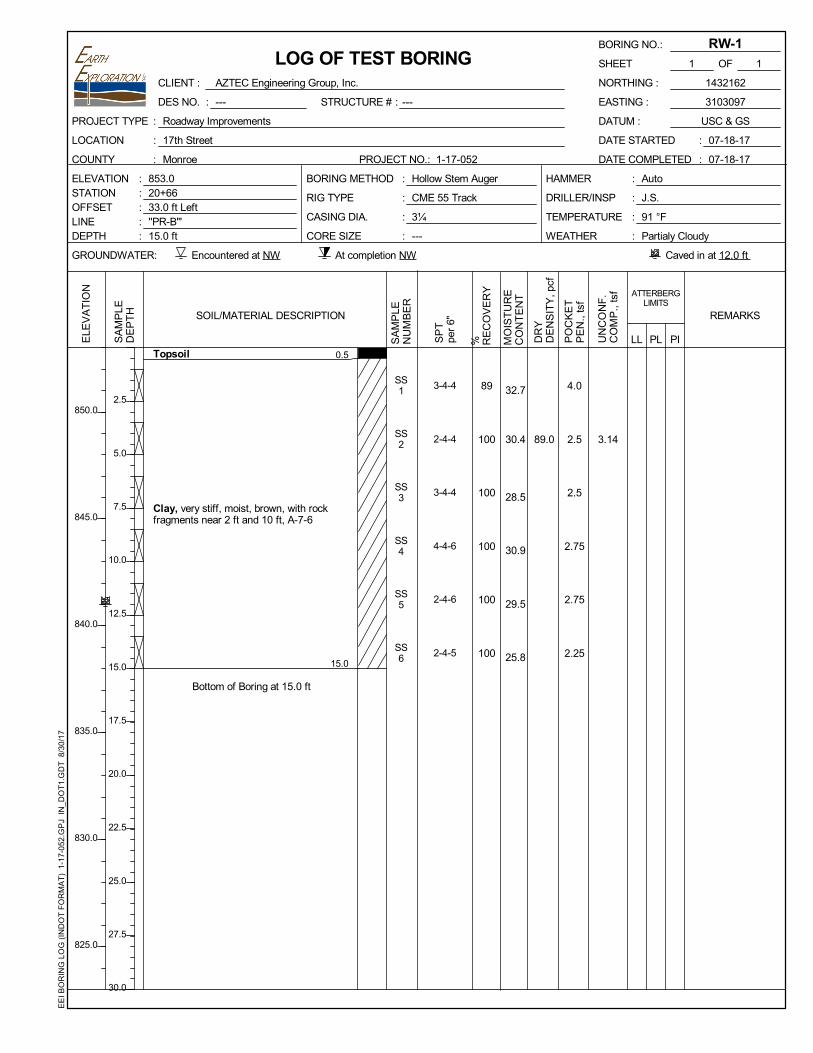
Subsurface conditions for the proposed improvements were explored by performing five soil borings
for the roadway improvements (designated RB-1 through RB-5) and three soil borings for the
retaining walls (designated RW-1 through RW-3). Auger refusal on bedrock was encountered at
Borings RB-3, RB-4, RW-2, and RW-3 prior to achieving the planned termination depth. In addition,
soundings to refusal on bedrock were performed at eight locations between the soil borings. The
number, location, and depths (where refusal was not encountered) of the borings were determined
by EEI. The exploratory locations are shown on Drawing No. 1-17-052.B1 in Appendix C. The
borings were located in the field by EEI personnel referencing identifiable features shown on the
plans. Ground surface elevations at the exploratory locations were estimated to the nearest 1 ft
based on topographic information provided on the plans. The exploratory locations and elevations
should be considered accurate only to the degree implied by the methods used.
Exploratory field activities were performed by EEI on July 18 and 20, 2017. Exploratory activities at
the soil boring locations were performed using hollow stem augers to advance the boreholes. The
soundings were performed by direct pushing or hammering a solid rod to refusal. Representative
samples of the soil conditions using Standard Penetration Test (SPT) procedures (AASHTO T 206)
were obtained at predetermined intervals. After obtaining groundwater observations, each borehole
was backfilled with auger cuttings and a bentonite chip plug was placed near the ground surface.
At the borings performed in the roadway, the surface was restored with a pavement patch.
Additional details of the drilling and sampling procedures are provided in Appendix B.
Following the field activities, the soil and rock samples were visually classified by an EEI
engineering technician and later reviewed by an EEI geotechnical engineer. After visually
classifying the soils, representative samples were selected and submitted for index property testing.
These tests included: natural moisture content (AASHTO T 265); Atterberg limits (AASHTO T 89
and T 90); soil pH; and hand penetrometer readings. The results of these tests are provided on the
Mr. Adrian Reid, P.E. August 30, 2017
AZTEC Engineering Group, Inc. Page 3
17th Street Improvements –Bloomington, IN
boring logs and/or respective laboratory reports in Appendix C. For your information, soil
descriptions on the boring logs are in general accordance with the AASHTO system and the INDOT
Standard Specifications (ISS1) (textural classification, e.g., clay, A-7-6). The boring logs represent
our interpretation of the individual samples and field logs and results of the laboratory tests. The
stratification lines on the boring logs represent the approximate boundary between soil types;
although, the transition may actually be gradual.
SITE CONDITIONS
Surface Conditions
The ground surface within the project limits is relatively flat near the western and eastern project
extents and gently to moderately sloping near the center. Grades along Line “PR-B” range from
about El. 875½ at the project start and about El. 793 at the end. In addition, a creek is present to the
south of 17th Street, with the closest proximity to the roadway being about 40 ft near Station 26+00.
At the boring locations performed in the roadways (e.g., Borings RB-1 through RB-5, and RW-3),
the surface conditions consisted of asphaltic concrete pavement (HMA) with a thickness in the
range of 6 to 16 in. At Boring RB-1, the HMA was underlain by 6 in. of a crushed stone subbase.
Also, an exception to these conditions was observed at Boring RW-3 where the HMA was found to
be about 2½ in. thick. This boring was performed in a shoulder area. The surface conditions at the
remainder of the soil boring locations consisted of about 4 to 6 in. of topsoil.
Subsurface Conditions
The subsurface profile generally consisted of cohesive soils underlain by rock. In general, the
cohesive soils were described as A-6 (clay loam and silty loam) from below the surface conditions
to depths of about 3½ to 6 ft below the existing grade. At these depths, A-7-6 clay was typically
observed to the depth at which rock was encountered or the maximum depth explored. However,
the A-7-6 soils were observed at a shallower depth at Borings RB-2, RW-1, and RW-2. The
underlying rock consisted of siltstone and limestone. Table 1 provides a summary of the depth to
rock and auger refusal at the boring and sounding locations.
Table 2: Summary of Depths to Rock and Refusal at Exploratory Locations
Boring
Location
Ground
Surface El.
Depth to
Rock (ft)
El. of
Rock
Depth of Refusal
(ft)
El. of
Refusal
RB-1 868 NO NO NO NO
RB-2 857 NO NO NO NO
RB-3 814 3.5 810.5 9 805
RB-4 800 7 793 7 793
RB-5 826 11.5 814.5 NO NO
RW-1 853 NO NO NO NO
RW-2 847 7.5 839.5 9 838
RW-3 858 10.5 847.5 10.5 847.5
1References the Indiana Department of Transportation (INDOT) Standard Specifications.
Mr. Adrian Reid, P.E. August 30, 2017
AZTEC Engineering Group, Inc. Page 4
17th Street Improvements –Bloomington, IN
Table 2: Summary of Depths to Rock and Refusal at Exploratory Locations (continued)
Boring
Location
Ground
Surface El.
Depth to
Rock (ft)
El. of
Rock
Depth of Refusal
(ft)
El. of
Refusal
S-1 857 5 852 5 852
S-2 858 12.5 845.5 12.5 845.5
S-3 857 12.5 844.5 12.5 844.5
S-4 833 10 823 10 823
S-5 844 12.5 831.5 12.5 831.5
S-6 812 2 810 2 810
S-7 810 5 805 5 805
S-8 808 5 803 5 803
NO: Not observed
It should be noted that a siltstone boulder or floater was observed at Boring RB-3 from about 3½ to
6 ft below the existing grade. Underlying this rock, A-7-6 clay was observed to a depth of about 8½
ft, where siltstone with limestone seams was observed.
The consistency of the cohesive soils was typically stiff to very stiff based on hand penetrometer
readings in the range of 1½ to 4 tons/sq. ft (tsf) and moisture contents were generally in the range
of 21 to 31 percent for the A-6 soils and 30 to 48 percent for the A-7-6 soils. A layer of medium stiff
A-6 clay loam was observed at Boring RB-5 near a depth of 2½ ft. Atterberg limit determinations
performed on the A-6 soils indicated plasticity indices (PI) of 14 and 19 with liquid limits (LL) of 31
and 38 percent indicating medium plasticity. An Atterberg limit determination performed on the
A-7-6 clay indicated a PI of 62 and a LL of 83 percent indicating very high plasticity.
As mentioned, the cohesive soils were typically underlain by siltstone and limestone. The rock was
typically soft at the surface, based on the ability to scratch recovered samples with a metallic object,
but quickly became hard based on observations and auger refusal.
It should be noted that the project lies in a general area of karst topography resulting from the
solutioning of the underlying limestone bedrock. A search on the Indiana Map GIS system indicated
that there are mapped karst features near the site. Figure 1 on the following page provides a map
of these features and was generated using IndianaMap referencing information from the Indiana
Geological Survey. However, an in-depth evaluation of the presence of karst features such as
sinkholes, caverns, or springs was not included in our scope. It is also important to recognize in
areas of karst that the bedrock surface can vary significantly and abruptly over very short distances
(e.g., pinnacles and crevices).
Mr. Adrian Reid, P.E. August 30, 2017
AZTEC Engineering Group, Inc. Page 5
17th Street Improvements –Bloomington, IN
Figure 1: Map of Karstic Features
Mr. Adrian Reid, P.E. August 30, 2017
AZTEC Engineering Group, Inc. Page 6
17th Street Improvements –Bloomington, IN
Groundwater Conditions
Groundwater level observations were made during and shortly after completion of the sampling
activities and are noted at the bottom of the boring logs. Groundwater was not observed at the soil
boring locations within the timeframe of the exploratory activities. Based on our experience, the
"piezometric" groundwater level is possible near the soil/rock interface but is likely deeper than the
maximum depth explored. As additional input, review of the Soil Survey of Monroe County suggests
that the water level remains below a depth of 6 ft throughout the year. It should be recognized that
groundwater levels either piezometric or perched can fluctuate due to changes in precipitation,
infiltration, surface run-off, and other hydrogeological factors.
DISCUSSION AND RECOMMENDATIONS
General
The subsurface conditions observed at the exploratory locations consisted of cohesive soils
exhibiting medium to very high plasticity at a shallow depth. Based upon our understanding of the
improvements and information obtained from the exploratory locations, it is our opinion that the
subsurface conditions are generally conducive for the support of the roadway improvements,
sewers, and modular block walls with reinforcement. The most critical aspect of this project, from a
geotechnical perspective, will be preparation of the subgrades for support of these elements. Given
the presence of high plasticity clay, improvement of the roadway and wall subgrades will be required.
Additional discussion and recommendations regarding these issues are provided in the following
paragraphs.
Earthwork
Subgrade Preparation
In areas to receive new pavement components and embankment fill, we recommend that topsoil,
wet or soft near-surface soils, and existing pavement components be removed from within the
construction limits. We recommend that root masses and soils containing organics be removed (grubbed) and the area regraded to avoid leaving depressions and areas that may collect water. In addition, we recommend that existing underground utilities in conflict with the proposed
construction be appropriately relocated. Where utilities are relocated, we recommend that the
resulting excavations be backfilled with B borrow in accordance with Section 203.09 of the ISS.
Once the subgrade is exposed, we recommend that the cohesive soils be proofrolled in accordance
with the ISS. The purpose of proofrolling is to provide a first-order evaluation of how the subgrade
is anticipated to react to construction traffic and gain an additional understanding of the conditions
for support of the planned improvements. We recommend that the proofrolling be observed by an
EEI geotechnical engineer or engineering technician. Based on observations at our test borings, we
anticipate that yielding subgrade conditions will be exposed during the proofroll observations where
the A-7-6 clay is present (i.e., Borings RB-2, RW-1, and RW-2) and possibly in other areas. We
anticipate that improvement of the subgrade in at-grade sections and in areas where minimal
earthwork (i.e., less than 1 ft of fill) is planned to establish the planned profile grade could be
accomplished within the range of the subgrade treatment for the pavement (i.e., Type 1B). For
areas with limited access (i.e., fill areas and retaining wall foundations), a proofroll may not be
Mr. Adrian Reid, P.E. August 30, 2017
AZTEC Engineering Group, Inc. Page 7
17th Street Improvements –Bloomington, IN
practical and evaluation of these areas may require a dynamic cone penetrometer (DCP) or probe
rod. We recommend that undistributed quantities of undercutting (maximum depth of 1½ ft) and
replacement with compacted crushed stone (INDOT No. 53) be included in the contract quantities
for the purpose of addressing poor subgrades that would not be addressed via the subgrade
treatment for pavement. A quantity of these items equal to 20 percent of the area below
embankment fill should be included as a contingency.
In areas of planned embankment fill, we recommend that soft/yielding or otherwise unstable soils
encountered during the proof-rolling operations which will not readily compact be aerated (if feasible)
to reduce the moisture content and be recompacted per the ISS. However, based on the plasticity
of the shallow soils, we anticipate that other means of stabilization of the foundation soils such as
chemical drying (ISS 217) or the undercut discussed above may be required. The final decision
regarding stabilization should be made at the time of construction, based on the observed actual
conditions after removal of the surficial elements.
Fill Placement and Compaction
Based on the anticipated earthwork requirements both cut and fill will be required to establish
proposed grades. Based on INDOT criteria, the A-7-6 soil is not suitable for use as fill. The A-6 soils
are anticipated to be suitable for reuse as fill, as needed, provided they satisfy the
recommendations for use as fill. The soils observed in the anticipated cut areas generally exhibited
moisture contents in the range of 15 to 30 percent which is above the anticipated optimum moisture
content for this soil type. Prior to use, they will require moisture conditioning in order to obtain
adequate compaction. Moisture conditioning is typically accomplished by continuously discing the
soils to reduce the moisture content and breakdown soil clods. However, this method requires
favorable weather conditions (i.e., dry warm weather) and space to spread and work the soil. If the
project timeline will not permit the use of discing or if the moisture contents during construction
exceed those observed in our laboratory evaluation, chemical drying of the soils (ISS 217) may be
utilized to dry the soils, or preconditioned imported soil may be necessary. For chemical drying, we
recommend 5 percent (by mass [tons]) of product be considered for estimating purposes. In areas
where smaller equipment will be necessary for compaction (i.e., due to space constraints), we
recommend granular soil for fill.
The maximum anticipated earth fill placement height on the project will be about 5 ft. Based on the
information obtained at the boring locations, the soil/rock interface is anticipated to be near the
embankment foundation elevation from Station 26+50 to 27+50. Therefore, we recommend that a
quantity of rock excavation (discussed later in this report) be included at this location. Standard
embankment construction practices outlined in the ISS and as discussed above should provide an
adequate subgrade for embankment construction.
Based on a review of the plans, sideslopes as steep as 3H:1V are anticipated. Global instability
of these slopes is not of concern; however the performance of these slopes will be directly
dependent on the subgrade preparation and quality of compaction achieved in the embankments,
as previously discussed. Benches should be cut into any existing slopes steeper than 6H:1V
before fill placement so as to key the new fill into the slope. Due to the relatively short
embankment heights, 6-ft wide benches (i.e., minimum) are recommended. Scarifying of the
slope will also aid in keying the new fill into the slope. Additionally, finished slopes steeper than
3H:1V can create maintenance issues as they are not accessible with conventional mowing
equipment and tend to slough (surficial). To minimize sloughing and erosion, it is important to
Mr. Adrian Reid, P.E. August 30, 2017
AZTEC Engineering Group, Inc. Page 8
17th Street Improvements –Bloomington, IN
provide adequate compaction and erosion and sloughing protection at the face of the
embankment.
Pavement Design Considerations
Based on our observations at the exploratory locations, the pavement subgrade is anticipated to
consist of cohesive soils having medium to very high plasticity. Based on the results of the resilient
modulus testing, we recommend that the information in Table 3 be considered for pavement design.
Table 3: Pavement Design Parameters
Mr for Improved Subgrade 7,500 psi
Mr for Natural Subgrade 4,000 psi
Subgrade Material Clay (A-7-6)
Depth to Water > 6 ft
Subgrade Treatment Type IB
* From field observations and the Soil Survey of Monroe County, Indiana
The use of Type IB subgrade treatment, utilizing a slurry if necessary due to the nearby residences,
will improve the subgrade’s ability to support the proposed pavements. This subgrade treatment is
recommended anticipating a full closure, allowing contractors to utilize equipment to chemically
treat large areas. If alternate MOT plans are utilized to maintain traffic during construction, the
subgrade treatment will be applied in phases, and a consistent use of Type IB subgrade treatment
may not be feasible. Type IC subgrade treatment may be utilized in isolated areas where a Type IB
treatment is not practical. However, difficulty achieving compaction in implementing a Type IC
subgrade treatment should be anticipated at locations where the A-7-6 Clay is present. As a result,
additional subgrade stabilization in addition to the subgrade treatment may be necessary
depending on the site conditions at the time of construction. If a phased MOT will be considered,
we recommend including additional quantities for undercut and No. 53 crushed stone in conjunction
with a Type IB geogrid to address these areas.
It is very important to provide positive drainage during construction before the subgrade treatment
is performed in order to reduce the risk of any wet soil conditions. We recommend that the new
storm sewers, discussed in the next section of this report, be constructed early in the project to help
improve site drainage and reduce the risk of ponding water on proposed pavement subgrades. In
addition, the subgrade should be graded at the end of each day to facilitate positive drainage. Water
infiltration into cohesive subgrade soils will reduce the life of a pavement section. Since these soils
have a low permeability, any water which may infiltrate the subgrade would affect the long-term
performance of the pavement. To reduce the impact of moisture on the pavement performance, we
recommend that the pavement surface and the subgrade be sloped to drain towards the proposed
sewers. The long-term performance of pavement is a function of routine maintenance (e.g., crack
sealing) which will be the responsibility of the owner to perform.
Modular Block Wall Considerations
Based on the soil boring information and the proposed construction, the conditions are generally
conducive for support of the proposed modular block walls. We recommend that the foundation soil
below the walls be evaluated using a dynamic cone penetrometer (DCP) and improved as
necessary in accordance with ISS 731.07. Based on the observed conditions at the test boring
Mr. Adrian Reid, P.E. August 30, 2017
AZTEC Engineering Group, Inc. Page 9
17th Street Improvements –Bloomington, IN
locations, rock is anticipated to be at or near the leveling pad elevation for the wall on the south side
of 17th Street near Station 19+50, and for the wall to the north of the path from about Station 21+00
to about Station 22+00. At these locations, rock excavation for the leveling pad and the reinforced
soil zone should be anticipated. At other locations, stiff to very stiff cohesive soils are expected to
be present and undercutting is not anticipated to be necessary provided care is taken to protect the
foundation soils from exposure to moisture and repeated construction traffic. The cohesive-type
soils anticipated at the base of the walls are moisture-sensitive and will soften if exposed to water.
Consequently, the quality of the foundation soil and the need for undercutting will be directly
contingent on the workmanship of the contractor. If undercutting is required, we recommend the
undercut areas be replaced with INDOT No. 53 crushed stone compacted to 100 percent of the
maximum dry density in accordance with AASHTO T 99. Any undercutting performed will be
required below the influence of the modular block wall fill (i.e., with a 1H:1V line of influence beyond
the front face and rear of the reinforced area).
In evaluating the design for modular block retaining walls, the external and internal stability should
be analyzed. For external stability, the following four standard modes of failure are typically
(q ≤ øqn); and 4) global stability (resistance factor of 0.65 to 0.75). To evaluate the internal stability,
three standard modes of failure are typically addressed. These include: 1) pullout of the soil
reinforcement; 2) tensile overstress of the soil reinforcement and wall connection; and 3) corrosion
(steel) and or creep (for high-density polypropylene products) of the soil reinforcement. We
understand that the wall manufacturer will evaluate the internal stability of the wall system, including
that of any gravity-type wall elements.
Analyses of a cut condition and a fill condition were performed considering the respective maximum
retained heights, foundation soils consisting of stiff cohesive soil, and with traffic surcharge loading,
where appropriate. The analysis for over-turning and sliding considered the maximum height of the
retaining walls and a minimum width of 0.7 times the height or 6 ft (whichever is greater). Our
analysis indicated adequate resistance to sliding, eccentricity, and bearing, provided the foundation
is adequately prepared and improved, where necessary, as described. Provided the subgrade and
foundation is prepared as discussed (including the undercutting), the global stability indicated the
proposed geometry exhibited an acceptable factors of safety. A factored bearing resistance of
5,000 psf for all of the walls is acceptable. The same resistance is recommended for walls founded
on rock and soil to reduce the risk of a bearing failure in the soil. Due to the relatively shallow
bedrock in conjunction with the stiff to very stiff (overconsolidated) soils, consolidation settlement of
the foundation soil is not of concern.
Due to the cut condition and the location of the creek, we recommend that the structure backfill be
INDOT No. 8 crushed stone and that adequate drainage be provided (with cleanouts) in the
structure backfill and at the base of the modular block walls in accordance with INDOT Design
Memorandum No. 17-03. Also, in accordance with Chapter 11 of AASHTO, we recommend a 4-ft
wide horizontal bench be constructed at the base of modular block walls constructed on a slope.
The recommended embedment depth of the leveling course is also based on the slope. Refer to
Chapter 11 for additional commentary on geometric requirements. For the fill wall, we recommend
scour and erosion protection be provided via appropriately sized riprap.
East of Station 23+50, the walls planned on the north side of 17th Street and the path are in
residential yards, many of which feature mature trees. It is important to remember that construction
of a modular block wall in a cut condition requires excavation for the reinforced zone and excavation
Mr. Adrian Reid, P.E. August 30, 2017
AZTEC Engineering Group, Inc. Page 10
17th Street Improvements –Bloomington, IN
behind this zone to create a safe slope during construction. The wall near Station 27+00 is planned
to be about 8 ft tall and the house on this property is located about 20 ft behind the wall. Considering
the estimate of reinforcement length and a typical 1H:1V cutback slope during construction, the
construction geometry is anticipated to come close to the houses. We recommend that you
evaluate the walls and construction excavation geometry relative to the location of existing mature
trees and houses. We recommend that EEI be retained to evaluate any changes in the design. An
alternate wall type (e.g., cast-in-place concrete, gravity block) and/or detailed evaluation of cut
slopes may be necessary.
Storm Sewer Considerations
We understand that invert subgrades for the sewers are planned to be established within about 4 ft
of the existing ground surface. Based on our observations at the exploratory locations, relatively stiff
cohesive soils are anticipated to be encountered at the subgrade. However, as evidenced by the
observations at Boring RB-3 and the variation in the depth to rock in Table 2, rock excavation will
likely be necessary in isolated locations during the construction of the sewer. In our opinion, these
conditions are generally adequate for support of the pipes (i.e., the net load on the supporting
conditions is anticipated to be nominal [possibly less than the overburden]). The condition of the
subgrade will be, in part, a function of the care and workmanship of the contractor in protecting the
subgrade from water. The cohesive soils observed at the test boring locations are
moisture-sensitive and will soften when exposed to water. If soft soils are encountered at the base
of the trench excavations or the condition of the subgrade deteriorates in the presence of moisture,
it is our opinion they should be removed and replaced with compacted structure backfill material to
achieve a stable base. Although not anticipated, if the use of structure backfill is not feasible due to
the depth of unstable materials, the use of geogrid and/or compacted crushed aggregate may be
required to stabilize the trench. In this case, a minimum of 2 ft of the soft soils should be removed
prior to stabilization.
In our opinion, a minimum 6-in. thick bedding layer consisting of structure backfill material should
be provided for pipe support. This includes areas where rock is present at the invert. Since the pipes
are anticipated to be located beneath or adjacent to the proposed roadways, the trenches should
be backfilled to grade with structure backfill material. In our opinion, the structure backfill material
should be compacted to 95 percent of maximum dry density obtained in accordance with AASHTO
T 99 and INDOT Specifications. Hand or remote guided vibratory compactors are recommended for
compacting the bedding material and material on either side of the pipe. The first several lifts of
backfill over the pipe should also be compacted with small vibratory compactors to assure proper
compaction is achieved and to prevent damage to the pipe from heavier, high-energy compactors.
Excavations and Dewatering
We recommend that excavated soil not be stockpiled immediately adjacent to the top of the
excavation nor should equipment be allowed to operate too closely to excavations. Furthermore, all
excavations should conform to Occupational Safety and Health Administration (OSHA)
requirements (i.e., 29 CFR Part 1926). Excavation safety is solely the responsibility of the
contractor.
As mentioned previously, auger refusal on siltstone and limestone bedrock was encountered at
several boring locations along the proposed roadway and modular block walls. At locations where
the hollow-stem augers were able to penetrate the rock, the rock at this location may be rippable
Mr. Adrian Reid, P.E. August 30, 2017
AZTEC Engineering Group, Inc. Page 11
17th Street Improvements –Bloomington, IN
and/or could possibly be broken with a hydraulic hammer or with conventional earthwork equipment.
However due to variations in the rock that were observed at the test boring locations and that are
inherent with the geology of Bloomington, some areas may not be rippable with conventional
earthwork equipment. The actual method of rock removal to be used cannot be speculated with
certainty. However where hard rock is encountered, from experience, other methods have included
hydraulic hammers and heavier mechanical equipment. We recommend that the quantities for rock
excavation be based on the top of rock and not on the depth of auger refusal. Rock excavation is
anticipated along portions of the walls west of Station 22+00 and, possibly, near the toe of the
embankment fill planned from Station 26+50 to 27+50.
For shallow excavations in the observed cohesive soils, dewatering is anticipated to consist of
traditional pumps and filtered sumps possibly in combination with collection trenches provided the
level of the creek does not rise.
CONCLUDING REMARKS
In closing, EEI's professional services were performed, our findings obtained, and our preliminary
recommendations prepared in accordance with generally and currently accepted geotechnical
engineering practices. This warranty is in lieu of all other warranties either expressed or implied.
We appreciate the opportunity to provide our services to you on this project. Please contact our
office if you have any questions or need further assistance with the project.
Sincerely,
EARTH EXPLORATION, INC.
Kellen P. Heavin, P.E.
Senior Geotechnical Engineer
Curtis R. Bradburn, P.E.
Senior Geotechnical Engineer
Attachments – APPENDIX A - Important Information about This Geotechnical Engineering Report APPENDIX B - Field Methods for Exploring and Sampling Soils and Rock APPENDIX C - Exploratory Location Plan (Drawing No. 1-17-052.B1) Log of Test Boring - General Notes Log of Test Boring (8) Summary of Soundings Unconfined Compression Test (2)
APPENDIX A
IMPORTANT INFORMATION ABOUT THISGEOTECHNICAL ENGINEERING REPORT
Geotechnical-Engineering ReportImportant Information about This
Subsurface problems are a principal cause of construction delays, cost overruns, claims, and disputes.
While you cannot eliminate all such risks, you can manage them. The following information is provided to help.
The Geoprofessional Business Association (GBA) has prepared this advisory to help you – assumedly a client representative – interpret and apply this geotechnical-engineering report as effectively as possible. In that way, clients can benefit from a lowered exposure to the subsurface problems that, for decades, have been a principal cause of construction delays, cost overruns, claims, and disputes. If you have questions or want more information about any of the issues discussed below, contact your GBA-member geotechnical engineer. Active involvement in the Geoprofessional Business Association exposes geotechnical engineers to a wide array of risk-confrontation techniques that can be of genuine benefit for everyone involved with a construction project.
Geotechnical-Engineering Services Are Performed for Specific Purposes, Persons, and ProjectsGeotechnical engineers structure their services to meet the specific needs of their clients. A geotechnical-engineering study conducted for a given civil engineer will not likely meet the needs of a civil-works constructor or even a different civil engineer. Because each geotechnical-engineering study is unique, each geotechnical-engineering report is unique, prepared solely for the client. Those who rely on a geotechnical-engineering report prepared for a different client can be seriously misled. No one except authorized client representatives should rely on this geotechnical-engineering report without first conferring with the geotechnical engineer who prepared it. And no one – not even you – should apply this report for any purpose or project except the one originally contemplated.
Read this Report in FullCostly problems have occurred because those relying on a geotechnical-engineering report did not read it in its entirety. Do not rely on an executive summary. Do not read selected elements only. Read this report in full.
You Need to Inform Your Geotechnical Engineer about ChangeYour geotechnical engineer considered unique, project-specific factors when designing the study behind this report and developing the confirmation-dependent recommendations the report conveys. A few typical factors include: • the client’s goals, objectives, budget, schedule, and risk-management preferences; • the general nature of the structure involved, its size, configuration, and performance criteria; • the structure’s location and orientation on the site; and • other planned or existing site improvements, such as retaining walls, access roads, parking lots, and underground utilities.
Typical changes that could erode the reliability of this report include those that affect:• the site’s size or shape;• the function of the proposed structure, as when it’s changed from a parking garage to an office building, or from a light-industrial plant to a refrigerated warehouse;• the elevation, configuration, location, orientation, or weight of the proposed structure;• the composition of the design team; or• project ownership.
As a general rule, always inform your geotechnical engineer of project changes – even minor ones – and request an assessment of their impact. The geotechnical engineer who prepared this report cannot accept responsibility or liability for problems that arise because the geotechnical engineer was not informed about developments the engineer otherwise would have considered.
This Report May Not Be ReliableDo not rely on this report if your geotechnical engineer prepared it:• for a different client;• for a different project;• for a different site (that may or may not include all or a portion of the original site); or • before important events occurred at the site or adjacent to it; e.g., man-made events like construction or environmental remediation, or natural events like floods, droughts, earthquakes, or groundwater fluctuations.
Note, too, that it could be unwise to rely on a geotechnical-engineering report whose reliability may have been affected by the passage of time, because of factors like changed subsurface conditions; new or modified codes, standards, or regulations; or new techniques or tools. If your geotechnical engineer has not indicated an “apply-by” date on the report, ask what it should be, and, in general, if you are the least bit uncertain about the continued reliability of this report, contact your geotechnical engineer before applying it. A minor amount of additional testing or analysis – if any is required at all – could prevent major problems.
Most of the “Findings” Related in This Report Are Professional OpinionsBefore construction begins, geotechnical engineers explore a site’s subsurface through various sampling and testing procedures. Geotechnical engineers can observe actual subsurface conditions only at those specific locations where sampling and testing were performed. The data derived from that sampling and testing were reviewed by your geotechnical engineer, who then applied professional judgment to form opinions about subsurface conditions throughout the site. Actual sitewide-subsurface conditions may differ – maybe significantly – from those indicated in this report. Confront that risk by retaining your geotechnical engineer to serve on the design team from project start to project finish, so the individual can provide informed guidance quickly, whenever needed.
This Report’s Recommendations Are Confirmation-DependentThe recommendations included in this report – including any options or alternatives – are confirmation-dependent. In other words, they are not final, because the geotechnical engineer who developed them relied heavily on judgment and opinion to do so. Your geotechnical engineer can finalize the recommendations only after observing actual subsurface conditions revealed during construction. If through observation your geotechnical engineer confirms that the conditions assumed to exist actually do exist, the recommendations can be relied upon, assuming no other changes have occurred. The geotechnical engineer who prepared this report cannot assume responsibility or liability for confirmation-dependent recommendations if you fail to retain that engineer to perform construction observation.
This Report Could Be MisinterpretedOther design professionals’ misinterpretation of geotechnical-engineering reports has resulted in costly problems. Confront that risk by having your geotechnical engineer serve as a full-time member of the design team, to: • confer with other design-team members, • help develop specifications, • review pertinent elements of other design professionals’ plans and specifications, and • be on hand quickly whenever geotechnical-engineering guidance is needed. You should also confront the risk of constructors misinterpreting this report. Do so by retaining your geotechnical engineer to participate in prebid and preconstruction conferences and to perform construction observation.
Give Constructors a Complete Report and GuidanceSome owners and design professionals mistakenly believe they can shift unanticipated-subsurface-conditions liability to constructors by limiting the information they provide for bid preparation. To help prevent the costly, contentious problems this practice has caused, include the complete geotechnical-engineering report, along with any attachments or appendices, with your contract documents, but be certain to note conspicuously that you’ve included the material for informational purposes only. To avoid misunderstanding, you may also want to note that “informational purposes” means constructors have no right to rely on the interpretations, opinions, conclusions, or recommendations in the report, but they may rely on the factual data relative to the specific times, locations, and depths/elevations referenced. Be certain that constructors know they may learn about specific project requirements, including options selected from the report, only from the design drawings and specifications. Remind constructors that they may
perform their own studies if they want to, and be sure to allow enough time to permit them to do so. Only then might you be in a position to give constructors the information available to you, while requiring them to at least share some of the financial responsibilities stemming from unanticipated conditions. Conducting prebid and preconstruction conferences can also be valuable in this respect.
Read Responsibility Provisions CloselySome client representatives, design professionals, and constructors do not realize that geotechnical engineering is far less exact than other engineering disciplines. That lack of understanding has nurtured unrealistic expectations that have resulted in disappointments, delays, cost overruns, claims, and disputes. To confront that risk, geotechnical engineers commonly include explanatory provisions in their reports. Sometimes labeled “limitations,” many of these provisions indicate where geotechnical engineers’ responsibilities begin and end, to help others recognize their own responsibilities and risks. Read these provisions closely. Ask questions. Your geotechnical engineer should respond fully and frankly.
Geoenvironmental Concerns Are Not CoveredThe personnel, equipment, and techniques used to perform an environmental study – e.g., a “phase-one” or “phase-two” environmental site assessment – differ significantly from those used to perform a geotechnical-engineering study. For that reason, a geotechnical-engineering report does not usually relate any environmental findings, conclusions, or recommendations; e.g., about the likelihood of encountering underground storage tanks or regulated contaminants. Unanticipated subsurface environmental problems have led to project failures. If you have not yet obtained your own environmental information, ask your geotechnical consultant for risk-management guidance. As a general rule, do not rely on an environmental report prepared for a different client, site, or project, or that is more than six months old.
Obtain Professional Assistance to Deal with Moisture Infiltration and MoldWhile your geotechnical engineer may have addressed groundwater, water infiltration, or similar issues in this report, none of the engineer’s services were designed, conducted, or intended to prevent uncontrolled migration of moisture – including water vapor – from the soil through building slabs and walls and into the building interior, where it can cause mold growth and material-performance deficiencies. Accordingly, proper implementation of the geotechnical engineer’s recommendations will not of itself be sufficient to prevent moisture infiltration. Confront the risk of moisture infiltration by including building-envelope or mold specialists on the design team. Geotechnical engineers are not building-envelope or mold specialists.
Copyright 2016 by Geoprofessional Business Association (GBA). Duplication, reproduction, or copying of this document, in whole or in part, by any means whatsoever, is strictly prohibited, except with GBA’s specific written permission. Excerpting, quoting, or otherwise extracting wording from this document is permitted only with the express written permission of GBA, and only for purposes of scholarly research or book review. Only members of GBA may use this document or its wording as a complement to or as an element of a report of any
kind. Any other firm, individual, or other entity that so uses this document without being a GBA member could be committing negligent
FIELD METHODS FOR EXPLORING AND SAMPLING SOILS AND ROCK
FIELD METHODS FOR EXPLORING AND SAMPLING SOILS AND ROCK
A. Boring Procedures Between Samples
The boring is extended downward, between samples, by a hollow stem auger (AASHTO*Designation T251), continuous flight auger, driven and washed-out casing, or rotary boring withdrilling mud or water.
B. Standard Penetration Test and Split-Barrel Sampling of Soils(AASHTO* Designation: T206)
This method consists of driving a 2-in. outside diameter split-barrel sampler using a 140-lbweight falling freely through a distance of 30 in. The sampler is first seated 6 in. into the materialto be sampled and then driven 12 in. The number of blows required to drive the sampler thefinal 12 in. is recorded on the Log of Test Boring and known as the Standard PenetrationResistance or N-value. Recovered samples are first classified as to texture by the fieldpersonnel. Later in the laboratory, the field classification is reviewed by a geotechnical engineerwho observes each sample.
C. Thin-walled Tube Sampling of Soils(AASHTO* Designation: T207)
This method consists of hydraulically pushing a 2-in. or 3-in. outside diameter thin wall tube intothe soil, usually cohesive types. Relatively undisturbed samples are recovered.
D. Soil Investigation and Sampling by Auger Borings(AASHTO* Designation: T203)
This method consists of augering a hole and removing representative soil samples from theauger flight or bucket at 5-ft intervals or with each change in the substrata. Relatively disturbedsamples are obtained and its use is therefore limited to situations where it is satisfactory todetermine approximate subsurface profile.
E. Diamond Core Drilling for Site Investigation(AASHTO* Designation: T225)
This method consists of advancing a hole in rock or other hard strata by rotating downward asingle tube or double tube core barrel equipped with a cutting bit. Diamond, tungsten carbide, orother cutting agents may be used for the bit. Wash water is used to remove the cuttings.Normally, a 3-in. outside diameter by 2-in. inside diameter coring bit is used unless otherwisenoted. The rock or hard material recovered within the core barrel is examined in the field andlaboratory. Cores are stored in partitioned boxes and the length of recovered material isexpressed as a percentage of the actual distance penetrated.
* American Association of State Highway and Transportation Officials, Washington D.C.
APPENDIX C
EXPLORATORY LOCATION PLAN (Drawing No. 1-17-052.B1)
LOG OF TEST BORING - GENERAL NOTES
LOG OF TEST BORING (8)
SUMMARY OF SOUNDINGS
UNCONFINED COMPRESSION TEST (2)
LIN
DB
ER
GH
D
R
LIS
MO
RE
D
R
CR
ES
CE
NT
R
D
AR
LIN
GT
ON
P
AR
K D
R
17th ST
RB-1
RB-5
RW-1
RW-2
RW-3
S-1S-2 S-3
S-4
S-5
10+00
11+00
12+0013+00
14+0015+00
16+0017+00
18+0019+00
20+0021+00
22+00
23+00
RB-2
LINE "PR-B"
BR
IC
K D
R
RB-3
RB-4
S-6
S-7
S-8
24+0025+00
26+00
27+0028+
00 29+00
30+00
31+00
3
2
+
0
0
33+
00
17th ST
LINE "PR-B"
NOTESLEGEND
and Designation
Test Boring Location RB-1
VICINITY MAP
N.T.S.
1. Base map developed from an electronic file provided by Aztec Engineering Group, Inc. on July 27, 2017.
2. Vicinity map generated using commercially-available software by DeLorme (Street Atlas USA ver. 8.0).
3. Borings and soundings were located in the field by Earth Exploration, Inc. on June 20, 2017.
4. Ground surface elevations at the test boring locations were interpolated to the nearest 1 ft based on topographic
information provided on the previously mentioned plan.
5. Exploratory locations are approximate.
PROJECT:
LOCATION:
CLIENT:
EEI PROJECT NO.:
SCALE:
17th Street Improvements
Bloomington, Indiana
Aztec Engineering Group, Inc.
1-17-052
1" = 100'
PROJECT ENG:
APPROVED BY:
DRAWN BY:
DATE:
DRAWING NO.:
KPH
MSW
JBF
8/20/17
1-17-052.B1
EXPLORATORY LOCATION PLAN
MA
TC
HLIN
E S
TA
. 23+
50 "P
R-B
"
MA
TC
HLIN
E S
TA
. 23+
50 "P
R-B
"
and Designation
Sounding Location S-1
LOG OF TEST BORING – GENERAL NOTES
DESCRIPTIVE CLASSIFICATION SYMBOLS
GRAIN SIZE TERMINOLOGY DRILLING AND SAMPLING
Soil Fraction Particle Size US Standard Sieve Size
Boulders ................ Larger than 75 mm ............... Larger than 3”Gravel .................... 4.76 mm to 75 mm ............... #10 to 75 mmSand: Coarse ..... 2.00 to 4.76 mm ................... #40 to #10
Fine ......... 0.075 to 0.42 mm ................. #200 to #40Silt ......................... 0.002 to 0.075 mm ............... Smaller than #200Clay ....................... Smaller than 0.002 mm …….. Smaller than #200
GENERAL TERMINOLOGY RELATIVE DENSITY
Physical Characteristics Term “N” Value- Color, moisture, grain shape
fineness, etc. Very loose …………….............. 0 – 5Major Constituents Loose …………………………… 6 – 10- Clay silt, sand, gravel Medium dense ………………… 11 – 30Structure Dense …………………………… 31 – 50- Laminated, varved, fibrous, Very Dense …………………….. 51+stratified, cemented, fissured,etc.
Stiff ……………………………. 11 - 15 LABORATORY TESTSDefining Range by Very Stiff ……………………… 16 - 30
Term % of Weight Hard …………………………… 31+
Trace ………………. 1 – 10%
Little ……………….. 11 – 20% PLASTICITYSome ……………… 21 – 35%And ……………….. 36 – 50% Term Plastic Index
None to slight ……………. 0 – 4
ORGANIC CONTENT BY Slight ……………………… 5 – 7
COMBUSTION METHOD Medium …………………… 8 – 22High/Very High …………... Over 22
Soil Description LOI
WATER LEVELw/ organic matter ……….…. 4 – 15 % MEASUREMENTOrganic Soil (A-8) …………. 16 – 30%Peat (A-8) ………………….. More than 30%
Note: Water level measurements shownThe penetration resistance, N, is the summation of the number of blows on the boring logs represent conditionsrequired to effect two successive 6-in. penetrations of the 2-in. split-barrel at the time indicated and may not reflectsampler. The sampler is driven with a 140-lb weight falling 30 in. and is static levels, especially in cohesive soils.seated to a depth of 6 in. before commencing the standard penetration test.
Parameter A=4 km B=26 km C=32 km D=36 km E=43 kmStation ID IN6580 IN1869 IN0784 IN8036 IN6705Elevation, m 603 678 771 510 520Degree-Days >10 C 2946 3185 2936 3091 3120Low Air Temperature, C -23.3 -21.6 -21.6 -22.5 -23.9Low Air Temp. Std Dev 4.4 4.1 3.7 4.3 5
Input Data
Latitude, Degree 38.91Yearly Degree-Days>10C 3056Lowest Yearly Air Temp., Deg. C -22.6Low Temp. Std. Dev., Deg. C 4.3Base HT PG 58
Traffic Adjustments for HT
Desired Reliability, Percent 98Traffic Loading, Million ESAL Up to 3 M. ESALTraffic Speed FastHigh Temp. Adjustment 0.0
PG Temperature HIGH LOWPG Temp. at 50% Reliability 57.0 -15.1PG Temp. at Desired Reliability 59.2 -22.8Adjustments for Traffic 0 Adjustments for Depth 0.0 0.0Adjusted PG Temperature 59.2 -22.8Selected PG Binder Grade 64 -28
Layer type Material Type Thickness (in)Flexible 9.5mm Surface PG64 1.5Flexible 19mm Intermediate PG64 2.5Flexible 19mm Base PG64 3.0NonStabilized CA No 53 3.0
Subgrade Improved subgrade type IB 14.0
Subgrade Clay (A-7-6) Semi-infinite
Volumetric at Construction:Effective binder content (%) 11.6
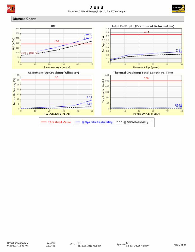
7 on 3File Name: C:\My ME Design\Projects\17th St\7 on 3.dgpx
Report generated on: 9/26/2017 12:45 PM Page 4 of 24
by: on: 8/15/2016 4:08 PM on: 8/15/2016 4:08 PM
by: Created ApprovedVersion: 2.3.0+65
AADTT (Average Annual Daily Truck Traffic) Growth* Traffic cap is not enforced
7 on 3File Name: C:\My ME Design\Projects\17th St\7 on 3.dgpx
Report generated on: 9/26/2017 12:45 PM Page 5 of 24
by: on: 8/15/2016 4:08 PM on: 8/15/2016 4:08 PM
by: Created ApprovedVersion: 2.3.0+65
Climate Inputs
Climate Data Sources:
Climate Station Cities: Location (lat lon elevation(ft))38.04300 -87.53700 400EVANSVILLE, IN
Monthly Climate Summary:
Annual Statistics:
Mean annual air temperature (ºF) 56.72Mean annual precipitation (in) 43.98Freezing index (ºF - days) 294.36Average annual number of freeze/thaw cycles: 56.22 Water table depth
(ft)6.00
7 on 3File Name: C:\My ME Design\Projects\17th St\7 on 3.dgpx
Report generated on: 9/26/2017 12:45 PM Page 6 of 24
by: on: 8/15/2016 4:08 PM on: 8/15/2016 4:08 PM
by: Created ApprovedVersion: 2.3.0+65
< -13º F
Hourly Air Temperature Distribution by Month:
-13º F to -4º F -4º F to 5º F 5º F to 14º F 14º F to 23º F 23º F to 32º F 32º F to 41º F 41º F to 50º F
59º F to 68º F50º F to 59º F 68º F to 77º F 77º F to 86º F 86º F to 95º F 95º F to 104º F 104º F to 113º F
> 113º F
7 on 3File Name: C:\My ME Design\Projects\17th St\7 on 3.dgpx
Report generated on: 9/26/2017 12:45 PM Page 7 of 24
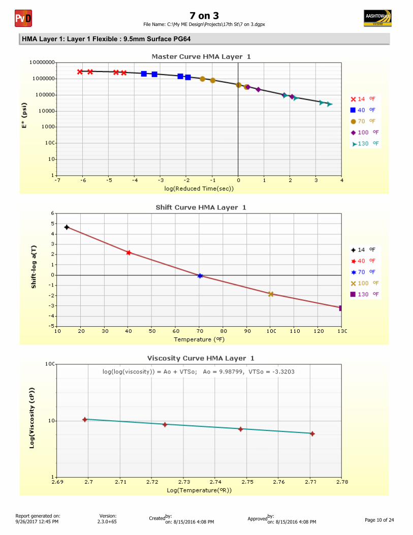
T ( ºF) 0.1 Hz10 199820140 133785670 185430100 40801130 21241
25 Hz32880652273465923021312269119675
1 Hz2420191170877943198510052238909
10 Hz2664791199697574393422872085495
Asphalt Dynamic Modulus (Input Level: 1)
AsphaltThickness (in) 1.5Unit weight (pcf) 142.6Poisson's ratio Is Calculated? False
Ratio 0.35Parameter A - Parameter B -
General Info
Name ValueReference temperature (ºF) 70Effective binder content (%) 11.6Air voids (%) 8Thermal conductivity (BTU/hr-ft-ºF) 0.63Heat capacity (BTU/lb-ºF) 0.31
Field ValueDisplay name/identifier 9.5mm Surface PG64
Description of object
AuthorDate Created 10/30/2010 1:00:00 AMApproverDate approved 10/30/2010 1:00:00 AMStateDistrictCountyHighwayDirection of TravelFrom station (miles)To station (miles)ProvinceUser defined field 1User defined field 2User defined field 3Revision Number 0
Identifiers
7 on 3File Name: C:\My ME Design\Projects\17th St\7 on 3.dgpx
Report generated on: 9/26/2017 12:45 PM Page 17 of 24
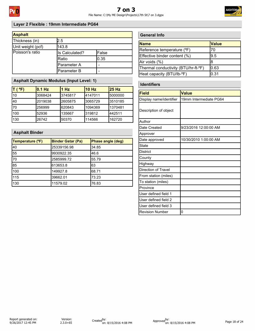
T ( ºF) 0.1 Hz10 306842440 201903870 256999100 52936130 26742
25 Hz500000035101851370481442511162720
1 Hz3745817260587562084313566750370
10 Hz414701130657291094369319812114566
Asphalt Dynamic Modulus (Input Level: 1)
AsphaltThickness (in) 2.5Unit weight (pcf) 143.8Poisson's ratio Is Calculated? False
Ratio 0.35Parameter A - Parameter B -
General Info
Name ValueReference temperature (ºF) 70Effective binder content (%) 9.5Air voids (%) 8Thermal conductivity (BTU/hr-ft-ºF) 0.63Heat capacity (BTU/lb-ºF) 0.31
Field ValueDisplay name/identifier 19mm Intermediate PG64
Description of object
AuthorDate Created 9/23/2016 12:00:00 AMApproverDate approved 10/30/2010 1:00:00 AMStateDistrictCountyHighwayDirection of TravelFrom station (miles)To station (miles)ProvinceUser defined field 1User defined field 2User defined field 3Revision Number 0
Identifiers
7 on 3File Name: C:\My ME Design\Projects\17th St\7 on 3.dgpx
Report generated on: 9/26/2017 12:45 PM Page 18 of 24
T ( ºF) 0.1 Hz10 309635540 202973670 253654100 51493130 25826
25 Hz500000035461581372761438810159924
1 Hz3785826262549061754913312648970
10 Hz419312830931901093998316229112241
Asphalt Dynamic Modulus (Input Level: 1)
AsphaltThickness (in) 3.0Unit weight (pcf) 143.8Poisson's ratio Is Calculated? False
Ratio 0.35Parameter A - Parameter B -
General Info
Name ValueReference temperature (ºF) 70Effective binder content (%) 9.53Air voids (%) 8Thermal conductivity (BTU/hr-ft-ºF) 0.63Heat capacity (BTU/lb-ºF) 0.31
Field ValueDisplay name/identifier 19mm Base PG64
Description of object
AuthorDate Created 10/30/2010 1:00:00 AMApproverDate approved 10/30/2010 1:00:00 AMStateDistrictCountyHighwayDirection of TravelFrom station (miles)To station (miles)ProvinceUser defined field 1User defined field 2User defined field 3Revision Number 0
Identifiers
7 on 3File Name: C:\My ME Design\Projects\17th St\7 on 3.dgpx
Report generated on: 9/26/2017 12:45 PM Page 19 of 24
Use Correction factor for NDT modulus? - NDT Correction Factor: -
Field ValueDisplay name/identifier CA No 53
Description of object Separation layer
Author AASHTODate Created 1/1/2011 12:00:00 AMApproverDate approved 1/1/2011 12:00:00 AMStateDistrictCountyHighwayDirection of TravelFrom station (miles)To station (miles)ProvinceUser defined field 1User defined field 2User defined field 3Revision Number 0
Identifiers
7 on 3File Name: C:\My ME Design\Projects\17th St\7 on 3.dgpx
Report generated on: 9/26/2017 12:45 PM Page 20 of 24
Use Correction factor for NDT modulus? - NDT Correction Factor: -
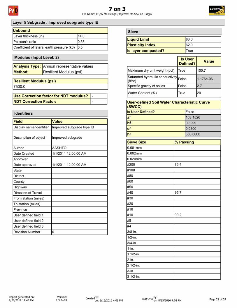
Field ValueDisplay name/identifier Improved subgrade type IB
Description of object Improved subgrade
Author AASHTODate Created 1/1/2011 12:00:00 AMApproverDate approved 1/1/2011 12:00:00 AMStateDistrictCountyHighwayDirection of TravelFrom station (miles)To station (miles)ProvinceUser defined field 1User defined field 2User defined field 3Revision Number 0
Identifiers
7 on 3File Name: C:\My ME Design\Projects\17th St\7 on 3.dgpx
Report generated on: 9/26/2017 12:45 PM Page 21 of 24
Use Correction factor for NDT modulus? - NDT Correction Factor: -
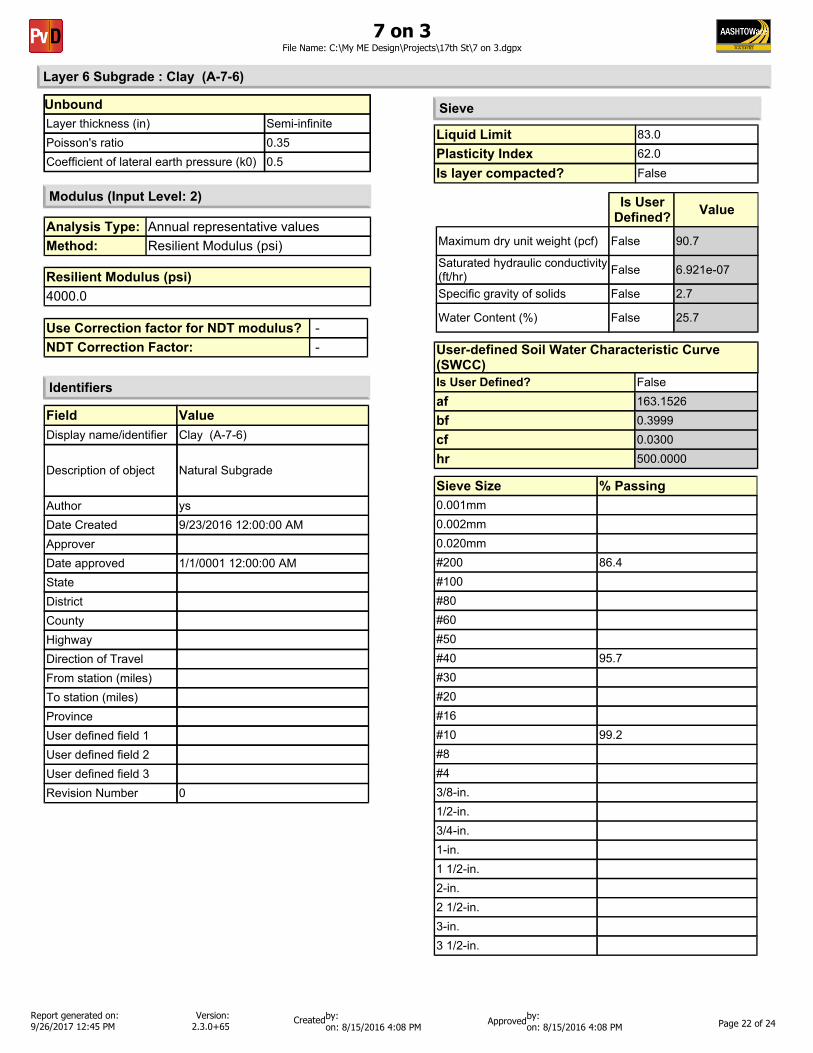
Field ValueDisplay name/identifier Clay (A-7-6)
Description of object Natural Subgrade
Author ysDate Created 9/23/2016 12:00:00 AMApproverDate approved 1/1/0001 12:00:00 AMStateDistrictCountyHighwayDirection of TravelFrom station (miles)To station (miles)ProvinceUser defined field 1User defined field 2User defined field 3Revision Number 0
Identifiers
7 on 3File Name: C:\My ME Design\Projects\17th St\7 on 3.dgpx
Report generated on: 9/26/2017 12:45 PM Page 22 of 24
by: on: 8/15/2016 4:08 PM on: 8/15/2016 4:08 PM
by: Created ApprovedVersion: 2.3.0+65
Calibration Coefficients
k1: 0.007566k2: 3.9492k3: 1.281Bf1: 1Bf2: 1Bf3: 1
AC Fatigue
AC Layer K1:-3.35412 K2:1.5606 K3:0.4791 Br1:0.07 Br2:1.9 Br3:0.40.24*Pow(RUT,0.8026)+0.001
AC Rutting
AC Rutting Standard Deviation
Level 1 K: 1.5Level 2 K: 0.5Level 3 K: 1.5
Level 1 Standard Deviation: 0.1468 * THERMAL + 65.027Level 2 Standard Deviation: 0.2841 *THERMAL + 55.462 Level 3 Standard Deviation: 0.3972 * THERMAL + 20.422
Thermal Fracture
k1: 1 k2: 1 Bc1: 1 Bc2:1
CSM Fatigue
7 on 3File Name: C:\My ME Design\Projects\17th St\7 on 3.dgpx
Report generated on: 9/26/2017 12:45 PM Page 23 of 24