Geothermal in Oregon Where it is being used Where it can be used Compiled by Tonya “Toni”Boyd Geo-Heat Center Oregon Institute of Technology 3201 Camus Drive Klamath Falls, OR 97601 541-885-1750 [email protected]ADRIAN ADEL BEULAH BONANZA BURNS CRANE FIELDS GOVERNMENT CAMP JEFFERSON KEHNEETA KLAMATH FALLS LORELLA McCREDIE SPRINGS HAINES HARNEY BREITENBUSH LAWEN LAKEVIEW LEHMAN SPRINGS McKENZIE NEW PINE CREEK NYSSA ONTARIO PAISLEY PONDOSA POWELL BUTTE RIVERSIDE SILVERTON UNION VALE SUMPTER HARPER Thermal well Thermal spring Temp, o C / Depth, m Flow, L/min / TDS, mg/L LEGEND 121 o / 1426 416 / 72 o / 2379 / 89 o / 310 3408 / 56 o / / 58 o / 1498 / 89 o / 130 395 / 57 o / 461 / 73 o / 75 / 61 o / / 85 o / 6155 / 61 o / 200 / 57 o / 37.5 1150 / 57 o / 105 / 60 o / 50 / 168 / 3064 / 115 o / 81 2914 / 70 o / 125 550 / 84 o / 478 / 79 o / 410 60 / 63 o / 225 / 72 o / 287 1000 / 71 o / 696 / 57 o / 559 35 / 82 o / 50 700 / 97 o / 20 / 89 o / 170 5000 / 113 o / 184 6539 / 111 o / 210 75 / 121 o / 196 60 / 61 o / 150 / 105 o / 200 8377 / 902 94 o / 70 / HOT SPRING Communities with Geothermal Direct- Use Development Potential
Transcript
Geothermal in Oregon
Where it is being used
Where it can be used
Compiled by Tonya “Toni”Boyd Geo-Heat Center Oregon Institute of Technology 3201 Camus Drive Klamath Falls, OR 97601 541-885-1750 [email protected]
ADRIAN
ADEL
BEULAH
BONANZA
BURNS
CRANE
FIELDS
GOVERNMENTCAMP
JEFFERSON
KEHNEETA
KLAMATHFALLS
LORELLA
McCREDIESPRINGS
HAINES
HARNEY
BREITENBUSH
LAWEN
LAKEVIEW
LEHMANSPRINGS
McKENZIE
NEW PINE CREEK
NYSSA
ONTARIO
PAISLEY
PONDOSA
POWELL BUTTE
RIVERSIDE
SILVERTON
UNION
VALE
SUMPTER
HARPER
Thermal well
Thermal springTemp,oC / Depth, m Flow, L/min / TDS, mg/L
LEGEND
121o / 1426416 /
72o / 2379 /
89o / 3103408 /
56o / /
58o / 1498 /
89o / 130395 /
57o / 461 /
73o / 75 /
61o / /
85o / 6155 /
61o / 200 /
57o / 37.51150 /
57o / 105 /
60o / 50 /
168o / 3064 /
115o / 812914 /
70o / 125550 /
84o / 478 /
79o / 41060 /
63o / 225 /
72o / 287 1000 /
71o / 696 /
57o / 55935 /
82o / 50 700 /
97o / 20 / 89o / 170
5000 / 113o / 1846539 /
111o / 210 75 /
121o / 196 60 /
61o / 150 /
105o / 200 8377 / 902
94o / 70 /
HOT SPRING
Communities with Geothermal Direct- Use Development Potential
Table of Contents This document includes general information on geothermal potential and uses in Oregon. Below is a list of the information provided in the document. Geothermal Uses in Oregon Possible Oregon Geothermal Power Plant Sites Oregon Collocated Communities Bulletin and case studies of direct-uses and heat pump operations “Chill Out” – Oregon Institute of Technology is a Winner The Oregon Institute of Technology Geothermal Heat System – Then and Now Klamath Falls Geothermal District Heating System at 25 years From Creamery to Brewery with Geothermal Energy: Klamath Basin Brewing Company New Greenhouses in Klamath Falls New Snow Melt Projects in Klamath Falls, OR “Gone Fishing” Aquaculture Project – Klamath Falls, Oregon Greenfuels of Oregon: Geothermal Energy Utilization in Biodiesel Production Oregon Trail Mushrooms Chiloquin Community Center – Chiloquin, Oregon Residential Downhole Heat Exchanger – Klamath Falls, Oregon Merle West Medical Center – Klamath Falls, Oregon
Klamath County Vandenberg Road Complex REACH, Inc. Juniper Processing Plant - Klamath Falls, Oregon Inn of the Seventh Mountain - Bend, Oregon
Geothermal Technologies Program Oregon Factsheet Geo-Heat Center Publication for Oregon
Space Heating
District Heating
Industrial Spas and Pools
Greenhouses
Aquaculture
Snowmelting Agricultural Drying
Temperature above 100oC (212oF)
Temperature below 100oC (212oF)
Area Suitable for Geothermal Heat Pumps (Entire U.S.)
LEGEND
Oregon Geothermal Direct-Use Projects
GEO-HEAT CENTER Oregon Institute of Technology Klamath Falls, Oregon 97601 541/885-1750 FAX 541/885-1754 John W. Lund, Director Tonya “Toni” Boyd Andrew Chiasson
Geothermal Uses in Oregon
Compiled by Toni Boyd July 2007
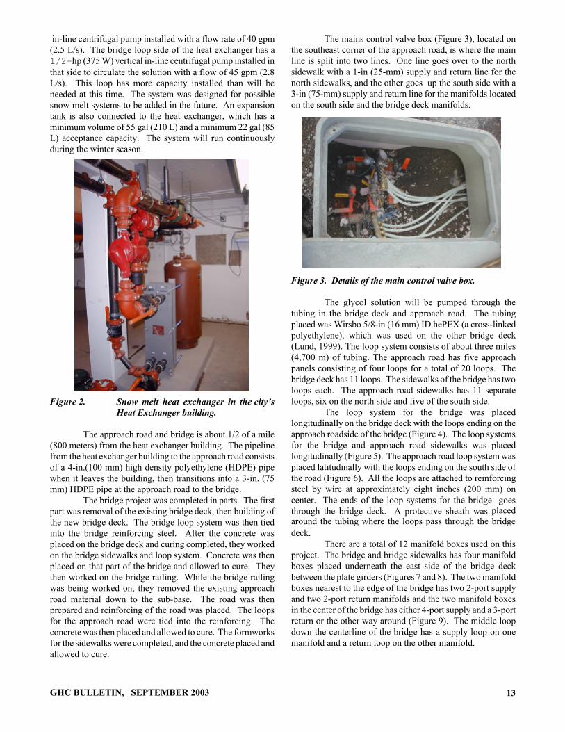
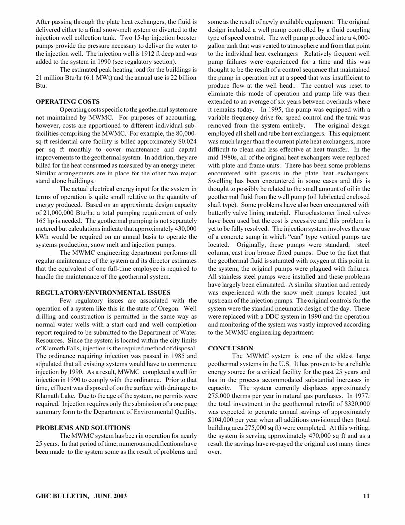
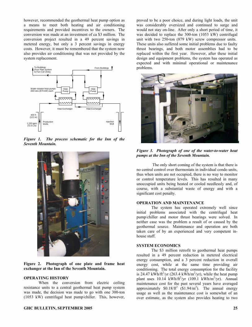
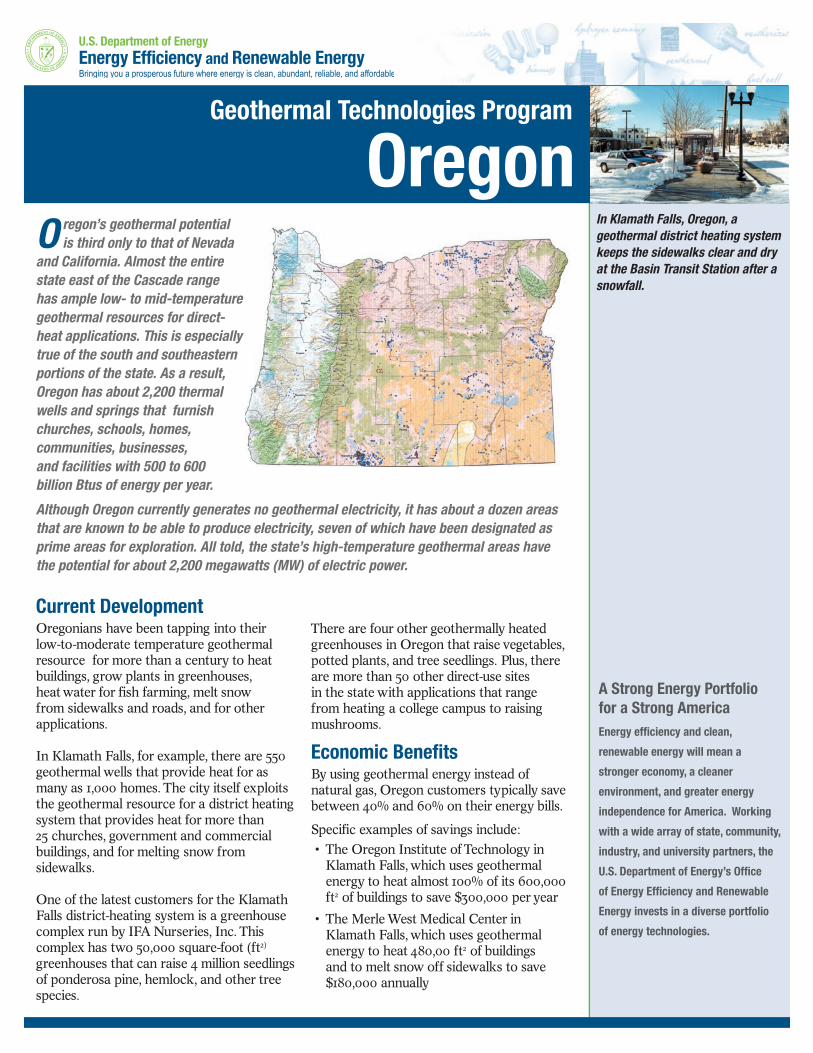
Oregon has been very blessed with geothermal. There are an estimated geothermal potential of 4,600 MWt for 30 yr (below 150oC) in Oregon, but only a little over 1.4 percent of that is being utilized. A summary of the direct-uses known by the Geo-Heat Center located in Oregon is listed below. The information below contains capacity of direct-use, temperature of the resources, any information known by the author and any webpages links know at the time of this writing for each place. Klamath Falls Oregon Institute of Technology, Klamath Falls District Heating Capacity 6.2 MWt Annual Energy Use: 13.7 GWh/yr CO2 emissions saved: 10,950 tons/yr Temperature 192oF Snow Melting Capacity 0.06MWt Annual Energy Use: 0.1 GWh/yr CO2 emissions saved: 80 tons/yr Temperature 150oF Currently serves all of the campus heating (650,000 sq ft), snow melting (2,500 sq ft). This heating system saves the campus approximately $1,000,000 in heating costs per year. The campus administration is proposing to drill a well (5,000 to 6,000 ft – 1,500 to 1,800 m) deep into a fault that is known to have a geothermal resource around 300˚F (150˚C), to generate electricity. If this is successful, a one megawatt (MWe) geothermal power plant of either a flash steam or binary type will be installed to provide all the electricity needs on campus. This will provide an additional savings of around $500,000 and reduce CO2 emissions by about 16,000 tonnes annually (compared to producing it from petroleum). The campus would then be 100% “green” by producing all of its energy needs from geothermal resources. Bulletin Articles “Chill Out” – Oregon Institute of Technology is a Winner http://geoheat.oit.edu/bulletin/bull28-2/art3.pdf The Oregon Institute of Technology Geothermal Heating System - Then and Now http://geoheat.oit.edu/bulletin/bull20-1/art3.pdf New Snow Melting Projects in Klamath Falls, OR http://geoheat.oit.edu/bulletin/bull24-3/art3.pdf City of Klamath Falls District Heating System District Heating Capacity 8.5 MWt Annual Energy Use: 18.7 GWh/yr CO2 emissions saved: 14,940 tons/yr Temperature 210oF Snow Melting Capacity 1.2 MWt Annual Energy Use: 1.0 GWh/yr CO2 emissions saved: 800 tons/yr Temperature 125oF
Greenhouse Capacity: N/A Annual Energy Use: N/A CO2 emissions saved: N/A Temperature 199oF Current serves process heating at the Klamath Falls wastewater treatment plant, 24 buildings (400,000 sq. ft.), greenhouses (150,000 sq. ft.)(IFA Greenhouses), snow melting (105,000 sq ft.). Expansion of the district heating system mains and development of a new sidewalk snowmelt system was undertaken in 2006 to serve the Timbermill Shores development on a former mill site. The greenhouse operation is on the City of Klamath Falls district heating system and included in the district heating numbers Bulletin Articles Klamath Falls Geothermal District Heating System at 25 Years http://geoheat.oit.edu/bulletin/bull28-2/art3.pdf From Creamery to Brewery with Geothermal Energy: Klamath Basin Brewing Company http://geoheat.oit.edu/bulletin/bull27-4/art1.pdf Klamath Falls Geothermal District Heating Systems http://geoheat.oit.edu/bulletin/bull20-1/art2.pdf New Snow Melting Projects in Klamath Falls, OR http://geoheat.oit.edu/bulletin/bull24-3/art3.pdf City website http://www.ci.klamath-falls.or.us/ Highway De-icing Snow Melting Capacity 0.4 MWt Annual Energy Use: 1.8 GWh/yr CO2 emissions saved: 1,440 tons/yr Temperature 190oF Bulletin article – Reconstruction of a Pavement Geothermal Deicing System http://geoheat.oit.edu/bulletin/bull20-1/art4.pdf Klamath County Vandenberg Road Complex Space Heating Capacity 3.1 MWt Annual Energy Use: 6.7 GWh/yr CO2 emissions saved: 5,350 tons/yr Temperature 151oF The complex is on a hill top about 100 ft higher than the surrounding terrain and originally was somewhat isolated but businesses and residences are being developed nearby including the new Herald and news building. It currently services about 100,000 sq ft (Klamath County Jail, County Sheriff’s Offices, Mental Health Building, Juvenile Detention and County Extension office). Case Study Klamath County Vandenberg Road Complex http://geoheat.oit.edu/bulletin/bull25-1/art2.pdf Herald and News Space Heating Capacity 0.4 MWt Annual Energy Use: 0.9 GWh/yr CO2 emissions saved: 720 tons/yr Temperature average 212oF Snow Melting Capacity 0.15 MWt Annual Energy Use: 0.3 GWh/yr CO2 emissions saved: 240 tons/yr Temperature average 212oF This building is under construction and should be operational by late 2007. Klamath Falls Residence (600) Space Heating Capacity 12.8 MWt Annual Energy Use: 28.0 GWh/yr CO2 emissions saved: 22,370 tons/yr Temperature average 185oF Approximately 550 wells are used to heat homes in the Hot Springs and surrounding area of Klamath Falls. Most use what is referred to as a downhole heat exchanger which takes heat out of the geothermal water in a closed loop without having to
pump the well. A typical residential well can provide up to about 250,000 Btu/hr (0.1 MWt) of energy, and installations with multiple DHE, such as for schools, provide about 10 times this amount of energy. Well depths in the city vary from 100 to 1,800 feet, with 300 feet being the average. Temperatures vary from 120 to 220oF, with 140oF and above considered desirable for providing sufficient energy using a DHE. Case Study Residential Downhole Heat Exchanger, Klamath Falls, Oregon http://geoheat.oit.edu/bulletin/bull25-1/art3.pdf Merle West Medical Center (MWMC) Complex (Renamed Sky Lakes Medical Center) Space Heating Capacity 6.1 MWt Annual Energy Use: 13.7 GWh/yr CO2 emissions saved: 10,950 tons/yr Temperature 195oF The original geothermal system for MWMC was designed to provide space heat and domestic hot water to the 96,000-sq ft main building; a new 56,000-sq-ft addition; the adjacent 56,000-sq ft nursing home and snow melting for the main entrance area. Since that time, the approximate areas heated have grown to include 300,000-sq-ft main building; 45,000-sq-ft medical office building; 56,000-sq-ft nursing home and a 80,000-sq-ft residential care facility (2003). The new 100,000 sq ft addition was just completed in 2007. Case Study Merle West Medical Center, Klamath Falls, OR http://geoheat.oit.edu/bulletin/bull24-2/art4.pdf REACH (originally Maywood Industries) Space Heating Capacity: 0.5 MWt Annual Energy Use: 2.4 GWh/yr CO2 emissions saved: 1920 tons/yr Temperature 118oF Currently heats a 110,000 sq. ft. building and is served by a single production well, 1520 ft deep, which had a temperature of 118oF when drilled. The well was pump tested at a flow of 320 gpm with a 115 ft drawdown. The present installed capacity is about 0.5 MWt, utilizing 8.2 billion Btu/yr at a savings of $75,000/yr (compared to natural gas). Case Study REACH, Inc. Juniper Processing Plant, Klamath Falls, Oregon http://geoheat.oit.edu/bulletin/bull25-1/art4.pdf Klamath Falls City Schools (6) Space Heating Capacity 2.6 MWt Annual Energy Use: 5.8 GWh/yr CO2 emissions saved: 4,630 tons/yr Temperature 180oF This includes 6 city schools (Klamath Union High (location of Big Springs), Mazama High School, Roosevelt Elementary Ponderosa Jr. High ((largest downhole exchanger system with a 0.88 MWt capacity), Mills Elementary and Klamath Insitute) Klamath County Maintenance Shop Space Heating Capacity 0.5 MWt Annual Energy Use: 1.1 GWh/yr CO2 emissions saved: 880 tons/yr Temperature 118oF Klamath Falls Swimming Pools (4) Resort/Spa Capacity 0.3 MWt Annual Energy Use: 1.3 GWh/yr CO2 emissions saved: 1,040 tons/yr Temperature 180oF This includes the 4 pools located in Klamath Falls (OIT pool, Ellen Redkey swimming pool, KU pool and YMCA pool). The Ella Redkey Municipal swimming pool uses a downhole heat exchanger. YMCA Space Heating Capacity 0.4 MWt Annual Energy Use: 0.9 GWh/yr CO2 emissions saved: 720 tons/yr Temperature 147oF
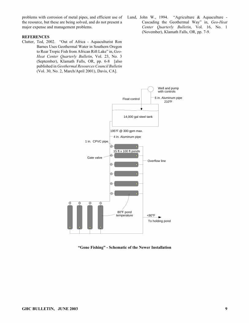
The pool heating information is included in the Klamath Falls Swimming Pools numbers YMCA website http://www.kfallsymca.org/default.asp Henley High School (Klamath County School) Space Heating Capacity 0.9 MWt Annual Energy Use: 1.9 GWh/yr CO2 emissions saved: 1,520 tons/yr Temperature 127oF Klamath Falls Apartment Buildings (13) Space Heating Capacity 0.9 MWt Annual Energy Use: 1.9 GWh/yr CO2 emissions saved: 3,360 tons/yr Temperature average 180oF Klamath Falls Churches (5) Space Heating Capacity 0.5 MWt Annual Energy Use: 1.1 GWh/yr CO2 emissions saved: 880 tons/yr Temperature 109oF Klamath Hills, Klamath County Gone Fishing Aquaculture Capacity1.2 MWt Annual Energy Use: 8.2 GWh/yr CO2 emissions saved: 6,550 tons/yr Temperature 210oF A small part of the operation is located on the Liskey Ranch . Case Study “Gone Fishing” Aquaculture Project, Klamath Falls, Oregon http://geoheat.oit.edu/bulletin/bull24-2/art3.pdf Geothermal Resources Council Bulletin article http://www.geothermal.org/articles/fish.pdf Liskey Ranch Liskey Greenhouses, Greenhouse Capacity 1.7 MWt Annual Energy Use: 4.5 GWh/yr CO2 emissions saved: 3,600 tons/yr Temperature 199oF GreenFuels of Oregon, Industrial Capacity N/A Annual Energy Use: N/A CO2 emissions saved: N/A Temperature 180oF The two operations are located on the Liskey Ranch. The Biodiesel should be operational by this summer. The equipment is in place waiting on the feedstock. Newpaper Article Persistence & innovation: Liskey family found ways to profit from geothermal water http://www.capitalpress.info/main.asp?SectionID=67&SubSectionID=792&ArticleID=31132&TM=7157.174 Bulletin Articles New Greenhouses in Klamath Falls http://geoheat.oit.edu/bulletin/bull23-3/art3.pdf GreenFuels of Oregon: Geothermal Energy utilization in Biodiesel http://geoheat.oit.edu/bulletin/bull28-1/art3.pdf Klamath County Langel Valley, Bonanza Space Heating Capacity 0.03MWt Annual Energy Use: 0.03 GWh/yr CO2 emissions saved: 24 tons/yr Temperature 147 oF
Olene Gap Space Heating Capacity 0.03 MWt Annual Energy Use: 0.03 GWh/yr CO2 emissions saved: 24 tons/yr Temperature 189oF A home is heated from a thermal spring and nearby a 450 ft well could produce 300 gpm at 224 F. About half a dozen thermal springs exist in the area. (Sammel, 1980) Lakeview Hunter’s Hot Springs Resort Space Heating Capacity 0.2 MWt Annual Energy Use: 0.5 GWh/yr CO2 emissions saved: 400 tons/yr Temperature 202oF Resort/Spa Capacity 0.3 MWt Annual Energy Use: 2.1 GWh/yr CO2 emissions saved: 1680 tons/yr Temperature 202oF "Old Perpetual" is the name to Lakeview's famous Geyser, located at Hunter's Resort just North of Lakeview. This Geyser was created by the accidental drilling of a water well. The drilling tapped into the geothermal hot water table below the surface, and ever since a Geyser of boiling water explodes nearly every minute. Hunter’s Hot Springs Resort website http://www.huntersresort.com/ Other website http://www.lakevieworegon.us/Tour/Tour9.html Warner Creek Correctional Facility Space Heating Capacity N/A Annual Energy Use: N/A CO2 emissions saved: N/A Temperature oF Oregon Department of Corrections website http://www.oregon.gov/DOC/OPS/PRISON/wccf.shtml Lakeview Residences (9) Space Heating Capacity 0.1 MWt Annual Energy Use: 0.3 GWh/yr CO2 emissions saved: 240 tons/yr Temperature 190oF Nine homes (Justus, 1979) The Greenhouse Greenhouse Capacity 1.4 MWt Annual Energy Use: 3.6 GWh/yr CO2 emissions saved: 2880 tons/yr Temperature 220oF PO Box 709, Lakeview, OR 97630 541-947-3923 Lakeview Swimming Pool Reosrt/Spa Capacity 0.2 MWt Annual Energy Use: 0.5 GWh/yr CO2 emissions saved: 400 tons/yr Temperature 180oF A public swimming pool uses geothermal for pool, Domestic Hot Water and locker room heating Ashland Jackson Wellsprings Space Heating Capacity 0.2 MWt Annual Energy Use: 1.3 GWh/yr CO2 emissions saved: 1040 tons/yr Temperature 111oF Greenhouse Capacity 0.09MWt Annual Energy Use: 0.1 GWh/yr CO2 emissions saved: 80 tons/yr Temperature 111oF
Resort/Spa Capacity 0.3 MWt Annual Energy Use: 2.1 GWh/yr CO2 emissions saved: 1680 tons/yr Temperature 111oF
Jackson Wellsprings, a 30 acre hot springs spa located 1.5 miles from the Oregon Shakespeare Festival in pastoral Ashland, Oregon specializes in mineral springs, swimming, hot water soaking and massage therapy. Eugena Jackson dedicated that the warm mineral springs arising from Jackson Hot Springs shall be utilized for the purposes of health and healing. In 1862 deeded water rights filed with Jackson County protected the springs for “sanitarium and natatorium purposes”. Today, almost 80,000 gallons of warm water are collected each day and pass into the 45 x 90 foot swimming pool and private soaking tubs. One of WellSprings’ strongest features, the mineral water is the cornerstone of the spa and hydrotherapy center. A warm water therapy pool measuring 14 x 18 feet is maintained at 97 degrees during daytime hours. Water temperatures are boosted during evening hours to 103. Our 100 x 30 foot propagation greenhouse and shade house greatly enhance WellSprings’ abilities to introduce diversity to its botanical gardens and pharmacy, alike.
Jackson Wellsprings website http://jacksonwellsprings.com/ Lithia Springs Resort Space Heating and Resort/Spa Capacity 0.2 MWt Annual Energy Use: 1.3 GWh/yr CO2 emissions saved: 1040 tons/yr Temperature 220oF Lithia Springs Resort website http://www.ashlandinn.com/index.html Vale Oregon Trail Mushrooms Industrial Capacity 1.5 MWt Annual Energy Use: 12.6 GWh/yr CO2 emissions saved: 10,070 tons/yr Temperature 220oF Vale Residences(5), Space Heating Capacity 0.09MWt Annual Energy Use: 0.2 GWh/yr CO2 emissions saved: 160 tons/yr Temperature 185oF Ag Dryers, Agricultural Drying Capacity: 0.9 MWt Annual Energy Use: 1.9 GWh/yr CO2 Emissions saved: 1,520 tons/yr Temperature: 200oF Vale Swimming Pool Resort/Spa Capacity 0.3 MWt Annual Energy Use: 2.1 GWh/yr CO2 emissions saved: 1,680 tons/yr Temperature oF Case Study Oregon Trail Mushrooms http://geoheat.oit.edu/bulletin/bull25-1/art5.pdf Vale Slaughter House Space Heating Capacity 0.09MWt Annual Energy Use: 0.2 GWh/yr CO2 emissions saved: 160 tons/yr Temperature 150oF Case Study Oregon Trail Mushrooms http://geoheat.oit.edu/bulletin/bull25-1/art5.pdf Summer Lake Summer Lake Hot Springs Space Heating Capacity 0.3 MWt Annual Energy Use: 0.7 GWh/yr CO2 emissions saved: 560 tons/yr Temperature 113oF Resort/Spa
Capacity 0.3 MWt Annual Energy Use: 2.1 GWh/yr CO2 emissions saved: 1680 tons/yr Temperature 113oF Summer Lake Hot Springs is graced by four natural hot springs. The spring that serves as the source for the swimming pool produces approximately 25 gallons of water per minute, at a temperature of 113 degrees. The other springs generate water ranging from 106 to 118 degrees, and serve the various houses and facilities on the property, including the new geothermally heated cabins. Prior to the early settlers' arrival, the undeveloped springs were known as "Medicine Springs" to the native Americans. In 1843, explorer John Fremont (the man credited with naming Summer Lake, due to the area’s banana belt climate) once commented on the water’s healing properties, praising the mineral springs as the best he'd come across. Today, this same therapeutic natural mineral water continues to flow through the original 15 by 30 foot pool, maintaining a temperature of 103 degrees. Summer Lake Hot springs website http://summerlakehotsprings.com/index.html Another website http://oregonhotsprings.immunenet.com/smmrlake.htm Summer Lake Aquaculture Aquaculture Capacity 1.2 MWt Annual Energy Use: 8.2 GWh/yr CO2 emissions saved: 6,550 tons/yr Temperature N/A Contact Desert Springs – Lyle Negus – 541-943-3192 Crane Crystal Crane Hot Springs Resort/Spa Capacity 0.3 MWt Annual Energy Use: 2.1 GWh/yr CO2 emissions saved: 1,680 tons/yr Temperature 185oF Simple. Rustic. Clean. Crystal Crane Hot Springs offers you the relaxing pleasure of a hot spring, with amenities that allow you to fully and peacefully enjoy your soak. Crystal Crane website http://www.cranehotsprings.com/ GeoGardens Inc. Greenhouse Capacity N/A MWt Annual Energy Use: N/A GWh/yr CO2 emissions saved: N/A tons/yr Temperature oF Jean Cain 59611 Hwy 78 Burns OR 97720 La Grande Hot Lake Springs Hot Lake Hotel, Space Heating and Resort/Spa Capacity 0.3 MWt Annual Energy Use: 2.1 GWh/yr CO2 emissions saved: 1,680 tons/yr Temperature 208oF The pool heating numbers are included in the space heating numbers. A thermal spring provides space heating to the Hot Lake Hotel and 1320 ft transmission line delivers heat to space heating, domestic hot water, hot tubs and a swimming pool at the RV park. (Rafferty, 1986). The springs flow at about 1,000,000 gallons of water a day. The average water temperature of the springs is 208 degrees. Hot Lake Hotel website http://hotlakesprings.lbsites.com/index.htm
Eagles Hot Lake RV, Space Heating and Resort/Spa Capacity 0.3 MWt Annual Energy Use: 0.5 GWh/yr CO2 emissions saved: 400 tons/yr Temperature 186oF Hot Lake has an interesting geological, pioneer, and medicinal history. The 2½ million gallons of hot (186º) water that flow out of the ground every day have always been a natural attraction for travelers in the Grand Ronde Valley. Seven Western Indian tribes used its "curative powers" and set it aside as a peace ground. The Hot Lake area was used for rest and healing of their sick and wounded, and as a summer rendezvous area. Hot Lake was first seen by white men on August 7, 1812. The
Wilson Price Hunt expedition was traveling from what is now Astoria, Oregon, to St. Louis, Missouri, and noticed the hot spring. Eagles Hot Lake RV website http://www.eagleshotlakerv.com/ Detroit Breitenbush Hot Springs Space Heating Capacity 0.4 MWt Annual Energy Use: 1.1 GWh/yr CO2 emissions saved: 880 tons/yr Temperature 212oF Resort/Spa Capacity 0.3 MWt Annual Energy Use: 2.1 GWh/yr CO2 emissions saved: 1680 tons/yr Temperature 212oF The abundant hot springs have long been a destination for those seeking healing, rejuvenation and community. Three Meadow Pools are lined with smooth rocks and overlook the river. The four tiled Spiral Tubs are aligned in the cardinal directions with increasing temperatures. They are adjoined by the cedar tub cold plunge. The Sauna is a whimsical cedar cabin resting atop the bubbling waters. The cabins are kept cozy year round with heat from the Earth’s waters. Breitenbush website http://breitenbush.com/ Union County Medical Hot Springs Space Heating and Resort/Spa Capacity 0.2 MWt Annual Energy Use: 0.3 GWh/yr CO2 emissions saved: 240 tons/yr Temperature 140oF A pioneer resort that featured an Olympic-sized swimming pool and a large hotel which is now closed to the public. The hot springs emerge from the ground at 140oF, and then are piped 200 yards to the 50 ft by 150 ft swimming pool, where the water is cooled to around 104oF. (Touring Washington and Oregon Hot springs, 2002) This remote hot springs resort hails from the historical era of major fashionable hot springs resorts, of which Oregon had several. After many years of closure, Medical Springs' saga is recently more hopeful. One of the original homesteading descendants has retired and returned to the family homestead at the hot springs with dreams of bringing back Medical Springs, perhaps as some type of bed and breakfast. Other website http://www.oregonphotos.com/Medical%20Springs.html Cove Cove Hot Spring Greenhouse Capacity 0.2 MWt Annual Energy Use: 0.4 GWh/yr CO2 emissions saved: 320 tons/yr Temperature 108oF Other website http://www.coveoregon.org/covewelcome.shtml Cove Swimming Pool Resort/Spa Capacity 0.3 MWt Annual Energy Use: 2.1 GWh/yr CO2 emissions saved: 1,680 tons/yr Temperature oF The springs are gathered in a well-designed, concrete pool, providing nearly perfect 86 degree water. The pool, measuring 60’ x 65’, is constantly refreshed by the flow of sweet mineral water at a rate of 110 gallons per minute. Warm Springs Pool at Forest Cove http://www.coveoregon.org/localattractions_pool.shtml
Haines Radium Hot Springs Space Heating and Resort/Spa Capacity 0.2 MWt Annual Energy Use: 1.1 GWh/yr CO2 emissions saved: 880 tons/yr Temperature 136oF Another of Oregon's early western health spa hot spring resorts, Radium has been closed to the public since 1986. Radium was originally called the Haines Hot Springs Sanitarium as dubbed by its builder, Dr. May. The structure was a 100 room, two story building that burned shortly after its completion in 1906. Rebuilt, it burnt down again 1915, and then the final original buildings succumbed to fire in 1926. Soon after, based on the success of the thermally heated pool in Cove, plans were executed to build a similar pool. This structure is still in place and can be see in the aerial photos below. The pool officially opened on July 4th, 1926. The pool ran in different capacities for 60 years, but has now been closed to the public for more than 20 years. Other website http://oregonhotsprings.immunenet.com/radium.htm Newspaper article: Historic hot springs on the auction block Published: April 26, 2007 http://www.bakercityherald.com/news/story.cfm?story_no=4909 Newspaper article: Hot Springs not for sale Published: April 27, 2007 http://www.bakercityherald.com/news/story.cfm?story_no=4913 Clackamas County Austin Hot Springs Resort/Spa Capacity 0.6 MWt Annual Energy Use: 0.30 GWh/yr CO2 emissions saved: 240 tons/yr Temperature 186oF There is a large spring across the North Fork of the Clackamas River that is almost a flash point spring (a flash point spring comes out of the ground as steam). The springs on the road side of the river are located under the rocks on the bank. The water here is very hot and is mixed in pools with the river water. Be very careful at this spring as the water temperature may change quickly. Austin Hot Springs is private property and signs used to be posted warning of the near flash point (where the water comes out of the ground as steam at 210 degrees) water temperatures. Other websites http://members.tripod.com/~rexs13/austin.htm http://www.oregonraindance.com/playit/austin.htm Bagby Hot Springs Resort/Spa Capacity 0.3 MWt Annual Energy Use: 2.1 GWh/yr CO2 emissions saved: 1,680 tons/yr Temperature 136oF At 2280 feet elevation, the hot springs is managed cooperatively by the Forest Service and a volunteer group, the Friends of Bagby. . The private tubs are 10 feet long by 2-3 feet wide cedar logs that have been hollowed out. The hot water comes out of two springs at about 136 degrees. The spring water is channeled by wooden flumes into numerous bath houses and private tubs When mixed with the cold water from nearby springs it is a very enjoyable soak. Bagby Hot Springs was "discovered" by Robert Bagby, a miner from Amity, Oregon, in 1881. The Native Americans used the springs for centuries before him. Legend has it that there were no weapons permitted in the area of the springs so that the people visiting the springs for healing could do so without conflict. Other websites http://members.tripod.com/~rexs13/bagby.htm http://oregonhotsprings.immunenet.com/bagby.htm Adams Bar M Ranch Resort/Spa Capacity 0.3 MWt Annual Energy Use: 2.1 GWh/yr CO2 emissions saved: 1,680 tons/yr Temperature oF
The natural hot springs water, which flows right out of the mountain, fills our 60 x 40 foot / 18 x 12 meter swimming pool and maintains a temperature of 86oF year round. The hot tub (which had a facelift and now sports jets and a heat pump) can get up to 105oF. For years people have come to Bingham Springs to soak in the water for the medicinal properties it is believed to contain. People enjoy the peace and tranquility of a late evening dip under the stars or soak in the hot tub filled with mineral water from the spring. Bar M Ranch website http://www.barmranch.com/index.php?page=1 McKenzie Bridge Belknap Hot Springs Resort/Spa Capacity 0.3 MWt Annual Energy Use: 1.6 GWh/yr CO2 emissions saved: 1,280 tons/yr Temperature 160oF A well know commercial resort on the banks of the McKenzie River. Belknap website http://www.belknaphotsprings.com/ Prairie City Blue Mountain Hot Spring Resort/Spa Capacity 0.3 MWt Annual Energy Use: 2.1 GWh/yr CO2 emissions saved: 1,680 tons/yr Temperature 120oF A hot spring with a vibrant past, Blue Mountain has had frequent visitors over the years and remains a settled destination at present. At its source the springs are 120º F but as they flow into the swimming pool they cool to about a 100 degree average. Warmer spots are closer to the piped in source, while the pool gets cooler towards the far end. The springs have been frequented as far as history is recorded for the area. The first documented settlement of the springs were by a furniture maker and his wife in the 1860s. As the decades past the springs became known as a destination for viewing the mystery of geothermal activity, those seeking wellness from the mineral rich water, drinking, swimming, and bathing. At one time under private ownership, today the hot springs are a scenic destination open to outside guests. Other website http://oregonhotsprings.immunenet.com/bluemtn.htm Canyon City J Bar L Guest Ranch Resort/Spa Capacity 0.3 MWt Annual Energy Use: 2.1 GWh/yr CO2 emissions saved: 1,680 tons/yr Temperature oF Warm Springs Kah-nee-ta Resort/Spa Capacity 2.0 MWt Annual Energy Use: 8.8 GWh/yr CO2 emissions saved: 7,030 tons/yr Temperature 128oF Case Study Kah-Nee-Ta Swimming Pool, Warm Springs, Oregon http://geoheat.oit.edu/bulletin/bull25-1/art1.pdf Kah-Nee-Ta website http://www.kahneeta.com/ Ukiah Lehman Hot Springs
Resort/Spa Capacity 0.3 MWt Annual Energy Use: 2.1 GWh/yr CO2 emissions saved: 1,680 tons/yr Temperature 167oF
Located west of La Grande, Lehman Hot Springs is one of the largest hot springs in the Northwest. The springs were formerly a gathering place for the Nez Perce Indians. The 9,000 foot square swimming pool has temperatures ranging from 88 to 106 degrees F. Relax in the soothing hot pools, or take an invigorating swim in the large pool.
Lehman Hot Springs website http://www.lehmanhotsprings.com/ Ritter Ritter Hot Springs Resort/Spa Capacity 0.3 MWt Annual Energy Use: 2.1 GWh/yr CO2 emissions saved: 1,680 tons/yr Temperature 106oF A historic overnight stop on the old stagecoach road between Pendleton and John Day. The hot springs emerge from the ground at 106oF. The hot water is piped across the Middle Fork of the John Day River to the swimming pool, which averages 85oF. The total CO2 emissions savings for the State of Oregon totals to approximately 151,198 tons/yr. Reference for CO2 are Goddard and Goddard, GRC Transactions, Vol. 14, Part I (1990), p. 649.
GEO-HEAT CENTER Oregon Institute of Technology Klamath Falls, Oregon 97601 541/885-1750 FAX 541/885-1754 John W. Lund, Director Tonya “Toni” Boyd Andrew Chiasson
Possible Oregon Geothermal Power Plant Sites
Compiled by Toni Boyd December 2006
Assumptions The smallest United Technologies Company power plant units are 200 kWe in size. The smallest ORMAT binary systems are 1 MWe in size. These numbers will be used to make recommendations. Some other assumptions used are (From a spreadsheet by Dan Hand, Chevron): Cost of Electricity $0.06 / kWh Rejection Temperature 80oF (27oC) Turbine Isentropic Efficiency – 85 % Temperature Differential – 20oF (11oC) Operational hours (95% on line) – 8322 Power Plant cost per kW - $4,000
Drilling cost - $100/ft (low side) ($300/m) Oregon Department of Energy – ODOE Oregon Energy Tax Credit – assumed 25% of cost
The numbers used for the assumptions of power plant job full time positions, person* yrs construction and manufacturing jobs and the 30 year economic output were taken from the following publication “A Handbook on the Externalities, Employment, and Economics of Geothermal Energy” by Alyssa Kagel, GEA (October 2006). The employment numbers in this report are for much larger plants (50 MWe) and should probably be only half that stated below. Other publications used were “Assessment of Geothermal Resources of the Untied States – 1978, Geological Survey Circular 790” and Western Governor’s Association Clean and Diversified Energy Initiative – Geothermal Task Force Report, Jan 2006. Below are only recommendations and assumptions for there are a lot of variables that could change the amount of power that could be produced. For example the temperature of the cooling water and the amount of flow available would affect the amount of power that could be produced at any of these sites. The smaller the temperature difference between the geothermal water and the cooling water the less power the system can produce. Part of the information below is summarized in the Spreadsheet power-summary.xls Recommendations Places listed in Table 6 of Circ 790 (90 – 150oC) Mt Hood Area This area includes Government Camp (estimated population of 735) which has three wells located within 8 km (5 miles) of the community. According to the Circ 790 it has a potential of 21.7 MWe. The highest temperature is 121oC (250oF) and the lowest is 80oC (176oF). The deepest well at 1837 m (6026 ft) is also the hottest. The other two wells are about 1220 m (4000 ft). It looks like the wells listed were exploration wells and I am not sure if they are usable. There are no flows listed either.
For the assumption of possible power generation if we assume the lower temperature well (80oC)(176oF) is usable and has a flow of 2,271 L/min (600 gpm) it could produce about 226 kWe. The cost would be approximately $903,000 if no wells have to be drilled. With a possible $226,000 possible incentive from ODOE for the BETC the net investment would be approximately $677,000. If they have to drill a well (assumed depth of 1220 m (4000 ft)) the cost would be $1,300,000, $326,000 and $977,000 respectively. This would produce one power plant job full time position and four person* yrs construction and manufacturing jobs. The 30 year economic output would be approximately $3.4 million. The water after being used in the power plant will have a temperature of 69oC (157oF) which could hot enough for direct uses like snow melting, space heating, greenhouse aquaculture and other uses. Carey (Austin) Hot Springs There are two wells and one spring in this area, which is located in the Mt. Hood National Forest. There is no communities located close for the use of the geothermal water as a cascaded use after going through the power plant, which will make the cost effectiveness of the power plant null. The ranges of temperature are 82 – 86oC (180 – 187oF) with depths of 460 and 293 meters (140 and 89 m). These wells look like they were exploration or gradient holes and I am not sure if they are usable. The spring has a listed flow of 1000 L/min (264 gpm) which would generate about 100 kWe. As mentioned in the beginning the smallest plant available is 200 kWe. If we assume using a well with a temperature of 84oC (183oF) and a flow 1893 L/min (500 gpm) it could produce about 200 kWe. The cost would be approximately $799,000 if no wells have to be drilled. With a possible $200,000 incentive from ODOE for the BETC the net investment would be approximately $600,000. If they have to drill a well (assumed depth of 375 m (1230 ft)) the cost would be $922,000, $230,000 and $692,000 respectively. This would produce one power plant job full time position and three person* yrs construction and manufacturing jobs. The 30 year economic output would be approximately $3.0 million. Last I heard Austin Hot Springs was for sale. Breitenbush Hot Springs There are five wells and one spring listed. There is a wide range of temperatures from 78 to 141oC (172 to 286oF) and the depths very from 150 to 2457 meters (46 to 749 ft). The two hottest wells are also the deepest and shallowest. They are located within the Breitenbush area and five miles from Idana with a population of 289. The information below was taken from the Breitenbush website http://www.breitenbush.com
Breitenbush Retreat and Conference Center is a worker-owned cooperative with workers and their families living as an intentional community and eco-village on 154 acres of wildlife sanctuary in the Willamette National Forest.
After looking over the Breitenbush website especially their sustainability page and I doubt they would be interested in geothermal power. I would assume the Idana community would be interested though. If we can assume Idana could use the spring which has a temperature of 92oC (198oF) and a flow of 3400 L/min (898 gpm) it could produce 399 kWe. The cost would be $1,595,000 with a possible incentive from ODOE for the BETC of $399,000 for a net investment of $1,196,000. If they have to drill a well (assumed depth of 1640 ft (500 m)) the cost would increase to $1,759,000 with a $440,000 possible tax credit and a net investment of $1,319,000. This would produce two power plant job full time position and six person* yrs construction and manufacturing jobs. The 30 year economic output would be approximately $6.0 million. Kahneetah Hot springs There is one spring at a temperature of 83oC (181oF); everything also is below 70oC (158oF). I have heard the Warm Springs Indians are looking into the feasibility of exploration for geothermal power generation among other renewables, but it looks like the geothermal is later into the future. Dave McClain would be the person to contact for information on the project. With the existing information I would not consider Kahneetah as a possible site at this time, since there is no evidence of
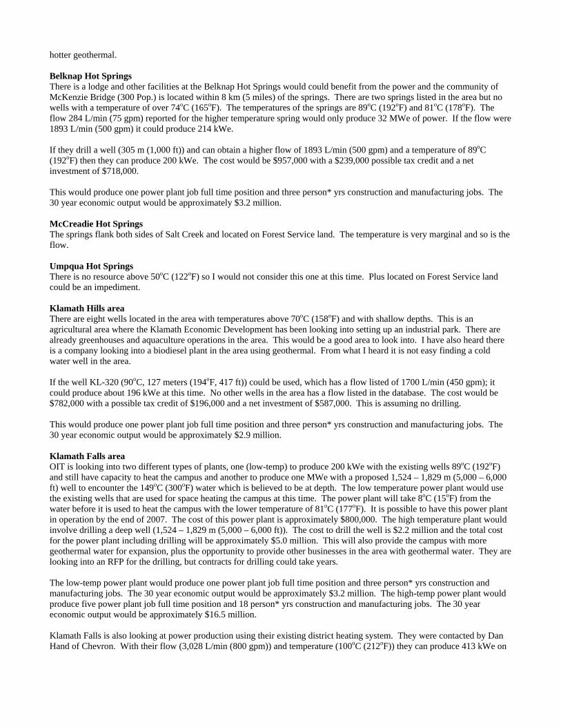
hotter geothermal. Belknap Hot Springs There is a lodge and other facilities at the Belknap Hot Springs would could benefit from the power and the community of McKenzie Bridge (300 Pop.) is located within 8 km (5 miles) of the springs. There are two springs listed in the area but no wells with a temperature of over 74oC (165oF). The temperatures of the springs are 89oC (192oF) and 81oC (178oF). The flow 284 L/min (75 gpm) reported for the higher temperature spring would only produce 32 MWe of power. If the flow were 1893 L/min (500 gpm) it could produce 214 kWe. If they drill a well (305 m (1,000 ft)) and can obtain a higher flow of 1893 L/min (500 gpm) and a temperature of 89oC (192oF) then they can produce 200 kWe. The cost would be $957,000 with a $239,000 possible tax credit and a net investment of $718,000. This would produce one power plant job full time position and three person* yrs construction and manufacturing jobs. The 30 year economic output would be approximately $3.2 million. McCreadie Hot Springs The springs flank both sides of Salt Creek and located on Forest Service land. The temperature is very marginal and so is the flow. Umpqua Hot Springs There is no resource above 50oC (122oF) so I would not consider this one at this time. Plus located on Forest Service land could be an impediment. Klamath Hills area There are eight wells located in the area with temperatures above 70oC (158oF) and with shallow depths. This is an agricultural area where the Klamath Economic Development has been looking into setting up an industrial park. There are already greenhouses and aquaculture operations in the area. This would be a good area to look into. I have also heard there is a company looking into a biodiesel plant in the area using geothermal. From what I heard it is not easy finding a cold water well in the area. If the well KL-320 (90oC, 127 meters (194oF, 417 ft)) could be used, which has a flow listed of 1700 L/min (450 gpm); it could produce about 196 kWe at this time. No other wells in the area has a flow listed in the database. The cost would be $782,000 with a possible tax credit of $196,000 and a net investment of $587,000. This is assuming no drilling. This would produce one power plant job full time position and three person* yrs construction and manufacturing jobs. The 30 year economic output would be approximately $2.9 million. Klamath Falls area OIT is looking into two different types of plants, one (low-temp) to produce 200 kWe with the existing wells 89oC (192oF) and still have capacity to heat the campus and another to produce one MWe with a proposed 1,524 – 1,829 m (5,000 – 6,000 ft) well to encounter the 149oC (300oF) water which is believed to be at depth. The low temperature power plant would use the existing wells that are used for space heating the campus at this time. The power plant will take 8oC (15oF) from the water before it is used to heat the campus with the lower temperature of 81oC (177oF). It is possible to have this power plant in operation by the end of 2007. The cost of this power plant is approximately $800,000. The high temperature plant would involve drilling a deep well (1,524 – 1,829 m (5,000 – 6,000 ft)). The cost to drill the well is $2.2 million and the total cost for the power plant including drilling will be approximately $5.0 million. This will also provide the campus with more geothermal water for expansion, plus the opportunity to provide other businesses in the area with geothermal water. They are looking into an RFP for the drilling, but contracts for drilling could take years. The low-temp power plant would produce one power plant job full time position and three person* yrs construction and manufacturing jobs. The 30 year economic output would be approximately $3.2 million. The high-temp power plant would produce five power plant job full time position and 18 person* yrs construction and manufacturing jobs. The 30 year economic output would be approximately $16.5 million. Klamath Falls is also looking at power production using their existing district heating system. They were contacted by Dan Hand of Chevron. With their flow (3,028 L/min (800 gpm)) and temperature (100oC (212oF)) they can produce 413 kWe on
their existing system and still have capacity for the district heating with not much expansion possible in the future. The cost would be $1,652,000 with a possible tax credit of $413,000 and a net investment of $1,239,000. If they drill a 305 m (1,000 ft) well to supplement the existing district heating system and power plant the cost would increase to $1,752,000 with a possible tax credit of $438,000 and a net investment of $1,314,000. This would produce two power plant job full time position and seven person* yrs construction and manufacturing jobs. The 30 year economic output would be approximately $6.2 million. Most of the other high temperature wells are located in a residential area where it would be hard to set up a power plant. The wells located in the commercial district of the town are not sufficient to produce power. Summer Lake Hot Springs This area is located within proximately of Paisley there are five wells over 70oC (158oF) with depths ranging from 126 m (413 ft) to 300 m (985 ft). All the wells listed have the same name associated with them and I would assume they are located on a ranch in the area since the latitudes and longitudes of the wells are close. There are no flows listed but if we assume a flow rate of 1500 L/min (396 gpm) for the high temperature well of 111oC (232oF) it can produce 200 kWe. The cost would be $863,000 with a possible tax credit of $216,000 and a net investment of $647,000. This would produce one power plant job full time position and three person* yrs construction and manufacturing jobs. The 30 year economic output would be approximately $3.2 million. Lakeview area This area has 25 wells and four springs listed with a temperature of 70oC (158oF) and above. The highest temperature well is also the deepest. I would assume this was an exploration well. The depth is 1658 m (5,440 ft) with a 116oC (241oF) temperature. Since there is no flow listed for this well I did not use this one in my assumptions. There is a 101oC (214oF) well with a flow 0f 3750 L/min (990 gpm) and a depth of 209 m (686 ft) and a spring with a temperature of 96oC (205oF) and 2000 L/min (528 gpm) which I will use for assumptions. At this time I am not sure if the well is located within the city limits, the spring is located at Hunter Hot Springs. The 101oC (214oF) well using all of the flow could produce 488 kWe. The cost would be $1,951,000 with a possible tax credit of $488,000 and a net investment of $1,463,000. This would produce two power plant job full time position and eight person* yrs construction and manufacturing jobs. The 30 year economic output would be approximately $7.3 million. The spring located at Hunter Hot Springs could produce 246 kWe. I would assume the owner might be interested in the power generation as long as he is able to still use it for his other applications like space heating and pool heating. Not sure if he has the capacity to do both. The cost would be $983,000 with a possible tax credit of $246,000 for a net investment of $738,000. This would produce one power plant job full time position and four person* yrs construction and manufacturing jobs. The 30 year economic output would be approximately $3.7 million. Fisher and Weberg Hot Springs There are no wells and springs listed over 70oC therefore I would not suggest either site at this time. Harney Lake Area The temperatures of the wells in this area are just below the temperature of the Chena Hot Springs well and I would not recommend this site at this time. Crane Hot springs This area contains a resort and down the road to the west there is a greenhouse operation. The temperatures are at 78o and 82oC (162o and 180oF) and the depth of the well is 76 m (249 ft). Using the following 82oC and 700 L/min (185 gpm) of flow it can only produce about 72 kWe and as I mentioned earlier the smallest available plant is 200 kWe plant. The owners of Crystal Hot Springs might be interested is a geothermal plant. If a well is drilled (305 m (1,000 ft)) in the area of Crystal Crane Hot Springs and they could encounter the same temperature and a flow of 2,082 L/min (550 gpm) they could produce 214 kWe. The cost would be $857,000 with a possible tax credit incentive of $214,000 for a net investment of $643,000.
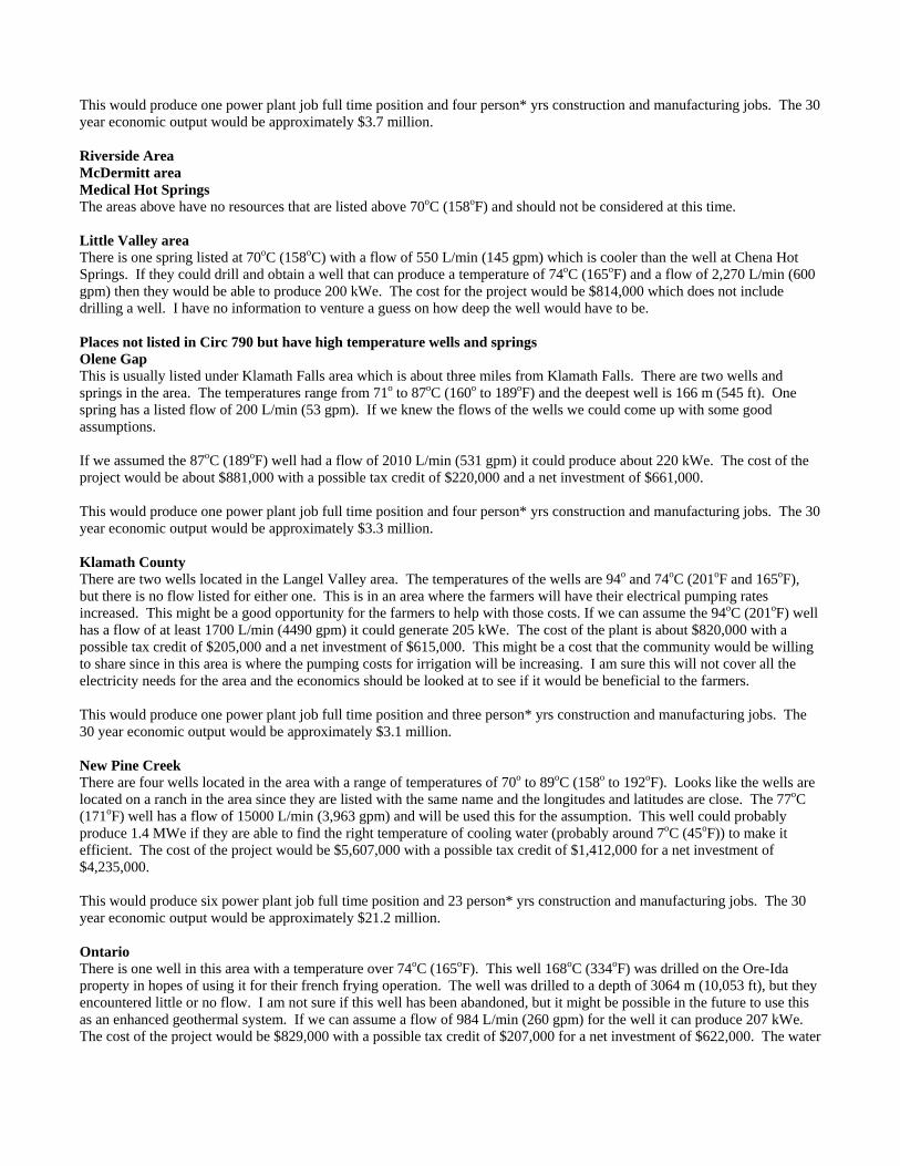
This would produce one power plant job full time position and four person* yrs construction and manufacturing jobs. The 30 year economic output would be approximately $3.7 million. Riverside Area McDermitt area Medical Hot Springs The areas above have no resources that are listed above 70oC (158oF) and should not be considered at this time. Little Valley area There is one spring listed at 70oC (158oC) with a flow of 550 L/min (145 gpm) which is cooler than the well at Chena Hot Springs. If they could drill and obtain a well that can produce a temperature of 74oC (165oF) and a flow of 2,270 L/min (600 gpm) then they would be able to produce 200 kWe. The cost for the project would be $814,000 which does not include drilling a well. I have no information to venture a guess on how deep the well would have to be. Places not listed in Circ 790 but have high temperature wells and springs Olene Gap This is usually listed under Klamath Falls area which is about three miles from Klamath Falls. There are two wells and springs in the area. The temperatures range from 71o to 87oC (160o to 189oF) and the deepest well is 166 m (545 ft). One spring has a listed flow of 200 L/min (53 gpm). If we knew the flows of the wells we could come up with some good assumptions. If we assumed the 87oC (189oF) well had a flow of 2010 L/min (531 gpm) it could produce about 220 kWe. The cost of the project would be about $881,000 with a possible tax credit of $220,000 and a net investment of $661,000. This would produce one power plant job full time position and four person* yrs construction and manufacturing jobs. The 30 year economic output would be approximately $3.3 million. Klamath County There are two wells located in the Langel Valley area. The temperatures of the wells are 94o and 74oC (201oF and 165oF), but there is no flow listed for either one. This is in an area where the farmers will have their electrical pumping rates increased. This might be a good opportunity for the farmers to help with those costs. If we can assume the 94oC (201oF) well has a flow of at least 1700 L/min (4490 gpm) it could generate 205 kWe. The cost of the plant is about $820,000 with a possible tax credit of $205,000 and a net investment of $615,000. This might be a cost that the community would be willing to share since in this area is where the pumping costs for irrigation will be increasing. I am sure this will not cover all the electricity needs for the area and the economics should be looked at to see if it would be beneficial to the farmers. This would produce one power plant job full time position and three person* yrs construction and manufacturing jobs. The 30 year economic output would be approximately $3.1 million. New Pine Creek There are four wells located in the area with a range of temperatures of 70o to 89oC (158o to 192oF). Looks like the wells are located on a ranch in the area since they are listed with the same name and the longitudes and latitudes are close. The 77oC (171oF) well has a flow of 15000 L/min (3,963 gpm) and will be used this for the assumption. This well could probably produce 1.4 MWe if they are able to find the right temperature of cooling water (probably around 7oC (45oF)) to make it efficient. The cost of the project would be $5,607,000 with a possible tax credit of $1,412,000 for a net investment of $4,235,000. This would produce six power plant job full time position and 23 person* yrs construction and manufacturing jobs. The 30 year economic output would be approximately $21.2 million. Ontario There is one well in this area with a temperature over 74oC (165oF). This well 168oC (334oF) was drilled on the Ore-Ida property in hopes of using it for their french frying operation. The well was drilled to a depth of 3064 m (10,053 ft), but they encountered little or no flow. I am not sure if this well has been abandoned, but it might be possible in the future to use this as an enhanced geothermal system. If we can assume a flow of 984 L/min (260 gpm) for the well it can produce 207 kWe. The cost of the project would be $829,000 with a possible tax credit of $207,000 for a net investment of $622,000. The water
after going through the power plant could probably then be used in the Ore-Ida plant. Even if they take out 56oC (100oF) out of the water it could still have a temperature of 106oC (224oF) which can be used in an industrial process. This would produce one power plant job full time position and three person* yrs construction and manufacturing jobs. The 30 year economic output would be approximately $3.1 million. Nyssa There is one well located in the area with a temperature of 84oC (183oF) with depth of 478 m (1568 ft), but no flow listed. This was an exploration well. If we assume the well has a flow of 2082 L/min (550 gpm) then it can produce 220 kWe. The cost would be $879,000 with a possible $220,000 tax credit and a net investment of $659,000. This would produce one power plant job full time position and four person* yrs construction and manufacturing jobs. The 30 year economic output would be approximately $3.3 million. Adrain This area has two wells and spring listed in the area with temperatures ranging from 71o to 79oC (160o to 174oF). The depths of the wells are listed at 8 and 18 m (26 and 59 ft), but again no flows are listed. The spring has the highest temperature and if we assume a flow of 2082 L/min (550 gpm) it could produce 203 kWe. The cost of the project would be $813,000 with a possible incentive of $203,000 and a net investment of $610,000. This looks like there might be some hotter temperatures at depth, but I have not heard much mention of this area. This area might be worth looking into. This would produce one power plant job full time position and three person* yrs construction and manufacturing jobs. The 30 year economic output would be approximately $3.0 million. Marion County This well is located in Marion County at 44.852 and 121.832. This could have been an exploration well, but can not be sure. It has a temperature of 87oC (189oF) with a depth of 1465 m (4,905 ft). If we assume the well has a flow of 1893 L/min (500 gpm) it can produce 208 kWe. The cost of the project would be approximately $831,000 with a possible tax credit of $208,000 and a net investment of $623,000. This would produce one power plant job full time position and three person* yrs construction and manufacturing jobs. The 30 year economic output would be approximately $3.1 million. Union This area has two wells and two springs in the area. One of them is listed as Hot Lake Springs. It has a temperature listed at 85oC (185oF) and a flow of 5,700 L/min (1,506 gpm). This could probably produce 609 kWe. The cost of the project would be approximately $2,435,000 with a possible tax credit of $609,000 and a net investment of $1,827,000. I am not sure if the resource is being used at this time, but it will still have quite a bit of beneficial heat after going through the power plant to be used for other applications of direct use. This would produce three power plant job full time position and 10 person* yrs construction and manufacturing jobs. The 30 year economic output would be approximately $9.1 million. Table 5 from Circ 790 (above 150oC (302oF)) Newberry Caldera The area is currently being explored and development for power generation. This project is being developed on federal leases. Since this is being actively explored I did not include this in the assumptions. The information below was taken from Davenport Power’s website
Davenport Power, LLC is the Project Operator and a co-owner of this geothermal field. The company controls 50% of Northwest Geothermal Company (NGC), a joint venture formed to develop the Newbery project on a 14,000 acre lease position. The Newberry geothermal leases have been extensively drilled and explored. The field is potentially large, based on hot temperature gradient holes and a superheated steam well, with hundreds of megawatts of geothermal power potential. Newberry Volcano is considered one of the premier geothermal fields in the world.
Davenport Power on behalf of the Northwest Geothermal Company signed a 20-year power sales agreement with Pacific Gas & Electric Company, a major west coast utility, in July 2006. The agreement involves selling between 60 and 120 MWe of electricity from a proposed geothermal power project on the western side of the Newberry Volcano in central Oregon. Drilling preparation and environmental work will begin in 2006 and the first 30 MWe of the project is scheduled to achieve operating status in late 2009. The second 30 MWe is scheduled to begin operating in 2010 and provided that expected resource and transmission service are available, the remaining 60 MWe of the project is scheduled for 2011.
The Western Governor’s Geothermal Task Report says that Newberry has a potential of having 240 MWe online by 2010 with a near market cost of $0.08 / kWh. If Davenport Power can get the 120 MWe power plant operation it could produce 510 power plant job full time position and 1920 person* yrs construction and manufacturing jobs. The 30 year economic output would be approximately $1.8 billion. Crump Hot Springs This area is currently being explored for power generation. This project is being developed on private leases. Since this is being actively explored I did not include this in the assumptions. The information below was taken from Nevada Geothermal Power’s website
May 2006, an independent review by GeothermEx, Inc. of Richmond, California provide a preliminary estimate of capacity at Crump Geyser, a minimum of 40 MWe and most likely 60 MWe. A corporate review of the exploration results to date and the positive analysis by GeothermEx, Inc., NGP intends to advance the Crump Geyser project through reservoir drilling, testing and confirmation and project feasibility studies.
They are looking into placing 40 MWe online by 2008. The Western Governor’s Geothermal Task Report says that Crump Geyser has a potential of having 20 MW online by 2010 with a near market cost of $0.08 / kWh. If Nevada Geothermal Power can get the 40 MWe power plant operation it could produce 170 power plant job full time position and 640 person* yrs construction and manufacturing jobs. The 30 year economic output would be approximately $599 million. Mickey’s Hot Springs This area only has some springs with temperatures listed at 73oC (163oF). Listed as having a potential in Circ 790 (160 MWe) and in the Western Governors Geothermal Task Report (Near Term (25 MWe)), but with out extensive exploration to look into the resource I would not recommend this site at this time. Alvord Hot Springs This area is listing in Circ 790 but not as a potential site in the Western Governors Geothermal Task Report. One reason it was not considered is due to the chub fish located in the lake. It is considered an endangered species I think and there has been controversy over it that if they develop a power plant in the area it will affect the lake where the fish is located. There is one spring located in the area which I assume empties into the lake with a temperature of 78oC (172oF) and a flow of 1875 L/min (495 gpm). This spring could produce 180 kWe. The cost of the project would be approximately $719,000 with a possible tax credit of $180,000 and a net investment of $539,000. This would produce three power plant job full time position and 10 person* yrs construction and manufacturing jobs. The 30 year economic output would be approximately $9.1 million. Hot (Borax) Lake Area This area only has a couple of springs listed with temperatures of 97o and 91oC (207oF and 196oF). The flow for each is listed as 10 L/min (2.6 gpm). Circ 790 lists this as having a potential of 91 MWe, and the Western Governor’s Task Report has included this with the Lakeview area and both have a potential of 20 MWe. Without extensive exploration to look at the resource I would not recommend this site at this time. Trout Creek Area This area does not have a resource with a temperature over 70oC (158oF). Both the Circ 790 (24 MWe) and Western
Governor’s Task Report (10 MWe) this area has a potential for power generation. Without extensive exploration to look at the resource I would not recommend this site at this time. Neal Hot Springs This area has been acquired by US Geothermal Inc. The company is currently developing a power plant project at Raft River in Idaho. Neal Hot Springs (8.5 square mile property) was acquired from a private party. Since this is being actively explored I did not include this in the assumptions. The information below was taken from their website.
“We are pleased to have acquired this important geothermal resource, and we’re working to advance the project to a development decision and have targeted an initial production potential of 25-30 MWe,” said David Kunz, U.S. Geothermal CEO, who emphasized that the Oregon site is close to transmission lines and a “great location” to serve Idaho Power’s growing utility base as well as the broader Pacific Northwest energy market.
If US Geothermal Power can get the 25 MW power plant operation it could produce 106 power plant job full time position and 400 person* yrs construction and manufacturing jobs. The 30 year economic output would be approximately $375 million. Vale Hot Springs This area has 30 wells and one spring which are located in town. The geothermal water is used for several direct use applications like refrigeration for mushroom growing, dry of corn and space heating. The highest temperature listed in the database is 115oC (239oF). The deepest well is 265 m (869 ft). The database does not include the exploration well that was drilled south of town. This well encountered a high temperature but encounter little or no flow. The wells located in town have encountered some water level drops in recent years. This would have to be taken into consideration if a power plant was to be developed in this area. If we use the 115oC (239oF) well (MA-104) which has a flow of 1325 L/min (350 gpm) listed and the well (MA-105) with a temperature of 108oC (226oF) and a flow of 1514 L/min (400 gpm) for assumptions of potential power. The MA-104 well could produce 198 kWe and the cost of the project would be approximately $794,000 with a possible tax credit of $198,000 for a net investment of $596,000. The MA-105 well could produce 212 kWe and the cost for the project would be $849,000 with a possible tax credit of $212,000 and a net investment of $637,000. The MA-104 well would produce one power plant job full time position and three person* yrs construction and manufacturing jobs. The 30 year economic output would be approximately $2.9 million. The MA-105 well would produce one power plant job full time position and three person* yrs construction and manufacturing jobs. The 30 year economic output would be approximately $3.2 million.
ADRIAN
ADEL
BEULAH
BONANZA
BURNS
CRANE
FIELDS
GOVERNMENTCAMP
JEFFERSON
KEHNEETA
KLAMATHFALLS
LORELLA
McCREDIESPRINGS
HAINES
HARNEY
BREITENBUSH
LAWEN
LAKEVIEW
LEHMANSPRINGS
McKENZIE
NEW PINE CREEK
NYSSA
ONTARIO
PAISLEY
PONDOSA
POWELL BUTTE
RIVERSIDE
SILVERTON
UNION
VALE
SUMPTER
HARPER
Temp,oC / Depth, m Flow, L/min / TDS, mg/L
LEGEND
121o / 1426416 /
72o / 2379 /
89o / 3103408 /
56o / /
58o / 1498 /
89o / 130395 / 57o / 461
/
73o / 75 /
61o / /
85o / 6155 /
61o / 200 /
57o / 37.51150 /
57o / 105 /
60o / 50 /
115o / 812914 /
70o / 125550 /
84o / 478 /
79o / 41060 /
63o / 225 /
72o / 287 1000 /
71o / 696 /
57o / 55935 /
82o / 50 700 /
97o / 20 / 89o / 170
5000 / 113o / 1846539 /
111o / 210 75 /
121o / 196 60 /
61o / 150 /
105o / 200 8377 / 902
94o / 70 /
HOT SPRING
Oregon Communitieswith Geothermal Resource
Development Potential
The cities and towns of Oregon shown on this map are locatedwithin 8 km (5 miles) of a known geothermal resource
that has a temperature greater than 50oC (122oF)
GEO-HEAT CENTER Oregon Institute of Technology Klamath Falls, Oregon 97601 541/885-1750 FAX 541/885-1754 John W. Lund, Director Tonya “Toni” Boyd
Oregon Collocated Communities
Compiled by Toni Boyd
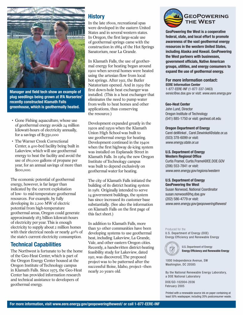
January 2008 A 1994 Oregon Department of Geology and Mineral Industries (DOGAMI) report entitled “Low-Temperature Geothermal Database for Oregon” by G. Black compiled a database of thermal wells and springs. These thermal wells and springs may represent more than 200 resources areas. The study concluded that the entire state east of the Cascade Range, except for the crest of the Wallowa Mountains, was favorable for the discovery at shallow depth (<3000 ft (<1000 m)) for thermal water sufficient temperature for direct-use applications. The above mentioned database was further searched and compiled to include only those wells and springs with a temperature of 122oF (50oC) and above and located within 5 miles (8 km) of a community. The purpose of this compilation was to identify and encourage those communities to develop their geothermal resources. Historically, most of the communities that were identified have experienced some development of their geothermal resources. However, depending on the characteristics of the resource, the potential exists for increased geothermal development for applications such as space- and district heating industrial, greenhouse and aquaculture operations, resort/spa facilities and possible electric power generation in some areas. There were 32 communities identified in Oregon and with a temperature at or above of 122oF (50oC). The communities are listed below by county and the information included for each community is temperature, depth, flow, number of wells and/or springs and what potential applications could be utilized at the given temperature. Baker County Haines Temp 134oF Depth 125 ft Flow listed at 304 gpm 2 wells one spring With this temperature there is a possibility of greenhouse and aquaculture operation, resort/spa facility and maybe space heating. Sumpter / Bourne Temp 134oF Depth 345 ft No flow listed 1 well With this temperature there is a possibility of greenhouse and aquaculture operation, resort/spa facility and maybe space heating. Clackamas County Government Camp Temp 250oF Depth 4678 ft
Flow 110 gpm 3 wells These were originally exploration wells and not sure if they are usable. Have to go deep for the temperature. The city is at the feasibility of developing a district heating system. Other possibilities are industrial, space heating, greenhouses and aquaculture operations and resort/spa facilities. There are two hot springs located in Clackamas which are Austin (186 F) and Bagby Hot Springs (136 F). We have been contacted by somebody interested in developing the Austin hot springs, but have not heard from them lately. Crook County Powell Butte Temp 135oF Depth 1512 ft No flow listed 1 well I think this was also another exploration well. With this temperature there is a possibility of greenhouse and aquaculture operation, resort/spa facility and maybe space heating. There are no developments around this area. Harney County Burns Temp 160oF Depth 2283 ft No flow listed 2 wells With this temperature there is a possibility of greenhouse and aquaculture operation, resort/spa facility and maybe space heating. According to database there are only two wells listed above 122oF. We do know there is a well located at the RV manufacturer place in Burns which uses the geothermal. I do not know of any other operations at this time in Burns. Crane Temp 180oF Depth 164 ft Flow 185 gpm 2 well and 1 spring With this temperature there is a possibility of greenhouse and aquaculture operation, resort/spa facility and maybe space heating, but would be marginal for industrial applications. According to the database there are only 2 wells and one spring, I know of several others in the area at the greenhouse in Crane. I have also heard that a lot of the irrigation wells in the area are also warm. There is a greenhouse operation and a hot springs resort located within 2 miles of each other Fields Temp 206oF Depth Flow 5 gpm 3 springs With this temperature there is a possibility of greenhouse and aquaculture operation, resort/spa facility, space heating and industrial applications. We have no listing of geothermal being used in the area. Harney Temp 161oF Depth 941 ft Flow 264 gpm 2 wells With this temperature there is a possibility of greenhouse and aquaculture operation, resort/spa facility and maybe space heating. We have no listed of geothermal being used in the area. Lawen Temp 136oF Depth 1834 ft Flow 9 gpm
2 wells With this temperature there is a possibility of greenhouse and aquaculture operation, resort/spa facility and maybe space heating. Lawen is located between Burns and Crane but have not geothermal use activity listed in the area. Klamath County Bonanza Temp 201oF Depth 230 ft No flow listed 2 well With this temperature there is a possibility of greenhouse and aquaculture operation, resort/spa facility, space heating and industrial applications. Lorella Temp 142oF Depth Flow 40 gpm 2 well With this temperature there is a possibility of greenhouse and aquaculture operation, resort/spa facility, space heating and industrial applications. There is some space heating in Langel Valley which is part of the Bonanza area. Klamath Falls Temp 221oF Depth 656 ft Flow 2213 gpm Over 550 wells With this temperature there is a possibility of greenhouse and aquaculture operation, resort/spa facility, space heating and industrial applications. Klamath Falls has technically 4 district heating systems (OIT, City, hospital, Vandenberg complex), numerous space heating applications, aquaculture operation, pool heating, greenhouse operation, biodiesel plant, industrial application (growing mites) and snow melting. Klamath Hills and Olene Gap were not included in the collocated database for they are over 5 miles from Klamath Falls. Lake County Adel Temp 250oF Depth 643 ft Flow 16 gpm 3 wells and one spring With this temperature there is a possibility of greenhouse and aquaculture operation, resort/spa facility, space heating and industrial applications. These are all associated with the crump geyser area. The hottest well (250oF) is Crump Geyser. We have no information if geothermal is being used in the area. Lakeview Temp 235oF Depth 607 ft Flow 1727 gpm 32 wells and 4 springs With this temperature there is a possibility of greenhouse and aquaculture operation, resort/spa facility, space heating and industrial applications. Lakeview is looking at developing an industrial park and also a district heating system. There is also a prison being heated with the geothermal, also greenhouse, resort, residential space heating and swimming pool. New Pine Creek Temp 192oF Depth 560 ft Flow 3963 gpm 4 wells With this temperature there is a possibility of greenhouse and aquaculture operation, resort/spa facility, space heating and
industrial applications. We have no information if geothermal is being used in the area. Paisley / Summer Lake Temp 231oF Depth 689 ft Flow 20 gpm 5 wells and 1 spring With this temperature there is a possibility of greenhouse and aquaculture operation, resort/spa facility, space heating and industrial applications. Geothermal is being used now for space heating, aquaculture and pool heating at Summer Lake. Paisley is having a feasibility study done to see if they can generate power and also cascade the use for industrial and space heating applications. Jackson County There are no wells in the database with a temperature over 122oF. Although there is some geothermal use in Ashland with a greenhouse and pool heating at Jackson Hot Springs Lane County McCredie Springs Temp 163oF Depth Flow 20 gpm 1 spring With this temperature there is a possibility of greenhouse and aquaculture operation, resort/spa facility and maybe space heating. McKenzie Bridge Temp 192oF Depth 426 ft Flow 104 gpm 2 wells and 3 springs With this temperature there is a possibility of greenhouse and aquaculture operation, resort/spa facility, space heating and industrial applications. The three springs are Bigelow, Belknap and Foley. Belknap uses it for space and pool heating. Found out a spring (Foley?) in the area is being used for space heating. Linn County Jefferson Temp 136oF Depth 4915 ft No flow listed 1 well With this temperature there is a possibility of greenhouse and aquaculture operation, resort/spa facility and maybe space heating. This was an oil and gas test well. We have no information if geothermal is being used in the area. Malheur County Adrain Temp 174oF Depth 1345 ft Flow 16 gpm 4 wells and 3 springs With this temperature there is a possibility of greenhouse and aquaculture operation, resort/spa facility and maybe space heating. This included Deer Butte and Snively Hot Springs. We have no information if geothermal is being used in the area. Beulah Temp 140oF Depth Flow 13 gpm
1 spring With this temperature there is a possibility of greenhouse and aquaculture operation, resort/spa facility and maybe space heating. We have no information if geothermal is being used in the area. Harper / Little Valley Temp 158oF Depth 410 ft Flow 145 gpm 2 wells and 1 spring With this temperature there is a possibility of greenhouse and aquaculture operation, resort/spa facility and space heating. There was an aquaculture/greenhouse operation there but not sure if it is still operating. The owner was trying to sell the property at one time. Nyssa Temp 183oF Depth 1568 ft No flow listed 1 well With this temperature there is a possibility of greenhouse and aquaculture operation, resort/spa facility, space heating but marginal for industrial applications. This was an oil and gas test well. We have no information if geothermal is being used in the area. Ontario Temp 334oF Depth 10,052 ft No flow listed 1 well With this temperature there is a possibility of greenhouse and aquaculture operation, resort/spa facility, space heating and industrial applications. This is the well that was drilled on Ore-Ida property for possible industrial use, but there was no water. We have no information if geothermal is being used in the area. Riverside Temp 145oF Depth Flow 59 gpm 1 spring With this temperature there is a possibility of greenhouse and aquaculture operation, resort/spa facility and space heating. We have no information if geothermal is being used in the area. Vale Temp 239oF Depth 266 ft Flow 770 gpm 32 wells and 1 spring With this temperature there is a possibility of greenhouse and aquaculture operation, resort/spa facility, space heating and industrial applications. This area uses geothermal for industrial (mushroom growing), space heating, and corn drying in a mini district heating system. Marion County Breitenbush Hot Spring / Idanha Temp 192oF Depth 1017 ft Flow 900 gpm 6 wells and 1 spring With this temperature there is a possibility of greenhouse and aquaculture operation, resort/spa facility, space heating and industrial applications. Most of the geothermal is located at Breitenbush and they use it for space and pool heating.
Silverton / Scott Mills Temp 162oF Depth 7805 ft No flow listed 1 well With this temperature there is a possibility of greenhouse and aquaculture operation, resort/spa facility and space heating. We have no information if geothermal is being used in the area. This was an oil and gas test well. Umatilla County Lehman Springs Temp 142oF Depth No flow listed 1 spring With this temperature there is a possibility of greenhouse and aquaculture operation, resort/spa facility and maybe space heating. The spring is used for pool heating. There is not information on other geothermal use in the area. Union County Pondosa / Medical Springs Temp 142oF Depth Flow 53 gpm 1 spring With this temperature there is a possibility of greenhouse and aquaculture operation, resort/spa facility and maybe space heating. We have space heating listed for medical hot springs Union / Cove Temp 185oF Depth Flow 1626 gpm 2 wells and 2 springs With this temperature there is a possibility of greenhouse and aquaculture operation, resort/spa facility, space heating and industrial applications. This area includes Hot Lake Resort, Cove greenhouse and swimming pool. Last I read the owners are in the process of renovating Hot Lake but I am not sure what all they use the geothermal for at this time. Wasco County Kehneeta Temp 133oF Depth No flow listed 3 springs With this temperature there is a possibility of greenhouse and aquaculture operation, resort/spa facility and maybe space heating. The resource mentioned above is located in the Warm Springs reservation and they use it for pool heating and some space heating Possible power generation locations using 170oF or above water. Government Camp Austin Hot Springs Breitenbush Kahneetah Belknap Hot Springs Klamath Hills Klamath Falls Summer Lake Lakeview Crane Hot Springs Olene Gap
Langell Valley New Pine Creek Ontario Nyssa Adrain Marion County Union Adel (Crump Geyser) Fields (Alvord Desert) Vale
Geo-Heat Center Bulletin Articles and Case Studies of Direct Uses and Heat Pump Operations
“Chill Out” – Oregon Institute of Technology is a Winner The Oregon Institute of Technology Geothermal Heat System – Then and Now Klamath Falls Geothermal District Heating System at 25 years
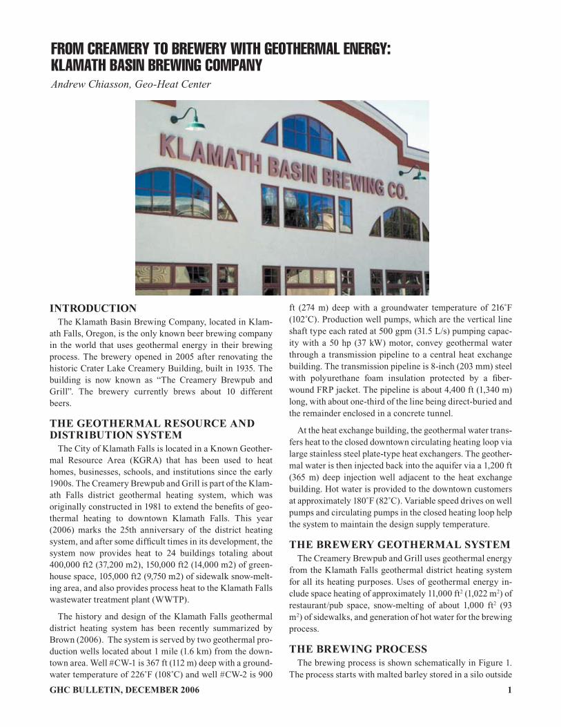
From Creamery to Brewery with Geothermal Energy: Klamath Basin Brewing Company
New Greenhouses in Klamath Falls New Snow Melt Projects in Klamath Falls, OR “Gone Fishing” Aquaculture Project – Klamath Falls, Oregon Greenfuels of Oregon: Geothermal Energy Utilization in Biodiesel Production Oregon Trail Mushrooms Chiloquin Community Center – Chiloquin, Oregon Residential Downhole Heat Exchanger – Klamath Falls, Oregon Merle West Medical Center – Klamath Falls, Oregon
Klamath County Vandenberg Road Complex REACH, Inc. Juniper Processing Plant - Klamath Falls, Oregon Inn of the Seventh Mountain - Bend, Oregon
Geothermal Technologies Program Oregon Factsheet Geo-Heat Center Publication for Oregon
�6 GHC BULLETIN, JUNE 2007
“CHILL OUT” - OREGON INSTITUTE OF TECHNOLOGY IS A WINNERJohn W. Lund and Toni Boyd, Geo-Heat Center, Oregon Institute of Technology
The National Wildlife Federation (NWF) hosted the first annual national competition called “Chill Out! Campus So-lutions to Global Warming” with their partners, the Earth Day Network, Campus Climate Challenge and the Society for College and University Planning. The nation-wide con-test was held throughout the fall and winter of the 2006-2007 school year. The “Chill Out” competition seeks to advance and celebrate the innovators of global warming solutions on college and university campuses all across the country. The purpose of the contest was to spotlight solutions to global warming on campuses and to share these with a national au-dience. Students, faculty or staff could either submit a short
OIT’s geothermally heated fountain.
written blurb on the contest entry website or a short video segment on the linked YouTube site. Details on the contest can be found at www.nwf.org/chillout (you can also access the contest through NWF’s Campus Ecology website at www.nwf.org/campusecology).
The following is what John Lund submitted to the contest:
“CHILL OUT! CAMPUS SOLUTIONS TO GLOBAL WARMING”
OREGON INSTITUTE OF TECHNOLOGY 3201 CAMPUS DR.
KLAMATH FALLS, OR 97601
Oregon Institute of Technology, a state college of the Oregon University System, was founded in 1947. Due to high energy costs on the original campus, a new campus was constructed to take advantage of geothermal energy that was known to exist in the community. In the early 1960s, three deep wells were drilled taping geothermal hot water at 192˚F (89˚C). This hot water now heats the entire campus of about 650,000 sq. ft. (60,000 sq. m) saving about $1,000,000 annually in heating and domestic hot water costs. No other source of energy is available for heating thus; the campus is entirely energy inde-pendent of fossil fuel sources. The campus also uses the geo-thermal energy for melting snow on stairs and handicap ramps. The installed capacity of this system is 6.2 MWt and the annual energy use is about 47 billion Btus (14 GWh), saving 10,000 tonnes of CO
2 emissions annually (compared to producing it
from petroleum).
�7GHC BULLETIN, JUNE 2007
This year, the campus administration is proposing to drill a well (5,000 to 6,000 ft – 1,500 to 1,800 m) deep into a fault that is known to have a geothermal resource around 300˚F (150˚C), to generate electricity. If this is successful, a one megawatt (MWe) geothermal power plant of either a flash steam or binary type will be installed to provide all the electricity needs on cam-pus. This will provide an additional savings of around $500,000 and reduce CO
2 emissions by about 16,000 tonnes annually
(compared to producing it from petroleum). The campus would then be 100% “green” by producing all of its energy needs from geothermal resources.
In addition, the campus will construct a geothermally heat-ed greenhouse and aquaculture facility to train interested stu-dents and potential developers in the use of geothermal energy for agricultural purposes.
Wachusett Community College, Gardner, Massachusetts; Monmouth, West Long Branch, New Jersey; Richard Stockton College, Somers Point, New Jersey; University of California at Santa Barbara; Oberlin College, Oberlin, Ohio; and Lawrence School, Lawrence, New Jersey.
The National Wildlife Federation video team visited cam-pus in March and filmed an interview with President Martha Anne Dow, Geo-Heat Center Director, John Lund, and Geo-Heat Center Engineer and OIT graduate Toni Boyd. They also filmed various geothermal uses on campus. This short video can be viewed on the National Wildlife Federation website: www.nsf.org/chillout.
The live “Chill Out” webcast which was broadcast to over 160 college campuses throughout the country brought to-gether thousands of college students, faculty and staff to cel-ebrate real and practical solutions to global warming taking places on colleges today. It featured a special message from Al Gore to colleges and universities, the winning campuses and an interactive panel of sustainability heroes.
Toni Boyd, of the Geo-Heat Center, represented the cam-pus at the live webcast in Washington, D.C. on April 18. She participated in one of two panel discussions during the live webcast with the other seven winners.
According to NWF, the nation’s over 4,000 colleges and universities manage over 5 billion ft2 of space and spend ap-proximately $18 billion annually on energy costs and emit more than 19 million metric tons of CO
2 annually. The NWF
estimated that the winning schools saved approximately $6 million annually along with eliminating over 20,000 tons (40 million pounds) of CO
2 from the atmosphere. Table 1
shows the conservative estimate made by NFW of CO2 and
cost savings.
Table 1. NWF Estimated CO2 and Cost Savings
Campus CO2 Reduction Annual Tons
Annual Savings
California State University -Chico
100 $100,000
Mt. Wachusett CC 1,909 $500,000
Monmouth University 166 $150,000
Richard Stockton College $433,500
Oregon Institute of Tech 11,000 $1,000,000
University of California - SB 8,150 $3,700,000
Oberlin College 140 $66,000
Lawrenceville School (HS) 199
Totals 21,664 $5,949,500
The eight winners and a brief explanation of their written blurb, from NWF website, follow:
California State University—Chico, CA: Chico State has committed to focusing on institutionalizing sustainability into the education of students. Two buildings are registered
Snow melted stairs.
The Geo-Heat Center was established on campus in 1974 to provided information dissemination and technical assistance for persons and organizations nation-wide and internationally to develop and utilization geothermal energy (website: http://geoheat.oit.edu). The Center staff also provides tours of the campus and community geothermal uses to educate students and interested investors in the benefits of geothermal energy, as well as assisting in the development of the geothermal uses. The proposed power plants, greenhouse and aquaculture fa-cilities will also be used as a training facility and showcase to help transfer geothermal use to other locations throughout the country. Even though, high temperature geothermal energy is generally only available in the western states, the Geo-Heat Center also provides information and training in geothermal (ground-source) heat pumps that can be installed anywhere in the country as they only require normal ground and ground-water temperature to be utilized for both heating and cooling. Our staff of four people has provided technical assistance on geothermal energy use to every state in the Union and well as over 50 countries.
In March 2007, the winning campuses of the contest were notified. In addition to grants and other prizes, winning campuses were to be featured in a national broadcast on the week of Earth Day (on April 18, 2007 at 3:00 eastern). Oregon Institute of Technology was one of the eight winners, and was requested to participate in a live webcast in Washington, D.C. on April 18, 2007. The other winning campus were California State University, Chico; Mount
�8 GHC BULLETIN, JUNE 2007
with LEED, and all new buildings constructed will meet LEED silver requirements. A 300 kW solar array was in-stalled on two campus rooftops. Students have taken the lead to promote sustainability on campus, through projects such as: creating a student fee to fund sustainability projects, ret-rofitting a residence hall, networking with the Chico com-munity to create sustainability service learning programs, and installing energy saving software on computers.
Mount Wachusett Community College, Gardner, MA: The college conversion of its all-electrical campus to a bio-mass hydronic district heating system has drastically re-duced GHG emissions. This conversion demonstrates the use of a sustainable and locally available feedstock and pro-vided unique educational opportunities for students. This project, along with conservation measures, has resulted in a 24% reduction of GHG over the past four years. MWCC has a cumulative water savings of 12.2 million gallons. By elim-inating electricity as a heat source, MWCC has reduced elec-tricity use by 45.97% and saved $2 million. Four new renew-able energy courses are in place. The College is coordinating with 11 states to encourage the use of biobased fuels. The College will soon install a 100kW PV array.
Monmouth University, West Long Branch, NJ: The Uni-versity was just named 2006 New Jersey “Clean Energy School of the Year” after entering a statewide competition. Monmouth completed the largest solar installation east of the Mississippi in summer 2006. The solar panels will save $150,000 and 468,569 kWh/yr. The solar system covers 33,000 ft2 on roofs of four campus buildings. To engage stu-dents, there is a computer generated station that shows en-ergy conservation data in “real time” from the panels. Stu-dents were also involved in installing the solar panels.
Richard Stockton College, Somers Point, NJ: Projects include the world’s largest closed-loop geothermal heating and cooling system, solar PV arrays, and a 200 kW fuel cell. The geothermal unit reduces the school’s electric consump-tion by 25% and natural gas consumption by 70%. The unit has decreased the college’s CO2 emission by 13% since 1990 and saves the school $330,000 annually. The fuel cell was installed in 2002, and provides 10% of the total energy for the campus. The fuel cell is centrally located on campus and is covered in explanatory diagrams making it a teaching tool for students, faculty, staff and other professionals. The PV array (18kW) saves the college $3,500 a year.
Oregon Institute of Technology, Klamath Falls, OR: Due to the high energy costs on the original campus, a new campus was constructed to take advantage of geothermal en-ergy that was known to exist in the community. In the early 1960s, three deep wells were drilled taping geothermal hot water. This hot water now heats the entire campus of 650,000 sq. ft., saving about $1,000,000 annually in heating and hot water costs. The Geo-Heat Center was established on cam-pus in 1974 to provide information and technical assistance for people and organizations to develop and utilize geother-
mal energy, while also providing tours to the campus and community. The campus administration is proposing to drill a well into a fault to generate 100% of the campus’s electric-ity and construct a geothermally heated greenhouse and aquaculture facility to train individuals. The proposals will be used as a training facility and showcase. The staff of four people has provided technical assistance on geothermal en-ergy use to every state in the Union as well as over 50 coun-tries.
University of California, Santa Barbara, CA: In 2005, students from the Bren School of Environmental Science and Management created a Master’s group project entitled “Campus Climate Neutral” and sought to write their thesis on the feasibility of a carbon-neutral campus. One recom-mendation of this study was the certification of the campus’s CO
2 emissions through the California Climate Action Regis-
try. As a public university dealing with tightening budgets, Facilities began to implement energy conservation. Campus-wide lighting retrofits, motion sensors, efficient chillers, and variable frequencies, and efficient chillers are several proj-ects that USCB initiated, resulting in a reduction of CO
2 by
8,100 tons per year. To educate the campus, Facilities oper-ates sustainability and energy specific websites. In addition, the Green Campus Program runs the “Energy Conservation Competition” in residence halls, pitting halls against one an-other to lower energy use.
Oberlin College, Oberlin, OH: A group of students and a professor developed the “Campus Resource Monitoring Sys-tem” (CRMS)—an automated monitoring system and web-site that gathers, processes and displays data on energy and water use in dormitories. The premise is that real-time data can be used to education, and motivate students to conserve resources. For a two week period in 2005, dorms competed to see who could reduce consumption the most, getting 80% of the student body to participate. During that period, stu-dents conserved 68,000 kWh, saving $5,100, and reducing emissions by 150,000 lbs of CO
2. A conservative estimate is
that CRMS will save Oberlin $66,000/yr in electricity costs.
The Lawrenceville School (High School), Lawrence, NJ: Students for Environmental Leadership Coalition (SELF) is promoted the Green Cup Challenge, an inter-scho-lastic energy saving competition between 15 Northeastern boarding schools. Last year was the first year of the Green Cup Challenge, where three schools participated saving 398,370 lbs of CO
2. This year the plans are to increase the
program substantially. SELF made a school-wide presenta-tion regarding global warming and events for the month to promote the Challenge. Projects on campus involve a student biodiesel manufacturing group and the beginnings of an or-ganic garden to provide food for a dining hall.
The event and award is certainly an honor for our campus, and was the only submittal featuring direct-use geothermal energy.
10 GHC BULLETIN, MARCH 1999
THE OREGON INSTITUTE OF TECHNOLOGYGEOTHERMAL HEATING SYSTEM - THEN AND NOW
Tonya L. BoydGeo-Heat Center
INTRODUCTIONOregon Institute of Technology (OIT) is located on a
hill, which gently slopes from the east to the west, in the north-east part of Klamath Falls. The campus has been using geo-thermal water, for its heating and domestic hot water needs,since it was relocated to this location in 1964. It has been incontinuous operation for 35 years and now heats 11 buildings(~600,000 ft2 / 55,700 m2). It is the oldest of the modern geo-thermal district-heating systems, and due to the lack of expe-rience with the design of large systems in the early-1960s, ithas experienced some difficulties through the years. Thesedifficulties have been resolved and the experience has pro-vided a substantial body of information concerning the appli-cability of various materials and designs for low-temperatureuse.
The original system, which provided heating and do-mestic hot water for the five original buildings, consisted ofconstant-speed, water-lubricated lineshaft pumps located inwell pits. The pumps were run manually according to thelevel in the storage tank. The distribution system consisted ofdirect-buried Schedule 40 carbon steel piping which was fieldinsulated with �Foamglas� type insulation and covered with a�mastic� vapor barrier. The geothermal water was used di-
rectly in the buildings� mechanical heating systems; then, theeffluent was disposed of to the surface through the storm drain-age system than eventually emptied into Upper Klamath Lake.Cooling for the campus was accomplished by an electric-pow-ered chiller.
Figure 1 shows a general layout of the OIT system as itis today. Geothermal water for the system is produced fromthree wells at a temperature of 192oF (89oC), which are lo-cated in the southeast corner of the campus. The wells arefrom 1300-1800 ft (400-550 m) in depth. The water is pumpedindividually from each well (total flow of all the wells is 980gpm/62 L/s). The water is then collected in a 4000-gal (15-m3) settling tank in the Heat Exchanger building before it isdelivered to each building via gravity through the distributionsystem according to demand on the system. The settling tank(Figure 2) provides the necessary head for the gravity flowsystem and allows the fines from pumping to settle out of thewater. The heat exchanger building also housed a fuel-oilboiler from the old campus as a backup; but due to lack ofuse, it was dismantled several years ago. The geothermal sys-tem saves approximately 11,000 bbl (1650 tonnes) of oil or$225,000 each year.
2,7 ��
2,7��
2,7 ��
2,7 ,1-��
2,7,1-��
25 (*21�,167 ,7 87 (
2)�7( &+12/2*<
3K\V LFD O
3 ODQW
& RUQ HWW�+ D OO
3X UY LQH
+D OO
6 HPR Q
+D OO
6 RX WK
+D OO
2Z HQ V �
+ D OO
/ LE U DU\
& RO OH FWLRQ� 7D QN
D QG �%RRV WHU�3 XPS V
& KL OOHU
6 QH OO�+ D OO
5 H V LG HQF H �
� +D OO
& ROOH J H
8Q LRQ
3 �( �
% X LOG LQJ
6 WDG LX P
+H D W�( [FK DQJ H U
% X LOG L QJ
6 QRZ P HOW
6 \V WHP V
' LUHF W�% XUL HG
7XQQH O�6\VW HP
1
6 QRZ P HOW
6 \V WHP V
Figure 1. General layout of the OIT geothermal system.
GHC BULLETIN, MARCH 1999 11
Figure 2. The 4000-gal (15-m3) settling tank located in the Heat Exchanger building.
THE PROBLEMS ENCOUNTEREDAND THE SOLUTIONSPumps
After approximately six years of operation, a major re-design of the pumping system was carried out. The originalconstant-speed, water-lubricated lineshaft pumps, were virtu-ally the same as cold-water irrigation pumps and were locatedin wellhead pits. Placing the pumps in the pits didn�t allow forair circulation which lead to overheating and condensation prob-lems. The earlier pumps also didn�t provide for the expansionof the piping in the well; therefore, the lineshaft had to be pre-heated to produce sufficient clearance before the pump wasstarted. This meant one pump had to be kept running all thetime. The pumps also experienced other failures. The originalbronze impellers were attached to the shaft with collets andthe failures occurred when the impellers detached from theshaft. The most serious problem was related to the failure ofthe shaft bearings. A number of bearing types were used, butnone proved to have acceptable lifetimes. It was reported thatthe bronze bearings �burned up,� and the rubber and teflonbearings �swelled.�
Figure 3. One of the pumps and variable-speed controllers with the housing removed.
During the redesign of the pumps, extra lateral bowlswere installed to eliminate the need for shaft preheating. Theimpellers were attached with both keys and collets. At thispoint, it was also decided to isolate the bearings from the geo-thermal water using an oil-lubricated enclosed lineshaft arrange-ment. To help with the overheating and condensation prob-lems, it was decided to raise the pumps to ground level andenclosed them in housing (Rafferty, 1989). Figure 3 showsone of the pumps with the housing removed.
Distribution SystemThe original distribution system consisted of direct-bur-
ied Schedule 40 carbon steel piping, field insulated with�Foamglas� insulation and covered with a �mastic� vapor bar-rier. This piping system suffered internal and exterior corro-sion. The external corrosion was due to the expansion andmovement of piping which caused the mastic vapor barrier tobreak. This failure allowed groundwater and salt water fromdeicing to come in contact with the piping, resulting in theexternal corrosion. After 14 years of service, an examinationof the piping revealed an internal buildup of scale. The scaleconsisted of mainly silica and iron oxide with the iron oxidebeing closest to the pipe. In many places, the piping wall thick-ness was reduced to one-third of its original thickness. Thefact that the main settling tank was vented to the atmospherepermitted oxygen to enter the system, which promoted the in-ternal corrosion. The storm sewer system used for disposal ofthe effluent also encountered failures. This part of the systemconsisted of cast iron and carbon steel piping located in thebuildings, galvanized culverts from the buildings to the mainline, and concrete culverts in the main line. All of the failuresoccurred in sections with galvanized culverts. This could havebeen a result of dezincification (galvanized coating removed)and eventually corrosion of the unprotected steel surface(Rafferty, 1989).
In response to the piping failures, it was decided to con-struct a new distribution system and a dedicated collection sys-tem along with the construction of utility tunnels to connect allthe buildings. The design of the tunnel (6 ft x 6 ft / 2 m x 2 m)provides access for maintenance personnel and space for othercampus utilities. During construction the concrete was formedand poured in place to allow for forming around building foun-dations and utility pipes running at an angle to centerline (Fig-ure 4). The floor of the tunnel is 8 in. (20 cm) thick and thesides 6 in. (20 cm) thick. The pipes are held to the side withpipe clamps and Unistrut hangers. In some cases, the tunnelalso serves as a sidewalk; thus, snow-melting is enhanced dueto the heat loss through the system. The cost of constructingthe tunnel system (including excavation and backfill) was ex-tremely high at about $160/lf ($525/m), which didn�t includethe cost of the piping. The cost of the piping varied from $15/ft ($50/m) for 6-in. (15-cm) diameter to $22/ft ($72/m) for 8-in. (20-cm) diameter pipe. When new extensions to the tunnelsystem were added, a 6-ft (2-m) diameter corrugated galva-nized steel culvert was used instead of concrete. Its estimatedcost was only 25 percent of the cost for concrete tunnels (Lundand Lienau, 1980).
12 GHC BULLETIN, MARCH 1999
Figure 4. View of the tunnel under construction.
Heat ExchangersIn the original design, the geothermal water was used
directly in each of the building mechanical systems. This �oncethrough� approach eliminated the need for circulation pumpsin the buildings. The direct use of the geothermal fluids causedproblems due to the corrosive nature of the water. The origi-nal chemical analysis of the water failed to consider the effectof H2S (hydrogen sulfide) and NH4 (ammonia) on the copperand copper alloys used in the mechanical system. There werea number of different types of failures identified that occurredas a result of using the water directly. The most importantones are listed below:
� Failure of the 50/50 tin/lead solder connections, � Rapid failure of 1% silver solder, � Wall thinning and perforation of copper tubing was
a common occurrence, � Control valve failures where plug (brass) was
crimped to the stem (stainless steel). The threadedones experienced no problems, and
� Control valve problems associated with packingleakage.
thermal water at 100 gpm (6.3 L/s) and the building water at54 gpm (3.4 L/s). The building water is then circulated throughfinned-tube pipe heat convectors located along the outside wallsof the building. The second loop provides 30,000 Btu/hr (30MJ/hr) using geothermal water at 25 gpm (1.4 L/s) and build-ing water at 12 gpm (0.65 L/s). The building water is thencirculated through reheat coils, which provides heating througha forced-air system for the interior of the building (Lund andLienau, 1980).
Figure 5. The College Union heat exchanger.
Fluid DisposalDischarge to the surface was the original approach for
disposal of the geothermal effluent. Although surface dischargeis the simplest and least expensive option, there were severalpossible potential problems. The discharge temperature of thewaste effluent was still quite high (135oF/57oC-winter and170oF/77oC-summer) when it was delivered to the ditch. Thismethod presented a safety hazard. A local city ordinance waspassed which banned surface disposal and required all opera-tions in the city to establish an injection program by 1990.OIT now has two injection wells to compile with the ordinance.The first injection well was drilled using standard mud-rotarytechniques, and the second well used a combination of meth-ods with air drilling in the injection zone. During the initialpumping test of the first injection well, the maximum obtain-able pumping rate was only 200 gpm (12.6 L/s). It was be-lieved that a considerable amount of drilling mud had invadedfractures in the primary production zones. The well wasacidized (13% hydrochloric acid, 3% hydrofluoric acid) twice;this increased the capacity from 200 to 400 gpm (12.6 to 25.2L/s). Analysis of test data indicated that the aquifer was stillclogged with drilling mud at about 25 times the effective ra-dius of the well. The maximum injection rate was estimated tobe 600 gpm (37.8 L/s). The second injection well easily handles1,000 gpm (63 L/s) and could possibly accept as much as 2,500gpm (158 L/s) at 50 psi (3.4 bar) injection pressure is allowedat the wellhead. This well is being used as the primary injec-tion well. Experience with these injection well suggest that airdrilling can be quite beneficial in terms of subsequent wellperformance (Lienau, 1989).
To address these problems, it was decided to isolate thegeothermal water from the building heating systems using plateheat exchangers. Based on an analysis study, heat exchangerswith 316 stainless steel plates with Buna-N gaskets were se-lected. The stainless steel heat exchanger used to heat the cam-pus swimming pool failed within the first three years of opera-tion. This failure occurred on the pool�s water side of the heatexchanger, probably as a result of the high chorine content.The pool�s heat exchanger was eventually replaced with tita-nium plates (Rafferty, 1989).
Some of the building systems utilize two loops throughthe heat exchanger. The College Union building plate heatexchanger, shown in Figure 5, utilizes two loops. The firstloop provides 1,350,000 Btu/hr (1,350 MJ/hr) using the geo-
GHC BULLETIN, MARCH 1999 13
NEW ADDITIONS TO THE SYSTEM
Snowmelt SystemThe newest additions to the OIT system are two sections
of sidewalk snowmelting located by the Residence Hall. Thisbrings the total amount of sidewalk snowmelting to 2,300 ft2
(214 m3). The other sections include the wheelchair ramp infront of South Hall and a couple of stairwells (Figure 6) lead-ing to upper sections of the campus. All systems utilize 5/8-in.(1.6 cm) diameter cross-linked polyethylene tubing (PEX). Thewheelchair ramp has four loops with the tubing spaced 10 in.(25 cm) apart. The stairs has three loops with the tubing tied tothe existing stairs. Figure 7 shows the placement of tubing ona stairwell before the form work was added. The systems shouldbe able to maintain a slab surface temperature of 38oF (3oC) at-5oF (-21oC) air temperature and 10 mph (16 km/h) wind whenthe entering 50/50 propylene glycol/water temperature is144oF(62oC). Each stair section uses a brazed-plate heat exchangerto isolate the glycol-filled snowmelt loop. The new snowmeltsystems installed have slab temperature sensors which willactivate the system when the outside air is 30 oF (-1oC)(Geothermal Pipeline, 1994).
Figure 6. One of the stairwell leading to the College Union.
Figure 7. Placement of the snowmelt tubing before the formwork was added.
Purvine HallPurvine Hall utilizes the geothermal waste effluent from
the rest of the campus for its space heating and domestic hotwater heating. The temperature of the effluent as it enters thebuilding is around 155oF (68oC) and leaves at a temperature ofaround 130oF (54oC). The main components of heating sys-tem include a 4,000-gal (15-m3) storage tank, circulation pumpsand heat exchangers. On the building heating side, space heat-ing is accomplished by 54 variable air volume terminalsequipped with hot water coils (Fields, 1989).
Absorption ChillerA lithium-bromide absorption chiller was installed in
1980. It has a nominal 312 ton (1095 kW) capacity; but due tothe low temperature of the water entering the system (192oF/89oC), it only produces 150 tons (526 kW) of cooling. Thechiller requires 685 gpm (37.8 L/s) of geothermal fluid andonly takes a 20oF (11oC) delta T out of the water. Recordedinstallation cost for the chiller was $171,300. The geothermalchiller supplies a base cooling load to five campus buildingsor 277,300 ft2 (25,800 m2). The original electrical centrifugalchiller is now being used for peaking above the capacity of theabsorption chiller. Since the geothermal water is used directlyin the generator tubes of the absorption chiller there is a poten-tial for corrosion to occur. The generator tubes are constructedof 90-10 cupro-nickel; but, no failures have occurred in thepast 18 years (Lund and Lienau, 1980). Due to the low effi-ciency and high water usage, the absorption chiller will be re-placed this summer with a centrifugal water chiller.
REFERENCESFields, Paula G., 1989. �Purvine Hall Geothermal Heating
System,� Geo-Heat Center Quarterly Bulletin, Vol.11, No. 4, pp. 16-17.
Geothermal Pipeline, 1994. �Geothermal Wheelchair RampInstalled at OIT,� Geo-Heat Center QuarterlyBulletin, Vol. 16, No. 1, pp. 24-25.
Lund, John W. and Paul J. Lienau, 1980. �New GeothermalConstruction on the OIT Campus,� Geo-HeatCenter Quarterly Bulletin, Vol.5, No. 3, pp. 21-23.
Rafferty, K. 1989. �A Materials and Equipment Review ofSelected U.S. Geothermal District Heating Sys-tems.� Geo-Heat Center, Klamath Falls, OR.USDOE Contract # DE-FG07-87-ID 12693.
Gibson, Raymond, 1999. Personal communication. OregonInstitute of Technology.
Masl, Bruce, 1999. Personal communication. OregonInstitute of Technology.
�0 GHC BULLETIN, JUNE 2007
Klamath Falls Geothermal District Heating System at 25 Years Brian Brown P.E., Brian Brown Engineering, Klamath Falls, OR
Figure 1. Klamath Falls Geothermal District Heating system location map, 2005
ABSTRACTIn 1976 the OIT Geo-Heat Center began investigating the
feasibility of developing a geothermal district heating sys-tem to serve the Klamath Falls downtown. The district heat-ing system was installed in 1981. Startup and operational problems prevented reliable operation until 1991. In 1992, the city began marketing the district heating system to other buildings in the downtown area.
By 2006 the system approached the original design capac-ity, and more growth is planned. After 25 years, the system is beginning to realize the economic benefits envisioned by the original feasibility studies in 1977.
INTRODUCTIONThe City of Klamath Falls, Oregon, is located in a Known
Geothermal Resource Area (KGRA) that has been directly used to heat homes, businesses, schools, and institutions since the early 1900s. In 1976, Klamath Falls and Klamath County became interested in establishing a geothermal dis-trict heating system to extend the benefits of the geothermal resource to government buildings and businesses in down-town Klamath Falls. This led to construction of the district heating system in 1981. After a difficult start-up period, the
system has provided reliable service since 1991. For more information on the system development, see Lienau, et al., (1989 and 1991).
The district heating system was originally designed for a thermal capacity of 20 million Btu/hr (5.9 MWt). At peak heating, the original ten buildings on the system utilized only about 20 to 25 percent of the system thermal capacity.
Total annual heating revenue from those buildings in 1991 was about $23,800, which was inadequate to sustain system operation. This led the city to begin a marketing effort in 1992 to add more customers to the system (Rafferty, 1993).
The Klamath Falls geothermal district heating system cur-rently serves process heating at the Klamath Falls wastewa-ter treatment plant (WWTP), 24 buildings totaling about 400,000 sq. ft., greenhouses totaling 150,000 sq. ft., and about 105,000 sq. ft. of sidewalk snowmelt systems. Figure 1 shows the existing district heating service area.
The year 2006 marked 25 years since completion of the district heating system construction. This paper is intended to provide a retrospective on system development and les-sons learned. The author has provided geothermal engineer-ing consulting to the city since 1992.
��GHC BULLETIN, JUNE 2007
District Heating System Timeline• 1977: Feasibility study. (Lienau, et al., 1977).
• 1981: Construction of downtown district heating system completed.
• 1982: Construction of Michigan Street district heating system to serve low income neighborhood of 120 homes, funded by HUD. Only about 10 homes connected.
• 1981-1984: Public opposition delayed operation of the sys-tem until an aquifer study was completed.
• Nov. 1984: System operation begins.
• Feb. 1986: System operation halted after multiple failures of the distribution piping.
• Jan. 1991: System operation restarted after reconstruction of distribution piping.
• 1992: Beginning of marketing effort to add customers (Rafferty, 1993).
• Sep. 1993: Earthquake damages four County buildings, about half of connected heating load shut down.
• Nov. 1993: Pipeline extension to the Ross Ragland Theater completed; allows connection of six new customers.
• 1995-1998: Development of the Klamath Falls Main Street streetscape project, with geothermally heated sidewalks and crosswalks (Brown, 1995).
• 1996: Engineering evaluation of system condition, load, and capacity (Brown, 1996).
• 1999: Rehabilitation of the upper production well, CW-1.
• 2000: Repair of the injection well piping due to a corro-sion failure.
• 2000: Addition of new circulation pump, CP-2.
• 2000-2001: Extension of district heating system to serve the Klamath Falls wastewater treatment plant and 100,000 sq. ft. greenhouse facility.
• 2001: Michigan Street system abandoned.
• 2003: Evaluation of capacity and improvements needed to support an expansion of the greenhouses (now at 4.0 acres). Partially funded by NREL.
• 2003-2004: System improvements including new heat ex-changers, new automatic controls, improved pipe tunnel and vault ventilation, replacement of pipeline expansion joints, rehabilitation of the lower production well, CW-2. Partially funded by NREL.
• 2006: Addition of circulation pump, CP-3, to match the pump added in 2000.
• 2006: Expansion of the district heating system mains and development of a new sidewalk snowmelt system to serve the Timbermill Shores development on a former mill site.
The Klamath Falls district heating system is beginning to be financially viable and self-sustaining after 25 years of op-eration. The path to that point has been long and difficult, but thanks to the long-term commitment of the people of Klam-ath Falls, a difficult beginning has been turned into a suc-cessful system.
LESSONS LEARNED The geothermal district heating system design and mate-
rials selection was based on a preliminary design study in 1979 by LLC Geothermal Consultants, Klamath Falls, OR. (Lund, et al., 1979). The engineer of record, Balzheiser/Hub-bard & Associates, implemented the preliminary design rec-ommendations with minor modifications.
Photo 1: Drilling of CW-1 well (Geo-Heat Center)
Photo 2: Well Pump (Brown)
Production Wells Production well pumps are vertical line shaft pumps, oil
lubricated, with variable-speed drives. The well pumps as originally designed were rated for 500 gpm each, and pow-ered by 50 hp motors.
The well pump for CW-1 was removed and rehabilitated in 1999 and CW-2 was rehabilitated in 2004. Inspection of the pumps showed significant corrosion of the steel column pipe at and above the water level, but no corrosion signifi-cantly below the water level. The corroded column pipe was replaced and the rest of the column pipe was reused. The pump bowls, line shaft, bearings, and shaft tube were in good condition and were reused.
�2 GHC BULLETIN, JUNE 2007
Photo 3: Production Pipeline and Tunnel Construction (Babcock)
The original 50 hp motors and Nelson fluid drive were removed and replaced with an adjustable frequency drive and a 75 hp motor. The adjustable frequency drive and larger motor give the capability to over-speed the pump by about 20% from the nominal design speed of 1750 rpm to 2100 rpm. The increased pump speed can provide about a 20% increase in pumping.
The original system used Nelson fluid drives for variable speed operation. City water which was used to cool the drive was discharged down the well. That cooling water kept the outside of the column pipe wet and introduced oxygen into the well, promoting corrosion. Replacement of the Nelson drives with adjustable frequency drives allowed elimination of the cooling water flow and the resulting corrosion.
Geothermal Transmission Pipeline Geothermal flow from the production wells is conveyed to
the heat exchanger building through an 8-inch steel pipeline, about 4400 feet long. The pipe is insulated with polyure-thane foam insulation, protected by a fiber-wound FRP jack-et. About one-third of the pipeline is direct-buried; the rest is enclosed in a concrete pipe tunnel.
sion joints, and pipe anchors where the steel has been ex-posed to moisture. The expansion joints and pipe tunnel were intended to protect the pipe by providing a dry environ-ment. However, the atmosphere in the vaults and tunnel was extremely humid because of inadequate ventilation and in-frequent maintenance of the vault drains. Moisture would condense on the vault and tunnel ceilings and then rain down on the pipe. There is evidence of past flooding, resulting in direct contact of water and sediment with the pipe.
The city installed two six-inch vent pipes to each expan-sion joint vault, with one pipe connected high in the vault and the other low. The vent pipes provide thermal and wind-driven ventilation of the vaults, which reduce the high hu-midity and condensation. Tunnel ventilation has been im-proved by installing a blower at the heat exchanger building to force air into the tunnel and a larger relief vent at the far end of the tunnel.
The city has had to repair two corrosion failures in the direct-buried portion of the pipeline. It appears that the FRP jacket is beginning to fail and allow soil moisture to contact the pipe. The City plans to replace the steel pipeline with pre-insulated ductile iron pipe as funds allow.
District Heating Distribution The district heating distribution piping is a closed loop
system with both supply and return pipelines. Almost half of the original system length was 10-inch, pre-insulated steel pipe. The rest of the piping, 8-inch and smaller, was key-lock fiberglass pipe.
The fiberglass pipe joints failed after the first heating sea-son, possibly due to defective epoxy on the factory-glued joints, and were entirely replaced with pre-insulated ductile iron pipe. Where the ductile iron pipe has been inspected, it remains in good shape after 15 years of service.
The steel portion of the pipeline was protected by the insu-lation system and cathodic protection anodes, which have not been checked since construction. There have been recent corrosion failures in the steel pipelines; likely caused by fail-ure of the FRP jacket coupled with diminished cathodic pro-tection. The city plans to replace the pipe with pre-insulated ductile iron as funds allow.
Some customer service connections were installed using unprotected steel piping. Those connections have tended to fail after about ten years. Improved corrosion protection is being used on new and repaired connections.
District Heating System Controls The control system was originally designed to maintain
the district heating supply temperature at a constant 180˚F by controlling geothermal production and the flow through the heat exchanger. On decreasing temperature of the sup-ply water, the system was intended to increase the geother-mal production by increasing the well pump speed and au-tomatically starting the second well pump if needed. On
Pipe expansion in the direct-buried section is accommo-dated by expansion joints with stainless steel bellows, lo-cated in expansion joint vaults. Pipe expansion in the tunnel is accommodated by expansion joints and pipe roller-guides.
The interior of the pipe is in excellent condition with min-imal corrosion. The exterior of the pipe has suffered varying degrees of corrosion damage, particularly at fittings, expan-
��GHC BULLETIN, JUNE 2007
increasing temperature of the supply water, the system would reduce production, then modulate a three-way valve to bypass district heating water flow around the heat ex-changer.
The geothermal water temperature is above boiling tem-perature at the project elevation, so a backpressure valve and control was designed to maintain enough pressure on the geothermal production piping to prevent flashing to steam in the system.
The original pneumatic control system was not capable of meeting the design control objectives. The fully auto-matic temperature control operation resulted in serious os-cillations of well pump speed and starting/stopping. The resolution was to operate the well pumps manually, and limit the automatic temperature control to the three-way valve. The backpressure control was also unstable, partial-ly due to inappropriate valve selection.
The control system was upgraded in 2003 to modern digital controls, using Allen Bradley programmable logic controls (PLC). The telephone telemetry link to the pro-duction wells was replaced with spread-spectrum radio te-lemetry. The control system is fully integrated with the city control system for water and wastewater system operation.
The original temperature control and backpressure con-trol concepts were retained with the new controls. The in-creased power and tuning capability of the modern controls have largely been able to tame the unstable control loops.
Back-pressure control is a difficult control service, with the valve required to operate over a wide flow range, con-trolling hot fluids that can flash to steam or cause cavitation on the downstream side of the valve. There remains some instability in the backpressure control even with the new control system and a new control valve. More stable opera-tion can likely be achieved by reprogramming the controls to operate the valve for temperature control, and control the well pumps to maintain a pressure set-point. On de-creasing temperature the controls would open the valve, resulting in increased flow and reduced pressure. The con-trols would then increase the pump speed to compensate.
CAPACITY AND LOAD The capacity of a closed-loop district heating system is
fundamentally different than the capacity of a potable wa-ter system. The purpose of a water system is to deliver wa-ter, which is consumed in some way and not returned to the water system. What the customer does with the water is not a major consideration; the water system is sized for the ca-pacity to deliver given design flow.
A district heating system is designed to deliver heating energy. The water flow is merely a means to convey the energy. The capacity to deliver heat is limited both by the flow capacity of the system and what the customer does with the heating water before sending it back. The capacity
of the system is thus very much constrained by the action of the customers. The amount of heat delivered by the water depends on both the flow rate and the temperature change of the water. This can be expressed by the equation:
ENERGY (BTU/HR) = FLOW (GPM) x ΔT (°F) x 500
Flow is essentially fixed by the hardware selected in the design: the pumps, pipes, control valves, heat exchangers, production wells, and injection well. Any significant in-crease in the flow requires larger equipment and increased power to operate.
Temperature change of the heating water (delta-T) is equally important to the delivery of heat. The delta-T is af-fected by physical constraints such as the temperature of the heat source, the temperature requirements of the heat load, and the sizing of the heat transfer device. The main cause of low delta-T is failure to properly control heating water flow, with the consequence of reduced thermal ca-pacity and higher than necessary pumping costs.
The Klamath Falls geothermal district heating system was designed with a thermal capacity of 20x106 Btu/hr (5.9 MWt), based on 1,000 gpm of loop flow, 1,000 gpm of geo-thermal flow, and a design delta-T of 40°F. The load on the district heating system is approaching the original design thermal capacity. According to the system data log, the peak load for the 2005-2006 heating season was about 14.9x10⁶ Btu/hr, on December 1, 2005 at 7:58 AM, at an outside air temperature of 10°F. Geothermal flow was 764 gpm. Loop flow was 819 gpm.
In another sense, the system was operating at near capac-ity in 1993 when the loop flow was about 900 gpm at a maximum 10°F delta-T, or in 1996 at a loop flow of 850 gpm and 16°F system delta-T. The ability to add customers to the system and thus increase revenue has primarily been possible because of improved flow control at customer con-nections, increasing the delta-T and freeing up flow capac-ity.
Recent improvements were intended to increase the nominal system capacity to about 36x106 Btu/hr (8.5 MWt), based on 1,200 gpm pumping capacity and 60°F delta-T. Some of that increased capacity is due to new heat exchang-ers and increased circulation pump capacity. However, most of the capacity increase is dependant on improvement in system delta-T. Proposed measures to achieve improved delta-T include:
• Continued improvement of flow control at existing cus-tomer connections
• Cascading flow from higher temperature uses to lower temperature users. For example, operating snowmelt sys-tems off the district heating loop return line rather than supply line.
• Designing new connections to the system for a higher del-ta-T of 60°F.
�� GHC BULLETIN, JUNE 2007
ECONOMICS
Original Projections The geothermal district heating system was designed to
initially serve 14 government buildings with planned expan-sion to serve additional buildings on 11 commercial blocks along the route, then the entire 54-block downtown commer-cial district. The anticipated system heating loads for the planned construction phases were: (Lienau, 1981)
Phase Description Peak heat load Btu/hr
I 14 Government Buildings 21 x 106
II 11 Commercial Blocks 34.8 x 10⁶
III 54 Commercial Blocks 143 x 106
The system feasibility study was conducted during the late 1970s energy crisis, when there was sharp run-up in the cost of natural gas and other energy. Figure 2 shows a 20-year life-cycle cost comparison of the proposed project on a unit energy basis. (Lienau, 1981) Key assumptions included:
• System peak load: 34.8 x 10⁶ Btu/hr (Phase II)
• Annual energy use: 60 x 109 Btu
• Capital cost: $3,753,259 at 8%
• O&M 6.2% of capital; inflated at 7%/year
• Natural gas inflation: 14.6% to 17.6% /year
The analysis calculated that the cost of the geothermal en-ergy would match natural gas at about year five, at a cost of about $7.00 per 106 Btu, and simple payback would occur at ten years.
The first hurdle was concerns by home owners about the impact of operation of the geothermal system on their pri-vate wells. Klamath Falls has hundreds of private homes heated by private geothermal wells. The concern was that the city system would lower the water level and/or reduce geothermal temperatures, negatively affecting the private wells. The home owners initiated a city ordinance that ef-fectively prohibited operation of the newly constructed dis-trict heating system. That problem was resolved by extensive aquifer testing, including full operational testing that showed no negative impact. However, start-up of the district heating system was delayed by three years to November 1984.
The next hurtle was failure of the fiberglass distribution system piping after only one heating season. The city was faced with the question: do they rebuild, or shut the system down. The decision was to borrow the needed funds and re-build the distribution system. The system was restarted in January 1991.
Meanwhile, the cost of natural gas dropped from a high of $0.627/therm (105 Btu) in October 1982, to a low of $0.378/therm in December 1991. See Figure 3. That compares to a projected cost of about $1.10/therm at year ten in the original economic analysis. The total heating revenue for 1991 was about $23,800, which was well below the cost of system op-eration.
The city was again faced with a choice: shut the system down, or subsidize operation while attempting to grow the connected load and revenue. The city began a marketing push in 1992, and over the following 13 years the system load has been increased to near the original Phase I design capacity. The cost of conventional energy has also increased, making the renewable geothermal energy more valuable.
Figure 2. Phase II Unit Energy Cost Comparison (Lineau, 1981)
Initial Operation Phase I was funded and constructed as a demonstration
project, with most of the cost covered by grants. On that ba-sis, the expectation was that the economics would be better than the Phase II analysis. Unfortunately, the system did not meet those expectations.
Current Status The geothermal district heating system provides a signifi-
cant financial impact on the local community. For 2005, the metered geothermal energy sales was about 26.1x10⁹ Btu, and un-metered building energy use was about 5.3x10⁹ Btu, for a total of 31.4x10⁹ Btu. Currently, the commercial natural
Figure 3. Local Natural Gas Cost Trend.
�5GHC BULLETIN, JUNE 2007
gas rate is $1.26353 per therm, or assuming a seasonal con-version efficiency of 67%, about $18.8/106 Btu. The direct economic value of using geothermal energy from the district heating system rather than fossil fuels was about $589,000.
Economic value is also realized indirectly by the contri-bution of the geothermal system to economic growth and downtown revitalization. The availability of geothermal en-ergy was a major factor in the decision of the IFA Nurseries greenhouses to locate in Klamath Falls. The geothermal en-ergy allows IFA to control their energy costs. In return they contribute jobs to the community and tree seedlings for local reforestation efforts. Geothermally heated sidewalk snow-melt systems are a very visible and popular feature of the downtown redevelopment project, which has helped turn around a formerly declining downtown area.
managing system operation, system growth, and customer connection delta-T control.
After 25 years the system operation is at or near opera-tional break-even. The revenue should continue to increase over the next few years as more customers are added and existing unmetered customers are switched to metered ser-vice. The increased revenue should help with funding of other operational needs.
In retrospect, the original economic analysis was not too bad; there was just a 20-year pause in the growth of energy costs, and a 15 year delay in geothermal system expansion. The people of Klamath Falls are to be commended for their perseverance through the lean times.
ACKNOWLEDGMENTS This paper was partially based on work funded by the
National Renewable Energy Lab, Golden Colorado, and the City of Klamath Falls. Opinions expressed in this paper are those of the author. Thanks to John Lund, the OIT Geo-Heat Center, and Brent Babcock (Balzheiser/Hubbard project manager), for their perspective on the original system design and construction.
The economic value of the geothermal district heating sys-tem to the community is clearly significant. The other ques-tion is whether the revenue to the system operator is adequate to cover costs. The city cannot charge the full value of con-ventional energy, or there would be no incentive for custom-ers to connect.
The city metered geothermal rate is set at 80% of the cur-rent commercial natural gas rate, with rate increases limited to no more than 10% per year. The current standard rate is $8.828 /106 Btu. A significant portion of the load is still billed at long-term flat rates negotiated several years ago, of $5.40/106 Btu or $5.60/106 Btu. The 2004-2005 heating sea-son average for metered accounts was $6.15/106 Btu. There are still several unmetered buildings that will be metered within the next couple years.
Total system revenue for the 2004-2005 heating season was $170,012. Direct operating expenses for the same period were $47,403. Additional deferred maintenance costs that should be included in the annual costs include about $15,000 annually for heat exchanger plate cleaning and regasketing, and about $70,000 annual financing costs for about $800,000 in needed pipeline repair and upsizing. The city should also be funding a maintenance reserve and greater staff time for
Lienau, P.; G. Culver and J. Lund, 1977. “Klamath County Geo-Heating District Feasibility Study” prepared for Klam-ath County Commissioners, Geo-Heat Center, Klamath Falls, OR.
Lienau, P., 1981, “Design of the Klamath Falls Geothermal District Heating Network”, ASHRAE Transactions, Vol. 87, p. 2, Atlanta, GA
Lienau, P.; G. Culver and J. Lund, 1989. “Klamath Falls Geo-thermal Field, Oregon, Case History of Assessment, Develop-ment and Utilization”, Presented at Geothermal Resources Council 1989 Annual Meeting, Santa Rosa, CA.
Lienau, P. and K. Rafferty, 1991. “Geothermal District Heat-ing System: City of Klamath Falls”, Geo-Heat Center Quar-terly Bulletin, Vol. 13, No. 4., p. 8-20.
Lund, J. W.; P. J. Lienau; G. Culver and C. V. Higbee, 1979. “Klamath Falls Geothermal Heating District” Report to City of Klamath Falls, LLC Geothermal Consultants, Klamath Falls, OR.
Rafferty, K., 1993. “Marketing the Klamath Falls Geothermal District Heating System”, Geo-Heat Center Quarterly Bulle-tin, Vol. 15, No. 1., p. 4-6.
�GHC BULLETIN, DECEMBER 2006
FROM CREAMERY TO BREWERY WITH GEOTHERMAL ENERGY: KLAMATH BASIN BREWING COMPANY Andrew Chiasson, Geo-Heat Center
INTRODUCTION The Klamath Basin Brewing Company, located in Klam-
ath Falls, Oregon, is the only known beer brewing company in the world that uses geothermal energy in their brewing process. The brewery opened in 2005 after renovating the historic Crater Lake Creamery Building, built in 1935. The building is now known as “The Creamery Brewpub and Grill”. The brewery currently brews about 10 different beers.
THE GEOTHERMAL RESOURCE AND DISTRIBUTION SYSTEM
The City of Klamath Falls is located in a Known Geother-mal Resource Area (KGRA) that has been used to heat homes, businesses, schools, and institutions since the early 1900s. The Creamery Brewpub and Grill is part of the Klam-ath Falls district geothermal heating system, which was originally constructed in 1981 to extend the benefits of geo-thermal heating to downtown Klamath Falls. This year (2006) marks the 25th anniversary of the district heating system, and after some difficult times in its development, the system now provides heat to 24 buildings totaling about 400,000 ft2 (37,200 m2), 150,000 ft2 (14,000 m2) of green-house space, 105,000 ft2 (9,750 m2) of sidewalk snow-melt-ing area, and also provides process heat to the Klamath Falls wastewater treatment plant (WWTP).
The history and design of the Klamath Falls geothermal district heating system has been recently summarized by Brown (2006). The system is served by two geothermal pro-duction wells located about 1 mile (1.6 km) from the down-town area. Well #CW-1 is 367 ft (112 m) deep with a ground-water temperature of 226˚F (108˚C) and well #CW-2 is 900
ft (274 m) deep with a groundwater temperature of 216˚F (102˚C). Production well pumps, which are the vertical line shaft type each rated at 500 gpm (31.5 L/s) pumping capac-ity with a 50 hp (37 kW) motor, convey geothermal water through a transmission pipeline to a central heat exchange building. The transmission pipeline is 8-inch (203 mm) steel with polyurethane foam insulation protected by a fiber-wound FRP jacket. The pipeline is about 4,400 ft (1,340 m) long, with about one-third of the line being direct-buried and the remainder enclosed in a concrete tunnel.
At the heat exchange building, the geothermal water trans-fers heat to the closed downtown circulating heating loop via large stainless steel plate-type heat exchangers. The geother-mal water is then injected back into the aquifer via a 1,200 ft (365 m) deep injection well adjacent to the heat exchange building. Hot water is provided to the downtown customers at approximately 180˚F (82˚C). Variable speed drives on well pumps and circulating pumps in the closed heating loop help the system to maintain the design supply temperature.
THE BREWERY GEOTHERMAL SYSTEM The Creamery Brewpub and Grill uses geothermal energy
from the Klamath Falls geothermal district heating system for all its heating purposes. Uses of geothermal energy in-clude space heating of approximately 11,000 ft2 (1,022 m2) of restaurant/pub space, snow-melting of about 1,000 ft2 (93 m2) of sidewalks, and generation of hot water for the brewing process.
THE BREWING PROCESS The brewing process is shown schematically in Figure 1.
The process starts with malted barley stored in a silo outside
2 GHC BULLETIN, DECEMBER 2006
the building (Figure 2). The blend of malts required for a particular recipe is cracked in a roller mill. The milled malt or “grist” is transported by an auger to the grist hopper above the brewhouse.
The grist is mixed with hot water generated from the geo-thermal source in the mash tank (Figure 3), which starts the process of “mashing”. As shown in Figure 3, the hot water provided by the City geothermal system exchanges heat with a heating loop, which includes a backup/supplemental boiler. The heat exchanger between the primary geothermal water and secondary heating loop is shown in Figure 4.
about 154˚F (68˚C), and depending on the temperature of the grist (which enters the building near ambient outdoor temperatures) , hot water up to 192˚F (89˚C) must be sup-plied. After a few hours, mashing converts starches in the malt to sugars, and then the mash and the sweet liquid called “wort” are transferred to another tank called the “lauter tun”.
Once the mash and wort are transferred to the “lauter tun”, the wort is pumped back to the mash tank which now be-comes the brew kettle. During this step, the “lautering” pro-cess is started, which is done by rinsing the mash with clean hot water at a temperature of about 172˚F (78˚C), generated from the geothermal source. The temperature of the water will shut down the conversion process of starch to sugar so that the wort will not become astringent tasting.
Once the brew kettle is full, the wort is brought to a boil for about two hours using a gas burner. Bittering hops are added at the beginning of the boil, while hops used for aroma and flavor are added toward the end. After the boiling pro-cess, the wort is “whirlpooled”, where the centrifugal force separates the hops from the wort and helps clarify the wort.
The wort is then cooled as it passes through a heat ex-changer on its way to temperature-controlled fermentation tanks kept at 72˚F (22˚C).
The initially cold water on the cold side of the heat ex-changer is recovered at about 182˚F (83˚C) and is pumped to the hot liquor storage tank. During the transfer of the wort, yeast is added which ingests the sugars to produce alcohol and carbon dioxide. Many different strains of yeast are used to give many different flavors of the finished beer. Fermenta-tion takes 3 to 4 days for ales and 1 to 2 months for lagers.
The Klamath Basin Brewing Company does not filter their beer, as it is believed that using “fines” to help clarify the
Figure 2. Photograph of the malted barley silo. This secondary loop provides heat through another plate-
type heat exchanger to the pure water stream used in the brewing process. The desirable temperature of the mash is
Figure 1. Brewing process schematic.
�GHC BULLETIN, DECEMBER 2006
beer results in a more full-flavored beer. The finished beer is carbonated and stored in serving tanks in a walk-in cooler, where it is either kegged or served to customers.
ENERGY CONSUMPTION AND OPERATING COST
City metering of geothermal energy usage by the Cream-ery Brewpub and Grill has just begun in March 2006, so documented geothermal energy use history is limited. Dur-ing March 2006 when a significant amount of space heating and snow-melting were required, the Creamery Brewpub and Grill used about 1,700 therms (179 GJ) of geothermal energy, which cost about $1,360. The avoided cost of natural gas at 80% efficiency and $1.20/therm would be about $2,550. Therefore, the Creamery Brewpub and Grill saved about $1,190 during the month of March 2006 with geother-mal energy.
During the month of June 2006 when most of the geother-mal energy would be used for beer brewing, the Creamery Brewpub and Grill used about 430 therms (45 GJ) of geo-thermal energy, which cost about $344. The avoided cost of natural gas at 80% efficiency and $1.20/therm would be about $645.
Therefore, the Creamery Brewpub and Grill saved about $300 during the month of June 2006, with geothermal ener-gy. It should be noted however, that the geothermal system was shut down sometime in June 2006, so these values may not be representative of a full month’s energy useage.
ACKNOWLEDGEMENTS The Geo-Heat Center wishes to thank the owners of the
Klamath Basin Brewing Company, D. Azevedo & L. Clem-ent, for providing the information for this case study, and D. Beach of Stanford University for the photographs.
Figure 4. Photograph of the heat exchanger between the City geothermal district heating system and the brewery secondary heating loop.
REFERENCES Brown, B. 2006. “Klamath Falls Geothermal District Heating System at 25 years”, Geothermal Resources Council Transactions Vol. 30, pg. 185-190.
Figure 3. Photograph of the mash tank/brew kettle.
NEW GREENHOUSESIN KLAMATH FALLS
John W. LundGeo-Heat Center
A state-of-the-art 50,000-sq ft greenhouse, heated bygeothermal energy, was recently put into operation inKlamath Falls, Oregon (Figure 1). The greenhouse, whichuses technology that has long helped Canada dominate themarket for tree seedlings is operated by IFA Nurseries, Inc.,based in Canby, Oregon. The facility can raise about twomillion seedlings of ponderosa pine, Douglas fir, hemlock andother species, depending upon the demand of customers.Eventually, they plan to have four greenhouses in operation,producing about eight million seedlings a year. A secondgreenhouse is currently under construction and will be readyfor use this fall (Figure 2).
Figure 1. 50,000-sq ft greenhouse currently inoperation.
Figure 2. The second greenhouse underconstruction.
GHC BULLETIN, SEPTEMBER 2002
The operation was located in Klamath Falls to takeadvantage of the geothermal heat available from the city’sdistrict heating system. To attract the business, the city ofKlamath Falls extended their hot water pipeline from thedowntown to the greenhouse, located on the edge of town nearthe South 6th street overpass and city maintenance yard. Theheated water is provided from the supply side of the districtheating system (see Brown, 1999) at 180oF, and the spentwater is then piped to the return side of the district heatingloop. A plate heat exchanger (Figure 3) transfers the heat toa secondary loop using a water-glycol mixture (Figure 4).This loop then provides heat to a series of under-bench fancoils and hot air plastic distribution tubes (Figure 5). IFApays the city for the heat at a rate somewhat less than thecorresponding natural gas rate, which does not fluctuate withthe market.
Figure 3. The main plate heat exchanger.
The seedlings, growing in long rows of Styrofoamcontainers (Figure 6), are watered by long wands that slideacross the ceiling. A computer controls the heat supply,watering, lights and ventilation through opening and closingperimeter curtains and vents in the roof. Controlled lightingand uniform temperatures help the growth rate, as whatnormally would take a year to grow in normal light, grows insix months in this controlled environment. In addition,seedlings grown indoors in containers usually survivetransplanting better than those from outdoor nurseries; where,they are uprooted for shipping. Typically, about 98 percent ofthe seedlings grown in the nursery’s Styrofoam containerssurvive transplant. The customers include Boise, SierraPacific and Roseburg Forest Products, for planting inCalifornia, Oregon, Nevada and Idaho.
9
Figure 4. Secondary distribution system beinginstalled for the new greenhouse.
Figure 5. Under-bench heating system.
10
Figure 6. Tree seedlings in Styrofoam containers
ACKNOWLEDGMENTSMaterial for this article is based on personal
interviews with the manager Charlie Patton, and from anarticle in the Oregonian newspaper (Milstein, 2002).
REFERENCESBrown, Brian, 1999. “Klamath Falls Geothermal District
Heating System,” Geo-Heat Center QuarterlyBulletin, Vol. 20, No. 1 (March), Klamath Falls, OR,pp. 5-9.
Milstein, Michael, 2002. “Seedlings Get a Jump-Start inHigh-Tech Greenhouse,” Oregonian, Wednesday,May 22, Portland, OR, p. B1-2.
GHC BULLETIN, SEPTEMBER 2002
NEW SNOW MELT PROJECTSIN KLAMATH FALLS, OR
Tonya L. BoydGeo-Heat Center
INTRODUCTIONA $1.3-million dollar project consisting of two bridge
replacements was a joint effort by the Oregon Department ofTransportation (ODOT) and the city of Klamath Falls. Thetwo bridges replaced are on Eberlien Avenue and Wall Street,which spans over the A canal that furnishes irrigation water tothe farmers south of town. The replacement of the Wall StreetBridge and approach road incorporated a snow melt systemdesigned by Meredith Mercer of ODOT using geothermal forthe street, bridge deck and sidewalks. Due to the location ofthe A canal, the Wall Street approach road has about a 13.25%grade to the bridge and can be very hazardous during thewinter season. The cost of the snow melting system for theWall Street Bridge was $170,000 for the hydronic tubingplacement, and $36,000 for the mechanical equipment andplumbing. This is the second bridge project in Klamath Falls,which will utilize geothermal for snow melting (Lund, 1999).The geothermal heat will be provided by the city of KlamathFalls District Heating System. The project was completed inJune 2003.
Oregon Institute of Technology also placing a newsnow melting system on an existing stairway by the CollegeUnion building and a snow melt system in a new handicapramp on the north side of the College Union building.
WALL STREET BRIDGE AND STREET PROJECTThe Wall Street Bridge and Street Project has
approximately 10,330 ft2 (960 m2) of snow melting surface(Figure 1). The bridge deck and sidewalks snow melt area are88.6 ft (27 m) by 42 ft (12.8 m) for a total of 3720 ft2 (345.6m2) of surface area. The approach road and sidewalk snowmelt area are 157.5 ft (48 m) by 42 ft (12.8 m) for a total of6613 ft2 (614.4 m2) with an estimated heat output of 60Btu/ft2/hr (189 W/m2).
A separate heat exchanger installed in the city’s heatexchanger building will be used for the Wall Street Project,which will tap into the geothermal return water of the districtheating system before it is injected into the ground. The heatexchanger specifications are 316 stainless steel plates withstandard nitrile gaskets providing approximately 600,000Btu/hr (174 kW) and designed for 150 psi (1,030 kPa)operating pressure (Figure 2). The heat exchanger willtransfer heat to a 35% propylene glycol solution, which will becirculated in a closed loop to the approach road and bridge.The geothermal water side of the heat exchanger will enter atabout 150oF (66 oC) and leave at 110oF (43 oC). The glycolsolution side of the heat exchanger will enter at about 100oF(38 oC) and leave at about 130oF (54 oC). The geothermalloop side of the heat exchanger has a 1/3-hp (250 W) vertical
Figure 1. Portion of the Wall Street Project (ODOT, 2003)
12 GHC BULLETIN, SEPTEMBER 2003
in-line centrifugal pump installed with a flow rate of 40 gpm(2.5 L/s). The bridge loop side of the heat exchanger has a1/2-hp (375 W) vertical in-line centrifugal pump installed inthat side to circulate the solution with a flow of 45 gpm (2.8L/s). This loop has more capacity installed than will beneeded at this time. The system was designed for possiblesnow melt systems to be added in the future. An expansiontank is also connected to the heat exchanger, which has aminimum volume of 55 gal (210 L) and a minimum 22 gal (85L) acceptance capacity. The system will run continuouslyduring the winter season.
Figure 2. Snow melt heat exchanger in the city’sHeat Exchanger building.
The approach road and bridge is about 1/2 of a mile(800 meters) from the heat exchanger building. The pipelinefrom the heat exchanger building to the approach road consistsof a 4-in.(100 mm) high density polyethylene (HDPE) pipewhen it leaves the building, then transitions into a 3-in. (75mm) HDPE pipe at the approach road to the bridge.
The bridge project was completed in parts. The firstpart was removal of the existing bridge deck, then building ofthe new bridge deck. The bridge loop system was then tiedinto the bridge reinforcing steel. After the concrete wasplaced on the bridge deck and curing completed, they workedon the bridge sidewalks and loop system. Concrete was thenplaced on that part of the bridge and allowed to cure. Theythen worked on the bridge railing. While the bridge railingwas being worked on, they removed the existing approachroad material down to the sub-base. The road was thenprepared and reinforcing of the road was placed. The loopsfor the approach road were tied into the reinforcing. Theconcrete was then placed and allowed to cure. The formworksfor the sidewalks were completed, and the concrete placed andallowed to cure.
GHC BULLETIN, SEPTEMBER 2003
The mains control valve box (Figure 3), located onthe southeast corner of the approach road, is where the mainline is split into two lines. One line goes over to the northsidewalk with a 1-in (25-mm) supply and return line for thenorth sidewalks, and the other goes up the south side with a3-in (75-mm) supply and return line for the manifolds locatedon the south side and the bridge deck manifolds.
Figure 3. Details of the main control valve box.
The glycol solution will be pumped through thetubing in the bridge deck and approach road. The tubingplaced was Wirsbo 5/8-in (16 mm) ID hePEX (a cross-linkedpolyethylene), which was used on the other bridge deck(Lund, 1999). The loop system consists of about three miles(4,700 m) of tubing. The approach road has five approachpanels consisting of four loops for a total of 20 loops. Thebridge deck has 11 loops. The sidewalks of the bridge has twoloops each. The approach road sidewalks has 11 separateloops, six on the north side and five of the south side.
The loop system for the bridge was placedlongitudinally on the bridge deck with the loops ending on theapproach roadside of the bridge (Figure 4). The loop systemsfor the bridge and approach road sidewalks was placedlongitudinally (Figure 5). The approach road loop system wasplaced latitudinally with the loops ending on the south side ofthe road (Figure 6). All the loops are attached to reinforcingsteel by wire at approximately eight inches (200 mm) oncenter. The ends of the loop systems for the bridge goesthrough the bridge deck. A protective sheath was placedaround the tubing where the loops pass through the bridgedeck.
There are a total of 12 manifold boxes used on thisproject. The bridge and bridge sidewalks has four manifoldboxes placed underneath the east side of the bridge deckbetween the plate girders (Figures 7 and 8). The two manifoldboxes nearest to the edge of the bridge has two 2-port supplyand two 2-port return manifolds and the two manifold boxesin the center of the bridge has either 4-port supply and a 3-portreturn or the other way around (Figure 9). The middle loopdown the centerline of the bridge has a supply loop on onemanifold and a return loop on the other manifold.
13
Figure 4. Bridge decking loops attached to thereinforcing steel.
Figure 5. Bridge sidewalk loops.
Figure 6. The approach road loops placed latitudinally.
The north sidewalks consists of six loops have threemanifold boxes each with a 2-port supply and 2-port returnmanifold. The south sidewalks (five loops) and the
14
Figure 7. Manifold under the bridge deck beforethey are placed in boxes.
Figure 8. Manifold boxes under the bridge.
Figure 9. Detail of a manifold box for the south sidewalk.
approach road utilize five manifold boxes each with a 2-portand a 4-port supply, and a 2-port and a 4-port return manifold.The 2-port are for the sidewalk loops and the 4-port being forthe road loop.
GHC BULLETIN, SEPTEMBER 2003
All the loop systems were pressure tested using air tocheck for leaks in the loops. The loops were continuouslypressurized with 51 psi (350 kPa) air for at least 24 hoursbefore concrete placement. The pressure was maintainedduring placement of the concrete and three days followingplacement.
The entire geothermal portion of the snow meltingproject was awarded at $170,000, which figures out at $16.45per square foot. However, costs for state projects tend to betwo to three times higher than private projects due to therequirements to pay prevailing wages and rigorous inspectionstandards. In addition, all plans are in metric, which mayhave posed a problem of conversion for local contractors.
To isolate the actual cost of purchasing and installingthe pipes, the following items should be deducted. The supplyline from the heat exchange building to the construction site,about 1/2 mile apart, is estimated to cost $50,000 to $80,000;the manifold boxes ran $600 a piece and testing of the systemcost $10,000. Thus, the actual cost of the piping was around$7 to $10 per square foot. Non-state projects would probablyrun $3.50 to $4.00 per square foot.
OREGON INSTITUTE OF TECHNOLOGY PROJECTThe Oregon Institute of Technology (OIT) placed a
snow melt system in an existing stairway by the College Unionbuilding. The project consisted of placing a slurring concretemix over the existing stairway, then the tubing was tied to theformwork longitudinally with the stairway. They used a two-loop system for a total of 565 ft (172 m) of tubing placed, andthe surface area that will be snow melted is 540 ft2 (50 m2)(Figure 10) (Keiffer, 2003).
The other snow melt system was incorporated into anew handicap ramp placed on the north side of the CollegeUnion building. This system also used two loops for a total of489 ft (149 m) of tubing and the surface area to be snowmelted is 469 ft2 (43.5 m2) (Keiffer, 2003).
Figure 10. Detail of the snow melt system for the stairs.
GHC BULLETIN, SEPTEMBER 2003
This brings the total amount of snow melting on theOIT campus to approx. 3,300 ft2 (310 m2). Both systems areconnected to the campus heating system via the campus tunnelsystem (Boyd, 1999).
ACKNOWLEDGMENTSSpecial thanks to the Oregon Department of
Transportation for providing plans and information especially,Steve Armstrong, Mike Schaaf, and Norm Cummings. Also,many thanks to Hack Hackman, Powley Plumbing, Inc.;Marlin Cunningham, City of Klamath Falls and Scott Keiffer,Oregon Institute of Technology, for answering questionsabout the projects.
REFERENCESBoyd, Tonya L., 1999. “The Oregon Institute of Technology
Geothermal Heating System - Then and Now,” Geo-Heat Center Quarterly Bulletin, Vol. 20, No. 1., pp.10-13.
Keiffer, Scott, 2003. Personal communication. FacilitiesServices, Oregon Institute of Technology.
Lund, John W., 1999. “Reconstruction of the PavementGeothermal Deicing System,” Geo-Heat CenterQuarterly Bulletin, Vol. 20, No. 1., pp. 14-17.
Oregon Department of Transportation, 2003. “Grading,Structure and Paving “A” Canal Bridges (KlamathFalls) Section, Wall Street and Eberlein Avenue,Klamath County.” Contract No. 12745.
15
”GONE FISHING” AQUACULTURE PROJECTKLAMATH FALLS, OREGON
Overview of the 72 15-ft x 100-ft fish ponds near Klamath Falls, OR.
LOCATIONThe “Gone Fishing” aquaculture project is located
about 10 miles south of Klamath Falls, Oregon, near Merrillin the Lower Klamath Valley adjacent to the Klamath Hills.The original ponds were construct in 1984 and had limiteduse. The present facility, operated by Ron Barnes, started in1990 using the effluent from a geothermal greenhouseoperation on the Liskey Ranch on Lower Klamath Lake Road.In 1998, he purchased 80 acres of land just north of thegreenhouses on the opposite side of the road. Today, theoperation consists of 37 ponds located on the Liskey Ranchand 35 at the new location. The aquaculture ponds are usedto raise 85 varieties of tropical fish (cichlids) that originatedfrom Lake Malawi in East Africa’s Great Rift Valley and fromCentral America. He sells 250,000 of the fish (3" to 4" long)annually to tropical fish wholesalers from Portland, OR toSan Francisco, CA; shipped weekly by truck to Sacramento,and then by air to the various outlets.
RESOURCEThe geology of the area consists of large normal fault
blocks, typical of the Basin and Range province. The KlamathHills are typical of these fault blocks, allowing geothermal
GHC BULLETIN, JUNE 2003
waters that circulate at depth, and move to the surface inshallow aquifers. At the original location, a greenhousecomplex consisting of four 6,000 square-foot buildings areheated using a peak of 400 gpm from six geothermal wellsranging in temperature from 80E to 200EF and all are around100 feet deep. The newer set of ponds are providedgeothermal water from a 460-foot deep well that pumps up to300 gpm of 210EF water. The water surface in the newer wellis at 120 feet and the lineshaft pump bowls are set at 190 feet.The water from the wells is alkaline with a pH of 8.8 out ofthe wells, but the chemical composition of the pond liners(diatomaceous earth) and soil surrounding the ponds reducethe pH to about 7.5 as the water flows through the system.The water is primarily a sodium-sulfate type of about 600 ppmthat can be used directly in the ponds without harm to the fish.This is about the same chemical composition as the water ofLake Malawi.
UTILIZATIONAt the greenhouse location, a 14,000-gallon steel
railroad car tank is buried in the ground that receives waterfrom one of the wells, and then supplies 180E to 185EF waterto the greenhouses. Depending upon the outside temperature,
7
the water leaves the greenhouses at 165E to 180EF; where, itis then piped to Barnes’ original ponds that are kept at nearlya constant temperature of 80EF ±3EF; even though, the fishcan easily tolerate ±10EF. The wastewater from the ponds isthen fed to a holding pond where it is cooled and then used forstock watering and irrigation. The water from the newer wellis stored in a similar railroad car tank of 14,000 gallons andthen gravity fed through a 4-inch diameter aluminum pipeadjacent to the ponds. Each pond is then supplied 197EFwater through 1-inch CPVC pipe. It quickly mixes with thepond water, causing no harm to the fish, and levels out thepond water at around 80EF. The pond water is kept within3EF of the desired temperature. The wastewater, that is notlost through evaporation and leakage, is disposed of into thesame stock pond. The flow to the ponds varies from 50 to 300gpm depending on the outside temperature and wind, with anannual average of about 100 gpm. A few of the ponds, whichare in a more porous soil, have to be lined with black plasticto prevent severe water leakage.
The temperature and flow rate into the various pondsis controlled manually by feel. Gate valves at each pond arethen set to achieve the proper temperature. This “hand feel”method is felt superior to electronic control valves, as theseoften stick open and thus, “fry” the fish. It is felt that pondtemperature is kept with ±3oF, sufficient for optimum growth.
It is estimated that the installed capacity of the newerfacility, based on a peak of 300 gpm and a 10oF-temperaturedrop in the water, is 1.5 million Btu/hr or 0.44 MWt. Usingan annual average of 100 gpm, the total energy use is then4.38 billion Btu/yr.
OPERATING COSTNo cost figures are available for the original ponds
constructed adjacent to the greenhouses. The new ponds andwell construction in 1998 were funded by two OregonEconomic Development loans for a total of $100,000. The wellcost $15,000 and the excavation for the ponds cost $15,000.The remainder of the funds were used for controls, pumps,piping and storage tank. Operating cost at the original site isat a fixed rate of $350 per month, since the resource is ownedby Liskey Farms, Inc. There are no pumping power costs,since the ponds are filled with wastewater from thegreenhouses. At the new location, the pumping power costvaries from $280 to $400 per month with an annual averageof $350 per month. The cost of electricity is 5.7 cents/kWh;thus, an average of 6,140 kW are used monthly.Approximately $500 per month is used for repairs andmaintenance. Thus, the total annual operating cost isapproximately $9,000. Barnes estimates that by using thegeothermal heat energy, that he avoids the use of about 24million kWh in electricity annually, for a savings of$1,350,000.
REGULATORY/ENVIRONMENTAL ISSUESThe main concern originates from the Oregon
Department of Fish and Game. They do not want any of thefish to escape into waterways in the area. As a result, a 200EFbarrier is provided in the original pond area that would “cook”
8
any escaping fish. In the newer pond area, very little if anywater overflows out of the ponds, and the little that does,mainly during the winter months, goes into a holding pond.Barnes is considering raising Tilapia and in this case, Fishand Game will require him to have a greenhouse typestructure over the raising ponds and tanks to prevent any fishfrom escaping or being picked up and dropped by birds. Theharvested fish cannot be shipped to market live, and thus mustbe killed and frozen on site before shipping. Also the OregonDepartment of Environmental Quality would regulate thewaste discharge from the Tilapia ponds; thus, a filter systemwould have to be installed, and a closed circuit system used.Water disposal from the tropic fish ponds is not a problem, as500 lbs of fish per pond provide little waste. Discharge fromover 20,000 lbs/year would be regulated by DEQ.
PROBLEMS AND SOLUTIONS Four main problems exist at the facility: 1) lack of
cold water for cooling the ponds; 2) corrosion in thealuminum pipes; 3) taking of fish by birds; and 4) limitedcapacity of the resource. Since, this is a geothermal area, coldwater is a problem for both the greenhouse and aquaculturefacilities. Cold water is then provided by cooling geothermalwater in holding ponds. Internal corrosion in the aluminumpipe is a problem in the new facility due to the 195EFtemperature of the water. In the facility adjacent to thegreenhouses, the pipes have been in for over 20 years and haveexperienced no corrosion, as the water temperature is only180EF. Black iron pipe placed under roads have experiencedexternal corrosion from the soil. Birds are a problem at theolder facility, since the ponds are adjacent to irrigation canalswhere Egrets and other birds live. This is not a major problemin the newer facility - so all that is really done at this point isto scare them away when they are working around the ponds.The maximum amount that can be pumped from the newerwell is 300 gpm, and this is often reached during the wintermonths, especially when there is wind. This would thenlimited the size of the proposed Tilapia facility. Based onconsultations with engineers at the Geo-Heat Center, they willexperiment with two methods to reduce the evaporation.Since evaporation from the ponds can contribution to as muchas 50 to 60% of the total heat loss, a wind barrier, and bubblemat pond cover are being considered. The bubble mat, similarto ones used for swimming pools and hot tubs, would cover aportion of the pond, since some of the pond area must beexposed to the air to provide oxygen to the fish. Variouscombination of 25, 50 and 75% pond coverage will be tried.
CONCLUSIONSThe “Gone Fishing” aquaculture operation appears to
be successful, and plans are to expand from tropic fish toTilapia. The success of the operation is due to two factors: 1)a readily source of geothermal energy, available at shallowdepth with adequate temperature and flow; and 2) aoperator/manager, Ron Barnes, who has the background andknowledge of aquaculture methods. He started small, and hasincreased in reasonable increments as he gained experiencewith using the geothermal resources. There are minor
GHC BULLETIN, JUNE 2003
Well and pumpwith controls
6 in. Aluminum pipeFloat control
14,000 gal steel tank
4 in. Aluminum pipe1 in. CPVC pipe
15 ft x 100 ft ponds
Overflow line
To holding pond
210oF
195oF @ 300 gpm max.
<80oF80oF pond
temperature
Gate valve
problems with corrosion of metal pipes, and efficient use ofthe resource, but these are being solved, and do not present amajor expense and management problems.
REFERENCESClutter, Ted, 2002. “Out of Africa - Aquaculturist Ron
Barnes Uses Geothermal Water in Southern Oregonto Rear Tropic Fish from African Rift Lake” in, Geo-Heat Center Quarterly Bulletin, Vol. 23, No. 3(September), Klamath Falls, OR, pp. 6-8 [alsopublished in Geothermal Resources Council Bulletin(Vol. 30, No. 2, March/April 2001), Davis, CA].
Lund, John W., 1994. “Agriculture & Aquaculture -Cascading the Geothermal Way” in, Geo-HeatCenter Quarterly Bulletin, Vol. 16, No. 1(November), Klamath Falls, OR, pp. 7-9.
“Gone Fishing” - Schematic of the Newer Installation
GHC BULLETIN, JUNE 2003 9
� GHC BULLETIN, MarCH 2007
INTrodUCTIoNGreenfuels of Oregon is undertaking a new venture in the
Klamath Basin to produce biodiesel using geothermal ener-gy. The facility is currently under construction, but the pro-duction process is set up to make use of geothermal energy in the biodiesel process.
THE GEoTHErMaL rEsoUrCE aNd dIsTrIBUTIoN sysTEM
The Greenfuels of Oregon biodiesel production facility is located on the “Liskey Ranch” (Figure 1), a Known Geother-mal Resource Area (KGRA) that has seen a long history of geothermal energy usage since the 1970s. Current uses of geothermal energy on the Liskey Ranch include space heat-ing, greenhouse heating, aquaculture pond heating, and now biodiesel production.
The geothermal resource has been described by Laskin (1978) and Lund (1994). The area is located near the north-west edge of the Basin and Range geological province, and thus the occurrence of geothermal water is controlled by geologic faults along the front of the Klamath Hills. These faults allow groundwater which has circulated to great depths to rise upward into shallower aquifers where it can be tapped by water wells. Groundwater temperatures available for utilization are on the order of 190 to 210˚F, and wells on the property can produce geothermal water at several hun-dreds of gallons per minute.
THE GrEENfUELs of orEGoN GEoTHErMaL sysTEM
Greenfuels of Oregon makes extensive use of their geo-thermal resource for many heating purposes. Uses of geo-thermal energy include radiant floor space heating of the biodiesel production building, in addition to use in the pro-
GREENFUELS OF OREGON: GEOTHERMAL ENERGY UTILIZATION IN BIODIESEL PRODUCTIONAndrew Chiasson, Geo-Heat Center
duction of biodiesel itself. From the biodiesel facility, the geothermal water is cascaded to greenhouses when various organic vegetables are grown, and to an aquaculture opera-tion.
WHaT Is BIodIEsEL?The Alternative Fuels Data Center of the U.S. Department
of Energy defines biodiesel as a domestically produced, re-newable fuel that can be manufactured from vegetable oils, animal fats, or recycled restaurant greases. Biodiesel is safe, biodegradable, and reduces air pollutants such as particu-lates, carbon monoxide, hydrocarbons, and air toxins. Blends of 20% biodiesel with 80% petroleum diesel (B20) can gen-erally be used in unmodified diesel engines; however, users should consult their OEM (Original Equipment Manufac-turer) and engine warranty statement. Biodiesel can also be used in its pure form (B100), but it may require certain en-gine modifications to avoid maintenance and performance problems and may not be suitable for wintertime use.
THE BIodIEsEL ProdUCTIoN ProCEssThe general formula for making biodiesel is:
The production process to be used by Greenfuels of Ore-gon is shown schematically in Figure 2. The process starts with some type of feedstock for the organic oil. Greenfuels of Oregon is currently set up for processing canola or soy beans with equipment shown in Figure 3 and 4.
The next stage of the process is to mix the organic vegeta-ble oil with methanol and a sodium monoxide catalyst in the reactor, which is a 600-gallon tank. Heat is also added to the reactor through geothermal water at approximately 180˚F
7GHC BULLETIN, MarCH 2007
Figure 1. Location map of “Liskey Ranch”.
Figure 2. Schematic drawing of the biodiesel production process at Greenfuels of Oregon.
� GHC BULLETIN, MarCH 2007
There is on-going controversy in scientific literature about the energy balance of biodiesel production. In other words, there is a recurring question of whether it takes more energy to produce biodiesel than the energy that the biodiesel fuel produces. The Greenfuels of Oregon project in the Klamath Basin certainly requires a further examination of this ques-tion, and this will be the subject of future bulletin articles.
aCKNoWLEdGEMENTsThe Geo-Heat Center wishes to thank Rick Walsh for pro-
viding the information for this article, and Katja Winkler for providing the photographs of the equipment.
This process is formally called “transesterification” and oc-curs for approximately 30 minutes.
The mixture is then pumped to the decanter where geo-thermal water is used to “wash” and separate the finished biodiesel product from other materials. Distilled water and alcohol are recovered by vacuum pumping the decanter and then recondensing the vapors.
Geothermal gray-water is routed to settling ponds and then used in the greenhouses. Crude glycerol is a byproduct of the process. A photograph of the biodiesel production equipment is shown in Figure 5.
The biodiesel production target for Greenfuels of Oregon is about 1,500 gallons per day, but the actual production will depend upon feedstock availability. Most of the biodiesel is planned to be sold locally.
CoNCLUdING sUMMaryGreenfuels of Oregon is undertaking a new use of geo-
thermal energy in the Klamath Basin: production of biodie-sel. In addition, geothermal energy will also be used for space heating of the building, and the geothermal water will be cascaded for use in greenhouse and aquaculture pond heating.
Figure 3. Feedstock grain storage silos.
Figure 4. Photograph of equipment for feedstock grinding.
Figure 5. Photograph of the biodiesel production equipment.
rEfErENCEsLaskin, S., 1978. Klamath Greenhouses. Geo-Heat Utilization Center Quarterly Bulletin, July 1978, Oregon Institute of Technology, Klamath Falls, Oregon.
Lund, J., 1994. Agriculture & Aquaculture Cascading the Geothermal Way. Geo-Heat Center Quarterly Bulletin, No-vember 1994, Oregon Institute of Technology, Klamath Falls, Oregon.
OREGON TRAIL MUSHROOMSGene Culver
Geo-Heat Center
LOCATIONOregon Trail Mushrooms is located on the east edge
of Vale, Oregon, 15 miles west the Oregon-Idaho border.Elevation is about 2,240 ft. Winter temperatures reach -20oFand summer temperatures 100oF. The mushroom plantconstruction was financed through the USDOE LoanGuarantee Program and began production in 1986. Initially,2,500 tons of white button mushrooms were producedannually. Production now includes other varieties and hasincreased to 4,000 tons annually. There are 130 employeesyear round.
RESOURCESVale has long been known for its geothermal
resources. There are several hot springs in the area. Themushroom plant is on the previous site of hot springs. Ageothermally-heated greenhouse, and a slaughter house stillutilizes geothermal hot water for cleaning and hog scalding.There was a large geothermal swimming pool and sanatoriumjust across the highway and several nearby homes also utilizethe hot water. Temperature of 198.5oF with total springs flowof 20 gpm and a 140-ft well were reported by Russell in 1903.Today, wells that more accurately target the resources havetemperatures above 220oF. In the hotter wells, pH rangesfrom 7.2 to 8.3, TDS is about 1,000 with SiO2 74 to 113 ppm,Cl about 370 ppm and F 6.1 to 6.6 ppm.
The resource appears to be the result of deepcirculating water rising along fractures in completely silicifiedsandstone and conglomerates along the Willow Creek fault
12
zone. Although there is anomalous heat flow (at least 3 timesthe surrounding area) in an area about two miles wide and 10miles long along the fault zone, the only surfacemanifestations and 29 wells are in an area of about 40 acresbetween the northern end of Reinhardt Buttes and the MalheurRiver (Gannett, 1988).
UTILIZATION250 gpm of geothermal fluid at 220oF is pumped
from one 250-ft deep well by an oil- lubricated verticallineshaft 20-hp pump. A similar well with a 10-hp pump isavailable as standby. Geothermal fluid flows through twoplate-and-frame titanium heat exchangers in series, whichsupply 213oF hot water to a 400-ton lithium bromide chillerand growing room where fan coil units are supplied with191oF hot and 40oF chilled water via a 4-pipe system. Thegeothermal effluent is also provided to five homes for spaceand domestic hot water heating, a swimming pool locatedabout one mile away in the city and to a corn dryer (in season),and/or injected into two injection wells.
The growing medium, a mixture of wheat straw,chicken manure, gypsum, alfalfa seed screenings and urea iscomposted off site and trucked to the plant. The compost isthen moved by conveyor to one of three pasteurizing rooms;where, it is held for a 7-day controlled heating and coolingschedule. Maximum pasteurizing temperature is 140oF. Airis forced through the compost via tunnels and grated floors.After pasteurization, the compost is moved to the growingrooms by conveyor. There are 42 growing rooms, each 20 ft
GHC BULLETIN, MARCH 2004
wide, 85 ft long and 12 ft high with removable ends tofacilitate conveying compost in and out. Compost is loadedinto six shelves on either side of a corridor providing agrowing area of 4,320 ft2 per room. Spawn is added and theroom is held at 80oF and 94% relative humidity for 35 dayswhen the first crop is harvested. Rooms are held at 64oF and94% relative humidity for a 21-day growing period duringwhich three crops are harvested. Harvesting is done by hand.Temperature and humidity are closely controlled by a centralcomputer system. After harvesting, mushrooms are sent tochill rooms for sorting, packaging and storage awaitingshipment. Chill and storage areas are cooled by centrifugal(electric) chillers.
The geothermal system provides about 5 x 10⁶ Btu/hr(1.47 MWt) (depending on outdoor air conditions) andreplaces about 430,000 therms of natural gas annually to themushroom facility; plus provides heat for the homes, pool andcorn drier.
OPERATING COSTSOperating costs for the geothermal system are
minimal. Geothermal fluids are limited to the two heatexchangers and a small amount of piping. There have been noproblems with the piping, but one set of pump bowls havebeen replaced since plant startup. Stainless steel plates in theheat exchangers were replaced with titanium and there hasbeen no problems, not even cleaning since then. Maintenancepersonnel stated that it cost less than $500 per month tooperate the chiller including maintenance and pumping, andthat a chiller of equal duty would cost at least $500 per week.
REGULATORY/ENVIRONMENTAL ISSUESNone after obtaining production and injection well
permits.
PROBLEMS AND SOLUTIONSShortly after plant startup, it was noted that wells
supplying the five homes, the corn drier and a slaughter housewere declining in both water levels and temperatures. OregonTrail Mushrooms obtained the water rights for the five homewells in exchange for a guaranteed supply of effluent watersufficient to meet their needs. They no longer have pumpingnor pump and well maintenance costs. The corn drier owner
GHC BULLETIN, MARCH 2004
maintains his rights, but agreed not to pump so long as he issupplied with sufficient effluent. All effluent ultimately isinjected into Oregon Trail’s injections wells. Since the homesand drier wells are not used, the slaughter house well hasstabilized and the owner continues on his original system. Theremainder of the 29 wells in the immediate area are not used.
As noted above, there were problems with thestainless steel heat exchangers leaking at the gaskets.Converting to titanium has solved the problem.
At plant startup, the temperature at the productionwells was 228oF. This has dropped to 220oF, probably due tolower water levels allowing cool water intrusion from theriver, the injection wells, or the other side of the fault wherewells were historically cooler by 20 - 40oF. The temperaturedrop caused a decrease in the capacity of the lithium bromidechiller. This was somewhat offset by running chilled waterthrough the heating coils when cooling the grow rooms. Also,when a few of the coils needed replacing, higher capacity coilswere installed. Now they plan to add more growrooms–hence, the recent installation of a booster boiler in theclosed chiller circuit. It has not yet been operated except fortesting. Also planned are modifications to the piping tohandle additional load and changing fan coils to increaseefficiency.
CONCLUSIONSThis is a very successful project that is the result of
the USDOE Loan Guarantee Program. The plant hasexpanded and increased production since startup andcontinues to expand.
Lithium bromide chillers, while not common ingeothermal applications, are economical where temperaturesof 220oF are available.
Where there is interference between wells of anumber of owners and uses, reasonable people can probablyreach an agreement that is beneficial to all.
REFERENCESGannett, Marshall W., 1988. “Hydrogeologic Assessment of
the Developed Aquifer Near Vale, Oregon.” State ofOregon Water Resources Department. Open-FileReport No. 88-04.
13
Prod #120 hp70 psi
Prod #210 hp70 psi
Li Br
HX 1
HX 2
Inj #1
Inj #2
5 Homes
Corn Drier
Swimming Pool
To River
220 oF250 gpm
40 oF700 gpm
181 -194 oF230 gpm
130 oF600 gpm
115 oF
191 -216 oF250 gpm
182 -190 oF
Typical of 42Grow Rooms
PlantCleanup
208 -213 oF
Notes:Temperatures at primary andsecondary of heat exchangersvary depending on weather
14 GHC BULLETIN, MARCH 2004
CHILOQUIN COMMUNITY CENTER CHILOQUIN, OREGON
Andrew Chiasson Geo-Heat Center
LOCATION & BACKGROUND
The Chiloquin Community Center is located in Chiloquin, Oregon, which is in southern Oregon, about 30 miles (48 km) north of Klamath Falls, and about 250 miles (402 km) south of Portland. It is a single-level, 13,000 ft2 (1,210 m2) structure that provides space for the Chiloquin Public Library, the Two Rivers Art Gallery, public arts and crafts work-rooms, a large public meeting room with full kitchen, and also leases offices to the local Sheriff’s Department. Portions of the building are in use 7 days per week, year round. A sketch of the building footprint and borefield are shown in Figure 1.
The building is constructed of insulated concrete form (ICF) walls and a conventional wood frame roof. As a consequence of using ICF with fixed windows, the building is extremely well insulated and air-tight. The entire slab is insulated using 1-inch polystyrene board to reduce downward heat loss in winter.
12 GHC BULLETIN, SEPTEMBER 2005
Figure 1. Chiloquin Community Center site sketch showing ground loop field.
The building was constructed in 2003-2004, and formally opened in the Spring of 2004. The ground-source heat pump system installation began prior to the commencement of the main building with the drilling of the network of vertical bores comprising the earth heat exchanger for the facility.
Average high temperatures in the area in July are about 85oF (29.4oC) and average low temperatures in January are about 22oF (-5.6oC). There are approximately 7000 (3890oC-day) heating degree days and 200 (110oC-day) cooling degree days per year (65 oF (18oC) base). SYSTEM DESCRIPTION Ground Source System
The ground source system (shown in Figure 1) is a vertical network of 16 bores, each 6-inch (152-mm) diameter and 320 ft (98 m) deep, and arranged in a rectangular grid with a bore-to-bore spacing of 20 ft (6.1 m). The u-tube assemblies were fabricated using 1” (25.4 mm) diameter high-density polyethylene pipe (HDPE). Following insertion of the u-tubes, a bentonite/silica sand grout was pumped into the bores to achieve a nominal grout thermal conductivity of 1.0 Btu/hr-ft-oF (1.7 W/m-oC).
Meeting Hall
Library ArtGallery
Lobby
To aid in the design of the borefield, an in-situ thermal conductivity analysis was performed on a test bore. The resulting test data were used to determine that the average thermal conductivity of the earth surrounding the bore is approximately 0.62 Btu/hr-ft-oF (1.07 W/m-oC). The mean earth temperature was measured at 56oF (13.3oC).
The geology at the site, based on the drilling logs, consists of sands and gravels to a depth of approximately 16 ft (4.9 m), with the remainder of the bore depths consisting of gray clay deposits interspersed with occasional sandstone
layers. The drilling was accomplished using air-rotary methods (Figure 2).
GHC BULLETIN, SEPTEMBER 2005 13
igure 3. Photograph of the 15 ton water-water
The building’s hydronic circulation pumps are in-line cent
igure 4. Photograph of the mechanical room, showing
f desired control sequence
cost of the interior HVAC system was
Figure 2. Photograph of drilling activities
Interior System
A highly unusual integrated system design was conceived for the project that addressed the energy efficiency goals of the building owners, and built on the very high thermal integrity of the shell. A crucial initial step in this process was agreement on design criteria that allowed for a wider range of indoor air temperatures than is typical for a building of this type. This determination facilitated the choice to use radiant floor heating as the primary means of thermal distribution, and this concept was then extended to include radiant floor cooling.
The building’s 15 control zones are connected by a hydronic piping system to a central plant that has only one heat pump. The heat pump is a water-to-water unit (Figure 3) with a nominal rating of 15 tons (53 kW), and is equipped with a single compressor and refrigerant circuit. To prevent short-cycling, a thermal energy storage tank (Figure 4) is employed on the building side of the heat pump a significant buffer volume and de-coupling the control of building water distribution from the operation of the heat pump.
Because the building has no operable windows, all ventilation air is provided by mechanical means. A heat-wheel type air handling unit with a nominal capacity of 4000 cubic feet per minute (cfm) (6,800 m3/hr) is installed in the attic space, together with ducting to distribute the air to each zone. At the zonal level, occupancy sensors operate a damper in the ventilation duct to minimizing the air handled by the fan system. These occupancy sensors also control lighting in the individual zones. The fan speed is modulated by means of variable frequency drives.
Fheat pump serving the entire building. Note the storage tank on the right.
rifugal types, with variable frequency drives that are controlled based on pressure in the supply pipe. At the heat pump, the ground loop pump is also controlled with a variable frequency drive. The tank circulation pump between heat pump and thermal storage tank is constant speed.
Fthe distribution piping and storage tank.
o allow the programming oT
s, a direct-digital control (DDC) system was installed. The system uses ASHRAE’s BACnet communications protocol set over TCP/IP. It is therefore possible to use conventional internet browser software to access and interact with the control system, and a dedicated server is located in the building to accomplish this task.
ROJECT COSTS PThe installed
$189,400 or $14.57/ft2 (156.83/m2) and the cost of the ground loop was approximately $48,000 or $9.38/ft
14 GHC BULLETIN, SEPTEMBER 2005
ded incentives to the owners, underwr
YSTEM PERFORMANCE AND OPERATING COST
and the
he HVAC
ress (CVIP), a non-profit organiza
ide for rapid
rapid load change scenario that has been somewh
($30.77/m) of vertical borehole. Thus, the total installed cost of the entire ground-source heat pump system was $237,400 or $18.26/ft2 (196.55/m2).
PacifiCorp proviiting the costs of pre-design analysis and
construction. Additional efficiency incentives were provided through the State of Oregon’s Business Energy Tax Credit (BETC) program. Together these incentives totaled approximately $80,000. S
The first full year of operation has just completed,building has proven itself to be even more efficient
than anticipated. Average energy use index is 19,800 Btu/ft2/yr or 5.8 kWh/ft2/yr (62.4 kWh/m2/yr), which is especially impressive because the building operates with no night setback due to the dynamics of the radiant slab.
Sub-metering of the building zones allows tenergy costs to be broken out and tracked. From
utility bills, the operating cost of the HVAC system for the first year was about $5,350 or $0.41/ft2 ($4.41/m2). OPERATING EXPERIENCES
Chiloquin Visions in Progtion who raised funds to construct the building,
report that they are very happy with the low energy use and operating cost of the building. Low operating costs are an especially attractive feature for non-profit organizations.
As anticipated, the building design does not prov adjustment to load changes with its radiant slab
heating/cooling systems. This might be perceived as a drawback, but the building has no morning warm-up or cool-down time since it is operated without night setback of thermostatic controls. As designed, it seems to work reasonably well with the normal functional requirements of the building.
One at difficult to deal with is the occasional large public
gathering in the meeting hall room. To best provide for the sudden cooling load, it has been necessary to anticipate the event by overcooling the room, and then keeping the supply water temperature lower than would normally be called for at the central thermal storage tank. In addition, decorative ceiling fans have been proposed in the meeting hall room to increase air circulation as well as to give occupants a visual perception of air movement.
ACKNOWLEDGEMENTS The Geo-Heat Center wishes to thank Gene
Johnson of Solarc Architecture and Engineering, Inc. for providing the data and information for this case study, and Chuck Wells and Jim Walthers of CVIP for providing the drilling and utility cost information. OVERALL SUMMARY Building Description: Location: Chiloquin, Oregon Occupancy: Community Center with continuous occupancy is some zones Gross Floor Area: 13,000 ft2 (1,210 m2) Number of Floors: 1 Type of Construction: New Completion Date: 2003 July Avg. High Temp.: 85oF (29.4oC) Jan Avg. Low Temp.: 22oF (-5.6oC) Annual Heating Degree Days: 7000oF-day (3890oC-day) Annual Cooling Degree Days: 200oF-day (110oC-day) Interior System: Total Installed Heat Pump Capacity: 15 tons (53 kW) No. of Heat Pump Units: 1 Pumping System: Central pumping, variable speed control Additional notes: Radiant floor heating and cooling Ground-Source System: Geologic Materials: Sediments Mean Ann. Ground Temp.: 56oF (13.3oC) Type: Vertical closed loop, single U-tube Configuration: 16 boreholes (4x4 grid pattern) 300 ft (98 m) deep, 20 (6.1 m) ft spacing Borehole per ton: 342 ft/ton (29.6 m/kW) Heat Transfer Fluid: Methanol/water solution Economic Analysis: Installed Geothermal HVAC Capital Cost: $237,400 ($18.26/ft2) (196.55/m2) Estimated Conventional HVAC Capital Cost: $130,000 ($10.00/ft2) (107.64/m2) Annual HVAC Energy Use: 19,800 Btu/ft2 (62.4 kWh/m2) Annual HVAC Energy Cost: $5,350 ($0.41/ft2) ($4.41/m2)
RESIDENTIAL DOWNHOLE HEAT EXCHANGERKLAMATH FALLS, OREGON
John W. LundGeo-Heat Center
Well with three DHEs, a single 2-in. (5-cm) pipe used for space heatingand two 3/4-in. (2-cm) pipes used for domestic hot water.
LOCATIONKlamath Falls, Oregon is located on the western edge
of the Basin and Range physiographic province on the eastflank of the Cascades approximately 30 miles north of theCalifornia border. It is located in a graben structure about 10miles wide flanked by horst blocks rising over a 1,500 feetwith steeply dipping normal faults trending in a northwest-southeast direction. Upper Klamath Lake, a shallow body ofwater about 35 miles long, dominates the graben.
RESOURCEGeothermal wells and springs are widespread in the
Klamath Falls area. The springs were prevalent over 100years ago and were used by the Indians and early Europeansettlers. However, due to pumping from wells, all of thesprings no longer flow on the surface. Today more than 500hot water wells have been drilled in the area, most of whichare located along the eastern edge of the graben taping into theupflow zones along the fault system. Hot water, heated atdepth, migrates up along these fracture zones and then flowssouthwesterly in permeable zones of volcanic cinders andfractured lava flows. Wells were drilled in the area, startingaround 1930, to provide space heating for local residencesusing downhole heat exchangers (DHE). These DHEs consistof a closed loop of pipe in the well with city water in themextracting heat from the well water. The DHE conserve theresource by extracting only heat from the well water, and canprovide space heating and domestic hot water to individual
6
homes, several homes or even schools and businesses in thearea. A typical residential well can provide up to about250,000 Btu/hr (0.1 MWt) of energy, and installations withmultiple DHE, such as for schools, provide about 10 times thisamount of energy. Well depths in the city vary from 100 to1,800 feet, with 300 feet being the average. Temperaturesvary from 120 to 220oF, with 140oF and above considereddesirable for providing sufficient energy using a DHE.
UTILIZATIONThe DHE example selected from Klamath Falls
serves two residences from a single well. The system designis fairly simple, but typical of others in the city that providesboth space and domestic hot water heating. The well is 200feet deep, with a temperature of 196oF at the top, and 204oF atthe bottom (when drilled). The static water level is 75 belowthe casing top. The well was drilled in 1954 and cased to thebottom with a 10-inch diameter casing, which is perforatedjust below the water surface and at the bottom of the well inthe live water area. The perforations are about 0.5 incheswide and 6 inches long for a total distance of about 15 feet ateach location. The casing is sealed with cement from thesurface down to 21 feet, and then the annulus is open belowthis point providing about a 1-inch clearance. Theperforations and opening between the casing and wellboreallows a vertical convection cell to develop, bringing thehotter water from the aquifer (live water zone) at the bottomto the top.
GHC BULLETIN, MARCH 2004
Originally there were four DHEs in the well, two 2-inch diameter closed-loop pipes for the space heating and two3/4-inch diameter open loop pipes for the domestic hot waterheating–one set for each home. After 19 years of service(1974), the black iron pipes were replaced due to corrosion atthe water line. The two 2-inch diameter heating loops werereplaced with a single 2-inch diameter heating loop which isnow shared by both homes. Since the domestic hot water is aconsumptive system, the two loops for this system wereretained.
The space heating system consists of baseboard hotwater radiators on a two-pipe system with flow control valveson each heating unit. A motorized valve on the return leg ofthe heating loop controls the flow via a thermostat. Recently,a solid state controller hooked to a storage battery wasinstalled in case of a power failure. A 10-gallon expansiontank is connected to the high point in the heating system, andpressure reducing and relief valves are part of the cold watersupply line used to initially fill the heating loop. City water isalso provided to the domestic hot water loops in an opensystem. There is no storage tank for the domestic hot water,and there is also no circulation pump on the space heatingloop, as the circulation is produced by normal thermalsyphoning.
The estimated utilization of the system for bothhouses is about 164 million Btu/yr (48,000 kWh). Themaximum capacity of the well is probably 10 times thisutilization, but obviously it has not been plumbed or tested tothis amount, which depends upon the aquifer flow andefficiency of the vertical convection cell.
OPERATING COST The original cost of the well was $2,400 and $800 for
the DHE for each house. Thus, each homeowner paid about$2,000 for the system. At today’s prices, the well would costaround $10,000 and $3,000 for the three DHEs. The annualO & M cost are only for the electricity to run the motorizedvalve and the equivalent annual cost of replace parts of theDHE on about a 25-year intervals, amounting to probably lessthan $100 per year. The estimated annual heating anddomestic hot water cost for the two homes at about 4,500 sqft total of heated space using natural gas would be about$1,800 per year or $2,900 per year for electricity, plus $5,000for the capital cost of two furnaces and hot water heaters.This would give a simple payback of five and three years,respectively.
ENVIRONMENTAL IMPACTInitially, to prevent corrosion of the DHEs at the
water-air interface, several pounds of paraffin were placed inthe well. This was considered a pollutant to the groundwater;thus in 1974, after the DHEs were replaced, a steel plate waswelded to the top of the water to limit air (oxygen) enteringthe wellbore. This is the recommended procedure today.
GHC BULLETIN, MARCH 2004
REGULATORY ISSUESDrilling a geothermal well with less than 250oF
temperature is under the jurisdiction of the OregonDepartment of Water Resources (DWR). Wells that exceedthis value are under the jurisdiction of the Department ofGeology and Mineral Industries (DOGAMI). A drilling logmust be filed by the driller to the state (DWR) once the wellis completed. The well casing must also be sealed from thesurface down to competent formation or to 21 feet below thesurface. The city of Klamath Falls passed an ordinance in1990 to prevent the dumping of geothermal water in the stormsewer or waterways–-all water must be reinjected into thesame aquifer. Since only heat is removed from a well usingDHE, this ordinance does not apply.
PROBLEMS AND SOLUTIONSThe only major problem was the corrosion of the
DHEs at the air-water interface. These were replaced in 1974at a cost of about $500. The homeowners were able to saveon purchasing new pipe, as the two space heating DHEs, werereplaced with a single DHE. There has been no corrosionproblems since this date. Typical life of DHE in KlamathFalls wells average 14 years. Recently, the pressure reducingand pressure relief valves on the city water supply sideconnected to the closed loop DHE had to be replaced; as, theywere causing high pressure in the system, producing leaks.
CONCLUSIONSThis system has been operating with few maintenance
problems and low annual costs. This is an ideal configurationproviding the resource temperature is at least 140oF. It alsoconserves the resource as only heat is removed from the water.The design of these system is extremely simple; however,more complex systems can be found in the city and aredocumented in the reference below.
REFERENCESGeo-Heat Center Quarterly Bulletin, Vol. 20, No. 3
(September 1999). “Downhole Heat Exchangers,”Klamath Falls, OR, 28 p. (available on the GHCwebsite: http://geoheat.oit.edu/bulletin/bull20-3/bull20-3.pdf).
7
Diagram of the entire system for the basic installation.
8 GHC BULLETIN, MARCH 2004
MERLE WEST MEDICAL CENTERKLAMATH FALLS, OREGON
LOCATIONThe Merle West Medical Center (MWMC)(formerly
Presbyterian Intercommunity Hospital) is located in KlamathFalls which is in south-central Oregon. Elevation at KlamathFalls is approximately 4,100 ft and the local climate ischaracterized by an annual total of 6,500 heating degree days.The medical center complex is adjacent to the OregonInstitute of Technology (OIT) campus at the north end of thecity of Klamath Falls. The hospital was originallyconstructed in 1964 and the geothermal system was added asa retrofit in 1976. Numerous building additions have beencompleted since--virtually all geothermally-heated.
RESOURCE The MWMC produces from the same aquifer
serving the OIT campus and most of the other 550 geothermalwells in Klamath Falls. The water issues from a northwesttrending fault bordering the east side of town. Water flows ina generally southwest direction from the fault mixing withcooler surface water as it proceeds. Temperature of the watertends to reach a maximum of approximately 220oF nearest thefault. Water chemistry is relatively benign with a pH ofapproximately 8 and TDS of 800 to 1,000 ppm. Despite this,isolation is typically employed, since the fluid does contain asmall amount (approx. 0.5 ppm) of hydrogen sulphide.
10
MWMC is served by a single production well 1,583 ft indepth with a static level of 332 ft. The well was originallytested at a flow of 500 gpm of 195oF water with a drawdownof 15 ft.
UTILIZATIONThe original geothermal system for MWMC was
designed to provide space heat and domestic hot water to the96,000-sq ft main building; a new 56,000-sq-ft addition; theadjacent 56,000-sq ft nursing home and snow melting for themain entrance area. Since that time, the approximate areasheated have grown to include 300,000-sq-ft main building;45,000-sq-ft medical office building; 56,000-sq-ft nursinghome and a 80,000-sq-ft residential care facility. The systemas indicated in the attached schematic includes a productionwell producing a peak flow of 600 gpm of 195oF water andequipped with a 125-hp motor. The well pump is controlledto maintain a constant pressure at the upper end of the system.The water is delivered to a complex of six heat exchangers inthe main building, one in the residential care facility and twoin the medical office building. In all cases, loads are arrangedin series such that a maximum delta T can be achieved. Ingeneral, flow control at each heat exchanger is provided by a3-way valve which serves to either divert geothermal waterthrough the heat exchanger or past it to subsequent loads.
GHC BULLETIN, JUNE 2003
After passing through the plate heat exchangers, the fluid isdelivered either to a final snow-melt system or diverted to theinjection well collection tank. Two 15-hp injection boosterpumps provide the pressure necessary to deliver the water tothe injection well. The injection well is 1912 ft deep and wasadded to the system in 1990 (see regulatory section).
The estimated peak heating load for the buildings is21 million Btu/hr (6.1 MWt) and the annual use is 22 billionBtu.
OPERATING COSTSOperating costs specific to the geothermal system are
not maintained by MWMC. For purposes of accounting,however, costs are apportioned to different individual sub-facilities comprising the MWMC. For example, the 80,000-sq-ft residential care facility is billed approximately $0.024per sq ft monthly to cover maintenance and capitalimprovements to the geothermal system. In addition, they arebilled for the heat consumed as measured by an energy meter.Similar arrangements are in place for the other two majorstand alone buildings.
The actual electrical energy input for the system interms of operation is quite small relative to the quantity ofenergy produced. Based on an approximate design capacityof 21,000,000 Btu/hr, a total pumping requirement of only165 hp is needed. The geothermal pumping is not separatelymetered but calculations indicate that approximately 430,000kWh would be required on an annual basis to operate thesystems production, snow melt and injection pumps.
The MWMC engineering department performs allregular maintenance of the system and its director estimatesthat the equivalent of one full-time employee is required tohandle the maintenance of the geothermal system.
REGULATORY/ENVIRONMENTAL ISSUESFew regulatory issues are associated with the
operation of a system like this in the state of Oregon. Welldrilling and construction is permitted in the same way asnormal water wells with a start card and well completionreport required to be submitted to the Department of WaterResources. Since the system is located within the city limitsof Klamath Falls, injection is the required method of disposal.The ordinance requiring injection was passed in 1985 andstipulated that all existing systems would have to commenceinjection by 1990. As a result, MWMC completed a well forinjection in 1990 to comply with the ordinance. Prior to thattime, effluent was disposed of on the surface with drainage toKlamath Lake. Due to the age of the system, no permits wererequired. Injection requires only the submission of a one pagesummary form to the Department of Environmental Quality.
PROBLEMS AND SOLUTIONSThe MWMC system has been in operation for nearly
25 years. In that period of time, numerous modifications havebeen made to the system some as the result of problems and
GHC BULLETIN, JUNE 2003
some as the result of newly available equipment. The originaldesign included a well pump controlled by a fluid couplingtype of speed control. The well pump produced into a 4,000-gallon tank that was vented to atmosphere and from that pointto the individual heat exchangers Relatively frequent wellpump failures were experienced for a time and this wasthought to be the result of a control sequence that maintainedthe pump in operation but at a speed that was insufficient toproduce flow at the well head.. The control was reset toeliminate this mode of operation and pump life was thenextended to an average of six years between overhauls whereit remains today. In 1995, the pump was equipped with avariable-frequency drive for speed control and the tank wasremoved from the system entirely. The original designemployed all shell and tube heat exchangers. This equipmentwas much larger than the current plate heat exchangers, moredifficult to clean and less effective at heat transfer. In themid-1980s, all of the original heat exchangers were replacedwith plate and frame units. There has been some problemsencountered with gaskets in the plate heat exchangers.Swelling has been encountered in some cases and this isthought to possibly be related to the small amount of oil in thegeothermal fluid from the well pump (oil lubricated enclosedshaft type). Some problems have also been encountered withbutterfly valve lining material. Fluroelastomer lined valveshave been used but the cost is excessive and this problem isyet to be fully resolved. The injection system involves the useof a concrete sump in which “can” type vertical pumps arelocated. Originally, these pumps were standard, steelcolumn, cast iron bronze fitted pumps. Due to the fact thatthe geothermal fluid is saturated with oxygen at this point inthe system, the original pumps were plagued with failures.All stainless steel pumps were installed and these problemshave largely been eliminated. A similar situation and remedywas experienced with the snow melt pumps located justupstream of the injection pumps. The original controls for thesystem were the standard pneumatic design of the day. Thesewere replaced with a DDC system in 1990 and the operationand monitoring of the system was vastly improved accordingto the MWMC engineering department.
CONCLUSIONThe MWMC system is one of the oldest large
geothermal systems in the U.S. It has proven to be a reliableenergy source for a critical facility for the past 25 years andhas in the process accommodated substantial increases incapacity. The system currently displaces approximately275,000 therms per year in natural gas purchases. In 1977,the total investment in the geothermal retrofit of $320,000was expected to generate annual savings of approximately$104,000 per year when all additions envisioned then (totalbuilding area 275,000 sq ft) were completed. At this writing,the system is serving approximately 470,000 sq ft and as aresult the savings have re-payed the original cost many timesover.
11
Medical Office Building Space Heat
120oF Domestic Hot Water
195oF
195oF
195oF
120oF
55oF
170oF
132oF180 gpm
169oF
148oF
130oF
110oF
Production well600 gpm
195oF
125 hp
OriginalBuilding
56 BedAddition
NursingHome
Snowmelt
Temperaturesvary with outside
air. Valuesshown at 30o
ODT
120oF (varies)
EntranceSnowmeltSystem
Gardenshed sump
Injectionwell sump
Injectionwell
110oF (varies)15 hp
10 hp
Merle West Medical Center Geothermal Schematic
12 GHC BULLETIN, JUNE 2003
KLAMATH COUNTYVANDENBERG ROAD COMPLEX
Gene CulverGeo-Heat Center
LOCATIONThe Klamath County Vandenberg Road Complex is
located on the eastern edge of Klamath Falls in south centralOregon. Elevation at Klamath Falls is approximately 4,100 ftand the climate is characterized by an annual total of 6,500heating degree days. The complex is on a hill top about 100ft higher than the surrounding terrain and originally, somewhatisolated but some residential and businesses are recentlydeveloping nearby.
RESOURCEThe complex well produces from the same aquifer as
most of the other 550 wells in Klamath Falls. Geothermalwater issues from northwest trending faults bordering the eastside of town. Water flows in a generally southwest directionfrom the major faults cooling and mixing with surface wateras it proceeds. Temperatures reach a maximum of 220oFnearest the fault. At 151oF, the well serving the complex is 10- 15oF warmer than nearby wells, but it is also deeper. Waterchemistry is relatively benign with pH of about 8 and totaldissolved solids of 800 - 1,000 ppm. Isolation heatexchangers are typically used since the water containsapproximately 0.5 ppm hydrogen sulphide.
The county complex utilizes one production well1,400 ft deep. The original pump test produced 760 gpm of151oF water with a drawdown of 38 ft. A note on the pumptest report reads “Well is capable of pumping more water. Weneed a larger test pump.”
Water is injected into a 1,154-ft deep well that tested210 gpm at 134oF with no measurable drawdown.
GHC BULLETIN, MARCH 2004
UTILIZATIONThe history of the complex is somewhat sketchy.
Some of the drawings and most of the mechanicalspecifications for the buildings kept by the county were lost ormisplaced after the September 1993 6.0 earthquake. Countybuilding and engineering departments were moved and split upseveral times because their offices were badly damaged andtemporary offices were utilized.
Work at the site started on August 10, 1960, when acable tool well drilling rig was moved in. The well, now theinjection well above, was completed as a production well at1,154 ft on June 10, 1961. A second well, the originalinjection well, was completed in October 1962 at 205 ft andaccepted 75 gpm with water level raising from 130 ft to 82 ftbelow the casing top.
The Juvenile Detention Home, located near the wells,was the first building at 18,300 sq ft. It was occupied in late-1962. The home had radiant floor heating and domestic hotwater supplied by tube-and-shell heat exchangers. The wellwas equipped with a 7 ½-hp 88-gpm submersible pump set at150 ft.
In 1954, the County Health Department building,about 5,500 sq ft, now the County Sheriffs Office, wasoccupied. The building had two heating air handlers (nocooling) supplied from a hot water boiler, probably oil-fired.About 1974, the Mental Health building at 3,880 sq ft wasbuilt. The heating system is believed to have been one ormore oil-fired forced-air furnaces. About the same time, therewas a small, about 600 sq ft, addition to the JuvenileDetention Home. Heating was by radiant floor utilizing theexisting system.
3
In 1979, the Oregon State University CountyAgriculture Extension Office was built. The building was8,440 sq ft, and had eight air-source heat pumps for heatingand cooling.
In 1982, drawings for the retrofit of the well housefor the Juvenile Home called for replacement of the tube-and-shell heat exchanges with a plate-and-frame exchanger,connection to existing underground insulated piping to theHealth Dept., Mental Health and Extension buildings, and theaddition of a plate-and-frame exchanger and cooling tower, afour-pipe system. These drawings show a fluid couplingvariable-speed drive on the wellhead. It appears that sometime earlier, the Juvenile Home radiant floor system had failedand been replaced by four fan coil units, and the CountyHealth, Mental Health and Extension Offices had beenconverted to geothermally-heated four-pipe heating andcooling system. It is believed the fluid coupling and motorwere 25-hp, but no records could be found.
In 1988, the new well for the then proposed CountyJail was completed (above) at 1,400 ft and 151oF. The wellwas located off the hill and nearer known higher temperaturewells, but does require about 100 ft of lift from the well to thebuildings, about 200 ft total lift at current flow rates (100 ftpumping level).
The County Jail, 42,600 sq ft, was completed in1990. The production well serving the Juvenile Home,County Health, Mental Health and Extension Officesconverted to an injection well and the entire complex suppliedfrom the new well. The system schematic is shown. Flowsshown are peak design from drawings and are probably neverthat high. The jail has six fan coils, reheat boxes and unitheaters supplied from a main stainless steel plate heatexchanger. A separate heat exchanger supplies hot water forshowers, kitchen, laundry, etc.
The Community Corrections Center, 19,500 sq ft,was occupied in 2003. The heating is provided by two largeair handlers with hot water coils and a number of reheatboxes. The building is supplied from the main heating heatexchanger in the jail’s mechanical room.
In January of 2004, a 9,000-sq ft addition to theJuvenile Home was occupied. The heating system utilizes twofan coils and reheat boxes supplied from the heat exchangeroutside the home.
Currently, the total building area is just under100,000 sq ft with future additions in planning stages. Thedesign peak load is unknown; since, most of the specificationsare not available, but is estimated at approximately 5.6 millionBtu/hr plus domestic hot water. A totalizing flow meterindicates the average flow for the year of 207 gpm. The pumpmotor is on a variable-frequency speed control, but the controlsystem is not yet completed so it is on manual control. Thereare, however, flow control valves at the mechanical roomresponding to heating requirements. Monthly average flowsvary from a high of 325 gpm down to 116 gpm.
OPERATING AND MAINTENANCE COSTSPractically nothing is known about operating and
maintenance prior to the current maintenance staff, about 10
4
years. It is believed the submersible 7 ½-hp pump wasrepaired or replaced at least once, perhaps twice. The 25-hpvariable-speed drive and pump were probably never repairedor replaced, but their life is unknown.
The existing heat exchangers in the jail mechanicalroom were cleaned about 1995 when it was noted that thepressure drop across the exchangers had increased. At thattime, corrosion products from the well were found in theexchangers geothermal side. There was also some scalebuildup on the clean water side assumed to be from lack ofcorrosion/scale inhibitors in the closed loop. Shortlythereafter, pressure drop across the exchangers began toincrease again and it was apparent the pump needed to bepulled and repaired. It was also obvious that the 120-hpmotor, variable-speed fluid drive and 12-in. pump bowls wereoversized for the existing load; so, it was decided to replacethem with a smaller pump and variable-frequency drive.
On pulling the pump, it was found that about 100 ftof pump column was corroded. The 120 ft below the pumpingwater level and the pump were in good shape.
In August of 1997, the pump was replaced by a 9LA14-stage pump with 9-in. bowls, 100 ft of new column, newshaft, oil tube and bearings, and a 60-hp motor with variable-frequency speed control. Although the shaft, oil tube andbearings were in good condition, the new pump required asmaller shaft; so, the assembly was replaced. The pump wassalvaged and put in service without repair in an irrigation well,where it remains today. Total cost was $37,492.50.
At the same time, the jail mechanical room heatexchangers were cleaned and new gaskets installed. Total costwas $2,300. The exchangers are currently (February 2004) ingood condition with no leaks.
As noted above, the DDC controls for the jail havenot been completed; so, the pump is on manual speed controlat about 40% speed. Immediately after the new pump wasinstalled, total power costs for the jail were over $1,000 lessper month. Since there were no other changes, it wasattributed to the pump–a simple payback of less than threeyears.
At the time the pump was installed, an electricitymeter was installed on the pump with the thought of chargingindividual buildings a share of pumping costs based onbuilding size. This never occurred; however, the use wasrecorded over 19 months, August 1997 - March 1999. Atcurrent electricity cost, the average cost per month would be$953.
Totaling the gallons pumped for the same months(albeit different years) and assuming a temperature drop of30oF, the cost of natural gas replaced by geothermal would be$18,500 per month.
REGULATORY/ENVIRONMENTAL ISSUESThere have been no problems. Drilling low-
temperature geothermal production and injection wells inOregon requires only a start card and completion report(depth, lithology, water bearing zones, casings); unless, it is ina critical water area. The system was designed to meet the cityordinance geothermal injection requirement.
GHC BULLETIN, MARCH 2004
11 total fan coilsreheat boxes unit
heatersapprox 263 gpm
from to
121oF
130oF -140oF140oF -150oF60 hpVFD
220 ft
1401 ft
DHWStorage
Tank
55oFmake up
to
Laundry, Kitchenshowersdishwashers,ect.
130oF -140oF
County SheriffOffices
4 fan coils 25 gpm
125oF -135oF
110oF -115oF
Jail Mechanical
Room
Mental Health4 fan coils
20 gpm
CountyExtension
Office7 fan coils
25 gpm
from
6 fan coils72 gpm
120oF
100oF -120oF
MechanicalRoom inside
JuvenileDetention
DHWpreheat100oF
Injection Well1154 ft
MechanicalRoom outside
JuvenileDetention
PROBLEMS AND SOLUTIONSAside from the oversized pump and corrosion of the
pump column noted above, the only problems have been withthe outdated pneumatic controls. These are being convertedto DDC also as noted.
CONCLUSIONS AND RECOMMENDATIONSThe original 120-hp pump was grossly oversized. It
was sized either based on the maximum well capacity or plansto greatly expand the facilities, which never came to fruition.
The system has operated without any major problemsfor some 40 years and grown over 5 ½ times the original size,while changing system configuration as growth required.Currently, the system is saving $210,000 in operating cost peryear.
GHC BULLETIN, MARCH 2004 5
REACH, INC. JUNIPER PROCESSING PLANTKLAMATH FALLS, OREGON
Tonya L. BoydGeo-Heat Center
LOCATIONREACH (Rehabilitation, Employment and
Community Housing) Inc. (in the building formerly occupiedby Maywood, Inc.) is located just outside the Klamath Fallscity limits. REACH is a non-profit organization which hasfound a niche in the specialty area of the selective andenvironmentally-friendly removal of juniper and also findinguses for the entire tree. They are currently planning onexpanding operations in the building such as adding twodrying kilns. The 110,000 sq ft building was constructed in1976. REACH has been in the building since 1993 andincorporates vocational-rehabilitation programs with theirworkforce. About a third of their gross income is from millwork and a third from the juniper products.
RESOURCEKlamath Falls is located on the western edge of the
Basin and Range Physiographic province, and is situated in agraben structure. Geothermal waters upwell along faults tothe northeast as high as 220oF and then flow down gradient tothe southwest. REACH is located in this outflow zone wherethe water is cooler.
REACH is served by a single production well, 1520ft deep, which had a temperature of 118oF when drilled. Thewell was pump tested at a flow of 320 gpm with a 115 ftdrawdown. The maximum flow rate for the pump is 535 gpm.This is the lowest temperature well in Klamath Falls for direct-use. The well is currently producing at 105oF.
GHC BULLETIN, MARCH 2004
UTILIZATIONThe well located adjacent to the building has a 75 hp
motor running a lineshaft pump. The system is operated fromapproximately October to April, 24 hours a day. The originalsystem was designed by Balzhiser and Colvin Engineeringwith nine air handling units (378,000 Btu/hr) and four make-up air handlers (1,856,000 Btu/hr). Because Maywood had alarge number of machines with high air volume dustcollectors, a large amount of make-up air was required. Thenine air handling units have a four-pass coil system (106” x27", 14 fins/in) and the four make-up air handlers have aneight-pass coil system (83" x 30", 14 fins/in). There havebeen two smaller HVAC systems installed for the office anda small fan coil unit installed in the shaver room that has beenadded to the building. The system was installed withpneumatic controls.
The geothermal water is run directly through thesystem. The system currently utilizes only four air handlerssince REACH has fewer machines generating less dust; so, themake-up air heaters are not required. The two office units andthe fan coil unit are being used at this time. The water entersthe system at about 105oF and is then discharged to a drainageditch at 95oF. The drainage ditch combines with the KlamathCounty Maintenance shop geothermal discharge water whichwill end up in Lake Ewana. The system has a parallel flowwith supply and return lines.
9
OPERATING COSTSThere are several costs associated with operating the
system: 1) city water used to cool the oil in the fluid couplingsystem, 2) maintenance of the pump and replacing of the coilsin the system, and 3) electricity to run the pumps. The costsfor the water and electricity are not separated out for thesystem, but an estimate can be made.
They use about 114,100 ft3 of water per heatingseason for cooling the oil in the fluid coupling system whichhas an annual cost of about $970. They use approximately onaverage 1000 kWh/day of electricity more during the heatingseason, which could be attributed to the running of the pump.If the system is run for eight months out of the year, we canassume they use 240,000 kWh for the heating system for acost of $16,000. The cost of the electricity is approximately$.07/kWh. The total operating cost for the system is,therefore, almost $17,000.
They replace either one or two coils a year with costof about $6,000 per coil including labor. This would make amaintenance cost average of $9,000 per year.
It has been estimated that the well pump has beenpulled twice since it was first installed. The impellers werereplaced at a cost of $12,000, but there is no informationabout additional repairs at those times.
REGULATORY/ENVIRONMENTAL ISSUESSince the system is located outside the city limits of
Klamath Falls, REACH is not required to reinject thegeothermal fluid after use. The geothermal is surface disposedof to a ditch which combines with the County Maintenancedischarge, which then flows to Lake Ewana
They obtained an Industrial Geothermal Permit inJanuary 2004 from the Department of Environmental Quality(DEQ). This permit authorizes them to discharge their spentgeothermal fluids into the waters of the state while they are incompliance with all the requirements, limitations, andconditions set forth in the permit. The parameters andlimitations they must meet are:
Flow shall not exceed the naturalgeothermal source flow
Temperature shall not exceed the geothermalsource temperature
pH shall be between 6.0 - 9.0
Other Pollutants no biocides or water treatmentchemicals shall be discharged
10
All of these measurements are to be taken monthlyand a report submitted at the end of the calendar year to DEQ.
PROBLEMS AND SOLUTIONSSince they are using the geothermal water directly in
the system, this has been causing corrosion problems in thecoils. They run the system at 20 psi for that is all the pressurethe coils can handle without leaking. When REACH boughtthe building, there were replacement coils left in the building:thus, they have not bought any new coils since they startedoperation in the building. Due to the corrosion of the coils,they are only running 3 or 4 heaters at a time. They do not usethe make-up air handlers as the coils will clog very rapidly.The pneumatic controls are also not working on the system.
Switching to a smaller variable-frequency pump($36,000) with DDC system controls ($13,000) would greatlyincrease the efficiency of the system. The corrosion in thecoils can be eliminated by placing a plate heat exchanger($7,500) in the system as the geothermal water enters thebuilding. This would allow clean city water to be run throughthe coils instead of the more corrosive geothermal water. Thiswould mean that all the coils (9 ) should be replaced at thetime the heat exchanger is installed. This would extend thelife of the coils. They are looking into to ways to make theheating system more efficient.
Since the well is only cased for the first 600 feet, itappears that some sloughing has occurred near the bottom, asthe temperature has dropped from 118oF to 105oF.
CONCLUSIONSThe system seems to be supplying adequately heat to
the building, as the workforce only needs about 60oF roomtemperature. However, an overhaul of the system includingcleaning the well, appears to be necessary to make efficientuse of the resource.
The present installed capacity is about 0.5 MWt,utilizing 8.2 billion Btu/yr at a savings of $75,000/yr(compared to natural gas).
REFERENCESLienau, Paul, 1976. “Maywood Industries of Oregon uses
118oF Well for Heating,” Geo-Heat CenterQuarterly Bulletin, Vol. 2, No. 2, p 3-4.
GHC BULLETIN, MARCH 2004
GHC BULLETIN, MARCH 2004 11
INN OF THE SEVENTH MOUNTAIN BEND, OREGON
Dr. R. Gordon Bloomquist, Ph.D.,
Washington State University Energy Program
BUILDING CHARACTERISTICS The Inn of the Seventh Mountain is a hotel/condominium complex located approximately seven miles (11 km) from Bend, Oregon, on the road to the Mt. Batchelor ski area, about 175 miles (280 km) south of Portland. The Inn was first built in 1972, and consists of 22 individual condo buildings containing 350 units for a total of 248,800 ft2 (23,115 m2). The complex contains restaurants, a conference center, ice rink, spa, and other amenities common to a first-class destination resort. The complex is of wood construction. Heat was originally provided with resistance electric ceiling heat. Most of the lodging units are three stories. The buildings were built to meet the energy codes of the early 1970s, and according to operation staff under insulated. Windows are all double-paned. GEOTHERMAL HEAT PUMP SYSTEM CHARACTERISTICS
A process schematic is shown in Figure 1. Geothermal Source Description
The geothermal source is provided by one well located close to the central heat pump plant. Water flow is 1,150 gpm (72.5 L/s) at 50ºF (10oC). The production well is 400 ft (122 m) deep. Pumping is provided by a 225-hp (168 kW) variable speed pump. After passing through heat exchangers (Figure 2), the water is disposed of through an injection well located near the edge of the property.
Heating, Ventilation, and Air Condition (HVAC) System Description
The central heat pump system consists of two 250-ton (879-kW) screw compressor heat pump/chillers (Figure 3). Originally, when the retrofit to heat pumps took place in 1992, one 300-ton (1053 kW) centrifugal unit was installed but, because it was oversized, it continued to surge and would not stay on-line. The two 250-ton (879-kW) screw compressors have proven to be much more satisfactory. The heat pump/chillers are separated from the geothermal source through the use of two plate and frame heat exchangers. Distribution of hot [ca 115ºF (46oC)] or chilled [50ºF (10oC)] water is via a four-pipe distribution system. The distribution system is centrally controlled for optimum temperature balance and energy use. The four-pipe system supplies fan coil units distributed throughout the condo units and other buildings. Hot water from the distribution system also preheats the domestic hot water supply to buildings. The swimming pool, spa tubs, and the bath house are also heated by the heating loop. The chilled water loop serves as the condenser water for the ice ring. SELECTION OF THE GEOTHERMAL HEAT PUMP SYSTEM
24 GHC BULLETIN, SEPTEMBER 2005
and gas absorption cooling. The servicing electric utility,
By the late 1980s, the 1972 complex was beginning to experience problems with the ceiling electric resistance heating units, and there was an increasing need to be able to provide air conditioning during the summer months. The owners first looked at replacing the system with gas heating
however, recommended the geothermal heat pump option as a means to meet both heating and air conditioning requirements and provided incentives to the owners. The conversion was made at an investment of ca $3 million. The conversion project resulted in a 49 percent savings in metered energy, but only a 3 percent savings in energy costs. However, it must be remembered that the system now also provides air conditioning that was not provided by the system replacement.
GHC BULLETIN, SEPTEMBER 2005 25
Figure 1. The process schematic for the Inn of the
Figure Photograph of one plate and frame heat
OPERATING HISTORY rsion from electric ceiling
resistanc
igure 3. Photograph of one of the water-to-water heat
is that there is no centra
INTENANCE emely well since
SYSTEM ECONOMICS trofit to geothermal heat pumps
resulted
Seventh Mountain.
2.
exchanger at the Inn of the Seventh Mountain.
When the convee units to a central geothermal heat pump system
was made, the decision was made to go with one 300-ton (1053 kW) centrifugal heat pump/chiller. This, however,
proved to be a poor choice, and during light loads, the unit was considerably oversized and continued to surge and would not stay on-line. After only a short period of time, it was decided to replace the 300-ton (1053 kW) centrifugal unit with two 250-ton (879 kW) screw compressor units. These units also suffered some initial problems due to faulty thrust bearings, and both motor assemblies had to be replaced within the first year. However, after these initial design and equipment problems, the system has operated as expected and with minimal operational or maintenance problems.
Fpumps at the Inn of the Seventh Mountain.
only short coming of the system The
l control over thermostats in individual condo units, thus when units are not occupied, there is no way to monitor or control temperature levels. This has resulted in many unoccupied units being heated or cooled needlessly and, of course, with a substantial waste of energy and with a significant cost penalty.
PERATION AND MAOThe system has operated extr
initial problems associated with the centrifugal heat pump/chiller and motor thrust bearings were solved. In neither case was the problem a result of or caused by the geothermal source. Maintenance and operation are both taken care of by an experienced and very competent in-house staff.
The $3 million rein a 49 percent reduction in metered electrical
energy consumption, and a 3 percent reduction in overall energy cost, while at the same time providing air conditioning. The total energy consumption for the facility is 24.47 kWh/ft2/yr (263.4 kWh/m2/yr), while the heat pump plant uses 10.14 kWh/ft2/yr (109.1 kWh/m2/yr). Annual maintenance cost for the past several years have averaged approximately $0.18/ft2 ($1.94/m2). The annual energy usage as well as the maintenance cost is somewhat of an over estimate, as the system also provides heating to two
ProductionWells
InjectionWell
To B dings (Fo ipe Systemto Fan Coil Units)
From Buildingsuilur P
HeatPump
HeatPump
Water-towater heat pumps250 tons (879 kW) each
Heat Exchanger Heat Exchanger
1,150 gpm(72.5 L/s)
400 ft(122 m)
swimming pools and the spa pools, and the chilled water. loop serves as the condenser water for the ice ring.
SATISFACTION WITH THE GEOTHERMAL
HEAT PUMP S STEM
e system has operated and the lack of
mainten
The author wishes to thank Jon Menzic, the director e Seventh Mountain and Clark
YOperation and maintenance staff are both extremely
happy with how thance problems that have occurred. The system
seems to provide a high level of comfort to guests. It would appear that even greater energy and cost savings would be possible if the system were set up so that individual units could be monitored and thermostats adjusted when the units were unoccupied for any extended length of time. ACKNOWLEDGEMENT
of facilities for the Inn of thf Pacific Power and Light for their assistance in
obtaining data.
OVERALL SU D
Location: Bend, OR Occupancy: Hotel/condGross Floor Area: 24Type of Construction: Retrofit
Annual Cooling Degree Days: 12oF-day (7oC-day) Interior System: Total Installed HeNo. of Heat Pump Units: 2 water-to-water Heat Pump Capacities: 250 tons ( 879 kW)Ground-Source System: Type: Open loop Mean Groundwater TemConfiguration: 1 production well, 1 injecWell Depths: 400 ft (122 m) Pumping Rates: 1,150 gpm (7Economic Analysis: Installed Geothermal HVAC
$3 million nual HVAC 10.14 kWh/ft2 (109.1 kWhnual HVAC Energy Savings: 49% plus the additional benefaintenance Costs:
$0.18/ft2 ($1.94/m2)
GEO-H NTER
Klamath Falls, Oregon 97601-88
PAID
Klamath Falls, OR 97601 45 Permit No.
OregonGeothermal Technologies Program
A Strong Energy Portfolio for a Strong America Energy effi ciency and clean,
renewable energy will mean a
stronger economy, a cleaner
environment, and greater energy
independence for America. Working
with a wide array of state, community,
industry, and university partners, the
U.S. Department of Energy’s Offi ce
of Energy Effi ciency and Renewable
Energy invests in a diverse portfolio
of energy technologies.
In Klamath Falls, Oregon, a geothermal district heating system keeps the sidewalks clear and dry at the Basin Transit Station after a snowfall.
Current DevelopmentOregonians have been tapping into their low-to-moderate temperature geothermal resource for more than a century to heat buildings, grow plants in greenhouses, heat water for fi sh farming, melt snow from sidewalks and roads, and for other applications.
In Klamath Falls, for example, there are 550 geothermal wells that provide heat for as many as 1,000 homes. The city itself exploits the geothermal resource for a district heating system that provides heat for more than 25 churches, government and commercial buildings, and for melting snow from sidewalks.
One of the latest customers for the Klamath Falls district-heating system is a greenhouse complex run by IFA Nurseries, Inc. This complex has two 50,000 square-foot (ft2) greenhouses that can raise 4 million seedlings of ponderosa pine, hemlock, and other tree species.
There are four other geothermally heated greenhouses in Oregon that raise vegetables, potted plants, and tree seedlings. Plus, there are more than 50 other direct-use sites in the state with applications that range from heating a college campus to raising mushrooms.
Economic Benefi tsBy using geothermal energy instead of natural gas, Oregon customers typically save between 40% and 60% on their energy bills.
Specifi c examples of savings include:
• The Oregon Institute of Technology in Klamath Falls, which uses geothermal energy to heat almost 100% of its 600,000 ft2 of buildings to save $300,000 per year
• The Merle West Medical Center in Klamath Falls, which uses geothermal energy to heat 480,00 ft2 of buildings and to melt snow off sidewalks to save $180,000 annually
O regon’s geothermal potential is third only to that of Nevada
and California. Almost the entire state east of the Cascade range has ample low- to mid-temperature geothermal resources for direct-heat applications. This is especially true of the south and southeastern portions of the state. As a result, Oregon has about 2,200 thermal wells and springs that furnish churches, schools, homes, communities, businesses, and facilities with 500 to 600 billion Btus of energy per year.
Although Oregon currently generates no geothermal electricity, it has about a dozen areas that are known to be able to produce electricity, seven of which have been designated as prime areas for exploration. All told, the state’s high-temperature geothermal areas have the potential for about 2,200 megawatts (MW) of electric power.
GeoPowering the West is a cooperative federal, state, and local effort to promote awareness of the vast geothermal energy resources in the western United States, including Alaska and Hawaii. GeoPowering the West partners with businesses, government officials, Native American groups, utilities, and energy consumers to expand the use of geothermal energy.
For more information contact:EERE Information Center1-877-EERE-INF (1-877-337-3463) [email protected] or visit: www.eere.energy.gov
For more information, visit www.eere.energy.gov/geopoweringthewest/ or call 1-877-EERE-INF
DOE/GO-102004-2036February 2005
1000 Independence Avenue, SWWashington, DC 20585
By the National Renewable Energy Laboratory, a DOE National Laboratory
Produced for theU.S. Department of Energy (DOE)Energy Efficiency and Renewable Energy
Printed with a renewable source ink on paper containing at least 50% wastepaper, including 20% postconsumer waste.
• Gone Fishing aquaculture, whose use of geothermal energy avoids 24 million kilowatt-hours of electricity annually, for a savings of $1,350,000
• The Warner Creek Correctional Center, a 400-bed facility being built in Lakeview, which will use geothermal energy to heat the facility and avoid the use of 180,000 gallons of propane per year, for an annual savings of more than $100,000.
The economic potential of geothermal energy, however, is far larger than indicated by the current exploitation of low- to mid-temperature geothermal resources. For example, by fully developing its 2,200 MW of electric potential from high-temperature geothermal areas, Oregon could generate approximately 18.3 billion kilowatt-hours of electricity per year. This is enough electricity to supply about 2 million homes with their electrical needs or nearly 40% of the state’s current electricity consumption.
Technical CapabilitiesThe Northwest is fortunate to be the home of the Geo-Heat Center, which is part of the Oregon Energy Center housed at the Oregon Institute of Technology campus in Klamath Falls. Since 1975, the Geo-Heat Center has provided information research and technical assistance to developers of geothermal energy.
Manager and field tech show an example of plug seedlings being grown at IFA Nurseries’ recently constructed Klamath Falls greenhouse, which is geothermally heated.
HistoryIn the late 1800s, recreational spas were developed in the eastern United States and in several western states. In Oregon, the first large-scale use of geothermal springs came with the construction in 1864 of the Hot Springs Sanatorium, near La Grande.
In Klamath Falls, the use of geother-mal energy for heating began around 1900 when several homes were heated using the artesian flow from local hot springs. After 1911, the Butler Natatorium opened. And in 1929 the first down-hole heat exchanger was installed. (This is a heat exchanger that eliminates the need to pump water from wells to heat homes and other applications, thus conserving the resource.)
Development expanded greatly in the 1920s and 1930s when the Klamath Union High School was built to use geothermal energy for heating. Development continued in the 1940s when the first highway de-icing system was installed on Esplanade Street in Klamath Falls. In 1964 the new Oregon Institute of Technology campus was built to depend exclusively on geothermal water for heating.
The city of Klamath Falls initiated the building of its district heating system in 1981. Originally intended to serve 14 government buildings, the system has since increased its customer base substantially. (See also the information on Klamath Falls on the first page of this fact sheet.)
In addition to Klamath Falls, more than 30 other communities have been developing systems to use geothermal heat, including Lakeview, La Grande, Vale, and other eastern Oregon cities. Recently, a handwritten district-heating feasibility study for Lakeview, dated 1911, was discovered, The proposed project was to be patterned after the successful Boise, Idaho, project—then nearly 20 years old.
Geo-Heat Center John Lund, DirectorOregon Institute of Technology (541) 885-1750 or visit: geoheat.oit.edu
Oregon Department of Energy Carel deWinkel , [email protected] (503) 378-6099 or visit: www.energy.state.or.us
U.S. Department of Energy Western Regional Office Curtis Framel, [email protected] (206) 553-7841 or visit: www.eere.energy.gov/regions/western
U.S. Department of Energy GeoPowering the West Susan Norwood, National Coordinator [email protected] (202) 586-4779 or visit: www.eere.energy.gov/geopoweringthewest
Geo-Heat Center Publications for Oregon
Geothermal Direct-Use Engineering and Design Guidebook
Technical Papers on OregonRegulatory Issues for Direct-Use Geothermal Resource Development in Oregonhttp://geoheat.oit.edu/pdf/tp114.pdfKlamath Falls Geothermal Field, Oregon - Case History of Assessment, Development and Utilizationhttp://geoheat.oit.edu/pdf/tp24.pdfAn Overview of US District Heating Systemshttp://geoheat.oit.edu/pdf/tp46.pdfA Materials and Equipment Review of Selected US Geothermal District Heating Systemshttp://geoheat.oit.edu/pdf/he4.pdfDoublet Tracer Testing in Klamath Falls, Oregonhttp://geoheat.oit.edu/pdf/tp9.pdfGroundwater Characteristics and Corrosion Problems Associated with the Use of Geothermal Water InKlamath Falls, Oregonhttp://geoheat.oit.edu/pdf/hg3.pdfGeothermal Research at the Geo-Heat Centerhttp://geoheat.oit.edu/pdf/tp85.pdfMarketing the Klamath Falls Geothermal District Heating Systemhttp://geoheat.oit.edu/pdf/tp40.pdfCase Histories of Vale, Oregon and Susanville, Californiahttp://geoheat.oit.edu/pdf/tp4.pdfGeothermal Injection Monitoring in Klamath Falls, OR http://geoheat.oit.edu/pdf/tp5.pdfGeothermal District Heating System - City of Klamath Fallshttp://geoheat.oit.edu/pdf/tp19.pdf
Bulletin Articles on OregonContinuing Advances in PEX Downhole Exchangers for direct-Use Heating Applications (June 2007)http://geoheat.oit.edu/bull28-2/art4.pdf“Chill Out” - Oregon Institute of Technology is a Winner (June 2007)http://geoheat.oit.edu/bulletin/bull28-2/art3.pdfKlamath Falls Geothermal District Heating System at 25 Years (June 2007)http://geoheat.oit.edu/bulletin/bull28-2/art3.pdfGreenFuels of Oregon: Geothermal Energy Utilization in Biodiesel (March 2007)http://geoheat.oit.edu/bulletin/bull28-1/art3.pdfFrom Creamery to Brewery with Geothermal Energy: Klamath Basin Brewing Company December2006)http://geoheat.oit.edu/bulletin/bull27-4/art1.pdfGeothermal Projects Proposed for the Oregon Institute of Technology Campus (December 2006)http://geoheat.oit.edu/bulletin/bull27-4/art6.pdfChiloquin Community Center, Chiloquin, Oregon (September 2005)http://geoheat.oit.edu/bulletin/bull26-3/art5.pdfInn of the Seventh Mountain, Bend Oregon (September 2005)http://geoheat.oit.edu/bulletin/bull26-3/art8.pdfDesign and Installation of a new Downhole Heat Exchanger for Direct-use Space Heating (March 2005)http://geoheat.oit.edu/bulletin/bull26-1/art6.pdf
Kah-Nee-Ta Swimming Pool - Warm Springs, Oregon (March 2004)http://geoheat.oit.edu/bulletin/bull25-1/art1.pdfKlamath County Vandenberg Road Complex (March 2004)http://geoheat.oit.edu/bulletin/bull25-1/art2.pdfResidential Downhole Heat Exchanger (March 2004)http://geoheat.oit.edu/bulletin/bull25-1/art3.pdfREACH, Inc. Juniper Processing Plant, Klamath Falls, Oregon (March 2004)http://geoheat.oit.edu/bulletin/bull25-1/art4.pdfOregon Trail Mushrooms (March 2004)http://geoheat.oit.edu/bulletin/bull25-1.art5.pdfNew Snow Melt Projects - Klamath Falls, Oregon (Septeber 2003)http://geoheat.oit.edu/bulletin/bull24-3/art3.pdfExamples of Industrial Uses of Geothermal Energy in the United States (September 2003)http://geoheat.oit.edu/bulletin/bull24-3/art1.pdf“Gone Fishing” Aquaculture Project, Klamath Falls, Oregon (June 2003)http://geoheat.oit.edu/bulletin/bull24-2/art3.pdfMerle West Medical Center, Klamath Falls, Oregon (June 2003)http://geoheat.oit.edu/bulletin/bull24-2/art4.pdfNew Geothermal Snow Melt Project in Klamath Falls, OR (March 2003)http://geoheat.oit.edu/bulletin/bull24-1/art6.pdfOut of Africa - Aquaculturist Ron Barnes Uses Geothermal Water In Southern Oregon to Rear TropicalFish from African Rift Lake (September 2002)http://geoheat.oit.edu/bulletin/bull23-3/art2.pdfNew Greenhouses in Klamath Falls (September 2002)http://geoheat.oit.edu/bulletin/bull23-3/art3.pdfA Tribute to Charlie Leib - Grandfather of Klamath Falls Geothermal Development (March 2002)http://geoheat.oit.edu/bulletin/bull23-1/art2.pdfFirst GEA/GRC Geothermal Excellence Award (December 2000)http://geoheat.oit.edu/bulletin/bull21-4/art1.pdfKlamath Falls Geothermal District Heating System Flow and Energy Metering (June 2000)http://geoheat.oit.edu/bulletin/bull21-2/art3.pdfPhotos of Typical Downhole Heat Exchangers and Heating Systems, Klamath Falls, Oregon (September1999)http://geoheat.oit.edu/bulletin/bull20-3/art2.pdfInformation for the Prospective Geothermal Home Buyer (September 1999)http://geoheat.oit.edu/bulletin/bull20-3/art3.pdfLarge Downhole Heat Exchanger in Turkey and Oregon (September 1999)http://geoheat.oit.edu/bulletin/bull20-3/art4.pdfExamples of Individual Downhole Heat Exchangers Systems in Klamath Falls (September 1999)http://geoheat.oit.edu/bulletin/bull20-3/art5.pdfSmall Geothermal Power Plant Examples (June 1999)http://geoheat.oit.edu/bulletin/bull20-2/art2.pdfInternational Geothermal Days - Oregon (March 1999)http://geoheat.oit.edu/bulletin/bull20-1/art8.pdfKlamath Falls Geothermal District Heating Systems (March 1999)http://geoheat.oit.edu/bulletin/bull20-1/art2.pdfThe Oregon Institute of Technology Geothermal Heating System - Then and Now (March 1999)http://geoheat.oit.edu/bulletin/bull20-1/art3.pdfReconstruction of a Pavement Geothermal Deicing System (March 1999)http://geoheat.oit.edu/bulletin/bull20-1/art4.pdf
Love Three Hot Springs Out of the Thousands - Hot Creek, Fields and Ash (March 1999)http://geoheat.oit.edu/bull20-1/art5.pdfMilk Pasteurization with Geothermal Energy (August 1997)http://geoheat.oit.edu/bulletin/bull18-3/art4.pdfGeothermal Greenhouse Development Update (January 1997)http://geoheat.oit.edu/bulletin/bull18-1/art2.pdfKlamath Falls Geothermal District Heating System Evaluation (August 1996)http://geoheat.oit.edu/bulletin/bull17-3/art4.pdfOIT Geothermal System Improvements (August 1996)http://geoheat.oit.edu/bulletin/bull17-3/art5.pdfKlamath Falls Snow Melt System (October 1995)http://geoheat.oit.edu/bulletin/bull16-4/art4.pdfCollocated Resources (October 1995)http://geoheat.oit.edu/bulletin/bull16-4/art3.pdfPavement Snow Melting in Klamath Falls - Rehabilitation of the ODOT Well (Feburary 1995)http://geoheat.oit.edu/pdf/bulletin/bi074.pdfLow-Temperature Geothermal Database for Oregon (November 1994)http://geoheat.oit.edu/pdf/bulletin/bi069.pdfAgriculture and Aquaculture Cascading the Geothermal Way (November 1994)http://geoheat.oit.edu/pdf/bulletin/bi065.pdfLow-Temperature Geothermal Resources Assessment - Preliminary Results (March 1994)http://geoheat.oit.edu/pdf/bulletin/bi057.pdfGroundwater Heat Pump Project - Junction city High School, Oregon (March 1994)http://geoheat.oit.edu/pdf/bulletin/bi053.pdfGroundwater Anomalies Associated with the Klamath Basin Earthquakes of September 20-24, 1993(November 1993)http://geoheat.oit.edu/pdf/bulletin/bi050.pdfMarketing the Klamath Falls Geothermal District Heating System (August 1993)http://geoheat.oit.edu/pdf/bulletin/bi044.pdfSignificant Events in the Development of Geothermal Direct Use in the United States( December 1992)http://geoheat.oit.edu/pdf/bulletin/bi033.pdfGeothermal District Heating System - City of Klamath Falls (August 91)http://geoheat.oit.edu/pdf/bulletin/bi025.pdfHot Spots for Cold Fish: Geo-Heat Center Participates in Aquaculture Research (April 1991)http://geoheat.oit.edu/pdf/bulletin/bi020.pdfGeothermal Greenhouse Development (Spring 1990)http://geoheat.oit.edu/pdf/bulletin/bi006.pdf
General PapersAquaculture Information Packagehttp://geoheat.oit.edu/pdf/aqua.pdfGeothermal Greenhouse Information Packagehttp://geoheat.oit.edu/pdf/green.pdfDirect Heat Utilization of Geothermal Resourceshttp://geoheat.oit.edu/pdf/directht.pdfPavement Snow Meltinghttp://geoheat.oit.edu/pdf/tp108.pdfValuation of Geothermal Wells on Real Propertyhttp://geoheat.oit.edu/pdf/tp111.pdfBalneological Use of Thermal Watershttp://geoheat.oit.edu/pdf/tp109.pdf
Small Geothermal Systems: A Guide for the Do-It-Yourselferhttp://geoheat.oit.edu/pdf/tp105.pdfGeothermal Power Generation - A Primer on Low-Temperature, Small-Scale Applicationshttp://geoheat.oit.edu/pdf/powergen.pdfAn Information Survival Kit for the Prospective Geothermal Heat Pump Ownerhttp://geoheat.oit.edu/ghp/survival.pdfA Guide to On-line Geological Information and Publications for Use in GSHP Site Characterizationhttp://geoheat.oit.edu/otl/guidegshp.pdfData Acquisition for Low-Temperature Geothermal Well Tests and Long-Term Monitoringhttp://geoheat.oit.edu/pdf/tp17.pdfAquaculture and Geothermal Heat Pumpshttp://geoheat.oit.edu/pdf/tp116.pdfResidential Swimming Pool Heating with Geothermal Heat Pump Systemshttp://geoheat.oit.edu/pdf/tp117.pdfGreenhouse Heating with Geothermal Heat Pump Systemshttp://geoheat.oit.edu/pdf/tp118.pdf
General Bulletin ArticlesCharacteristics, Development and Utilization of Geothermal Resources (June 2007)http://geoheat.oit.edu/bulletin/bull28-2/art1.pdfGeothermal Energy Utilization in Ethanol Production (March 2007)http://geoheat.oit.edu/bulletin/bull28-1/art2.pdfIntegrating Small Power Plants into Direct-Use Projects (June 2005)http://geoheat.oit.edu/bulletin/bull26-2/art2.pdfFish Rearing Ponds Cascaded from Binary Power Generation (March 2005)http://geoheat.oit.edu/bulletin/bull26-1/art5.pdfGeothermal Websites (March 2005)http://geoheat.oit.edu/bulletin/bull26-1/art8.pdfDirect-Use Temperature Requirements: A Few Rules of Thumb (June 2004)http://geoheat.oit.edu/bulletin/bull25-2/art1.pdfIndustrial Process and the Potential for Geothermal Applications (September 2003)http://geoheat.oit.edu/bulletin/bull24-3/art2.pdfWestern States Geothermal Database CD (March 2002)http://geoheat.oit.edu/bull23-1/art1.pdfGeothermal Direct-Use in the United States (March 2000)http://geoheat.oit.edu/bull21-1/art1.pdfSmall Geothermal Power Plants: Design, Performance and Economics (June 1999)http://geoheat.oit.edu/bulletin/bull20-2/art1.pdfOpportunities for Small Geothermal Power Projects (June 1999)http://geoheat.oit.edu/bulletin/bull20-2/art3.pdfGeothermal Direct-Use Equipment Overview (March 1998)http://geoheat.oit.edu/bulletin/bull19-1/art1.pdfOnion Dehydration (July 1994)http://geoheat.oit.edu/pdf/bulletin/bi060.pdfHeap Leaching (Spring 1990)http://geoheat.oit.edu/pdf/bulletin/bi007.pdf
Other Publications from other websitesGeothermal-Biz.comGeothermal Small Business Workbookhttp://www.geothermal-biz.com/GSBW.pdf
Geothermal Money Bookhttp://www.geothermal-biz.com/GeoMoneyBook.pdfGeothermal Literature Assessment: Environmental Issueshttp://www.geothermal-biz.com/GeothermalLiterature.pdf
Washington State University Energy OfficeA Regulatory Guide to Geothermal Direct Use Developmenthttp://www.energy.wsu.edu/ftp-ep/pubs/renewables/oregon.pdf
National Renewable Energy Laboratory (NREL)Buried Treasure: The Environmental, Economic, and Employment Benefits of Geothermal Energyhttp://www.nrel.gov/docs/fy04osti/35939.pdfGeothermal Technologies Program: Direct Usehttp://www.nrel.gov/docs/fy04osti/36316.pdfGeothermal Technologies Program: Enhanced Geothermal Systemshttp://www.nrel.gov/docs/fy04osti/36317.pdf
Energy and Geoscience InstituteGeothermal Energy Clean Sustainable Energy for the Benefit Humanity and the Environment (RedBrochure)http://egi-geothermal.org/GeothermalBrochure.pdf
Geothermal Education OfficeThe Geothermal Education Office (GEO) produces and distributes educational materials aboutgeothermal energy to schools, energy/environmental educators, libraries, industry, and the public. GEOcollaborates frequently with education and energy organizations with common goals, and, through itswebsite, responds to requests and questions from around the world.http://geothermal.marin.org
Stoel Rives LLP,Developed a guide containing insights that the law firm's multi-state Geothermal Team has gained overthe past ten years serving the U.S. geothermal industry domestically and abroad. Lava Law describes thecurrent legal and policy issues most likely to affect the geothermal industry in general, and thedevelopment of individual geothermal projects.http://www.stoel.com/webfiles/LAVA_Web_2007.pdf