36
Geothermal Utilization: Scaling and Corrosion Thráinn Fridriksson and Sverrir Thórhallsson Iceland GeoSurvey
| Date post: | 05-Jul-2018 |
| Category: |
Documents |
| Upload: | nguyenduong |
| View: | 237 times |
| Download: | 1 times |
Geothermal Utilization:Scaling and Corrosion
Thráinn Fridriksson and Sverrir ThórhallssonIceland GeoSurvey
The “good” news
• Reliability and long life:• Reservoirs for >100 years.• Wells for 20-40 years.• Plant equipment 20-50 years.• High availability.• Proven technology:• Drilling with repeatable results.• Conventional plants and binary plants.• Several fluid handling procedures available against
corrosion and scaling.
Types of scaling
• Boiling point scaling in production wells– Calcium carbonate– Metal sulfides
• Scaling in surface equipment– Mostly amorphous silica– Calcium carbonate and sulfides to a lesser degree
• Scaling in reinjection wells– Amorphous silica
Boiling point scaling
• Occurs over limited interval in production wells
• Caused by sudden pH changes due to boiling• Involves precipitation of calcium carbonates
and metal sulfides• Problematic where fluids have high TDS or
high concentration of dissolved calcium carbonate
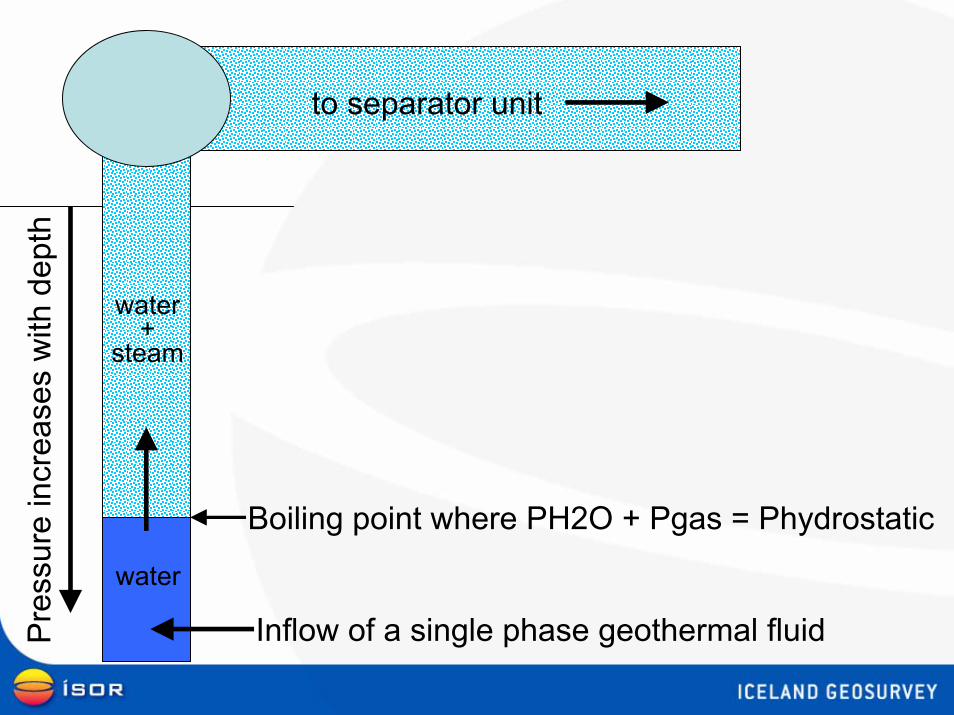
Inflow of a single phase geothermal fluid
water
water+
steam
to separator unit
Boiling point where PH2O + Pgas = Phydrostatic
Pre
ssur
e in
crea
ses
with
dep
th
Inflow of a single phase geothermal fluid
to separator unit
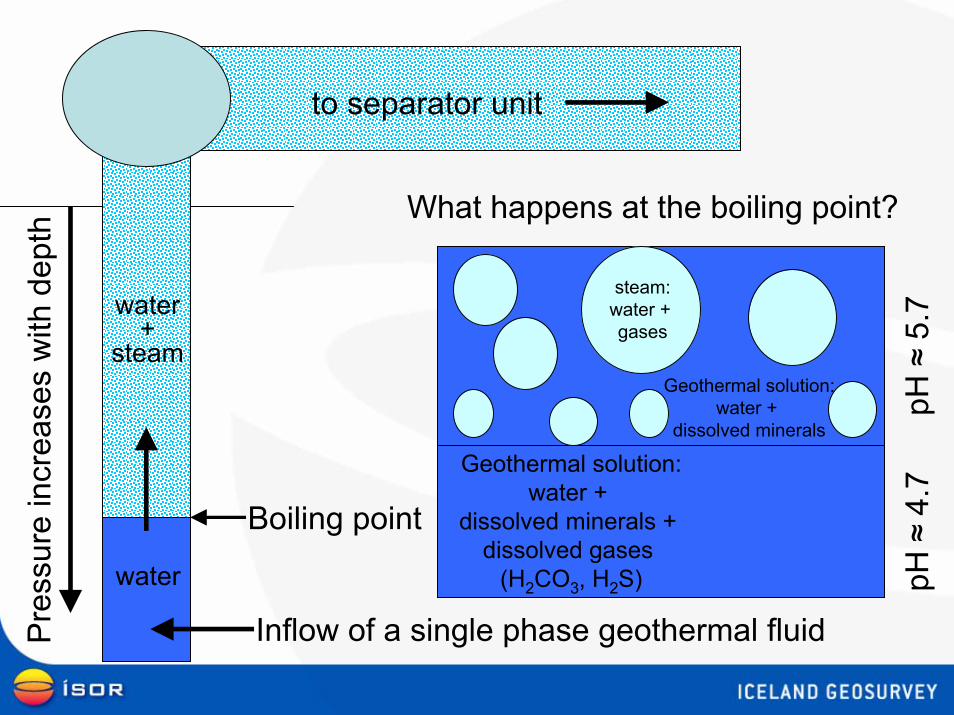
What happens at the boiling point?
Pre
ssur
e in
crea
ses
with
dep
th
water
water+
steam
Geothermal solution:water +
dissolved minerals + dissolved gases
(H2CO3, H2S)
steam:water + gases
Geothermal solution:water +
dissolved minerals
pH ≈
5.7
Boiling point
pH ≈
4.7
Boiling point
water
water+
steam
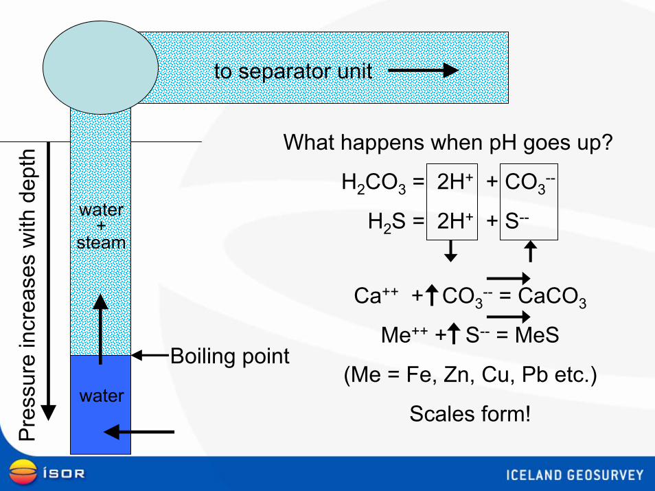
What happens when pH goes up?
H2CO3 = 2H+ + CO3--
H2S = 2H+ + S--
Ca++ + CO3-- = CaCO3
Me++ + S-- = MeS
(Me = Fe, Zn, Cu, Pb etc.)
Scales form!
to separator unit
Pre
ssur
e in
crea
ses
with
dep
th
Boiling point
water
water+
steam
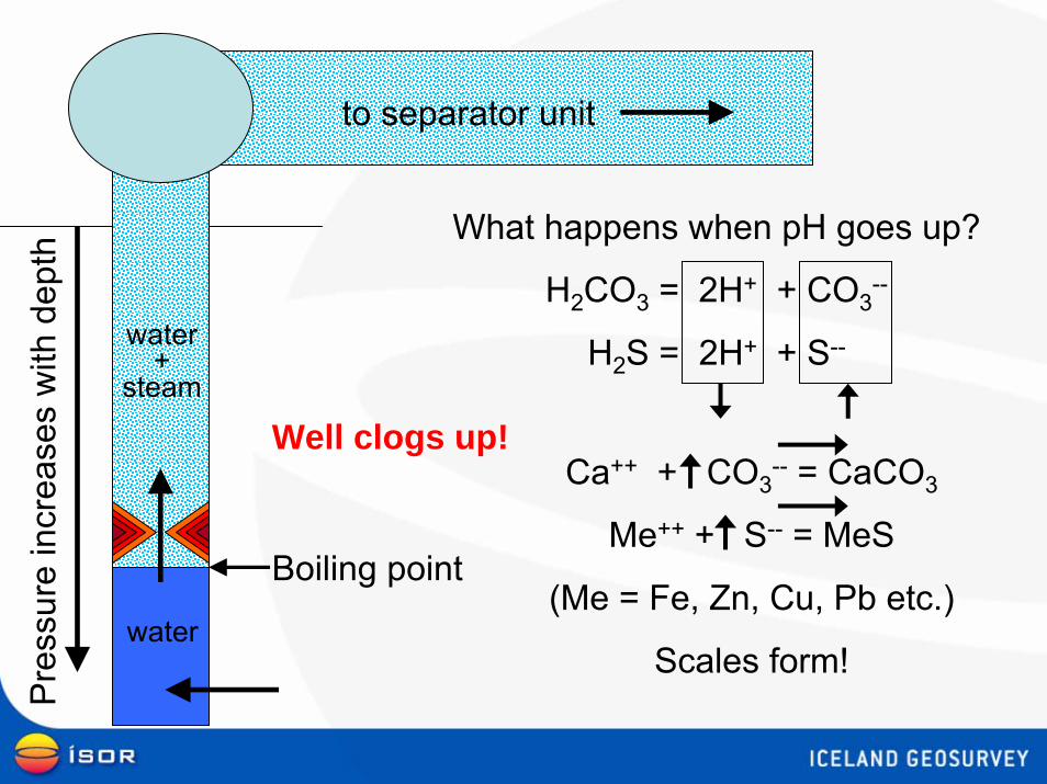
What happens when pH goes up?
H2CO3 = 2H+ + CO3--
H2S = 2H+ + S--
Ca++ + CO3-- = CaCO3
Me++ + S-- = MeS
(Me = Fe, Zn, Cu, Pb etc.)
Scales form!
to separator unit
Well clogs up!
Pre
ssur
e in
crea
ses
with
dep
th
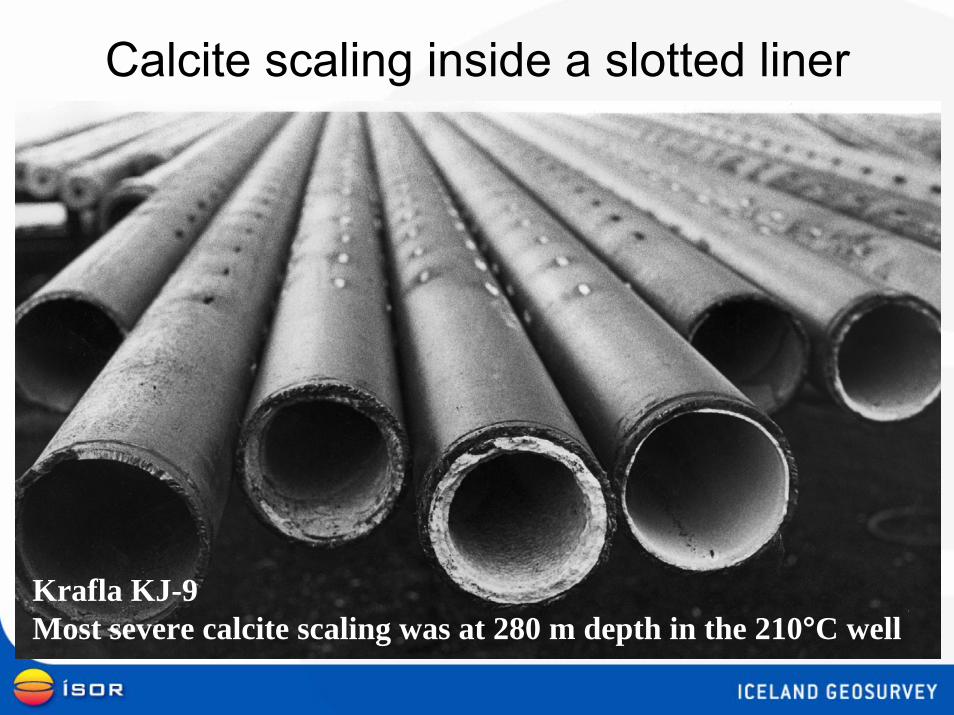
Calcite scaling inside a slotted liner
Krafla KJ-9 Most severe calcite scaling was at 280 m depth in the 210°C well
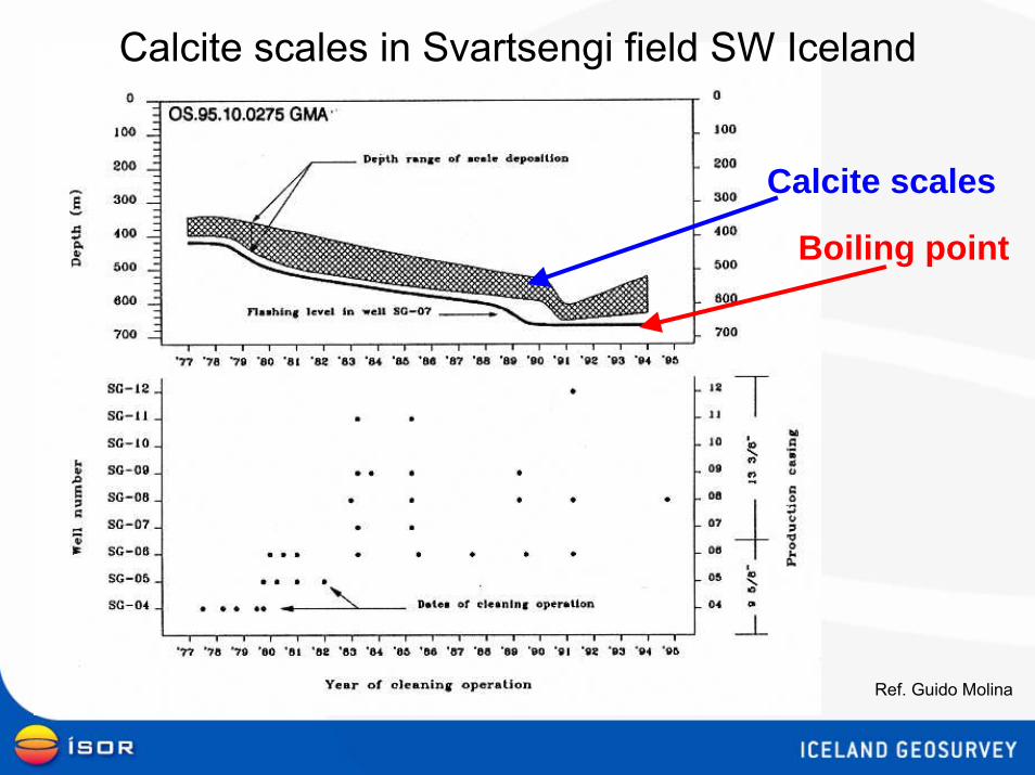
Boiling point
Calcite scales
Calcite scales in Svartsengi field SW Iceland
Ref. Guido Molina
Boiling point
water
water+
steam
to separator unit
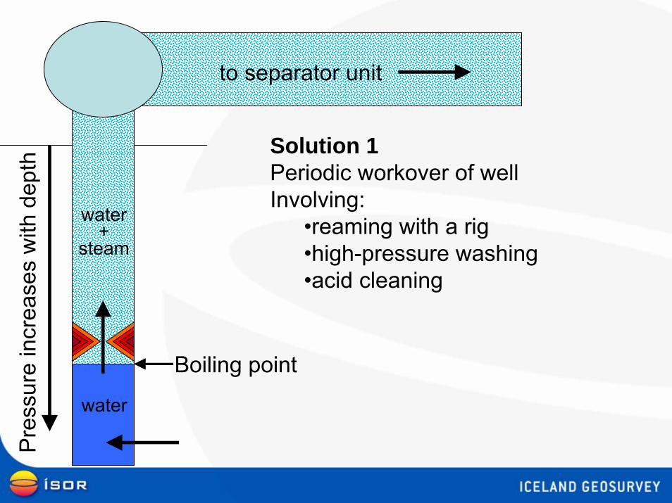
Solution 1Periodic workover of well Involving:
•reaming with a rig•high-pressure washing•acid cleaning
Pre
ssur
e in
crea
ses
with
dep
th
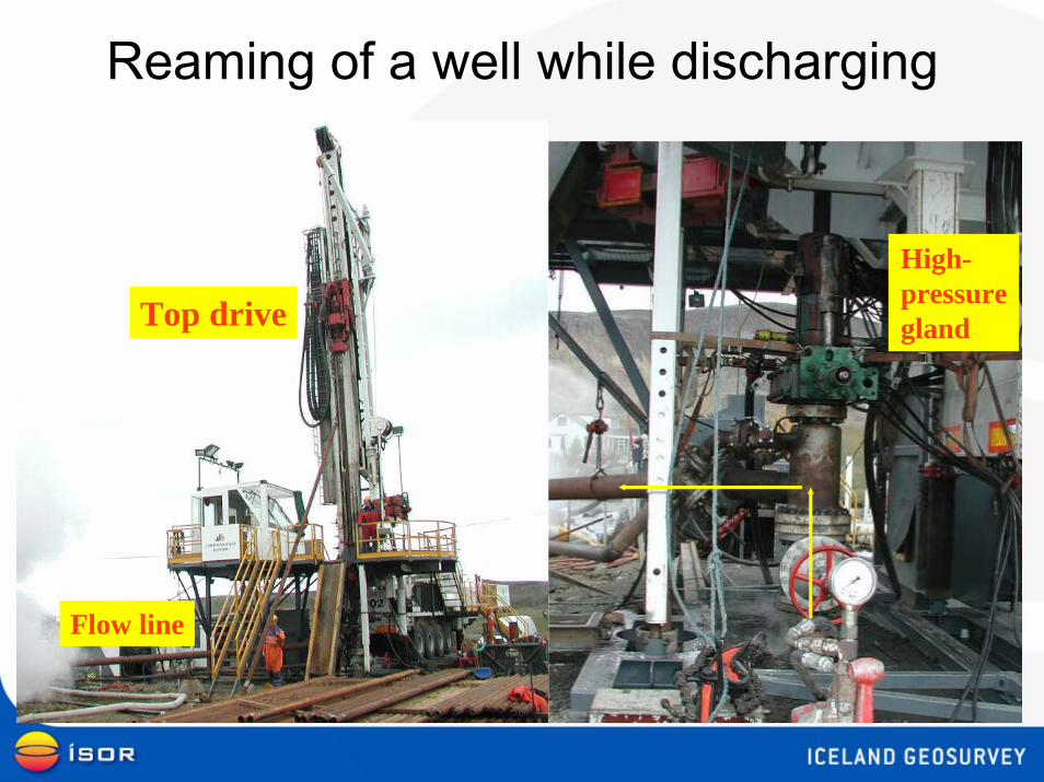
Reaming of a well while discharging
High-pressureglandTop drive
Flow line
water
water+
steam
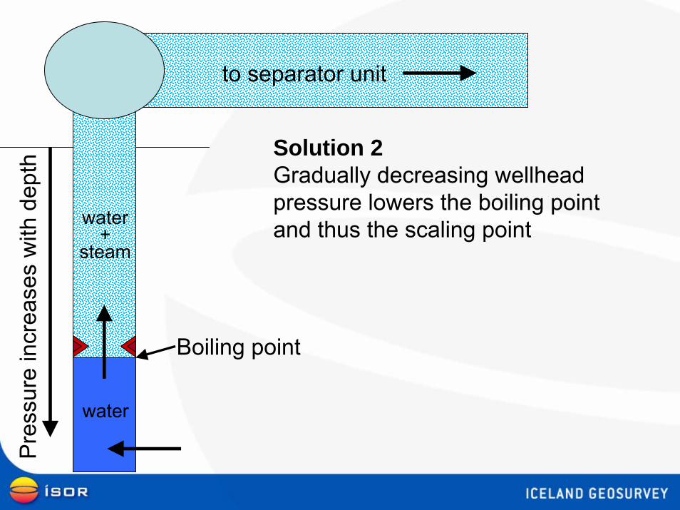
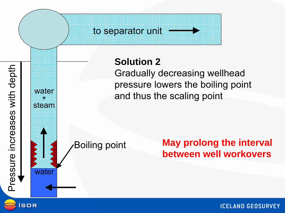
Solution 2Gradually decreasing wellhead pressure lowers the boiling pointand thus the scaling point
to separator unit
Boiling point
Pre
ssur
e in
crea
ses
with
dep
th
Boiling point
water
water+
steam
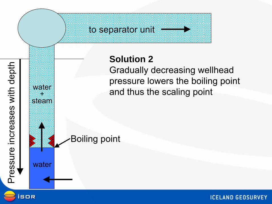
to separator unit
Solution 2Gradually decreasing wellhead pressure lowers the boiling pointand thus the scaling point
Pre
ssur
e in
crea
ses
with
dep
th
Boiling point
water
water+
steam
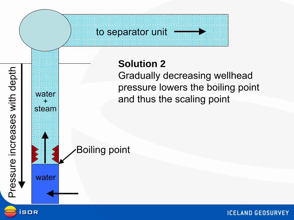
to separator unit
Solution 2Gradually decreasing wellhead pressure lowers the boiling pointand thus the scaling point
Pre
ssur
e in
crea
ses
with
dep
th
Boiling point
water
water+
steam
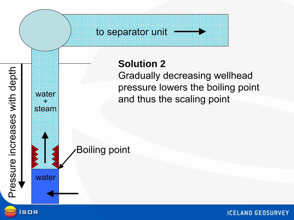
to separator unit
Solution 2Gradually decreasing wellhead pressure lowers the boiling pointand thus the scaling point
Pre
ssur
e in
crea
ses
with
dep
th
Boiling point
water
water+
steam
to separator unit
Solution 2Gradually decreasing wellhead pressure lowers the boiling pointand thus the scaling point
Pre
ssur
e in
crea
ses
with
dep
th
May prolong the intervalbetween well workovers
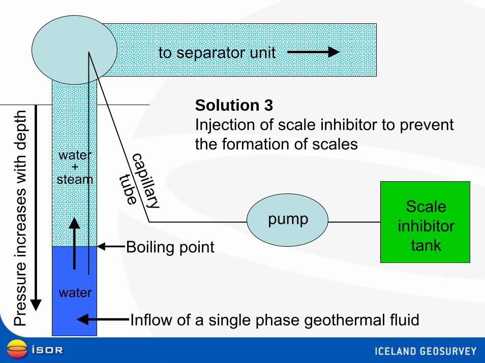
Inflow of a single phase geothermal fluid
Boiling point
water
water+
steam
to separator unit
Solution 3Injection of scale inhibitor to preventthe formation of scales
Scaleinhibitor
tank
capillary
tube
pump
Pre
ssur
e in
crea
ses
with
dep
th
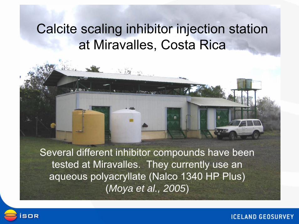
Calcite scaling inhibitor injection stationat Miravalles, Costa Rica
Several different inhibitor compounds have been tested at Miravalles. They currently use an aqueous polyacryllate (Nalco 1340 HP Plus)
(Moya et al., 2005)
Scaling in surface equipment
• Sulfide rich scales• Close to wellheads
• Silica rich scales• Further away from wellheads, common
after separator stations
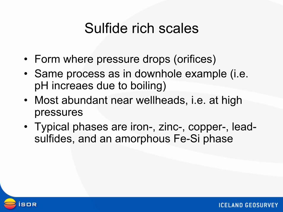
Sulfide rich scales
• Form where pressure drops (orifices)• Same process as in downhole example (i.e.
pH increaes due to boiling)• Most abundant near wellheads, i.e. at high
pressures• Typical phases are iron-, zinc-, copper-, lead-
sulfides, and an amorphous Fe-Si phase
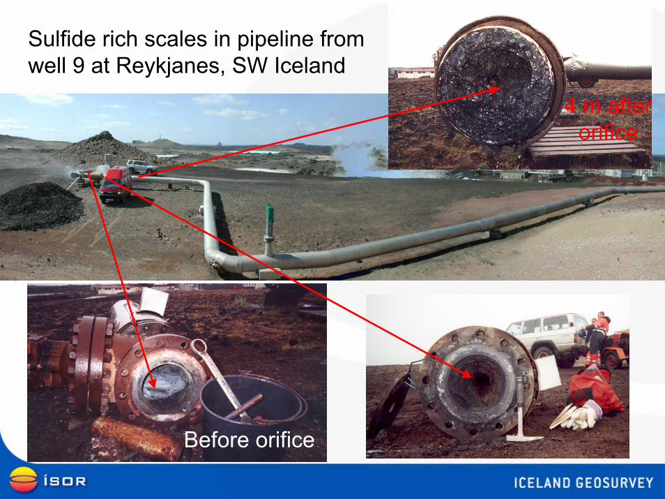
Before orifice
4 m after orifice
Sulfide rich scales in pipeline from well 9 at Reykjanes, SW Iceland
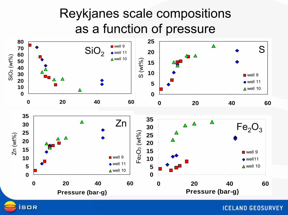
Reykjanes scale compositions as a function of pressure
01020304050607080
0 20 40 60
SiO
2 (w
t%)
well 9well 11well 10
0
5
10
15
20
25
0 20 40 60
S (w
t%)
well 9well 11well 10
05
101520253035
0 20 40 60Pressure (bar-g)
Fe2O
3 (w
t%)
well 9well11well 10
05
101520253035
0 20 40 60Pressure (bar-g)
Zn
(wt%
)
well 9well 11well 10
SiO2
Fe2O3Zn
S
Silica rich scales
• Amorphous silica – not quartz!• Deep fluid saturated with respect to quartz• Boiling increases concentration of dissolved
SiO2• When the fluid reaches saturation with
respect to amorphous silica scales form rapidly and in large quantities
• Problematic in injection wells and surface pipelines, particularly after separator staions
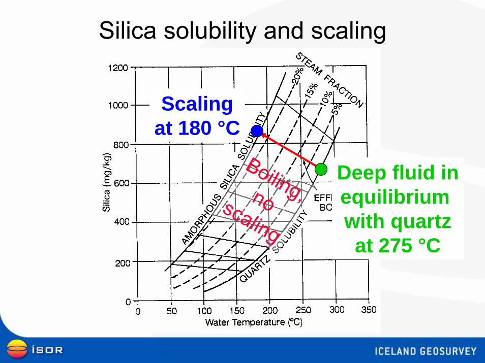
Silica solubility and scaling
Scalingat 180 °C
Boiling,noscaling
Deep fluid inequilibrium with quartzat 275 °C
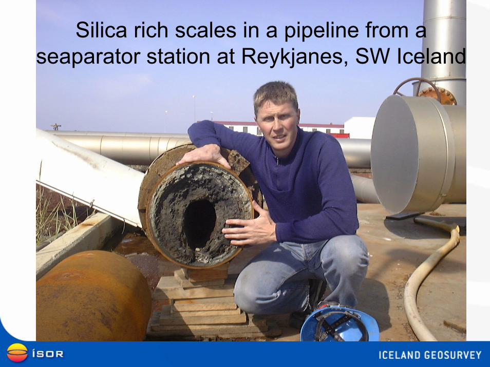
Silica rich scales in a pipeline from a seaparator station at Reykjanes, SW Iceland
Silica rich scales:common solutions to the problem
• Separating steam at high pressure– Wasteful, a lot of thermal energy wasted
• Diluting separated water with condensate– Can cause corrosion
• Acidification– Can cause corrosion
• Crystallize silica in suspension (Crystallizer-Reactor-Clarifies process)– Costly
Corrosion:common problems
• In slotted liners and well casings– In hot systems where deep fluid is acidic and/or saline– H2S can also cause sulfide stress cracking
• At well head: first meter below the cellar floor from outside– Water, oxygen and H2S
• Superheated steam pipelines– First condensate is very acidic, may contain HCl
• Cooling towers and cold condensate pipelines– Condensate is acidic, free carbonic acid very aggressive to steel below
100 °C• Heat exchangers
– Stress corrosion cracking where O2 and Cl- are present at temperatures above 70 °C
• Electronic equipment in power plants– H2S destroys copper wires in electronic devices
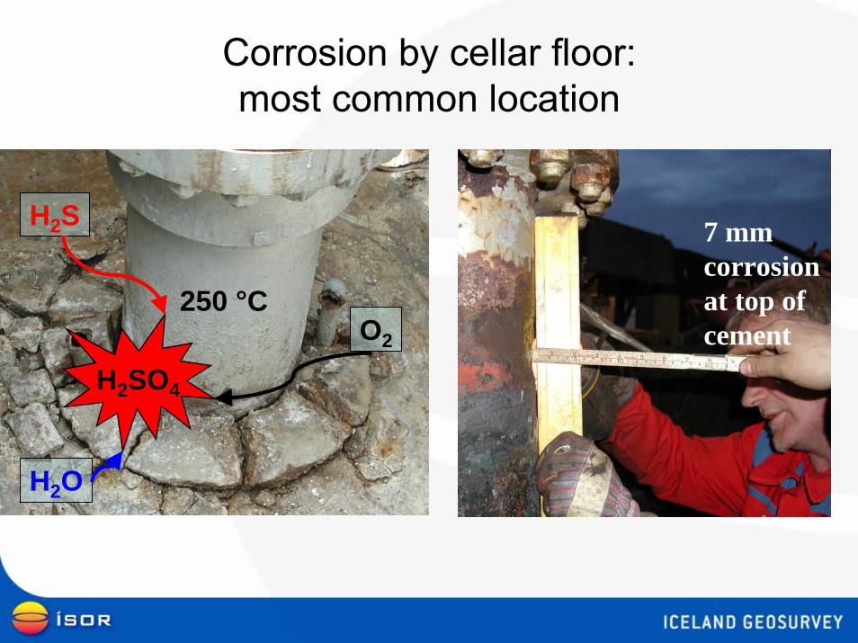
Corrosion by cellar floor:most common location
7 mmcorrosionat top of cement
H2SO4
250 °C
H2S
H2O
O2
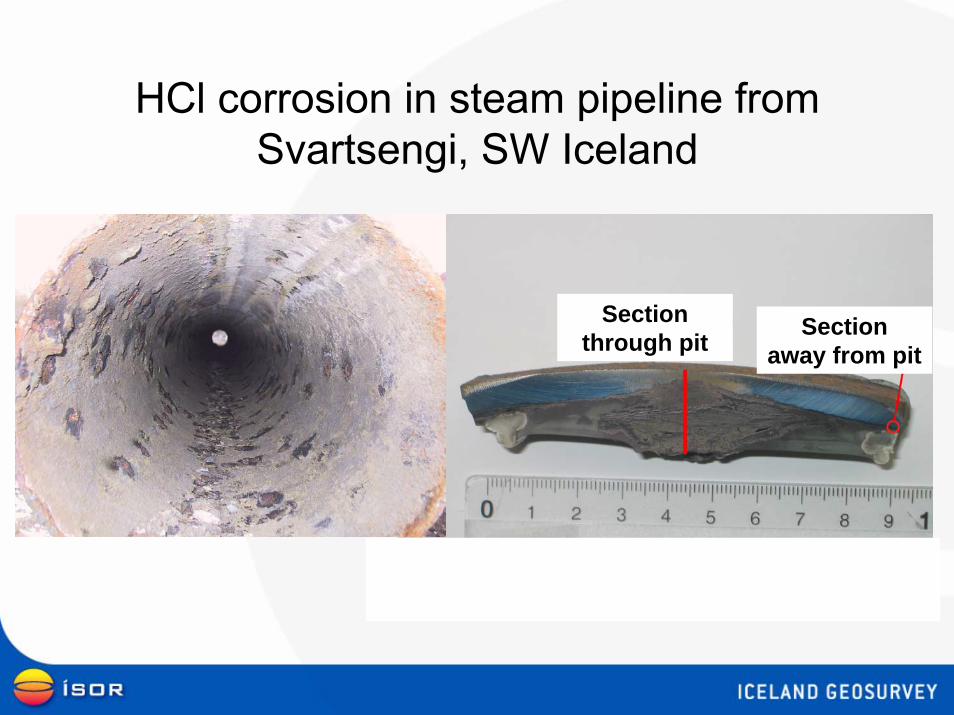
HCl corrosion in steam pipeline from Svartsengi, SW Iceland
Section through pit Section
away from pit
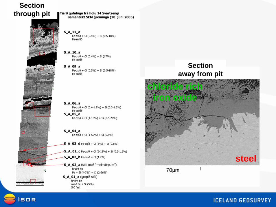
Section through pit
Section away from pit
steel
chloride richiron oxide
Solutions to most corrosion problems:Careful material selection
• Do not use high yield-strength steel for casing and liners (use K-55 or L-80)
• Cr-steel might be needed for the uppermost 100 m of casing
• Use mild steel for steam pipes• Super heated steam pipes should be insulated
and scrubbing might also effectively prevent corrosion in such pipes
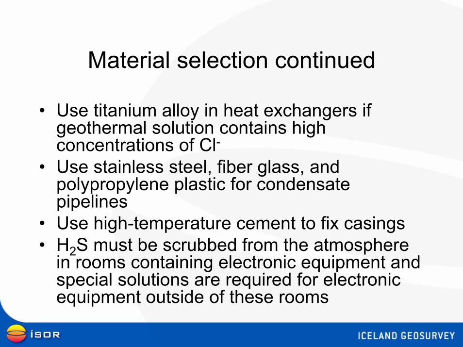
Material selection continued
• Use titanium alloy in heat exchangers if geothermal solution contains high concentrations of Cl-
• Use stainless steel, fiber glass, and polypropylene plastic for condensate pipelines
• Use high-temperature cement to fix casings• H2S must be scrubbed from the atmosphere
in rooms containing electronic equipment and special solutions are required for electronic equipment outside of these rooms
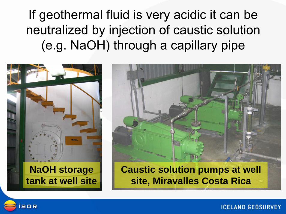
If geothermal fluid is very acidic it can be neutralized by injection of caustic solution
(e.g. NaOH) through a capillary pipe
NaOH storagetank at well site
Caustic solution pumps at well site, Miravalles Costa Rica
Conclusions• Most of the unique problems that have to be dealt with at geothermal
power plants are related to the chemistry of the fluid.• Some of these have resulted in reduced production or a shut-down.• There are proven methods to manage most of these problems but they
will not be overcome completely. Sulfide scaling the most difficult and scaling of reinjection wells.
• The problems will change over time, due the effects of prolongedexploitation of the reservoir.
• Monitoring of the geothermal reservoir and fluid produced is therefore important.
• Effective maintenance procedures have been developed.• Geothermal plants require the services of experts as well as highly
qualified personnel in operation and maintenance.• Geothermal plants can thus be operated–WITHOUT SURPRISES
P.S.
• Select geothermal areas with temperatures in the range 180-290°C.
• For the temperature range 180-240°C beware of calcite scaling, 240-290°C of silica scaling, >290°C of silicate and sulfide scaling.
• In process design “respect” the silica solubility curve.• Avoid reservoirs with high gas or acidic steam.• Use proven equipment and designs.• Monitor the effects of production.


