69
Gesture Controlled UAV Report Ben Schreck and Lee Gross 12/10/2014

Gesture Controlled UAV Report
Ben Schreck and Lee Gross 12/10/2014
Table of Contents 1 Overview (Ben and Lee)
2 Design
2.1 Kinect Camera (Ben)
2.2 Hand Detector (Ben)
2.1.3 USB Adapter (Ben)
2.1.4 Gesture State Machine (Lee)
2.1.4.1 On/Off Gesture
2.1.4.2 Hover
2.1.4.3 Roll
2.1.4.4 Pitch
2.1.5 Digital to Analog Converter (Lee)
2.1.6 Controller (Ben)
2.1.7 Display (Lee)
2.1.8 Initializing the Controller (Ben and Lee)
3 Implementation Process (Ben and Lee)
4 Testing Process (Ben and Lee)
5 Review and Recommendations (Ben and Lee)
6 Conclusion (Ben and Lee)
7 Appendix (Ben and Lee)
1 Overview There are currently two types of unmanned aerial vehicles (UAVs): autonomous aircrafts and remotely piloted aircrafts. Remotely piloted aircrafts are tough to control using handheld remotes. We propose an intuitive approach to controlling these UAVs, using hand gestures rather than remotes. Our project allows a user to control a quadcopter (a type of UAV) using hand gestures. The operator can make these gestures in front of a Microsoft Kinect device, which can sense both colored light and depth of field. Using a Kinect allows us to define more complex gestures that take advantage of the distance of the operator’s hands from the camera. Furthermore, they may allow us to discard the typical colored gloves usually worn by 6.111 students that enable easy hand-tracking by color matching. When an operator makes a correct gesture, the FPGA will classify it, and send the appropriate signal to the quadcopter’s remote controller, which will then send an infrared signal to the quadcopter commanding it to perform a particular action. Due to time constraints, we chose to limit the number of ways the user can control the quadcopter. Manually holding a quadcopter’s altitude constant without complicated controls and avionics is a challenge on its own. Therefore, we decided it is best to only allow the user to turn the quadcopter on and off and control its elevation, as well as turn left or right.
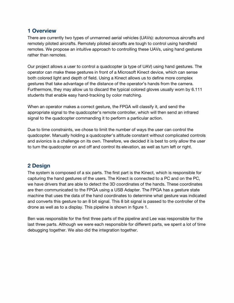
2 Design The system is composed of a six parts. The first part is the Kinect, which is responsible for capturing the hand gestures of the users. The Kinect is connected to a PC and on the PC, we have drivers that are able to detect the 3D coordinates of the hands. These coordinates are then communicated to the FPGA using a USB Adapter. The FPGA has a gesture state machine that uses the data of the hand coordinates to determine what gesture was indicated and converts this gesture to an 8 bit signal. This 8 bit signal is passed to the controller of the drone as well as to a display. This pipeline is shown in figure 1. Ben was responsible for the first three parts of the pipeline and Lee was responsible for the last three parts. Although we were each responsible for different parts, we spent a lot of time debugging together. We also did the integration together.
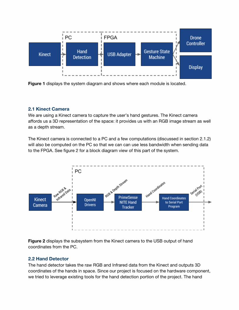
Figure 1 displays the system diagram and shows where each module is located.
2.1 Kinect Camera We are using a Kinect camera to capture the user’s hand gestures. The Kinect camera affords us a 3D representation of the space: it provides us with an RGB image stream as well as a depth stream. The Kinect camera is connected to a PC and a few computations (discussed in section 2.1.2) will also be computed on the PC so that we can can use less bandwidth when sending data to the FPGA. See figure 2 for a block diagram view of this part of the system.
Figure 2 displays the subsystem from the Kinect camera to the USB output of hand coordinates from the PC. 2.2 Hand Detector The hand detector takes the raw RGB and Infrared data from the Kinect and outputs 3D coordinates of the hands in space. Since our project is focused on the hardware component, we tried to leverage existing tools for the hand detection portion of the project. The hand
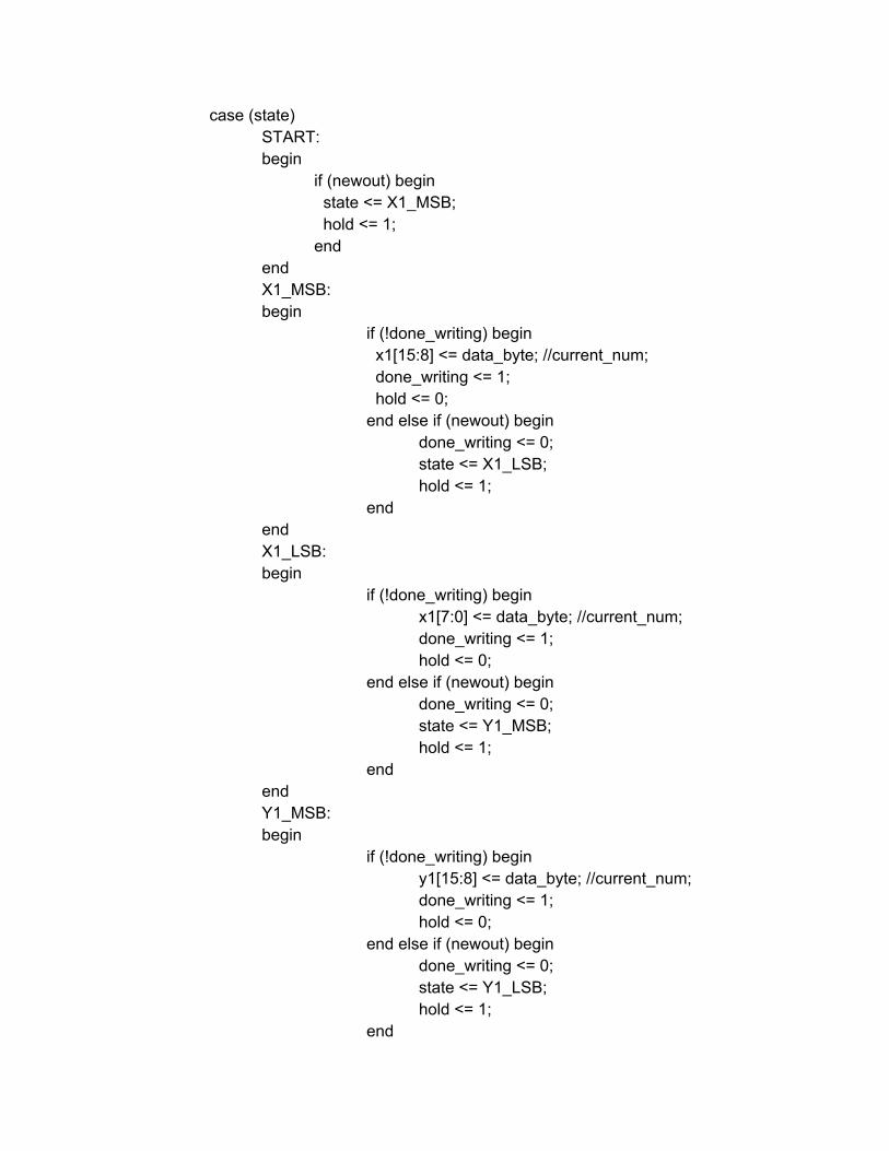
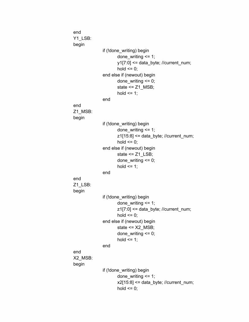
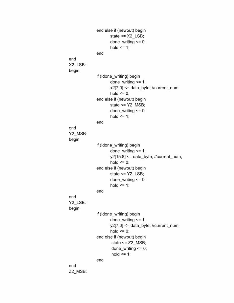
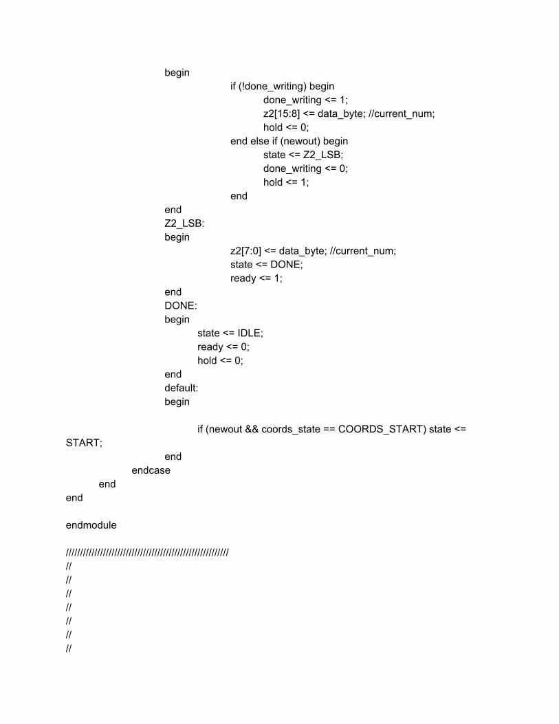
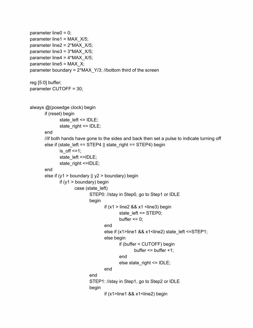
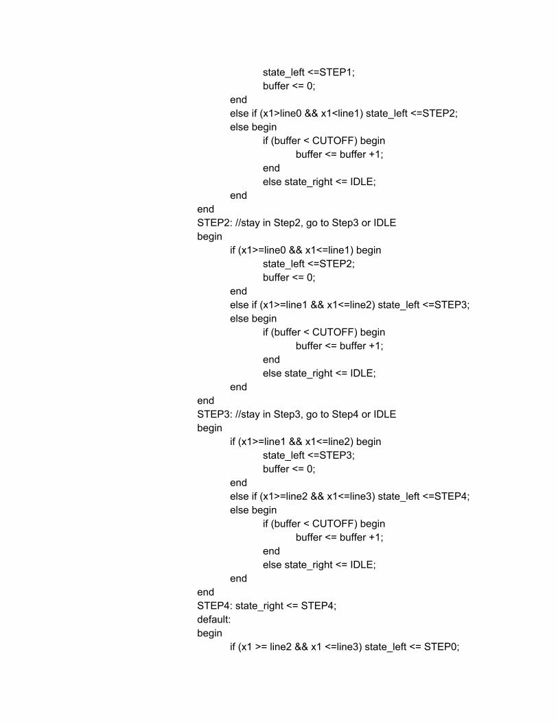
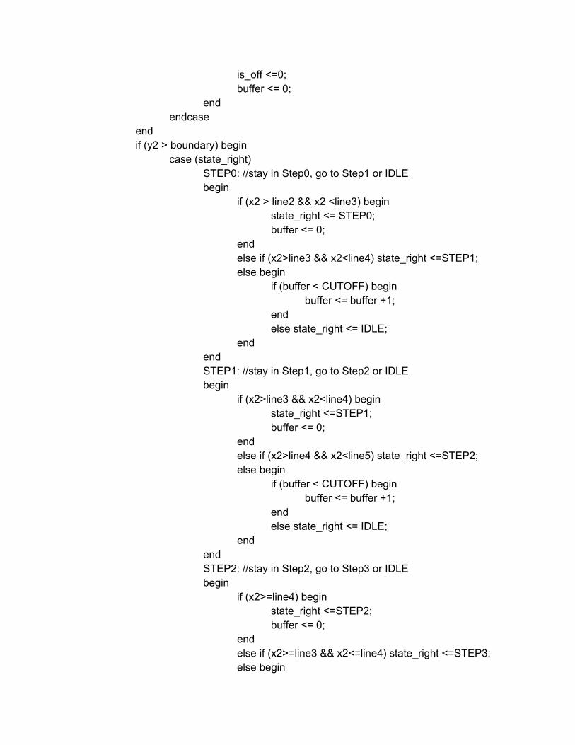
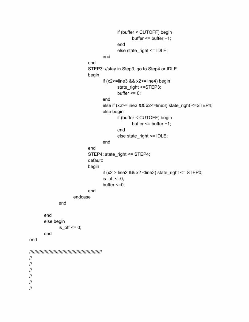
detector is composed of open source libraries (OpenNI Drivers) that are able to interpret the raw input streams from the Kinect. Once these raw input streams are interpreted, we use an open source hand tracker algorithm to output the hand coordinates. The only part that we implemented ourselves is software that sends the hand coordinates data to a serial port. A detailed diagram of the hand detector component is shown in figure 2. When we send data to the serial port, we send an entire 13-byte hand coordinate. In doing so, we speed up the throughput of the USB-to-FIFO chip. It operates much faster when data is sent in chunks up to 128 bytes, the size of its internal buffer. 2.1.3 USB Adapter This module is located on the FPGA and it receives data from the kinect-connected PC. There are two layers. The first is a low-level module taken from the course website that translates 8-bit data from the USB-to-FIFO chip into usable form on the FPGA. On top of that, we built a module that parses the 8-bit data into a set of 13 byte hand coordinates that get saved into special purpose registers on the FPGA. The key feature of this module is the encoding of a “start” symbol to mark where hand coordinates begin. The PC serializes hand coordinate data into a set of 13 8-bit values, all encoded in ASCII. The first symbol corresponds to the “S” ASCII character. When the FPGA sees this symbol, it begins saving a new hand coordinate. The next character it reads corresponds to the higher-order bits of the first 16-bit x-coordinate corresponding to a particular hand. The subsequent character corresponds to the lower-order bits of this coordinate,the next character corresponds to the higher-order bits of the first y-coordinate, and so on. In total, we send 6 16-bit integers: x1, y1, z1, x2, y2, z2. The verilog code for this state machine is shown in the appendix. 2.1.4 Gesture State Machine The gesture state machine is responsible for converting 3D coordinates of two hands in space into 8 bit signals. The state machine has two states: on or off. When the state machine is off, no signals get sent to the controller. When the state machine is on, we send three different signals: hover, pitch and roll (corresponding to the different degrees of freedom with which we can control the quadcopter). We also indicate a “dead zone” for the user’s convenience. If any of the hands is in the dead zone, no signal is sent to the controller. 2.1.4.1 On/Off Gesture To turn the the drone on and off, we have a simple state machine that looks for the hands to follow a particular pattern. If the hands follow that pattern, we invert the state (if the state was on, then turn it off and if it was off, turn it on). The pattern we were looking for is shown in figure 3. It looks at the right hand and checks if it went from the center to the right most square and then back to the center. It also checks if the left hand started in the center and then went to the left most block and then returned to the center. If either of the hands is able to complete the gesture, it signals the system to invert the on-state.
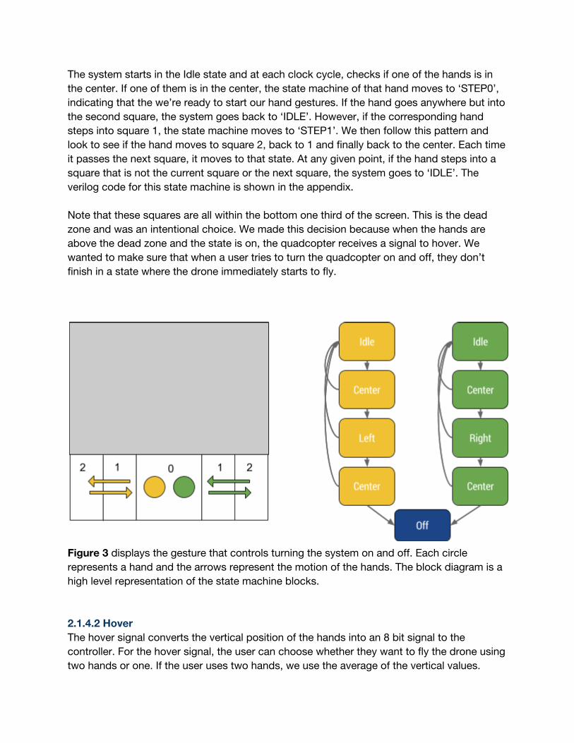
The system starts in the Idle state and at each clock cycle, checks if one of the hands is in the center. If one of them is in the center, the state machine of that hand moves to ‘STEP0’, indicating that the we’re ready to start our hand gestures. If the hand goes anywhere but into the second square, the system goes back to ‘IDLE’. However, if the corresponding hand steps into square 1, the state machine moves to ‘STEP1’. We then follow this pattern and look to see if the hand moves to square 2, back to 1 and finally back to the center. Each time it passes the next square, it moves to that state. At any given point, if the hand steps into a square that is not the current square or the next square, the system goes to ‘IDLE’. The verilog code for this state machine is shown in the appendix. Note that these squares are all within the bottom one third of the screen. This is the dead zone and was an intentional choice. We made this decision because when the hands are above the dead zone and the state is on, the quadcopter receives a signal to hover. We wanted to make sure that when a user tries to turn the quadcopter on and off, they don’t finish in a state where the drone immediately starts to fly.
Figure 3 displays the gesture that controls turning the system on and off. Each circle represents a hand and the arrows represent the motion of the hands. The block diagram is a high level representation of the state machine blocks. 2.1.4.2 Hover The hover signal converts the vertical position of the hands into an 8 bit signal to the controller. For the hover signal, the user can choose whether they want to fly the drone using two hands or one. If the user uses two hands, we use the average of the vertical values.
Alternatively, if the user only uses one of the hands, we only consider the vertical value of the hand that is displayed on the screen. If the state is off or if either of the hands is in the bottom one third of the screen, we don’t send a signal. If the average of the hands is in the top two thirds of the screen, we send a signal between 0% to 45%. 0% means that the drone is not hovering and 45% is 45% of the max propeller spin rate, translating into slower vertical acceleration than 100%. We capped the maximum height at 45% for usability reasons. Any higher speed crashed the drone into the ceiling. A 45% signal is converted to a digital value of 116 (out of 256) to be output from this module. The signal sent is explained further in section 2.1.4.5. 2.1.4.3 Roll The roll signal converts the vertical position of the hands into an 8 bit signal to the controller. The roll signal requires both hands to be on the screen and takes the difference between their vertical values. If the left hand is above the right hand, the drone will fly right. If the right hand is above the left hand, the drone will fly left. We allow the user some wiggle room and instruct the drone to stay in place if the difference between the hands is below some threshold. If the difference is above the threshold, we signal the drone to either move left or right. Specifically, we send values ranging between 0 to 256 where 128 corresponds to staying in place, anything below 128 corresponds to moving to the left and anything above 128 corresponds to moving to the right. 2.1.4.4 Pitch The pitch signal converts the depth position of the hands into an 8 bit signal to the controller indicating if the drone should fly forward, back or remain in place. Just like the hover signal, we average both pitch values of the hands and use that as our signal. Unlike the roll and hover signals, the pitch signal is computed with buckets. We predefined three buckets, the forward bucket, the center bucket and the back bucket, corresponding to how far away in space the hands are from the Kinect camera. We send a signal corresponding to the bucket in which the average value of the hands fall. So if the average value is in the forward bucket, we send a value of 192, if the average value is in the back bucket, we send a value of 64, and if the average value is in the center bucket, we send a value of 128 (128 is no forward/backward pitch because it’s half of the max value of 256). We chose to use the bucket method and not send a gradual increase in the forward/backwards signal because it provided a better user experience. 2.1.5 Digital to Analog Converter The digital to analog converter (DAC) takes an 8 bit value and converts it into an analog signal that we send to the controller of the drone. The 8 bit value it takes as an input represent a fraction where the denominator is 256 and the numerator is the 8 bit input value. This fraction corresponds to the percent of the max voltage value we want to pass to the quadcopter controller. We pass the DAC a reference voltage of 3.3V so the 8 bit value we
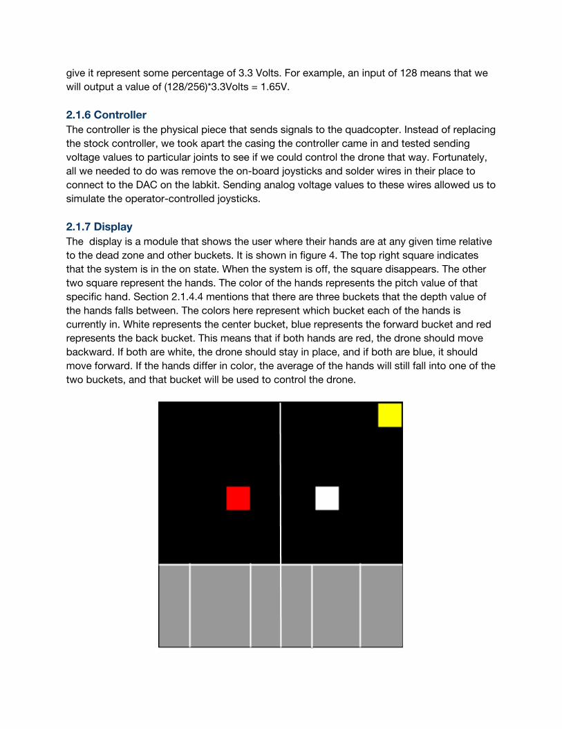
give it represent some percentage of 3.3 Volts. For example, an input of 128 means that we will output a value of (128/256)*3.3Volts = 1.65V. 2.1.6 Controller The controller is the physical piece that sends signals to the quadcopter. Instead of replacing the stock controller, we took apart the casing the controller came in and tested sending voltage values to particular joints to see if we could control the drone that way. Fortunately, all we needed to do was remove the on-board joysticks and solder wires in their place to connect to the DAC on the labkit. Sending analog voltage values to these wires allowed us to simulate the operator-controlled joysticks. 2.1.7 Display The display is a module that shows the user where their hands are at any given time relative to the dead zone and other buckets. It is shown in figure 4. The top right square indicates that the system is in the on state. When the system is off, the square disappears. The other two square represent the hands. The color of the hands represents the pitch value of that specific hand. Section 2.1.4.4 mentions that there are three buckets that the depth value of the hands falls between. The colors here represent which bucket each of the hands is currently in. White represents the center bucket, blue represents the forward bucket and red represents the back bucket. This means that if both hands are red, the drone should move backward. If both are white, the drone should stay in place, and if both are blue, it should move forward. If the hands differ in color, the average of the hands will still fall into one of the two buckets, and that bucket will be used to control the drone.

Figure 4 shows the display. The red and white squares show the hands. Red indicates that the left hand is in the backward bucket (for pitch) and the white hand indicates that the right hand is in the center bucket. The yellow square at the top of the screen indicates that we are in the on state. 2.1.8 Initializing the controller We included a module that sent signals to the control unit to initialize it. When the controller is powered on, it does not immediately start sending signals to the quadcopter. Instead, the operator has to power the throttle (“hover”) to 100% and back to 0% before it starts sending any signals. Our module sends a pulse of 100% when it is initially programmed or reset on the lab kit, in order to initialize the remote.
3 Implementation Process
Figure 5 shows the project in action. We started out implementing the two end-components first: the kinect/hand recognition and the controller of the drone. We chose to do this because those were the riskiest parts of the
project and determined the scope of the remaining modules. We were able to interface with both of these without too much trouble. Next Ben worked on the USB Adapter module and Lee worked on the gesture state machine. We then tested each component individually and then tried to integrate the USB Adapter with the Hand Location module. Because of the complexity of integration, we worked on it together. This part of our project took was one of the hardest parts because it was the least transparent. It was tough to debug and to see what was actually going on, since there were so many independent interacting components. Every piece had to sync up with every other piece. The moment we received hand coordinates on the FPGA’s hex display we were confident that the rest of the project would be possible. Once we integrated the first three components, we tried to integrate it with the hand gestures state machine but that proved to be difficult. In order to have a more accurate representation of what was happening, we first built the display module so that we could debug the gesture state machine more easily. This enabled us to visually see where the FPGA thought the hand coordinates were, to determine what state it was in. Finally, when we were able to integrate all the pieces, we tested our system by flying the drone. At that point, we made a couple of user interaction changes. We made our system more strict in terms of when it was sending hover signals to the controller. We wanted to make sure that if a user is distracted or is trying to stop, any time he has one of his hands below the deadzone line, the drone will not fly. There were a few pieces we wanted to include but did not end up getting to work effectively due to time constraints. These attempted modules are detailed below. 3.1 Additional Display Components Lee attempted to show small level meters in the corner of the display that would indicate what values are currently being sent to the drone control unit. Nothing stopped us from implementing this besides time. A mockup is show below in figure 6.
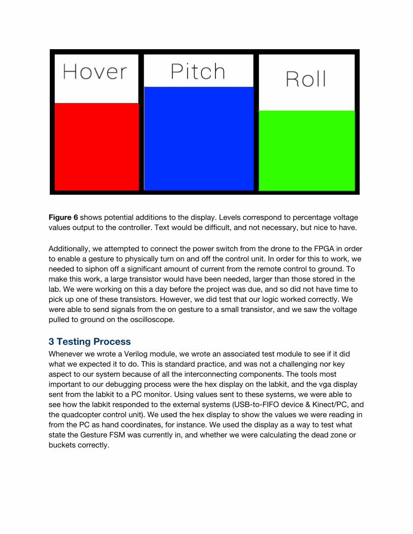
Figure 6 shows potential additions to the display. Levels correspond to percentage voltage values output to the controller. Text would be difficult, and not necessary, but nice to have. Additionally, we attempted to connect the power switch from the drone to the FPGA in order to enable a gesture to physically turn on and off the control unit. In order for this to work, we needed to siphon off a significant amount of current from the remote control to ground. To make this work, a large transistor would have been needed, larger than those stored in the lab. We were working on this a day before the project was due, and so did not have time to pick up one of these transistors. However, we did test that our logic worked correctly. We were able to send signals from the on gesture to a small transistor, and we saw the voltage pulled to ground on the oscilloscope.
3 Testing Process Whenever we wrote a Verilog module, we wrote an associated test module to see if it did what we expected it to do. This is standard practice, and was not a challenging nor key aspect to our system because of all the interconnecting components. The tools most important to our debugging process were the hex display on the labkit, and the vga display sent from the labkit to a PC monitor. Using values sent to these systems, we were able to see how the labkit responded to the external systems (USB-to-FIFO device & Kinect/PC, and the quadcopter control unit). We used the hex display to show the values we were reading in from the PC as hand coordinates, for instance. We used the display as a way to test what state the Gesture FSM was currently in, and whether we were calculating the dead zone or buckets correctly.
Our project was fortunate too in that the output of the system was physical, and we could tell whether it worked based on whether the quadcopter was actually flying correctly. One way to debug was to actually attempt to fly the machine.
5 Review and Recommendations
The hardest parts for us to debug were the interconnects of the system. We dealt with many different digital systems that all had to work together, and even though we thought that connecting them together could prove challenging, we still underestimated how much work it actually involved. If we were to do it again, we might allocate more time to these critical sections. Additionally, we purchased a cheap plastic quadcopter, which served its purpose and allowed us to crash it many times without much consequence. However, its quality severely limited our ability to control and fly it. Storing in the lab lockers warped it more and more throughout the project, which caused it to veer to different directions in flight. Furthermore, it had almost no onboard stabilization mechanism, making it harder still to control. If we continue this project, a first step will be to use a higher quality quadcopter. One amazing property we found is that the weakest link of the whole system is the open source software on the PC that tracks the operator’s hands. We used this software unmodified, and it did a particularly poor job at recognizing multiple hands at once. Hands were constantly being erroneously dropped, and very regularly the tracking mechanism would glitch and track different parts of the body. We thought of two solutions to improve this aspect of the system. The first is to try to upgrade to the newest Kinect model, which provides a much more accurate depth image. We assume tracking hands would be much easier with this upgraded sensor. The other would be to do away with cameras and instead wear a tracking wrist band, which sends signals wirelessly to the PC or even straight to the FPGA. These would send a much more constant stream of data, and would enable better precision flight.
6 Conclusion
The system as a unit works consistently now, and we achieved our goal of controlling a quadcopter using gestures. We implemented four gestures. One gesture turns on and off the quadcopter, and the other three send control signals instructing it how to fly. None of the potential risks we identified early on were too large to overcome. However, the quality and precision of flight were less ideal than anticipated. Because the open source software we used to track hands was not as accurate as we expected, we could never pilot the aircraft for more than 30 seconds at one time. This could have been
increased by simply flying the craft outside instead of in the cramped lab environment, but still reflects a less-than-ideal hand tracking system. An incredible success though, was the level of intuitiveness of the system. When we initially bought the quadcopter, we experimented by flying it with the remote control provided. This was a difficult task, and neither of us were able to fly it very well, even after spending a good hour or so attempting to learn. In the new system we built, we invited a friend to test it out. He had no prior experience with quadcopter, and was immediately able to fly it better than we were able to, with only the simplest of instructions. While this does not constitute a scientifically significant study, it does suggest that the potential value of switching to gesture-based control for quadcopter pilots is significant, and may make piloting these crafts much easier to learn.
7 Appendix 7.1 Glossary Quadcopter: unmanned aircraft that achieves flight using 4 symmetric rotors Quadcopter controller: the system that sends radio-frequency signals to the quadcopter instructing it to fly a particular way with a particular intensity Kinect: hardware device made by Microsoft that uses both standard and infrared cameras to sense both color images as well as distance from the camera. FPGA: field programmable gate array. Hardware device that can emulate any other hardware device within certain bounds set by internal memory limits. Hand Detector: open-source software program running on a PC that finds and tracks the location of a user’s hands in space. This program is part of the NITE open-source library, which uses OpenNI. OpenNI: open-source software program used in the Hand Detector Hover: term describing how fast the quadcopter spins its rotors, which translates into vertical acceleration Roll: term describing sideways motion of the quadcopter Pitch: term describing forward/backward motion of the quadcopter

7.2 Code /////////////////////////////////Software (on PC, extension to PrimeSense OpenNI/NITE open source library) ///////////////////////////////// https://github.com/OpenNI/OpenNI ///////////////////////////////// //////Main.cpp additions char portname[] = "/dev/cu.usbserialDPE0AJZN"; int fd = initializeSerialPort(portname); //////////// //////PointDrawer.cpp additions std::map<XnUInt32, std::list<XnPoint3D> >::const_iterator PointIterator; std::list<XnPoint3D>::const_iterator PositionIterator; // Find first 2 hands // first hand PointIterator = m_History.begin(); PositionIterator = PointIterator>second.begin(); XnPoint3D ptl(*PositionIterator); HandCoordinates hand; hand.left_x= int(ptl.X); hand.left_y=int(ptl.Y); hand.left_z=int(ptl.Z); //second hand if (++PointIterator != m_History.end()) PositionIterator = PointIterator>second.begin(); XnPoint3D ptr(*PositionIterator); hand.right_x= int(ptr.X); hand.right_y=int(ptr.Y); hand.right_z=int(ptr.Z); else hand.right_x= 0; hand.right_y= 0; hand.right_z= 0; serialize(&hand, ((char*)&out_coords)+out_coords_index); out_coords_index += sizeof(SerialHandCoordinates); if (out_coords_index == sizeof(SerialHandCoordinates)*HAND_COORD_BUF_SIZE) int n = write (fd, out_coords, sizeof(out_coords));
if (n < 0) fputs("write() of hand coords failed!\n", stderr); out_coords_index = 0; /////////// //////////SerialWrite.h//// typedef struct uint16_t left_x; uint16_t left_y; uint16_t left_z; uint16_t right_x; uint16_t right_y; uint16_t right_z; HandCoordinates; typedef char SerialHandCoordinates[sizeof(uint16_t)*6+1]; //tets void serialize(HandCoordinates* hc, SerialHandCoordinates serial_hc); int initializeSerialPort(char *portname); /////////////// //////////SerialWrite.cpp//// #include "SerialWrite.h" void serialize(HandCoordinates* hc, char *q) *q = 'S'; q++; *q = *(((char*)&(hc>left_x))+1); q++; *q = *((char*) &(hc>left_x)); q++; *q = *(((char*)&(hc>left_y))+1); q++; *q = *((char*) &(hc>left_y)); q++; *q = *(((char*)&(hc>left_z))+1); q++; *q = *((char*) &(hc>left_z)); q++; *q = *(((char*)&(hc>right_x))+1); q++; *q = *((char*) &(hc>right_x)); q++; *q = *(((char*)&(hc>right_y))+1); q++; *q = *((char*) &(hc>right_y)); q++; *q = *(((char*)&(hc>right_z))+1); q++;
*q = *((char*) &(hc>right_z)); q++; ; int set_interface_attribs (int fd, int speed, int parity) struct termios tty; memset (&tty, 0, sizeof tty); if (tcgetattr (fd, &tty) != 0) printf("error %d from tcgetattr", errno); return 1; cfsetospeed (&tty, speed); cfsetispeed (&tty, speed); tty.c_cflag = (tty.c_cflag & ~CSIZE) | CS8; // 8bit chars // disable IGNBRK for mismatched speed tests; otherwise receive break // as \000 chars //tty.c_iflag &= ~IGNBRK; // disable break processing tty.c_iflag &= IGNBRK; // disable break processing tty.c_lflag = 0; // no signaling chars, no echo, // no canonical processing tty.c_oflag = 0; // no remapping, no delays tty.c_cc[VMIN] = 0; // read doesn't block tty.c_cc[VTIME] = 5; // 0.5 seconds read timeout tty.c_iflag &= ~(IXON | IXOFF | IXANY); // shut off xon/xoff ctrl tty.c_cflag |= (CLOCAL | CREAD);// ignore modem controls, // enable reading tty.c_cflag &= ~(PARENB | PARODD); // shut off parity tty.c_cflag |= parity; tty.c_cflag &= ~CSTOPB; tty.c_cflag &= ~CRTSCTS; if (tcsetattr (fd, TCSANOW, &tty) != 0) printf("error %d from tcsetattr", errno); return 1;
return 0; void set_blocking (int fd, int should_block) struct termios tty; memset (&tty, 0, sizeof tty); if (tcgetattr (fd, &tty) != 0) printf("error %d from tggetattr", errno); return; tty.c_cc[VMIN] = should_block ? 1 : 0; tty.c_cc[VTIME] = 5; // 0.5 seconds read timeout if (tcsetattr (fd, TCSANOW, &tty) != 0) printf("error %d setting term attributes", errno); enum kNumRetries = 3 ; int initializeSerialPort(char *portname) int fd = open (portname, O_RDWR | O_NOCTTY | O_SYNC); printf("FD OPEN, fd = %d", fd); if (fd < 0) printf("error %d opening %s: %s", errno, portname, strerror (errno)); return 1; set_interface_attribs (fd, B9600, 0); // set speed to 115,200 bps, 8n1 (no parity) set_blocking (fd, 0); // set no blocking return fd; ///////////////////
/////////////////////////////////Hardware Description Language Code ////////////////////GestureControlled Drone Verilog//////////////////////// // // // // // // // // ////////////////////Labkit.v//////////////////////// /////////////////////////////////////////////////////////////////////////////// // // 6.111 FPGA Labkit Template Toplevel Module // // For Labkit Revision 004 // // // Created: October 31, 2004, from revision 003 file // Author: Nathan Ickes // /////////////////////////////////////////////////////////////////////////////// // // CHANGES FOR BOARD REVISION 004 // // 1) Added signals for logic analyzer pods 24. // 2) Expanded "tv_in_ycrcb" to 20 bits. // 3) Renamed "tv_out_data" to "tv_out_i2c_data" and "tv_out_sclk" to // "tv_out_i2c_clock". // 4) Reversed disp_data_in and disp_data_out signals, so that "out" is an // output of the FPGA, and "in" is an input. // // CHANGES FOR BOARD REVISION 003 // // 1) Combined flash chip enables into a single signal, flash_ce_b. //
// CHANGES FOR BOARD REVISION 002 // // 1) Added SRAM clock feedback path input and output // 2) Renamed "mousedata" to "mouse_data" // 3) Renamed some ZBT memory signals. Parity bits are now incorporated into // the data bus, and the byte write enables have been combined into the // 4bit ram#_bwe_b bus. // 4) Removed the "systemace_clock" net, since the SystemACE clock is now // hardwired on the PCB to the oscillator. // /////////////////////////////////////////////////////////////////////////////// // // Complete change history (including bug fixes) // // 2006Mar08: Corrected default assignments to "vga_out_red", "vga_out_green" // and "vga_out_blue". (Was 10'h0, now 8'h0.) // // 2005Sep09: Added missing default assignments to "ac97_sdata_out", // "disp_data_out", "analyzer[23]_clock" and // "analyzer[23]_data". // // 2005Jan23: Reduced flash address bus to 24 bits, to match 128Mb devices // actually populated on the boards. (The boards support up to // 256Mb devices, with 25 address lines.) // // 2004Oct31: Adapted to new revision 004 board. // // 2004May01: Changed "disp_data_in" to be an output, and gave it a default // value. (Previous versions of this file declared this port to // be an input.) // // 2004Apr29: Reduced SRAM address busses to 19 bits, to match 18Mb devices // actually populated on the boards. (The boards support up to // 72Mb devices, with 21 address lines.) // // 2004Apr29: Change history started // /////////////////////////////////////////////////////////////////////////////// module labkit (beep, audio_reset_b, ac97_sdata_out, ac97_sdata_in, ac97_synch, ac97_bit_clock, vga_out_red, vga_out_green, vga_out_blue, vga_out_sync_b,
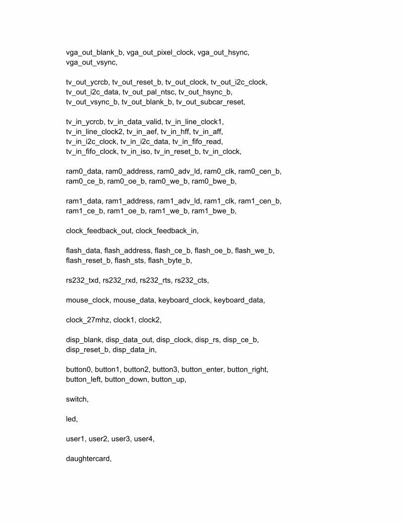
vga_out_blank_b, vga_out_pixel_clock, vga_out_hsync, vga_out_vsync, tv_out_ycrcb, tv_out_reset_b, tv_out_clock, tv_out_i2c_clock, tv_out_i2c_data, tv_out_pal_ntsc, tv_out_hsync_b, tv_out_vsync_b, tv_out_blank_b, tv_out_subcar_reset, tv_in_ycrcb, tv_in_data_valid, tv_in_line_clock1, tv_in_line_clock2, tv_in_aef, tv_in_hff, tv_in_aff, tv_in_i2c_clock, tv_in_i2c_data, tv_in_fifo_read, tv_in_fifo_clock, tv_in_iso, tv_in_reset_b, tv_in_clock, ram0_data, ram0_address, ram0_adv_ld, ram0_clk, ram0_cen_b, ram0_ce_b, ram0_oe_b, ram0_we_b, ram0_bwe_b, ram1_data, ram1_address, ram1_adv_ld, ram1_clk, ram1_cen_b, ram1_ce_b, ram1_oe_b, ram1_we_b, ram1_bwe_b, clock_feedback_out, clock_feedback_in, flash_data, flash_address, flash_ce_b, flash_oe_b, flash_we_b, flash_reset_b, flash_sts, flash_byte_b, rs232_txd, rs232_rxd, rs232_rts, rs232_cts, mouse_clock, mouse_data, keyboard_clock, keyboard_data, clock_27mhz, clock1, clock2, disp_blank, disp_data_out, disp_clock, disp_rs, disp_ce_b, disp_reset_b, disp_data_in, button0, button1, button2, button3, button_enter, button_right, button_left, button_down, button_up, switch, led, user1, user2, user3, user4, daughtercard,
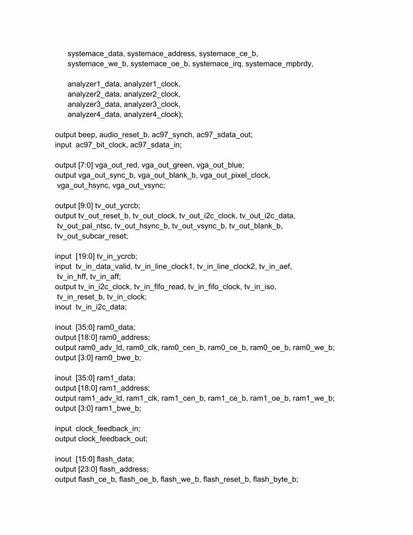
systemace_data, systemace_address, systemace_ce_b, systemace_we_b, systemace_oe_b, systemace_irq, systemace_mpbrdy, analyzer1_data, analyzer1_clock, analyzer2_data, analyzer2_clock, analyzer3_data, analyzer3_clock, analyzer4_data, analyzer4_clock); output beep, audio_reset_b, ac97_synch, ac97_sdata_out; input ac97_bit_clock, ac97_sdata_in; output [7:0] vga_out_red, vga_out_green, vga_out_blue; output vga_out_sync_b, vga_out_blank_b, vga_out_pixel_clock, vga_out_hsync, vga_out_vsync; output [9:0] tv_out_ycrcb; output tv_out_reset_b, tv_out_clock, tv_out_i2c_clock, tv_out_i2c_data, tv_out_pal_ntsc, tv_out_hsync_b, tv_out_vsync_b, tv_out_blank_b, tv_out_subcar_reset; input [19:0] tv_in_ycrcb; input tv_in_data_valid, tv_in_line_clock1, tv_in_line_clock2, tv_in_aef, tv_in_hff, tv_in_aff; output tv_in_i2c_clock, tv_in_fifo_read, tv_in_fifo_clock, tv_in_iso, tv_in_reset_b, tv_in_clock; inout tv_in_i2c_data; inout [35:0] ram0_data; output [18:0] ram0_address; output ram0_adv_ld, ram0_clk, ram0_cen_b, ram0_ce_b, ram0_oe_b, ram0_we_b; output [3:0] ram0_bwe_b; inout [35:0] ram1_data; output [18:0] ram1_address; output ram1_adv_ld, ram1_clk, ram1_cen_b, ram1_ce_b, ram1_oe_b, ram1_we_b; output [3:0] ram1_bwe_b; input clock_feedback_in; output clock_feedback_out; inout [15:0] flash_data; output [23:0] flash_address; output flash_ce_b, flash_oe_b, flash_we_b, flash_reset_b, flash_byte_b;
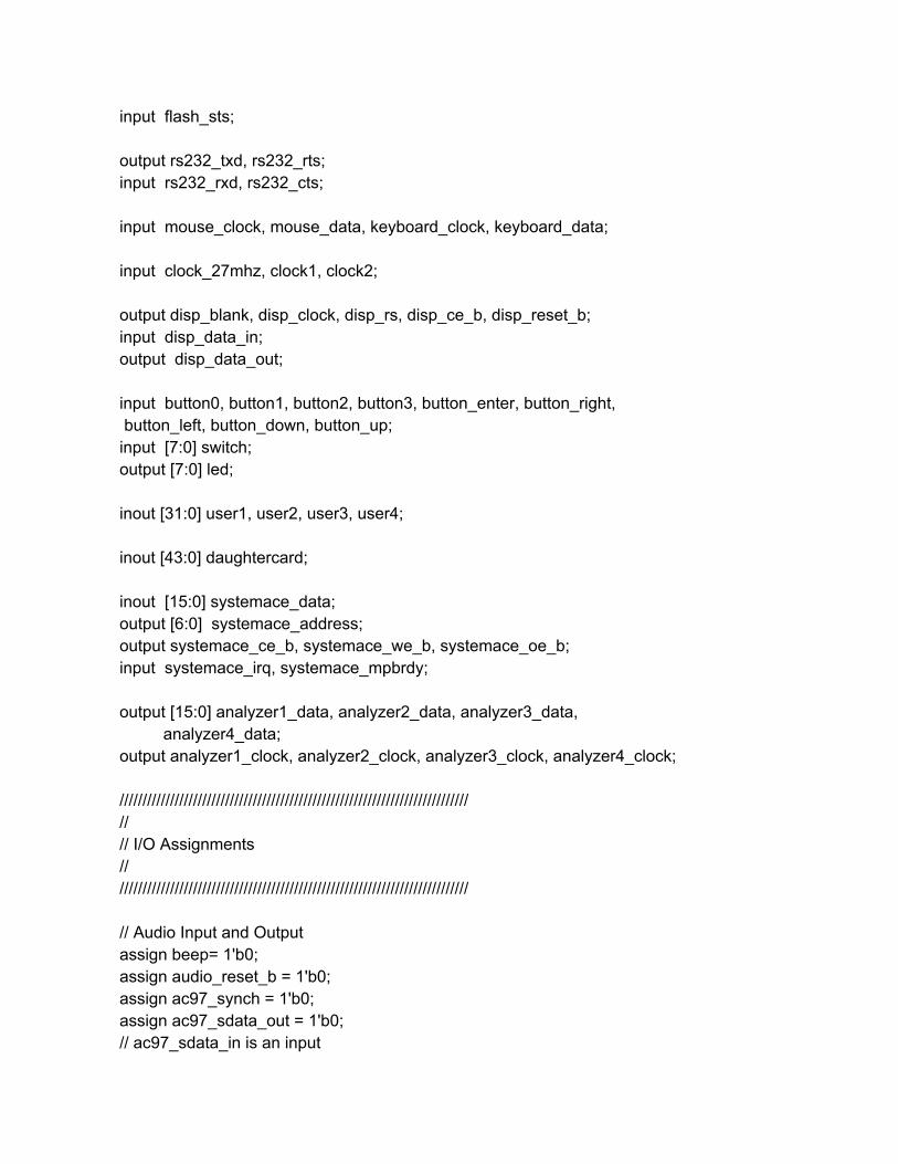
input flash_sts; output rs232_txd, rs232_rts; input rs232_rxd, rs232_cts; input mouse_clock, mouse_data, keyboard_clock, keyboard_data; input clock_27mhz, clock1, clock2; output disp_blank, disp_clock, disp_rs, disp_ce_b, disp_reset_b; input disp_data_in; output disp_data_out; input button0, button1, button2, button3, button_enter, button_right, button_left, button_down, button_up; input [7:0] switch; output [7:0] led; inout [31:0] user1, user2, user3, user4; inout [43:0] daughtercard; inout [15:0] systemace_data; output [6:0] systemace_address; output systemace_ce_b, systemace_we_b, systemace_oe_b; input systemace_irq, systemace_mpbrdy; output [15:0] analyzer1_data, analyzer2_data, analyzer3_data, analyzer4_data; output analyzer1_clock, analyzer2_clock, analyzer3_clock, analyzer4_clock; //////////////////////////////////////////////////////////////////////////// // // I/O Assignments // //////////////////////////////////////////////////////////////////////////// // Audio Input and Output assign beep= 1'b0; assign audio_reset_b = 1'b0; assign ac97_synch = 1'b0; assign ac97_sdata_out = 1'b0; // ac97_sdata_in is an input
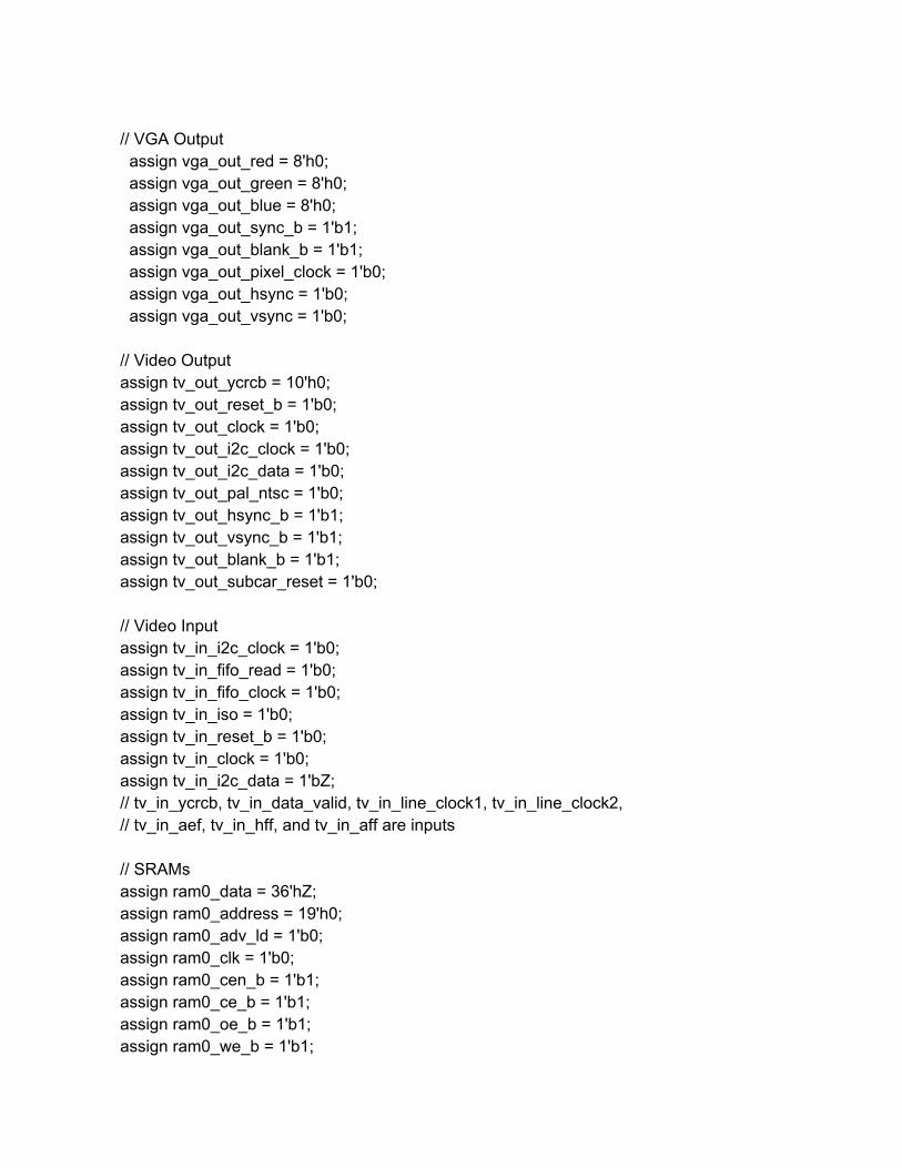
// VGA Output assign vga_out_red = 8'h0; assign vga_out_green = 8'h0; assign vga_out_blue = 8'h0; assign vga_out_sync_b = 1'b1; assign vga_out_blank_b = 1'b1; assign vga_out_pixel_clock = 1'b0; assign vga_out_hsync = 1'b0; assign vga_out_vsync = 1'b0; // Video Output assign tv_out_ycrcb = 10'h0; assign tv_out_reset_b = 1'b0; assign tv_out_clock = 1'b0; assign tv_out_i2c_clock = 1'b0; assign tv_out_i2c_data = 1'b0; assign tv_out_pal_ntsc = 1'b0; assign tv_out_hsync_b = 1'b1; assign tv_out_vsync_b = 1'b1; assign tv_out_blank_b = 1'b1; assign tv_out_subcar_reset = 1'b0; // Video Input assign tv_in_i2c_clock = 1'b0; assign tv_in_fifo_read = 1'b0; assign tv_in_fifo_clock = 1'b0; assign tv_in_iso = 1'b0; assign tv_in_reset_b = 1'b0; assign tv_in_clock = 1'b0; assign tv_in_i2c_data = 1'bZ; // tv_in_ycrcb, tv_in_data_valid, tv_in_line_clock1, tv_in_line_clock2, // tv_in_aef, tv_in_hff, and tv_in_aff are inputs // SRAMs assign ram0_data = 36'hZ; assign ram0_address = 19'h0; assign ram0_adv_ld = 1'b0; assign ram0_clk = 1'b0; assign ram0_cen_b = 1'b1; assign ram0_ce_b = 1'b1; assign ram0_oe_b = 1'b1; assign ram0_we_b = 1'b1;
assign ram0_bwe_b = 4'hF; assign ram1_data = 36'hZ; assign ram1_address = 19'h0; assign ram1_adv_ld = 1'b0; assign ram1_clk = 1'b0; assign ram1_cen_b = 1'b1; assign ram1_ce_b = 1'b1; assign ram1_oe_b = 1'b1; assign ram1_we_b = 1'b1; assign ram1_bwe_b = 4'hF; assign clock_feedback_out = 1'b0; // clock_feedback_in is an input // Flash ROM assign flash_data = 16'hZ; assign flash_address = 24'h0; assign flash_ce_b = 1'b1; assign flash_oe_b = 1'b1; assign flash_we_b = 1'b1; assign flash_reset_b = 1'b0; assign flash_byte_b = 1'b1; // flash_sts is an input // RS232 Interface assign rs232_txd = 1'b1; assign rs232_rts = 1'b1; // rs232_rxd and rs232_cts are inputs // PS/2 Ports // mouse_clock, mouse_data, keyboard_clock, and keyboard_data are inputs // LED Displays // assign disp_blank = 1'b1; // assign disp_clock = 1'b0; // assign disp_rs = 1'b0; // assign disp_ce_b = 1'b1; // assign disp_reset_b = 1'b0; // assign disp_data_out = 1'b0; // disp_data_in is an input // Buttons, Switches, and Individual LEDs //assign led = 8'hFF; // button0, button1, button2, button3, button_enter, button_right,
// button_left, button_down, button_up, and switches are inputs // User I/Os assign user1 = 32'hZ; assign user2 = 32'hZ; assign user3 = 32'hZ; assign user4[31:11] = 0; // Daughtercard Connectors assign daughtercard = 44'hZ; // SystemACE Microprocessor Port assign systemace_data = 16'hZ; assign systemace_address = 7'h0; assign systemace_ce_b = 1'b1; assign systemace_we_b = 1'b1; assign systemace_oe_b = 1'b1; // systemace_irq and systemace_mpbrdy are inputs // Logic Analyzer assign analyzer1_data = 16'h0; assign analyzer1_clock = 1'b1; assign analyzer2_data = 16'h0; assign analyzer2_clock = 1'b1; assign analyzer3_data = 16'h0; assign analyzer3_clock = 1'b1; assign analyzer4_data = 16'h0; assign analyzer4_clock = 1'b1;
//////////////////////////////////////////////////////////////////////////// // // Reset Generation // // A shift register primitive is used to generate an activehigh reset // signal that remains high for 16 clock cycles after configuration finishes // and the FPGA's internal clocks begin toggling. // //////////////////////////////////////////////////////////////////////////// wire reset; SRL16 reset_sr(.D(1'b0), .CLK(clock_27mhz), .Q(reset),
.A0(1'b1), .A1(1'b1), .A2(1'b1), .A3(1'b1)); defparam reset_sr.INIT = 16'hFFFF;
wire [7:0] hover, roll, pitch; wire on; wire [3:0] btc_state; wire [3:0] debug;
wire [15:0] left_x,left_y,left_z; wire [15:0] right_x,right_y,right_z; wire data_ready;
wire [15:0] x1,y1,z1,x2,y2,z2; wire newout;
wire initialize_debug;
assign led = 6'b111111,!initialize_debug, !on;
display_16hex hex(.reset(reset), .clock_27mhz(clock_27mhz), .data(48'd0, roll, hover),
.disp_blank(disp_blank), .disp_clock(disp_clock), .disp_rs(disp_rs), .disp_ce_b(disp_ce_b),
.disp_reset_b(disp_reset_b), .disp_data_out(disp_data_out)); //////////////////////////////////////////////////////////////////////////// // // Gestures > hover, pitch and roll // ////////////////////////////////////////////////////////////////////////////
Bytes_to_Coords btc( .clock(clock_27mhz), .reset(reset),.rxf(user4[9]),.rd(user4[8]), .data(user4[7:0]),.ready(data_ready), .x1(x1),.y1(y1),.z1(z1), .x2(x2),.y2(y2),.z2(z2), .newout(newout),.state(btc_state),.debug(debug));
setHandLocations set_hands(
.x1(x1),.y1(y1),.z1(z1), .x2(x2),.y2(y2),.z2(z2), .left_x(left_x),.left_y(left_y),.left_z(left_z), .right_x(right_x),.right_y(right_y),.right_z(right_z) );

gest_rec gr( .clock(clock_27mhz), .left_x(left_x),.left_y(left_y),.left_z(left_z), .right_x(right_x),.right_y(right_y),.right_z(right_z), .reset(!button_down), .hover(hover),.roll(roll),.pitch(pitch), .on(on));
assign user4[10] = on; //////////////////////////////////////////////////////////////////////////// // // Initialize Controller // ////////////////////////////////////////////////////////////////////////////
wire [7:0] initial_signal; Initialize_Remote ir(.clock(clock_27mhz),
.on_state(on),
.initial_signal(initial_signal),
.debug(initialize_debug)); //////////////////////////////////////////////////////////////////////////// // // Write to DAC // //////////////////////////////////////////////////////////////////////////// wire write_signal; wire [7:0] gest_out; wire [1:0] gest_select; assign user3[10] = write_signal; assign user3[7:0] = gest_out; assign user3[9:8] = gest_select;
write_to_DAC wtc(.clock(clock_27mhz), .hover(switch[7:0]|hover[7:0]|initial_signal), .pitch(pitch), .roll(roll), .write_signal(write_signal), .gest_select(gest_select), .gest_out(gest_out));
//////////////////////////////////////////////////////////////////////////// // // Final Project // //////////////////////////////////////////////////////////////////////////// // use FPGA's digital clock manager to produce a // 65MHz clock (actually 64.8MHz) wire clock_65mhz_unbuf,clock_65mhz; DCM vclk1(.CLKIN(clock_27mhz),.CLKFX(clock_65mhz_unbuf)); // synthesis attribute CLKFX_DIVIDE of vclk1 is 10 // synthesis attribute CLKFX_MULTIPLY of vclk1 is 24 // synthesis attribute CLK_FEEDBACK of vclk1 is NONE // synthesis attribute CLKIN_PERIOD of vclk1 is 37 BUFG vclk2(.O(clock_65mhz),.I(clock_65mhz_unbuf)); // generate basic XVGA video signals wire [10:0] hcount; wire [9:0] vcount; wire hsync,vsync,blank; xvga xvga1(.vclock(clock_65mhz),
.hcount(hcount),
.vcount(vcount), .hsync(hsync),
.vsync(vsync),
.blank(blank)); // feed XVGA signals to user's pong game wire [23:0] pixel; wire phsync,pvsync,pblank;
assign reset = 0; hand_locations_display pg(.vclock(clock_65mhz),
.hcount(hcount),
.vcount(vcount), .hsync(hsync),
.vsync(vsync),
.blank(blank),
.phsync(phsync),
.pvsync(pvsync),
.pblank(pblank),
.pixel(pixel),
.on(on),
.x1(left_x), .y1(left_y), .z1(left_z), .x2(right_x), .y2(right_y), .z2(right_z)); reg [23:0] rgb; reg b,hs,vs; always @(posedge clock_65mhz) begin
hs <= phsync; vs <= pvsync; b <= pblank; rgb <= pixel;
end // VGA Output. In order to meet the setup and hold times of the // AD7125, we send it ~clock_65mhz. assign vga_out_red = rgb[23:16]; assign vga_out_green = rgb[15:8]; assign vga_out_blue = rgb[7:0]; assign vga_out_sync_b = 1'b1; // not used assign vga_out_blank_b = ~b; assign vga_out_pixel_clock = ~clock_65mhz; assign vga_out_hsync = hs; assign vga_out_vsync = vs; endmodule ///////////////////////////////////////////////////////// // // // // // // // ////////////////////ASCII_to_Num.v////////////////////////
module ASCII_to_Num( input clock, input reset, input [7:0] ascii, output [7:0] num,
output [1:0] coords_state ); parameter NUM = 2'b11; //when char contains a num parameter START = 2'b01; //when start sending new coors parameter END = 2'b10; //when end sending set of coords parameter NULL = 2'b00; assign num = (ascii < 8'd58 && ascii > 8'd47)? ascii8'd48:0; assign coords_state = (ascii == 8'd83)? START:
(ascii == 8'd69)?END: (ascii < 8'd58 && ascii > 8'd47)?NUM:NULL;
endmodule ///////////////////////////////////////////////////////// // // // // // // // // ////////////////////blob.v//////////////////////// ///////////////(taken from course website)//////// module blob #(parameter WIDTH = 64, // default width: 64 pixels HEIGHT = 64) // default color: white (input [10:0] x,hcount, input [9:0] y,vcount,
input [23:0] color, output reg [23:0] pixel); always @ * begin if ((hcount >= x && hcount < (x+WIDTH)) &&
(vcount >= y && vcount < (y+HEIGHT))) pixel = color;
else pixel = 0;
end endmodule ///////////////////////////////////////////////////////// // // // // // // // // ////////////////////Bytes_to_Coords.v//////////////////////// //takes 8 bit data from USB input module and converts to the hand coordinates module Bytes_to_Coords( input clock, input reset,
input rxf, input [7:0] data,
output rd, output reg ready,
output reg [15:0] x1, output reg [15:0] y1, output reg [15:0] z1, output reg [15:0] x2, output reg [15:0] y2, output reg [15:0] z2,
output newout, output reg [3:0] state, output [3:0] debug
); //state parameter for coords state parameter NUM = 2'b11; //when char contains a num parameter COORDS_START = 2'b01; //when start sending new coords parameter NULL = 2'b00; wire [7:0] current_num; wire [1:0] coords_state; //states for reading states parameter IDLE = 4'd0; parameter START = 4'd14;
parameter X1_MSB = 4'd2; parameter X1_LSB = 4'd3; parameter Y1_MSB = 4'd4; parameter Y1_LSB = 4'd5; parameter Z1_MSB = 4'd6; parameter Z1_LSB = 4'd7; parameter X2_MSB = 4'd8; parameter X2_LSB = 4'd9; parameter Y2_MSB = 4'd10; parameter Y2_LSB = 4'd11; parameter Z2_MSB = 4'd12; parameter Z2_LSB = 4'd13; parameter DONE = 4'd1; reg hold = 0; wire [7:0] data_byte; reg done_writing = 0; reg reset_usb; ASCII_to_Num atn(.clock(clock),
.reset(reset), .ascii(data_byte), .num(current_num), .coords_state(coords_state));
usb_input usb_i(.clk(clock),
.reset(reset_usb),
.data(data), //incoming data from usb .rd(rd),
.rxf(rxf), .out(data_byte), //output data not always valid .newout(newout), //signals out is valid .hold(hold), .state(debug));
reg flag = 0; always @(posedge clock) begin
if (!flag) begin state <= IDLE; flag = !flag;
end else begin
case (state) START: begin
if (newout) begin state <= X1_MSB; hold <= 1; end
end X1_MSB: begin
if (!done_writing) begin x1[15:8] <= data_byte; //current_num; done_writing <= 1; hold <= 0; end else if (newout) begin
done_writing <= 0; state <= X1_LSB; hold <= 1;
end end X1_LSB: begin
if (!done_writing) begin x1[7:0] <= data_byte; //current_num; done_writing <= 1; hold <= 0;
end else if (newout) begin done_writing <= 0; state <= Y1_MSB; hold <= 1;
end end Y1_MSB: begin
if (!done_writing) begin y1[15:8] <= data_byte; //current_num; done_writing <= 1; hold <= 0;
end else if (newout) begin done_writing <= 0; state <= Y1_LSB; hold <= 1;
end
end Y1_LSB: begin
if (!done_writing) begin done_writing <= 1; y1[7:0] <= data_byte; //current_num; hold <= 0;
end else if (newout) begin done_writing <= 0; state <= Z1_MSB; hold <= 1;
end end Z1_MSB: begin
if (!done_writing) begin done_writing <= 1; z1[15:8] <= data_byte; //current_num; hold <= 0;
end else if (newout) begin state <= Z1_LSB; done_writing <= 0; hold <= 1;
end end Z1_LSB: begin
if (!done_writing) begin done_writing <= 1; z1[7:0] <= data_byte; //current_num; hold <= 0;
end else if (newout) begin state <= X2_MSB; done_writing <= 0; hold <= 1;
end end X2_MSB: begin
if (!done_writing) begin done_writing <= 1; x2[15:8] <= data_byte; //current_num; hold <= 0;
end else if (newout) begin state <= X2_LSB; done_writing <= 0; hold <= 1;
end end X2_LSB: begin
if (!done_writing) begin done_writing <= 1; x2[7:0] <= data_byte; //current_num; hold <= 0;
end else if (newout) begin state <= Y2_MSB; done_writing <= 0; hold <= 1;
end end Y2_MSB: begin
if (!done_writing) begin done_writing <= 1; y2[15:8] <= data_byte; //current_num; hold <= 0;
end else if (newout) begin state <= Y2_LSB; done_writing <= 0; hold <= 1;
end end Y2_LSB: begin
if (!done_writing) begin done_writing <= 1; y2[7:0] <= data_byte; //current_num; hold <= 0;
end else if (newout) begin state <= Z2_MSB; done_writing <= 0; hold <= 1;
end end Z2_MSB:
begin if (!done_writing) begin
done_writing <= 1; z2[15:8] <= data_byte; //current_num; hold <= 0;
end else if (newout) begin state <= Z2_LSB; done_writing <= 0; hold <= 1;
end end Z2_LSB: begin
z2[7:0] <= data_byte; //current_num; state <= DONE; ready <= 1;
end DONE: begin
state <= IDLE; ready <= 0; hold <= 0;
end default: begin
if (newout && coords_state == COORDS_START) state <=
START; end
endcase end
end endmodule ///////////////////////////////////////////////////////// // // // // // // //
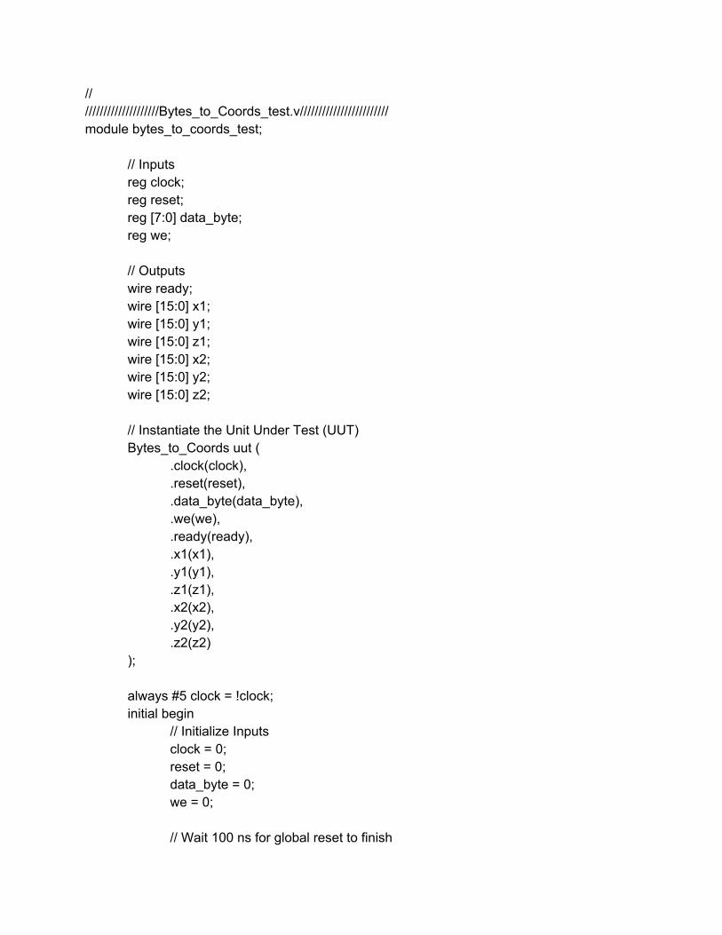
// ////////////////////Bytes_to_Coords_test.v//////////////////////// module bytes_to_coords_test;
// Inputs reg clock; reg reset; reg [7:0] data_byte; reg we;
// Outputs wire ready; wire [15:0] x1; wire [15:0] y1; wire [15:0] z1; wire [15:0] x2; wire [15:0] y2; wire [15:0] z2;
// Instantiate the Unit Under Test (UUT) Bytes_to_Coords uut (
.clock(clock),
.reset(reset),
.data_byte(data_byte),
.we(we),
.ready(ready),
.x1(x1),
.y1(y1),
.z1(z1),
.x2(x2),
.y2(y2),
.z2(z2) );
always #5 clock = !clock; initial begin
// Initialize Inputs clock = 0; reset = 0; data_byte = 0; we = 0;
// Wait 100 ns for global reset to finish
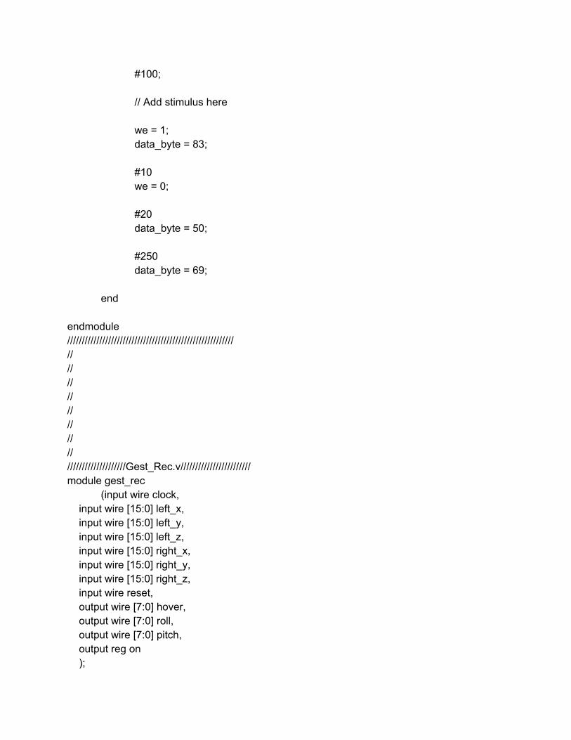
#100;
// Add stimulus here
we = 1; data_byte = 83;
#10 we = 0;
#20 data_byte = 50;
#250 data_byte = 69;
end
endmodule ///////////////////////////////////////////////////////// // // // // // // // // ////////////////////Gest_Rec.v//////////////////////// module gest_rec
(input wire clock, input wire [15:0] left_x, input wire [15:0] left_y, input wire [15:0] left_z, input wire [15:0] right_x, input wire [15:0] right_y, input wire [15:0] right_z, input wire reset, output wire [7:0] hover, output wire [7:0] roll, output wire [7:0] pitch, output reg on );
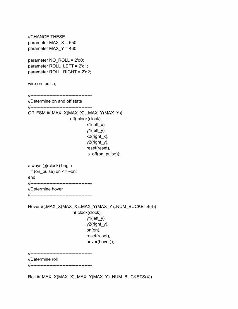
//CHANGE THESE parameter MAX_X = 650; parameter MAX_Y = 460; parameter NO_ROLL = 2'd0; parameter ROLL_LEFT = 2'd1; parameter ROLL_RIGHT = 2'd2; wire on_pulse; // //Determine on and off state // Off_FSM #(.MAX_X(MAX_X), .MAX_Y(MAX_Y))
off(.clock(clock), .x1(left_x), .y1(left_y), .x2(right_x), .y2(right_y), .reset(reset), .is_off(on_pulse));
always @(clock) begin if (on_pulse) on <= ~on; end // //Determine hover // Hover #(.MAX_X(MAX_X),.MAX_Y(MAX_Y),.NUM_BUCKETS(4))
h(.clock(clock), .y1(left_y), .y2(right_y), .on(on), .reset(reset), .hover(hover));
// //Determine roll // Roll #(.MAX_X(MAX_X),.MAX_Y(MAX_Y),.NUM_BUCKETS(4))
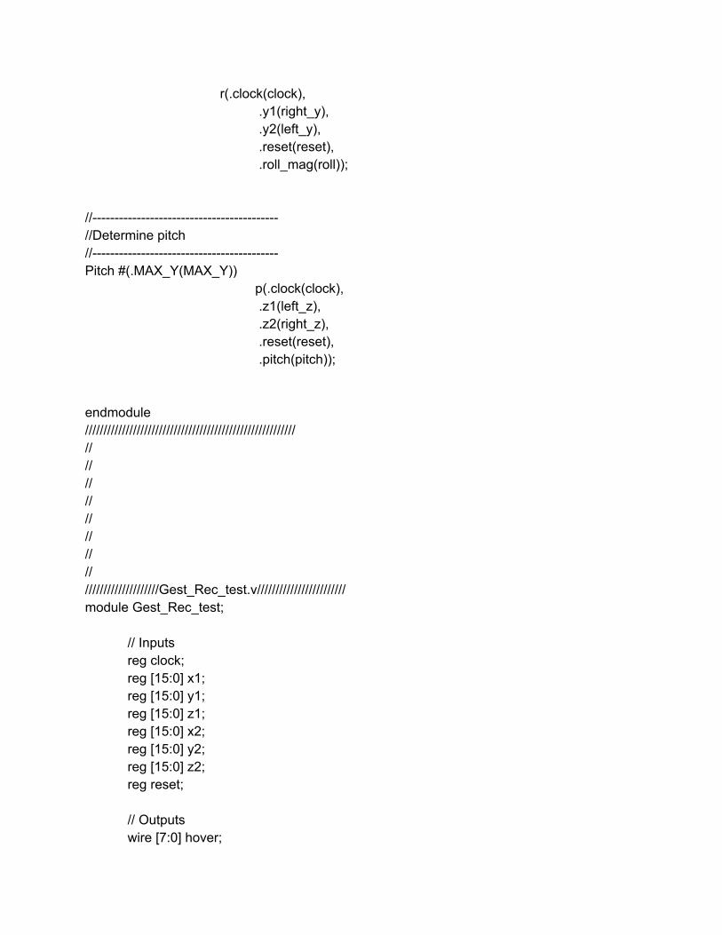
r(.clock(clock), .y1(right_y), .y2(left_y), .reset(reset), .roll_mag(roll));
// //Determine pitch // Pitch #(.MAX_Y(MAX_Y))
p(.clock(clock), .z1(left_z),
.z2(right_z), .reset(reset), .pitch(pitch));
endmodule ///////////////////////////////////////////////////////// // // // // // // // // ////////////////////Gest_Rec_test.v//////////////////////// module Gest_Rec_test;
// Inputs reg clock; reg [15:0] x1; reg [15:0] y1; reg [15:0] z1; reg [15:0] x2; reg [15:0] y2; reg [15:0] z2; reg reset;
// Outputs wire [7:0] hover;
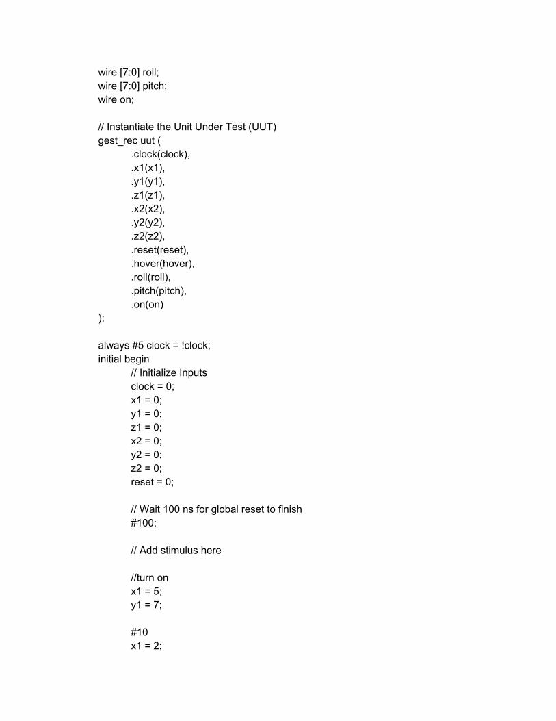
wire [7:0] roll; wire [7:0] pitch; wire on;
// Instantiate the Unit Under Test (UUT) gest_rec uut (
.clock(clock),
.x1(x1),
.y1(y1),
.z1(z1),
.x2(x2),
.y2(y2),
.z2(z2),
.reset(reset),
.hover(hover),
.roll(roll),
.pitch(pitch),
.on(on) );
always #5 clock = !clock; initial begin
// Initialize Inputs clock = 0; x1 = 0; y1 = 0; z1 = 0; x2 = 0; y2 = 0; z2 = 0; reset = 0;
// Wait 100 ns for global reset to finish #100;
// Add stimulus here
//turn on x1 = 5; y1 = 7;
#10 x1 = 2;
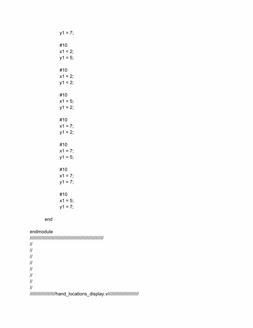
y1 = 7;
#10 x1 = 2; y1 = 5;
#10 x1 = 2; y1 = 2;
#10 x1 = 5; y1 = 2;
#10 x1 = 7; y1 = 2;
#10 x1 = 7; y1 = 5;
#10 x1 = 7; y1 = 7;
#10 x1 = 5; y1 = 7;
end
endmodule ///////////////////////////////////////////////////////// // // // // // // // // ////////////////////hand_locations_display.v////////////////////////
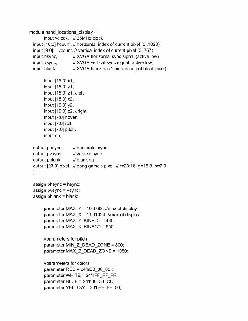
module hand_locations_display ( input vclock, // 65MHz clock
input [10:0] hcount, // horizontal index of current pixel (0..1023) input [9:0] vcount, // vertical index of current pixel (0..767) input hsync, // XVGA horizontal sync signal (active low) input vsync, // XVGA vertical sync signal (active low) input blank, // XVGA blanking (1 means output black pixel)
input [15:0] x1, input [15:0] y1, input [15:0] z1, //left input [15:0] x2, input [15:0] y2, input [15:0] z2, //right input [7:0] hover, input [7:0] roll, input [7:0] pitch, input on,
output phsync, // horizontal sync output pvsync, // vertical sync output pblank, // blanking output [23:0] pixel // pong game's pixel // r=23:16, g=15:8, b=7:0 ); assign phsync = hsync; assign pvsync = vsync; assign pblank = blank;
parameter MAX_Y = 10'd768; //max of display parameter MAX_X = 11'd1024; //max of display parameter MAX_Y_KINECT = 460; parameter MAX_X_KINECT = 650;
//parameters for pitch parameter MIN_Z_DEAD_ZONE = 800; parameter MAX_Z_DEAD_ZONE = 1050;
//parameters for colors parameter RED = 24'hD0_00_00 ; parameter WHITE = 24'hFF_FF_FF; parameter BLUE = 24'h00_33_CC; parameter YELLOW = 24'hFF_FF_00;

parameter DEAD_ZONE_COLOR = 24'h30_30_30; parameter BLACK = 24'h00_00_00; parameter gesture_lines_color = 24'h50_50_50 ;
reg [15:0] x1_disp; reg [15:0] y1_disp; reg [15:0] x2_disp; reg [15:0] y2_disp;
reg [23:0] left_hand_color; reg [23:0] right_hand_color; wire [23:0] divider_color = WHITE ;
wire [23:0] left_hand_pixel; wire [23:0] right_hand_pixel; wire [23:0] dead_zone_pixel; wire [23:0] divider_pixel; wire [23:0] dead_zone_line_pixel; wire [23:0] on_pixel;
always @(negedge vsync) begin
x1_disp <= (x1/2)*3; y1_disp <= (y1/2)*3; x2_disp <= (x2/2)*3; y2_disp <= (y2/2)*3;
if (z1 < MIN_Z_DEAD_ZONE) left_hand_color <= BLUE;// else if (z1 < MAX_Z_DEAD_ZONE) left_hand_color <= WHITE;// else left_hand_color <= RED;
if (z2 < MIN_Z_DEAD_ZONE) right_hand_color <= BLUE;// else if (z2 < MAX_Z_DEAD_ZONE) right_hand_color <= WHITE;// else right_hand_color <= RED;
end
//////////////////////////////////////////////////////////////////////////// // // Hands // ////////////////////////////////////////////////////////////////////////////
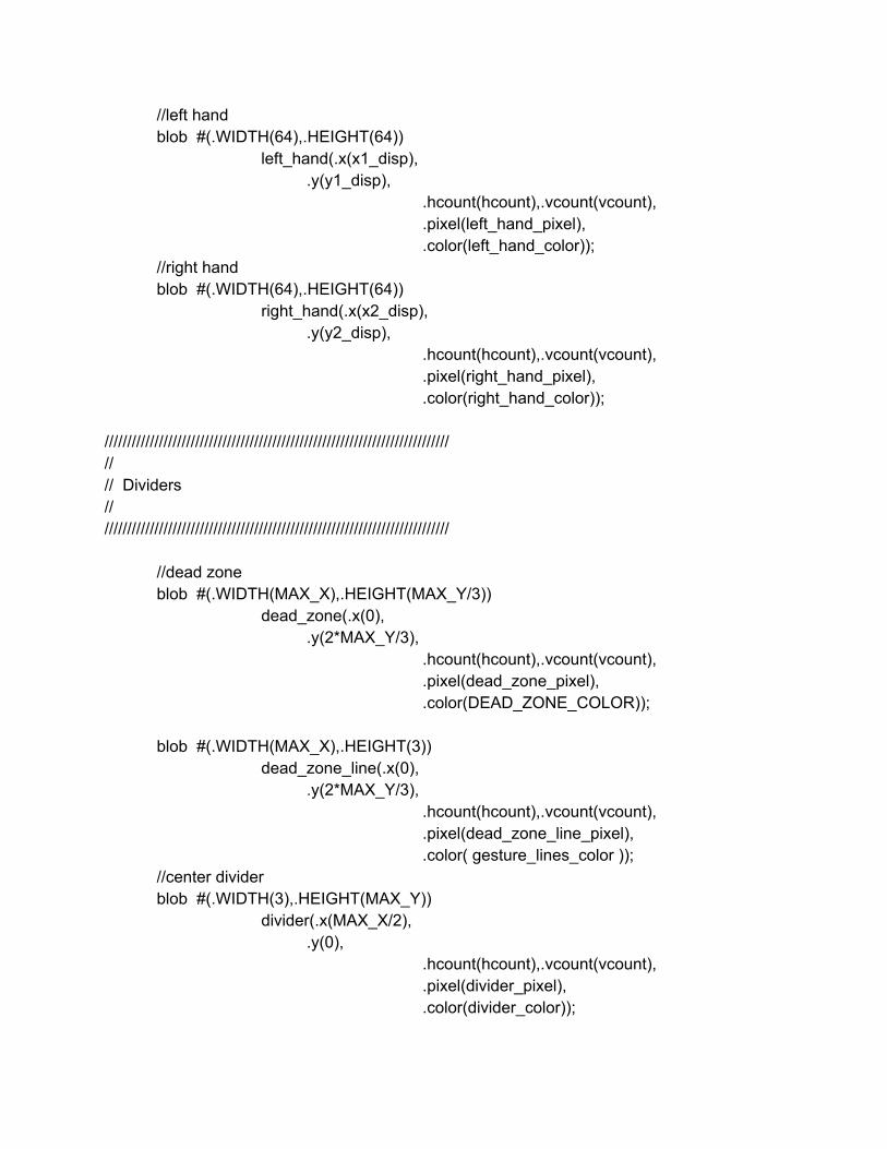
//left hand blob #(.WIDTH(64),.HEIGHT(64))
left_hand(.x(x1_disp), .y(y1_disp),
.hcount(hcount),.vcount(vcount), .pixel(left_hand_pixel), .color(left_hand_color));
//right hand blob #(.WIDTH(64),.HEIGHT(64))
right_hand(.x(x2_disp), .y(y2_disp),
.hcount(hcount),.vcount(vcount), .pixel(right_hand_pixel), .color(right_hand_color));
//////////////////////////////////////////////////////////////////////////// // // Dividers // ////////////////////////////////////////////////////////////////////////////
//dead zone blob #(.WIDTH(MAX_X),.HEIGHT(MAX_Y/3))
dead_zone(.x(0), .y(2*MAX_Y/3),
.hcount(hcount),.vcount(vcount), .pixel(dead_zone_pixel), .color(DEAD_ZONE_COLOR));
blob #(.WIDTH(MAX_X),.HEIGHT(3))
dead_zone_line(.x(0), .y(2*MAX_Y/3),
.hcount(hcount),.vcount(vcount), .pixel(dead_zone_line_pixel), .color( gesture_lines_color ));
//center divider blob #(.WIDTH(3),.HEIGHT(MAX_Y))
divider(.x(MAX_X/2), .y(0),
.hcount(hcount),.vcount(vcount), .pixel(divider_pixel), .color(divider_color));
//////////////////////////////////////////////////////////////////////////// // // Dividing lines for off gesture // ////////////////////////////////////////////////////////////////////////////
parameter line1 = MAX_X/5; parameter line2 = 2*MAX_X/5; parameter line3 = 3*MAX_X/5; parameter line4 = 4*MAX_X/5; wire [23:0] line1_pixel,line2_pixel,line3_pixel,line4_pixel;
blob #(.WIDTH(3),.HEIGHT(2*MAX_Y/3))
l1(.x(line1), .y(2*MAX_Y/3),
.hcount(hcount),.vcount(vcount), .pixel(line1_pixel), .color( gesture_lines_color ));
blob #(.WIDTH(3),.HEIGHT(2*MAX_Y/3))
l2(.x(line2),.y(2*MAX_Y/3),.hcount(hcount),.vcount(vcount), .pixel(line2_pixel), .color( gesture_lines_color ));
blob #(.WIDTH(3),.HEIGHT(2*MAX_Y/3))
l3(.x(line3),.y(2*MAX_Y/3),.hcount(hcount),.vcount(vcount), .pixel(line3_pixel),.color( gesture_lines_color ));
blob #(.WIDTH(3),.HEIGHT(2*MAX_Y/3))
l4(.x(line4),.y(2*MAX_Y/3),.hcount(hcount),.vcount(vcount), .pixel(line4_pixel),.color( gesture_lines_color ));
//////////////////////////////////////////////////////////////////////////// // // ON // ////////////////////////////////////////////////////////////////////////////
wire [23:0] on_blob_color; assign on_blob_color = on? YELLOW:BLACK; blob #(.WIDTH(64 ),.HEIGHT(64))
on1(.x(MAX_X64),.y(0),.hcount(hcount),.vcount(vcount),
.pixel(on_pixel),.color( on_blob_color ));
//draw mags for hover, pitch and roll
wire [23:0] h_rec_pixel,h_mag_pixel; parameter GRAY = 24'h98_98_98; parameter GREEN = 24'h00_66_33; wire [23:0] h_mag_val1; wire [23:0] h_mag_val; parameter b_t = 2*MAX_Y/3; assign h_mag_val1 = hover[7:0]*b_t; assign h_mag_val[23:0] = 8'b0, h_mag_val1[23:16];
// //bounding rectangle for hover
// blob #(.WIDTH(100),.HEIGHT(2*MAX_Y/3)) // hover_rec(.x(0), // .y(2*MAX_Y/3), // .hcount(hcount),.vcount(vcount), // .pixel(h_rec_pixel), // .color( GRAY )); // //hover mag // blob #(.WIDTH(100),.HEIGHT(2*MAX_Y/3)) // hover_mag(.x(0), // .y(2*MAX_Y/3), // .hcount(hcount),.vcount(vcount), // .pixel(h_mag_pixel), // .color( GREEN )); //
assign pixel = left_hand_pixel | right_hand_pixel | dead_zone_pixel | divider_pixel
|line1_pixel|line2_pixel|line3_pixel|line4_pixel|
dead_zone_line_pixel|on_pixel|h_mag_pixel|h_rec_pixel; endmodule ///////////////////////////////////////////////////////// // // // // // //
// // ////////////////////Hover.v//////////////////////// module Hover
#(parameter MAX_X = 650, //1024 MAX_Y = 460, //767
NUM_BUCKETS = 4) (input clock,
input [15:0] y1, input [15:0] y2, input reset,
input on, output reg [7:0] hover ); reg [16:0] y_sum; reg [15:0] y; //average y's parameter b_t = 2*MAX_Y/3; //if either hand in dead zone, hover = 0 //if one hand is not sent, then only consider the hand that is sending //else average the hands always @(*) begin
if (y1 > b_t || y2 > b_t|| (y1==0 && y2==0)) y <= 9'd320; //turn off else if (y1 == 0) y <= y2; else if (y2 == 0) y <= y1; else begin
y_sum <= y1+y2; y <= y_sum[16:1];
end end //convert height to hover signal //max hover is 50% > 128 bits always @(*) begin
if (y <50) hover <= 8'd128; else if (y > 0 && y < b_t && on) hover <= 8'd160 y[8:1]; else hover <= 0;
end endmodule /////////////////////////////////////////////////////////
// // // // // // // // ////////////////////Hover_test.v//////////////////////// module Hover_test;
// Inputs reg clock; reg [15:0] y1; reg [15:0] y2; reg reset; reg on;
// Outputs wire [7:0] hover;
// Instantiate the Unit Under Test (UUT) Hover uut (
.clock(clock),
.y1(y1),
.y2(y2),
.reset(reset),
.on(on),
.hover(hover) );
always #5 clock = !clock; initial begin
// Initialize Inputs clock = 0; y1 = 0; y2 = 0; reset = 0; on = 0;
// Wait 100 ns for global reset to finish #100;
// Add stimulus here y1 = 20; y2 = 20;
#20 y1 = 12; y2 = 12;
#20 on = 1;
#20 y1 = 8; y2 = 8;
#20 on = 0;
#20 y1 = 4; y2 = 4;
#20 y1 = 16; y2 = 16;
end endmodule ///////////////////////////////////////////////////////// // // // // // // // // ////////////////////Initialize_Remote.v//////////////////////// module Initialize_Remote(
input clock, input on_state, output reg [7:0] initial_signal, output reg debug
); parameter TURN_ON = 1; parameter IDLE = 0; reg state; reg [25:0] counter; reg first_time; initial counter = 0; initial first_time = 0; //when you get an on pulse, //send out 0 for 16 cycles, //then 255 for 16 cycles, then //0 always @(clock) begin
case (state) TURN_ON: begin
first_time <= 1; //if (counter > 26'd280 && counter < 26'd540) begin if (counter > 26'd28000000 && counter < 26'd54000000) begin
initial_signal <= 8'b1111_1111; end else if (counter > 26'd54000000) begin //end else if (counter > 26'd540) begin initial_signal <= 0;
state <= IDLE; end else initial_signal <= 0;
counter <= counter +1; debug <= state;
end default: begin
initial_signal <= 0; if (!first_time) state <= TURN_ON; else state <= IDLE;
end endcase
end
endmodule ///////////////////////////////////////////////////////// // // // // // // // // ////////////////////initialize_test.v//////////////////////// module initialize_test;
// Inputs reg clock; reg on_state;
// Outputs wire [7:0] initial_signal;
// Instantiate the Unit Under Test (UUT) Initialize_Remote uut (
.clock(clock),
.on_state(on_state),
.initial_signal(initial_signal) );
always #5 clock = !clock; initial begin
// Initialize Inputs clock = 0; on_state = 0;
// Wait 100 ns for global reset to finish #100;
// Add stimulus here #15 on_state = 1;
#4000 on_state = 0;
#500 on_state = 1;
end
endmodule ///////////////////////////////////////////////////////// // // // // // // // // ////////////////////OFF_FSM.v//////////////////////// module Off_FSM
#(parameter MAX_X = 15, //1024 MAX_Y = 15) //767
( input clock, input [15:0] x1,//left hand input [15:0] y1, input [15:0] x2, //right hand input [15:0] y2, input reset, output reg is_off,
output reg [4:0] state_right ); //states parameter IDLE = 4'd5; parameter STEP0 = 4'd0; //when hands are at center parameter STEP1 = 4'd1; //first step to left or right parameter STEP2 = 4'd2; //second step to left or right parameter STEP3 = 4'd3; //third step back towards center parameter STEP4 = 4'd4; //fourth step hand returns to center reg [4:0] state_left = IDLE; //reg [4:0] state_right = IDLE; //dividing lines
parameter line0 = 0; parameter line1 = MAX_X/5; parameter line2 = 2*MAX_X/5; parameter line3 = 3*MAX_X/5; parameter line4 = 4*MAX_X/5; parameter line5 = MAX_X; parameter boundary = 2*MAX_Y/3; //bottom third of the screen reg [5:0] buffer; parameter CUTOFF = 30; always @(posedge clock) begin
if (reset) begin state_left <= IDLE; state_right <= IDLE;
end //if both hands have gone to the sides and back then set a pulse to indicate turning off else if (state_left == STEP4 || state_right == STEP4) begin
is_off <=1; state_left <=IDLE; state_right <=IDLE;
end else if (y1 > boundary || y2 > boundary) begin
if (y1 > boundary) begin case (state_left)
STEP0: //stay in Step0, go to Step1 or IDLE begin
if (x1 > line2 && x1 <line3) begin state_left <= STEP0; buffer <= 0;
end else if (x1>line1 && x1<line2) state_left <=STEP1; else begin
if (buffer < CUTOFF) begin buffer <= buffer +1;
end else state_right <= IDLE;
end end STEP1: //stay in Step1, go to Step2 or IDLE begin
if (x1>line1 && x1<line2) begin
state_left <=STEP1; buffer <= 0;
end else if (x1>line0 && x1<line1) state_left <=STEP2; else begin
if (buffer < CUTOFF) begin buffer <= buffer +1;
end else state_right <= IDLE;
end end STEP2: //stay in Step2, go to Step3 or IDLE begin
if (x1>=line0 && x1<=line1) begin state_left <=STEP2; buffer <= 0;
end else if (x1>=line1 && x1<=line2) state_left <=STEP3; else begin
if (buffer < CUTOFF) begin buffer <= buffer +1;
end else state_right <= IDLE;
end end STEP3: //stay in Step3, go to Step4 or IDLE begin
if (x1>=line1 && x1<=line2) begin state_left <=STEP3; buffer <= 0;
end else if (x1>=line2 && x1<=line3) state_left <=STEP4; else begin
if (buffer < CUTOFF) begin buffer <= buffer +1;
end else state_right <= IDLE;
end end STEP4: state_right <= STEP4; default: begin
if (x1 >= line2 && x1 <=line3) state_left <= STEP0;
is_off <=0; buffer <= 0;
end endcase
end if (y2 > boundary) begin
case (state_right) STEP0: //stay in Step0, go to Step1 or IDLE begin
if (x2 > line2 && x2 <line3) begin state_right <= STEP0; buffer <= 0;
end else if (x2>line3 && x2<line4) state_right <=STEP1; else begin
if (buffer < CUTOFF) begin buffer <= buffer +1;
end else state_right <= IDLE;
end end STEP1: //stay in Step1, go to Step2 or IDLE begin
if (x2>line3 && x2<line4) begin state_right <=STEP1; buffer <= 0;
end else if (x2>line4 && x2<line5) state_right <=STEP2; else begin
if (buffer < CUTOFF) begin buffer <= buffer +1;
end else state_right <= IDLE;
end end STEP2: //stay in Step2, go to Step3 or IDLE begin
if (x2>=line4) begin state_right <=STEP2; buffer <= 0;
end else if (x2>=line3 && x2<=line4) state_right <=STEP3; else begin
if (buffer < CUTOFF) begin buffer <= buffer +1;
end else state_right <= IDLE;
end end STEP3: //stay in Step3, go to Step4 or IDLE begin
if (x2>=line3 && x2<=line4) begin state_right <=STEP3; buffer <= 0;
end else if (x2>=line2 && x2<=line3) state_right <=STEP4; else begin
if (buffer < CUTOFF) begin buffer <= buffer +1;
end else state_right <= IDLE;
end end STEP4: state_right <= STEP4; default: begin
if (x2 > line2 && x2 <line3) state_right <= STEP0; is_off <=0; buffer <=0;
end endcase
end
end else begin
is_off <= 0; end
end ///////////////////////////////////////////////////////// // // // // // //

// // ////////////////////OFF_FSM_test.v//////////////////////// module Off_FSM_test;
// Inputs reg clock; reg [10:0] x1; reg [10:0] y1; reg [10:0] x2; reg [10:0] y2; reg reset;
// Outputs wire is_off;
// Instantiate the Unit Under Test (UUT) Off_FSM uut (
.clock(clock),
.x1(x1),
.y1(y1),
.x2(x2),
.y2(y2),
.reset(reset),
.is_off(is_off) );
always #5 clock = !clock; initial begin
// Initialize Inputs clock = 0; x1 = 0; y1 = 0; x2 = 0; y2 = 0; reset = 0;
// Wait 100 ns for global reset to finish #100;
// Add stimulus here y1 = 12; y2 = 12;
x1 = 7;
#10 x1 = 4;
#10 x1 = 1;
#10 x1 = 4;
#10 x1 = 7;
#10 x2 = 7;
#10 x2 = 10;
#10 x2 = 13;
#10 x2 = 10;
#10 x2 = 7;
end
endmodule ///////////////////////////////////////////////////////// // // // // // // // // ////////////////////Pitch.v//////////////////////// module Pitch
#(parameter MAX_Y = 650) (input clock,
input [15:0] z1, input [15:0] z2, input reset, output reg [7:0] pitch );
//parameters for pitch parameter MIN_Z_DEAD_ZONE = 800; parameter MAX_Z_DEAD_ZONE = 1050;
parameter MOVE_BACK = 8'd58; parameter MOVE_FORWARD = 8'd174; parameter STAY = 8'd116;
wire [16:0] z_sum = z1+z2; wire [15:0] z = z_sum[16:1]; //average z's
always @(posedge clock) begin
//if either hand is in the dead zone, stay in place if (z1 > MIN_Z_DEAD_ZONE && z1 < MAX_Z_DEAD_ZONE) pitch <=STAY; else if (z2 > MIN_Z_DEAD_ZONE && z2< MAX_Z_DEAD_ZONE) pitch
<=STAY; //if the average is in the forward zone, move forward
else if (z < MIN_Z_DEAD_ZONE) pitch <= MOVE_FORWARD;// //if the average is in the dead zone, stay else if (z < MAX_Z_DEAD_ZONE) pitch <= STAY;// //if the average is in the backwards zone, move back else pitch <= MOVE_BACK;
end
endmodule ///////////////////////////////////////////////////////// // // // // //
// // // ////////////////////Roll.v//////////////////////// module Roll #(parameter MAX_X = 12, //1024 MAX_Y = 24, //767
NUM_BUCKETS = 4) (input clock,
input [15:0] y1, //left hand input [15:0] y2, //right hand input reset, output reg [7:0] roll_mag ); wire [16:0] y; assign y = y1 >y2 ? y1y2:y2y1; parameter NO_ROLL = 2'd0; parameter LEFT = 2'd1; parameter RIGHT = 2'd2; parameter b_t = 2*MAX_Y/3; //bottom 1/3 reg [1:0] direction; always @(*) begin
if (y < 6'd38 || y1==0 || y2==0 || y1>b_t || y2>b_t) direction <= NO_ROLL; else if (y1>y2) direction <= RIGHT; else if (y2>y1) direction <= LEFT; else direction <= NO_ROLL;
if (direction == RIGHT) begin if (y< 8'd230) roll_mag <= 8'd116(y8'd38)/2; //proportional else roll_mag <= 8'd68; //if above threshold,set to 25 %
end else if(direction == LEFT) begin
if (y< 8'd230) roll_mag <= 8'd116+(y8'd38)/2; //proportional else roll_mag <= 8'd184; //if above threshold,set to 75 %
end
else roll_mag <= 8'd116; end endmodule ///////////////////////////////////////////////////////// // // // // // // // // ////////////////////Roll_test.v//////////////////////// module Roll_test; // Inputs
reg clock; reg [10:0] y1; reg [10:0] y2; reg reset;
// Outputs wire [3:0] roll_mag; wire [1:0] direction;
// Instantiate the Unit Under Test (UUT) Roll uut (
.clock(clock),
.y1(y1),
.y2(y2),
.reset(reset),
.roll_mag(roll_mag),
.direction(direction) );
always #5 clock = !clock; initial begin
// Initialize Inputs clock = 0; y1 = 0; y2 = 0; reset = 0;
// Wait 100 ns for global reset to finish #100;
// Add stimulus here y1 = 15;
#20 y1 = 7;
#20 y1 = 5;
#20 y1 = 2;
#20 y1 = 23;
end
endmodule ///////////////////////////////////////////////////////// // // // // // // // // ////////////////////setHandLocations.v//////////////////////// module setHandLocations( input [15:0] x1, input [15:0] y1, input [15:0] z1, input [15:0] x2, input [15:0] y2, input [15:0] z2,
output reg[15:0] left_x, output reg[15:0] left_y, output reg[15:0] left_z, output reg[15:0] right_x, output reg[15:0] right_y,
output reg[15:0] right_z ); //set the left coords to equal the coords of the smaller x always @(*) begin if (x1 > x2) begin left_x <= x2;
left_y <= y2; left_z <= z2; right_x <= x1; right_y <= y1; right_z <= z1;
end else begin left_x <= x1;
left_y <= y1; left_z <= z1; right_x <= x2; right_y <= y2; right_z <= z2;
end end endmodule ///////////////////////////////////////////////////////// // // // // // // // // ////////////////////usb_input.v//////////////////////// /////////////////(from course website)///////////////// //reads data and puts it on out module usb_input(clk,reset,data,rd,rxf,out,newout,hold,state);
input clk, reset; //clock and reset input [7:0] data; //the data pins from the USB fifo input rxf; //the rxf pin from the USB fifo output rd; //the rd pin from the USB fifo reg rd;
output[7:0] out; //this is where data goes when it has been read from the fifo
reg[7:0] out; output newout; //when this is high, out contains a new chunk of data reg newout; input hold; //as long as hold is high, this module sits
//still module and will not accept new data from the fifo
output state; //for debugging purposes reg[3:0] state;
parameter RESET = 0; //state data parameter WAIT = 1; parameter WAIT2 = 2; parameter WAIT3 = 3; parameter DATA_COMING = 4; parameter DATA_COMING_2 = 5; parameter DATA_COMING_3 = 6; parameter DATA_COMING_4 = 7; parameter DATA_COMING_5 = 8; parameter DATA_HERE = 9; parameter DATA_LEAVING =10; parameter DATA_LEAVING_2=11; parameter DATA_LEAVING_3=12;
initial
state <= WAIT;
always @ (posedge clk) if(reset)
begin newout <= 0; rd <= 1; //we can't read data state <= WAIT;
end else
if(~hold) begin
newout <= 0; case(state) WAIT:
if(~rxf) //if rxf is low and nobody's asking us to wait then there is data waiting for us
begin
rd <= 1;//so ask for it
state <= WAIT2; //and start waiting for it
end
WAIT2: if(~rxf) //double check
begin rd <= 1; state <= WAIT3;
end else
state <= WAIT;
WAIT3: if(~rxf) //and triple check (should only need
one, but oh well...) begin
rd <= 0; state <= DATA_COMING;
end else
state <= WAIT;
DATA_COMING: //once rd goes low we gotta wait a bit for the data to stabilize
state <= DATA_COMING_2;
DATA_COMING_2: state <= DATA_COMING_3;
DATA_COMING_3:
state <= DATA_HERE;
DATA_HERE: begin
out <= data; //the data is valid by now so read it
state <= DATA_LEAVING; newout <= 1; //let folks know we've got
new data end
DATA_LEAVING: //wait a cycle to clear
the data to make sure we latch onto it correctly begin
rd <= 1; state <= DATA_LEAVING_2; newout <= 0; //let folks know the data's a
clock cycle old now end
DATA_LEAVING_2: //wait another cycle to make
sure that the RD to RD precharge time is met state <= DATA_LEAVING_3;
DATA_LEAVING_3: //wait another cycle to make
sure that the RD to RD precharge time is met state <= WAIT;
default:
state <= WAIT; endcase
end endmodule ///////////////////////////////////////////////////////// // // // // // // // // ////////////////////write_to_DAC.v//////////////////////// module write_to_DAC( input clock, input [7:0] hover,
input [7:0] pitch, input [7:0] roll,
output reg write_signal, output reg [1:0] gest_select,
output reg [7:0] gest_out );
reg [15:0] cycle_counter;
always @(posedge clock) begin
cycle_counter <= cycle_counter +1; if (cycle_counter < 16384) begin
if (cycle_counter > 16380 || cycle_counter < 5) write_signal <= 1; else write_signal <= 0;
gest_out <= 0; gest_select <= 0; end else if(cycle_counter < 32768) begin
if (cycle_counter > 32764 || cycle_counter < 16389) write_signal <= 1; else write_signal <= 0;
gest_out <= roll[7:0]; gest_select <= 1; end else if (cycle_counter <49152) begin
if (cycle_counter > 49148 || cycle_counter < 32773) write_signal <= 1; else write_signal <= 0;
gest_out <= hover[7:0]; gest_select <= 2; end else begin
if (cycle_counter > 65532 || cycle_counter < 49157) write_signal <= 1; else write_signal <= 0;
gest_out <= pitch[7:0]; gest_select <= 3; end
end endmodule ///////////////////////////////////////////////////////// // // // // // // // // ////////////////////xvga.v////////////////////////
/////////////////(from course website)///////////////// module xvga(input vclock, output reg [10:0] hcount, // pixel number on current line output reg [9:0] vcount, // line number output reg vsync,hsync,blank); // horizontal: 1344 pixels total // display 1024 pixels per line reg hblank,vblank; wire hsyncon,hsyncoff,hreset,hblankon; assign hblankon = (hcount == 1023); assign hsyncon = (hcount == 1047); assign hsyncoff = (hcount == 1183); assign hreset = (hcount == 1343); // vertical: 806 lines total // display 768 lines wire vsyncon,vsyncoff,vreset,vblankon; assign vblankon = hreset & (vcount == 767); assign vsyncon = hreset & (vcount == 776); assign vsyncoff = hreset & (vcount == 782); assign vreset = hreset & (vcount == 805); // sync and blanking wire next_hblank,next_vblank; assign next_hblank = hreset ? 0 : hblankon ? 1 : hblank; assign next_vblank = vreset ? 0 : vblankon ? 1 : vblank; always @(posedge vclock) begin hcount <= hreset ? 0 : hcount + 1; hblank <= next_hblank; hsync <= hsyncon ? 0 : hsyncoff ? 1 : hsync; // active low vcount <= hreset ? (vreset ? 0 : vcount + 1) : vcount; vblank <= next_vblank; vsync <= vsyncon ? 0 : vsyncoff ? 1 : vsync; // active low blank <= next_vblank | (next_hblank & ~hreset); end endmodule


