62
Service Manual Getinge Ultrasonic Ultrasonic Cleaning Units english
Service Manual
Getinge Ultrasonic
Ultrasonic Cleaning Units
english
Content
2 SM_Getinge-Ultrasonic_07.2013_EN © Getinge Group
Content
General............................................................................. 4
1.1 How to use the Service Manual................................ 4
1.2 Contents of the Service Manual ............................... 4
1.3 Demands on the service staff ................................... 5
1.4 Testing equipment, tools and measuring instruments5
2 Important safety warnings ......................................... 6
3 Organizational details ................................................. 7
3.1 Warranty .................................................................. 7
3.2 Warranty period ....................................................... 7
3.3 Ordering of spare parts ............................................ 7
3.4 How to find out the year of manufacturing ................ 8
4 Product description ..................................................... 9
4.1 Unit features – front view ......................................... 9
4.2 Description operating elements ...............................10
4.3 Technical details .....................................................11
4.4 Operating and display functions ..............................12
4.5 Circuit diagram Getinge Ultrasonic ..........................15
5 Trouble shooting / Table of malfunctions .................. 16
5.1 Table of malfunctions ..............................................17
6 How to open the unit ................................................ 24
6.1 Getinge Ultrasonic 30, 40, 70, 80 ............................24
6.2 Getinge Ultrasonic 60, 100 – 300 ............................25
6.3 How to close the unit / How to mount the bottom
plate ........................................................................25
7 How to remove / replace the turning knobs .............. 26
7.1 How to remove the turning knobs ............................26
7.2 How to mount the turning knobs ..............................27
8 How to replace the PCB control ............................... 28
8.1 Electric connections ................................................28
8.2 How to remove the PCB control ..............................29
8.3 How to mount the PCB control ................................30
9 How to replace the PCB interference filter................ 31
9.1 Getinge Ultrasonic 30 - 40 ......................................31
9.1.1 How to remove the PCB interference filter ...........32
9.1.2 How to mount the PCB interference filter .............33
9.2 Getinge Ultrasonic 60 - 100 ....................................35
9.2.1 How to remove the PCB interference filtern .........36
9.2.2 How to mount the PCB interference filter .............37

Content
© Getinge Group SM_Getinge-Ultrasonic_07.2013_EN 3
9.3 Getinge Ultrasonic 120 - 300 ..................................39
9.3.1 How to remove the PCB interference filter ...........39
9.3.2 How to mount the PCB interference filter .............40
10 How to replace the potentiometer for the cleaning period / for temperature ......................................... 42
11 How to replace the front panel ............................... 43
12 How to replace the PCB support ........................... 44
13 How to replace the heating .................................... 45
14 Replacement of piezoceramics ............................. 47
15 Replacement of transducer tank ............................ 52
16 Replacement of drain duct ..................................... 55
16.1 How to replace the turning knob drain duct .............55
16.2 How to replace the ball valve ..................................56
17 Replace the handle................................................ 58
18 Putting into operation / Trial run ............................ 59
18.1 How to fill cleaning liquid .........................................59
18.2 Cleaning media .......................................................60
18.3 Heating of the cleaning liquid ..................................60
18.4 Check ultrasound ....................................................60
19 Putting out of operation and disposal .................... 62
20 Contact address .................................................... 62
21 Conclusion ............................................................. 62
General
4 SM_Getinge-Ultrasonic_07.2013_EN © Getinge Group
General
Carefully read the Service Manual before you carry out any
repair works, in particular the Important safety warnings,
section 2.
We assume that the person carrying out the described repair
works is sufficiently educated in the field of safety and
electronics skills. The basic safety instructions are not explicitly
given for each repair work.
We reserve the right to carry out technical modifications on the
units due to advanced development.
Reprints, translations and copying of any kind, even of parts of
the document, are subject to prior written authorization by the
editor.
The copy right remains with the editor.
1.1 How to use the Service Manual
For trouble shooting we recommend to use the table of possible
malfunctions (section 5).
Further useful information on the operation of the unit can be
found in the description of the unit (section 4).
Please observe the important safety warnings (section 2), and
the information on initial operation (section 17).
In case of any further queries Getinge will be glad to assist. For
our technical support and contact address please see the last
page.
1.2 Contents of the Service Manual
Carefully read and observe before you carry out any repair works
Description of operating elements and unit feature
Instructions on the intended use and operation of the present unit
Table of malfunctions, possible causes and remedies for the different unit types (no guarantee on completeness)
Easy-to-follow instructions on the replacement of faulty components; individual unit types are listed separately where necessary
Instructions on initial operation / putting into operation, cleaning media, heating of the cleaning liquid, etc.
Appendix A contains circuit diagrams for each unit type showing the relevant data
Appendix B contains the spare parts lists, divided into separate lists for each unit type. The lists indicate the standard spare parts. Should you require any further components, please contact the manufacturer.
Safety warnings
Product description
Operation
Trouble shooting
Repair
Putting into operation / Trial run
Circuit diagrams
Spare parts lists

General
© Getinge Group SM_Getinge-Ultrasonic_07.2013_EN 5
1.3 Demands on the service staff
The present Service Manual is intended for authorized service
points and specialized service staff.
Legitimate users of the Service Manual are persons who do not
require to be specifically instructed on the risks caused by
electric equipment.
Special knowledge on electric unit and safety-relevant
knowledge are prerequisite for carrying out any repair works on
ultrasonic cleaning units.
1.4 Testing equipment, tools and measuring instruments
All testing and measuring tools and instruments must be
connected to a grounded socket only.
Apart from the standard electromechanical tools the follwoing
measuring and testing equipment is required for carrying out
the measuring and repair works described in the present
Service Manual:
For electric measuring inside the unit, e.g. resistance and
throughline measuring.
Adjusting range up to approx. 100 Nm. For tests and repair
works which require the opening of the transducer system. After
opening, the transducer system must be screwed with the
correct torque (see section Transducer system). The wrong
torque can cause malfunctions and a breakdown of the unit.
For checking the power consumption of the ultrasonic generator
and the heating.
Power 4 Ampere or more. For the separation of the unit from
the mains and for the safe and controlled upward-adjustment of
the mains voltage.
Certain components on the electronic PCB can be damaged
through electrostatic charges. Therefore, it is absolutely
necessary for the service staff to discharge statically before
they touch the electronic PCB and to remain earthed when
handling the component.
The following items are required for arranging an ESD
protected workplace:
ESD work pad; ESD floor surface; Tools
ESD earthing connection from the wrist of the person to the
work pad; ESD shoes
ESD protective bag; ESD boxes / cartons
Multimeter
Torque wrench
Wattmeter
Adjustable
interrupting
transformer
ESD protective
measures
Room
Staff
Packing

Important safety warnings
6 SM_Getinge-Ultrasonic_07.2013_EN © Getinge Group
2 Important safety warnings
Carefully read and observe before inspection and
reoperation of the unit!
The present ultrasonic cleaning unit has been designed for the treatment of items and liquids only.
Repair and maintenance works which require the unit to be
opened and connected must be carried out by authorized
specialized staff only.
Check the unit and the mains cable for transport damages. In
case of any visible damage do not operate the unit!
Place the unit on a dry and solid surface; ensure that the
workplace is sufficiently ventilated. Keep workplace, unit
housing and operating elements dry. Protect the unit from
entering humidity!
Separate the unit from the mains before you open it.
In order to prevent damages from persons and/or from the unit
all connected electric measuring instruments and the ultrasonic
unit must be connected via an interrupting transformer.
Parts of the ultrasonic generator and the transducer system
carry high-frequency AC voltage during operation.
Due to piezoelectric effects there can be high voltages
produced by exchanging the transducer disks. Earth these
voltages before you touch the transducer disks.
100 – 120 V or 220 – 240 V
1 phase / 1 N / 1 PE shockproof grounded socket
Fill the cleaning tank with a sufficient quantity of a suitable
cleaning liquid before switch-on. Do not use flammable liquids
directly in the cleaning tank: risk of fire and explosion!
For safety reasons, the present unit must be connected to a
correctly grounded socket only. The technical details indicated
on the nameplate must correspond with the available mains
connection details, in particular those of the mains voltage and
the current connected value.
In order to guarantee compliance with the valid safety
regulations and the CE conformity faulty parts must be replaced
by original spare parts only.
The manufacturer cannot be held liable for damages on
persons, on the unit or on the workshop equipment caused by
improper use or wrong repair.
Intended use
Authorized
specialized staff
Check for damage
Placement
Prevention of
electrical accidents
Mains connection
Cleaning liquid
Mains connection
Original spare parts
Exclusion of liability

Organizational details
© Getinge Group SM_Getinge-Ultrasonic_07.2013_EN 7
3 Organizational details
3.1 Warranty
The warranty covers all claims based on material and
manufacturing faults. Excluded from the warranty are:
Transport damages; these must be reported to the
forwarding agent immediately upon detection.
Damages caused by improper use of the unit:
e.g. damages on the transducer tank caused by wrong
cleaning media, cleaning items placed directly on the tank
floor, dry running of the unit, etc.
Damages caused by humidity which has entered the unit
from outside.
Unauthorized repair works on the unit.
Improper use and/or operation against the Operating
Instructions.
Wear and tear; example: the transducer tank is a wear part
with regard to the cavitational erosion around the sound-
giving surfaces.
3.2 Warranty period
The limitation period of warranty claims is 2 years (from the
date of purchase). If no proof of purchase can be produced,
Getinge can find out the date of manufacturing by means of the
serial number (nameplate).
Getinge grant a limitation period of 2 years on all exchange
parts and on any repair works carried out.
Please ensure that all documentation concerning the service
works carried out are safely stored.
3.3 Ordering of spare parts
Getinge guarantee the availability of spare parts according to
the valid regulations over a period of 10 years after production
and sale of a unit have stopped. Standard spare parts will be
available for older units.
For your spare parts order we need to know the following data:
Type of unit
Voltage (115 V or 230 V)
Serial number (nameplate)
New units
Repair

Organizational details
8 SM_Getinge-Ultrasonic_07.2013_EN © Getinge Group
3.4 How to find out the year of manufacturing
The year of manufacturing of a unit can be taken from the serial
number indicated on the nameplate.
The serial number is required e.g. for revision purposes, for
spare parts orders and for the determination of the warranty
period.
The first figure (A) – starting from the left – represents the
decade.
The second and third figures (B) – starting from the right –
represent the month.
The first figure (A) – starting from the right – represents the
year.
Example:
S/N 1 0 4 8 0 0 0 4 3
April 2013
A B C

Product description
© Getinge Group SM_Getinge-Ultrasonic_07.2013_EN 9
4 Product description
4.1 Unit features – front view
Illustration 4.1.1 Front view Getinge Ultrasonic 30
Maximum filling level indication (indicates the recommended
maximum filling level. This level should not be exceeded even
with immersed cleaning items.
Plastic handles (on Getinge Ultrasonic 30 and larger) for the
safe transportation of the unit, even when heated.
Turning knob for draining the transducer tank (on Getinge
Ultrasonic 30 and larger)
Vertical position: drain open
Horizontal position: drain shut.
Operating elements for the control of the unit functions
description see sections 4.2.
A
B
C
D
B
A
D C
Product description
10 SM_Getinge-Ultrasonic_07.2013_EN © Getinge Group
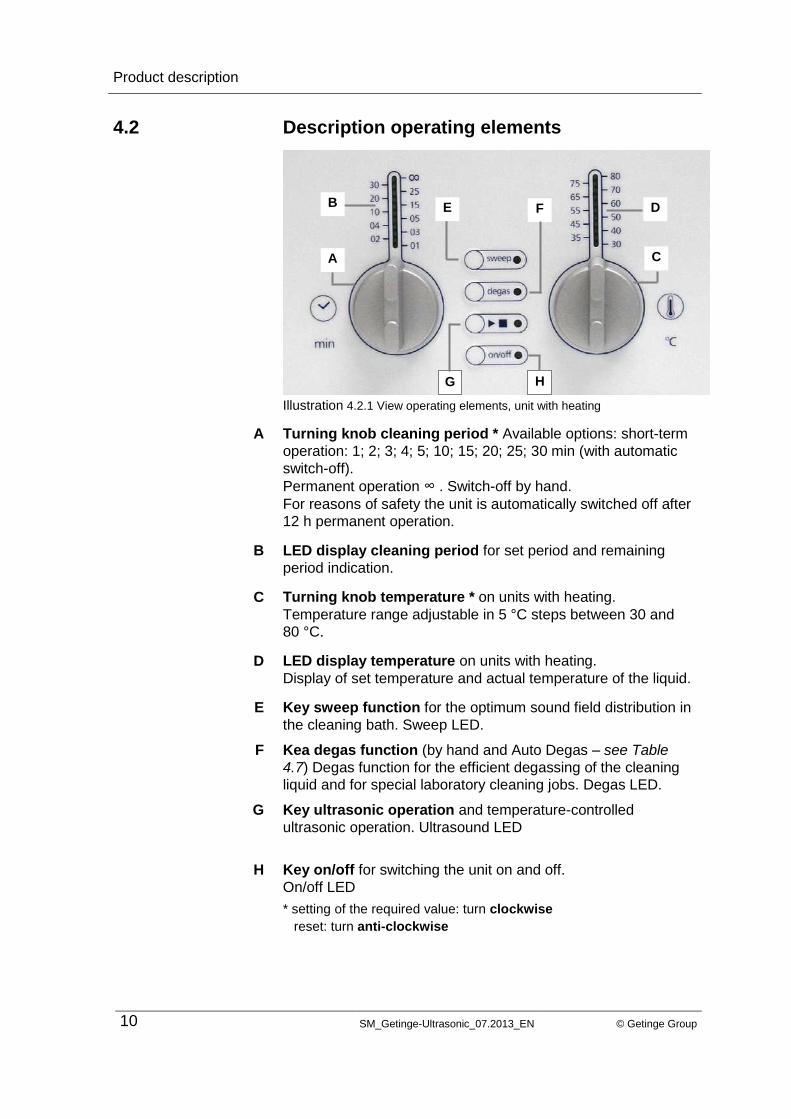
4.2 Description operating elements
Illustration 4.2.1 View operating elements, unit with heating
Turning knob cleaning period * Available options: short-term
operation: 1; 2; 3; 4; 5; 10; 15; 20; 25; 30 min (with automatic
switch-off).
Permanent operation ∞ . Switch-off by hand.
For reasons of safety the unit is automatically switched off after
12 h permanent operation.
LED display cleaning period for set period and remaining
period indication.
Turning knob temperature * on units with heating.
Temperature range adjustable in 5 °C steps between 30 and
80 °C.
LED display temperature on units with heating.
Display of set temperature and actual temperature of the liquid.
Key sweep function for the optimum sound field distribution in
the cleaning bath. Sweep LED.
Kea degas function (by hand and Auto Degas – see Table
4.7) Degas function for the efficient degassing of the cleaning
liquid and for special laboratory cleaning jobs. Degas LED.
Key ultrasonic operation and temperature-controlled
ultrasonic operation. Ultrasound LED
Key on/off for switching the unit on and off.
On/off LED
* setting of the required value: turn clockwise
reset: turn anti-clockwise
A
B
C
D
E
F
G
H
A
F
G
E B D
C
H

Product description
© Getinge Group SM_Getinge-Ultrasonic_07.2013_EN 11
4.3 Technical details
Mains voltage unit variants
(Vac)
Ultrasound
frequency (kHz)
Power consumpti
on total (W)
Ultrasonic power RMS
(W)
Ultrasonic maximum
peak power* (W)
Heating power (W)
30 100-120 | 220-240 37 280 80 320 200
40 100-120 | 220-240 37 340 140 560 200
60 100-120 | 220-240 37 550 150 600 400
70 100-120 | 220-240 37 750 150 600 600
80 100-120 | 220-240 37 750 150 600 600
90 100-120 | 220-240 37 550 150 600 400
100 100-120 | 220-240 37 550 150 600 400
120 100-120 | 220-240 37 1000 200 800 800
130 100-120 | 220-240 37 1100 300 1200 800
150 100-120 | 220-240 37 300 300 1200 -
180 100-120 | 220-240 37 1000 200 800 800
300 100-120 | 220-240 37 1500 300 1200 1200
*: Impulse sound; 30 – 300: Double half-wave sound. The form of signal has been adapted to the geometry of
the transducer tank. Depending on the form of signal the peak of the ultrasonic power is 4 or 8-fold.
Product description
12 SM_Getinge-Ultrasonic_07.2013_EN © Getinge Group
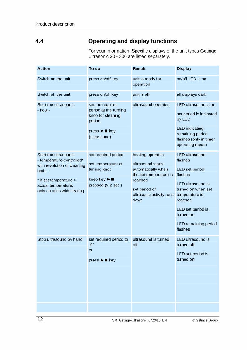
4.4 Operating and display functions
For your information: Specific displays of the unit types Getinge
Ultrasonic 30 - 300 are listed separately.
Action To do Result Display
Switch on the unit press on/off key unit is ready for
operation
on/off LED is on
Switch off the unit press on/off key unit is off all displays dark
Start the ultrasound
- now -
set the required
period at the turning
knob for cleaning
period
press ►■ key
(ultrasound)
ultrasound operates LED ultrasound is on
set period is indicated
by LED
LED indicating
remaining period
flashes (only in timer
operating mode)
Start the ultrasound
- temperature-controlled*;
with revolution of cleaning
bath –
* if set temperature >
actual temperature;
only on units with heating
set required period
set temperature at
turning knob
keep key ►■
pressed (> 2 sec.)
heating operates
ultrasound starts
automatically when
the set temperature is
reached
set period of
ultrasonic activity runs
down
LED ultrasound
flashes
LED set period
flashes
LED ultrasound is
turned on when set
temperature is
reached
LED set period is
turned on
LED remaining period
flashes
Stop ultrasound by hand set required period to
„0“
or
press ►■ key
ultrasound is turned
off
LED ultrasound is
turned off
LED set period is
turned on

Product description
© Getinge Group SM_Getinge-Ultrasonic_07.2013_EN 13
Action To do Result Display
Switch on heating*
*only on units with heating
set required
temperature
heating operates LED set temperature
is turned on
LED actual
temperature flashes
and moves towards
set temperature
When actual = set
temperature only the
LED set temperature
is on
When actual > set
temperature the LED
actual temperature
starts flashing again
Switch off heating by
hand
set temperature to „0“
position
heating switches off LED actual
temperature flashes
Switch on sweep function*
* Sweep and degas
cannot be operated at the
same time
set the required
period
press ►■ key
press Sweep key
ultrasound operates
in sweep mode
LED ultrasound is
turned on
LED sweep is turned
on
LED set temperature
is turned on
LED remaining period
flashes
Switch on degas function*
* Sweep and Degas
cannot be operated at the
same time
set the required
period
press ►■ key
press Degas key
ultrasound operates
in degas mode
LED degas is turned
on
LED ultrasound is
turned on
Getinge Ultrasonic
30 - 300: LED set
period is turned on
LED remaining period
flashes
Product description
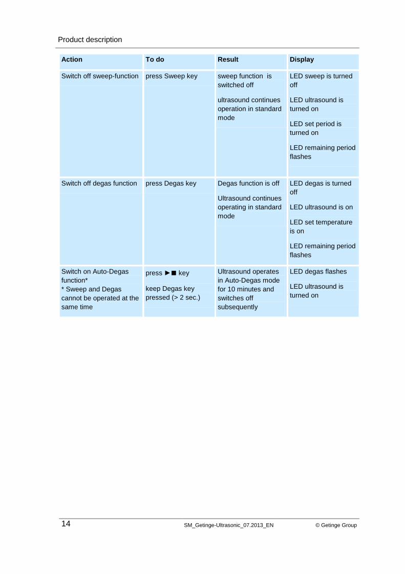
14 SM_Getinge-Ultrasonic_07.2013_EN © Getinge Group
Action To do Result Display
Switch off sweep-function press Sweep key sweep function is
switched off
ultrasound continues
operation in standard
mode
LED sweep is turned
off
LED ultrasound is
turned on
LED set period is
turned on
LED remaining period
flashes
Switch off degas function press Degas key Degas function is off
Ultrasound continues
operating in standard
mode
LED degas is turned
off
LED ultrasound is on
LED set temperature
is on
LED remaining period
flashes
Switch on Auto-Degas
function*
* Sweep and Degas
cannot be operated at the
same time
press ►■ key
keep Degas key
pressed (> 2 sec.)
Ultrasound operates
in Auto-Degas mode
for 10 minutes and
switches off
subsequently
LED degas flashes
LED ultrasound is
turned on
Product description
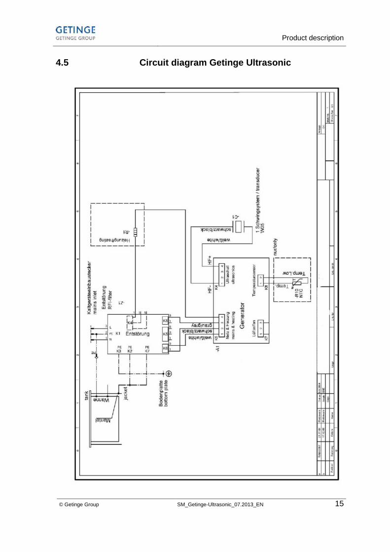
© Getinge Group SM_Getinge-Ultrasonic_07.2013_EN 15
4.5 Circuit diagram Getinge Ultrasonic

Trouble shooting / Table of malfunctions
16 SM_Getinge-Ultrasonic_07.2013_EN © Getinge Group
5 Trouble shooting / Table of malfunctions
Find out if the malfunction is caused by a fault on the unit or by
improper use. Examples for malfunctions due to improper use:
The cleaning result is not satisfactory:
The cleaning medium, the cleaning temperature or the
duration of the cleaning cycle are not suitable for the
cleaning task.
The cleaning result can also be impaired by a wrong or
insufficient filling level and/or very dirty cleaning liquid.
The unit does not heat up correctly:
For an efficient heating up of the cleaning liquid switch on
the ultrasound (see section 4.5. Start the ultrasound –
temperature-controlled*;with revolution of the cleaning bath)
and use a cover.
Check and find out if the fault is in the heating or in the
ultrasonic system.
Check housing and bottom plate of the unit for any visible
damage and check the tank for leaks before you connect the
unit to an interrupting transformer.
Then connect the unit to an adjustable interrupting transformer
for a functional check. You can easily and safely check the unit
for a short circuit by slowly adjusting the mains voltage upwards
and observing the current consumption. At the same time you
can find out which functions of the unit have broken down.
Various malfunctions are indicated by a flashing LED display:
Getinge Ultrasonic 30 - 300: LED display cleaning period
flashes fast („running light“) / LED display in the ultrasound key
flashes fast:
There is a fault on the PCB control, on the connection between
ultrasound >> transducer system or on the transducer system.
Getinge Ultrasonic 30 - 300: LED display heating temperature
flashes fast („running light“) / LED display in the ultrasound key
flashes fast:
There is a fault in the temperature measuring, e.g. interrupted
connection to temperature gauge or a faulty gauge.
Improper use
Faulty unit
LED display
malfunction
Ultrasound
malfunction
Temperature
malfunction
Trouble shooting / Table of malfunctions
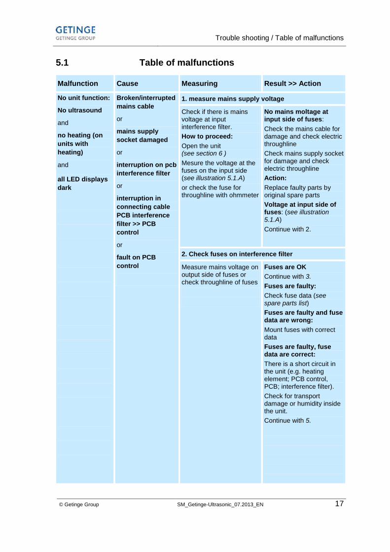
© Getinge Group SM_Getinge-Ultrasonic_07.2013_EN 17
5.1 Table of malfunctions
Malfunction Cause Measuring Result >> Action
No unit function:
No ultrasound
and
no heating (on
units with
heating)
and
all LED displays
dark
Broken/interrupted
mains cable
or
mains supply
socket damaged
or
interruption on pcb
interference filter
or
interruption in
connecting cable
PCB interference
filter >> PCB
control
or
fault on PCB
control
1. measure mains supply voltage
Check if there is mains voltage at input interference filter.
How to proceed:
Open the unit (see section 6 )
Mesure the voltage at the fuses on the input side (see illustration 5.1.A)
or check the fuse for throughline with ohmmeter
No mains moltage at input side of fuses:
Check the mains cable for damage and check electric throughline
Check mains supply socket for damage and check electric throughline
Action:
Replace faulty parts by original spare parts
Voltage at input side of fuses: (see illustration 5.1.A)
Continue with 2.
2. Check fuses on interference filter
Measure mains voltage on output side of fuses or check throughline of fuses
Fuses are OK
Continue with 3.
Fuses are faulty:
Check fuse data (see spare parts list)
Fuses are faulty and fuse data are wrong:
Mount fuses with correct data
Fuses are faulty, fuse data are correct:
There is a short circuit in the unit (e.g. heating element; PCB control, PCB; interference filter).
Check for transport damage or humidity inside the unit.
Continue with 5.
Trouble shooting / Table of malfunctions
18 SM_Getinge-Ultrasonic_07.2013_EN © Getinge Group
...
No unit function:
No ultrasound
and
no heating (on
units with
heating)
and
all LED displays
dark
Measuring Result >> Action
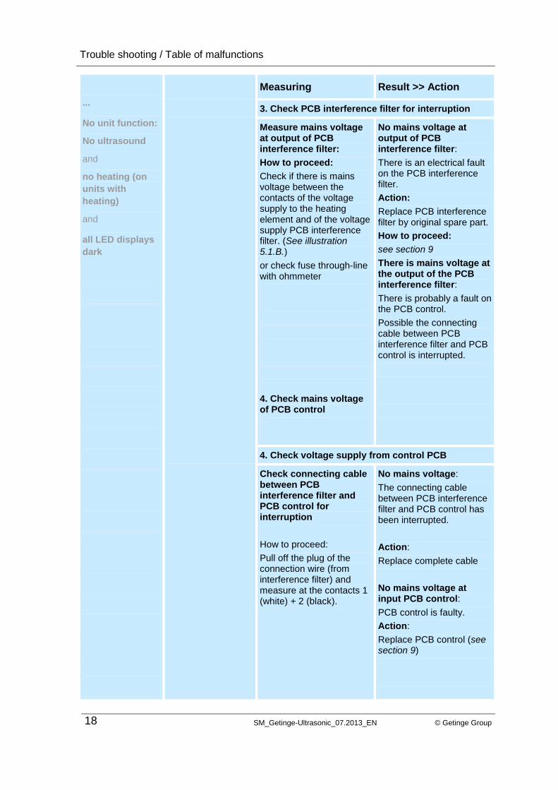
3. Check PCB interference filter for interruption
Measure mains voltage at output of PCB interference filter:
How to proceed:
Check if there is mains voltage between the contacts of the voltage supply to the heating element and of the voltage supply PCB interference filter. (See illustration 5.1.B.)
or check fuse through-line with ohmmeter
4. Check mains voltage of PCB control
No mains voltage at output of PCB interference filter:
There is an electrical fault on the PCB interference filter.
Action:
Replace PCB interference filter by original spare part.
How to proceed:
see section 9
There is mains voltage at the output of the PCB interference filter:
There is probably a fault on the PCB control.
Possible the connecting cable between PCB interference filter and PCB control is interrupted.
4. Check voltage supply from control PCB
Check connecting cable between PCB interference filter and PCB control for interruption
How to proceed:
Pull off the plug of the connection wire (from interference filter) and measure at the contacts 1 (white) + 2 (black).
No mains voltage:
The connecting cable between PCB interference filter and PCB control has been interrupted.
Action:
Replace complete cable
No mains voltage at input PCB control:
PCB control is faulty.
Action:
Replace PCB control (see section 9)

Trouble shooting / Table of malfunctions
© Getinge Group SM_Getinge-Ultrasonic_07.2013_EN 19
...
No unit function:
No ultrasound
and
no heating (on
units with
heating)
and
all LED displays
dark
Measuring Result >> Action
5. Check unit for short circuit (of fuses on PCB interference filter faulty, fuse data correct)
Probably there is a short circuit in the unit (PTC heating element; PCB control; PCB interference filter).
How to proceed:
The individual components must be checked separately.
6. check filter PCB for short circuit
How to proceed:
Check for scorchings / traces of water in the mains socket
Mount new fuses into PCB interference filter
Pull off the connecting cable between PCB interference elimination and PCB control, preferably at the PCB control.
Separate the supply wire from the PTC heating element at the respective plug contact on the PCB interference filter.
Connect the unit to the mains for testing purposes.
Fuses on PCB interference filter are blown again:
Short circuit on PCB interference filter. Replace interference filter (see section 9)
Fuses on PCB interference filter are not blown:
PCB interference filter is OK.
Short circuit is probably in PTC heating element or PCB control
Continue with 7.
7. Check heating element for short circuit
Separate the heating element from the mains
How to proceed:
Separate the supply wire from the heating element at the respective plug contacts on the interference filter.
Connect the unit to the mains.
Fuses on the interference filter are not blown:
Short circuit in the heating element. Replace the heating element (see section 13)
Fuses on the interference filter are blown:
Heating element is OK.
Probably short circuit in PCB control
Continue with 8
Trouble shooting / Table of malfunctions
20 SM_Getinge-Ultrasonic_07.2013_EN © Getinge Group
...
No unit function:
No ultrasound
and
no heating (on
units with
heating)
and
all LED displays
dark
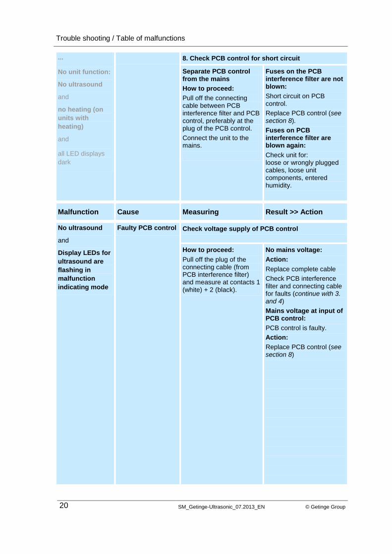
8. Check PCB control for short circuit
Separate PCB control from the mains
How to proceed:
Pull off the connecting cable between PCB interference filter and PCB control, preferably at the plug of the PCB control.
Connect the unit to the mains.
Fuses on the PCB interference filter are not blown:
Short circuit on PCB control.
Replace PCB control (see section 8).
Fuses on PCB interference filter are blown again:
Check unit for: loose or wrongly plugged cables, loose unit components, entered humidity.
Malfunction Cause Measuring Result >> Action
No ultrasound
and
Display LEDs for
ultrasound are
flashing in
malfunction
indicating mode
Faulty PCB control Check voltage supply of PCB control
How to proceed:
Pull off the plug of the connecting cable (from PCB interference filter) and measure at contacts 1 (white) + 2 (black).
No mains voltage:
Action:
Replace complete cable
Check PCB interference filter and connecting cable for faults (continue with 3. and 4)
Mains voltage at input of PCB control:
PCB control is faulty.
Action:
Replace PCB control (see section 8)
Trouble shooting / Table of malfunctions
© Getinge Group SM_Getinge-Ultrasonic_07.2013_EN 21
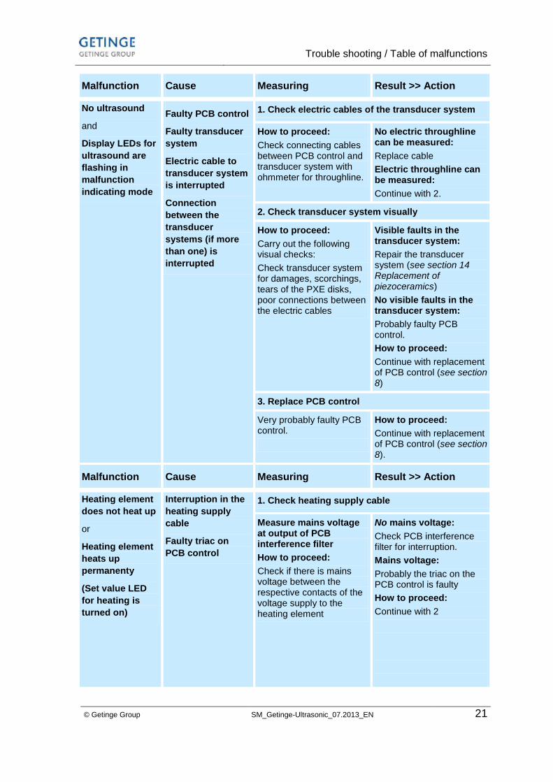
Malfunction Cause Measuring Result >> Action
No ultrasound
and
Display LEDs for
ultrasound are
flashing in
malfunction
indicating mode
Faulty PCB control
Faulty transducer
system
Electric cable to
transducer system
is interrupted
Connection
between the
transducer
systems (if more
than one) is
interrupted
1. Check electric cables of the transducer system
How to proceed:
Check connecting cables between PCB control and transducer system with ohmmeter for throughline.
No electric throughline can be measured:
Replace cable
Electric throughline can be measured:
Continue with 2.
2. Check transducer system visually
How to proceed:
Carry out the following visual checks:
Check transducer system for damages, scorchings, tears of the PXE disks, poor connections between the electric cables
Visible faults in the transducer system:
Repair the transducer system (see section 14 Replacement of piezoceramics)
No visible faults in the transducer system:
Probably faulty PCB control.
How to proceed:
Continue with replacement of PCB control (see section 8)
3. Replace PCB control
Very probably faulty PCB control.
How to proceed:
Continue with replacement of PCB control (see section 8).
Malfunction Cause Measuring Result >> Action
Heating element
does not heat up
or
Heating element
heats up
permanenty
(Set value LED
for heating is
turned on)
Interruption in the
heating supply
cable
Faulty triac on
PCB control
1. Check heating supply cable
Measure mains voltage at output of PCB interference filter
How to proceed:
Check if there is mains voltage between the respective contacts of the voltage supply to the heating element
No mains voltage:
Check PCB interference filter for interruption.
Mains voltage:
Probably the triac on the PCB control is faulty
How to proceed:
Continue with 2

Trouble shooting / Table of malfunctions
22 SM_Getinge-Ultrasonic_07.2013_EN © Getinge Group
2. Check triac on PCB control
How to proceed:
Check triac for short circuit with ohmmeter (see illustration 5.4.B)
Short circuit on triac
How to proceed:
Continue with replacement of PCB control (see section 8) or with repair of triac.
Heating does not
heat up
and
LEDs for heating
are flashing in
malfunction
indicating mode
Faulty temperature
sensor
Faulty supply
cable temperature
sensor
Check temperature sensor and supply cable
Measure resistance of the temperature sensor with ohmmeter:
At 25 °C approx. 10 kOhm
(see illustration 5.3.A)
Faulty temperature sensor:
If the measured resistance is not within this range the component is faulty.
How to proceed:
Continue with replacement of temperature sensor
Malfunction Cause Measuring Result >> Action
No unit function:
and
LED displys for
heating and
ultrasound are
flashing in
malfunction
indicating mode
Fault in the
programme
or
Faulty PCB control
Check PCB control
How to proceed:
Switch unit off and on again
Malfunction indication continues:
Continue with repalcement of PCB control (see section 8)
Unit function OK, no malfunction indicated:
Malfunction has been remedied
Illustration 5.2. Measuring points PCB interference filter
Measuring points
interference filter
Getinge Ultrasonic
30-300
A
B
C

Trouble shooting / Table of malfunctions
© Getinge Group SM_Getinge-Ultrasonic_07.2013_EN 23
Illustration 5.3. Measuring points PCB control
Measuring points temperature sensor. For measuring pull off
contact. At 25 °C approx. 10 kOhm
Measuring points triac (outside connections). At a measured
resistance below 100 Ohm the triac is faulty.
Illustration 5.4. Measuring points triac (here PCB control S10H)
Measuring points
PCB control
temperature sensor
A
B
A
A
How to open the unit
24 SM_Getinge-Ultrasonic_07.2013_EN © Getinge Group
6 How to open the unit
Live parts inside the unit.
Risk of electrocution!
Opening of the unit by authorized specialized staff only.
Always pull the mains plug before you open the unit.
For checks that require the unit to be connected use a mains interrupting transformer.
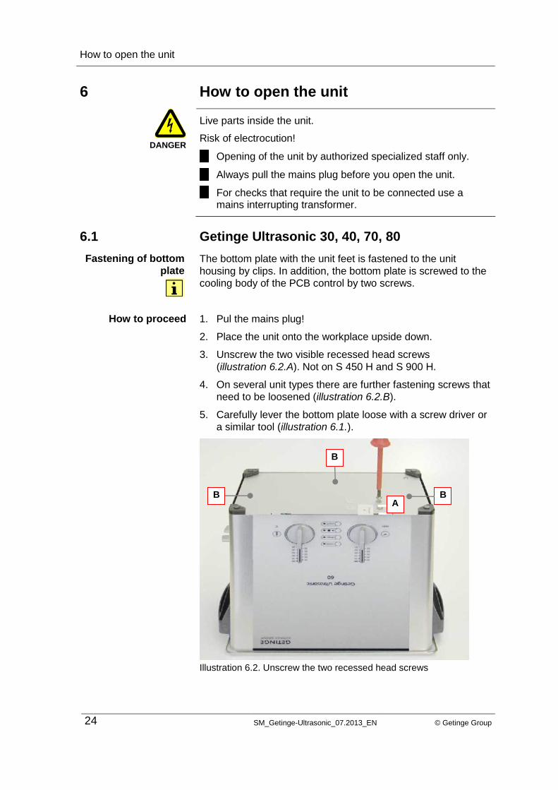
6.1 Getinge Ultrasonic 30, 40, 70, 80
The bottom plate with the unit feet is fastened to the unit
housing by clips. In addition, the bottom plate is screwed to the
cooling body of the PCB control by two screws.
1. Pul the mains plug!
2. Place the unit onto the workplace upside down.
3. Unscrew the two visible recessed head screws
(illustration 6.2.A). Not on S 450 H and S 900 H.
4. On several unit types there are further fastening screws that
need to be loosened (illustration 6.2.B).
5. Carefully lever the bottom plate loose with a screw driver or
a similar tool (illustration 6.1.).
Illustration 6.2. Unscrew the two recessed head screws
DANGER
Fastening of bottom
plate
How to proceed
A
B
B B

How to open the unit
© Getinge Group SM_Getinge-Ultrasonic_07.2013_EN 25
6.2 Getinge Ultrasonic 60, 100 – 300
The bottom plate is screwed to the unit through the unit feet. In
addition, the bottom plate is screwed to the cooling body of the
PCB control with 2 screws.
1. Pull the mains plug!
2. Place the unit onto the workplace upside down.
3. Unscrew the 4 unit feet.
4. Unscrew the two visible recessed head screws.
5. Carefully lever the bottom plate loose with a screw driver or
a similar tool illustration 6.1.).
Ilustration 6.3. Unscrew the two recessed head screws and the 4 unit
feet
6.3 How to close the unit /
How to mount the bottom plate
Follow the instructions on opening the unit in reverse order.
Ensure that all electric wires are connected correctly and no
electric wires are pinched by the bottom plate before you close
the unit.
Fastening of bottom
plate
How to proceed
2x
4x

How to remove / replace the turning knobs
26 SM_Getinge-Ultrasonic_07.2013_EN © Getinge Group
7 How to remove / replace the turning knobs
The turning knobs are plugged onto the unit front. The turning
knobs are connected to the relevant potentiometer on the PCB
control by a shaft.
7.1 How to remove the turning knobs
There are two ways to remove the turning knobs:
This method is useful if only the turning knobs are to be
replaced. However, when pulling the turning knobs off, it is
possible that the shaft (illustration. 7.2.A.) slides out of the shell
of the turning knob (illustration 7.4.B.) and remains connected
to the potentiometer on the PCB control. If this happens the
shaft can be pulled out with pliers or side nippers.
Pull off the turning knob exactly square to the unit.
Illustration 7.1. Pull off the turning knob
Illustration 7.2. View turning knob
Fastening
Without opening the
unit
How to proceed
A
B

How to remove / replace the turning knobs
© Getinge Group SM_Getinge-Ultrasonic_07.2013_EN 27
This method is useful if the unit must be opened anyway, e.g.
for repair purposes (exchange of PCB control).
1. Pull the mains plug!
2. Open the unit as described in section 6.
3. Push the shaft of the turning knob out from inside (A) and
pull the knob off from outside at the same time (B).
Illustration 7.3. Pull off the turning knob with opened unit.
7.2 How to mount the turning knobs
Put the turning knob square onto the unit. Ensure that the
turning knob is positioned correctly: The cog of the turning knob
(A) must correspond with the stop position on the PCB support
(B).
With opening the unit
Proceed as follows
How to proceed
A
B

How to replace the PCB control
28 SM_Getinge-Ultrasonic_07.2013_EN © Getinge Group
Illustration 7.4. Put on the turning knob
8 How to replace the PCB control
The PCB control is clipped into the unit. It can be removed
without any tool.
Some of the electronic components on the PCB control are
sensitive against electrostatic charging. These charges may
destroy the component. Therefore, for the correct handling of
the PCB control please observe the instructions on ESD
protection (section 1.4).
8.1 Electric connections
Illustration 8.1. Connections PCB control
NOTE
A B
A
D
C
B
How to replace the PCB control
© Getinge Group SM_Getinge-Ultrasonic_07.2013_EN 29
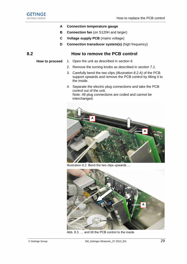
Connection temperature gauge
Connection fan (on S120H and larger)
Voltage supply PCB (mains voltage)
Connection transducer system(s) (high frequency)
8.2 How to remove the PCB control
1. Open the unit as described in section 6.
2. Remove the turning knobs as described in section 7.1.
3. Carefully bend the two clips (illustration 8.2.A) of the PCB support upwards and remove the PCB control by tilting it to the inside.
4. Separate the electric plug connections and take the PCB control out of the unit. Note: All plug connections are coded and cannot be interchanged.
Illustration 8.2. Bend the two clips upwards …
Abb. 8.3. … and tilt the PCB control to the inside
A
B
C
D
How to proceed
A
A
A
How to replace the PCB control
30 SM_Getinge-Ultrasonic_07.2013_EN © Getinge Group
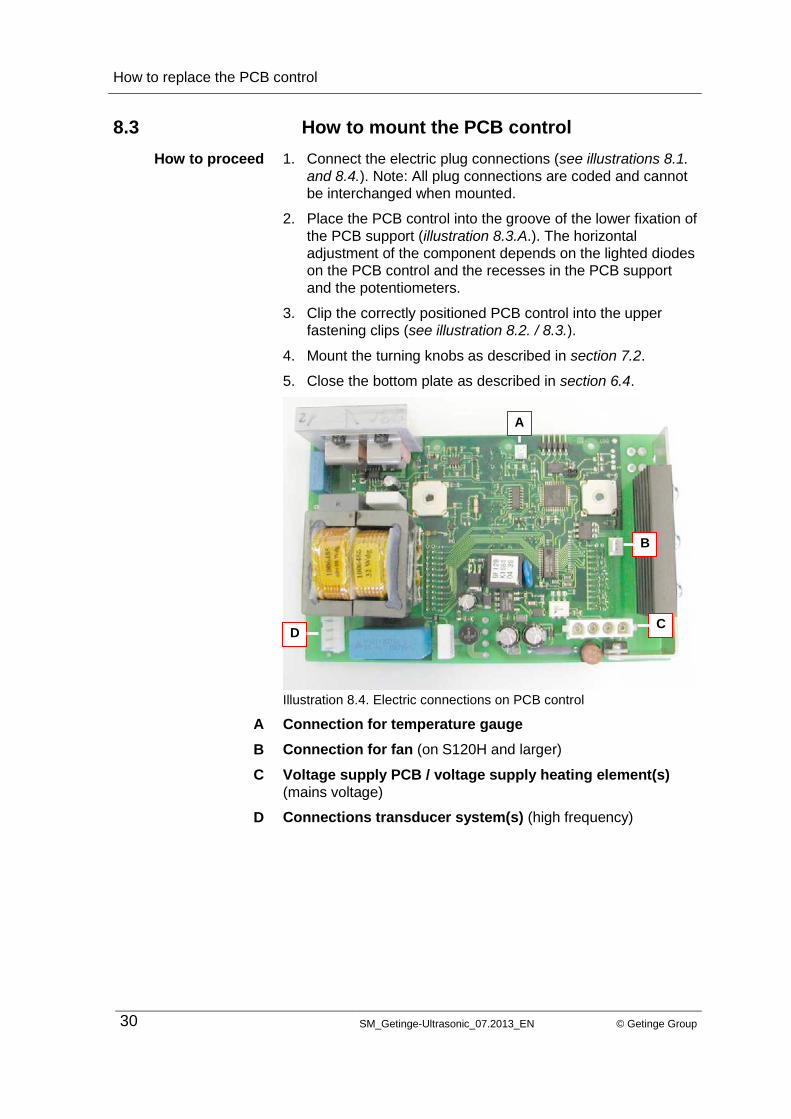
8.3 How to mount the PCB control
1. Connect the electric plug connections (see illustrations 8.1.
and 8.4.). Note: All plug connections are coded and cannot
be interchanged when mounted.
2. Place the PCB control into the groove of the lower fixation of
the PCB support (illustration 8.3.A.). The horizontal
adjustment of the component depends on the lighted diodes
on the PCB control and the recesses in the PCB support
and the potentiometers.
3. Clip the correctly positioned PCB control into the upper
fastening clips (see illustration 8.2. / 8.3.).
4. Mount the turning knobs as described in section 7.2.
5. Close the bottom plate as described in section 6.4.
Illustration 8.4. Electric connections on PCB control
Connection for temperature gauge
Connection for fan (on S120H and larger)
Voltage supply PCB / voltage supply heating element(s)
(mains voltage)
Connections transducer system(s) (high frequency)
How to proceed
A
B
C
D
C
B
D
A
How to replace the PCB interference filter
© Getinge Group SM_Getinge-Ultrasonic_07.2013_EN 31
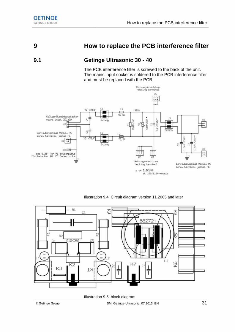
9 How to replace the PCB interference filter
9.1 Getinge Ultrasonic 30 - 40
The PCB interference filter is screwed to the back of the unit.
The mains input socket is soldered to the PCB interference filter
and must be replaced with the PCB.
Illustration 9.4. Circuit diagram version 11.2005 and later
Illustration 9.5. block diagram

How to replace the PCB interference filter
32 SM_Getinge-Ultrasonic_07.2013_EN © Getinge Group
9.1.1 How to remove the PCB interference filter
Illustration 9.6. Fastening of the PCB interference filter
1. Open the unit as described in section 6.
2. Mark the electric plug connections (to avoid interchanging
when they are reconnected) and loosen them.
3. Pull both two-part plastic pins (illustration 9.6.A) that arrest
the mains input socket. For this, lever the pins out of the
housing, e.g. with a knife (illustration 9.7.A).
4. Unscrew the two screws (illustration 9.6.B) that fasten the
PCB interference filter to the back of the unit.
5. Take the PCB interference filter out of the unit.
Illustration 9.7. Removal of the plastic pins
How to proceed
B
A
C
A A
How to replace the PCB interference filter
© Getinge Group SM_Getinge-Ultrasonic_07.2013_EN 33
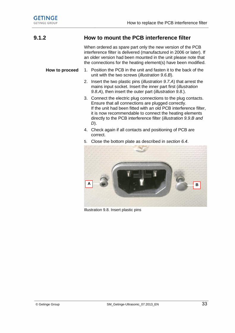
9.1.2 How to mount the PCB interference filter
When ordered as spare part only the new version of the PCB
interference filter is delivered (manufactured in 2006 or later). If
an older version had been mounted in the unit please note that
the connections for the heating element(s) have been modified.
1. Position the PCB in the unit and fasten it to the back of the unit with the two screws (illustration 9.6.B).
2. Insert the two plastic pins (illustration 9.7.A) that arrest the mains input socket. Insert the inner part first (illustration 9.8.A), then insert the outer part (illustration 9.8.).
3. Connect the electric plug connections to the plug contacts. Ensure that all connections are plugged correctly. If the unit had been fitted with an old PCB interference filter, it is now recommendable to connect the heating elements directly to the PCB interference filter (illustration 9.9.B and D).
4. Check again if all contacts and positioning of PCB are correct.
5. Close the bottom plate as described in section 6.4.
Illustration 9.8. Insert plastic pins
How to proceed
A B
How to replace the PCB interference filter
34 SM_Getinge-Ultrasonic_07.2013_EN © Getinge Group
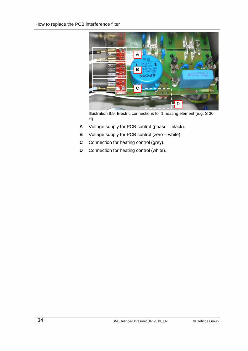
Illustration 9.9. Electric connections for 1 heating element (e.g. S 30
H)
Voltage supply for PCB control (phase – black).
Voltage supply for PCB control (zero – white).
Connection for heating control (grey).
Connection for heating control (white).
A
B
C
D
A
B
C
D

How to replace the PCB interference filter
© Getinge Group SM_Getinge-Ultrasonic_07.2013_EN 35
9.2 Getinge Ultrasonic 60 - 100
The PCB interference filter is screwed to the back of the unit.
The mains input socket is soldered to the PCB interference filter
and must be replaced with the PCB.
Illustration 9.13 Circuit diagram version of 11.2005 or later
Illustration 9.14. block diagram

How to replace the PCB interference filter
36 SM_Getinge-Ultrasonic_07.2013_EN © Getinge Group
9.2.1 How to remove the PCB interference filtern
Illustration 9.15. Fastening of PCB interference filter
1. Open the unit as described in section 6.
2. Mark the electric plug connections (to avoid interchanging
when they are reconnected) and loosen them.
3. Pull both two-part plastic pins (illustration 9.15.A) that arrest
the mains input socket. For this, lever the pins out of the
housing, e.g. with a knife (illustration 9.16.A).
4. Unscrew the two screws (illustration 9.15.B) that fasten the
PCB interference filter to the back of the unit.
5. Take the PCB interference filter out of the unit.
Illustration 9.16. Removal of the plastic pins
How to proceed
B
A
C
A A
How to replace the PCB interference filter
© Getinge Group SM_Getinge-Ultrasonic_07.2013_EN 37
9.2.2 How to mount the PCB interference filter
When ordered as spare part only the new version of the PCB
interference filter is delivered (manufactured in 2006 or later). If
an older version had been mounted in the unit please note that
the connections for the heating element(s) have been modified.
1. Position the PCB in the unit and fasten it to the back of the unit with the two screws (illustration 9.15. B).
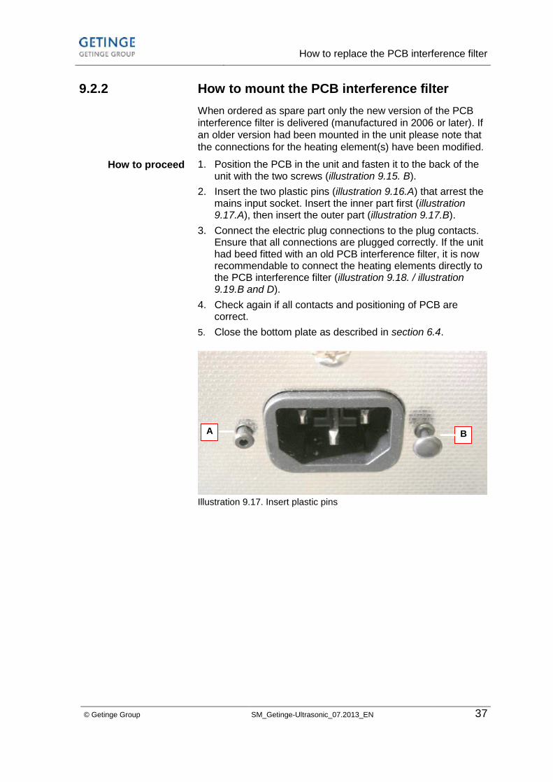
2. Insert the two plastic pins (illustration 9.16.A) that arrest the mains input socket. Insert the inner part first (illustration 9.17.A), then insert the outer part (illustration 9.17.B).
3. Connect the electric plug connections to the plug contacts. Ensure that all connections are plugged correctly. If the unit had beed fitted with an old PCB interference filter, it is now recommendable to connect the heating elements directly to the PCB interference filter (illustration 9.18. / illustration 9.19.B and D).
4. Check again if all contacts and positioning of PCB are correct.
5. Close the bottom plate as described in section 6.4.
Illustration 9.17. Insert plastic pins
How to proceed
A B
How to replace the PCB interference filter
38 SM_Getinge-Ultrasonic_07.2013_EN © Getinge Group
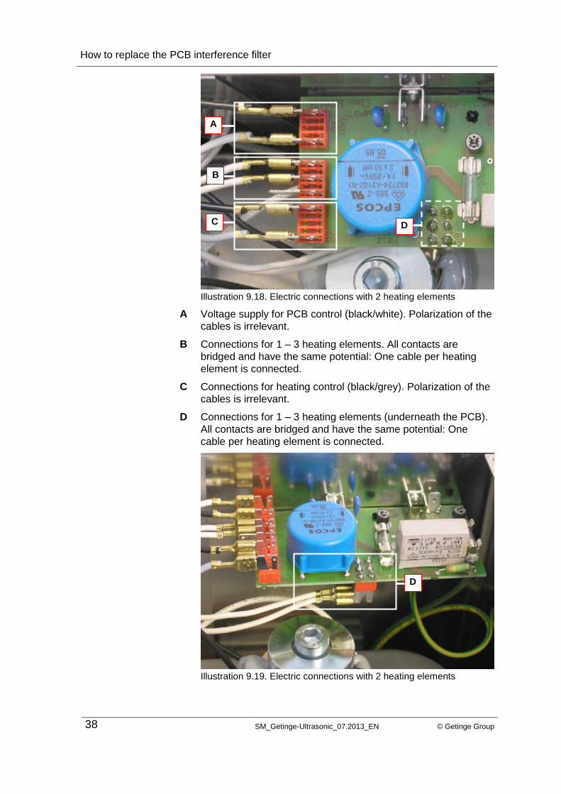
Illustration 9.18. Electric connections with 2 heating elements
Voltage supply for PCB control (black/white). Polarization of the
cables is irrelevant.
Connections for 1 – 3 heating elements. All contacts are
bridged and have the same potential: One cable per heating
element is connected.
Connections for heating control (black/grey). Polarization of the
cables is irrelevant.
Connections for 1 – 3 heating elements (underneath the PCB).
All contacts are bridged and have the same potential: One
cable per heating element is connected.
Illustration 9.19. Electric connections with 2 heating elements
A
B
C
D
A
B
C D
D
How to replace the PCB interference filter
© Getinge Group SM_Getinge-Ultrasonic_07.2013_EN 39
9.3 Getinge Ultrasonic 120 - 300
The PCB interference filter is screwed to the back of the unit.
The mains input socket is soldered to the PCB interference filter
and must be replaced with the PCB.
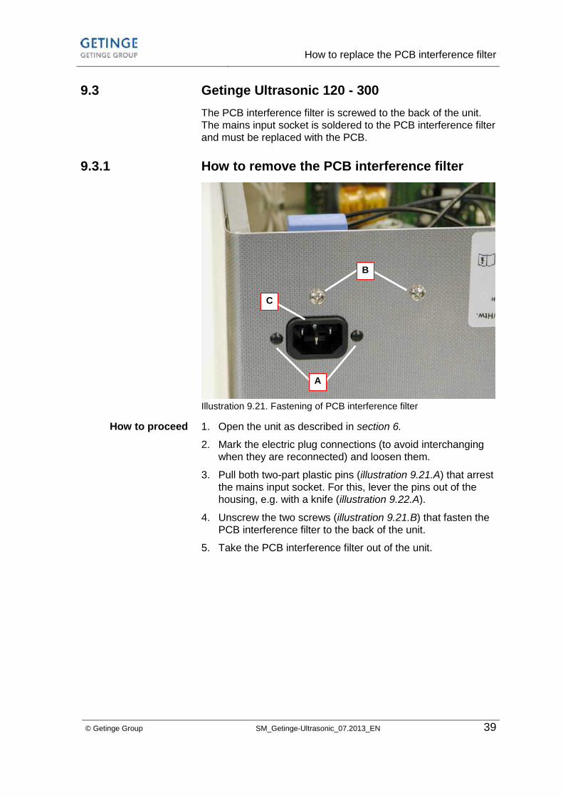
9.3.1 How to remove the PCB interference filter
Illustration 9.21. Fastening of PCB interference filter
1. Open the unit as described in section 6.
2. Mark the electric plug connections (to avoid interchanging
when they are reconnected) and loosen them.
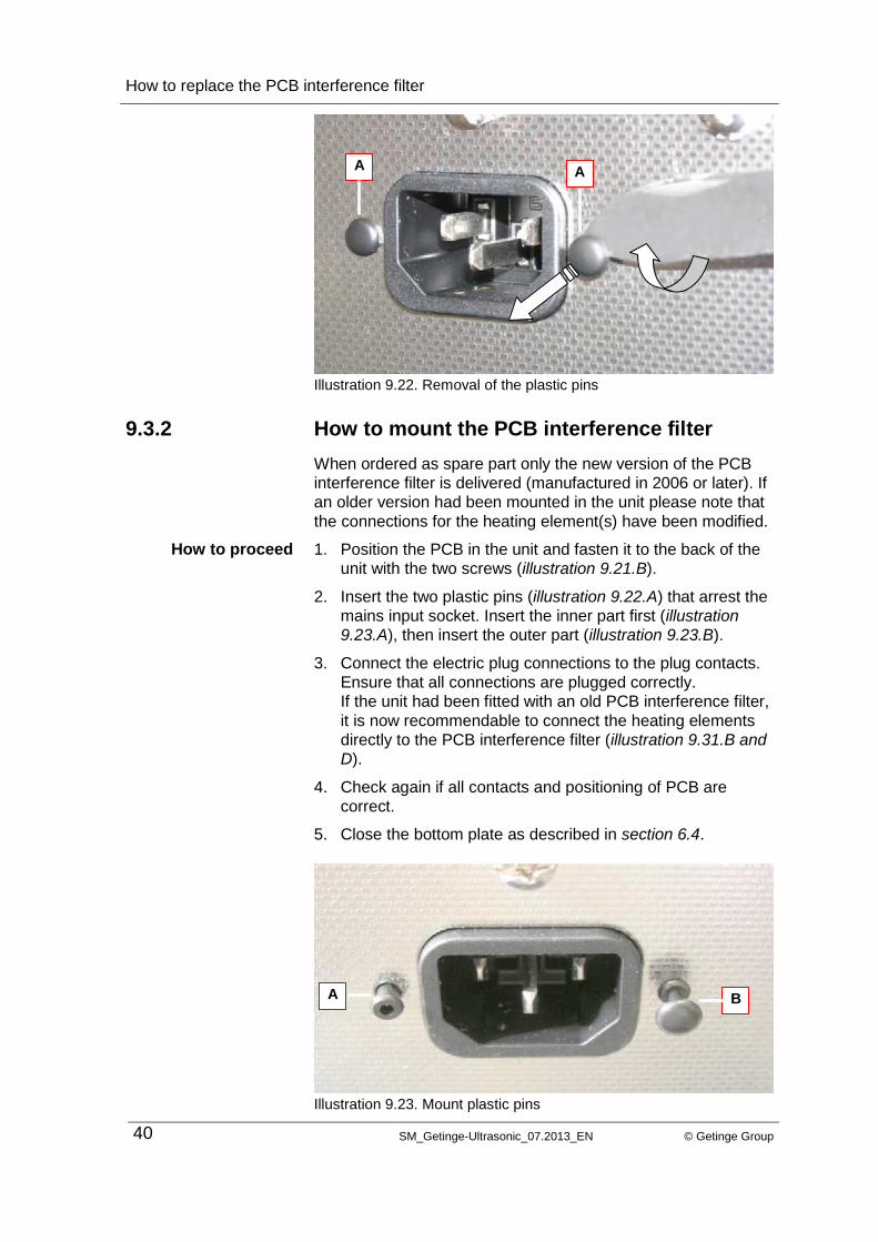
3. Pull both two-part plastic pins (illustration 9.21.A) that arrest
the mains input socket. For this, lever the pins out of the
housing, e.g. with a knife (illustration 9.22.A).
4. Unscrew the two screws (illustration 9.21.B) that fasten the
PCB interference filter to the back of the unit.
5. Take the PCB interference filter out of the unit.
How to proceed
B
A
C
How to replace the PCB interference filter
40 SM_Getinge-Ultrasonic_07.2013_EN © Getinge Group
Illustration 9.22. Removal of the plastic pins
9.3.2 How to mount the PCB interference filter
When ordered as spare part only the new version of the PCB
interference filter is delivered (manufactured in 2006 or later). If
an older version had been mounted in the unit please note that
the connections for the heating element(s) have been modified.
1. Position the PCB in the unit and fasten it to the back of the
unit with the two screws (illustration 9.21.B).
2. Insert the two plastic pins (illustration 9.22.A) that arrest the
mains input socket. Insert the inner part first (illustration
9.23.A), then insert the outer part (illustration 9.23.B).
3. Connect the electric plug connections to the plug contacts.
Ensure that all connections are plugged correctly.
If the unit had been fitted with an old PCB interference filter,
it is now recommendable to connect the heating elements
directly to the PCB interference filter (illustration 9.31.B and
D).
4. Check again if all contacts and positioning of PCB are
correct.
5. Close the bottom plate as described in section 6.4.
Illustration 9.23. Mount plastic pins
How to proceed
A A
A B
How to replace the PCB interference filter
© Getinge Group SM_Getinge-Ultrasonic_07.2013_EN 41
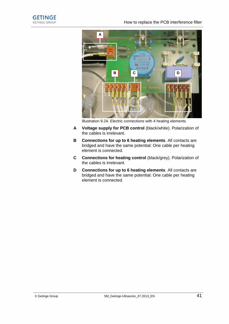
Illustration 9.24. Electric connections with 4 heating elements
Voltage supply for PCB control (black/white). Polarization of
the cables is irrelevant.
Connections for up to 6 heating elements. All contacts are
bridged and have the same potential: One cable per heating
element is connected.
Connections for heating control (black/grey). Polarization of
the cables is irrelevant.
Connections for up to 6 heating elements. All contacts are
bridged and have the same potential: One cable per heating
element is connected.
A
B
C
D
A
B C D
How to replace the potentiometer for the
cleaning period / for temperature
42 SM_Getinge-Ultrasonic_07.2013_EN © Getinge Group
10 How to replace the potentiometer for the
cleaning period / for temperature
Setting of the cleaning period and the temperature is carried out
via potentiometer which are soldered to the PCB control.
A breakdown can be caused by heavy mechanical forces such
as shock or transport damages.
To replace the component it is necessary to open the bottom
plate and to take out the PCB control. Proceed as follows:
1. Open the unit as described in section 6.
2. Pull off the turning knob as described in section 7.
3. Remove the PCB control as described in section 7.
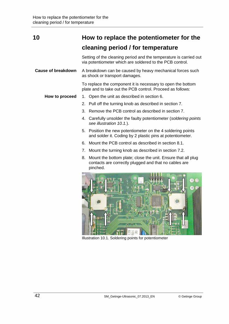
4. Carefully unsolder the faulty potentiometer (soldering points
see illustration 10.1.).
5. Position the new potentiometer on the 4 soldering points
and solder it. Coding by 2 plastic pins at potentiometer.
6. Mount the PCB control as described in section 8.1.
7. Mount the turning knob as described in section 7.2.
8. Mount the bottom plate; close the unit. Ensure that all plug
contacts are correctly plugged and that no cables are
pinched.
Illustration 10.1. Soldering points for potentiometer
Cause of breakdown
How to proceed
How to replace the front panel
© Getinge Group SM_Getinge-Ultrasonic_07.2013_EN 43
11 How to replace the front panel
The front panel consists of adhesive foil. There is no further
adhesive necessary.
The unit does not require to be opened.
To replace the front panel proceed as follows:
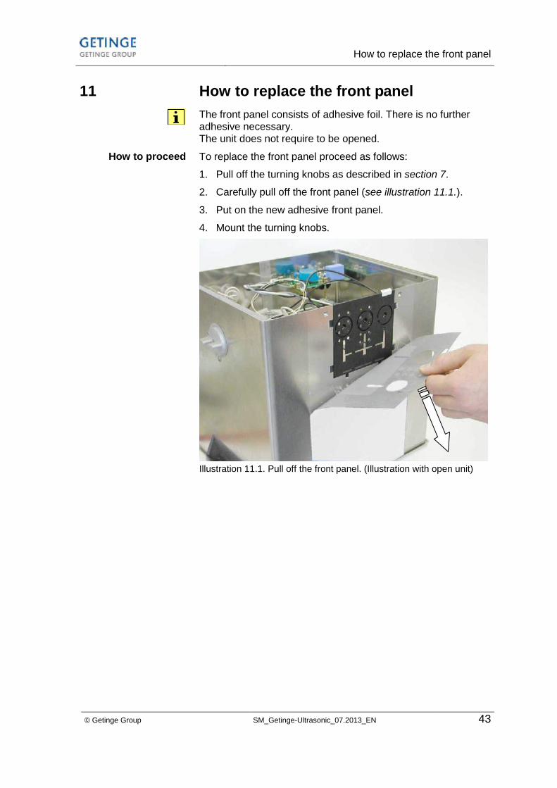
1. Pull off the turning knobs as described in section 7.
2. Carefully pull off the front panel (see illustration 11.1.).
3. Put on the new adhesive front panel.
4. Mount the turning knobs.
Illustration 11.1. Pull off the front panel. (Illustration with open unit)
How to proceed
How to replace the PCB support
44 SM_Getinge-Ultrasonic_07.2013_EN © Getinge Group
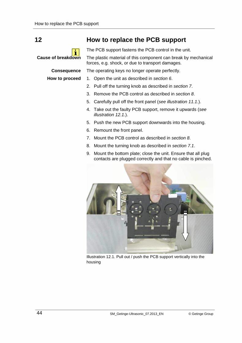
12 How to replace the PCB support
The PCB support fastens the PCB control in the unit.
The plastic material of this component can break by mechanical
forces, e.g. shock, or due to transport damages.
The operating keys no longer operate perfectly.
1. Open the unit as described in section 6.
2. Pull off the turning knob as described in section 7.
3. Remove the PCB control as described in section 8.
5. Carefully pull off the front panel (see illustration 11.1.).
4. Take out the faulty PCB support, remove it upwards (see
illustration 12.1.).
5. Push the new PCB support downwards into the housing.
6. Remount the front panel.
7. Mount the PCB control as described in section 8.
8. Mount the turning knob as described in section 7.1.
9. Mount the bottom plate; close the unit. Ensure that all plug
contacts are plugged correctly and that no cable is pinched.
Illustration 12.1. Pull out / push the PCB support vertically into the
housing
Cause of breakdown
Consequence
How to proceed
How to replace the heating
© Getinge Group SM_Getinge-Ultrasonic_07.2013_EN 45
13 How to replace the heating
The PTC heating element is safe to run dry. If the level of the
liquid falls below the position of the heating element, it
automatically reduces the current consumption and thereby
reduces the heating energy.
The performance of the heating element does not change
during its service life. The only possible cause of a breakdown
of this type of heating is a short circuit in the component
(humidity, faulty insulation, etc.)
No function:
In most cases the fault current breaker or the fuse automatic of
the relevant socket is released.
The fuses on the interference filter are faulty.
The aluminum casing of the heating element is pushed into to
supporting rails and secured against displacement with silicone.
On many units the heating element can be replaced without
removal of the transducer tank tank.
Exceptions: Getinge Ultrasonic 60, 100, 120, 180; 300. On
these units the transducer tank must be removed first as
described in section 15.
On all other units proceed as follows:
1. Open the unit as described in section 6.
2. Find the faulty heating elements (if there are more than one heating element), e.g. by separately connecting the individual heating elements to the voltage supply. Caution: in addition to the electric supply cable to the heating element, the earthing must be provided.
3. Loosen the connecting cables from the faulty heating element.
4. Cut the silicone fixation (which secures the heating element against displacement) in the area between the support rails and the heating element see illustration 13.1.A / 13.2.A / 13.3.A.
5. Push the aluminum profile of the heating element horizontally out of the guiding rails, e.g. with a large fork wrench, a wood block, etc. and a plastic hammer.
6. Use a file to round off the two edges of the aluminum profile of the new heating element where it will enter the supporting rails.
7. Carefully push the heating element into the supporting rails.
8. Secure the heating element against displacement with silicone.
Cause of breakdown
Consequence
Exchange of
component
How to proceed

How to replace the heating
46 SM_Getinge-Ultrasonic_07.2013_EN © Getinge Group
Illustration 13.1. Transducer tank removed, with horizontally mounted
heating element. Broken lines: cut the silicone fixation (A). Push the
heating element out of the support rails as indicated by the arrows.
Cut the silicone fixation (A) with a knife.
Push the heating element in direction (B) out of the supporting
rails.
Prepare the new heating element: The new heating element
can be pushed in more easily if the edges of the aluminum
profile have been rounded off with a file.
Insert the new heating element (position C) into the supporting
rails. Push it into the supporting rails, be careful not to jam the
heating element. Then secure against displacement with
silicone.
Illustration 13.2. Transducer tank unremoved, with horizontally
mounted heating element. Broken line: cut the silicone to remove.
Removed tank
Getinge Ultrasonic
30-300
A
B
B
Tank unremoved
Getinge Ultrasonic
30-300
B
C A
B
C A

Replacement of piezoceramics
© Getinge Group SM_Getinge-Ultrasonic_07.2013_EN 47
14 Replacement of piezoceramics
The piezoceramics must be replaced if one or more of the disks
are torn or damaged by scorching.
The transducer system should be opened only when all other
possible causes of a malfunction have been checked and if
both the know-how and the required tools are available.
The piezoceramics are selected capacitively in each unit and
are mounted in full sets only. This means that all piezoceramics
in one transducer system must show the exact electric
behaviour in order to guarantee a homogeneous ultrasonic
performance of the transducer system. The consequence of an
asymmetric charge of the transducer systems would be a
higher risk of breakdown and an increased cavitational erosion
on one side of the tank. (This does not apply to units with a
single transducer system.)
Therefore, all transducer disks should be replaced even if only
individual piezoceramics are faulty. Getinge deliver preselected
sets of piezoceramics.
Piezoceramics can be damaged for different reasons (mostly
tears): e.g. by heavy cleaning items put directly onto the tank
floor, excessive bath temperatures with intensive ultrasonic
operation (> 85 °C).
High relative humidity of air or liquid inside can cause
scorchings on and inside the transducer system.
Illustration 14.1. Torn and broken piezoceramics
In some cases torn disks or scorchings can be visible without
opening the unit. However, to make sure it is necessary to open
and examine the piezoceramics and the insulating duct.
Cause of breakdown
Trouble shooting

Replacement of piezoceramics
48 SM_Getinge-Ultrasonic_07.2013_EN © Getinge Group
It is possible that torn piezoceramics remain undetected,
because output, transducer performance and current diagram
are normal.
To carry out this repair work a torque wrench is indispensable!
Caution! Risk of electrocution due to high amount of electricity
on the piezoceramics!
The piezoceramic is charged with a high amount of electricity
when the transducer system is opened or tightened. This can
be branched off by short circuiting between two terminal lugs,
e.g. with a screw driver. For the same reason, also short circuit
the plug contacts of the electric cables of the transducer
system.
The electric charge is also built up by temperature changes,
e.g. cooling of a piezoceramic.
Do not touch charged piezoceramics!
Replace faulty piezoceramics as follows:
1. Place the unit upside down on a solid surface and secure it
against displacement (e.g. with screw clamps and wood
ledges).
2. Open the unit as described in section 6.
3. Open the transducer system screw(s) with the torque
wrench. Caution! Do not tear the transducer system by jamming the
torque wrench.
The torque wrench must be held vertically to the transducer
system during the complete process of unscrewing. The
power given to the handle of the tool must be exactly
countered by the hand that centers the tool (see illustration
14.2.).
4. Check each transducer disk for hair cracks and scorchings,
check the insulating sleeves for scorchings. Always
exchange the aluminum washers when you open the
system.
Tool
Electric load
How to open the
transducer system

Replacement of piezoceramics
© Getinge Group SM_Getinge-Ultrasonic_07.2013_EN 49
For assembly of the transducer system ensure that all contact
surfaces are clean.
The transducer disks mus be poled correctly. Observe the
markings on the piezoceramics see illustration 14.3. and 14.4.:
The marking must always point to the plus connection of the
transducer system.
1. Put a drop of Loctite or similar onto the thread of the
coupling piece (to lock the screw).
2. Assemble the individual parts of the transducer system
exactly as shown in the illustration.
3. Important! The black markings must point to the plus
terminal lug.
4. Screw in the transducer system screw and fix it with the
torque wrench. Systems with 1 piezoceramic (E35) at 46 Nm.
Systems with 2 piezoceramics (W35) at 58 Nm.
Caution: The transducer disk is charged with electricity
when the transducer system screw is tightened. Branch off
the electric charge by short circuiting between two terminal
lugs, e.g. with a screw driver.
Illustration 14.2. Always hold the torque wrench vertically. Do not tilt
the tool!
How to assemble the
transducer system

Replacement of piezoceramics
50 SM_Getinge-Ultrasonic_07.2013_EN © Getinge Group
Illustration 14.4. Transducer system with 2 piezoceramics
Pressure piece
Terminal lug minus connection
Piezoceramic
Terminal lug plus connection
Aluminum washer
Aluminum coupling piece
Insulating disk
Structure of
transducer system
with 2 piezoceramics
(W 35)
A
B
C
D
E
F
G
A
E
F
C
B
E
D

Replacement of piezoceramics
© Getinge Group SM_Getinge-Ultrasonic_07.2013_EN 51
W 35 E 35
Fig 7
transducer system scew
pressure piece
insulating duct
terminal lug "-"
insulat. disk
terminal lug "+"
PXE transducer disk
aluminum washer
coupling piece
PXE transducer disk
aluminum washer
M8 M10
Illustration 14.5.
on the left: structure of transducer system with 2 piezoceramics
on the right: structure of transducer system with 1 piezoceramic
M 10 M 8
Replacement of transducer tank
52 SM_Getinge-Ultrasonic_07.2013_EN © Getinge Group
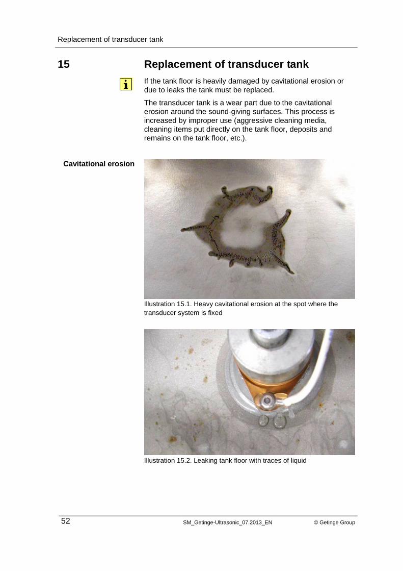
15 Replacement of transducer tank
If the tank floor is heavily damaged by cavitational erosion or
due to leaks the tank must be replaced.
The transducer tank is a wear part due to the cavitational
erosion around the sound-giving surfaces. This process is
increased by improper use (aggressive cleaning media,
cleaning items put directly on the tank floor, deposits and
remains on the tank floor, etc.).
Illustration 15.1. Heavy cavitational erosion at the spot where the
transducer system is fixed
Illustration 15.2. Leaking tank floor with traces of liquid
Cavitational erosion
Replacement of transducer tank
© Getinge Group SM_Getinge-Ultrasonic_07.2013_EN 53
There are two ways to replace the transducer tank:
Replacement by a complete transducer tank with mounted
transducer system (and heating, if required). We recommend to
use a complete tank if the transducer system is damaged and if
you do not have the necessary know-how for a replacement of
piezoceramics.
Replacement by a preassembled tank with coupling piece(s)
and the support for the heating element(s), but without
transducer system. We recommend to use the preassembled
tank if the transducer system on the old tank is without fault and
can be mounted on the new tank. For this you need a torque
wrench. We recommend to carry out this repair only if you have
the required know-how for replacing piezoceramics.
For instructions on the replacement of the transducer system
and / or of the piezoceramics please see section 14.
1. Place the unit upside down on a solid workplace.
2. Open the unit as described in section 6.
3. On units with heating: Interrupt the electric supply cables to
the heating(s) and separate the temperature sensor from
the unit.
Caution! Mark all electric cables to avoid interchanging
when you assemble the unit: risk of damage.
4. On units with drain duct: Loosen the screw connections of
the drain duct. Note: The screw connections are secured
with Loctite 586. The screw connections can be loosened
more easily after heating the duct in the threaded area with
a hot air fan (see section 16).
5. Remove the transducer tank from the housing:
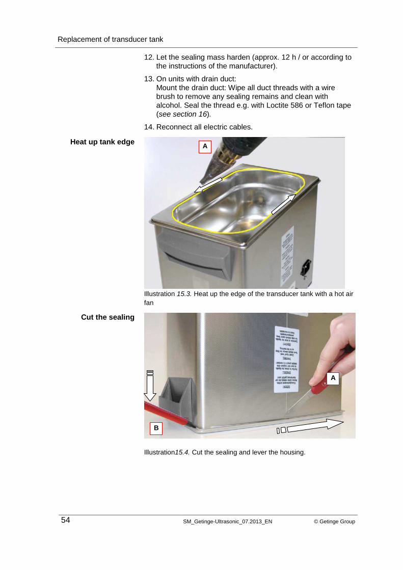
Carefully heat the tank edge around the sealing e.g. with a
hot air fan to make the sealing material flexible (see illustration 15.3.A). Caution! The handles can be damaged
by hot temperatures.
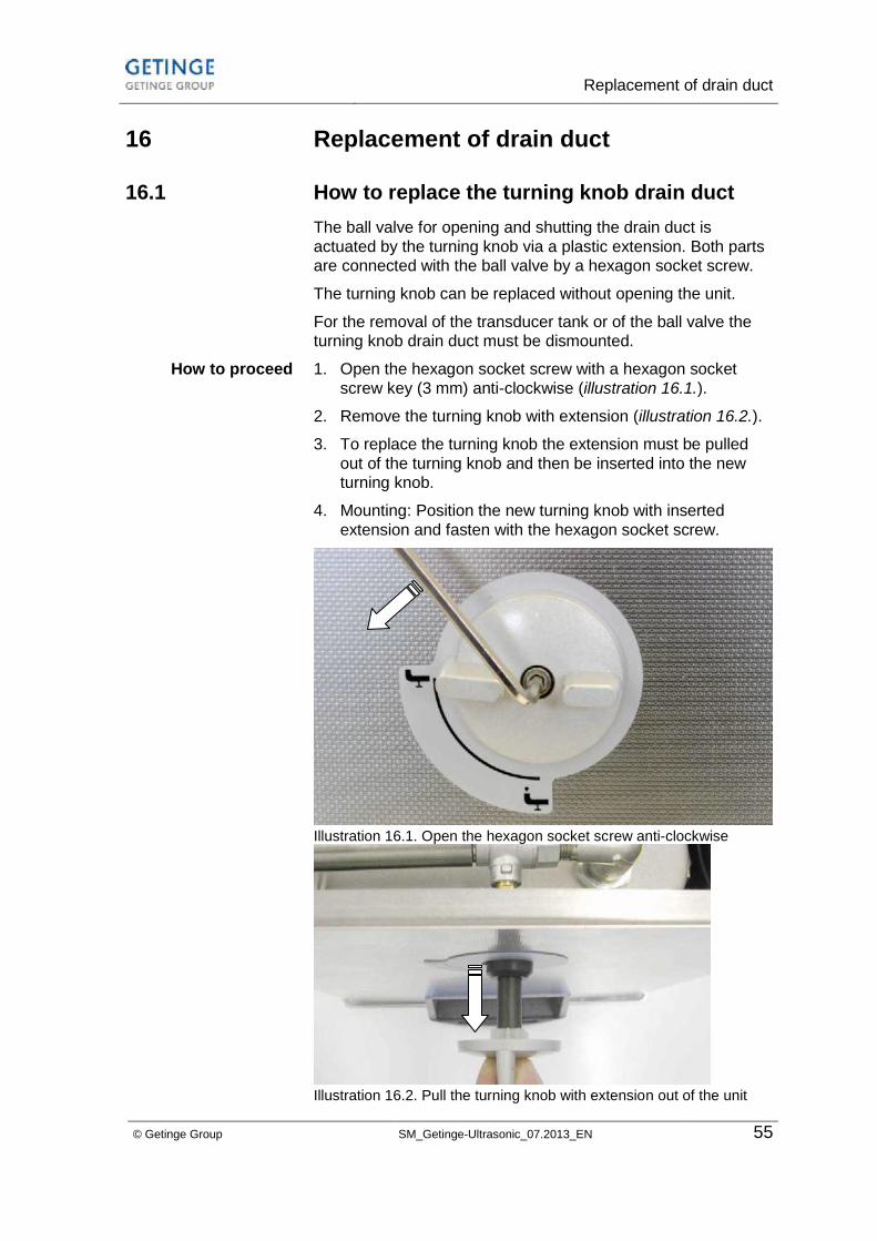
6. Cut the sealing between the tank edge and the housing with
a narrow and flexible knife (see illustration 15.4.A.).
7. Carefully lever the tank out of the housing; cut the sealing
further with the knife if necessary; use the knife to loosen
the tank from the housing (see illustration 15.4.B).
8. Remove the remains of the sealing at the transducer tank
and the housing edge with a knife.
9. Degrease and clean the glueing surfaces of the housing
edge of the (new) tank with alcohol.
10. Fill new sealing material (e.g.Teroson) evenly elong the
edge of the transducer tank.
11. Position the unit housing in the sealing mass. Ensure
correct front and backside positioning.
Tank complete with
transducer system
Tank without
transducer system
How to proceed
Replacement of transducer tank
54 SM_Getinge-Ultrasonic_07.2013_EN © Getinge Group
12. Let the sealing mass harden (approx. 12 h / or according to
the instructions of the manufacturer).
13. On units with drain duct:
Mount the drain duct: Wipe all duct threads with a wire
brush to remove any sealing remains and clean with
alcohol. Seal the thread e.g. with Loctite 586 or Teflon tape
(see section 16).
14. Reconnect all electric cables.
Illustration 15.3. Heat up the edge of the transducer tank with a hot air
fan
Illustration15.4. Cut the sealing and lever the housing.
Heat up tank edge
Cut the sealing
A
A
B
Replacement of drain duct
© Getinge Group SM_Getinge-Ultrasonic_07.2013_EN 55
16 Replacement of drain duct
16.1 How to replace the turning knob drain duct
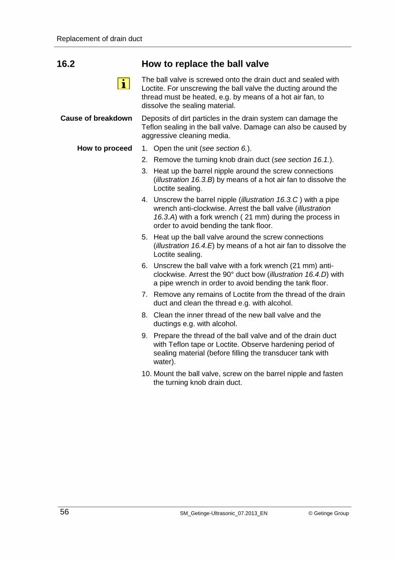
The ball valve for opening and shutting the drain duct is
actuated by the turning knob via a plastic extension. Both parts
are connected with the ball valve by a hexagon socket screw.
The turning knob can be replaced without opening the unit.
For the removal of the transducer tank or of the ball valve the
turning knob drain duct must be dismounted.
1. Open the hexagon socket screw with a hexagon socket
screw key (3 mm) anti-clockwise (illustration 16.1.).
2. Remove the turning knob with extension (illustration 16.2.).
3. To replace the turning knob the extension must be pulled
out of the turning knob and then be inserted into the new
turning knob.
4. Mounting: Position the new turning knob with inserted
extension and fasten with the hexagon socket screw.
Illustration 16.1. Open the hexagon socket screw anti-clockwise
Illustration 16.2. Pull the turning knob with extension out of the unit
How to proceed
Replacement of drain duct
56 SM_Getinge-Ultrasonic_07.2013_EN © Getinge Group
16.2 How to replace the ball valve
The ball valve is screwed onto the drain duct and sealed with
Loctite. For unscrewing the ball valve the ducting around the
thread must be heated, e.g. by means of a hot air fan, to
dissolve the sealing material.
Deposits of dirt particles in the drain system can damage the
Teflon sealing in the ball valve. Damage can also be caused by
aggressive cleaning media.
1. Open the unit (see section 6.).
2. Remove the turning knob drain duct (see section 16.1.).
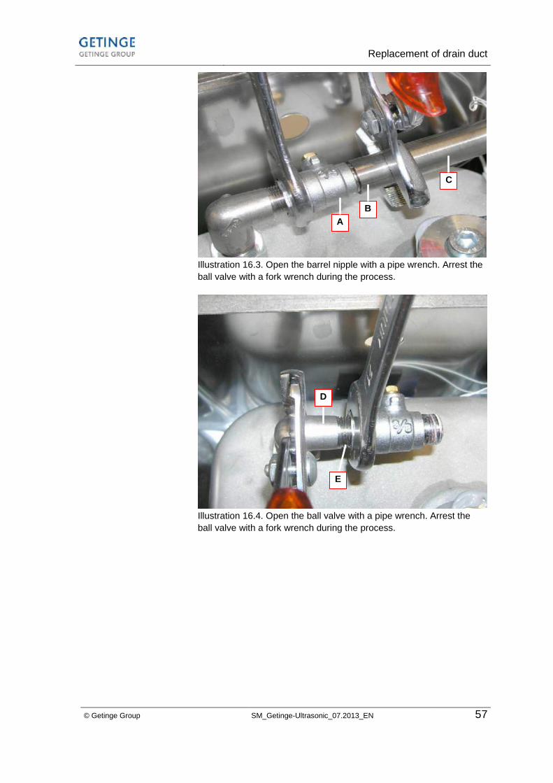
3. Heat up the barrel nipple around the screw connections
(illustration 16.3.B) by means of a hot air fan to dissolve the
Loctite sealing.
4. Unscrew the barrel nipple (illustration 16.3.C ) with a pipe
wrench anti-clockwise. Arrest the ball valve (illustration
16.3.A) with a fork wrench ( 21 mm) during the process in
order to avoid bending the tank floor.
5. Heat up the ball valve around the screw connections
(illustration 16.4.E) by means of a hot air fan to dissolve the
Loctite sealing.
6. Unscrew the ball valve with a fork wrench (21 mm) anti-
clockwise. Arrest the 90° duct bow (illustration 16.4.D) with
a pipe wrench in order to avoid bending the tank floor.
7. Remove any remains of Loctite from the thread of the drain
duct and clean the thread e.g. with alcohol.
8. Clean the inner thread of the new ball valve and the
ductings e.g. with alcohol.
9. Prepare the thread of the ball valve and of the drain duct
with Teflon tape or Loctite. Observe hardening period of
sealing material (before filling the transducer tank with
water).
10. Mount the ball valve, screw on the barrel nipple and fasten
the turning knob drain duct.
Cause of breakdown
How to proceed
Replacement of drain duct
© Getinge Group SM_Getinge-Ultrasonic_07.2013_EN 57
Illustration 16.3. Open the barrel nipple with a pipe wrench. Arrest the
ball valve with a fork wrench during the process.
Illustration 16.4. Open the ball valve with a pipe wrench. Arrest the
ball valve with a fork wrench during the process.
B
A
C
D
E

Replace the handle
58 SM_Getinge-Ultrasonic_07.2013_EN © Getinge Group
17 Replace the handle
The handles are fixed with 2 split pins.
1. Open the unit as described in section 6.
2. Press the 2 split pins with a suitable tool ( for example a
screwdriver and a hammer) downwards out of the handle.
Direction see illustration 1.
3. Remove the old handle outwards the housing.
Illustration 1. Remove the split pins
4. Place the new handle in correct installation position.
5. Fix the handle with the 2 new spilt pins:
push the 2 new split pins, e.g. with a long tweezers, into the
handle.
6. Fix the 2 new split pins and the handle, e.g. with silicone.
How to proceed

Putting into operation / Trial run
© Getinge Group SM_Getinge-Ultrasonic_07.2013_EN 59
18 Putting into operation / Trial run
For checking and trial operation of the unit after repair please
observe the instructions given in this section. We recommend a
trial run over several hours (approx. 3 - 4 h).
Place the unit on a dry and solid workplace. Ensure that the
workplace is sufficiently ventilated!
Risk of electrocution due to entering humidity!
Keep the unit dry.
The unit inside is splash-proof. To prevent electrical accidents
and damage keep the workplace and the unit housing dry.
Allowed ambient temperature during operation:
+5°C to +40°C
Allowed relative humidity of air during operation: 80 %
No condensation allowed
The unit must be connected to a shockproof socket only.
18.1 How to fill cleaning liquid
Fill the cleaning tank of the unit with a sufficient quantity of a
suitable liquid before switch-on.
Dry running of the transducer tank can damage the unit.
Ensure that the cleaning tank is correctly filled during operation
(marking on the tank wall).
Make sure that the selected cleaning chemical is perfectly
suitable for the use in an ultrasonic bath and follow the
instructions on dosage and material compatibility.
In general, flammable products are not allowed for use in an
ultrasonic bath. Observe the safety warnings in section 17.2.
Limitations concerning other cleaning media are also listed in
the warnings in section 17.2.
Fresh cleaning liquid is saturated with air which impairs the
cleaning effect of the ultrasonic activity. Sounding the liquid
over a period of several minutes before the actual cleaning
process is started will eliminate the microscopic air bubbles
from the liquid.
CAUTION
Ambient conditions
Mains connections
Observe filling level
NOTE
Suitable cleaning
media
Prohibited cleaning
media
Degassing of the
liquid

Putting into operation / Trial run
60 SM_Getinge-Ultrasonic_07.2013_EN © Getinge Group
18.2 Cleaning media
When choosing the cleaning chemical ensure that it is suitable
for the use in an ultrasonic bath, as wrong cleaning media can
damage the transducer tank.
Risk of fire and explosion!
Do not use flammable liquids, e.g. solvents, directly in the
ultrasonic cleaning tank.
Ultrasonic activity increases the vapourization of liquids
and creates fine vapours which can catch fire on any
ignition source.
Risk of damage to the transducer tank!
Do not use acid cleaners directly in the stainless-steel tank (pH
value below 7), if at the same time halogenides (fluorides,
chlorides or bromides) will be removed from the cleaning items
or entrained through the cleaning liquid.
The same applies to solvents containing NaCl solutions.
The stainless-steel tank can be damaged by crevice
corrosion within a short period. These substances can be
contained in household cleaners.
If in doubt please contact your distributor or the manufacturer.
18.3 Heating of the cleaning liquid
Choose the required cleaning temperature. The tank must be
filled half (minimum). The optimum filling level is marked on the
tank wall.
For a description of the function please see section
4.5.Operating and Display functions.
18.4 Check ultrasound
After switch-on the liquid must be degassed to remove the
oxygen. With the ultrasound switched on, this takes approx. 5 –
10 minutes depending on the size of the unit.
For a description of the function please see section 4.5.
Operating and Display functions.
CAUTION
NOTE
Setting of
temperature at
turning knob
temperature
Putting into operation / Trial run
© Getinge Group SM_Getinge-Ultrasonic_07.2013_EN 61
After degassing there should be waves visible on the surface of
the cleaning bath.
There must not be any streamers on the floor of the cleaning
tank (floor cavitation).
The power consumption of the ultrasound can be measured
with a standard wattmeter (observe measuring range).
Compare the measured values with the values given in the
table in section 4.4 Technical Details.
For this test the heating remains switched off.
There is a simple method to check the ultrasonic effect in the
cleaning liquid: cavitation check with an aluminum sheet.
Cut a piece of the size and shape of the transducer tank from a
roll of a standard aluminum foil.
Put this sheet vertically into the liquid for 1 minute with the
ultrasound switched on. The ultrasound will tear pieces out of
the sheet. The size of the torn holes indicates the zones of
different cleaning intensity in the cleaning tank. It is normal that
the number of holes is bigger around the transducer elements.
Visual check
Power consumption
Aluminum sheet test

Putting out of operation and disposal
62 SM_Getinge-Ultrasonic_07.2013_EN © Getinge Group
19 Putting out of operation and disposal
The components can be given to electronic and metal recycling
stations or returned to the manufacturer for the same purpose.
20 Contact address
Getinge Infecction Control AB
Box 69
30505 Getinge
Phone +46 (0) 10 335 00 00
e-mail: [email protected]
Please visit our homepage. You will find helpful information and
descriptions on our large product range:
www.getinge.com
21 Conclusion
If you have problems in finding or repairing a fault we
recommend to return the unit to the supplier or manufacturer for
inspection and repair.
Please include a short note describing the original cause of the
malfunction and which repair works you have carried out.
Subje
ct to
technic
al and
vis
ual m
odific
ations_0
7.2
01
3
Technis
che D
ate
n
Technis
che D
ate
n
Technis
che D
ate
n
Technis
che D
ate
n
Technis
che D
ate
n
Technis
che D
ate
n
Technis
che D
ate
n
Technis
che D
ate
n
Te
chn
isch
e u
nd o
ptisch
e Ä
nde
run
gen
vo
rbeh
alte
n E
lma
_ch_
06
/02


