Problem• How to connect two (or more) nodes directly to each
other?• Link layer addresses direct connection issues
– Encoding– Framing– Error detection– Reliable delivery– Access mediation when several hosts share the
transmission medium
4
Chapter outline• Host hardware and physical link technologies• Encoding• Framing Topics of CMPE 444• Error detection/correction• Reliable transmission• Multiple access techniques
– Ethernet– Wireless
5
Network nodes• Node types: End hosts (general-purpose
computers), routers (special-purpose hardware)• End host structure
– Incoming packets stored in memory(finite and possibly scarce)
– Network adapter connects host to physical medium delivering packets from memory to physical link and receiving packets from the link and storing them in memory
– Small buffer between bus interface and link interface (I/O bus and link operate at different speeds)
– Link layer functions implemented in adapter hardware
– Device driver manages the adapter• End hosts run at memory speeds, not processor
speeds!– Memory delay halves every 10 years,
processor speeds double every 1.5 years
6
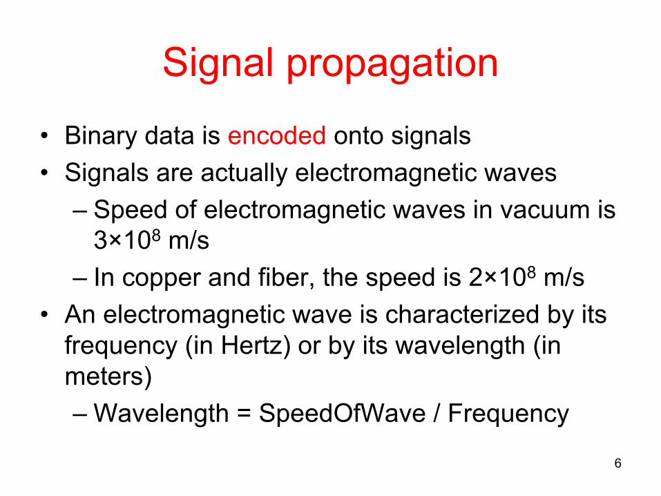
Signal propagation• Binary data is encoded onto signals• Signals are actually electromagnetic waves
– Speed of electromagnetic waves in vacuum is 3×10⁸ m/s
– In copper and fiber, the speed is 2×10⁸ m/s• An electromagnetic wave is characterized by its
frequency (in Hertz) or by its wavelength (in meters)– Wavelength = SpeedOfWave / Frequency
• Modulation involves modifying the signals in terms of their frequency, amplitude, and phase (responsibility of physical layer)• Signals must often be modulated to appropriate frequencies before they can be transmitted
8
Physical link technologies• Physical media are used to propagate signals
– Guided propagation versus unguided propagation• Variety of physical media
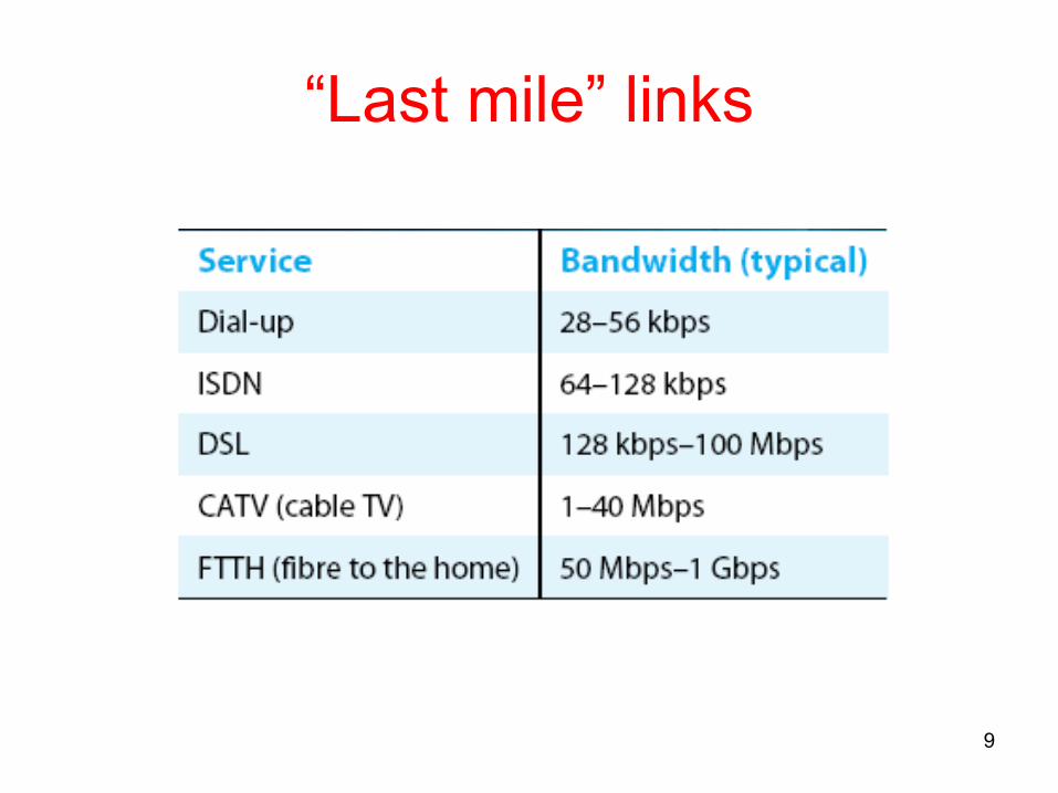
• Selection of media may be based on type of network– connections within a building/campus area– connections across a city/country– “last mile” connections
9
“Last mile” links
10
Long-distance links• Modern long-distance links are almost exclusively fiber today
(CMPE 447 Fiber Optics)• T-carriers (Digital Signal (DS) format)
STS: Synchronous Transport Signal (Electrical)OC: Optical Carrier (Optical)
11
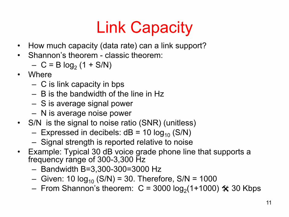
Link Capacity• How much capacity (data rate) can a link support?• Shannon’s theorem - classic theorem:
– C = B log2 (1 + S/N)• Where
– C is link capacity in bps– B is the bandwidth of the line in Hz– S is average signal power– N is average noise power
• S/N is the signal to noise ratio (SNR) (unitless)– Expressed in decibels: dB = 10 log10 (S/N)– Signal strength is reported relative to noise
• Example: Typical 30 dB voice grade phone line that supports a frequency range of 300-3,300 Hz– Bandwidth B=3,300-300=3000 Hz– Given: 10 log10 (S/N) = 30. Therefore, S/N = 1000– From Shannon’s theorem: C = 3000 log2(1+1000) @ 30 Kbps
12
Encoding, framing, error detection/correction
• Encoding: representing the binary data that the source node wants to send into signals that the links are able to carry(e.g. 1º high voltage=+5V; 0 º low voltage=-5V)
Øerrors caused by signal attenuation, noiseØ receiver detects presence of errors (e.g. using CRC (Cyclic
Redundancy Check))Øsignals sender for retransmission (e.g. ARQ) or drops frame
– Correction: Ø receiver identifies and corrects bit error(s) without resorting to
retransmission (Forward Error Correction: FEC)
Bit and packet error rate• A good transmission channel must have a small error
probability (BER: bit error rate)– Optical: BER ~ 10-9
– Transmission lines: BER ~ 10-7
• Consider synchronous transmission with packets of N bits– Assuming that bit errors are independent, we can
calculate the packet error rate (PER)– The probability that the N bits are not all received
correctly is PER=1-(1-BER)N
– If N×BER<<1, then PER≈N×BER– E.g., if N=105 and BER=10-7, then PER≈10-2
13
A simple error correction coding example
• Send every packet three times• Three values are values are received for each bit• Probability that a given bit is incorrectly received 2 or 3 times is
– 𝛜 = 32 ×BER2(1-BER)+ 33 ×BER3
– 𝛜 = 3×BER2(1-BER)+BER3
• Probability that at least one of the N bits of the packet is received incorrectly two or three times is (higher order terms are neglected)– PERc=1-(1- 𝛜)N ≈N×𝛜 ≈ 3N×BER2
• E.g., if N=105 and BER=10-7, then PERc≈3×10⁻⁹ !• Price paid: Useful transmission rate reduced by a factor of 3• There exists much more efficient error correction methods
14
15
Reliable transmission• Frames may be corrupted or simply dropped (due to
congestion)• A link layer protocol that reliably delivers frames must
recover lost frames by retransmitting them• Two fundamental mechanisms for recovery:
– Acknowledgements (ACKs): short control frame from the receiver acknowledging a successfully received frame. When data frames are sent back, an ACK can be piggybacked onto the data frames– Timeouts: Sender waits for a “reasonable” time for an ACK of a sent frame. If an ACK is not received, a timeout occurs and that frame is retransmitted
• Two error control ARQ (Automatic Repeat Request) algorithms– Stop-and-wait and sliding window
16
Stop-and-wait• Allow only one
outstanding frame at any given time
• If ACK not received within timeout, send again
• To solve (c) and (d), use 1-bit sequence numbers: Frame0, Ack0; Frame1, Ack1
Sender Receiver
Frame
ACK
Sender Receiver
Frame
ACK
Frame
ACK
Sender Receiver
Frame
ACK
Frame
ACK
Sender Receiver
Frame
Frame
ACK
(a) (c)
(b) (d)
17
How efficient is Stop-and-Wait?
• Consider a 1.5 Mbps link with 45 ms RTT.• Bandwidth - Delay product = 67.5 Kb » 8KB.• You can fill 8 Kbytes of data prior to receiving an
ACK.• However, if your frame size is 1 KB, you are
using only 1/8 of the capacity. Very inefficient!(i.e. utilization »12.5%)– Possible remedy : send more than one frame
before receiving ACKs (Sliding window)
How efficient is Stop-and-Wait in channels with errors?
• Let 1 – Pf = probability frame arrives w/o errors• Avg. # of transmissions to first correct arrival is then 1/ (1–Pf )• “If 1-in-10 get through without error, then avg. 10 tries to
success”• Let t0 be the total time required to transmit one frame• Avg. Total Time per frame is then t0/(1 – Pf) • Define the efficiency as follows
– 𝜂=Throughput/Bandwidth• If the efficiency in channels without errors is 𝜂, then the
efficiency with errors is 𝜂×(1 – Pf)
19
Sliding window• Algorithm that allows the sender to transmit multiple packets (up to
an upper bound called the window size) before receiving an ACK- the method used in the Internet retransmission schemes
• As ACKs are received window slides, i.e., more frames aresent
• The algorithm needs to know which frames have been received and which have not, so frames are labeled using sequence numbers.
Sender Receiver
Roles of sliding window• Ensures reliability
– Retransmissions• Preserves the order of frames
– Sequence numbers• Exercises flow control
– Receiver can throttle the sender
20
21
Multiple access links and protocolsTwo types of “links”:• point-to-point
– PPP for dial-up access– point-to-point link between Ethernet switch and host
• broadcast (shared wire or medium)– traditional Ethernet– 802.11 wireless LAN
• Medium access or multiple access problem: In a broadcast link where the link is shared by multiple nodes, it is necessary to mediate access to the medium– MAC = Medium Access Control – Responsibility of link layer
22
Ethernet overview• First widely used and “dominant” LAN technology• Roots in ALOHA, standardized by Xerox, DEC, and Intel
in 1978, (later IEEE 802.3 standard)• Simpler, cheaper than token LANs and ATM• Bandwidth: 10 Mbps, 100 Mbps, 1Gbps• Uses CSMA/CD (see next slide)
Metcalfe’s Ethernetsketch
23
CSMA/CD• CSMA/CD: Carrier Sense Multiple Access with Collision
Detection• A random access MAC mechanism
– Contrast with channel partitioning and polling• A set of nodes send and receive frames over a shared
link• Carrier sense means that all nodes can distinguish
between an idle and a busy link• Collision detection means that a node listens as it
transmits and can therefore detect when a frame it is transmitting has collided with a frame transmitted by another node.
24
Classical Ethernet transceiver and adaptor
• Ethernet segment (different coaxial cables, max 500 m):– transceiver: detects if line is idle, sends the electrical signals– adapter: implements the Ethernet MAC protocol (in hardware)
25
Ethernet repeaters• Maximum 4 repeaters can be used. At most 5 segments can be connected
– Maximum reach: 2500 m• Hubs can be used to create a star (hierarchical) topology
– used in 10BaseT networks with twisted pair cabling– 10 = 10 Mbps, Base = Baseband system, T=twisted pair (< 100 m)
• Repeaters and hubs are layer 1 devices connecting Ethernet segments– data transmitted by any host on that Ethernet is received by all hosts (broadcast)– all compete for the same resource– all hosts are in the same collision domain
26
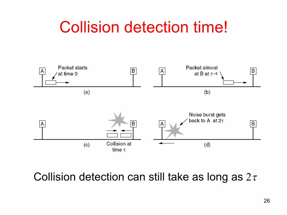
Collision detection time!
Collision detection can still take as long as 2t
27
Ethernet• Including the propagation delay for 2500 m and the
store-and-forward delay in 4 repeaters, the maximum time for a bit to travel between any two stations is tmax=25.6 µs (or, 51.2 µs Round-trip time)
• Frame size must be at least 512 bits for a 10-Mbps Ethernet. Why?
• We want:– Sender to be able to detect collisions– Sender sensing no collision implies successful
reception by all nodes on the wire (LAN)– At what frame size is the propagation delay equal to
the transmit delay? (Recall Chapter 1)• Thus:
– Transmissions of packets must be long enough– Distance between nodes short enough
28
Ethernet frame format• Frame Format (field lengths in bits)
– max body length 1500 bytes– min body length 46 bytes (long enough to detect a collision)
Preamble: 64 bits of alternating 0s and 1s which is used to synchronize receiver with sender
Addresses: unique 48-bit unicast address assigned to each adapter For broadcast: all bits are set to 1; for multicast: first bit is 1 Adapter forwards to the host all unicast traffic directed to it, all broadcast traffic and the multicast traffic it has subscribed to
Type: indicates the higher layer protocol, mostly IP but others may be supported such as Novell IPX and AppleTalk)
CRC: checked at receiver, if error is detected, the frame is simply dropped
Ethernet receiver• Simple• An Ethernet adaptor receives all frames and
accepts frames addressed to– Its own address– To the broadcast address– A multicast address for which it is
programmed• If the adaptor is in promiscuous mode, it accepts
all the frames (not just those addressed to it)
29
30
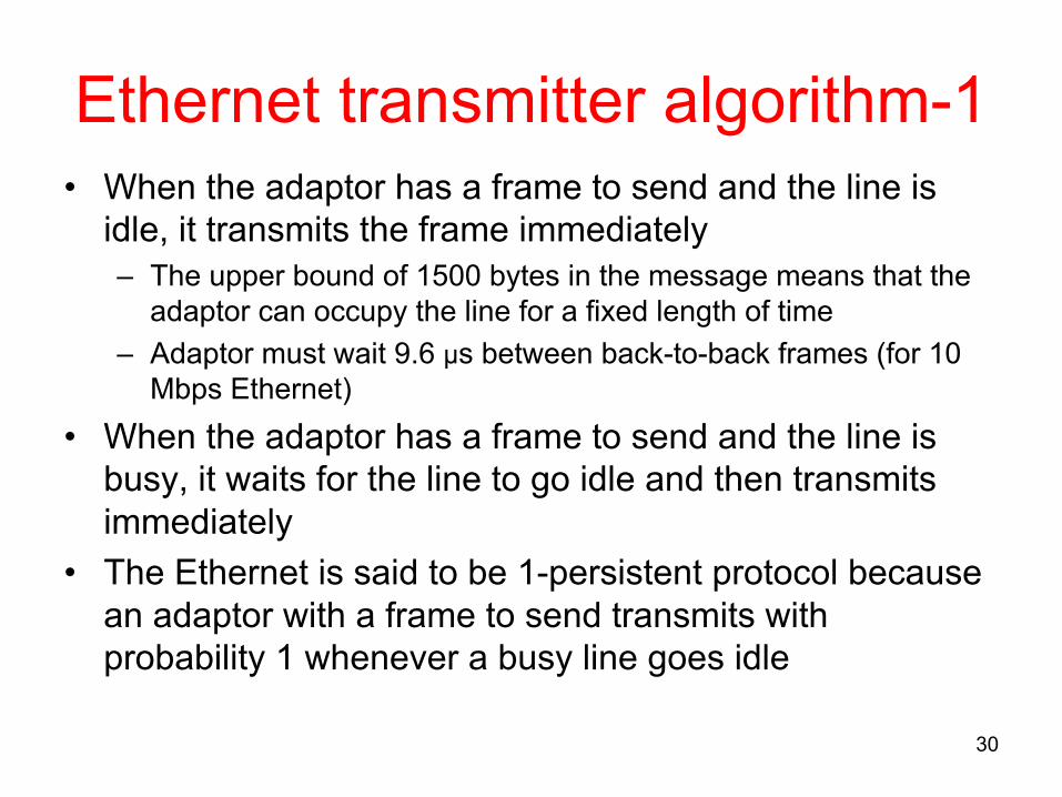
Ethernet transmitter algorithm-1• When the adaptor has a frame to send and the line is
idle, it transmits the frame immediately– The upper bound of 1500 bytes in the message means that the
adaptor can occupy the line for a fixed length of time– Adaptor must wait 9.6 µs between back-to-back frames (for 10
Mbps Ethernet)• When the adaptor has a frame to send and the line is
busy, it waits for the line to go idle and then transmits immediately
• The Ethernet is said to be 1-persistent protocol because an adaptor with a frame to send transmits with probability 1 whenever a busy line goes idle
31
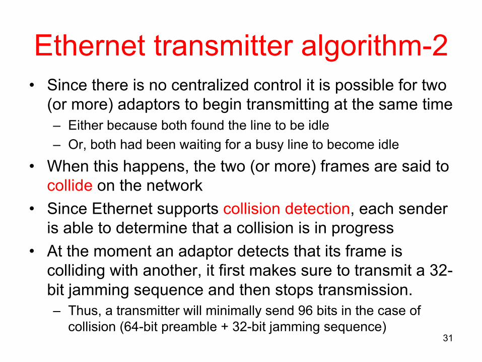
Ethernet transmitter algorithm-2• Since there is no centralized control it is possible for two
(or more) adaptors to begin transmitting at the same time– Either because both found the line to be idle– Or, both had been waiting for a busy line to become idle
• When this happens, the two (or more) frames are said to collide on the network
• Since Ethernet supports collision detection, each sender is able to determine that a collision is in progress
• At the moment an adaptor detects that its frame is colliding with another, it first makes sure to transmit a 32-bit jamming sequence and then stops transmission.– Thus, a transmitter will minimally send 96 bits in the case of
Exponential backoff• Once an adaptor has detected a collision and stopped
transmission, it waits a certain amount of time and tries again
• Each time it tries to transmit but fails, the adaptor doubles the amount of time it waits before trying again
• In fact, more precisely, an Ethernet adapter, after– 1st collision waits 0 or 51.2 µs– 2nd collision waits 0 or 51.2 or 102.4, or 153.6 µs– nth collision waits k´51.2 µs, for randomly selected
k=0...2n-1– The adapter gives up after several tries (usually 16)
32
33
Ethernet in practice• Performance
– Ethernet works best under light load– 30% load is considered a heavy load and too much of Ethernet’s capacity is wasted on collisions– no flow control in Ethernet (flow control implemented by upper layer, eg. TCP/IP protocols)
• Number of hosts– theoretical maximum 1024 hosts– in reality most have < 200 hosts
• Length– theoretical maximum 2500 m with round-trip delay 51.2 µs– in practice, delay is closer to 5 µs
• Ethernet advantages:– easy to manage and administer (add/remove hosts)– cheap
– Radio, microwave, infrared• Wireless links all share the same “wire”
– The challenge is to share it efficiently without unduly interfering with each other
– Most of this sharing is accomplished by dividing the “wire” along the dimensions of frequency and space
• Frequency ranges are allocated to certain uses by the government– AM/FM radio, TV, satellite, cellular, etc.– Several frequency bands are license exempt
34
Leading wireless technologies
35
36
Wireless LANs• (Original) Wireless LAN standard: IEEE 802.11
– limited geographical coverage– defines MAC protocol suitable for wireless environment– additional features: real time support, power mgmt, security
• Physical properties– bandwidth: 1 or 2 Mbps– physical media based on spread spectrum radio operating in 2.4 GHz frequency range or diffused infrared (sender and receiver do not need to have line of sight contact) with distance limitation approx. 10 m
• Newer standards– IEEE 802.11a, IEEE 802.11b, IEEE 802.11g, and IEEE 802.11n– Higher data rates: 10 Mbps up to 54 Mbps– 802.11n uses multiple antennas (MIMO: multiple input multiple output) to achieve very high data rates
37
Spread spectrum techniques-1• Spread spectrum technique is used to share the spectrum• General principles
– signal spread over wider frequency band than required– minimizes impact of interference from other devices– originally military technology, deigned to prevent jamming– transmission “coded” such that the signal appears as noise to an observer not knowing the “key”
• Frequency hopping– signal transmitted over random sequence of frequencies– sender and receiver share
• pseudorandom number generator• seed
– receiver can hop frequencies in sync– 802.11 uses 79 x 1MHz-wide frequency bands
38
Spread spectrum techniques-2• Direct sequence
– for each bit, send XOR of that bit and n random bits– random sequence known to both sender and receiver– called n-bit chipping code– 802.11 defines an 11-bit chipping code
39
Using a base station• Wireless host communicates with a base
station• Basic Service Set (BSS) (cell) contains:
– wireless hosts– base station or access point (AP)
• BSSs combined to form distribution system (DS)
40
Ad hoc or mesh network• No AP (i.e., no base station)• Wireless hosts communicate with each other
– to get packet from wireless host A to B may need to route through wireless hosts X,Y,Z
• Applications:– “laptop” meeting in conference room, car– interconnection of “personal” devices– battlefield
• IETF MANET Mobile Ad hoc Networks working group
41
MAC for wireless-1• In wireless environment not all nodes are always within reach of
each other• Additional complication: A wireless node cannot transmit and
receive at the same time. This makes collision detection hard– Power generated by transmitter is much higher than any
received signal and so swamps the receiving circuitry• Problem 1: hidden nodes
– Assume node A and C want to transmit to B– A and C are unaware of each other– transmissions collide at B, but A and C do not know about that
42
MAC for wireless-2• Problem 2: exposed nodes
– suppose B is sending to A– C hears this– however, C can still transmit to D
• Wireless MAC addresses the problems by collision avoidance strategy
43
MACAW• MACAW (MACA for Wireless LANs)
– MACA = Multiple Access with Collision Avoidance– idea: nodes ask for permission to send
• that see CTS: keep quiet (they are too close to sender)• that see RTS but not CTS: ok to transmit
– receiver sends ACK when it has received the frame• neighbors silent until see ACK
– Collisions (= multiple RTS frames sent at the same time)• no collision detection• known when senders do not receive CTS• exponential backoff
IEEE 802.11 distribution system
44
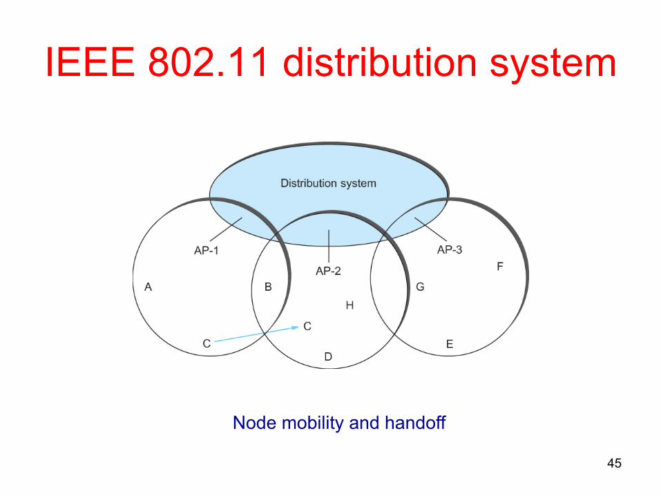
Access points connected to a distribution network
IEEE 802.11 distribution system
45
Node mobility and handoff
IEEE 802.11 frame format• Source and Destinations addresses: each 48 bits• Data: up to 2312 bytes• CRC: 32 bit• Control field: 16 bits
– Contains three subfields (of interest)• 6 bit Type field: indicates whether the frame is an RTS or
CTS frame or being used by the scanning algorithm• A pair of 1 bit fields : called ToDS and FromDS
46
IEEE 802.11 frame format• Frame contains four addresses• How these addresses are interpreted depends on the settings of the ToDS and FromDS bits in the frame’s Control field
• This is to account for the possibility that the frame had to be forwarded across the distribution system which would mean that,– the original sender is not necessarily the same as the most recent
transmitting node• Same is true for the destination address• Simplest case
– When one node is sending directly to another, both the DS bits are 0, Addr1 identifies the target node, and Addr2 identifies the source node
• Most complex case– Both DS bits are set to 1– A transmits to E: Addr1: E, Addr2: AP-3, Addr3: AP-1, Addr4: A (see
slide 45) 47
48
Bluetooth (802.15) overview• Low-power, small radius,
wireless networking technology– 10-100 meters
• omnidirectional– not line-of-sight
infrared• 2.4-2.5 GHz unlicensed
radio band• up to 721 kbps
• Interference from wireless LANs, digital cordless phones, microwave ovens:– frequency hopping
helps• MAC protocol supports:
– error correction– ARQ
• Each node has a 12-bit address
49
Bluetooth piconet
50
Cell phone technologies-1• Obvious approach to mobile communications• Use of licensed spectrum:
– Europe: 900/1800 MHz– North America: 850/1900 MHz– For traveling users: Tri-band phones can operate at
multiple different frequency bands• To utilize the scarce radio spectrum (channels) in
wireless networks, cellular architecture is used for frequency reuse.
• Base station serves a geographic area called a cell
51
Cell phone technologies-2
• As cellular user moves from one cell to another a handoff takes place– The ongoing call is transferred to the new base