39
Getting Started with Pivotal Container Server (PKS) Rafay Systems 530 Lakeside Drive, Suite 210 Sunnyvale, CA 94086 rafay.co [email protected] © Rafay Systems 2019. All Right Reserved.

Getting Started with Pivotal Container Server (PKS)
Rafay Systems
530 Lakeside Drive, Suite 210
Sunnyvale, CA 94086
rafay.co
© Rafay Systems 2019. All Right Reserved.

© 2019 Rafay Systems. All Rights Reserved. 2
Getting started with Pivotal Container Server Pivotal Container Service (PKS) is a managed Kubernetes service for developers to operate and manage enterprise-grade Kubernetes clusters using BOSH and Pivotal Ops Manager. PKS uses the On-Demand Broker to deploy Cloud Foundry Container Runtime, a BOSH release that offers a uniform way to instantiate, deploy, and manage highly available Kubernetes clusters on a cloud platform using BOSH. After operators install the PKS tile on the Ops Manager Installation Dashboard, developers can provision Kubernetes clusters using the PKS Command Line Interface (PKS CLI), and run container-based workloads on the clusters with the Kubernetes CLI, kubectl.
Architecture This section describes how Pivotal Container Service (PKS) manages the deployment on Kubernetes clusters. Developers interact with PKS and PKS-deployed Kubernetes in two ways:
• BOSH is used to deploy the Kubernetes clusters and to manage its lifecycle. These tasks are performed using the PKS Command Line Interface (PKS CLI) and the PKS control plane.
• The Kubernetes CLI, kubectl, is used to deploy and manage container-based workloads on Kubernetes clusters.
The following architectural diagram shows how components interact:

© 2019 Rafay Systems. All Rights Reserved. 3
PKS Control Plane
The PKS control plane manages the lifecycle of Kubernetes clusters deployed using PKS CLI. The control plan allows users to create, scale and manage cluster using BOSH. The PKS API LoadBalancer is used for interaction with PKS control plane.
UAA
PKS CLI communicates with UAA to authenticate log in and log out of PKS API through PKS API.
PKS API
With PKS CLI, users instruct the PKS API server to deploy, scale up, and delete Kubernetes clusters as well as show cluster details and plans.
PKS Broker
When the PKS API receives a request to modify a Kubernetes cluster, it instructs the PKS Broker to make the requested change. The PKS Broker generates a BOSH manifest and instructs the BOSH Director to deploy or delete the Kubernetes cluster.

© 2019 Rafay Systems. All Rights Reserved. 4
Overview This guide is designed to help you to get started with Pivotal container service (PKS). You can install PKS on Amazon Web Services (AWS), Google Cloud Platform (GCP), or vSphere. We will be using Amazon Web Services for setting up the control plane. This guide will walk through the steps to :
• Deploying Ops Manager • Configuring BOSH Director • Installing PKS on AWS • Installing the PKS CLI and Kubectl • Configuring the PKS API • Creating a Load Balancer for PKS clusters • Creating a Kubernetes Cluster • Deploying Nginx application
Deploying Ops Manager This guide describes the preparation steps required to deploy Ops Manager on Amazon Web Services (AWS) using Terraform templates.
Prerequisites Before you deploy Ops Manager on AWS, ensure you have the following:
• The Terraform CLI (LINK -> https://learn.hashicorp.com/terraform/getting-started/install.html).
• In your AWS account, ensure you have an IAM user with the following permissions:
• AmazonEC2FullAccess • AmazonRDSFullAccess • AmazonRoute53FullAccess • AmazonS3FullAccess • AmazonVPCFullAccess • IAMFullAccess • AWSKeyManagementServicePowerUser

© 2019 Rafay Systems. All Rights Reserved. 5
Download Templates and Edit Variables File Before you can run Terraform commands to provision infrastructure resources, you must download the AWS Terraform templates and create a Terraform template variables file as described below:
• On Pivotal Network(LINK: https://network.pivotal.io), navigate to the Pivotal Application Service (formerly Elastic Runtime) release.
• Download the AWS Terraform templates ZIP file. • Extract the contents of the ZIP file. • Move the extracted folder to the workspace directory on your local machine. • On the command line, navigate to the directory. For example:
• Navigate to the terraforming-pas or terraforming-pks directory that contains the Terraform files for your runtime.
• In the runtime directory, create a text file named terraform.tfvars.
• Open the terraform.tfvars file and add the following:
• Edit the values in the file according to your AWS environment.
cd ~/workspace/pivotal-cf-terraforming-aws
env_name = "YOUR-ENVIRONMENT-NAME" access_key = "YOUR-ACCESS-KEY" secret_key = "YOUR-SECRET-KEY" region = "YOUR-AWS-REGION" availability_zones = ["YOUR-AZ-1", "YOUR-AZ-2", "YOUR-AZ-3"] ops_manager_ami = "YOUR-OPS-MAN-IMAGE-AMI" dns_suffix = "YOUR-DNS-SUFFIX" ssl_cert = <<SSL_CERT -----BEGIN CERTIFICATE----- YOUR-CERTIFICATE -----END CERTIFICATE----- SSL_CERT ssl_private_key = <<SSL_KEY -----BEGIN EXAMPLE RSA PRIVATE KEY----- YOUR-PRIVATE-KEY -----END EXAMPLE RSA PRIVATE KEY----- SSL_KEY

© 2019 Rafay Systems. All Rights Reserved. 6
Create AWS Resources with Terraform Follow these steps to use the Terraform CLI to create resources on AWS:
• From the directory that contains the Terraform files, run terraform init to initialize the directory based on the information you specified in the terraform.tfvars file.
• Run terraform plan -out=plan to create the execution plan for Terraform.
• Run terraform apply plan to execute the plan from the previous step. It may take several minutes for Terraform to create all the resources in AWS.

© 2019 Rafay Systems. All Rights Reserved. 7
Create DNS Record • In a browser, navigate to the DNS provider for the DNS suffix you entered in
your terraform.tfvars file.
• Create a new NS record for your system domain. Your system domain is YOUR-
ENVIRONMENT-NAME.YOUR-DNS-SUFFIX.
• In this record, enter the name servers included in env_dns_zone_name_servers from your Terraform output.
• Alternatively, you can use the Public DNS of the instance launched with terraform in your hosts file.
© 2019 Rafay Systems. All Rights Reserved. 8
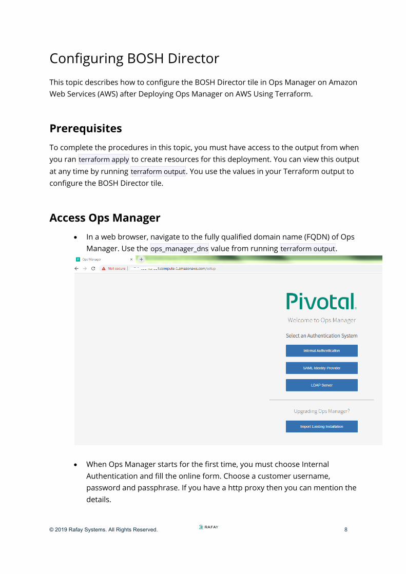
Configuring BOSH Director This topic describes how to configure the BOSH Director tile in Ops Manager on Amazon Web Services (AWS) after Deploying Ops Manager on AWS Using Terraform.
Prerequisites To complete the procedures in this topic, you must have access to the output from when you ran terraform apply to create resources for this deployment. You can view this output at any time by running terraform output. You use the values in your Terraform output to configure the BOSH Director tile.
Access Ops Manager • In a web browser, navigate to the fully qualified domain name (FQDN) of Ops
Manager. Use the ops_manager_dns value from running terraform output.
• When Ops Manager starts for the first time, you must choose Internal
Authentication and fill the online form. Choose a customer username, password and passphrase. If you have a http proxy then you can mention the details.

© 2019 Rafay Systems. All Rights Reserved. 9
• Login to the Ops manager with the username password which was
configured.

© 2019 Rafay Systems. All Rights Reserved. 10
Configure AWS BOSH Director
• Click the BOSH Director tile.

© 2019 Rafay Systems. All Rights Reserved. 11
• Select AWS Config to open the AWS Management Console Config page.
• Select Use AWS Keys or Use AWS Instance Profile. • If you choose to use AWS keys, complete the following fields:
o Access Key ID: Enter the value of ops_manager_iam_user_access_key from the Terraform output.
o AWS Secret Key: Enter the value of ops_manager_iam_user_secret_key from the Terraform output.
• If you choose to use an AWS instance profile, enter the name of your AWS Identity and Access Management (IAM) profile or enter the value of ops_manager_iam_instance_profile_name from the Terraform output.
• Complete the remainder of the AWS Management Console Config page with the following information. • Security Group ID: Enter the value of vms_security_group_id from the
Terraform output.

© 2019 Rafay Systems. All Rights Reserved. 12
• Key Pair Name: Enter the value of ops_manager_ssh_public_key_name from the Terraform output.
• SSH Private Key: Run terraform output to view the value of ops_manager_ssh_private_key and enter it into this field. ops_manager_ssh_private_key is a sensitive value and does not display when you run terraform apply.
• Region: Select the region where you deployed Ops Manager. • Encrypt EBS Volumes: Select this checkbox to enable full encryption on
persistent disks of all BOSH-deployed virtual machines (VMs), except for the Ops Manager VM and BOSH Director VM. See the Configuring Amazon EBS Encryption topic for details about using Elastic Block Store (EBS) encryption.
§ Custom Encryption Key (Optional) Once you enable EBS encryption, you may want to specify a custom Key Management Service (KMS) encryption key. If you don’t enter a value, your custom encryption key will default to the account key. For more information, see Configuring Amazon EBS Encryption.
• Click Save.
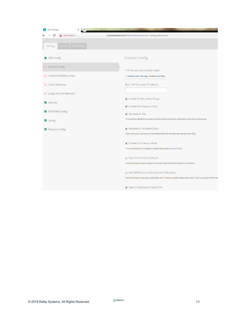
Director Config Page • Select Director Config to open the Director Config page. • Fill the details given in the below illustration. Enter at least two of the
following NTP servers in the NTP Servers (comma delimited) field, separated by a comma:
0.amazon.pool.ntp.org,1.amazon.pool.ntp.org,2.amazon.pool.ntp.org,3.amazon.pool.ntp.org
© 2019 Rafay Systems. All Rights Reserved. 13

© 2019 Rafay Systems. All Rights Reserved. 14
Create Availability Zones Page • Select Create Availability Zones. • Use the following steps to create three Availability Zones for your apps to use:
• Click Add three times. • For Amazon Availability Zone, enter the values corresponding to the
key infrastructure_subnet_availability_zones from the Terraform output. • Click Save.

© 2019 Rafay Systems. All Rights Reserved. 15
Create Networks Page • Select Create Networks. • Enter the details as given in the below screenshot. The value of subnets has been
taken from the “terraform output”

© 2019 Rafay Systems. All Rights Reserved. 16
• Add another Network. Give the name as ‘pks’ and fill the form as given as per the below screenshot. Take the values from the output of “terraform output”

© 2019 Rafay Systems. All Rights Reserved. 17
• Add another Network. Give the name as ‘services’ and fill the form as given as per the below screenshot. Take the values from the output of “terraform output”.

© 2019 Rafay Systems. All Rights Reserved. 18
• Save all the network configuration
Assign AZs and Networks Page • Select Assign AZs and Networks. • Use the dropdown to select a Singleton Availability Zone. The BOSH Director
installs in this availability zone (AZ). • Use the dropdown to select the infrastructure network for your BOSH Director. • Click Save.

© 2019 Rafay Systems. All Rights Reserved. 19
Security Page • Select Security. • In Trusted Certificates, enter your custom certificate authority (CA) certificates
to insert into your organization’s certificate trust chain. • Choose Generate passwords or Use default BOSH password. Pivotal
recommends that you use the Generate passwords option for greater security.
• Click Save. To view your saved Director password, click the Credentials tab.
© 2019 Rafay Systems. All Rights Reserved. 20
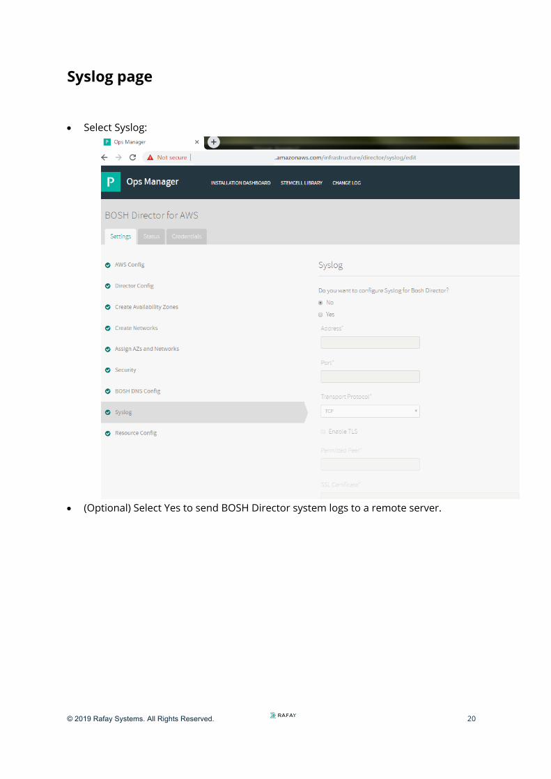
Syslog page
• Select Syslog:
• (Optional) Select Yes to send BOSH Director system logs to a remote server.

© 2019 Rafay Systems. All Rights Reserved. 21
Resource Config Page • Select Resource Config.
Complete the BOSH Director Installation • Click the Installation Dashboard link to return to the Installation Dashboard. • Click Apply Changes. If the following ICMP error message appears, click Ignore errors
and start the install.
• BOSH Director installs. This may take a few moments. When the installation process successfully completes, the Changes Applied window appears.

© 2019 Rafay Systems. All Rights Reserved. 22
Installing PKS on AWS
This topic describes how to install and configure Pivotal Container Service (PKS) on Amazon Web Services (AWS).
Prerequisites Before performing the procedures in this topic, you must have deployed and configured Ops Manager. This topic assumes that you used Terraform to prepare the AWS environment for this Pivotal Container Service (PKS) deployment. You retrieve specific values required by this deployment by running terraform output.
If you use an instance of Ops Manager that you configured previously to install other runtimes, confirm the following settings before you install PKS:
• Navigate to Ops Manager. • Open the Director Config pane. • Select the Enable Post Deploy Scripts checkbox. • Clear the Disable BOSH DNS server for troubleshooting purposes checkbox. • Click the Installation Dashboard link to return to the Installation Dashboard. • Click Review Pending Changes. Select all products you intend to deploy and review
the changes. • Click Apply Changes.
© 2019 Rafay Systems. All Rights Reserved. 23
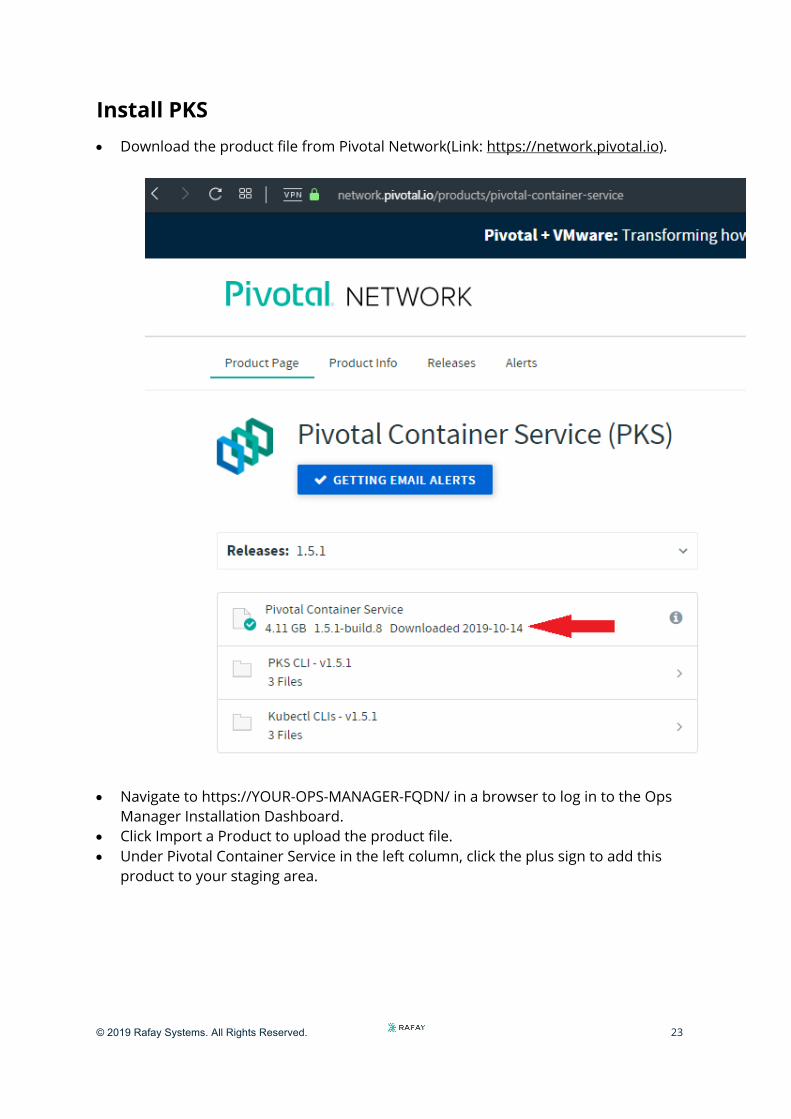
Install PKS • Download the product file from Pivotal Network(Link: https://network.pivotal.io).
• Navigate to https://YOUR-OPS-MANAGER-FQDN/ in a browser to log in to the Ops Manager Installation Dashboard.
• Click Import a Product to upload the product file. • Under Pivotal Container Service in the left column, click the plus sign to add this
product to your staging area.

© 2019 Rafay Systems. All Rights Reserved. 24
Configure PKS • Click the orange Pivotal Container Service tile to start the configuration process.

© 2019 Rafay Systems. All Rights Reserved. 25
Assign AZs and Networks • Click Assign AZs and Networks. • Select the availability zone (AZ) where you want to deploy the PKS API VM as a
singleton job.
• Under Network, select the infrastructure subnet that you created for the PKS API
VM.

© 2019 Rafay Systems. All Rights Reserved. 26
• Under Service Network, select the services subnet that you created for Kubernetes cluster VMs.
• Click Save.
PKS API • Click PKS API. • Under Certificate to secure the PKS API, provide your own certificate
and private key pair. • The certificate that you supply should cover the domain that routes to the PKS
API VM with TLS termination on the ingress.

© 2019 Rafay Systems. All Rights Reserved. 27
Plans To activate a plan, perform the following steps:
• Click the Plan 1, Plan 2, or Plan 3 tab. • Select Active to activate the plan and make it available to developers
deploying clusters. • Under Name, provide a unique name for the plan. • Under Description, edit the description as needed. The plan description
appears in the Services Marketplace, which developers can access by using PKS CLI.
• Under Master/ETCD Node Instances, select the default number of Kubernetes master/etcd nodes to provision for each cluster. You can enter either 1 or 3.

© 2019 Rafay Systems. All Rights Reserved. 28
• Under Master/ETCD VM Type, select the type of VM to use for Kubernetes master/etcd nodes. For more information, see the Master Node VM Size section of VM Sizing for PKS Clusters.
• Under Master Persistent Disk Type, select the size of the persistent disk for the Kubernetes master node VM.
• Under Master/ETCD Availability Zones, select one or more AZs for the Kubernetes clusters deployed by PKS. If you select more than one AZ, PKS deploys the master VM in the first AZ and the worker VMs across the remaining AZs.
• Under Maximum number of workers on a cluster, set the maximum number of Kubernetes worker node VMs that PKS can deploy for each cluster.

© 2019 Rafay Systems. All Rights Reserved. 29
Kubernetes Cloud Provider
To configure your Kubernetes cloud provider settings, follow the procedures below:
• Click Kubernetes Cloud Provider. • Under Choose your IaaS, select AWS.
• Enter your AWS Master Instance Profile IAM. This is the instance profile name
associated with the master node. To retrieve the instance profile name,
© 2019 Rafay Systems. All Rights Reserved. 30
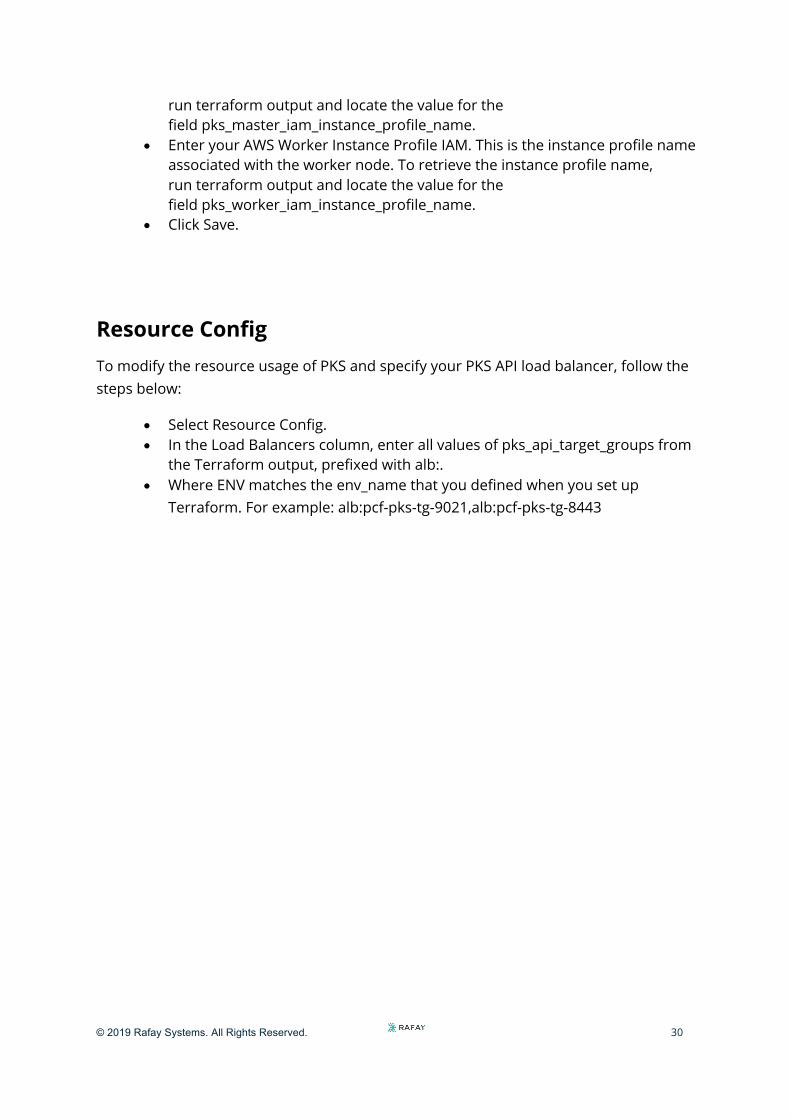
run terraform output and locate the value for the field pks_master_iam_instance_profile_name.
• Enter your AWS Worker Instance Profile IAM. This is the instance profile name associated with the worker node. To retrieve the instance profile name, run terraform output and locate the value for the field pks_worker_iam_instance_profile_name.
• Click Save.
Resource Config To modify the resource usage of PKS and specify your PKS API load balancer, follow the steps below:
• Select Resource Config. • In the Load Balancers column, enter all values of pks_api_target_groups from
the Terraform output, prefixed with alb:. • Where ENV matches the env_name that you defined when you set up
Terraform. For example: alb:pcf-pks-tg-9021,alb:pcf-pks-tg-8443

© 2019 Rafay Systems. All Rights Reserved. 31
Apply Changes • Return to the Ops Manager Installation Dashboard. • Click Review Pending Changes. Select the product that you intend to deploy
and review the changes. • Click Apply Changes.
`

© 2019 Rafay Systems. All Rights Reserved. 32
Retrieve the PKS API Endpoint To retrieve the PKS API endpoint, do the following:
• Navigate to the Ops Manager Installation Dashboard. • Click the Pivotal Container Service tile. • Click the Status tab and locate the Pivotal Container Service job. The IP
address of the Pivotal Container Service job is the PKS API endpoint.
Installing the PKS CLI and Kubectl
The PKS and Kubernetes CLIs help you interact with your PKS-provisioned Kubernetes clusters and Kubernetes workloads. To install the CLIs, follow the instructions below:
PKS CLI
• Navigate to Pivotal Network and log in. • Click Pivotal Container Service (PKS). • Select your desired release version from the Releases dropdown. • Click PKS CLI. • Click PKS CLI - Linux to download the Linux binary. • Rename the downloaded binary file to pks. • On the command line, run the following command to make the PKS binary
executable:
• Move the binary file into your PATH.
Kubernetes CLI
• Navigate to Pivotal Network and log in. • Click Pivotal Container Service (PKS). • Click Kubectl CLIs. • Click kubectl CLI - Linux to download the kubectl binary. • Rename the downloaded binary to kubectl. • On the command line, run the following command to make the kubectl binary
executable: • Move the binary into your PATH. For example:
chmod +x pks
chmod +x kubectl
mv kubectl /usr/local/bin/kubectl

© 2019 Rafay Systems. All Rights Reserved. 33
Configuring the PKS API This topic describes how to configure access to the Pivotal Container Service (PKS) API.
• Locate your Ops Manager root CA certificate and copy the content into a file.
• Target your UAA server by running the following command:

© 2019 Rafay Systems. All Rights Reserved. 34
• To request a token from the UAA server:
© 2019 Rafay Systems. All Rights Reserved. 35
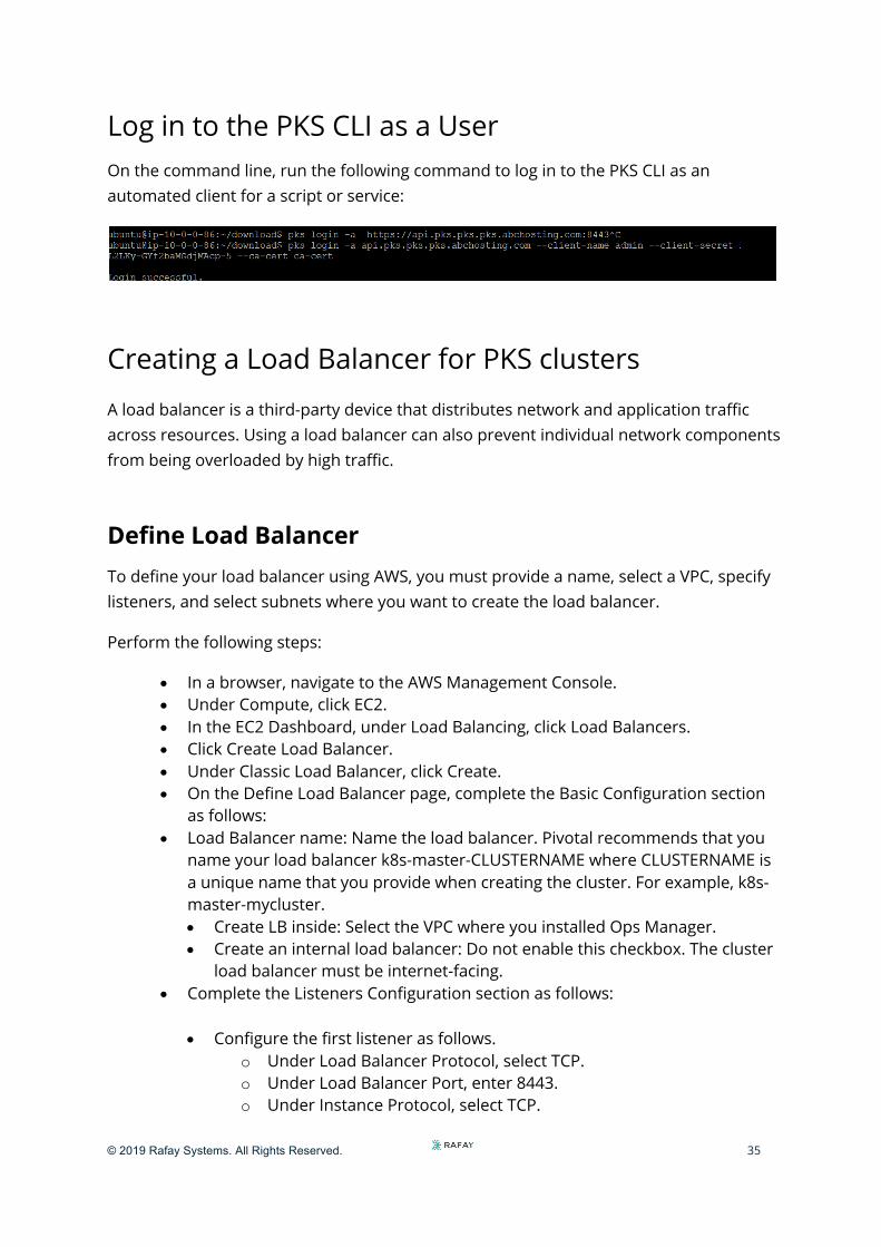
Log in to the PKS CLI as a User On the command line, run the following command to log in to the PKS CLI as an automated client for a script or service:
Creating a Load Balancer for PKS clusters
A load balancer is a third-party device that distributes network and application traffic across resources. Using a load balancer can also prevent individual network components from being overloaded by high traffic.
Define Load Balancer To define your load balancer using AWS, you must provide a name, select a VPC, specify listeners, and select subnets where you want to create the load balancer.
Perform the following steps:
• In a browser, navigate to the AWS Management Console. • Under Compute, click EC2. • In the EC2 Dashboard, under Load Balancing, click Load Balancers. • Click Create Load Balancer. • Under Classic Load Balancer, click Create. • On the Define Load Balancer page, complete the Basic Configuration section
as follows: • Load Balancer name: Name the load balancer. Pivotal recommends that you
name your load balancer k8s-master-CLUSTERNAME where CLUSTERNAME is a unique name that you provide when creating the cluster. For example, k8s-master-mycluster. • Create LB inside: Select the VPC where you installed Ops Manager. • Create an internal load balancer: Do not enable this checkbox. The cluster
load balancer must be internet-facing. • Complete the Listeners Configuration section as follows:
• Configure the first listener as follows. o Under Load Balancer Protocol, select TCP. o Under Load Balancer Port, enter 8443. o Under Instance Protocol, select TCP.

© 2019 Rafay Systems. All Rights Reserved. 36
o Under Instance Port, enter 8443. • Under Select Subnets, select the public subnets for your load balancer in the
availability zones where you want to create the load balancer.
• Click Next: Assign Security Groups.
Assign Security Groups
Perform the following steps to assign security groups:
• On the Assign Security Groups page, select one of the following: o Create a new security group: Complete the security group configuration as
follows: § Security group name: Name your security group. § Confirm that your security group
includes Protocol TCP with Ports 8443. o Select an existing security group: Select the default security group. The
default security group includes Protocol TCP with Ports 8443. • Click Next: Configure Security Settings.
Configure Security Settings
On the Configure Security Settings page, ignore the warning. SSL termination is done on the Kubernetes API.
Configure Health Check
Perform the following steps to configure the health check:
• On the Configure Health Check page, set the Ping Protocol to TCP. • For Ping Port, enter 8443. • Click Next: Add EC2 Instances.
Add EC2 Instances • Verify the settings under Availability Zone Distribution. • Click Add Tags.

© 2019 Rafay Systems. All Rights Reserved. 37
Creating a Kubernetes Cluster
Create a Kubernetes cluster using the AWS-assigned address of your load balancer as the external hostname when you run the pks create-cluster command.
To track cluster creation, run the following command:
Point the Load Balancer to All Master VMs • Locate the VM IDs of all master node VMs for your cluster. For information about
locating the VM IDs, see Identify Kubernetes Cluster Master VMs in Creating Clusters.
• Navigate to the AWS console. • Under EC2, select Load balancers. • Select the load balancer. • On the Instances tab, click Edit instances. • Select all master nodes in the list of VMs. • Click Save.
Scale the Cluster: Run the following command below to scale up your cluster.

© 2019 Rafay Systems. All Rights Reserved. 38
Deploying Nginx application
We are going to deploy our first application on Kubernetes .
Configure Your Workload • Open your workload’s Kubernetes service configuration file in a text editor. • To expose the workload through a load balancer, confirm that the Service
object is configured to be type: LoadBalancer. • For example:
• Confirm the workload’s Kubernetes service configuration is set to be type: LoadBalancer.
• Confirm the type property of each workload’s Kubernetes service is similarly configured.
Deploy and Expose Your Workload • To deploy the service configuration for your workload, run the following
command:
• This command creates three pod replicas, spanning three worker nodes.
• Deploy your applications, deployments, config maps, persistent volumes, secrets, and any other configurations or objects necessary for your applications to run.
--- apiVersion: v1 kind: Service metadata: labels: name: nginx name: nginx spec: ports: - port: 80 selector: app: nginx type: LoadBalancer ---
kubectl apply –f nginx.xml

© 2019 Rafay Systems. All Rights Reserved. 39
• Wait until your cloud provider has created and connected a dedicated load balancer to the worker nodes on a specific port.
Access Your Workload • To determine your exposed workload’s load balancer IP address and port
number, run the following command:
• Retrieve the load balancer’s external IP address and port from the returned listing.
• To access the app, run the following on the command:
Kubectl get svc nginx
Curl http://External-Loadbalancer-IP


