Application Note R11AN0463EU0200 Rev2.00 Page 1 of 42 Nov.11.21 Renesas RA Family Getting Started with the Graphics Application Introduction This application note describes creation of an application that uses Graphical User Interfaces with an EK-RA6M3G kit, referred to as ‘graphics application’. This application is geared towards providing a reference for developing complex multi-threaded applications with a touch screen graphical Human Machine Interface (HMI) by using the Renesas Flexible Software Package (FSP) and SEGGER AppWizard. Figure 1. Weather Panel of the Graphics Application on Renesas EK-RA6M3G This application is developed using the Renesas RA Flexible Software Package (FSP), which provides a quick and versatile way to build secure connected Internet of Things (IoT) devices using the Renesas RA family of Arm®-based microcontrollers (MCUs). RA FSP provides production ready peripheral drivers to take advantage of the RA FSP ecosystem along with SEGGER emWin library and FreeRTOS. In addition, Ethernet, USB, and file system stacks support are also available. This powerful suite of tools provides a comprehensive, integrated framework for rapid development of complex embedded applications. This application note assumes that you are familiar with the concepts associated with writing multi-threaded applications under a Real Time Operating System (RTOS) environment, such as FreeRTOS. This application note makes use of RTOS features such as threads and semaphores. Knowledge on operating these with FreeRTOS can help in understanding the supplied application project in source. For more detailed information on FreeRTOS features, refer to the FreeRTOS User Manual. The graphics application is developed using the Renesas e 2 studio Integrated Development Environment (IDE). This e 2 studio is a free application that you can download from the Renesas website. While building applications under the Renesas FSP Platform is considerably faster than developing similar applications in other environments, there is still a learning curve to understand the steps necessary to construct complex multi-threaded HMI applications quickly. This application note walks you through all the steps necessary, including the following: • Board setup • Application overview • Detailed explanation uses of the graphical screens • SEGGER AppWizard project integration • SEGGER AppWizard interactions setup • Adding an emWin widget that is not yet available in AppWizard • FSP configuration • Application design highlights • Using the General-Purpose Timer to drive a PWM backlight control signal • Importing, loading, and running the project.
Transcript
Application Note
R11AN0463EU0200 Rev2.00 Page 1 of 42 Nov.11.21
Renesas RA Family
Getting Started with the Graphics Application Introduction This application note describes creation of an application that uses Graphical User Interfaces with an EK-RA6M3G kit, referred to as ‘graphics application’. This application is geared towards providing a reference for developing complex multi-threaded applications with a touch screen graphical Human Machine Interface (HMI) by using the Renesas Flexible Software Package (FSP) and SEGGER AppWizard.
Figure 1. Weather Panel of the Graphics Application on Renesas EK-RA6M3G This application is developed using the Renesas RA Flexible Software Package (FSP), which provides a quick and versatile way to build secure connected Internet of Things (IoT) devices using the Renesas RA family of Arm®-based microcontrollers (MCUs). RA FSP provides production ready peripheral drivers to take advantage of the RA FSP ecosystem along with SEGGER emWin library and FreeRTOS. In addition, Ethernet, USB, and file system stacks support are also available. This powerful suite of tools provides a comprehensive, integrated framework for rapid development of complex embedded applications.
This application note assumes that you are familiar with the concepts associated with writing multi-threaded applications under a Real Time Operating System (RTOS) environment, such as FreeRTOS. This application note makes use of RTOS features such as threads and semaphores. Knowledge on operating these with FreeRTOS can help in understanding the supplied application project in source. For more detailed information on FreeRTOS features, refer to the FreeRTOS User Manual.
The graphics application is developed using the Renesas e2 studio Integrated Development Environment (IDE). This e2 studio is a free application that you can download from the Renesas website. While building applications under the Renesas FSP Platform is considerably faster than developing similar applications in other environments, there is still a learning curve to understand the steps necessary to construct complex multi-threaded HMI applications quickly. This application note walks you through all the steps necessary, including the following:
• Board setup • Application overview • Detailed explanation uses of the graphical screens • SEGGER AppWizard project integration • SEGGER AppWizard interactions setup • Adding an emWin widget that is not yet available in AppWizard • FSP configuration • Application design highlights • Using the General-Purpose Timer to drive a PWM backlight control signal • Importing, loading, and running the project.
Renesas RA Family Getting Started with the Graphics Application
R11AN0463EU0200 Rev2.00 Page 2 of 42 Nov.11.21
Required Resources Development tools and software
• e2 studio v2021-07 or greater • Renesas Flexible Software Package (FSP) v3.3.0 or greater • AppWizard V1.24_6.20 or greater Hardware
Renesas RA Family Getting Started with the Graphics Application
R11AN0463EU0200 Rev2.00 Page 4 of 42 Nov.11.21
1. Board Setup The EK-RA6M3G kit contains a few switch settings which must be configured prior to running the application associated with this application note. In addition to these switch settings, the boards also contain a USB debug port and connectors to access the J-Link® programming interface.
Table 1. Switch settings for EK-RA6M3G Switch Setting J8 Jumper on pins 1-2 J9 Open
Figure 2. J8 and J9 on EK-RA6M3 The EK-RA6M3G kit consists of two boards: the EK-RA6M3 board featuring the RA6M3 MCU with an on-chip Graphics LCD Controller and a Graphics Expansion Board featuring a 4.3-inch 480 x 272-pixel TFT color LCD with capacitive touch overlay. The GPIO port pin driving the backlight controller is capable of PWM output using a timer peripheral in the MCU. As a result, the intensity of the LED backlight can be adjusted by the RA6M3 MCU.
Figure 3. EK-RA6M3G Kit
Renesas RA Family Getting Started with the Graphics Application
R11AN0463EU0200 Rev2.00 Page 5 of 42 Nov.11.21
2. Application Overview One of the key goals of the provided graphics application is to demonstrate how to build applications which require complex HMI screens using SEGGER AppWizard and emWin library. The following list highlights all the key features of the graphics application:
• Complex HMI design using AppWizard • Multi-threaded applications using the FreeRTOS
In any software design, there are many ways to solve the same problem. The solution given in this application note is one approach.
2.1 RA6M3 MCU Peripherals used by the Graphics Application The graphics application is complex and it uses the Renesas RA6M3 MCU. This MCU is built around an Arm® Cortex®-M4 device. Developing complex microcontroller-based applications is usually a multi-step process:
1. The first step usually involves gathering the application requirements and performing a high-level system design that maps the requirements onto the set of hardware components. The components are necessary to fulfill those requirements including the target MCU that will be used in the design, the tool chains required to build/debug the applications, and so forth.
2. The next step usually determines which on-board peripherals of the target MCU are used. In this step, it is often necessary to spend a considerable amount of time understanding the register map of the on-board peripherals and writing lower level driver code necessary to expose the peripheral to the upper level application code. Most of this work has already been done in the FSP, considerably streamlining application development.
3. In addition to the on-board peripherals of the target MCU, the design often encompasses external hardware and how it is controlled. As an example, the EK-RA6M3G has the Graphics Expansion board, which is controlled directly by the on-chip Graphics LCD Controller (GLCDC) of the RA6M3 MCU.
4. The last step usually details how an application will be structured on top of the selected hardware to accomplish the initial requirements. The graphics application requirements were first mapped to the on-board peripherals of the EK-RA6M3G kit. Figure 4 shows all the internal hardware peripherals used by the graphics application. This application note describes how each of these peripherals is configured using the FSP, and the considerations that were used for each peripheral as the application is being developed.
Renesas RA Family Getting Started with the Graphics Application
R11AN0463EU0200 Rev2.00 Page 6 of 42 Nov.11.21
Figure 4. RA6M3 MCU Peripherals Used in the Graphics Application
2.2 Human-Machine Interface (HMI) In many HMI applications, the most daunting task may be the GUI itself. In applications requiring a graphical HMI, it is generally considered best practice to separate the business logic from presentation. This abstracts the GUI from making decisions on what to display. Instead, it is now only concerned about how to display it. It relies on external logic to tell it what to display and when to display it.
Once you have gathered the requirements, achieved a top-level design, and identified the hardware necessary to implement that design, it is often beneficial to construct a GUI (Graphical User Interface) to help quickly communicate the look and feel of the system to others. This is where the SEGGER AppWizard comes into play.
The FSP natively supports the use of AppWizard and emWin library from SEGGER. You may choose to use emWin primitive calls directly in your application or choose to use the AppWizard to design your screens. AppWizard is a stand-alone tool that provides a point and click environment for generating all the screens necessary for your embedded application. Once designed, the tool outputs .c and .h files, which you then include into your application. All the application screens in the graphics application were built using the AppWizard.
2.3 Graphics Application Panels The graphics application consists of two graphical panels, Weather Panel, and Logging Panel. In this application, we build separate static display designs for these two panels. The screen resolution on the EK-RA6M3G kit is 480 x 272 pixels.
Renesas RA Family Getting Started with the Graphics Application
R11AN0463EU0200 Rev2.00 Page 7 of 42 Nov.11.21
Figure 5. Screenshot of the Graphics Application Weather Panel This is the first screen that appears on the kit on boot up. It shows Weather
forecasts by selecting days or increase/decrease Temperature. Logging Panel Show events occurred in the Weather Panel, adjust LCD backlight, or text color
and background color of the Logging Editor.
3. AppWizard Overview This section provides an overview of how graphical screens are designed and integrated into an FSP application using the AppWizard and emWin library. It is not meant as a replacement for the AppWizard or emWin documentation. When designing graphical interfaces for the Renesas FSP platform, you are encouraged to refer the documentation for the AppWizard and emWin library.
The AppWizard presents a graphical point and click environment that allows you to quickly create all the screens needed for your embedded application. You can specify the screen resolution, color depth, and various other parameters such that what you see in the AppWizard that is running on your PC is what you will get on your embedded screens.
The AppWizard comes as a standard with some fonts and basic graphics for interfaces such as image, text, button, rotary, slider, etc. During your screen creation phase, you may provide the AppWizard with your own external images and font files to make your displays as fancy as needed.
Renesas RA Family Getting Started with the Graphics Application
R11AN0463EU0200 Rev2.00 Page 8 of 42 Nov.11.21
Figure 6. Screenshot of the Weather Panel being designed in the AppWizard The organization of the AppWizard is straightforward. The top center window, known as the Editor window, contains the screen being designed. On the upper left corner, you will find the Add Object window. This window shows the supported window objects in the AppWizard. It allows you to click on the object icons, and drag and place them in the Editor window. On the center left is Hierarchic Tree window. The order in which you add items in the same level/parent determines the order that they are drawn in the final screens, so some planning is necessary. However, you still can change the order by using drag and drop or the Move Up and Move Down buttons. As is the case with most graphical design environments, screens are laid out in a hierarchy where the main window is usually the parent and all graphical objects contained in the window are children of that parent. The Properties window on the right side displays properties associated with a selected object. You may select objects from the Hierarchic Tree window or from the Editor window.
The bottom left of the AppWizard screen contains Quick Access Buttons for managing resources such as Texts, Fonts, Images, animations and Variables you used to create and interact with the screens. AppWizard supports multi-language designs as well.
The key to making any graphical design interactive is to associate events like button touches with the event handling code that implements the appropriate functionality. The Interactions window on the bottom center make it easy for you to define the application’s behavior on certain actions. These interactions can be done without any extra code but AppWizard allows you to add your code to handle these actions and respond to GUI events.
Renesas RA Family Getting Started with the Graphics Application
R11AN0463EU0200 Rev2.00 Page 9 of 42 Nov.11.21
Figure 7. AppWizard Interactions Window
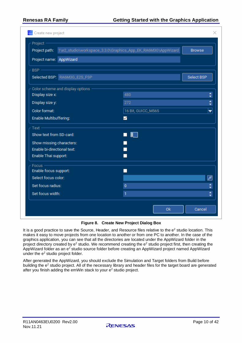
3.1 Create New Project Using the AppWizard This presents you with the Create New Project dialog box as shown in Figure 8. This dialog box is where you specify the project specific information such as the basic display settings as well as the path information for where AppWizard locates the files that result from the Export & Save process. The AppWizard also generates a simulation project in the folder \Simulation located in the project folder.
When you do Export & Save, the AppWizard creates .c and .h files that contain all the information necessary to render the screens you built with AppWizard on the LCD in your embedded application. The Project Path is where you specify the default output directory for the Source, Header, and Resource files.
Renesas RA Family Getting Started with the Graphics Application
R11AN0463EU0200 Rev2.00 Page 10 of 42 Nov.11.21
Figure 8. Create New Project Dialog Box It is a good practice to save the Source, Header, and Resource files relative to the e2 studio location. This makes it easy to move projects from one location to another or from one PC to another. In the case of the graphics application, you can see that all the directories are located under the AppWizard folder in the project directory created by e2 studio. We recommend creating the e2 studio project first, then creating the AppWizard folder as an e2 studio source folder before creating an AppWizard project named AppWizard under the e2 studio project folder.
After generated the AppWizard, you should exclude the Simulation and Target folders from Build before building the e2 studio project. All of the necessary library and header files for the target board are generated after you finish adding the emWin stack to your e2 studio project.
Renesas RA Family Getting Started with the Graphics Application
R11AN0463EU0200 Rev2.00 Page 11 of 42 Nov.11.21
Figure 9. AppWizard Project File View in the Graphics Application Folder Go to Project > Properties > C/C++ Build > Settings > GNU ARM Cross C Compiler > Includes to add the newly created AppWizard folder and its subfolders to the e2 studio project include path as shown in Figure 10.
Figure 10. Adding the AppWizard Folder to the e2 studio Project Include Path
Renesas RA Family Getting Started with the Graphics Application
R11AN0463EU0200 Rev2.00 Page 12 of 42 Nov.11.21
3.2 Design Weather Panel Buttons Using AppWizard The AppWizard User Manual and Quick Start Guide cover basic designs. The Weather Panel buttons, on the other hand, are more complex and are the target of this application note. These buttons grouped in a Window widget that including multiple objects. For example, the window ID_WINDOW_SUN consists of:
• ID_WINDOW_SUN Window widget. The place holder to group the other widgets.
• ID_MAGE_SUN_PRESSED Image widget. Visible when the ID_BUTTON_SUN pressed, invisible when the ID_BUTTON_SUN
released. Set bitmap using bottom_button_trans_pressed.png.
Text widget. Shows temperature range. • ID_BUTTON_SUN
Button widget. A transparent button without a bitmap image, placed on top of the other widgets. Some AppWizard interaction setups must be in place to create button pressed/release impression.
Renesas RA Family Getting Started with the Graphics Application
R11AN0463EU0200 Rev2.00 Page 13 of 42 Nov.11.21
Figure 14. Design of the SUN Button Group
3.3 Setup AppWizard Interactions Set the following interaction for the ID_BUTTON_SUN to create the button pressed/release as mentioned earlier in the Weather Panel Button Design section:
• The ID_IMAGE_SUN widget is invisible, toggling from visible to invisible when the transparent ID_BUTTON_SUN pressed.
• The ID_IMAGE_SUN widget is visible, toggling from invisible to visible when the transparent ID_BUTTON_SUN released.
Figure 15. ID_BUTTON_SUN Interaction When Clicked
Figure 16. ID_BUTTON_SUN Interaction When Released
3.4 Add emWin Widget to AppWizard Project You may need to use an emWin widget that is not yet supported by the AppWizard or need to create one in your custom code. The AppWizard allows that capability via the emWin API calls.
The Logging Panel in this graphics application features a Logging dialog created by using the Multiline Text widget.
Renesas RA Family Getting Started with the Graphics Application
R11AN0463EU0200 Rev2.00 Page 14 of 42 Nov.11.21
The steps to add an emWin widget to AppWizard project are as follows:
• Create an emWin widget by using emWin APIs in the slot routine for the AppWizard screen in the CustomCode folder.
• Handle GUI events/message if needed via slot routines in the file <ScreenID > _Slots.c located in the \AppWizard\Source\CustomCode folder.
• Figure 17 shows the function that creates the Multiline Text widget by using MULTIEDIT_CreateEx API and other APIs.
Figure 17. Adding Multiline Text Widget to AppWizard Application by using emWin APIs
4. Understanding the Graphics Application While the HMI is certainly a large part of understanding any HMI application, there are many other areas that you must understand while developing with the Renesas FSP applications. These include how the project is physically structured in e2 studio, how threads and thread resources are added to the project, how threads communicate, the state machine design, and how state data is shared among cooperating threads, and especially emWin thread.
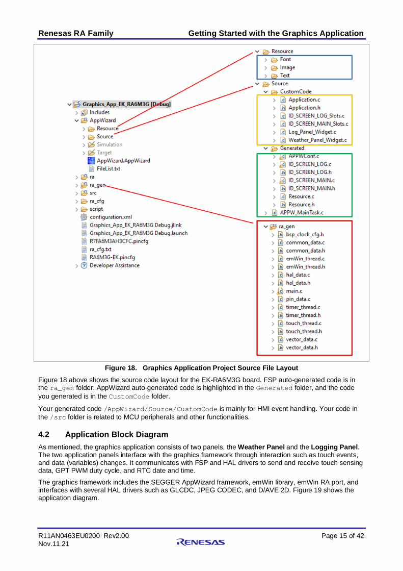
4.1 Source Code Layout Prior to diving into the actual application code, it is best to first understand the overall source code layout of an FSP project. Renesas FSP applications generally consist of two different types of code, your code, and auto-generated code. The auto-generated code can be further broken down into two sub-categories, code that is auto-generated by the FSP, and code that is auto-generated by AppWizard.
Renesas RA Family Getting Started with the Graphics Application
R11AN0463EU0200 Rev2.00 Page 15 of 42 Nov.11.21
Figure 18. Graphics Application Project Source File Layout Figure 18 above shows the source code layout for the EK-RA6M3G board. FSP auto-generated code is in the ra_gen folder, AppWizard auto-generated code is highlighted in the Generated folder, and the code you generated is in the CustomCode folder.
Your generated code /AppWizard/Source/CustomCode is mainly for HMI event handling. Your code in the /src folder is related to MCU peripherals and other functionalities.
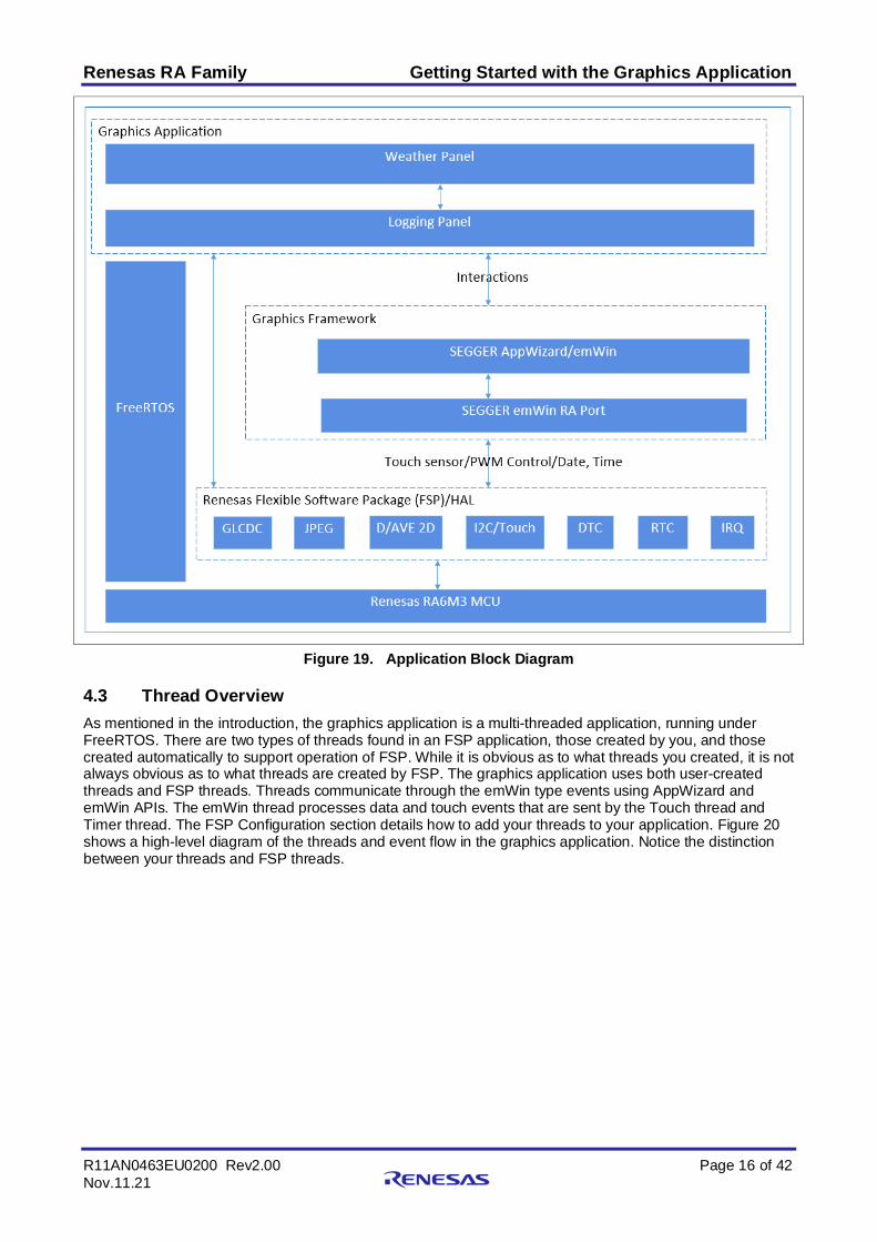
4.2 Application Block Diagram As mentioned, the graphics application consists of two panels, the Weather Panel and the Logging Panel. The two application panels interface with the graphics framework through interaction such as touch events, and data (variables) changes. It communicates with FSP and HAL drivers to send and receive touch sensing data, GPT PWM duty cycle, and RTC date and time.
The graphics framework includes the SEGGER AppWizard framework, emWin library, emWin RA port, and interfaces with several HAL drivers such as GLCDC, JPEG CODEC, and D/AVE 2D. Figure 19 shows the application diagram.
Renesas RA Family Getting Started with the Graphics Application
R11AN0463EU0200 Rev2.00 Page 16 of 42 Nov.11.21
Figure 19. Application Block Diagram
4.3 Thread Overview As mentioned in the introduction, the graphics application is a multi-threaded application, running under FreeRTOS. There are two types of threads found in an FSP application, those created by you, and those created automatically to support operation of FSP. While it is obvious as to what threads you created, it is not always obvious as to what threads are created by FSP. The graphics application uses both user-created threads and FSP threads. Threads communicate through the emWin type events using AppWizard and emWin APIs. The emWin thread processes data and touch events that are sent by the Touch thread and Timer thread. The FSP Configuration section details how to add your threads to your application. Figure 20 shows a high-level diagram of the threads and event flow in the graphics application. Notice the distinction between your threads and FSP threads.
Renesas RA Family Getting Started with the Graphics Application
R11AN0463EU0200 Rev2.00 Page 17 of 42 Nov.11.21
Figure 20. Graphics Application Event Flow
4.3.1 emWin Thread The emWin thread is an HMI thread that initializes various services and resources used by the graphics application. Once this initialization is complete, the emWin thread processes touch events and window messages. If any of these inputs result in a change to the system state, the emWin invokes the AppWizard Slot routines, which are the callback routines, resulting in changes to the graphical HMI. The flowchart in Figure 21 gives the high-level view of the emWin Thread.
Figure 21. High-Level View of the emWin Thread
Renesas RA Family Getting Started with the Graphics Application
R11AN0463EU0200 Rev2.00 Page 18 of 42 Nov.11.21
4.3.2 Touch Thread A separate touch thread is created to read the touch sensor data. The touch sensor IC signals an event, such as a user interaction on the LCD screen, by toggling a pin connected to the MCU. In response, the touch thread reads the information from the touch sensor IC registers. Figure 21 shows the flowchart of the touch thread.
Figure 22. Touch Thread Flowchart
5. FSP Configuration One of the first things you must do when writing an FSP application is to configure the FSP. To properly configure the FSP, you must have detailed knowledge of both the software design that you will be implementing along with the specific hardware it will be running on. For the hardware, this includes the types of peripherals to be used on the hardware, the pins they are mapped to, if they are internal or external to the MCU, and so on. From the software perspective, you need to decide how many threads will be used, which threads need access to what hardware components, and what additional software objects like semaphores and queues, that each thread will require. Once you have this information, you will be ready to successfully configure the FSP for your specific application needs.
In thegGraphics application, the FSP configuration is stored in a file named configuration.xml. Double-clicking on this file brings up the RA Configuration tab for the project.
Figure 23. configuration.xml on the Project Plane
Renesas RA Family Getting Started with the Graphics Application
R11AN0463EU0200 Rev2.00 Page 19 of 42 Nov.11.21
When a project is built from scratch, this configuration tab is where you will perform the initial configuration of the FSP. As you can see in Figure 24, the RA Configuration pane contains a Summary tab highlighting the items you may configure along with a scrolling window that lists all the software components currently selected for this project. Below this scrolling window are tabs that allow you to tailor the FSP to the needs of your specific application.
For the purposes of this application note, we will highlight a few of the details of the FSP configuration such as SEGGER emWin, the r_glcdc driver, touch controller, and PWM timer as they pertain to the graphics application. For additional details, refer to the Renesas Flexible Software Package (FSP) User’s Manual on how to configure the FSP.
When you have configured the project appropriately, click the Generate Project Content, the green arrow button above the summary screen, to build all the auto-generated files necessary to implement the components you defined.
Figure 24. Summary of the Graphics Application Configuration
5.1 Components Tab Even though the Components tab is the last tab showing, it is one of the first things you should configure. Selecting components first makes them available in subsequent operations such as mapping hardware resources to specific threads in the Stacks tab. One of the advantages of the FSP is that it will only compile in the components you choose, thereby reducing the size of your overall application. As shown in Figure 25, components are broken down into several categories.
Renesas RA Family Getting Started with the Graphics Application
R11AN0463EU0200 Rev2.00 Page 20 of 42 Nov.11.21
Figure 25. Components Tab Categories You may expand any of the categories by clicking the arrow to the left of the category name.
The following table highlights the selections used for the graphics application.
Renesas RA Family Getting Started with the Graphics Application
R11AN0463EU0200 Rev2.00 Page 21 of 42 Nov.11.21
Table 2. Components Used in the Graphics Application
Category Component Version Description BSP ra6m3g_ek 3.3.0 RA6M3G-EK Board Support Package Files CMSIS CoreM 5.7.0+fsp.3.3.0 Arm CMSIS Version 5 - Core (M) Common fsp_common 3.3.0 Board Support Package Common Files GUI emWin 6.20.0+fsp3.3.0 SEGGER emWin Library HAL Drivers
r_drw 3.3.0 TES D/AVE 2D Port r_dtc 3.3.0 Data Transfer Controller r_glcdc 3.3.0 Graphics LCD Controller r_icu 3.3.0 External Interrupt r_iic_master 3.3.0 I2C Master Interface r_ioport 3.3.0 I/O Port r_jpeg 3.3.0 JPEG Codec r_rtc 3.3.0 Real Time Clock r_ioport 3.3.0 I/O Port
Middleware rm_emwin_port 3.3.0 SEGGER emWin RA Port RTOS FreeRTOS 10.4.3+fsp.3.3.0 FreeRTOS TES dave2d 3.8.0+fsp.3.3.0 TES DAVE 2D Drawing Engine
5.2 Stacks Tab The Stacks tab is where you can add and configure the threads that the FSP automatically creates for your
application. You define a new thread by clicking the button and then entering a unique name for your new thread. Once you add a new thread, you must define the modules that the thread will use along with any thread objects that will be used by your thread.
As an example, if you click the Threads panel and then single click on the emWin Thread, you should see something like the screen capture shown in Figure 26. This shows that the emWin thread requires multiple modules, for example, the GLCDC driver which is used to control the LCD screen on the Graphics expansion board of the EK-RA6M3G kit.
Renesas RA Family Getting Started with the Graphics Application
R11AN0463EU0200 Rev2.00 Page 22 of 42 Nov.11.21
Figure 26. emWin Thread Properties and Modules Used for the Graphics Application
You can add additional Modules to any thread by clicking the button. If you have chosen the appropriate components prior to adding Modules to your threads, you should not receive any errors. As an example, Figure 27 shows you how to add a GPT timer to the Timer Thread. The timer is added by choosing (+) New Stack > Driver > Timers > Timer Driver on r_gpt. If have not first preselected the appropriate component for a module that you select, the FSP automatically selects the component for you. If the FSP detects errors with the module addition, it prefaces the module with an error. You may examine the errors by hovering over the module name.
Renesas RA Family Getting Started with the Graphics Application
R11AN0463EU0200 Rev2.00 Page 23 of 42 Nov.11.21
Figure 27. Adding r_gpt driver
5.3 Thread Objects FreeRTOS supports various objects such as mutexes, queues, semaphores, and timers. In the Objects window, you will see that there are three semaphore objects, g_touch_semaphore, g_i2c_semaphore, g_timer_semaphore created for this application.
You can allocate additional thread objects by clicking on the button next to the Objects window. As you
can see in Figure 28, after clicking the button in the Objects window, you are presented with a drop-down list that allows you to add the standard thread objects supported by FreeRTOS.
Figure 28. Objects window
Renesas RA Family Getting Started with the Graphics Application
R11AN0463EU0200 Rev2.00 Page 24 of 42 Nov.11.21
Figure 29. g_touch_semaphore Properties
5.4 Module Configuration Once you have added a module to your project, you need to configure its properties. The properties are dependent on the module(s) that you have added. Use the Properties tab to configure them. The graphics application adds the r_glcd driver module as part of SEGGER emWin stack. This module is used to configure the GLCDC peripheral of the Renesas RA6M3 MCU.
5.4.1 GLCDC Configuration As you can see in Figure 30, selecting the g_display0 Display Driver on the g_glcdc module under the emWin Thread Modules dialog brings up the associated properties under the Properties tab. The first thing you will notice is that it is a lengthy list of properties within the module group. The module group is where you configure the GLCDC controller. These properties can be a bit daunting at first but can be broken down. First, you will notice a few broad categories inside the Module grouping.
• Name: The name given to this instance of the module g_display0 by default. • Interrupts: You set the Line Detect interrupt and other interrupts here. • Input: This block of module properties defines the input to the graphics controller, most notably, the
framebuffer name and the number of the framebuffers, the memory address where the frame buffer is located, and others.
• Output: This is the area where you define the output properties of the GLCD. This includes properties such as the total horizontal and video cycles, the active video cycles, both horizontal and vertical, front and back porch duration, and so on.
• TCON: You use these lines in conjunction with the Pins tab, to map the Horizontal Sync (Hsync), Vertical Sync (Vsync), and Data Enable signals. You can specify the LCD Panel clock divisor that divides the clock input to the GCLD. This divisor ratio currently ranges from 1/1 to 1/32.
• Color Correction: This is where you can add various levels of color correction, for example, brightness, contrast, and gamma, to your display. Color, contrast, and gamma correction of LCD screens are outside the scope of this application note, but this is the area where you would do that type of adjustment.
Renesas RA Family Getting Started with the Graphics Application
R11AN0463EU0200 Rev2.00 Page 25 of 42 Nov.11.21
Figure 30. GLCD Properties Configuration using the Properties Tab
5.4.2 TCON Configuration If you scroll down a little further in the Properties tab, you will see four TCON properties. One of these is associated with the Panel clock division ratio. This allows additional division of the pixel clock that is driven directly from the PLLOUT branch of the clock tree. The other three are associated with the LCD sync signals. These three signals can be confusing to new users, so how these signals map to the physical pins they are connected to, is discussed here.
Figure 31. TCON Configuration for EK-RA6M3G Kit To provide flexibility, the GLCD controller of the RA6M3 MCU provides two pin grouping options. Each option uses different pins on the MCU to drive the data lines connected to the LCD display. It is up to the hardware designer to pick the group of pins they want to use. Picking one or the other may free up MCU pins that are necessary in some other part of the hardware design.
Renesas RA Family Getting Started with the Graphics Application
R11AN0463EU0200 Rev2.00 Page 26 of 42 Nov.11.21
If you look at the schematics for the EK-RA6M3G kit, you can see the pins header for the LCD board. You will also notice the three pins connected to the sync signals that are highlighted in red. The data lines chosen by the hardware designer must match one of the two pin groupings available under the GLCD module.
Figure 32. EK-RA6M3G LCD-Specific Signals from the Schematics The easiest way to understand this is to go to the Pins tab in the RA Configuration. You will see selections for Ports, Peripherals, and Other Pins, as shown in Figure 33. If you expand the Peripherals dialog, you will see all the various MCU peripherals that can be configured from this screen.
If you scroll down to the Graphics:GLCDC entry and click to expand it, you will see two options GLCD0 Pin Group Selection A and GLCD0 Pin Group Selection B. For the EK-RA6M3G kit, the GLCD0 Pin Group Selection A selected to drive the LCD display.
Notice that TCON0 is associated with the Port 1 Pin 02 (P102). On the schematic (P102) we see that it is connected to HSYNC, which is the horizontal synchronization pin for this LCD screen. Referring to Figure 31, we see TCON0 has been selected to drive the HSYNC signal.
Renesas RA Family Getting Started with the Graphics Application
R11AN0463EU0200 Rev2.00 Page 27 of 42 Nov.11.21
Figure 33. Pin Configuration Tab If you look at all the LCD data lines such as LCD_DATA_DATA00, and the pins they are connected to, they should match the pins they are connected to on the schematic. Clicking on the arrow to the right of the pin brings you directly to the associated Pin Configuration dialog just as if you had selected the Ports Group, and then the specific port and pin that you are interested in.
Figure 34. LCD Pin Configuration Using Configurator
Renesas RA Family Getting Started with the Graphics Application
R11AN0463EU0200 Rev2.00 Page 28 of 42 Nov.11.21
For example, clicking on this arrow to the right of the LCD_TCON0 pin should bring you to the Pin Selection Screen that looks like Figure 35. Notice that the pin is appropriately set to the Peripheral mode. At the time of writing this application note, the pins default to no pull up, high drive capacity, and CMOS output type. Clicking on the arrow button to the right of this screen brings you back to the associated peripheral screen.
Figure 35. LCD_TCON0 Settings in Pin Selection window
5.4.3 Touch Controller Configuration The touch event on the LCD screen is sensed by the RA6M3 MCU external IRQ pin, and the touch sensor is read via I2C master.
As shown in Figure 38, the interrupt signal of the Touch Controller on the LCD screen connected to P206 on header J1 of the EK-RA6M3 board, which is MCU IRQ channel 0. The r_icu and r_iic_master drivers are added to a Touch Thread to handle the IRQ channel 0 and I2C Master Channel 2, respectively.
Figure 36. External Interrupt Configuration
Renesas RA Family Getting Started with the Graphics Application
R11AN0463EU0200 Rev2.00 Page 29 of 42 Nov.11.21
Figure 37. I2C Master Driver Configuration
Figure 38. Touch Controller Signals The EK-RA6M3G User Manual recommends the touch interrupt input must have the internal pull-up feature enabled. Use Ports Configuration for this setting instead of Peripherals Configuration.
Renesas RA Family Getting Started with the Graphics Application
R11AN0463EU0200 Rev2.00 Page 30 of 42 Nov.11.21
Figure 39. Touch Controller Interrupt Configuration Note: When creating a project from scratch, you must add the touch driver to your project by copying the
touch_ft5x06 folder in this application note project to the new project. Go to Project > Properties > C/C++ Build > Settings > GNU ARM Cross C Compiler > Includes to add its include path.
Figure 40. Backlight Control Pin on EK-RA6M3G
Figure 41. Add Touch Driver Folder to the List of Include Paths
5.4.4 PWM Configuration The LCD_BLEN signal (Blanking Enable), which is connected to the P603 on the RA6M3 MCU, is configuring in PWM mode to control the intensity of LCD backlight. Figure 42 shows an excerpt from the Graphics Expansion board schematic, which shows the LCD_BLEN signal connected to the backlight controller.
Renesas RA Family Getting Started with the Graphics Application
R11AN0463EU0200 Rev2.00 Page 31 of 42 Nov.11.21
Figure 42. Backlight Control Pin on EK-RA6M3G In Pin Configuration, set P603 as GTIOCA output of the GPT channel 7. The Pin Group Selection is set as mixed and the Operation Mode as GTIOCA or GTIOCB.
Figure 43. GPT PWM Channel 7 Pin Configuration The r_gpt in the Timer thread is set in PWM mode to modulate LCD backlight intensity. In this graphics application, moving a slider in the Logging Panel will generate a duty cycle percentage that will be calculated into the GPT timer period and written to the counter register.
Renesas RA Family Getting Started with the Graphics Application
R11AN0463EU0200 Rev2.00 Page 32 of 42 Nov.11.21
Figure 44. GPT Driver Configuration in PWM Mode Figure 45 and Figure 46 show the AppWizard configuration for the backlight slider. Its range limits are from 5 to 100. Some interactions and custom code are needed to control the duty cycle of PWM output as well.
Renesas RA Family Getting Started with the Graphics Application
R11AN0463EU0200 Rev2.00 Page 33 of 42 Nov.11.21
Figure 45. Slider Setup to Control LCD Backlight Intensity
6. Application Code Highlights This section details the highlights of the graphics application. The goal of the graphics application is to show you how to develop more complex multi-threaded HMI applications using the FSP, AppWizard, and emWin library.
The key goal of the FSP is to abstract much of the complexity of interfacing with various Renesas peripherals and to quickly get you to the point where you can simply focus on constructing more complex applications as quickly as possible.
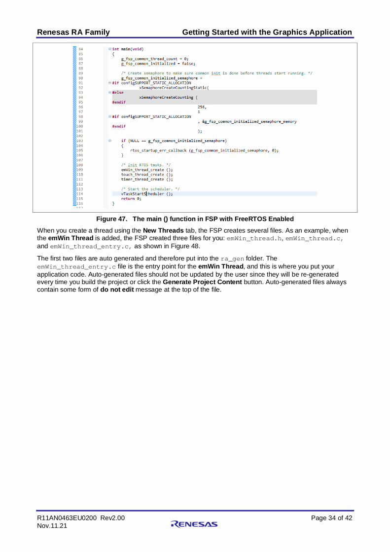
6.1 Threads and Main In the FSP, main() is an auto-generated file which looks like the following code. The threads and objects specified during the FSP configuration are initialized in the main().
Renesas RA Family Getting Started with the Graphics Application
R11AN0463EU0200 Rev2.00 Page 34 of 42 Nov.11.21
Figure 47. The main () function in FSP with FreeRTOS Enabled When you create a thread using the New Threads tab, the FSP creates several files. As an example, when the emWin Thread is added, the FSP created three files for you: emWin_thread.h, emWin_thread.c, and emWin_thread_entry.c, as shown in Figure 48.
The first two files are auto generated and therefore put into the ra_gen folder. The emWin_thread_entry.c file is the entry point for the emWin Thread, and this is where you put your application code. Auto-generated files should not be updated by the user since they will be re-generated every time you build the project or click the Generate Project Content button. Auto-generated files always contain some form of do not edit message at the top of the file.
Renesas RA Family Getting Started with the Graphics Application
R11AN0463EU0200 Rev2.00 Page 35 of 42 Nov.11.21
Figure 48. FSP Generated Source File Organization
6.1.1 AppWizard/emWin Initialization The FSP does not automatically initialize the AppWizard system. To initialize it, simply include GUI.h and add the MainTask() API call to emWin_thread_entry() located in the emWin_thread_entry.c file.
Figure 49. Backlight Control Pin on EK-RA6M3G
Renesas RA Family Getting Started with the Graphics Application
R11AN0463EU0200 Rev2.00 Page 36 of 42 Nov.11.21
6.1.2 emWin Events and Messages Touching the screen in the graphics application causes emWin to invoke the specific callback function generated for that screen in the AppWizard. AppWizard provides the callback function with specific information about the window that caused the event, and the actual event that occurred. These events are defined in WM.h.
You can add your code to slot routines in the file <ScreenID > _Slots.c located in the \AppWizard\Source\CustomCode folder to handle window events. The slot routines are actual callback routines generated by AppWizard. Since the <ScreenID > _Slots.c is updated whenever you add and generate new widgets or AppWizard interactions using AppWizard. Although custom code will be retained. It is a good practice to create your custom code in a separate file and call it in the appropriate slot routine.
Figure 50. Custom Code for The Slot Routine cb_ID_SCREEN_MAIN
6.1.3 AppWizard Variables Variables in the AppWizard can be used to store a value. They can be accessed and changed by the GUI or from outside of the GUI. The GUI can react on a change of a variable using interactions. One of typical uses is update the variables in a non-GUI thread to trigger data exchange between the AppWizard and non-GUI threads.
Renesas RA Family Getting Started with the Graphics Application
R11AN0463EU0200 Rev2.00 Page 37 of 42 Nov.11.21
Figure 51. AppWizard Variable Update in Timer Thread
Figure 52. Setup Interaction to perform Date, Time Update when ID_VAR_TIME_UPDATE is changed in AppWizard
7. Importing and Building the Project To bring the graphics application into the e2studio, follow these steps:
1. Launch e2 studio. 2. In the workspace launcher, browse to the workspace location of your choice. 3. Close the Welcome window. 4. In e2 studio, go to File > Import. 5. In the Import dialog box pick Existing Projects into Workspace. 6. Select archive file. 7. Select the Graphics_App_EK_RA6M3G project and click Finish. 8. Open configuration.xml. 9. Click on Generate Project Content on the FSP configurator window. 10. Now build the project.
8. Downloading the Executable to the EK-RA6M3G Kit To connect and run the code, follow these steps:
1. Connect your PC to the USB port next to the Ethernet jack silkscreened DEBUG using a USB cable. 2. Go to Run > Debug configurations. 3. Click Debug. The program will break at the reset handler. 4. Click Switch to the Debug perspective when prompted by the e2 studio. 5. Click Run > Resume. 6. The Weather Panel will show as in Figure 53. You can select forecast day or adjust the thermostat
temperature. Touch the top right corner to move to the Logging Panel.
Renesas RA Family Getting Started with the Graphics Application
R11AN0463EU0200 Rev2.00 Page 38 of 42 Nov.11.21
Figure 53. The Weather Panel The Logging Panel allows you to adjust the LCD backlight using the slider or change Logging Dialog text color and background color using the rotary and the switch, respectively. The logging buffer resets when it reaches the limit of 256 bytes. Touch the Renesas logo to go back to the Weather Panel.
Figure 54. The Logging Panel
9. e2 studio Tricks The e2 studio IDE has a handy feature that you can use to ensure that the images you are seeing on your LCD screen are coming from your framebuffer. To use this feature, make sure to connect the e2 studio to your board and run the program under the debugger. Ensure that your Memory tab is open in the Console window, normally located to the bottom of the screen in Debug view. Click the small green plus (+) sign in the Monitors Pane to add a memory monitor. You should see a Monitor Memory dialog as shown in . Enter the Framebuffer fb_background[0] or fb_background[1] and click the OK key.
A new tab should now appear under the Memory tab that displays the contents of the memory area you specified for the memory monitor.
Renesas RA Family Getting Started with the Graphics Application
R11AN0463EU0200 Rev2.00 Page 39 of 42 Nov.11.21
Figure 55. Using the Memory Monitor to Display the Framebuffer Contents You should now see the contents of the selected framebuffer memory area displayed in the memory monitor you just created. If you know what the hex value of every pixel should be on your display, you would be able to use this memory monitor to definitively say that your image is being stored in the framebuffer. However, as most of us do not know the hex values associated with our pixels, we will let the memory monitor do the work for us.
Figure 56. Framebuffer 1 Contents Select the New Renderings tab next to the memory monitor you just created, select Raw Image type from the list of options, and press the Add Rendering(s) button off to the right side of the screen.
Renesas RA Family Getting Started with the Graphics Application
R11AN0463EU0200 Rev2.00 Page 40 of 42 Nov.11.21
Figure 57. Rendering Format Selection The Raw Image Format dialog box appears, that lets you enter the screen resolution Width and Height, along with the Encoding that is 16 bpp (5:6:5), in our case.
Figure 58. Raw Image Format for Graphics Application on EK-RA6M3G Once you press the OK key, the memory monitor presents you with the image that would be displayed at that memory address, based on the parameters you entered.
Figure 59. Image Rendering Using Seen Using e2 studio Memory Monitor
Renesas RA Family Getting Started with the Graphics Application
R11AN0463EU0200 Rev2.00 Page 41 of 42 Nov.11.21
Website and Support Visit the following URLs to learn about key elements of the RA family, download components and related documentation, and get support.
RA Product Information www.renesas.com/ra RA Product Support Forum www.renesas.com/ra/forum RA Flexible Software Package www.renesas.com/FSP Renesas Support www.renesas.com/support
Notice 1. Descriptions of circuits, software and other related information in this document are provided only to illustrate the operation of semiconductor products
and application examples. You are fully responsible for the incorporation or any other use of the circuits, software, and information in the design of your product or system. Renesas Electronics disclaims any and all liability for any losses and damages incurred by you or third parties arising from the use of these circuits, software, or information.
2. Renesas Electronics hereby expressly disclaims any warranties against and liability for infringement or any other claims involving patents, copyrights, or other intellectual property rights of third parties, by or arising from the use of Renesas Electronics products or technical information described in this document, including but not limited to, the product data, drawings, charts, programs, algorithms, and application examples.
3. No license, express, implied or otherwise, is granted hereby under any patents, copyrights or other intellectual property rights of Renesas Electronics or others.
4. You shall not alter, modify, copy, or reverse engineer any Renesas Electronics product, whether in whole or in part. Renesas Electronics disclaims any and all liability for any losses or damages incurred by you or third parties arising from such alteration, modification, copying or reverse engineering.
5. Renesas Electronics products are classified according to the following two quality grades: “Standard” and “High Quality”. The intended applications for each Renesas Electronics product depends on the product’s quality grade, as indicated below. "Standard": Computers; office equipment; communications equipment; test and measurement equipment; audio and visual equipment; home
electronic appliances; machine tools; personal electronic equipment; industrial robots; etc. "High Quality": Transportation equipment (automobiles, trains, ships, etc.); traffic control (traffic lights); large-scale communication equipment; key
financial terminal systems; safety control equipment; etc. Unless expressly designated as a high reliability product or a product for harsh environments in a Renesas Electronics data sheet or other Renesas Electronics document, Renesas Electronics products are not intended or authorized for use in products or systems that may pose a direct threat to human life or bodily injury (artificial life support devices or systems; surgical implantations; etc.), or may cause serious property damage (space system; undersea repeaters; nuclear power control systems; aircraft control systems; key plant systems; military equipment; etc.). Renesas Electronics disclaims any and all liability for any damages or losses incurred by you or any third parties arising from the use of any Renesas Electronics product that is inconsistent with any Renesas Electronics data sheet, user’s manual or other Renesas Electronics document.
6. When using Renesas Electronics products, refer to the latest product information (data sheets, user’s manuals, application notes, “General Notes for Handling and Using Semiconductor Devices” in the reliability handbook, etc.), and ensure that usage conditions are within the ranges specified by Renesas Electronics with respect to maximum ratings, operating power supply voltage range, heat dissipation characteristics, installation, etc. Renesas Electronics disclaims any and all liability for any malfunctions, failure or accident arising out of the use of Renesas Electronics products outside of such specified ranges.
7. Although Renesas Electronics endeavors to improve the quality and reliability of Renesas Electronics products, semiconductor products have specific characteristics, such as the occurrence of failure at a certain rate and malfunctions under certain use conditions. Unless designated as a high reliability product or a product for harsh environments in a Renesas Electronics data sheet or other Renesas Electronics document, Renesas Electronics products are not subject to radiation resistance design. You are responsible for implementing safety measures to guard against the possibility of bodily injury, injury or damage caused by fire, and/or danger to the public in the event of a failure or malfunction of Renesas Electronics products, such as safety design for hardware and software, including but not limited to redundancy, fire control and malfunction prevention, appropriate treatment for aging degradation or any other appropriate measures. Because the evaluation of microcomputer software alone is very difficult and impractical, you are responsible for evaluating the safety of the final products or systems manufactured by you.
8. Please contact a Renesas Electronics sales office for details as to environmental matters such as the environmental compatibility of each Renesas Electronics product. You are responsible for carefully and sufficiently investigating applicable laws and regulations that regulate the inclusion or use of controlled substances, including without limitation, the EU RoHS Directive, and using Renesas Electronics products in compliance with all these applicable laws and regulations. Renesas Electronics disclaims any and all liability for damages or losses occurring as a result of your noncompliance with applicable laws and regulations.
9. Renesas Electronics products and technologies shall not be used for or incorporated into any products or systems whose manufacture, use, or sale is prohibited under any applicable domestic or foreign laws or regulations. You shall comply with any applicable export control laws and regulations promulgated and administered by the governments of any countries asserting jurisdiction over the parties or transactions.
10. It is the responsibility of the buyer or distributor of Renesas Electronics products, or any other party who distributes, disposes of, or otherwise sells or transfers the product to a third party, to notify such third party in advance of the contents and conditions set forth in this document.
11. This document shall not be reprinted, reproduced or duplicated in any form, in whole or in part, without prior written consent of Renesas Electronics. 12. Please contact a Renesas Electronics sales office if you have any questions regarding the information contained in this document or Renesas
Electronics products.
(Note1) “Renesas Electronics” as used in this document means Renesas Electronics Corporation and also includes its directly or indirectly controlled subsidiaries.
(Note2) “Renesas Electronics product(s)” means any product developed or manufactured by or for Renesas Electronics.
(Rev.4.0-1 November 2017)
Corporate Headquarters Contact information TOYOSU FORESIA, 3-2-24 Toyosu, Koto-ku, Tokyo 135-0061, Japan www.renesas.com
For further information on a product, technology, the most up-to-date version of a document, or your nearest sales office, please visit: www.renesas.com/contact/.
Trademarks Renesas and the Renesas logo are trademarks of Renesas Electronics Corporation. All trademarks and registered trademarks are the property of their respective owners.


![Learn how to [learn] LATEX€¦ · Outline Getting Started Basic Typesetting Miscellaneous Graphics Outline Getting Started Installing LATEX What is LATEX? Getting Help Basic Setup](https://static.documents.pub/doc/80x56/5f5714826011385604591983/learn-how-to-learn-latex-outline-getting-started-basic-typesetting-miscellaneous.jpg)


