The GPIB-232CT-A is warranted against defects in materials andworkmanship for a period of two years from the date of shipment, asevidenced by receipts or other documentation. National Instruments will, atits option, repair or replace equipment that proves to be defective during thewarranty period. This warranty includes parts and labor.
The media on which you receive National Instruments software arewarranted not to fail to execute programming instructions, due to defects inmaterials and workmanship, for a period of 90 days from date of shipment,as evidenced by receipts or other documentation. National Instruments will,at its option, repair or replace software media that do not executeprogramming instructions if National Instruments receives notice of suchdefects during the warranty period. National Instruments does not warrantthat the operation of the software shall be uninterrupted or error free.
A Return Material Authorization (RMA) number must be obtained from thefactory and clearly marked on the outside of the package before anyequipment will be accepted for warranty work. National Instruments willpay the shipping costs of returning to the owner parts which are covered bywarranty.
National Instruments believes that the information in this manual isaccurate. The document has been carefully reviewed for technical accuracy.In the event that technical or typographical errors exist, NationalInstruments reserves the right to make changes to subsequent editions ofthis document without prior notice to holders of this edition. The readershould consult National Instruments if errors are suspected. In no eventshall National Instruments be liable for any damages arising out of orrelated to this document or the information contained in it.
EXCEPT AS SPECIFIED HEREIN, NATIONAL INSTRUMENTS MAKES NOWARRANTIES, EXPRESS OR IMPLIED, AND SPECIFICALLY DISCLAIMSANY WARRANTY OF MERCHANTABILITY OR FITNESS FOR APARTICULAR PURPOSE. CUSTOMER'S RIGHT TO RECOVER DAMAGESCAUSED BY FAULT OR NEGLIGENCE ON THE PART OF NATIONALINSTRUMENTS SHALL BE LIMITED TO THE AMOUNT THERETOFOREPAID BY THE CUSTOMER. NATIONAL INSTRUMENTS WILL NOT BELIABLE FOR DAMAGES RESULTING FROM LOSS OF DATA, PROFITS,USE OF PRODUCTS, OR INCIDENTAL OR CONSEQUENTIAL DAMAGES,EVEN IF ADVISED OF THE POSSIBILITY THEREOF. This limitation of theliability of National Instruments will apply regardless of the form of action,whether in contract or tort, including negligence. Any action against
National Instruments must be brought within one year after the cause ofaction accrues. National Instruments shall not be liable for any delay inperformance due to causes beyond its reasonable control. The warrantyprovided herein does not cover damages, defects, malfunctions, or servicefailures caused by owner's failure to follow the National Instrumentsinstallation, operation, or maintenance instructions; owner's modification ofthe product; owner's abuse, misuse, or negligent acts; and power failure orsurges, fire, flood, accident, actions of third parties, or other events outsidereasonable control.
Copyright
Under the copyright laws, this publication may not be reproduced ortransmitted in any form, electronic or mechanical, including photocopying,recording, storing in an information retrieval system, or translating, inwhole or in part, without the prior written consent of National InstrumentsCorporation.
Trademarks
LabVIEW®, NI-488®, and NI-488.2™ are trademarks of NationalInstruments Corporation.
Product and company names listed are trademarks or trade names of theirrespective companies.
Warning Regarding Medical and Clinical Useof National Instruments Products
National Instruments products are not designed with components and testingintended to ensure a level of reliability suitable for use in treatment anddiagnosis of humans. Applications of National Instruments productsinvolving medical or clinical treatment can create a potential for accidentalinjury caused by product failure, or by errors on the part of the user orapplication designer. Any use or application of National Instrumentsproducts for or involving medical or clinical treatment must be performed byproperly trained and qualified medical personnel, and all traditional medicalsafeguards, equipment, and procedures that are appropriate in the particularsituation to prevent serious injury or death should always continue to beused when National Instruments products are being used. NationalInstruments products are NOT intended to be a substitute for any form ofestablished process, procedure, or equipment used to monitor or safeguardhuman health and safety in medical or clinical treatment.
FCC/DOC Radio FrequencyInterference Compliance
This equipment generates and uses radio frequency energy and, if notinstalled and used in strict accordance with the instructions in this manual,may cause interference to radio and television reception. This equipmenthas been tested and found to comply with the following two regulatoryagencies:
Federal Communications Commission
This device complies with Part 15 of the Federal CommunicationsCommission (FCC) Rules for a Class A digital device. Operation is subjectto the following two conditions:
1. This device may not cause harmful interference in commercialenvironments.
2. This device must accept any interference received, includinginterference that may cause undesired operation.
Canadian Department of Communications
This device complies with the limits for radio noise emissions from digitalapparatus set out in the Radio Interference Regulations of the CanadianDepartment of Communications (DOC).
Le présent appareil numérique n’émet pas de bruits radioélectriques dépassant leslimites applicables aux appareils numériques de classe A prescrites dans lerèglement sur le brouillage radioélectrique édicté par le ministère descommunications du Canada.
Instructions to Users
These regulations are designed to provide reasonable protection againstharmful interference from the equipment to radio reception in commercialareas. Operation of this equipment in a residential area is likely to causeharmful interference, in which case the user will be required to correct theinterference at his own expense.
There is no guarantee that interference will not occur in a particularinstallation. However, the chances of interference are much less if theequipment is installed and used according to this instruction manual.
If the equipment does cause interference to radio or television reception,which can be determined by turning the equipment on and off, one or moreof the following suggestions may reduce or eliminate the problem.
• Operate the equipment and the receiver on different branches of yourAC electrical system.
• Move the equipment away from the receiver with which it is interfering.
• Reorient or relocate the receiver’s antenna.
• Be sure that the equipment is plugged into a grounded outlet and thatthe grounding has not been defeated with a cheater plug.
Notice to user: Changes or modifications not expressly approved byNational Instruments could void the user’s authority tooperate the equipment under the FCC Rules.
If necessary, consult National Instruments or an experienced radio/televisiontechnician for additional suggestions. The following booklet prepared bythe FCC may also be helpful: How to Identify and Resolve Radio-TVInterference Problems. This booklet is available from the U.S. GovernmentPrinting Office, Washington, DC 20402, Stock Number 004-000-00345-4.
About This Manual ..........................................................................xiiiOrganization of This Manual ......................................................xiiiConventions Used in This Manual ............................................. xivRelated Documentation ..............................................................xviCustomer Communication ..........................................................xvi
GPIB-232CT-A Overview..........................................................1-1What You Need to Get Started................................................... 1-2Optional Equipment ....................................................................1-3Inspection ................................................................................... 1-3Hardware Description................................................................. 1-3Software Description ..................................................................1-4
Chapter 2Install Your Hardware ................................................................... 2-1
Step 1. Verify the Voltage Requirement ..................................2-1Step 2. Shut Down Your System..............................................2-1Step 3. Connect the Cables ....................................................... 2-2Step 4. Power On Your System and Switch On the
Chapter 3Install the NI-488.2 Software for MS-DOS ............................3-1
Main Programs and Files ............................................................3-1Additional Programs and Files ................................................... 3-2Terminology ............................................................................... 3-3Step 1. Run INSTALL ............................................................. 3-3
Step 2. Configure the Software ................................................3-5Step 3. Verify the Software Installation ................................... 3-6Step 4. Developing Your Application Program ....................... 3-7
Interactive Control Program (IBIC) ............................. 3-7Applications Monitor ................................................... 3-8The Application Program............................................. 3-8
Chapter 4Install the NI-488.2 Software for Windows ............................4-1
NI-488.2 Files for the Windows Operating Environment ..........4-1NI-488.2 Files for the Development of WindowsApplications................................................................................4-2GPIB Sample Windows Application Program ........................... 4-2Step 1. Run INSTALL ............................................................. 4-3
Step 2. Set Up the Windows Applications ............................... 4-5Step 3. Configure the Software ................................................4-5Step 4. Verify the Software Installation ................................... 4-5Using WIBIC ..............................................................................4-6Writing Windows Programs That Use the GPIB ....................... 4-7
The WINSAMP Sample............................................... 4-7General Rules for Using GPIB.LIB with Windows..... 4-8
Chapter 5Configure Your Software with IBCONF ................................5-1
Overview of IBCONF................................................................. 5-1Upper and Lower Levels of IBCONF ........................................5-3
Appendix DDLL Direct Entry NI-488 Functions andNI-488.2 Routines ............................................................................. D-1
Appendix EInterfacing to a Serial Device ....................................................... E-1
The RS-232C Standard............................................................... E-1Description of the RS-232 Port................................................... E-1Interfacing Serial Devices to the RS-232 Serial Port ................. E-3
Interfacing the GPIB-232CT-A to a DCE withHandshaking................................................................. E-3Interfacing the GPIB-232CT-A to a DCE withoutHandshaking................................................................. E-5
Interfacing the GPIB-232CT-A to a DTE withHandshaking................................................................. E-7Interfacing the GPIB-232CT-A to a DTE withoutHandshaking................................................................. E-9
Figure 5-1. Upper Level of IBCONF ................................................. 5-3Figure 5-2. Lower Level of IBCONF ................................................. 5-7
Figure A-1. Factory Default Setting (S Mode) for DIP Switch........... A-1
Figure E-1. Location of the RS-232 Connector ..................................E-3Figure E-2. Cable Configuration for 9-pin DTE to 9-pin DCE
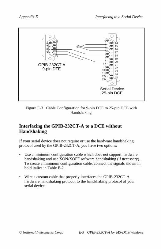
with Handshaking ............................................................E-4Figure E-3. Cable Configuration for 9-pin DTE to 25-pin DCE
with Handshaking ............................................................E-5Figure E-4. Minimum Configuration for 9-pin DTE to 9-pin DCE....E-6Figure E-5. Minimum Configuration for 9-pin DTE to
25-pin DCE ......................................................................E-6Figure E-6. Cable Configuration for 9-pin DTE to 9-pin DTE
with Handshaking ............................................................E-8Figure E-7. Cable Configuration for 9-pin DTE to 25-pin DTE
with Handshaking ............................................................E-8Figure E-8. Minimum Configuration for 9-pin DTE to 9-pin DCE ... E-9Figure E-9. Minimum Configuration for 9-pin DTE to
This manual contains instructions for installing and configuring the NationalInstruments GPIB-232CT-A RS-232-to-GPIB Controller and NI-488.2software for MS-DOS/Windows. This manual is meant to be used with theNI-488.2 Software Reference Manual for MS-DOS.
Organization of This Manual
This manual is organized as follows:
• Chapter 1, Introduction , contains a description of the GPIB-232CT-A,lists what you need to get started and optional equipment you can order,contains instructions for inspecting your GPIB-232CT-A, and giveshardware and software descriptions.
• Chapter 2, Install Your Hardware, contains instructions for connectingyour GPIB-232CT-A to a PC.
• Chapter 3, Install the NI-488.2 Software for MS-DOS, contains adescription of the programs and files included with the NI-488.2software for MS-DOS. This chapter also contains instructions forinstalling, configuring, and verifying your software as well asprogramming information on the IBIC program and the ApplicationsMonitor program.
• Chapter 4, Install the NI-488.2 Software for Windows , contains a list offiles that are copied to your destination and Windows directories whenyou install your software, and instructions for quick installation andinteractive installation of the NI-488.2 software for Windows. Thischapter also describes two methods you can use to communicate withGPIB devices from Windows: the Windows Interface Bus InteractiveControl (WIBIC) program and a Windows application program that youdevelop.
• Chapter 5, Configure Your Software with IBCONF , contains adescription of the programs IBCONF.EXE , a utility you can use toconfigure your NI-488.2 driver for MS-DOS, and WIBCONF.EXE , autility you can use to configure your NI-488.2 for Windows DLL.
• Appendix A, Hardware Configuration, describes how to configure theGPIB-232CT-A RS-232 serial port.
• Appendix B, Hardware Specifications , specifies the electrical,environmental, and physical characteristics of the GPIB-232CT-A andthe recommended operating conditions.
• Appendix C, Troubleshooting, suggests some areas to check if you haveproblems installing or using the GPIB-232CT-A or the NI-488.2software after going through the procedures described in Chapters 2through 5.
• Appendix D, DLL Direct Entry NI-488 Functions and NI-488.2Routines , explains and give examples of how to use the DLL DirectEntry NI-488 functions and NI-488.2 routines to access the GPIB.DLLfile. Following the examples are tables that list all NI-488.2 routinesand NI-488 functions, including their calling syntax and ordinal entryvalues.
• Appendix E, Interfacing to a Serial Device , describes the RS-232 serialport on the GPIB-232CT-A and explains how to interface a DCE orDTE serial device to the RS-232 serial port.
• Appendix F, Customer Communication, contains forms you can use torequest help from National Instruments or to comment on our productsand manuals.
• The Glossary contains an alphabetical list and description of terms usedin this manual including abbreviations, acronyms, metric prefixes,mnemonics, and symbols.
Conventions Used in This Manual
The following conventions are used in this manual.
bold italic Bold italic text denotes a note, caution, orwarning.
monospace Text in this font denotes text or characters thatare to be literally input from the keyboard,sections of code, programming examples, andsyntax examples. This font is also used for theproper names of disk drives, directories,programs, subprograms, subroutines, devicenames, functions, variables, field names, andfilenames.
italic monospace Italic text in this font denotes that you mustsupply the appropriate words or values in theplace of these items.
<> Angle brackets enclose the name of a key on thekeyboard–for example, <PageDown>.
<Enter> Key names are capitalized.
- A hyphen between two or more key namesenclosed in angle brackets denotes that youshould simultaneously press the named keys–forexample, <Control-C>.
IEEE 488 and IEEE 488 and IEEE 488.2 refer to theIEEE 488.2 ANSI/IEEE Standard 488.1-1987 and the
ANSI/IEEE Standard 488.2-1987, respectively,which define the GPIB.
RS-232 RS-232 refers to the ANSI/EIA-232-C standard.
Abbreviations, acronyms, metric prefixes, mnemonics, symbols, and termsare listed in the Glossary.
The following documents contain information that you may find helpful asyou read this manual:
• ANSI/EIA-232-C, Interface Between Data Terminal Equipment andData Circuit-Terminating Equipment Employing Serial Binary DataInterchange
• ANSI/IEEE Standard 488.1-1987, IEEE Standard Digital Interface forProgrammable Instrumentation
• ANSI/IEEE Standard 488.2-1987, IEEE Standard Codes, Formats, Protocols, and Common Commands
• Microsoft MS-DOS User’s Guide , Microsoft Corporation
• Microsoft Windows User’s Guide, Microsoft Corporation
Customer Communication
National Instruments wants to receive your comments on our products andmanuals. We are interested in the applications you develop with ourproducts, and we want to help if you have problems with them. To make iteasy for you to contact us, this manual contains comment and configurationforms for you to complete. These forms are in Appendix F, CustomerCommunication , at the end of this manual.
This chapter contains a description of the GPIB-232CT-A, lists what youneed to get started and optional equipment you can order, containsinstructions for inspecting your GPIB-232CT-A, and gives hardware andsoftware descriptions.
GPIB-232CT-A Overview
The GPIB-232CT-A is a high-performance serial-to-GPIB interface. Itprovides a computer with an RS-232 port, a means of controlling, talking,and listening on the GPIB. The GPIB-232CT-A is also capable ofinterfacing RS-232 instruments and peripherals to the GPIB.
The GPIB-232CT-A has all the software and logic required to implementthe physical and electrical specifications of the IEEE 488 and RS-232standards. It can interpret and execute high-level commands that you sendto it over the serial port, and perform GPIB-to-RS-232 protocol conversion.The GPIB-232CT-A also conforms to all versions of the IEEE 488standard, including IEEE 488.2. The NAT4882 Controller chip implementsall IEEE 488 Talker/Listener/Controller functionality.
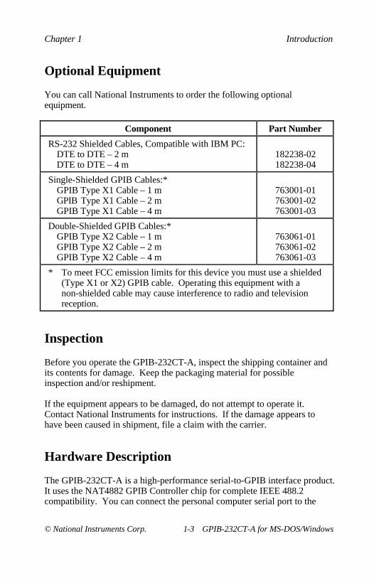
You can call National Instruments to order the following optionalequipment.
Component Part Number
RS-232 Shielded Cables, Compatible with IBM PC:DTE to DTE – 2 mDTE to DTE – 4 m
182238-02182238-04
Single-Shielded GPIB Cables:*GPIB Type X1 Cable – 1 mGPIB Type X1 Cable – 2 mGPIB Type X1 Cable – 4 m
763001-01763001-02763001-03
Double-Shielded GPIB Cables:*GPIB Type X2 Cable – 1 mGPIB Type X2 Cable – 2 mGPIB Type X2 Cable – 4 m
763061-01763061-02763061-03
* To meet FCC emission limits for this device you must use a shielded(Type X1 or X2) GPIB cable. Operating this equipment with anon-shielded cable may cause interference to radio and televisionreception.
Inspection
Before you operate the GPIB-232CT-A, inspect the shipping container andits contents for damage. Keep the packaging material for possibleinspection and/or reshipment.
If the equipment appears to be damaged, do not attempt to operate it.Contact National Instruments for instructions. If the damage appears tohave been caused in shipment, file a claim with the carrier.
Hardware Description
The GPIB-232CT-A is a high-performance serial-to-GPIB interface product.It uses the NAT4882 GPIB Controller chip for complete IEEE 488.2compatibility. You can connect the personal computer serial port to the
RS-232 port for controlling, talking, and listening on the GPIB. TheGPIB-232CT-A is also capable of interfacing RS-232 instruments andperipherals to the GPIB.
Software Description
NI-488.2 software is part of your GPIB-232CT-A kit. It is a comprehensiveset of programs and drivers for transforming the PC into a GPIB Controllerwith complete communications and bus management capability. TheNI-488.2 software also includes the Microsoft C, Microsoft BASIC,QuickBASIC, and BASICA language interfaces.
National Instruments has developed three other software applications youcan use with the GPIB-232CT-A and PC compatibles: LabVIEW forWindows, LabWindows® for DOS, and LabWindows/CVI.
LabVIEW for Windows is a software system with interactive graphics,state-of-the-art user interface concepts, and a powerful graphicalprogramming language. You must order LabVIEW separately.
LabWindows for DOS enhances Microsoft QuickBASIC and C with aninteractive development program, function panels to generate source code,and libraries for data acquisition, instrument control, data analysis, andpresentation. You must order LabWindows separately.
LabWindows/CVI extends the power of the LabWindows DOS version witha more extensive, full-function professional C programming environment forWindows. You must order LabWindows/CVI separately.
This chapter contains instructions for connecting your GPIB-232CT-Ato a PC.
The default hardware settings for the GPIB-232CT-A are compatible withthe default software settings. If you need more information or want tochange the defaults, follow the directions in Appendix A, HardwareConfiguration . If you change the hardware settings, make sure that you alsochange the software settings so that they are compatible.
Step 1. Verify the Voltage Requirement
The GPIB-232CT-A AC version is shipped from the factory with a100-120 V or 220-240 V internal power supply. The GPIB-232CT-A DCversion is shipped with a 100-120 V or 220-240 V, wall-mount or desktoppower supply.
Verify that the voltage marked on the GPIB-232CT-A or on the powersupply matches the voltage that is supplied in your area.
Caution: Operating the GPIB-232CT-A at any voltage other than the onespecified could damage the unit. Replacement fuses for the ACversion must be the proper type and size. Refer to Appendix B,Hardware Specifications , for fuse specifications.
Step 2. Shut Down Your System
Complete the following steps before connecting the cables:
1. Shut down your system.
2. Turn off your computer and unplug the power cord.
Complete the following steps to connect the cables.
1. Connect the serial cable to the GPIB-232CT-A 9-pin D-Sub connectorand securely fasten the holding screws. Connect the other end of thecable to your serial device. Be sure to use only shielded serial cables,and follow all RS-232 cabling restrictions.
2. Connect the GPIB cable to the GPIB-232CT-A 24-pin Champconnector and tighten the thumb screws on the connector. Connect theother end to your GPIB device(s). Be sure to follow all IEEE 488cabling restrictions, and use only shielded GPIB cables.
3. If you have an AC version, connect the power cord to the powerreceptacle on the front panel of the GPIB-232CT-A, then plug thesupply into an AC outlet of the correct voltage.
If you have a DC version, connect the DC power plug of the DC powersupply to the power jack on the serial end of the GPIB-232CT-A, thenplug the supply into an AC outlet of the correct voltage.
Step 4. Power On Your System and Switch On the GPIB-232CT-A
1. Plug the power cords for your computer system into a power outlet andpower on all devices.
2. If you have an AC version, use the front panel rocker switch to poweron your GPIB-232CT-A. If you have a DC version, use the powerswitch on the rear panel to power on your GPIB-232CT-A.
The POWER LED indicator should come on immediately. TheREADY LED indicator should come on after the GPIB-232CT-A haspassed its power-on self test, indicating the unit is ready for operation.If the READY LED does not come on within seven seconds after theunit is powered on, recheck all connections and switch settings andretry the power-on sequence. If the READY LED still does not comeon, refer to Appendix C, Troubleshooting, for information on areas tocheck if you have problems installing the GPIB-232CT-A.
This chapter contains a description of the programs and files included withthe NI-488.2 software for MS-DOS. This chapter also contains instructionsfor installing, configuring, and verifying your software as well asprogramming information on the IBIC program and the ApplicationsMonitor program.
Before installing the software, you should understand the files that willbe installed from the distribution disks and their purpose.
Main Programs and Files
You need the following programs and files to use the NI-488.2 software.
• GPIB.COM is the NI-488.2 driver that is loaded at system startup byMS-DOS.
• IBTEST.EXE is a program that you can use to test the NI-488.2software.
• IBCONF.EXE is a software configuration program. It can be used tochange the configuration of the NI-488.2 software.
• IBIC.EXE is an interactive control program that executes NI-488.2functions that you enter from the keyboard. It helps you learn thefunctions, program instruments or other GPIB devices, and developyour application program.
• APPMON.EXE is the applications monitor program. It is amemory-resident program that is useful in debugging your application.The applications monitor can halt program execution (trap) on returnfrom GPIB software calls, so that you can inspect function arguments,buffers, return values, GPIB global status variables, and other pertinentdata. The applications monitor performs automatic error detection.
Install the NI-488.2 Software for MS-DOS Chapter 3
• IBTRAP.EXE is a program that configures the applications monitor.
• ULI.COM is the Universal Language Interface software file you needto use the Universal Language Interface option of the NI-488.2software package.
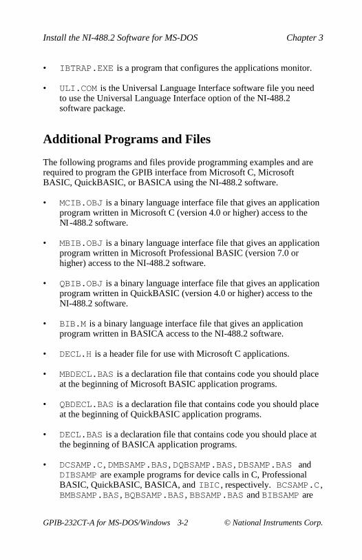
Additional Programs and Files
The following programs and files provide programming examples and arerequired to program the GPIB interface from Microsoft C, MicrosoftBASIC, QuickBASIC, or BASICA using the NI-488.2 software.
• MCIB.OBJ is a binary language interface file that gives an applicationprogram written in Microsoft C (version 4.0 or higher) access to theNI-488.2 software.
• MBIB.OBJ is a binary language interface file that gives an applicationprogram written in Microsoft Professional BASIC (version 7.0 orhigher) access to the NI-488.2 software.
• QBIB.OBJ is a binary language interface file that gives an applicationprogram written in QuickBASIC (version 4.0 or higher) access to theNI-488.2 software.
• BIB.M is a binary language interface file that gives an applicationprogram written in BASICA access to the NI-488.2 software.
• DECL.H is a header file for use with Microsoft C applications.
• MBDECL.BAS is a declaration file that contains code you should placeat the beginning of Microsoft BASIC application programs.
• QBDECL.BAS is a declaration file that contains code you should placeat the beginning of QuickBASIC application programs.
• DECL.BAS is a declaration file that contains code you should place atthe beginning of BASICA application programs.
• DCSAMP.C , DMBSAMP.BAS , DQBSAMP.BAS , DBSAMP.BAS andDIBSAMP are example programs for device calls in C, ProfessionalBASIC, QuickBASIC, BASICA, and IBIC , respectively. BCSAMP.C ,BMBSAMP.BAS , BQBSAMP.BAS , BBSAMP.BAS and BIBSAMP are
Chapter 3 Install the NI-488.2 Software for MS-DOS
example programs for board calls in C, Professional BASIC,QuickBASIC, BASICA, and IBIC , respectively.
• CSAMP488.C , MSAMP488.BAS , QBSAMP488.BAS ,BSAMP488.BAS , and SAMP488 are example programs for NI-488.2routines in C, BASIC, QuickBASIC, BASICA, and IBIC. Foradditional examples, refer to Chapter 4, NI-488.2 SoftwareCharacteristics and Routines , of the NI-488.2 Software ReferenceManual for MS-DOS.
ReadMe files are included on the distribution disk. ReadMe.DOC andReadMe.DOS discuss the NI-488.2 software. The remaining ReadMe filesdiscuss programming considerations for the supported languages.
Terminology
The term source disk or source directory refers to the NI-488.2 distributiondisk. The term destination directory refers to the location on your hard diskor disk where the software will be installed (usually C: \GPIB-CT ). Theterm boot drive refers to the drive that is read by your computer when youpower-on or restart your computer.
Step 1. Run INSTALL
The NI-488.2 distribution disk contains a program named INSTALL.EXEthat installs and tests the NI-488.2 software for you. You can install theNI-488.2 software using one of two methods: quick installation orinteractive installation.
Quick Installation
This quick version of the INSTALL program assumes that C : is your bootdrive. INSTALL copies files to the GPIB destination directory, namedC:\GPIB-CT and makes a change to your C:\CONFIG.SYS file.
Note: If your boot drive is not C :, or you do not want the defaultdestination directory to be created, you must install the NI-488.2software interactively. Refer to the following section, InteractiveInstallation, for more information.
Install the NI-488.2 Software for MS-DOS Chapter 3
After starting your computer, run the INSTALL program located on thedistribution disk by entering the following command:
X:install /q
where X is the name of the drive containing the distribution disk (usually Aor B).
The quick version of INSTALL copies the NI-488.2 files and thenautomatically modifies the C:\CONFIG.SYS file. If no error messageappears, the NI-488.2 software is successfully installed and you can proceedto Step 2. Configure the Software. If an error occurs during the quickinstallation, you may need to run the INSTALL program interactively, asdescribed in the next section. For more information on error codes, refer toChapter 3, Understanding the NI-488.2 Software, in the NI-488.2 SoftwareReference Manual for MS-DOS.
Interactive Installation
If you choose to interactively install the NI-488.2 software, complete thefollowing instructions.
After starting your computer, run the INSTALL program on the distributiondisk by entering the following command:
X:install
where X is the name of the drive containing the distribution disk (this isusually A).
This is the interactive version of the INSTALL program. When theprogram prompts you for the type of software to install (DOS or Windows),select DOS . After you select the DOS option, INSTALL displays a mainmenu with three options: Partial GPIB Installation , Full GPIBInstallation , and Return to DOS.
Select the type of installation that you want to use (Partial or Full). If youselect Partial GPIB Installation , you are prompted to choose which partsof the NI-488.2 software to install. If you select Full GPIB Installation ,all of the NI-488.2 software is installed.
Next, you are prompted to give your boot drive and the name of a newdirectory into which the files can be copied. The INSTALL program creates
Chapter 3 Install the NI-488.2 Software for MS-DOS
the specified destination directory and copies the files listed in the previoussection to their appropriate directories.
When the installation is complete, INSTALL asks to modify yourCONFIG.SYS file. If you enter yes , INSTALL adds the following line toyour CONFIG.SYS file:
device=dir\gpib.com
where dir is the directory to which INSTALL copied the NI-488.2software files; for example, dir may be C:\GPIB-CT . If you have aprevious version of the NI-488.2 software installed on your computer,INSTALL replaces the information in the old version file CONFIG.SYSwith the new information.
If you enter no to the above prompt, INSTALL displays a messageinforming you of the correct line that you should add to your CONFIG.SYSfile.
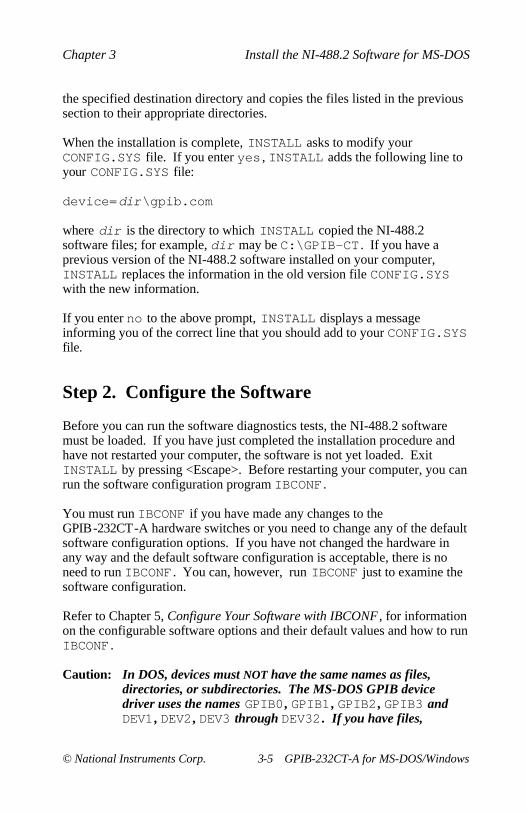
Step 2. Configure the Software
Before you can run the software diagnostics tests, the NI-488.2 softwaremust be loaded. If you have just completed the installation procedure andhave not restarted your computer, the software is not yet loaded. ExitINSTALL by pressing <Escape>. Before restarting your computer, you canrun the software configuration program IBCONF .
You must run IBCONF if you have made any changes to theGPIB-232CT-A hardware switches or you need to change any of the defaultsoftware configuration options. If you have not changed the hardware inany way and the default software configuration is acceptable, there is noneed to run IBCONF . You can, however, run IBCONF just to examine thesoftware configuration.
Refer to Chapter 5, Configure Your Software with IBCONF , for informationon the configurable software options and their default values and how to runIBCONF .
Caution: In DOS, devices must NOT have the same names as files,directories, or subdirectories. The MS-DOS GPIB devicedriver uses the names GPIB0 , GPIB1 , GPIB2 , GPIB3 andDEV1 , DEV2 , DEV3 through DEV32 . If you have files,
Install the NI-488.2 Software for MS-DOS Chapter 3
directories, or subdirectories with one these names, you mustrename them.
Step 3. Verify the Software Installation
To load the NI-488.2 software into the memory of the computer, you mustrestart the computer. You will typically only have to do this once when youfirst install the NI-488.2 software and whenever you need to reconfigure thehardware settings.
Restart your computer by pressing <Ctrl-Alt-Del>. This restarts thecomputer and loads the NI-488.2 software into memory.
After the NI-488.2 software is installed, run IBTEST . Running IBTESTensures that the NI-488.2 software is installed properly on your system.
Note: Before running IBTEST , make sure that the GPIB-232CT-A isnot connected to any GPIB devices.
If an error occurs, check the following:
• Is the GPIB-232CT-A connected to a GPIB device? IBTEST requiresthat the GPIB-232CT-A not be connected to any GPIB devices.
• Is the GPIB-232CT-A box powered on?
• Did you change any of the hardware configurations on theGPIB-232CT-A box? If so, check the current software configuration ofthe software by running IBCONF . Make sure that the hardwaresettings match. For more information, refer to Chapter 5, ConfigureYour Software with IBCONF .
• Has the CONFIG.SYS file on your startup disk been correctlymodified to contain the following line?
device=dir\gpib.com
where dir is the directory to which INSTALL copied the NI-488.2software files; for example, C:\GPIB-CT .
• Did you restart your computer after installing and configuring theNI-488.2 software? If not, restart your computer and run IBTESTagain.
Chapter 3 Install the NI-488.2 Software for MS-DOS
If you have performed these steps and there is still a problem, refer toAppendix C, Troubleshooting, for more information on installing or usingthe NI-488.2 software.
If no errors occurred, you can proceed to learn how to use the software andhow to develop your application program.
Step 4. Developing Your Application Program
There are two tools that are useful for developing your application program:IBIC.EXE and APPMON.EXE .
Interactive Control Program (IBIC)
The easiest way to learn to communicate with your instrument is bycontrolling it interactively. Located in your GPIB directory is the InterfaceBus Interactive Control program called IBIC.EXE . You can use thisprogram to communicate with your instrument; the program displays thestatus and any error after each NI-488.2 call.
With IBIC , you can program your instruments interactively from thekeyboard rather than from an application program. Using IBIC helps youquickly understand how the instruments and the NI-488.2 software work.IBIC is fully described in Chapter 6, IBIC, of the NI-488.2 SoftwareReference Manual for MS-DOS.
While running IBIC , you should study the descriptions of each functiongiven to fully understand their purpose or you can use the online helpavailable if you have questions.
To use IBIC.EXE , connect your instrument to the bus and enter thefollowing commands:
cd \dir
where dir is the name of the directory to which INSTALL copied theNI-488.2 software. By default, dir is c:\GPIB-CT .
IBIC
You are now ready to begin developing applications. Refer to Chapter 6,IBIC, of the NI-488.2 Software Reference Manual for MS-DOS to getstarted.
Install the NI-488.2 Software for MS-DOS Chapter 3
The program APPMON.EXE is the Applications Monitor. It is a DOSmemory-resident program that is used to monitor and record GPIB calls thatare made to the MS-DOS driver. It can also be used to halt the execution ofan application when a particular bit, for example, ERR, is set in ibsta .The Applications Monitor stores up to 255 previous GPIB calls and isinvaluable for debugging your application. The Applications Monitor isfully described in Chapter 7, Applications Monitor , of the NI-488.2Software Reference Manual for MS-DOS.
The Application Program
When you decide to write your application program, be sure to refer to theappropriate language reference manuals and the NI-488.2 SoftwareReference Manual for MS-DOS for the proper syntax of the functions. UseAPPMON.EXE and IBIC.EXE to help you develop your application.
This chapter contains a list of files that are copied to your destination andWindows directories when you install your software, and instructions forquick installation and interactive installation of the NI-488.2 software forWindows. This chapter also describes two methods you can use tocommunicate with GPIB devices from Windows: the Windows InterfaceBus Interactive Control (WIBIC ) program and a Windows applicationprogram that you develop.
Before installing the software, you should understand the files that will becopied from the distribution disk(s) and the purpose of each file. Thefollowing section describes the files contained on the distribution disk(s).
NI-488.2 Files for the Windows OperatingEnvironment
The following files are required to run a Windows application usingNI-488.2 routines. The INSTALL program copies these files to thespecified Windows directory.
• GPIB.DLL is a dynamic link library (DLL) that is accessed by aNI-488.2 application for Windows as the application executes. TheDLL contains all of the NI-488 functions and NI-488.2 routines.
• GPIB.INI is the private profile file which is used by GPIB.DLL todetermine the software configuration parameters for each GPIB boardand device in the system. You can modify GPIB.INI by using eitherthe WIBCONF.EXE file or a text editor.
Install the NI-488.2 Software for Windows Chapter 4
NI-488.2 Files for the Development of WindowsApplications
The following files are required to test and begin programming with yourNI-488.2 software. The INSTALL program copies the following files tothe specified destination directory.
• WIBCONF.EXE , a DOS application, is a software configurationprogram that you can use to change the software parameters and otherdata used by the DLL. It has the same basic functionality as theNI-488.2 for MS-DOS IBCONF program, which is described inChapter 5, Configure Your Software with IBCONF .
• WIBCONF.PIF , a Windows application, contains program informationabout the WIBCONF.EXE program that Windows uses when it runsWIBCONF.EXE .
• WIBTEST.EXE , a Windows application, is a program that tests thesoftware installation. It verifies that the software configuration isconsistent with the GPIB hardware configuration settings.
• WIBIC.EXE , a Windows application, is the Windows Interface BusInteractive Control program that executes NI-488 functions andNI-488.2 routines that you enter from the keyboard. It can help youlearn how to use the NI-488 functions and NI-488.2 routines, programinstruments or other GPIB devices, and develop your particularWindows application program.
GPIB Sample Windows Application Program
The following files are required to make the sample Windows application.The INSTALL program also copies the following files into a newsubdirectory, named C in the specified destination directory.
• GPIB.LIB is the import library for the DLL. You must link it to yourNI-488.2 application for Windows just like any other library.
• WINDECL.H is an include file that contains prototypes of the NI-488functions and NI-488.2 routines, and useful constants that you maywant to use in your NI-488.2 application for Windows. You mustinclude it at the beginning of any file that makes NI-488 function calls.
Chapter 4 Install the NI-488.2 Software for Windows
• WINSAMP.EXE is a compiled Windows application program forWindows that communicates over the GPIB. It is based primarily onthe GENERIC Windows application example provided with theWindows Software Development Kit.
• MAKEFILE is the makefile used to compile and link the sampleWindows application.
• WINSAMP.C is the C language source file containing the Windowsfunctions WinMain , MainWndProc , About , InitApplication ,and InitInstance .
• GPIBSAMP.C is the C language source file containing NI-488 functioncalls to the DLL.
• WINSAMP.H is the header file containing definitions and declarationsrequired by WINSAMP.C .
• WINSAMP.RC is the resource script file that defines the menus and thedialog-box template for the About dialog box.
• WINSAMP.DEF is the module definition file that contains moduledefinitions.
Step 1. Run INSTALL
You can install the NI-488.2 software for Windows using one of twomethods: quick installation or interactive installation.
Quick Installation
This quick version of the INSTALL program assumes that Windows isinstalled in the default directory (C:\WINDOWS). INSTALL copies files toC:\WINDOWS and the GPIB destination directory, named C:\GPIB-CTW .
Note: If Windows is not in its default directory or you do not want thedefault destination directory to be created, you must install theNI-488.2 software for Windows interactively. Refer to thefollowing section, Interactive Installation .
Install the NI-488.2 Software for Windows Chapter 4
After starting your computer, run the INSTALL program located on thedistribution disk by entering the following command:
X:install /qw
where X is the name of the drive containing the distribution disk (this isusually A).
The quick version of INSTALL copies the NI-488.2 files. If no errormessage appears, the NI-488.2 software is successfully installed and youcan proceed to Step 2. Set Up the Windows Applications. If an error occursduring the quick installation, you may need to run the INSTALL programinteractively, as described in the next section, Interactive Installation .
Interactive Installation
If you choose to interactively install the NI-488.2 software, complete thefollowing instructions.
After starting your computer, run the INSTALL program on the distributiondisk by entering the following command:
X:install
where X is the name of the drive containing the distribution disk (this isusually A).
This is the interactive version of the INSTALL program. When theprogram prompts you for the type of software to install (DOS or Windows),select Windows. After you select the Windows option, INSTALL displaysa main menu with three options: Partial GPIB Installation , Full GPIBInstallation , and Return to DOS.
Select the type of installation that you want to use (Partial or Full). If youselect Partial GPIB Installation , you are prompted to choose which partsof the NI-488.2 software to install. If you select Full GPIB Installation ,all of the NI-488.2 software is installed.
Next, you are prompted to give the location of your Windows directory andyou are prompted for the name of the directory where Windows is storedand the name of a new directory into which the files can be copied. TheINSTALL program creates the specified destination directory and copiesthe NI-488.2 files to the appropriate directories.
Chapter 4 Install the NI-488.2 Software for Windows
To set up the NI-488.2 applications for Windows, complete the followingsteps:
1. Run Windows Setup in the Main window.
2. Select Set Up Applications from the Options pull-down menu.
3. Add WIBIC and WIBTEST to the Windows Applications window.
Refer to the Microsoft Windows User’s Guide for a more detaileddescription of the Windows Setup procedure.
Step 3. Configure the Software
If you have made any changes to the GPIB-232CT-A hardware switches oryou need to change any of the default software configuration options, youmust run the program WIBCONF . If the default configuration of thehardware and software is acceptable, skip to Step 4. You can, however, runWIBCONF just to examine the software configuration.
Refer to Chapter 5, Configure Your Software with IBCONF , for informationon the configurable software options and their default values and how to runWIBCONF .
Step 4. Verify the Software Installation
The WIBTEST program verifies that the software is properly installed andconfigured for your GPIB-232CT-A. WIBTEST is a Windows applicationand can be run by selecting the WIBTEST icon in the WindowsApplications window.
WIBTEST requires no user interaction and takes about 10 seconds tocomplete. Disconnect any GPIB cables from the GPIB-232CT-A beforerunning the program. If an error occurs, check the following:
• Is the GPIB-232CT-A connected to a GPIB device? WIBTESTrequires that the GPIB-232CT-A not be connected to any GPIBdevices.
Install the NI-488.2 Software for Windows Chapter 4
• Did you change any of the hardware configurations on theGPIB-232CT-A? If so, check the current software configuration of thesoftware by running WIBCONF . Make sure that the hardware settingsmatch. Refer to Step 3. Configure the Software , earlier in this chapter.
• Are the files GPIB.DLL and GPIB.INI located in your Windowsdirectory (usually C:\WINDOWS)?
If you have performed these steps and there is still a problem, refer toAppendix C, Troubleshooting, for more information on installing theGPIB-232CT-A.
If no errors occur, you can proceed to learn how to use the software and howto develop your application program.
Using WIBIC
The easiest way to learn to communicate with your instrument is bycontrolling it interactively. Located in your GPIB directory is the InterfaceBus Interactive Control program called WIBIC.EXE . You can use thisprogram to communicate with your instrument; the program displays thestatus and any error after each NI-488.2 call.
With WIBIC , you can program your instruments interactively from thekeyboard rather than from an application program. Using WIBIC helps youquickly understand how the instruments and the NI-488.2 software work.The WIBIC program is the Windows version of the NI-488.2 software forMS-DOS IBIC program. It has the same general appearance and samefunction as the DOS IBIC program. Refer to Chapter 6, IBIC, of yourNI-488.2 Software Reference Manual for MS-DOS for a completedescription of how to use IBIC .
While running WIBIC , you should study the descriptions of each functiongiven to fully understand their purpose or you can use the online helpavailable if you have questions.
To run WIBIC , change to the Windows Applications window and selectthe WIBIC icon.
Chapter 4 Install the NI-488.2 Software for Windows
There are two methods for writing a Windows application that uses theGPIB. The first method is to write an application that uses the standardNI-488 functions and NI-488.2 routines and is linked to one of theWindows language interfaces. The NI-488.2 software includes theMicrosoft C language interface. Contact National Instruments forinformation on other language interfaces that you can use with Windows.
The second method of writing a NI-488.2 for Windows application is to usethe DLL direct entry NI-488 functions and NI-488.2 routines. Using directentry, you do not need to have a special language interface to link with yourapplication. Refer to Appendix D, DLL Direct Entry NI-488 Functions andNI-488.2 Routines, for more information.
The remainder of this chapter describes the WINSAMP sample program thatillustrates how GPIB calls can be made from a simple Microsoft CWindows application using the National Instruments Microsoft C languageinterface. It also lists a general set of rules to follow when using the DLL inyour own Windows application.
The WINSAMP Sample
There are two primary parts to the WINSAMP sample: WINSAMP.C andGPIBSAMP.C . WINSAMP.C handles most of the details for interfacingwith Windows and GPIBSAMP.C makes GPIB calls and then displays theresults on the screen.
To execute WINSAMP , set it up as a Windows application. Refer to Step 2.Set Up the Windows Applications , change to the Windows Applicationswindow, and select the WINSAMP icon.
To make changes to WINSAMP , add the desired changes and rebuild it byentering the following command.
make
Install the NI-488.2 Software for Windows Chapter 4
By following these general rules, any application can use the GPIB.DLL .
• Make the same GPIB calls that you do under DOS (refer to theNI-488.2 Software Reference Manual for MS-DOS for a list of thesecalls).
• Add GPIB.LIB to the library list in the link command line.
Note: All NI-488.2 GPIB.DLL files for Windows share the same.LIB file; therefore, you do not have to relink applicationsto switch between GPIB boxes.
• Ensure that the correct GPIB.DLL is in the directory in whichWindows is installed or in the DOS search path when the application isrun. Unlike the GPIB.LIB file, GPIB.DLL files are unique for eachNational Instruments GPIB box or interface board.
• Ensure that GPIB.INI is in the directory in which Windows isinstalled when the application is run so that it can be used to properlyinitialize the GPIB.DLL file. The GPIB.INI file is also unique foreach GPIB box or interface board.
This chapter contains a description of the programs IBCONF.EXE , a utilityyou can use to configure your NI-488.2 driver for MS-DOS, andWIBCONF.EXE , a utility you can use to configure your NI-488.2 driver forWindows DLL.
In this chapter, the term IBCONF is used to refer to both IBCONF.EXE andWIBCONF.EXE . When you complete your software configuration usingIBCONF , you are ready to begin developing your application program. Ifyou need more information on IBCONF , refer to the online help screens inthe configuration utility.
Note: Throughout this chapter and IBCONF , the terms interface board ,access board, and board are used to refer the GPIB-232CT-A.
Overview of IBCONF
IBCONF is a screen-oriented, interactive program that is used to modify theconfiguration parameters for your GPIB-232CT-A and the GPIB devicesconnected to it.
When used interactively, IBCONF reads in the GPIB configurationparameters and displays them for your inspection. You can alter any of theparameters to suit your requirements. When you have finished modifyingthe configurable parameters, these changes can be saved when you exit theIBCONF program.
In DOS, changes to the device driver using IBCONF.EXE take effect in thememory-resident device driver in two ways:
• The traditional method is to restart your computer so that DOS canreload the modified device driver into memory.
• A second, easier method, is to let IBCONF.EXE modify thememory-resident device driver when you exit IBCONF.EXE . Thissecond method works only if the two copies of the device driver (theone stored on disk and the one loaded into memory by DOS) arecompatible.
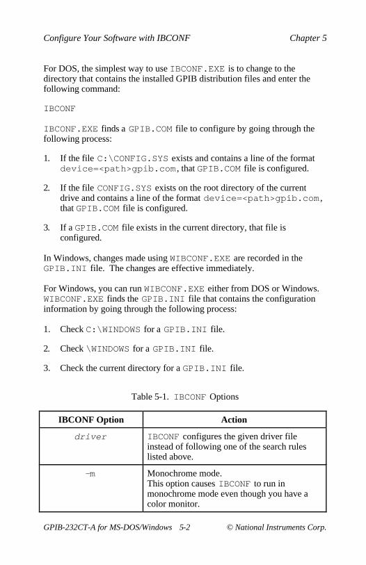
For DOS, the simplest way to use IBCONF.EXE is to change to thedirectory that contains the installed GPIB distribution files and enter thefollowing command:
IBCONF
IBCONF.EXE finds a GPIB.COM file to configure by going through thefollowing process:
1. If the file C:\CONFIG.SYS exists and contains a line of the formatdevice=<path>gpib.com , that GPIB.COM file is configured.
2. If the file CONFIG.SYS exists on the root directory of the currentdrive and contains a line of the format device=<path>gpib.com ,that GPIB.COM file is configured.
3. If a GPIB.COM file exists in the current directory, that file isconfigured.
In Windows, changes made using WIBCONF.EXE are recorded in theGPIB.INI file. The changes are effective immediately.
For Windows, you can run WIBCONF.EXE either from DOS or Windows.WIBCONF.EXE finds the GPIB.INI file that contains the configurationinformation by going through the following process:
1. Check C:\WINDOWS for a GPIB.INI file.
2. Check \WINDOWS for a GPIB.INI file.
3. Check the current directory for a GPIB.INI file.
Table 5-1. IBCONF Options
IBCONF Option Action
driver IBCONF configures the given driver fileinstead of following one of the search ruleslisted above.
-m Monochrome mode.This option causes IBCONF to run inmonochrome mode even though you have acolor monitor.
IBCONF operates at both an upper and a lower level. The upper levelconsists of the board device maps and gives a graphical picture of the GPIBsystem as defined in the handler. The lower level consists of screensdescribing the individual board and devices that make up the system.
Upper Level Device Map
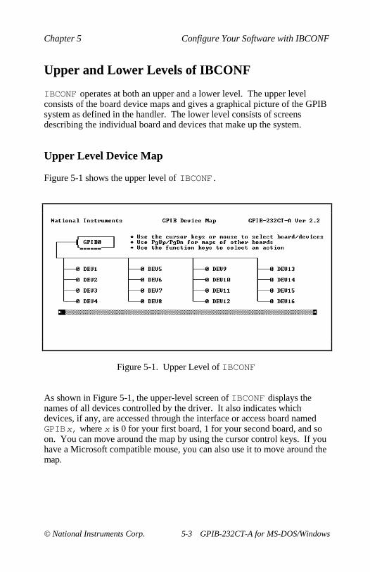
Figure 5-1 shows the upper level of IBCONF .
Figure 5-1. Upper Level of IBCONF
As shown in Figure 5-1, the upper-level screen of IBCONF displays thenames of all devices controlled by the driver. It also indicates whichdevices, if any, are accessed through the interface or access board namedGPIBx, where x is 0 for your first board, 1 for your second board, and soon. You can move around the map by using the cursor control keys. If youhave a Microsoft compatible mouse, you can also use it to move around themap.
Use <PageUp> or <PageDown> to toggle between the device maps for thedifferent GPIB boards. Each board is referred to as an access board byIBCONF . The maps show which devices are assigned to each box. Thedefault settings attach 16 devices to GPIB0 and 16 devices to GPIB1 .
Help
Use <F1> to access the comprehensive, online help feature of IBCONF .The help information describes the functions and common terms associatedwith the upper-level of IBCONF .
Rename
Use <F4> to rename a device. Move to the device you want to rename byusing the cursor control keys. Press <F4> and enter the new name of thedevice. The device name may contain up to eight characters and uses thesame rules as MS-DOS for naming files, except that suffixes (.xxx) are notallowed.
As specified by MS-DOS, the device name cannot use the followingcharacters:
. " / \ [ ] :| < > + = ; ,
(ASCII characters less than hex 21)
and cannot use the following reserved names:
CON NUL
Uppercase and lowercase letters are treated the same. The string PLOTTERis treated the same as the string plotter , for example. For this reason,IBCONF maps all lowercase letters to uppercase.
Caution: In DOS, devices must not have the same names as files,directories, or subdirectories. The MS-DOS GPIB devicedriver uses the names GPIB0 , GPIB1 , GPIB2 , GPIB3 andDEV1 , DEV2 , DEV3 through DEV32 . If you have files,directories, or subdirectories with one these names, you mustrename them.
The string representing a device or access board name is the first variableargument of the function ibfind called at the beginning of yourapplication program. Refer to Chapter 4, NI-488.2 Software Characteristicsand Routines, and Chapter 5, NI-488 Software Characteristics andFunctions , of the NI-488.2 Software Reference Manual for MS-DOS formore explanations of ibfind .
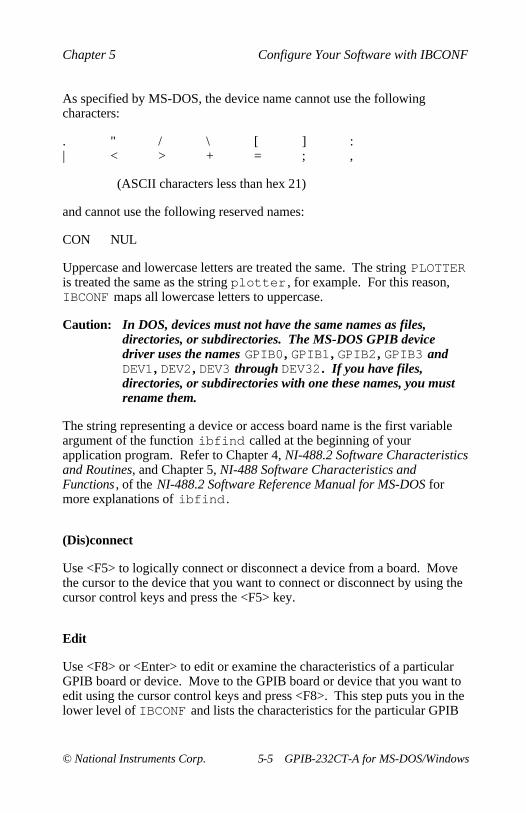
(Dis)connect
Use <F5> to logically connect or disconnect a device from a board. Movethe cursor to the device that you want to connect or disconnect by using thecursor control keys and press the <F5> key.
Edit
Use <F8> or <Enter> to edit or examine the characteristics of a particularGPIB board or device. Move to the GPIB board or device that you want toedit using the cursor control keys and press <F8>. This step puts you in thelower level of IBCONF and lists the characteristics for the particular GPIB
When configuring a GPIB device driver, you can write a text version of thedriver to a disk file. Use <F2> to direct IBCONF to create a text file namedGPIB.TXT in the current directory. This file contains a description of thecurrent GPIB driver and should be used only for information purposes.
Autoconfigure (IBCONF.EXE only)
Note: All the devices in the system must be connected and powered onbefore running Autoconfigure.
Use <F3> to cause IBCONF to perform its automatic configuration. Whenasked to autoconfigure a particular GPIB board, IBCONF interrogates allthe listen addresses on the GPIB to detect listening devices. IBCONF thenadjusts the device map for the board so that only the responding devices areconnected. It also adjusts the primary and secondary address fields of thedevices to match the addresses that responded as Listeners. The entireoperation only takes a few seconds. You may want to rename the connecteddevices with names that indicate their function. For more information onnaming devices, refer to the section, Rename, earlier in this chapter.
IBCONF disconnects devices from higher numbered interface boards toconfigure the current board. For this reason, if you have more than oneboard in your system, you should plan to autoconfigure all of them,beginning with board 0 and increasing. If you want to autoconfigure onlyone board, and leave the others alone, you should arrange for board 3 to bethe autoconfigured board, and for the others to be left alone.
Note: Do NOT use Autoconfigure if you are using LabWindows.
Exit
Use <F9> or <Escape> to exit IBCONF . If you have made changes,IBCONF asks if you want to save the changes to the disk before exiting.Type a y (yes) to save changes, n (no) to lose changes, or c (cancel) andremain in IBCONF . For more information on exiting IBCONF , refer to theExiting IBCONF section at the end of this chapter.
The lower level screens of IBCONF display the currently defined values forcharacteristics of a device or board, such as addressing and timeoutinformation, as shown in Figure 5-2. You access these screens from theupper level of IBCONF by selecting a board or device and pressing <F8> or<Enter>. The configuration settings selected for each device and eachboard are a means of customizing the communications and other optionsused with that board or device. The settings for devices specify thecharacteristics used by the access board for that device when devicefunctions are used. The settings for boards specify the characteristics usedwhen board functions are used.
The following functions are available at the lower level.
To change a specific characteristic of a device or a board, move the cursorto or click the mouse on that characteristic. You can also use <PageUp>,<PageDown>, <Home>, or <End> to move around the characteristics of adevice or a board. When the cursor is on the characteristic, either use theleft/right arrow keys to select between different options or input the optiondirectly from the keyboard. Instructions on the right side of the screeninform you which method is appropriate for the selected characteristic.
Change Board or Device
Use <Control-PageUp> and <Control-PageDown> to move to the next orprevious GPIB board or device in your configuration. For example, if youare editing DEV3 and press <Control-PageUp>, you will then be editingDEV4 .
Help
Use <F1> to access the comprehensive, online help feature of IBCONF .The help information describes the functions and common terms associatedwith the lower level of IBCONF .
Reset Value
Use <F6> to reset a characteristic option to its previous value.
Return to Map
At the lower level, <F9> or <Escape> returns you to the upper level devicemap of IBCONF .
The NI-488.2 software has factory default configurations. For example, thedefault device names of the 32 GPIB devices are DEV1 through DEV32 .You may want to change the names to more descriptive ones, such asMETER for a digital multimeter.
You can use IBCONF to look at the current default settings in the softwarefile.
If you do not use IBCONF to make changes to the NI-488.2 software, thedefault configurations of the software remain in effect.
Default Values
The following are the default values of the NI-488.2 software.
• There are 32 devices with symbolic names DEV1 through DEV32 .
• There are four access boards with symbolic names GPIB0 , GPIB1 ,GPIB2 , and GPIB3 . You cannot change access board names.
• Access board GPIB0 is enabled. GPIB1 , GPIB2 , and GPIB3 aredisabled.
• The GPIB addresses of the first 16 devices are the same as the devicenumber. For example, DEV1 is at address 1. These devices areassigned to the access board GPIB0 .
• The GPIB addresses of the second 16 devices are 1 through 16, inorder. For example, DEV17 is at address 1 and DEV18 is at address 2.These devices are assigned to access board GPIB1 .
• Each GPIB interface board is System Controller of its independent busand has a GPIB primary address of 0.
• The END message is sent with the last byte of each data message to adevice. No End-of-String (EOS) character is recognized.
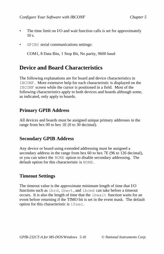
• The time limit on I/O and wait function calls is set for approximately10 s.
• GPIB0 serial communications settings:
COM1, 8 Data Bits, 1 Stop Bit, No parity, 9600 baud
Device and Board Characteristics
The following explanations are for board and device characteristics inIBCONF . More extensive help for each characteristic is displayed on theIBCONF screen while the cursor is positioned in a field. Most of thefollowing characteristics apply to both devices and boards although some,as indicated, only apply to boards.
Primary GPIB Address
All devices and boards must be assigned unique primary addresses in therange from hex 00 to hex 1E (0 to 30 decimal).
Secondary GPIB Address
Any device or board using extended addressing must be assigned asecondary address in the range from hex 60 to hex 7E (96 to 126 decimal),or you can select the NONE option to disable secondary addressing. Thedefault option for this characteristic is NONE .
Timeout Settings
The timeout value is the approximate minimum length of time that I/Ofunctions such as ibrd , ibwrt , and ibcmd can take before a timeoutoccurs. It is also the length of time that the ibwait function waits for anevent before returning if the TIMO bit is set in the event mask. The defaultoption for this characteristic is 10sec .
This timeout value controls the length of time the driver waits for a serialpoll response from a device. The ANSI/IEEE 488 standard does not specifythe length of time a Controller should wait for the response byte. The driverdefault of 1 s should work for most devices.
Terminate READ on EOS
Some devices send an EOS byte signaling the last byte of a data message.A yes response to this field causes the GPIB board to terminate a readoperation when it receives the EOS byte. The default option for thischaracteristic is no . See also the EOS Byte section.
Set EOI with EOS on Write
A yes response to this field causes the GPIB board to assert the EOI linewhen the EOS byte is detected on a write operation. The default option forthis characteristic is no . See also the EOS Byte section.
Type of Compare on EOS
This field specifies the type of comparison to be made with the EOS byte.You may indicate whether all eight bits are to be compared or just the sevenleast significant bits (ASCII or ISO format). This field is only valid if ayes response was given for either the Set EOI with EOS on Write field orthe Terminate Read on EOS field. The default option for this characteristicis 7-bit . See also the EOS Byte section.
EOS Byte
You can program some devices to terminate a read operation when aselected character is detected. A linefeed character (hex 0A) is a commonEOS byte.
Note: The driver does not automatically append an EOS byte to the endof data strings on write operations. You must explicitly includethis byte in your data string. The designation of the EOS byte is
only for the purpose of informing the driver of its value so thatI/O can terminate correctly.
The default option for this characteristic is 00H .
Set EOI at End of Write
Some devices, as Listeners, require that the Talker terminate a data messageby asserting the EOI line with the last byte. A yes response causes theGPIB interface board to assert the EOI line on the last data byte. Thedefault option for this characteristic is yes .
System Controller (Board Characteristic Only)
This field appears only on the board characteristics screen. The SystemController in a GPIB system is the device that maintains ultimate controlover the bus. There should only be one device designated as SystemController in any GPIB system. The default option for this characteristic isyes .
Assert REN when SC (Board Characteristic Only)
A yes response to this field causes Remote Enable (REN) to be assertedautomatically whenever the board is placed online, provided that the boardhas been given System Controller capability. If a no response is provided,an explicit call to ibsre is required to assert REN. The default option forthis characteristic is no .
Enable Auto Serial Polling (Board Characteristic Only)
This option enables or disables automatic serial polls of devices when theGPIB Service Request (SRQ) line is asserted. Positive poll responses arestored following the polls and can be read with the ibrsp device function.The default option for this characteristic is no .
If a device-level NI-488 call is made after control has been passed toanother device, enabling this protocol causes the board to assert SRQ with aSerial Poll status byte of hex 42. The current Controller must recognize thatthe board wants to regain control. If the current Controller passes controlback to the board, the device call proceeds as intended. If control is notpassed within the timeout period, the error ECIC results from the call. If theCIC protocol is disabled, ECIC is returned immediately if a device call ismade after control has been passed. The default option for thischaracteristic is no .
Bus Timing (Board Characteristic Only)
This field specifies the T1 delay of the source handshake capability for theboard. This delay determines the minimum amount of time, after the data isplaced on the bus, that the board may assert DAV during a write orcommand operation. If the total length of the GPIB cable length in thesystem is less than 15 m, then the value of 350nsec is appropriate.
There are other factors that may affect the choice of the T1 delay, althoughthey are unlikely to affect you. Refer to the ANSI/IEEE 488.2-1987Standard, IEEE Standard Codes, Formats, Protocols, and CommonCommands , for more information about these other factors.
Normally, devices are addressed before a read or write operation isperformed only if they are not already properly addressed for the read orwrite operation. If yes is selected, read or write operations alwaysreaddress even if the device is already properly addressed. The defaultoption is no .
Use This Interface (Board Characteristic Only)
If you do not want the driver to try to access an interface (because you donot have an interface in the system), select no for this option. When thisfield is set to no , the driver does not try to access the interface hardware. It
returns the error ENEB as soon as a program tries to access the board. Thedefault is yes for GPIB0 and no for all other GPIB boards.
COM Port (Board Characteristic Only)
This field specifies the serial communications port to which the GPIBinterface is connected. COM1 through COM4 define the standardPC-compatible serial communications ports. The Serial Port Base Addressand IRQ Level fields change accordingly when you change the COM PortSelection. If you have non-standard serial communications ports, thenmodify the Serial Port Base Address and IRQ level fields separately. Thedefault for GPIB0 is COM1 .
Serial Port Base Address (Board Characteristic Only)
This field specifies the base I/O address of the serial communications portand should only be used if you have a non-standard serial communicationsport. The GPIB-232CT-A software assumes that the serial controllerhardware is compatible with the National Semiconductor INS8250 universalasynchronous receiver/transmitter (the standard for PC-compatibles).
Serial Port IRQ Level (Board Characteristic Only)
This field specifies the IRQ level of the serial communications port andshould only be used if you have a non-standard serial communications port.The GPIB-232CT-A software assumes that the serial controller hardware iscompatible with the National Semiconductor INS8250 universalasynchronous receiver/transmitter (the standard for PC-compatibles).
Baud Rate (Board Characteristic Only)*
This field specifies the baud rate of the serial communications port. Itranges from 300 baud to 38400 baud. For Windows, 38400 baud is notsupported and 19200 baud does not work properly in all configurations; youshould use the default rate of 9600 baud.
This field specifies the parity checking for the serial communications port.Parity checking can be odd, even, or none; the default is none.
Stop Bits (Board Characteristic Only)*
This field specifies the number of stop bits per character for the serialcommunications port. Stop bits can be set to 1 or 2; the default is 1.
Data Bits (Board Characteristic Only)*
This field specifies the number of data bits per character for the serialcommunications port. The number of data bits can be set to 7 or 8; thedefault is 8.
* If you change these software settings, you must change your hardwaresettings to match. Refer to Appendix A, Hardware Configuration, formore information on changing these settings.
Exiting IBCONF
After you have made all your changes, you can exit IBCONF by pressing<F9> or <Escape>. The program asks if you want to save the changes tothe disk before exiting. Typing a y (yes) response causes the changes to bewritten to the file on disk.
Before exiting, the program checks for situations that can cause problems,such as the following:
• Is there a GPIB addressing conflict between a device and its accessboard?
• Are GPIB boards not present in the host machine at the specifiedaddress?
• Are timeouts disabled on a device or board?
If any of these situations are found, you are notified and given the option ofre-entering or exiting IBCONF .
This appendix describes how to configure the GPIB-232CT-A RS-232 serialport.
The default hardware settings for the GPIB-232CT-A are compatible withthe default software settings. If you change the hardware settings, makesure that you also change the software settings so that they are compatible.
Configure the RS-232 Serial Port
The GPIB-232CT-A is shipped from the factory configured to operate inSerial (S) mode. In S mode, the computer attached to the RS-232 port of theGPIB-232CT-A is the controlling device. The RS-232 serial port isconfigured at 9600 baud, 1 stop bit, no parity, and 8 data bits. To change theparameters, you set the configuration switches on the back panel.
The DIP switch is used to configure the serial port parameters of theGPIB-232CT-A while in S mode. In G mode, the GPIB-232CT-A is used tointerface an RS-232 device as a GPIB Talker/Listener.
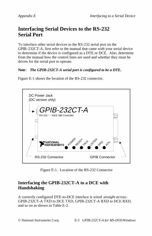
Figure A-1 shows the factory default setting of the DIP switch. InFigure A-1, the black side of the switch represents the position of the switchhandle.
S MODE DATA FORMAT
BAUD RATE OFF
GPIB ADDRESS G MODE
ON
Figure A-1. Factory Default Setting (S Mode) for DIP Switch
Note: For the purpose of this explanation, the switches have beenassigned numbers as a point of reference. These numbers doNOT appear on the GPIB-232CT-A itself. In this explanation,the three switches labeled BAUD RATE are switches 1 through3, the DATA FORMAT switches are switches 4 through 7, andthe S MODE switch is switch 8.
In Figure A-1, switches 1 through 3 are ON, OFF, and ON, respectively,indicating that the serial port is operating at 9600 baud. Switches 4 and 5are both OFF, which indicates that parity is disabled. Switch 6 is OFF,indicating 1 stop bit/character. Switch 7 is ON, indicating that theGPIB-232CT-A is using 8 bits per character for serial data transfers.Switch 8 is OFF, indicating that the GPIB-232CT-A is operating in S mode.
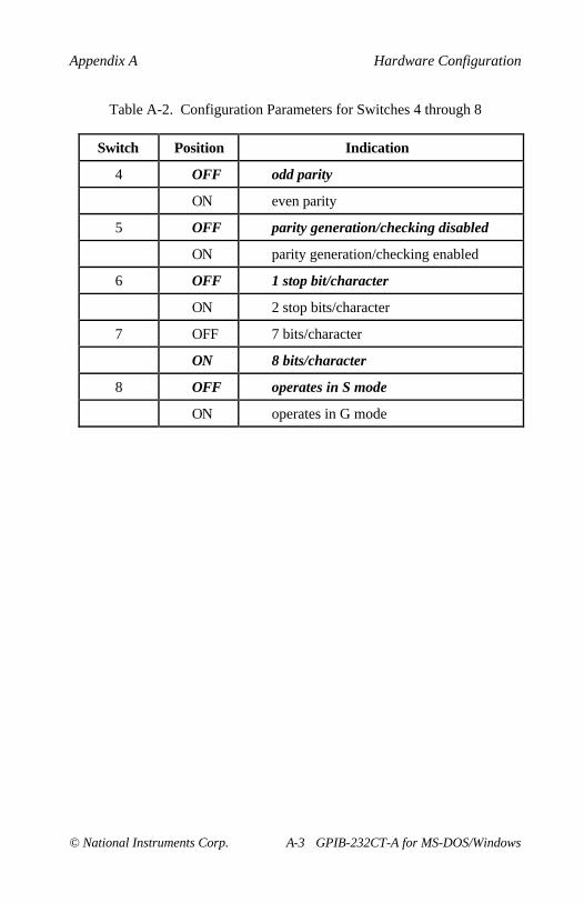
Tables A-1 and A-2 show the possible configurations of the eight switchesand what each configuration indicates. The factory default settings are inbold italics .
Table A-1. Configuration Parameters for Switches 1 through 3
This appendix suggests some areas to check if you have problems installingor using the GPIB-232CT-A or the NI-488.2 software after going throughthe procedures described in Chapters 2 through 5.
If you still have problems after completing the steps in this appendix,complete the appropriate forms in Appendix F, Customer Communicationand then contact National Instruments for technical support.
Troubleshooting Hardware Problems
Warning: The AC version of the GPIB-232CT-A contains circuitry thatoperates with hazardous voltages. Do NOT open the unitunless so instructed by National Instruments. Be sure toremove the power cord before opening the unit.
• All cables must be securely connected to the GPIB-232CT-A.
• Check the DIP switch settings on the GPIB-232CT-A. This DIP switchselects the serial port configuration. Most applications require thedefault setting, which is shown in Figure A-1. Refer to Appendix A,Hardware Configuration, for information on setting the GPIB-232CT-Aconfiguration using this switch.
• Make sure that the GPIB-232CT-A is powered on.
• If you have an AC version, check the fuse.
Warning: For continued protection against fire, replace only withthe same type and rating of fuse. See Appendix B,Hardware Specifications , for fuse specifications.
If the following three conditions apply, the GPIB-232CT-A and theNI-488.2 software are unable to communicate properly.
• GPIB calls return with the ERR bit set in ibsta .
• The value of iberr is EDVR.
• The value of ibcntl is 122541, 188077, or 253613 (1DEAD , 2DEAD ,or 3DEAD in hexadecimal notation).
The solution depends on the value of ibcntl . The following paragraphscontain troubleshooting tips for each of the ibcntl values.
• If ibcntl is 1DEAD , the software is unable to open and initialize theserial communications port. You should reconfigure yourGPIB-232CT-A and software to verify that the settings match.
• If ibcntl is 2DEAD , the software is encountering serial overrun errorswhen it attempts to access the GPIB-232CT-A box. Serial overrunerrors occur when the software is not able to service the serial interruptreceiving a serial byte before the next serial byte arrives. One way toeliminate this problem is to slow down the baud rate that theGPIB-232CT-A and NI-488.2 software are using. Another way toeliminate this problem is to unload any device drivers, TSRs, orapplications that you are using that might disallow interrupts over anextended period of time.
• If ibcntl is 3DEAD , there is total miscommunication between theNI-488.2 software and the GPIB-232CT-A. The only solution is topower off the box and restart the computer. If the problem persists, tryusing a different serial cable.
Appendix DDLL Direct Entry NI-488 Functionsand NI-488.2 Routines
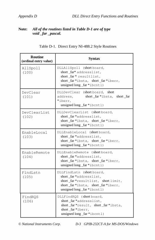
This appendix explains and gives examples of how to use the DLL DirectEntry NI-488 functions and NI-488.2 routines to access the GPIB.DLLfile. Following the examples are tables that list all NI-488.2 routines andNI-488 functions, including their calling syntax and ordinal entry values.
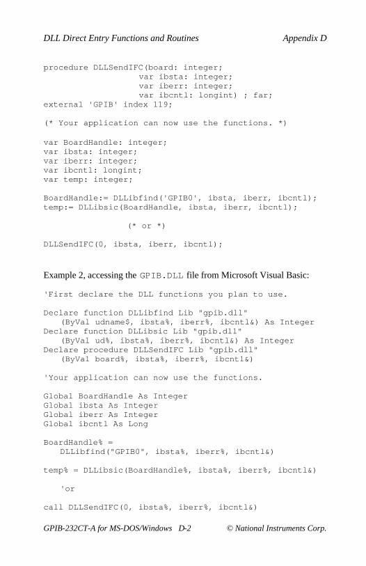
The DLL Direct Entry NI-488 functions and NI-488.2 routines can be usedto access the GPIB.DLL file from any language or programmingenvironment that runs under Windows and supports access to standardWindows DLL functions. As with all functions exported by a DLL, thesefunctions conform to the PASCAL calling conventions. A few examples ofusing these entry points follow. Tables D-1 and D-2 contain a complete listof all of the entry points.
For specific information on the variables ibsta , iberr , and ibcntl ,refer to Chapter 3, Understanding the NI-488.2 Software, in the NI-488.2Software Reference Manual for MS-DOS. For specific information on aroutine or function, refer to the NI-488.2 Software Reference Manual forMS-DOS. For information about accessing dynamic link library DLLfunctions from a given language or environment or using ordinal entryvalues which some environments do not support, see the documentationprovided with that package.
Example 1, accessing the GPIB.DLL file from Turbo Pascal for Windows:
(* First, import the DLL functions you plan to use. *)
Table D-1. Direct Entry NI-488.2 Style Routines (continued)
Routine(ordinal entry value)
Syntax
PassControl(107)
DLLPassControl (short board,short address, short _far *ibsta,short _far *iberr,unsigned long _far *ibcntl)
PPoll(108)
DLLPPoll (short board, short _far*result,
short _far *ibsta, short _far *iberr,unsigned long _far *ibcntl)
PPollConfig(109)
DLLPPollConfig (short board,short address, short dataline,short sense, short _far *ibsta,short _far *iberr,unsigned long _far *ibcntl)
PPollUnconfig(110)
DLLPPollUnconfig (short board,short _far *addresslist,short _far *ibsta, short _far *iberr,unsigned long _far *ibcntl)
RcvRespMsg(111)
DLLRcvRespMsg (short board,char _far *data, long count,short termination, short _far *ibsta,short _far *iberr,unsigned long _far *ibcntl)
ReadStatusByte(112)
DLLReadStatusByte (short board,short address, short _far *result,short _far *ibsta, short _far *iberr,unsigned long _far *ibcntl)
Receive(113)
DLLReceive (short board, short address,char _far *data, unsigned long count,short termination, short _far *ibsta,short _far *iberr,unsigned long _far *ibcntl)
(continues)
Appendix D DLL Direct Entry Functions and Routines
This appendix describes the RS-232 serial port on the GPIB-232CT-A andexplains how to interface a DCE or DTE serial device to the RS-232 serialport.
The GPIB-232CT-A transfers serial data using the electrical signals,mechanical connections, data format, and control protocols defined in theRS-232C standard. The RS-232 port on the GPIB-232CT-A provides anasynchronous serial communication link to a serial peripheral device.
The RS-232C Standard
The RS-232C standard (international standard CCITT V.24) was formulatedin 1969 largely from the efforts of the Electronic Industries Association(EIA) and Bell Laboratories. The standard describes the electricalspecifications and arrangement of control and data signals on both sides of aserial communications interface. Its original intent was to interfaceterminals to modems. Many manufacturers of computers and instrumentshave adopted the standard for their serial communications needs. For moreinformation on the RS-232C standard, contact
Global Engineering Documents7730 Carondelet Avenue, Suite 4007St. Louis, MO 63105(800) 854-7179
Description of the RS-232 Port
The RS-232 serial port on the GPIB-232CT-A uses a male 9-pinD-Subminiature connector with a DTE interface configuration. Table E-1shows the signal lines supported on the GPIB-232CT-A.
Table E-1. RS-232 Serial Port Signal Configuration
PinNumber
SignalDescription
RS-232Code
Function
2 RXD(Receive
Data)
BB This signal carries serial data fromthe serial device to theGPIB-232CT-A.
3 TXD(Transmit
Data)
BA This signal carries serial data fromthe GPIB-232CT-A to the serialdevice.
4 DTR (DataTerminalReady)
CD This signal is asserted by theGPIB-232CT-A to s ignal that it hasbeen powered on and is ready tooperate.
5 GND(Ground)
AB This signal establishes a referencepoint for all interface voltages.
7 RTS(Request to
Send)
CA This signal is driven by theGPIB-232CT-A. When asserted, itindicates that the GPIB-232CT-A isready to accept serial data. Whenunasserted, it indicates that theGPIB-232CT-A is no longer readyto accept serial data because thebuffer is full.
8 CTS (Clearto Send)
CB This signal is sensed by theGPIB-232CT-A. When asserted, itindicates that the serial device isready to accept serial data. Whenunasserted, it indicates that datatransmission should be disabled.
Interfacing Serial Devices to the RS-232Serial Port
To interface other serial devices to the RS-232 serial port on theGPIB-232CT-A, first refer to the manual that came with your serial deviceto determine if the device is configured as a DTE or DCE. Also, determinefrom the manual how the control lines are used and whether they must bedriven for the serial port to operate.
Note : The GPIB-232CT-A serial port is configured to be a DTE.
Figure E-1 shows the location of the RS-232 connector.
POWER
READY
TALK
LISTEN
SRQATN
GPIB-232CT-A IEEE 488 ControllerRS-232
NATIONAL INSTRUMENTS
RS-232 Connector GPIB Connector
DC Power Jack (DC version only)
Figure E-1. Location of the RS-232 Connector
Interfacing the GPIB-232CT-A to a DCE withHandshaking
A correctly configured DTE-to-DCE interface is wired straight across :GPIB-232CT-A TXD to DCE TXD, GPIB-232CT-A RXD to DCE RXD,and so on as shown in Table E-2.
Note : Connections in bold italics must be implemented.
Figure E-2 shows a properly configured 9-pin DTE to 9-pin DCE cableincluding the hardware handshake lines RTS, CTS, and DTR. With thisconfiguration, the GPIB-232CT-A can function properly (handshake) onbuffer full conditions. Figure E-3 shows an equivalent 9-pin DTE to 25-pinDCE cable configuration.
1
5
6 7 8 9
GPIB-232CT-A 9-pin DTE
5
1
9 8 7 6
Serial Device 9-pin DCE
Figure E-2. Cable Configuration for 9-pin DTE to 9-pin DCE withHandshaking
Figure E-3. Cable Configuration for 9-pin DTE to 25-pin DCE withHandshaking
Interfacing the GPIB-232CT-A to a DCE withoutHandshaking
If your serial device does not require or use the hardware handshakingprotocol used by the GPIB-232CT-A, you have two options:
• Use a minimum configuration cable which does not support hardwarehandshaking and use XON/XOFF software handshaking (if necessary).To create a minimum configuration cable, connect the signals shown inbold italics in Table E-2.
• Wire a custom cable that properly interfaces the GPIB-232CT-Ahardware handshaking protocol to the handshaking protocol of yourserial device.
The minimum configuration cable assumes that the DCE does not requireexternal hardware handshaking. The minimum configuration for a DTE9-pin to DCE 9-pin cable is shown in Figure E-4. Figure E-5 shows anequivalent 9-pin to 25-pin cable.
1
5
6 7 8 9
GPIB-232CT-A 9-pin DTE
5
1
9 8 7 6
Serial Device 9-pin DCE
Figure E-4. Minimum Configuration for 9-pin DTE to 9-pin DCE
1
5
6 7 8 9
GPIB-232CT-A 9-pin DTE
Serial Device 25-pin DCE
1
8 9 10 11 12 13
14 15 16 17 18 19 20 21 22 23 24 25
4 5 6
Figure E-5. Minimum Configuration for 9-pin DTE to 25-pin DCE
If your application requires a custom cable, you can construct one if youhave a thorough knowledge of the handshaking protocols involved. Reviewthe RS-232 characteristics of your serial device and build the cable toproperly connect the handshake lines of the two devices. Because theDTE-to-DCE connection is a straight across connection, it often involvesonly connecting RTS to RTS, CTS to CTS, DTR to DTR, and so on. If thedocumentation for your serial device does not provide a thoroughexplanation of its handshaking protocol, the ANSI/EIA-232-C standard is agood reference, provided your device conforms to the RS-232 protocol.
Caution: Although handshaking might not be required, it is best to usesome form of handshaking to prevent loss of data.
Interfacing the GPIB-232CT-A to a DTE withHandshaking
For serial devices set up as DTEs, you must wire a DTE-to-DTE interfacecable, commonly known as a null modem cable. The cable allows theGPIB-232CT-A to act as though it is communicating with a DCE, but itswaps the appropriate pins to achieve a DTE configuration. This wiringconfiguration is shown in Table E-3.
Figure E-6 shows a typical 9-pin to 9-pin null modem cable with the RTS,CTS, and DTR handshake lines implemented. Figure E-7 shows anequivalent 9-pin DTE to 25-pin DTE cable configuration.
The cable configuration in Figure E-6 allows you to connect to the 9-pinserial port of a personal computer. The cable in Figure E-7 shows how toconnect to the 25-pin serial port of a personal computer.
1
5
6 7 8 9
GPIB-232CT-A 9-pin DTE
5
1
9 8 7 6
Serial Device 9-pin DTE
Figure E-6. Cable Configuration for 9-pin DTE to 9-pin DTE withHandshaking
Serial Device 25-pin DTE
1
8 9 10 11 12 13
14 15 16 17 18 19 20 21 22 23 24 25
1
5
6 7 8 9
GPIB-232CT-A 9-pin DTE
Figure E-7. Cable Configuration for 9-pin DTE to 25-pin DTE withHandshaking
Interfacing the GPIB-232CT-A to a DTE withoutHandshaking
If your serial device does not require or use the same hardware handshakingprotocol used by the GPIB-232CT-A, you have two options:
• Use a minimum configuration null modem cable which does not supportthe hardware handshake lines and use XON/XOFF softwarehandshaking (if necessary). To create a minimum configuration cable,connect the signals shown in bold italics in Table E-3.
• Wire a custom cable that properly interfaces the GPIB-232CT-Ahardware handshaking protocol to the handshaking protocol of yourserial device.
Minimum Configuration Cable
The minimum cable configuration assumes that the serial device does notrequire external hardware handshaking. The minimum configuration for a9-pin to 9-pin null modem cable is shown in Figure E-8. Figure E-9 showsan equivalent 9-pin to 25-pin cable.
1
5
6 7 8 9
GPIB-232CT-A 9-pin DTE
5
1
9 8 7 6
Serial Device 9-pin DTE
Figure E-8. Minimum Configuration for 9-pin DTE to 9-pin DTE
Figure E-9. Minimum Configuration for 9-pin DTE to 25-pin DTE
Custom Cables
If your application requires a custom cable, you can construct one if youhave a thorough knowledge of the handshaking protocols involved. Reviewthe RS-232 characteristics of your serial device and build the cable toproperly connect the handshake lines of the two devices. If thedocumentation for your serial device does not provide a thoroughexplanation of its handshaking protocol, the ANSI/EIA-232-C standard is agood reference, provided your device conforms to the RS-232 protocol.
Caution: Although handshaking might not be required, it is best to usesome form of handshaking to prevent loss of data.
For your convenience, this appendix contains forms to help you gather theinformation necessary to help us solve technical problems you might haveas well as a form you can use to comment on the product documentation.Filling out a copy of the Technical Support Form before contactingNational Instruments helps us help you better and faster.
National Instruments provides comprehensive technical assistance aroundthe world. In the U.S. and Canada, applications engineers are availableMonday through Friday from 8:00 a.m. to 6:00 p.m. (central time). In othercountries, contact the nearest branch office. You may fax questions to us atany time.
Corporate Headquarters(512) 795-8248Technical support fax: (800) 328-2203
Technical support is available at any time by fax. Include the informationfrom your configuration form. Use additional pages if necessary.
Name
Company
Address
Fax ( ) Phone ( )
Computer brand
Model Processor
Operating system
Speed MHz RAM MB
Display adapter
Mouse yes no
Other adapters installed
Hard disk capacity MB Brand
Instruments used
National Instruments hardware product model
Revision
Configuration
National Instruments software product
Version
Configuration
(continues)
The problem is
List any error messages
The following steps will reproduce the problem
GPIB-232CT-A Hardware and SoftwareConfiguration Form
Record the settings and revisions of your hardware and software on the lineto the right of each item. Update this form each time you revise yoursoftware or hardware configuration, and use this form as a reference for yourcurrent configuration.
National Instruments Products
• GPIB-232CT-A Model and Revision
• NI-488.2 Software Version Number on Disk
• RS-232 Port Configuration
Standard RS-232 (factory setting)
PC
Other Products
• Computer Make and Model
• Memory Capacity on Computer
• Operating System Version
• Number of GPIB Devices on Bus
• Other Hardware Devices in System
• Type of Monitor
Documentation Comment Form
National Instruments encourages you to comment on the documentationsupplied with our products. This information helps us provide qualityproducts to meet your needs.
Title: Getting Started with Your GPIB-232CT-A and the NI-488.2™Software for MS-DOS/Windows
Edition Date: March 1995
Part Number: 320555B-01
Please comment on the completeness, clarity, and organization of themanual.
(continues)
If you find errors in the manual, please record the page numbers anddescribe the errors.
Thank you for your help.
Name
Title
Company
Address
Phone ( )
Mail to: Technical PublicationsNational Instruments Corporation6504 Bridge Point Parkway, MS 53-02Austin, TX 78730-5039
Fax to: Technical PublicationsNational Instruments CorporationMS 53-02(512) 794-5678
% percentA amperesAC alternating currentANSI American National Standards InstituteASCII American Standard Code for Information
Interchangeboot drive Refers to the drive your computer reads when
you power on or restart your computerC CelsiusCIC Controller-in-ChargeCSA Canadian Standards AssociationCTS Clear to SendDAV Data Validdestination directory Refers to the location on your hard disk where
you install the NI-488.2 softwareDIP dual inline packageDLL dynamic link libraryDTR Data Terminal ReadyECIC Enable Controller-In-ChargeEDVR DOS errorEIA Electronic Industries AssociationEMI electromagnetic interferenceENEB Nonexistent GPIB boardEOI end or identify
EOS end of stringERR GPIB errorFCC Federal Communications Commissiong gramsGND groundGPIB General Purpose Interface Bushex hexadecimalHz hertzIBIC Interface Bus Interactive ControlIEC International Electrotechnical CommissionIEEE Institute for Electrical and Electronic Engineersin. inchesI/O Input/OutputIRQ Interrupt RequestISO International Standards OrganizationLED light-emitting diodem metersMB megabytes of memoryoz ouncesPC personal computerRAM random-access memoryREN Remote EnableRTS Request to SendRXD Receive DataSC System Controllers secondssource directory Refers to the NI-488.2 distribution disksource disk Refers to the NI-488.2 distribution diskSRQ Service RequestTIMO Time limit exceededTSR terminate-stay residentTXD Transmit DataUL Underwriters LaboratoriesULI Universal Language InterfaceV voltsVAC volts alternating currentVDC volts direct current