112


GUIDANCE C CONTENTS
Part C: Assessing, repairing and rebuilding foundations in TC3Contents
11. Introduction to TC3
11.1 Overview .................................................................................................................... 11.1
11.2 General principles ...................................................................................................... 11.2
11.3 Scope ......................................................................................................................... 11.4
11.4 Future guidance for TC3 ............................................................................................ 11.7
12. Future land performance in TC3
12.1 Background ................................................................................................................ 12.1
12.2 Lateral spreading and other lateral ground movements in TC3 ................................ 12.1
12.3 Vertical settlement in TC3 .........................................................................................12.6
13 Geotechnical investigations in TC3 – general
13.1 General ...................................................................................................................... 13.1
13.2 Single or isolated house site investigation ................................................................13.5
13.3 Area-wide investigations ...........................................................................................13.6
13.4 Geotechnical investigation requirements for repaired and rebuilt foundations .........13.6
13.5 Liquefaction assessment ..........................................................................................13.7
13.6 Technical Category TC3 confirmation ..................................................................... 13.10
13.7 Longevity of factual and interpretative reports ....................................................... 13.10
13.8 Building consent information................................................................................... 13.11
14 Repairing house foundations in TC3
14.1 General ...................................................................................................................... 14.1
14.2 Assessment of foundation damage .......................................................................... 14.1
15 New foundations in TC3
15.1 Foundation types and selection considerations ........................................................ 15.1
15.2 Deep piles .................................................................................................................15.7
15.3 Site ground improvement ........................................................................................ 15.19
15.4 Surface structures with shallow foundations ..........................................................15.33
DAT E : D E C E M B E R 2 012 . V E R S I O N : C
PA RT C . T C 3 T E C H N I C A L G U I DA N C E
C O N T E N T S / PAG E I
Canterbury Technical Guidance - PART C.indd 1 22/01/2013 11:19:24 a.m.

C2. FOUNDATION ASSESSMENT CCONTENTS
Appendix C1: Basis for confirming compliance with the Building Code for new and repaired house foundations in TC3
C1.1 Background and principal issues ...............................................................................C1.1
C1.2 Guidance for demonstrating Building Code compliance – foundation repairs and rebuilds ..............................................................................................................C1.1
C1.3 General ..................................................................................................................... C1.4
C1.4 Engineering sign-off ................................................................................................. C1.4
Appendix C2: Guidance on PGA values for geotechnical design in Canterbury
C2.1 Purpose .................................................................................................................... C2.1
C2.2 Background .............................................................................................................. C2.1
C2.3 Interim guidance on PGA values for geotechnical design ....................................... C2.1
Appendix C3: Recommended procedure for calculating capacity for single driven piles in cohesionless soils
C3.1 Procedure for using method based on SPT Data .................................................... C3.1
C3.2 Procedure for using method based on CPT data ....................................................C3.3
Appendix C4: Method statements for site ground improvement
C4.1 Shallow foundation treatments ................................................................................ C4.1
C4.2 Deep foundation treatments ................................................................................... C4.7
List of figures
Figure 12.1: Simplified cross-section showing components of lateral ground movement (values illustrative only) .............................................................12.2
Figure 13.1: Overview of general geotechnical investigation required............................13.4
Figure 14.1: Overview of process for repairing foundations on TC3 sites for Foundation Types A and B ...........................................................................14.3
Figure 14.2: Overview of process for repairing foundations on TC3 sites for Foundation Type C .......................................................................................14.4
Figure 14.3: Perimeter foundation wall detail for TC3 .....................................................14.8
Figure 15.1: General process flowchart for new and rebuilt foundations in TC3 (for sites with Minor to Moderate lateral ground movement) ............................15.5
Figure 15.2: Deep pile suitability summary (concrete or timber floor) ...........................15.8
Figure 15.3: Pile head detail – timber ..............................................................................15.9
DAT E : D E C E M B E R 2 012 . V E R S I O N : C
PA RT C . T C 3 T E C H N I C A L G U I DA N C E
C O N T E N T S / PAG E I I
Canterbury Technical Guidance - PART C.indd 2 22/01/2013 11:19:24 a.m.

C 2. FOUNDATION ASSESSMENTC CONTENTS
Figure 15.4: Pile head detail – steel ............................................................................... 15.10
Figure 15.5: Pile head detail – concrete ......................................................................... 15.11
Figure 15.6: Illustrative pile layout for a flat concrete slab ............................................. 15.15
Figure 15.7: Section A-A – Illustrative pile layout for a flat concrete slab...................... 15.16
Figure 15.8: Illustrative layout and sample details for a waffle slab on deep pile ......... 15.16
Figure 15.9: Sample detail for a waffle slab on deep piles ............................................ 15.17
Figure 15.10: Densified crust (Type 1a) ...........................................................................15.23
Figure 15.11: Densified crust – strips or partial cut (Type 1a) .........................................15.24
Figure 15.12: Stabilised crust (Type 2a) ...........................................................................15.27
Figure 15.13: Stabilised crust – strips or partial cut (Type 2a) .........................................15.28
Figure 15.14: Ground improvement suitability summary (concrete or timber floor ........15.32
Figure 15.15: Plan of Type 1 surface structure ................................................................15.37
Figure 15.16: Perimeter foundation details for Type 1 surface structure ........................15.37
Figure 15.17: Plan of Type 2 surface structure ................................................................15.38
Figure 15.18: Section through Type 2A surface structure at the timber piles.................15.39
Figure 15.19: Detail of Type 2A surface structure at the timber piles (including gravel raft) .................................................................................15.39
Figure 15.20: Section through Type 2B surface structure at the timber piles (including gravel raft) .................................................................................15.39
Figure 15.21: Detail of plywood stiffening to Type 2 surface structure (Type 2A illustrated) ...................................................................................15.40
Figure 15.22: Plan of Type 3A surface structure .............................................................15.41
Figure 15.23: Type 3A surface structure - Detail at supporting blocks ...........................15.42
Figure 15.24: Plan of Type 3B surface structure .............................................................15.43
Figure 15.25: Type 3B surface structure – Section through pre-stressed concrete support beam and beam connection .........................................................15.43
Figure C4.1: Target post-improvement penetration resistance in soil midway between stone columns – Scenario 1 ...................................................... C4.10
Figure C4.2: Target post-improvement penetration resistance in soil midway between stone columns – Scenario 2 .......................................................C4.11
List of tables
Table 12.1: Global lateral movement categories for TC3 (at ULS)....................................12.3
Table 12.2: Areas of major global lateral ground movements identified within TC3 to date .....................................................................................................12.4
Table 12.3: Distance from free edge beyond which minor to moderate global lateral movement can be assumed in TC3 (excluding areas in Table 12.2), in the absence of any evidence to the contrary .......................................................12.4
Table 12.4: Categories of lateral stretch of the ground across a building footprint for TC3 (at ULS) ...................................................................................................12.5
Table 12.5: Categories of vertical land settlement (index values at SLS).........................12.6
Table 13.1: Summary relationship between likely final investigation densities and foundation types ............................................................................................13.2
DAT E : D E C E M B E R 2 012 . V E R S I O N : C
PA RT C . T C 3 T E C H N I C A L G U I DA N C E
C O N T E N T S / PAG E I I I
Canterbury Technical Guidance - PART C.indd 3 22/01/2013 11:19:24 a.m.

C2. FOUNDATION ASSESSMENT CCONTENTS
Table 15.1: Overview of proposed TC3 foundation types ................................................ 15.1
Table 15.2: Overview of floor and foundation types for new and rebuilt foundations (a) Deep piles .................................................................................................15.2
Table 15.2: Overview of floor and foundation types for new and rebuilt foundations (b) Site ground improvement and surface structures ....................................15.3
Table 15.3: Typical pile sizes and indicative capacities ................................................... 15.14
Table 15.4: Relevant ground improvement methods .....................................................15.31
Table 15.5: Surface structure capability summary .........................................................15.35
Table 15.6: Shallow foundation solution alignment – Vertical settlement ......................15.47
Table 15.6: Shallow foundation solution alignment – Lateral stretch .............................15.48
Table C2.1: Interim recommendations for PGA values for geotechnical design in Canterbury (for a M7.5 design event) ........................................................... C2.2
Table C4.1: Soil types for target post-improvement penetration resistance ...................C4.9
DAT E : D E C E M B E R 2 012 . V E R S I O N : C
PA RT C . T C 3 T E C H N I C A L G U I DA N C E
C O N T E N T S / PAG E I V
Canterbury Technical Guidance - PART C.indd 4 22/01/2013 11:19:24 a.m.

C 2. FOUNDATION ASSESSMENTC 11. INTRODUCTION
11. Introduction to TC3
11.1 Overview
The guidance provided in Part C focuses on foundation repairs and reconstruction for houses in Foundation Technical Category 3 (TC3) areas within the Green Zone of the earthquake-affected parts of the Canterbury region. It does not apply to the Residential Red Zone where significantly poorer ground conditions exist and more severe land damage is expected in future earthquakes.
Land that has been classified as TC3 in the Green Zone has a higher probability of being at some risk of moderate to significant land damage from liquefaction in future large earthquakes. Specific geotechnical investigations are required to check the likely land performance. Where the TC3 classification is confirmed by investigation, specific engineering design will often be required for the repair or rebuilding of foundations in this technical category.
Part C must be read in conjunction with Parts A and B of the guidance. Material from Parts A and B is only repeated where considered necessary.
Intended audienceThis guidance is intended for the engineering design, construction and insurance sectors, local authorities, and their professional advisors and contractors to clarify the technical and regulatory requirements for TC3 land. Given that most foundation repairs and reconstruction in TC3 require specific engineering input, the principal users of this document will be professional geotechnical and structural engineers.
Decisions regarding the scope of repairs and rebuilding residential dwellings in Technical Category 3 are complex, and are much more reliant on engineering judgement than the other technical categories. Specific input from Chartered Professional Engineers (geotechnical and structural, as appropriate) is therefore required.
As the solutions included in the guidance have not yet been fully prototyped, it is expected that the guidance will need refinement with experience. It is also likely that other solutions and analytical tools will be developed during the repair and rebuilding process that can be incorporated into future versions of this guidance. Future updates will be available online from the Ministry’s website www.dbh.govt.nz/guidance-on-repairs-after-earthquake.
Repair and rebuilding strategies and decisions will be influenced by insurance contracts and the decisions made by the parties to those contracts. The engineering considerations and criteria outlined in this document are intended to provide input into those decisions.
UPDATE:December 2012
UPDATE:December 2012
DAT E : D E C E M B E R 2 012 . V E R S I O N : C
PA RT C . T C 3 T E C H N I C A L G U I DA N C E
I N T RO D U C T I O N / PAG E 11. 1
Canterbury Technical Guidance - PART C.indd 1 22/01/2013 11:19:24 a.m.

C2. FOUNDATION ASSESSMENT C11. INTRODUCTION
11.2 General principles
Part C of the guidance has been prepared based on a series of general principles. These principles have guided the development of the document, and are set out below to assist engineers in the interpretation and implementation of the proposed solutions for individual TC3 sites, and for situations where other solutions are formulated.
Underlying principles1. Guidance in the document is based on current knowledge, and represents best
practice advice prepared by the Ministry, drawing on the expertise of a range of highly experienced New Zealand and international geotechnical and structural engineers.
The guidance will be updated as new technical information, experience from built solutions, and field test results become available.
2. The potential for land damage from liquefaction on the plains in Canterbury represents a complex continuum - from residential Red Zone areas being vacated where there are saturated loose, unconsolidated silts and sands close to the surface (often in combination with proximity to unrestrained free edges), through areas of more moderate damage potential, to areas that are considered to be of relatively low damage potential designated as TC1.
3. Houses assigned a TC3 categorisation remain in the Canterbury Green Zone, thereby allowing individual repair and rebuild solutions to be developed and constructed. However, houses in this category are on land with a higher potential risk of liquefying than the remainder of the land in the Green Zone. The future performance of this land in a seismic event is the most difficult to predict. Part C of the guidance does, to a certain degree, differentiate those sites within TC3 where future expected land settlement and lateral movement is likely to be less damaging than the remainder of TC3.
4. Residential sites in TC3 with foundation damage require professional engineering input (investigation, assessment and design) to determine what is an appropriate repair or rebuild solution for each particular site (if in fact repair or rebuilding is required). It is noted that for some sites currently designated TC3, deep investigations will demonstrate that TC2 foundation solutions are appropriate.
5. The guidance provides design solutions and methods that aim to substantially improve the performance of house foundations in future seismic events, while recognising that the land performance may still induce deformations and loads that could cause some damage.
6. It aims to improve the robustness of foundations to comply with life safety requirements in ultimate limit state (ULS) seismic events (and also provide a level of habitability and potential repairability in that design event) and to minimise damage and repair costs in serviceability limit state (SLS) events. Some damage may result in either design event. The future damage threshold under SLS is ‘readily repairable’; refer to the criteria in Part B, section 8.2.
7. Solutions included in the TC3 guidance attempt to balance the initial costs of improved robustness against the risk of future damage in a seismic event.
UPDATE:December 2012
DAT E : D E C E M B E R 2 012 . V E R S I O N : C
PA RT C . T C 3 T E C H N I C A L G U I DA N C E
I N T RO D U C T I O N / PAG E 11. 2
Canterbury Technical Guidance - PART C.indd 2 22/01/2013 11:19:25 a.m.

C 2. FOUNDATION ASSESSMENTC 11. INTRODUCTION
8. Following the methods and solutions provided in the document provides ‘reasonable grounds’ for designers and Building Consent Authorities that the resulting repairs or rebuild will meet the requirements of the Building Code. Refer section 1.3.
However, given the potential variability of land performance in TC3, solutions provided are not ‘Acceptable Solutions’ that, if followed, are automatically deemed to comply with the Building Code (refer to section 1.3). Each house repair or rebuild requires close consideration and investigation by Chartered Professional Engineers to ensure that the different constraints and limits included in the guidance are observed, and that an appropriate repair or rebuild option is chosen, for the ‘reasonable grounds’ provision to be met.
9. Not all solutions are applicable in all areas, and designers need to be satisfied that adequate geotechnical information has been gathered to enable decisions to be made on appropriate designs.
10. Some new foundation solutions provided in the document can be applied without undertaking further detailed engineering analysis. However, others are provided as concepts that require further analysis and development of details, depending on the particular circumstances. It is expected that further solutions will be developed using specific design or testing as the Canterbury rebuild progresses.
Design principles1. Light-weight materials, particularly for roof and wall cladding, are preferred
for all foundation types, particularly in any location where liquefaction is possible, as these reduce the inertial loading on foundations and can reduce settlement in future seismic events. Heavier weight construction materials are however not precluded, and could still be used where supported by appropriate engineering advice and careful design of ground improvement or deep pile systems.
2. Removal of heavy materials and replacement using light-weight materials will sometimes allow existing foundations to be repaired rather than rebuilt.
3. Stiffened and tied together foundation solutions are required to improve resistance to lateral stretch and ground deformation. A slip layer beneath shallow foundations or foundation slabs will improve the performance against lateral spreading (stretch) at the surface.
4. Regular structural plan shapes are preferable to more complex plan shapes. A regular house plan is defined as meeting three basic criteria:
− A base plan shape that is essentially rectangular. In the absence of specific design the guidance is applicable to those footprints with an aspect ratio no greater than 2:1.
− One major projection (ie, greater than 2 m out from the base shape) is permitted. (This might result in an ‘L’, ‘T’ or ‘V’ shape base plan). The ratio of the projected dimension divided by the length of the side in common with the base shape must be no greater than 1 (in the absence of specific engineering design).
− Any number of minor projections (ie, 2 m or less) are permitted off the base shape, or off the major projection. Again, the ratio of the projected dimension divided by the length of the side in common must be no greater than 1.
UPDATE:December 2012
DAT E : D E C E M B E R 2 012 . V E R S I O N : C
PA RT C . T C 3 T E C H N I C A L G U I DA N C E
I N T RO D U C T I O N / PAG E 11. 3
Canterbury Technical Guidance - PART C.indd 3 22/01/2013 11:19:25 a.m.

C2. FOUNDATION ASSESSMENT C11. INTRODUCTION
5. Minimising penetrations of the crust (the ground between the surface and the layer that is likely to liquefy) will reduce the likelihood of liquefaction ejection coming to the surface. This principle is followed particularly with the shallow surface solutions and for service trenches where possible. Liquefaction ejection results in soil loss and is a primary mechanism of ground deformation. It is, however, not currently possible to quantify the degree to which this might occur on a site or the resulting damage that may arise.
6. Providing a suspended timber ground floor facilitates simple repair of structures in future events.
7. Mixed foundation systems within the same structure are not recommended in TC3 (eg, Type 1 timber floor house and attached concrete slab garage).
8. The location and accessibility of services needs to be taken into account. It is preferable that new service connections and interfaces are appropriately flexible. Services should enter the building at few well-defined and well-recorded locations, through connections that are as flexible as possible. Should failure occur, this will be in well-defined locations outside the foundation system and services are then easy and quick to reconnect. Plumbing services in particular should be located near outside walls for access for repairability. Services located below floors must be properly restrained to move with the floor and minimise the risk of damage that is difficult to repair. Where slip layers are provided, services must not impede the ability of the foundation system to move laterally (this may require services to be fully enclosed within surface slabs, for example).
11.3 Scope
Canterbury focusThe options and recommendations in this Part of the document are specific to residential properties directly affected by the Canterbury earthquake sequence, in particular, those properties that have been classified as being in the land Green Zone Technical Category 3 (TC3, sometimes referred to as ‘Green-Blue’). Although the guidance provides information on reducing the effects of future liquefaction on residential properties in the TC3 land category, this should not necessarily be taken as a best practice guide for addressing liquefaction in other parts of Canterbury or New Zealand.
National best practice guidance for the design of residential dwellings to take account of potential liquefaction will be prepared in due course, and will draw on information in this document.
Types of dwelling addressedThis document focuses principally on one- and two-storey timber or steel-framed dwellings, which are the dominant form of construction in the affected area. Accordingly, the document refers to the timber-framed buildings Standard, NZS 3604.
DAT E : D E C E M B E R 2 012 . V E R S I O N : C
PA RT C . T C 3 T E C H N I C A L G U I DA N C E
I N T RO D U C T I O N / PAG E 11. 4
Canterbury Technical Guidance - PART C.indd 4 22/01/2013 11:19:25 a.m.

C 2. FOUNDATION ASSESSMENTC 11. INTRODUCTION
Technical scopePart C provides guidance on foundation repairs and reconstruction within the TC3 land category. The document does not cover all situations, for example, sites where severe lateral movement is anticipated.
Information in Part A on foundation assessment criteria and approaches, retaining walls and superstructure assessment and repairs can be directly applied to TC3 properties.
Repairs for foundation damageThe extent and method of repairs requires careful consideration, including an understanding of what is practically achievable. In many cases where minor or moderate damage or settlement has occurred, it is considered that foundations and floors can be repaired and relevelled.
Repair approaches for the foundations of dwellings affected by settlement are described in section 14.
In some cases where the foundations have sustained significant damage and require replacement, only relatively minor damage has occurred to the house superstructure above (wall and roof framing, linings and cladding). In these cases, it may be appropriate to lift up and move the house and construct new foundations and floors. These situations are treated in the first instance as new foundations, covered in section 15.
New and rebuilt foundationsTo mitigate the effects of liquefaction, as a guiding principle it is preferable to build using light materials rather than heavy materials. Light construction (roof, walls and floors) significantly reduces the imposed load on the subsoils, thereby reducing the settlement potential – for example, a light-weight dwelling imposes as little as 30% of the weight around the perimeter compared to that imposed by a heavy roof, masonry cladding and concrete slab dwelling. Recent research has also demonstrated that decreasing horizontal inertial loads decreases the propensity for vertical settlements during liquefaction events from soil-structure interaction “ratcheting”.
It has been observed that houses of light-weight construction have suffered significantly less damage and are likely to be significantly less expensive to repair than houses constructed from heavier materials, especially in TC3 areas. This guidance provides some foundation solutions that enable other forms and weights of cladding material for some areas of TC3.
This document provides information on the relevant engineering principles and parameters to be adopted for a foundation and floor system that complies with the Building Code and is therefore capable of gaining a building consent. This should assist the engineers undertaking specific structural and geotechnical engineering design, and inform discussions with insurers as to whether the proposed solution falls within the scope of the insurance policy.
Approaches for the construction of new foundations for dwellings in TC3 are described in section 15.
UPDATE:December 2012
DAT E : D E C E M B E R 2 012 . V E R S I O N : C
PA RT C . T C 3 T E C H N I C A L G U I DA N C E
I N T RO D U C T I O N / PAG E 11. 5
Canterbury Technical Guidance - PART C.indd 5 22/01/2013 11:19:25 a.m.

C2. FOUNDATION ASSESSMENT C11. INTRODUCTION
For new foundations, the following three broad types are described:
• deep piles
• site ground improvement
• surface structures
It should be noted that some solutions will not be practical in all areas of TC3. Deep piles, for example, are not viable solutions in all parts of TC3 due to the potential for excessive lateral deformations from global lateral movement in some areas.
For each foundation type, possible options are indicated. Guidance as to the suitability and applicability of the new foundation options is outlined. Design parameters and specification and construction guidance are provided as appropriate. Some options involve standard solutions (eg, modified NZS 3604).
Although the level of guidance provided varies between the new foundation types, all require specific engineering design input. Selection guidance and key design parameters are provided to enable this design input to be undertaken.
Garage structures and outbuildingsUninhabited detached garages (ie, that are not constructed as an integral part of a house) and outbuildings are considered to be Importance Level 1 (IL1) structures. If these structures are currently habitable or of significant value, Importance Level 2 (IL2) applies. Refer to DBH Codewords No 35 – March 2009 ‘Guidance on garage classification’ www.dbh.govt.nz/codewords-35-1.
IL1 structures have no seismic load requirements (under AS/NZS 1170.0) at Serviceability Limit State (SLS), and therefore have no amenity requirements relating to liquefaction deformations at SLS levels of shaking. This leaves a ‘life safety’ design requirement at Ultimate Limit State (ULS) for a 1/100 year event, which should be able to be provided in most cases by a suitably detailed structure on a TC2 type foundation system. For these types of structures in TC3, the provisions of the guidance for TC2 areas can therefore be applied for rebuilds, repairs and relevelling. Alternatively, a specific design can be determined by applying the 1/100 year design event loadings at ULS.
Conversely, attached or integral garages need to be designed to the same level of performance as the main structure. For surface structure solutions (see section 15.4) this will put some limits on the type of foundation system selected in order to avoid differential movement.
DAT E : D E C E M B E R 2 012 . V E R S I O N : C
PA RT C . T C 3 T E C H N I C A L G U I DA N C E
I N T RO D U C T I O N / PAG E 11. 6
Canterbury Technical Guidance - PART C.indd 6 22/01/2013 11:19:25 a.m.
C 2. FOUNDATION ASSESSMENTC 11. INTRODUCTION
11.4 Future guidance for TC3
The formulation of the TC3 guidance has been undertaken within a limited timeframe to allow solutions to be provided for TC3 sites that will allow repairs and rebuilding to get underway.
The guidance document will be updated and revised as greater understanding is gained of the earthquake sequence and its impact on the land and on structural performance, and improved or refined solutions are developed.
On-going work is anticipated to result in updating of the guidance including:
• Resolution by EQC of land repair strategies for relevant affected properties. The Earthquake Commission will soon clarify details of EQC land insurance cover for TC3 areas. This will include damage thresholds for various land damage types. These thresholds may be different from the thresholds applicable for the TC3 building options set out in this Guidance Document. EQC insurance cover for land damage is separate from insurance cover for building damage.
• Liquefaction settlement analysis. Limits provided in the document are considered as ‘indices’ (ie, not exact calculations, which in practice are not achievable). Research work is underway to compare the actual performance of land to theoretical calculated settlements. Different assessment methods may be recommended as a result of this work.
• Further consideration of issues raised by practitioners and interested parties from the limited consultation period during the development of the guidance.
• Refinement of the foundation solutions as experience of the options is gained.
• Establishment of a suitable standard engineering sign-off statement for a range of repair and rebuild situations which require further dialogue between the BCAs and consulting engineers.
• Peak ground acceleration (PGA) values to use for general geotechnical design and for other soil classes, refer Appendix C2.
UPDATE:December 2012
DAT E : D E C E M B E R 2 012 . V E R S I O N : C
PA RT C . T C 3 T E C H N I C A L G U I DA N C E
I N T RO D U C T I O N / PAG E 11. 7
Canterbury Technical Guidance - PART C.indd 7 22/01/2013 11:19:25 a.m.

C2. FOUNDATION ASSESSMENT C11. INTRODUCTION
DAT E : D E C E M B E R 2 012 . V E R S I O N : C
PA RT C . T C 3 T E C H N I C A L G U I DA N C E
I N T RO D U C T I O N / PAG E 11. 8
Canterbury Technical Guidance - PART C.indd 8 22/01/2013 11:19:25 a.m.
C 2. FOUNDATION ASSESSMENTC 12. FUTURE
PERFORMANCE
12. Future land performance in TC3
12.1 Background
“To clarify repair and reconstruction options, residential properties in the CERA Green Zone on the flat have been assigned (on an area-wide basis) one of three foundation technical categories (TC1, TC2 and TC3) that reflect both the liquefaction experienced to date and future performance expectations.” (refer to Part A, section 3.1).
The basis for and description of the foundation technical categories is given in Part A, section 3.
The future land performance expectations for each of the technical categories are outlined in Table 3.1 in Part A.
12.2 Lateral spreading and other lateral ground movements in TC3
Significant lateral spreading and other lateral ground movements occurred to some properties in TC3 areas during the recent earthquake sequence. Most of the affected sites experienced the greatest lateral movements from the 4 September 2010 and 22 February 2011 earthquakes, with more moderate or no significant movements from the later aftershocks. Generally more significant and extensive movements occurred close to the larger rivers and streams, with more localised lateral movements occurring adjacent to smaller stream channels and sloping ground. The areas where the most severe and extensive lateral spreading occurred have since been red-zoned by CERA (ie, they are not within TC3 areas).
The potential for future lateral ground movements in TC3 areas can be reasonably inferred from land damage experienced in the Canterbury earthquake sequence, provided that the site has been “tested” by sufficiently high ground shaking during these earthquakes. These observations can be supplemented by applying well-known engineering principles of susceptibility to lateral spreading (eg, proximity to a rapid change in ground level, or free edge) when assessing future lateral spreading potential.
The focus of categorising global lateral movement is based on an ultimate limit state (ULS) design earthquake event. Structures which are designed in accordance with the TC3 guidance to tolerate the lateral ground movements possible in a ULS event would be expected to also tolerate the lateral ground movements possible in a SLS event.
The potential for future lateral ground movements is defined in the document to enable the design engineer to assess the effect from the earthquake sequence, given the passage of time since the liquefaction events. Caution must be exercised where figures for ground movement have been specified in the document.
DAT E : D E C E M B E R 2 012 . V E R S I O N : C
PA RT C . T C 3 T E C H N I C A L G U I DA N C E
F UT U R E P E R F O R M A N C E / PAG E 12 . 1
Canterbury Technical Guidance - PART C.indd 1 22/01/2013 11:19:26 a.m.

C2. FOUNDATION ASSESSMENT C12. FUTURE PERFORMANCE
Two components of potential lateral movement need to be considered when designing repaired or rebuilt foundations in those areas with the potential for lateral ground movements. They are:
• Global lateral movement of a site
• Lateral stretch of the ground surface across a building footprint
These two components of lateral ground movement are shown in the simplified cross-section in Figure 12.1. Lateral spreading in the majority of cases tends to result in blocks of land moving laterally towards a free edge. More lateral movement tends to occur in the blocks closest to the edge with progressively less movement of blocks further back. For dwellings which are located entirely within an intact block, the entire structure and the block of land beneath it move together as one (global lateral movement). In this case there has been global lateral movement, but no differential lateral movement (ie, stretching) between different parts of the superstructure. If the structure straddles adjacent blocks, then in addition to the global component of lateral movement, there can also be stretching and tearing of the ground beneath the structure. This stretching of the ground (lateral stretch) can introduce significant lateral forces into the foundation elements and superstructure.
Figure 12.1: Simplified cross-section showing components of lateral ground movement
(values illustrative only)
12.2.1 Global lateral movement of a siteThe global component of lateral ground movement does not greatly affect the design and performance of shallow foundations, such as footings, rafts or shallow piles which are founded within the surface blocks of land. The entire superstructure and foundation is able to move as one along with the global movement of the block.
For deep piles this global component of lateral ground movement has significance for design. While the superstructure and upper portion of the piles are moved sideways by the surface blocks, the lower portion of the piles will be designed to be embedded into non-liquefied ground at depth below the blocks where there is minimal lateral ground movement. The piles are therefore required to withstand the effects of displacement of the top of the pile relative to the toe. Accordingly, many common deep pile systems and foundation details may not be appropriate in areas with the potential for major global lateral movements in future earthquakes.
UPDATE:December 2012
DAT E : D E C E M B E R 2 012 . V E R S I O N : C
PA RT C . T C 3 T E C H N I C A L G U I DA N C E
F UT U R E P E R F O R M A N C E / PAG E 12 . 2
Canterbury Technical Guidance - PART C.indd 2 22/01/2013 11:19:26 a.m.

C 2. FOUNDATION ASSESSMENTC 12. FUTURE
PERFORMANCE
The following generalised global lateral movement categories have been developed to aid foundation design in Technical Category 3:
Table 12.1: Global lateral movement categories for TC3 (at ULS)
Minor to Moderate Major Severe
0 to 300 mm global lateral movement
300 to 500 mm global lateral movement
>500 mm global lateral movement
generally not expected in TC3 areas
All the new foundation options outlined in section 15 for TC3 are applicable for sites in the minor to moderate global lateral movement category. For sites in the major global lateral movement category, deep pile foundations are unlikely to be suitable unless careful pile type selection and specific engineering design is undertaken (refer to sections 15.2.5 and 15.2.6). However, some of the ground improvement and surface structure options in section 15 are likely to be appropriate for sites in the major global lateral movement category.
For sites in the Severe global lateral movement category (expected to be rare in TC3), more substantial engineering works (for example more robust ground improvement schemes, beyond the scope of this document) are likely to be needed.
Procedure for assessing global lateral movement of a siteFor the purposes of repair and rebuilding of foundations in TC3, the following procedure is recommended for assessing the global lateral movement category for the site (ie, the building footprint):
1. Undertake a desk study of available information, such as post-earthquake observations, results from regional-scale data analysis, geotechnical investigations, and ground-level profiles. Identify potential triggers for lateral ground movement.
2. Physically examine the site, immediate neighbourhood and any structures which remain on the site for evidence of lateral ground movements (eg, cracks in the ground or foundations, damage to kerbs and paths, deformation of fences, offset services etc). A lower-bound estimate of the global ground movement that has occurred can be made by summing observed crack and offset widths across the site and immediate surrounds and to the free edge.
3. Check whether the site is in an area of higher or gently-sloping ground which may be susceptible to suburb-scale lateral ground movements caused by elevation differences if the underlying soil liquefies. This type of large-scale movement has the potential to cause significant global lateral ground movements. However, as it causes only minor ground stretching, and thus little damage to surface structures, it may not be apparent from site observations that large global displacement has occurred. As a minimum, it is recommended that sites within the areas listed in Table 12.2 are assumed to be in the Major global lateral movement category. Deep piles are unlikely to be an appropriate foundation option in these areas without careful specific design. This is unlikely to be an issue for residential structures because the higher ground (and thus thicker crust) in these areas means that the shallower foundation solutions for TC3 properties outlined in section 15 are likely to be appropriate.
DAT E : D E C E M B E R 2 012 . V E R S I O N : C
PA RT C . T C 3 T E C H N I C A L G U I DA N C E
F UT U R E P E R F O R M A N C E / PAG E 12 . 3
Canterbury Technical Guidance - PART C.indd 3 22/01/2013 11:19:26 a.m.

C2. FOUNDATION ASSESSMENT C12. FUTURE PERFORMANCE
Table 12.2: Areas of major global lateral ground movements identified within TC3 to date
North New Brighton – All TC3 properties east of Anzac Drive, South of Queenspark Drive, and North of New Brighton Rd.
Wainoni – All TC3 properties within the area bounded by Wainoni Rd, Shortland St, Pages Rd, Kearneys Rd, Cypress St, Ruru Rd, McGregors Rd, Pages Rd and Cuffs Rd.
4. In some cases, if observation-based assessment is inconclusive, it may be beneficial to undertake geotechnical analysis to provide a theoretical prediction of lateral ground movements.
5. If the assessment undertaken in the previous steps provides insufficient evidence for a global lateral movement category to be assigned, then, as a fall-back option, the category may be selected based on a simplified criteria of distance from a free edge. If there is no evidence to the contrary, then sites may be assumed to be in the minor to moderate global lateral movement category if the distance to a free edge is greater than specified in Table 12.3. For sites closer to the free edge, the major global lateral movement category may be more appropriate.
Table 12.3: Distance from free edge beyond which minor to moderate global lateral
movement can be assumed in TC3 (excluding areas in Table 12.2), in the absence of any
evidence to the contrary
Location Distance
Avon River, downstream of Banks Ave (including estuary) 200 m
Avon River, between Barbadoes St and Banks Ave 150 m
Avon River, between Mona Vale and Barbadoes St 100 m
Heathcote River, downstream of Colombo St 100 m
Dudley Creek and tributaries, east of Hills Rd 100 m
All other significant waterways and steep changes in ground level 50 m
12.2.2 Lateral stretch of the ground across a building footprintThe degree of lateral stretching of the ground which may occur across a building footprint in future earthquakes is typically significant when considering the design and performance of both deep and shallow residential foundation options. Stretching of the ground can introduce significant lateral forces into the foundation elements and superstructure. It is therefore crucial that the magnitude of possible future ground stretching is assessed when selecting and detailing a foundation system. If lateral stretch of the ground is possible, the foundation solution should have the capacity to prevent tearing of the structure, provide a low probability of structural collapse, and ideally also offer resilience and ease of repair.
Table 12.4 summarises the generalised lateral ground stretching for which categories have been developed to aid foundation design in TC3. It should be noted that there will be some sites which fall into different categories for global lateral movement than for lateral stretch (eg, some sites may have major global lateral movement, but only minor to moderate lateral stretch across the building footprint).
DAT E : D E C E M B E R 2 012 . V E R S I O N : C
PA RT C . T C 3 T E C H N I C A L G U I DA N C E
F UT U R E P E R F O R M A N C E / PAG E 12 . 4
Canterbury Technical Guidance - PART C.indd 4 22/01/2013 11:19:26 a.m.

C 2. FOUNDATION ASSESSMENTC 12. FUTURE
PERFORMANCE
Table 12.4: Categories of lateral stretch of the ground across a building footprint for TC3
(at ULS)
Minor to Moderate Major Severe
0 to 200 mm lateral stretch across building footprint
200 to 500 mm lateral stretch across building footprint
>500 mm lateral stretch across building footprint
Generally not expected in TC3 areas
All the new foundation options outlined for TC3 properties in section 15 are applicable for sites in the minor to moderate category of lateral stretch across the building footprint. For sites in the major lateral stretch category, several of these foundation options are considered suitable, refer to section 15 for further details. For sites in the severe lateral stretch category, which are expected to be rare in TC3, more substantial engineering works are likely to be needed. Such works are beyond the scope of this document.
Procedure for assessing lateral stretch across a building footprintFor the purposes of repair and rebuilding of foundations in TC3, the following procedure is recommended for assessing the lateral stretch of the ground across a building footprint:
1. Undertake a desk study of available information, such as post-earthquake observations, results from regional-scale data analysis, geotechnical investigations, and ground-level profiles. Identify potential triggers for lateral ground movement.
2. Physically examine the site, immediate neighbourhood and any structures which remain on the site for evidence of lateral ground movements (eg, cracks in the ground or foundations, damage to kerbs and paths, deformation of fences, offset services etc). An estimate of the lateral ground stretch which has occurred across a building during the earthquake sequence can be made by summing observed crack and offset widths across the footprint. When estimating the stretch across the footprint that may be possible in future earthquakes any stretching observed on the rest of the site and immediate surroundings should also be noted. An assessment should also be made of the potential for this type of stretching to occur under the building footprint in future. Observed patterns of ground cracking may provide useful information but might not reliably predict the exact location of future stretching. (A more complete engineering understanding of the mechanism of ground movement would be required to assess the potential for future ground stretching to affect the building).
3. Review information made available on CERA’s Canterbury Geotechnical Database.
4. In some cases, if observation-based assessment is inconclusive, it may be beneficial to undertake geotechnical analysis to provide a theoretical prediction of lateral ground movement and lateral stretch.
5. If the assessment undertaken in the previous steps provides insufficient evidence for a lateral stretch category to be assigned, then as a fall-back option the category may be selected based on a simplified criteria of distance from a free edge. If there is no evidence to the contrary, then sites may be assumed to be in the minor to moderate lateral stretch category if the distance to a free edge is greater than specified in Table 12.3. For sites closer to the free edge, the major lateral stretch category may be more appropriate.
DAT E : D E C E M B E R 2 012 . V E R S I O N : C
PA RT C . T C 3 T E C H N I C A L G U I DA N C E
F UT U R E P E R F O R M A N C E / PAG E 12 . 5
Canterbury Technical Guidance - PART C.indd 5 22/01/2013 11:19:26 a.m.

C2. FOUNDATION ASSESSMENT C12. FUTURE PERFORMANCE
12.3 Vertical settlement in TC3
Significant vertical settlements occurred in the majority of properties in TC3 areas during the recent earthquake sequence. In some locations these settlements were damaging and obvious (ie, caused differential movement of foundations or were associated with surface cracking and ejection of liquefied soils) and in other cases the movement was uniform enough across a site to cause minor or no damage to foundation elements.
The general objective of deep geotechnical investigations in TC3 is to establish the extent and potential for future liquefaction-induced ground settlement and if required for pile founding or design of ground improvement.
For the foundation repair options and most new foundation types, it is especially important to understand the potential level of vertical settlement from future liquefaction in SLS events, where it is desirable to limit damage as much as possible. It is also useful to understand the potential for deformations at ULS, where ‘life safety’ and ‘repairability’ is more the focus.
It is recognised that the calculation of liquefaction-induced settlements is an inexact process. The current calculation methods are the ‘set of tools’ available to engineers for routine analyses at this time. In order to characterise the potential behaviour of the site and to effectively subdivide the TC3 land into ‘less’ and ‘more vulnerable’ categories an ‘index number’ for TC3 properties has been developed. This index reflects the consequential effects of settlement, taking into account the behaviour of the shallower soils being more influential than that of deeper soils.
The calculation of vertical consolidation settlement of the upper 10 m of the soil profile under SLS loadings has been chosen as the basis for this ‘index number’. The index value for the division has currently been set at 100 mm to help guide the selection of suitable repair and rebuild options.
Two categories of vertical land settlement from liquefaction at SLS are therefore established, as follows and detailed in Table 12.5:
(i) Less than 100 mm (calculated over the upper 10 m of the soil profile)
(ii) Greater than 100 mm (calculated over the upper 10 m of the soil profile)
Table 12.5: Categories of vertical land settlement (index values at SLS)
Minor to Moderate Potentially Significant
<100 mm >100 mm
Guidance for calculating liquefaction-induced settlements is provided in section 13.5. To ensure consistency in approach and outcome for homeowners, for the purpose of this document all practitioners will need to adopt a common calculation method for assessing settlements.
UPDATE:December 2012
DAT E : D E C E M B E R 2 012 . V E R S I O N : C
PA RT C . T C 3 T E C H N I C A L G U I DA N C E
F UT U R E P E R F O R M A N C E / PAG E 12 . 6
Canterbury Technical Guidance - PART C.indd 6 22/01/2013 11:19:27 a.m.

C 2. FOUNDATION ASSESSMENTC 13. GEOTECHNICAL
13 Geotechnical investigations in TC3 – general
13.1 General
The scope of a deep geotechnical investigation must be determined by the geotechnical professional responsible for giving advice on the property in question.
The geotechnical professional must be either:
• a CPEng. geotechnical engineer or
• for the purposes of this document, in relation to ground investigations for singular residential properties, a PEngGeol. engineering geologist with competence, suitable relevant training and experience in foundation investigations and liquefaction assessment.
Professionals are reminded that they are bound by the IPENZ Code of Ethical Conduct, which states (Rule 46) that the professional must undertake engineering activities only within his or her competence. Practitioners who do not have the requisite competence and suitable geotechnical training, qualifications and experience must seek the oversight of a CPEng. geotechnical engineer.
Residential sites in Technical Category 3 will require a greater scope of geotechnical investigations than those required in Technical Categories 1 and 2. These investigations are required to better understand local site conditions so that informed engineering judgements can be made on the appropriate foundation solution for the site. Suburb-wide geotechnical investigations have been undertaken in most areas within TC3 in the Christchurch area. Those investigations are typically spaced hundreds of metres apart. Due to the significant local variability in ground conditions in the TC3 areas more site specific information is considered necessary to enable specific design at a site and to make sound engineering judgements.
It is anticipated that there will be two general styles of investigations:
• Single or isolated house site investigation – House sites which have geotechnical investigations undertaken as stand-alone projects, generally in isolation from or in advance of other investigations
• Area-wide investigations – House sites which have geotechnical investigations undertaken in the same general location as multiple other sites (ie, ‘area-wide’ investigations)
In addition to these two general investigation strategies, investigation requirements vary for repaired and rebuilt foundations. Further details of these requirements are covered in section 13.4.
The general requirements for geotechnical investigations in TC3 are presented diagrammatically in Table 13.1 and Figure 13.1.
UPDATE:December 2012
UPDATE:December 2012
DAT E : D E C E M B E R 2 012 . V E R S I O N : C
PA RT C . T C 3 T E C H N I C A L G U I DA N C E
G E OT E C H N I C A L / PAG E 13 . 1
Canterbury Technical Guidance - PART C.indd 1 22/01/2013 11:19:27 a.m.

C2. FOUNDATION ASSESSMENT C13. GEOTECHNICAL
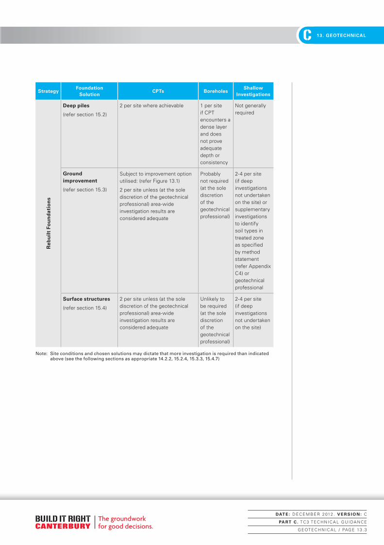
Table 13.1: Summary relationship between likely final investigation densities and
foundation types
StrategyFoundation
SolutionCPTs Boreholes
Shallow Investigations
Rep
aire
d F
ou
nd
atio
ns
No foundation relevel required
(refer Table 2.3 in Part A and Figures 14.1 & 14.2)
Not required Not required Not required
Foundation repair and/or minor (local) relevel required
(refer Table 2.3 in Part A and Figures 14.1 & 14.2)
Not required Not required Not generally required
Foundation relevel required
(refer Table 2.3 in Part A and Figures 14.1 & 14.2)
Type
A & B
Probably not required (at the discretion of the geotechnical professional)
Not required 2 per site
Type C As appropriate to relevel strategy or 1 per site on poor sites unless area-wide investigation adequate
Not required 2 per site
UPDATE:December 2012
DAT E : D E C E M B E R 2 012 . V E R S I O N : C
PA RT C . T C 3 T E C H N I C A L G U I DA N C E
G E OT E C H N I C A L / PAG E 13 . 2
Canterbury Technical Guidance - PART C.indd 2 22/01/2013 11:19:27 a.m.
C 2. FOUNDATION ASSESSMENTC 13. GEOTECHNICAL
StrategyFoundation
SolutionCPTs Boreholes
Shallow Investigations
Reb
uil
t Fo
un
dat
ion
s
Deep piles
(refer section 15.2)
2 per site where achievable 1 per site if CPT encounters a dense layer and does not prove adequate depth or consistency
Not generally required
Ground improvement
(refer section 15.3)
Subject to improvement option utilised: (refer Figure 13.1)
2 per site unless (at the sole discretion of the geotechnical professional) area-wide investigation results are considered adequate
Probably not required (at the sole discretion of the geotechnical professional)
2-4 per site (if deep investigations not undertaken on the site) or supplementary investigations to identify soil types in treated zone as specified by method statement (refer Appendix C4) or geotechnical professional
Surface structures
(refer section 15.4)
2 per site unless (at the sole discretion of the geotechnical professional) area-wide investigation results are considered adequate
Unlikely to be required (at the sole discretion of the geotechnical professional)
2-4 per site (if deep investigations not undertaken on the site)
Note: Site conditions and chosen solutions may dictate that more investigation is required than indicated above (see the following sections as appropriate 14.2.2, 15.2.4, 15.3.3, 15.4.7)
DAT E : D E C E M B E R 2 012 . V E R S I O N : C
PA RT C . T C 3 T E C H N I C A L G U I DA N C E
G E OT E C H N I C A L / PAG E 13 . 3
Canterbury Technical Guidance - PART C.indd 3 22/01/2013 11:19:27 a.m.

C2. FOUNDATION ASSESSMENT C13. GEOTECHNICAL
Figure 13.1: Overview of general geotechnical investigation required
Geotechnical investigation
not necessarily
required
Type A and B
foundation
Surface structures
Ground improvement
Deep piles
Type C foundation
Shallow geotechnical investigation only required
1 deep investigation point (min)
per site (unless
area wide coverage sufficient)
and 2 shallow investigation
points
Investigations as appropriate
to relevel strategy
2 CPT per site (and
borehole as required)
2 deep investigation
points per site unless area-
wide coverage sufficient; shallow
investigation unless deep investigation undertaken
on site
Foundation relevel
required
Refer Figures 4.1,
4.2
Determine foundation relevel/rebuild strategy from Table 2.2 and
2.3 in Part A
Foundation rebuild
required
Local repair and/or minor relevel only
NoNo Yes
Yes
Majority of piles need
replacing (Type A) or
> approx 25-30% foundation beam and/or majority of
piles need replacing (Type B) Site
performed poorly (see Figures 14.1
and 14.2)?
Deep column
solutions
Surface raft
solutions
Note: Site conditions may dictate additional investigations to those indicated above.
DAT E : D E C E M B E R 2 012 . V E R S I O N : C
PA RT C . T C 3 T E C H N I C A L G U I DA N C E
G E OT E C H N I C A L / PAG E 13 . 4
Canterbury Technical Guidance - PART C.indd 4 22/01/2013 11:19:27 a.m.

C 2. FOUNDATION ASSESSMENTC 13. GEOTECHNICAL
13.2 Single or isolated house site investigation
The geotechnical investigation process in TC3 should broadly follow the subdivision investigation requirements set out in Part D, under the guidance of a CPEng. geotechnical engineer or suitably experienced PEngGeol. engineering geologist.
Where practical at least two deep investigation points (CPTs, boreholes with SPTs, etc) should be undertaken to enable site characterisation to 10–15 m depth. This might be achieved in conjunction with nearby existing deeper information where it is feasible on or immediately adjacent to the site.
Given the relative cost of CPT data it is considered best practice to push CPTs to refusal, however where there are very deep deposits (for example in excess of 20 m) of penetrable materials some judgement is required regarding the usefulness of the deeper information. It must be recognised also that early termination of CPT investigation depths may result in loss of potentially useful information regarding possible pile founding depths, ground improvement options, overall site settlements and general site characterisation. Conversely, while a minimum target depth of 15 m is recommended (and early termination at this depth is not encouraged), if CPTs refuse at between 10 m and 15 m depth the cost of a physical borehole to gain additional information may not be warranted in the first instance, in all cases.
It is recognised that CPT data is generally superior to SPT data in determining liquefaction susceptibility, and therefore CPTs will normally be carried out in preference to SPTs. CPT equipment should be calibrated, and procedures carried out, to ASTM D5778-12. Where ground conditions dictate the need for SPTs it is important that equipment that has been properly energy rated is used so that an appropriate energy ratio can be used to correct SPT ‘N’ values.
In many cases only a single location will be initially feasible (due to access considerations and other constraints). In some cases where CPT testing is hampered by gravel layers, a single borehole with SPT testing may be appropriate, augmented by shallower investigations. It will then be up to the judgement of the CPEng. Geotechnical Engineer or PEngGeol. whether these may be supplemented by additional shallow investigations, geophysical testing and/or if further deep investigation points are necessary (either during the initial investigation phase, or possibly post-demolition where this occurs).
Groundwater measurements during the investigations should also be undertaken. Liquefaction assessments should be carried out following the guidelines in section 13.5, as well as further analyses appropriate to the particular foundation or ground remediation solutions being considered for the site.
In addition to the above deep investigations, shallow testing (in accordance with TC2 requirements) can be used to supplement the deep investigations as required.
UPDATE:December 2012
UPDATE:December 2012
UPDATE:December 2012
DAT E : D E C E M B E R 2 012 . V E R S I O N : C
PA RT C . T C 3 T E C H N I C A L G U I DA N C E
G E OT E C H N I C A L / PAG E 13 . 5
Canterbury Technical Guidance - PART C.indd 5 22/01/2013 11:19:27 a.m.

C2. FOUNDATION ASSESSMENT C13. GEOTECHNICAL
13.3 Area-wide investigations
Where a large number of house sites are to be grouped together for an area-wide or suburb-by-suburb investigation, and the area-wide investigation shows ground conditions to be relatively consistent, the number of investigation points may be able to be reduced and still allow analyses of individual house sites based on the information from an area-wide investigation. The use or application of area-wide investigations can be applied by engineers whether they are working on multiple properties for a specific client (such as a PMO Engineer working for EQC or an insurer) or on an individual site for a property owner, where deemed appropriate by the engineer.
Such a reduction of investigation density will have to be at the discretion of the CPEng. geotechnical engineer or suitably trained and experienced PEngGeol. engineering geologist for each specific site. The density will need to be such that geotechnical professionals are comfortable with the likely quality of data and proximity of data points to the house sites they are working on. The density of investigations is expected to be in the order of six to eight investigations per hectare. Further investigation points may be required, depending on the consistency and quality of the data obtained, the type of foundation solution being considered for a particular site, and the underlying soil conditions. These factors may have considerable influence on the final amount of geotechnical investigation carried out. Where deep piles are opted for, more intense site-specific investigations, are likely to be necessary. In addition to the above deep investigations, shallow testing (in accordance with TC2 requirements) can be used to supplement the deep investigations as required.
13.4 Geotechnical investigation requirements for repaired and rebuilt foundations
Different geotechnical investigation requirements apply to dwellings with foundations that can be repaired compared to dwellings with foundations that will be replaced. To determine whether foundation repair or replacement is required, refer to Part A, Table 2.2 and Table 2.3 and Figures 14.1 and 14.2.
In general, foundations that require minor repair or relevelling only will not necessarily require geotechnical investigations. Those foundations with significant damage will require deep investigations so that a liquefaction analysis can be undertaken to determine likely future settlements. The foundation repair or replacement strategy for these dwellings will be determined by the outcomes of the liquefaction analysis.
UPDATE:December 2012
DAT E : D E C E M B E R 2 012 . V E R S I O N : C
PA RT C . T C 3 T E C H N I C A L G U I DA N C E
G E OT E C H N I C A L / PAG E 13 . 6
Canterbury Technical Guidance - PART C.indd 6 22/01/2013 11:19:27 a.m.

C 2. FOUNDATION ASSESSMENTC 13. GEOTECHNICAL
13.5 Liquefaction assessment
In addition to standard geotechnical characterisation, the site data should be analysed using recognised methods as outlined below to determine liquefaction susceptibility, and in particular likely ground deformations under design serviceability limit state (SLS) and ultimate limit state (ULS) ground motions. (It is important to note that the methods outlined below must be employed when using these guidance documents).
13.5.1 Liquefaction analysis methodologies (minimum requirements)A standard liquefaction analysis methodology outlined below, and repeated in Part D, shall be used in conjunction with specified input ground motions and, where appropriate, observations of land damage from recent seismic events. As discussed in section 12, it is recognised that the calculation of liquefaction-induced settlements is an inexact process. For the purposes of calculating consistent ‘index numbers’ to compare with nominal ‘limits’ set out in these guidance documents, a consistent methodology will need to be adopted by all users. These methodologies should only be applied by those with a strong background in geotechnical earthquake engineering. Other methods or adjustments that are not included in this document (for example ‘thin layer’ correction techniques) do not form part of this methodology.
For the purposes of this document, calculations of liquefaction potential (triggering) should be carried out using the methods of Idriss & Boulanger 2008, as outlined in the publication “Soil Liquefaction During Earthquakes” – EERI monograph MNO12. Only data obtained directly from CPT, SPT or seismic shear wave velocity measurements shall be used in carrying out liquefaction assessments. Where primary data has been obtained for the site using these methods, and site access constrains the further use of these primary methods, supplementary infill data can be considered from Swedish Weight Sounding or DPT using recognised correlations. For fines corrections where soil samples have not been retrieved and tested, the method of Robertson and Wride (1998) should be used. For the calculation of post-liquefaction induced settlements, the method of Zhang et al (2002) is to be used. It should be noted that this does not imply that these methodologies are mandated for applications outside the scope of this document.
For comparison against ‘index values’ in these guidelines, calculations can generally be limited to the upper 10 m of the soil profile. (This does not however extend to section 15.3 - Site ground improvement). Potential issues do also need to be considered below 10 m depth (refer to section 13.6 for details).
Ground input motionsGround input motions for SLS and ULS liquefaction analysis are provided in Appendix C2. In summary, for deep soft soil (Class D) sites they are:
• SLS 0.13g
• ULS 0.35g
These figures are the result of extensive probabilistic modelling by GNS Science and observations of land and building damage caused during the Canterbury earthquake sequence, and are recommended by the Ministry as of April 2012 for liquefaction analyses on the flat land of Christchurch.
DELETION:December 2012
UPDATE:December 2012
UPDATE:December 2012
DAT E : D E C E M B E R 2 012 . V E R S I O N : C
PA RT C . T C 3 T E C H N I C A L G U I DA N C E
G E OT E C H N I C A L / PAG E 13 . 7
Canterbury Technical Guidance - PART C.indd 7 22/01/2013 11:19:28 a.m.

C2. FOUNDATION ASSESSMENT C13. GEOTECHNICAL
In response to new knowledge about the seismic risk in the Canterbury earthquake region, the former Department of Building and Housing (now the Ministry) made changes to the Verification Method B1/VM1, from 19 May 2011, to increase the seismic hazard factor Z (as described in AS/NZS 1170) for the region. The update to B1/VM1 states that the revised Z factor is intended only for use for the design and assessment of buildings and structures – it is not applicable for use in geotechnical design. The figures above are now provided to be used for liquefaction analysis.
Liquefaction hazard, liquefaction-induced settlements and lateral spreadFor design guidance refer to the following documents or methodologies (It should be noted that this does not imply that these methodologies are mandated for applications outside the scope of this document):
• For background information: refer to the latest edition of NZGS guidelines “Geotechnical Earthquake Engineering Practice Module 1 – Guideline for the identification, assessment and mitigation of liquefaction hazards” (current edition July 2010).
• For specific analysis methodology for liquefaction triggering: refer to Idriss & Boulanger 2008 “Soil Liquefaction During Earthquakes” – EERI monograph MNO12.
• ‘For estimating apparent fines content (FC) for use in the CPT fines correction, set out in Idriss & Boulanger (2008) (equation 78), where soil samples are not being retrieved: refer to Robertson and Wride (1998) “Evaluating Cyclic Liquefaction Potential Using the Cone Penetration Test” Can. Geotech. J. 35(3), 442-459. ie, – (a) if Ic <1.26, apparent FC = 0%; (b) if 1.26 < Ic< 3.5, apparent FC (%) =1.75 Ic3.25 - 3.7; and (c) if Ic > 3.5, apparent FC =100%.
• For estimation of post-liquefaction induced settlements in CPT analyses, refer to Zhang, Robertson & Brachman (2002) “Estimating Liquefaction-Induced Ground Settlements from CPT for Level Ground”, Can. Geotech. J. (39), 1168-1180. In particular, Appendix A of that paper provides useful guidance on calculating volumetric strains. Note: the input parameters of FOS and (qc1n)cs are to be derived from the method of Idriss & Boulanger (2008), as modified above.
• For surface crust assessment: refer to Ishihara (1985) “Stability of Natural Deposits During Earthquakes” Proc. of the 11th International Conference in Soil Mechanics and Foundation Engineering, pp 321-376 – Figure 88 p 362. (Reproduced as Figure 107 on p 157 of Idriss & Boulanger (2008) (optional).
UPDATE:December 2012
DAT E : D E C E M B E R 2 012 . V E R S I O N : C
PA RT C . T C 3 T E C H N I C A L G U I DA N C E
G E OT E C H N I C A L / PAG E 13 . 8
Canterbury Technical Guidance - PART C.indd 8 22/01/2013 11:19:28 a.m.

C 2. FOUNDATION ASSESSMENTC 13. GEOTECHNICAL
• For refinement of SLS assessment: observations of damage or lack thereof in areas deemed to have been “sufficiently tested at SLS” by recent seismic events can be used to judge the applicability, or not, of settlements calculated at the design SLS level (optional). This can be achieved with reference to the PGA conditional median contours and associated conditional standard deviations contained in the paper (Bradley and Hughes 2012) and kmz file that can be found at the Canterbury Geotechnical Database https://canterburygeotechnicaldatabase.projectorbit.com.
− As an initial screening tool, where a site has experienced at least 170% of design SLS (using the conditional median pga values from one of the three compiled events corrected to a M7.5 event; ie PGA7.5 = PGA/MSF), then the site can be regarded as having been ‘sufficiently tested’ for an SLS event.
− If this screening test is not met, then the site can be evaluated by calculating the 10 percentile PGA from each of the three compiled events (i.e. the median value less 1.28 standard deviations, again magnitude scaled to M7.5). If one of these values equals or exceeds the design SLS event then the site can be regarded as having been ‘sufficiently tested’ for an SLS event. (At this level it is likely that most sites will have been tested to SLS or beyond by enough of a margin that in future SLS events the land damage will likely be no worse than already experienced at that site).
− To calculate the 10 percentile PGA, use PGA10 = PGA50*exp(-1.28*σlnPGA), where PGA50 is the conditional median PGA and σlnPGA is the conditional standard deviation of PGA at a site. For consistency with the methodology used to analyse liquefaction triggering, the Magnitude Scaling Factor of Idriss & Boulanger (2008) should be used – i.e. MSF = [6.9*exp(-M/4)]-0.058 ≤1.8. Thus, PGA10_7.5 = PGA10/MSF.
Note: This does not imply that these methodologies are mandated for applications outside the scope of this document.
It is hoped that, with time, a modified methodology for liquefaction settlement/damage calculation that is depth-weighted will be derived from extensive site data and damage observations in the recent earthquake sequence. This may be incorporated in these requirements at an appropriate stage.
Modification by reference to soil deposit ageing is not considered appropriate in the Canterbury region.
Guidance on determining nominal lateral spread zonings is given in section 12.2 of this document.
DAT E : D E C E M B E R 2 012 . V E R S I O N : C
PA RT C . T C 3 T E C H N I C A L G U I DA N C E
G E OT E C H N I C A L / PAG E 13 . 9
Canterbury Technical Guidance - PART C.indd 9 22/01/2013 11:19:28 a.m.

C2. FOUNDATION ASSESSMENT C13. GEOTECHNICAL
13.6 Technical Category TC3 confirmation
If damage to the land or foundations is less than implied by the TC3 categorisation, then the deep geotechnical investigation and liquefaction analysis undertaken by a CPEng. geotechnical engineer or suitably qualified PEngGeol. engineering geologist may indicate that the site has TC2 rather than TC3 performance characteristics for that particular site. As part of this determination, liquefaction characteristics need to be assessed over the full depth of the soil profile investigated. However, when comparing calculated settlement values to the index values in Table 3.1 in Part A, calculations can be limited to the upper 10 m of the soil profile. This does not in any way imply that potential issues do not need to be considered below 10 m depth, this is simply a calculated ‘index’ number for comparison to the index values in Table 3.1 in Part A. Full depth settlement assessments should also be carried out, to allow consideration of (for example) differential settlements where deep liquefiable deposits vary significantly across a site. For this reason, CPTs should not be termiated short of refusal depth. Specific design based on the deep geotechnical investigation and TC2 solutions signed off by a suitably qualified CPEng. geotechnical engineer can then be undertaken.
As part of the building consent process, or in some cases independent from that process, the geotechnical information and the geotechnical report will be submitted to the Canterbury Geotechnical Database. The geotechnical report will contain the results of the liquefaction analyses and a reasoned justification from the CPEng. geotechnical engineer or suitably qualified and experienced PEngGeol. engineering geologist to support the opinion of TC2 – like site performance.
This will allow the use of TC2 foundation systems on those individual sites where such suitability has been determined by the CPEng. geotechnical engineer or suitably qualified and experienced PEngGeol. engineering geologist.
The emphasis is on carrying out investigations to allow the design of a suitable foundation system for the site, whether that is a TC3 compliant system or a TC2 compliant system.
13.7 Longevity of factual and interpretative reports
It is considered in most cases that factual geotechnical investigation information (eg, CPT data, borehole data etc) would be appropriate for engineering use for at least five years and in many cases longer (at the discretion of the geotechnical engineer).
The predominant geotechnical issue that most properties in TC3 areas will be facing are liquefaction-related or bearing capacity issues. Some sites will also have compressible peat soils to consider. With regard to liquefaction, the underlying soils generally return to their pre-earthquake densities soon after seismic events.
UPDATE:December 2012
DELETION:December 2012
DAT E : D E C E M B E R 2 012 . V E R S I O N : C
PA RT C . T C 3 T E C H N I C A L G U I DA N C E
G E OT E C H N I C A L / PAG E 13 . 10
Canterbury Technical Guidance - PART C.indd 10 22/01/2013 11:19:28 a.m.

C 2. FOUNDATION ASSESSMENTC 13. GEOTECHNICAL
The most likely change that might occur over time is a change in the groundwater profile. Engineers should consider this in their judgements and, if appropriate, undertake updated groundwater level investigations if historic information is being used. It is noted that interpretive methodologies are changing with time, and site usage can also vary. It is recommended that if an interpretive report is more than two years old, or the proposed building that the report originally applied to has changed significantly, (eg, layout, height, weight of building materials, foundation loads etc) and/or design loadings have changed (eg, design PGA levels), then the report is reviewed by the geotechnical engineer for current applicability.
Additionally, if the site has been altered by excavations or filling, the report will need to be reviewed.
13.8 Building consent information
For information on the Canterbury Geotechnical Database and the format for building consents, refer to sections 8.2.5 and 8.2.6.
UPDATE:December 2012
DAT E : D E C E M B E R 2 012 . V E R S I O N : C
PA RT C . T C 3 T E C H N I C A L G U I DA N C E
G E OT E C H N I C A L / PAG E 13 . 11
Canterbury Technical Guidance - PART C.indd 11 22/01/2013 11:19:28 a.m.

C2. FOUNDATION ASSESSMENT C13. GEOTECHNICAL
DAT E : D E C E M B E R 2 012 . V E R S I O N : C
PA RT C . T C 3 T E C H N I C A L G U I DA N C E
G E OT E C H N I C A L / PAG E 13 . 12
Canterbury Technical Guidance - PART C.indd 12 22/01/2013 11:19:28 a.m.

C 2. FOUNDATION ASSESSMENTC 14. REPAIRING
FOUNDATIONS
14 Repairing house foundations in TC3
14.1 General
This section contains suggested approaches for the repair and reinstatement of house foundations where the level of damage does not require foundation replacement or complete rebuilding. It is emphasised that these approaches will not suit all houses that are considered repairable, and that each house will require careful consideration.
Situations involving the complete replacement of the foundations beneath an existing house, or the construction of a new dwelling, are addressed in section 15.
In general, the provisions in this section apply only to those sites in the ‘Moderate’ lateral stretch category (see section 12.2).
14.2 Assessment of foundation damage
The first step in assessing repair options for a damaged house in TC3 is to make a reasoned judgement on the severity of the damage that has occurred to the house structure.
Tables 2.2 and 2.3 in Part A give guidance on whether foundation damage requiring specific engineering input is present. As indicated in Part A, sections 2.2 and 2.3, sound engineering judgement must be applied when using these tables.
For example, criteria that need to be considered in a domestic house include:
• the intended use of the space
• construction materials of the floor surfacing
• practicality of the repair (ie, cost versus benefits)
• capacity to resist deformation
• effect of gradients on amenity of the space.
These considerations may trigger the need for relevelling or rebuilding in some situations where the guideline tables do not indicate such a situation, and conversely it is also expected that in other situations, despite being indicated by the guideline table, relevelling or rebuilding is not necessarily warranted.
In applying the indicator criteria from Table 2.2 in Part A, due consideration must be given to the amount of damage that was likely to have been present before the earthquake events, and some guidance on this is given in Part A, section 2.2.
If more than just cosmetic repairs are necessary, then the indicator criteria in Table 2.3 in Part A should be used in conjunction with engineering judgement to determine the level of repairs necessary for the structure. This decision will be based on the criteria in Table 2.2 in Part A and sound engineering judgement. Again, reference must be made to Part A, section 2.3 when using these indicator criteria.
DELETION:December 2012
DAT E : D E C E M B E R 2 012 . V E R S I O N : C
PA RT C . T C 3 T E C H N I C A L G U I DA N C E
R E PA I R I N G F OU N DAT I O N S / PAG E 14 . 1
Canterbury Technical Guidance - PART C.indd 1 22/01/2013 11:19:28 a.m.

C2. FOUNDATION ASSESSMENT C14. REPAIRING FOUNDATIONS
If no foundation damage is present that requires repair and specific engineering design, then superstructure repairs can proceed using guidance from Part A, section 7. In this case, minor cracks (<5 mm) in concrete floors and foundation beams can be repaired in accordance with Appendix A4 of those guidelines. No geotechnical investigation will be required in these cases.
Generally a decision will be made on whether a structure corresponds to one of the following cases:
• Case 1: Local repair and/or minor (local) relevel only required
• Case 2: Foundation relevel required (ie, widespread differential settlements)
• Case 3: Foundation rebuild required
• Case 4: Total demolition and rebuild required (ie, new structure)
For Case 4, if the house is to be demolished and a new structure built, the foundation solutions in section 15 of this document should be referred to. The extent of investigations will vary, and are described in sections 13 and 15.
For Cases 1 to 4 above, where varying degrees of foundation repair and/or relevelling is required, reference should be made to the process flow charts in Figure 14.1 (foundation Types A and B) and Figure 14.2 (foundation Type C) to determine both investigation requirements and actions to be taken.
UPDATE:December 2012
DAT E : D E C E M B E R 2 012 . V E R S I O N : C
PA RT C . T C 3 T E C H N I C A L G U I DA N C E
R E PA I R I N G F OU N DAT I O N S / PAG E 14 . 2
Canterbury Technical Guidance - PART C.indd 2 22/01/2013 11:19:29 a.m.

C 2. FOUNDATION ASSESSMENTC 14. REPAIRING
FOUNDATIONS
Figure 14.1: Overview of process for repairing foundations on TC3 sites for Foundation
Types A and B
*Note
: If t
here
is a
st
rong
pre
fere
nce
or
reas
on to
oth
erw
ise
reta
in h
eavy
cla
ddin
gs o
r ro
ofing
mat
eria
ls, t
hen
foun
datio
ns w
ill n
eed
to
be u
pgra
ded
to c
ope
with
th
is, b
y pi
le u
nder
pinn
ing,
gr
ound
impr
ovem
ent,
fo
unda
tion
repl
acem
ent o
r th
e lik
e –
this
will
requ
ire
an a
ppro
pria
te le
vel o
f ge
otec
hnic
al in
vest
igat
ion
to a
lso
be c
arrie
d ou
t.
Follo
w g
uida
nce
in P
art
A
Rem
ove
heav
y ro
of a
nd c
ladd
ing
and
repl
ace
with
ligh
t-w
eigh
t*R
emov
e he
avy
roof
and
re
plac
e w
ith li
ght-
wei
ght*
Rem
ove
heav
y ro
of a
nd r
epla
ce w
ith
light
-wei
ght;
rem
ove
heav
y cl
addi
ng
(opt
iona
l if
clad
ding
und
amag
ed) a
nd
repl
ace
with
non
-rig
id li
ght-
wei
ght*
(Typ
e A) Rep
lace
pile
s as
nec
essa
ry O
R (Ty
pe
B) Rep
lace
pile
s as
nec
essa
ry A
ND R
eplace
up to 3
0% o
f foundation b
eam w
ith
TC2
stiffened
bea
m (re
fer to P
art A F
ig 4
.2 O
R R
eplace
par
t or
all of foundation b
eam w
ith c
oncrete
mas
onar
y wall (Fig 1
4.3)
Rem
ove
heav
y ro
of a
nd w
all e
lem
ents
an
d re
plac
e w
ith li
ght-
wei
ght*
AND
R
efer
sec
tion
5 fo
r fo
unda
tion
rebu
ild
optio
ns
Rep
air
foun
datio
n A
ND
rel
evel
as
nece
ssar
y (r
efer
to
Par
t A
)
Site
pe
rfor
med
po
orly
, or
appr
ecia
ble
over
all b
uild
ing
sett
lem
ent
rela
tive
to t
he
grou
nd?
Site
m
eets
the
re
quire
men
ts o
f TC
2?
No
Yes
(may
req
uire
de
ep g
eote
chni
cal
inve
stig
atio
n)
Con
side
r re
mov
ing
heav
y co
mpo
nent
s an
d re
plac
ing
with
lig
ht-w
eigh
t
No
Yes
No
Maj
orit
y of
pile
s ne
ed
repl
acin
g (T
ype
A) O
R
> a
ppro
xim
atel
y 25
–30%
fo
unda
tion
beam
and
/or
maj
orit
y of
pile
s n
eed
rep
laci
ng
(Typ
e B
)Ye
s
No
Yes
App
reci
able
ov
eral
l bui
ldin
g se
ttle
men
t re
lativ
e
to t
he g
roun
d?
No
Site
per
form
ed
poor
ly?
(eg,
larg
e am
ount
s of
eje
cta/
exte
nsiv
e gr
ound
cra
ckin
g/gr
ound
un
dula
tions
etc
)
Cas
e 1:
Loca
l rep
air
and/
or m
inor
rel
evel
onl
y re
quire
d
Cas
e 2:
Foun
datio
n re
leve
l ind
icat
ed b
y Ta
ble
2.3
in P
art
A
Cas
es 3
and 4
:
Foun
datio
n re
build
indi
cate
d
by T
able
2.3
in P
art
A
No
SLS
se
ttle
men
ts <
10
0 m
m in
upp
er 1
0 m
of
soil
profi
le
Dee
p ge
otec
hnic
al
inve
stig
atio
n in
form
atio
n
Yes
Sha
llow
(TC
2 ty
pe)
tech
nica
l inv
estig
atio
n
Typ
e A
or
B
DAT E : D E C E M B E R 2 012 . V E R S I O N : C
PA RT C . T C 3 T E C H N I C A L G U I DA N C E
R E PA I R I N G F OU N DAT I O N S / PAG E 14 . 3
Canterbury Technical Guidance - PART C.indd 3 22/01/2013 11:19:29 a.m.
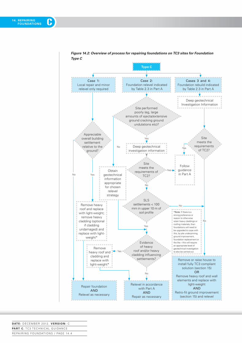
C2. FOUNDATION ASSESSMENT C14. REPAIRING FOUNDATIONS
Figure 14.2: Overview of process for repairing foundations on TC3 sites for Foundation
Type C
Relevel in accordance with Part A
AND Repair as necessary
Repair foundation AND
Relevel as necessary
Remove or raise house to install fully TC3 compliant
solution (section 15) OR
Remove heavy roof and wall elements and replace with
light-weight AND
Retro-fit ground improvement (section 15) and relevel
SLS settlements < 100
mm in upper 10 m of soil profile
Yes
Follow guidance in Part A
Deep geotechnical investigation information
Yes
Yes
No
Yes
Evidence of heavy
roof and/or heavy cladding influencing
settlements?
No
No
No
No
Yes
Obtain geotechnical information appropriate for chosen
relevel strategy
No
Site meets the
requirements of TC2?
Yes
Type C
Cases 3 and 4: Foundation rebuild indicated
by Table 2.3 in Part A
Deep geotechnical Investigation Information
Case 2: Foundation relevel indicated
by Table 2.3 in Part A
Appreciable overall building
settlement relative to the
ground?
Remove heavy roof and replace
with light-weight; remove heavy
cladding (optional if cladding
undamaged) and replace with light-
weight*
Remove heavy roof and cladding and replace with light-weight*
Site meets the
requirements of TC2?
Site performed poorly (eg, large
amounts of ejecta/extensive ground cracking ground
undulations etc)?
Case 1: Local repair and minor relevel only required
*Note: If there is a strong preference or reason to otherwise retain heavy claddings or roofing materials, then foundations will need to be upgraded to cope with this, by pile underpinning, ground improvement, foundation replacement or the like – this will require an appropriate level of geotechnical investigation to also be carried out.
DAT E : D E C E M B E R 2 012 . V E R S I O N : C
PA RT C . T C 3 T E C H N I C A L G U I DA N C E
R E PA I R I N G F OU N DAT I O N S / PAG E 14 . 4
Canterbury Technical Guidance - PART C.indd 4 22/01/2013 11:19:29 a.m.
C 2. FOUNDATION ASSESSMENTC 14. REPAIRING
FOUNDATIONS
14.2.1 Case 1 – local repair (and local relevel)If a house has sustained only minor foundation damage (ie, substantial relevelling is not required), but local repairs are necessary, then a deep geotechnical investigation is not necessarily required. An assessment of whether the site and building have performed well or not should be made. In order to make a fully reasoned assessment on the extent or repairs or modifications necessary, engineering judgement will be required. Factors to consider include:
• Were there large amounts of liquefaction ejecta during the earthquake events?
• Was there extensive ground cracking of the site?
• Are there large ground undulations as a result of the earthquake events?
• Has the dwelling settled relative to the surrounding land?
If the site and building have performed well (and in the case of a Type A or B house with a heavy roof, there are no indications of significant damage to the ceiling or wall linings of the house), then localised foundation repairs and minor (local) relevelling can proceed. This might include replacement of short sections of a Type B foundation beam with an enhanced perimeter beam (refer Figure 4.2 and Figure 4.2a in Part A).
Load reduction strategiesThe following load reduction strategies are recommended for heavily clad houses:
For a Type A or B house with a heavy roof, where there are signs of significant damage to the linings, indicating that the heavy roof has caused enhanced levels of damage, it is recommended that consideration be given to removal of the heavy roof and replacement with light-weight roofing materials (ie, corrugated steel, pressed steel tiles etc).
For Type A or B houses with heavy roofs and/or heavy claddings where:
a) the site has not performed well, or
b) there is evidence that the building has settled (albeit evenly) relative to the ground (this applies to all foundation types)
It is strongly recommended that the heavy roof is removed and replaced with light-weight materials. Scenario b) above indicates that the weight of the building is giving rise to undesired or adverse performance.
For Type C homes with heavy roofs and/or heavy claddings where there has been appreciable building settlement relative to the ground, the roof should be removed and replaced with light-weight. Where heavy claddings are damaged, the cladding should be removed and replaced with light-weight.
Where a heavy cladding has been damaged to the extent that it requires removal then it is recommended that the cladding be replaced with light-weight (or medium-weight) materials. If claddings are to be altered or replaced, an appropriate level of professional advice should be sought to ensure the new claddings are suitable for the existing building.
UPDATE:December 2012
UPDATE:December 2012
DAT E : D E C E M B E R 2 012 . V E R S I O N : C
PA RT C . T C 3 T E C H N I C A L G U I DA N C E
R E PA I R I N G F OU N DAT I O N S / PAG E 14 . 5
Canterbury Technical Guidance - PART C.indd 5 22/01/2013 11:19:29 a.m.

C2. FOUNDATION ASSESSMENT C14. REPAIRING FOUNDATIONS
Where foundation damage has occurred and there is a strong preference or reason to retain heavy claddings or roofing materials, then the foundations will need to be upgraded if poor house and/or ground performance is observed. Possible methods may include pile underpinning, ground improvement, foundation replacement or the like. This will require an appropriate level of geotechnical investigation to be carried out.
In all cases it is recommended that abandoned chimney bases or concrete foundations that are no longer required are removed. These structures have been observed to cause local differential settlement during liquefaction events. If a chimney is to remain then it is strongly recommended that any framing elements, subfloor elements and their supports are decoupled from the chimney base.
14.2.2 Case 2 – foundation relevel (and local repair)If foundation relevelling is required and considered achievable, then the following factors need to be taken into account:
• the nature and extent of damage
• the lateral spreading (stretch) potential
• the liquefaction-induced vertical settlement potential
• whether the dwelling has settled relative to the surrounding land.
Repairs and relevelling can be considered if a site is assessed as having moderate (refer Table 12.1) lateral stretch potential (ie, <200 mm at ULS) (refer to the three lateral stretch categories outlined in 12.2).
If a site is assessed as having major or severe lateral stretch potential (ie, >200 mm at ULS), then neither repairs nor relevelling should be undertaken without careful engineering analysis and consideration.
In areas identified as having major global lateral movement potential, care will need to be taken with repairs to houses that are supported on deep piles.
Type A and B foundations can be relevelled if damage to the foundations is not too severe. The threshold of damage below which full foundation replacement is not required is:
• for Type A – majority of piles not needing replacement
• for Type B – less than approximately 25-30% of the foundation beam needing replacement and/or the majority of piles not needing replacement. (See the middle pathway of the flowchart in Figure 14.1).
UPDATE:December 2012
DAT E : D E C E M B E R 2 012 . V E R S I O N : C
PA RT C . T C 3 T E C H N I C A L G U I DA N C E
R E PA I R I N G F OU N DAT I O N S / PAG E 14 . 6
Canterbury Technical Guidance - PART C.indd 6 22/01/2013 11:19:29 a.m.

C 2. FOUNDATION ASSESSMENTC 14. REPAIRING
FOUNDATIONS
If these damage levels are exceeded for Type A and B houses, then it becomes a foundation rebuild situation (ie, Case 3). If not, then relevelling and local repairs can proceed in accordance with Part A, section 4.3, following a shallow investigation to determine the shallow bearing capacity. With reference to Figures 4.1 and 4.3 in Part A , if the static geotechnical ULS bearing capacity is confirmed as being greater than 300 kPa, then the construction and engineering sign-off on a building consent application can be in accordance with NZS 3604 and this section. If the static geotechnical ULS bearing capacity is less than 300 kPa, then the engineering sign-off on a building consent application will be based on specific engineering design and this section may be used to support the building consent application. See Part A, section 3.4.1 for further guidance on specific engineering design calculations of bearing pressures.
If relevelling is carried out using permanent deep piles then at least all perimeter foundation elements and load bearing walls should be supported on such piles (to prevent future gross differential movements). Internal non-loadbearing timber floors may require future relevelling or packing if supported on shallow piles in this case. The use of differential support systems is not recommended where significant peat deposits are present.
In addition, the performance of the site needs to be assessed. If the performance has been poor (eg, significant surface ejecta, extensive ground cracking, ground undulations etc), then it is strongly recommended that any heavy roofing materials and any heavy cladding materials are removed and replaced with light-weight materials before relevelling. If the site and building have performed relatively well, then the recommendation applies only to heavy roofing materials.
Where foundation damage has occurred and there is a strong preference or reason to retain heavy claddings or roofing materials, then the foundations will need to be upgraded. Possible methods include - pile underpinning, ground improvement, foundation replacement or the like. This will require an appropriate level of geotechnical investigation to be carried out.
The perimeter wall of a Type B dwelling with less than 25% to 30% damage can be fully replaced with an alternate concrete masonry wall as shown in Figure 14.3 where the resulting cladding is light or medium-weight and roof is light-weight.
UPDATE:December 2012
DAT E : D E C E M B E R 2 012 . V E R S I O N : C
PA RT C . T C 3 T E C H N I C A L G U I DA N C E
R E PA I R I N G F OU N DAT I O N S / PAG E 14 . 7
Canterbury Technical Guidance - PART C.indd 7 22/01/2013 11:19:29 a.m.
C2. FOUNDATION ASSESSMENT C14. REPAIRING FOUNDATIONS
Figure 14.3: Perimeter foundation wall detail for TC3
Mid-height subfloor vents should be provided in accordance with NZS 3604. The R10 ties can be in pairs either side of the vents
In all cases it is recommended that abandoned chimney bases or concrete foundations that are no longer required are removed because these structures have been observed to cause local differential settlement during liquefaction events. If a chimney is to remain, then it is strongly recommended that any framing elements, subfloor elements and their supports are decoupled from the chimney base.
For Type C foundations (ie, concrete floor slabs with edge beams) the process is slightly more complicated. Type C foundations typically cannot sustain the same levels of deformation as Types A and B foundations without exhibiting damage. In this case, if the site appears to have performed poorly (eg significant surface ejecta, extensive ground cracking, ground undulations, settlement of the house relative to surrounding land, etc) the results of a deep geotechnical investigation are required in order to gauge the likely future performance of the site, particularly under SLS loadings. As discussed in section 12.3, the SLS settlements over the top 10 metres of the soil profile should be assessed. If this calculated value is more than 100 mm, then it becomes a foundation rebuild situation (ie, case 3). If not, then relevelling and local repairs can proceed in accordance with Part A, section 4.3. The building performance also needs to be assessed in terms of the influence of heavy roofing or cladding materials on settlements. If the performance has been poor (eg, hogging of the floor slab is evident), then it is strongly recommended that any heavy roofing materials and any heavy cladding materials are removed and replaced with light-weight materials before relevelling.
UPDATE:December 2012
DAT E : D E C E M B E R 2 012 . V E R S I O N : C
PA RT C . T C 3 T E C H N I C A L G U I DA N C E
R E PA I R I N G F OU N DAT I O N S / PAG E 14 . 8
Canterbury Technical Guidance - PART C.indd 8 22/01/2013 11:19:29 a.m.
C 2. FOUNDATION ASSESSMENTC 14. REPAIRING
FOUNDATIONS
If the site has performed relatively well, but hogging is still evident, then this recommendation applies only to heavy roofing materials. If there is a strong preference or reason to retain heavy claddings or roofing materials contrary to these recommendations, then the foundations will need to be upgraded to cope with this. Possible methods include pile underpinning, ground improvement, foundation replacement or the like. This will require an appropriate level of geotechnical investigation to be carried out.
If both the site and building have performed well then relevelling can proceed without necessarily removing heavy materials. It is recommended that the removal of heavy materials is still considered in all cases.
14.2.3 Case 3 – foundation rebuildIf a foundation rebuild is required, in most cases the results of a deep geotechnical investigation will be required in accordance with section 13 requirements, and a rebuild will be determined in accordance with section 15.
For Type A and B houses in this situation, if the deep geotechnical investigation demonstrates that the assessed SLS settlements over the top 10 metres of the soil profile is less than 100 mm, then it is permissible to treat the situation as a relevel (ie, it can revert to case 2) if judged appropriate by the engineer. This could include use of the concrete masonry perimeter detail as shown in Figure 14.3.
For a foundation rebuild all heavy roof and cladding elements should be replaced with light-weight materials.
Any of these options may, but not necessarily, require the temporary removal or lifting of the house structure to allow construction to proceed.
For Type C houses, either the house will need to be removed temporarily or raised to allow the construction of one of the foundation options in section 15. It may be possible, in some cases, to install ground improvement with the house in place (eg, LMG piles or jet grouted columns) - in which case all heavy roofing elements and heavy wall claddings will need to be replaced with light-weight materials.
DAT E : D E C E M B E R 2 012 . V E R S I O N : C
PA RT C . T C 3 T E C H N I C A L G U I DA N C E
R E PA I R I N G F OU N DAT I O N S / PAG E 14 . 9
Canterbury Technical Guidance - PART C.indd 9 22/01/2013 11:19:29 a.m.

C2. FOUNDATION ASSESSMENT C14. REPAIRING FOUNDATIONS
DAT E : D E C E M B E R 2 012 . V E R S I O N : C
PA RT C . T C 3 T E C H N I C A L G U I DA N C E
R E PA I R I N G F OU N DAT I O N S / PAG E 14 . 10
Canterbury Technical Guidance - PART C.indd 10 22/01/2013 11:19:30 a.m.
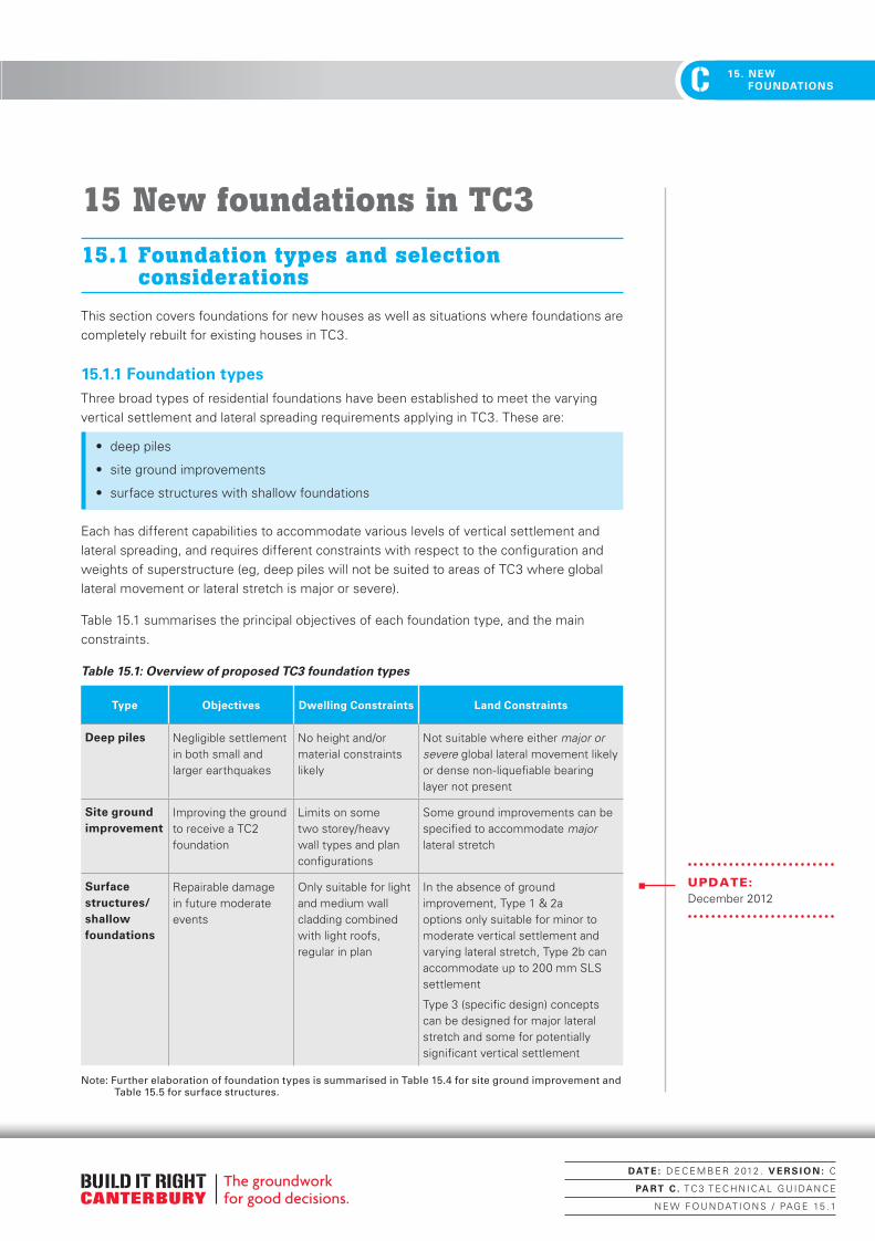
C 2. FOUNDATION ASSESSMENTC 15. NEW
FOUNDATIONS
15 New foundations in TC3
15.1 Foundation types and selection considerations
This section covers foundations for new houses as well as situations where foundations are completely rebuilt for existing houses in TC3.
15.1.1 Foundation typesThree broad types of residential foundations have been established to meet the varying vertical settlement and lateral spreading requirements applying in TC3. These are:
• deep piles
• site ground improvements
• surface structures with shallow foundations
Each has different capabilities to accommodate various levels of vertical settlement and lateral spreading, and requires different constraints with respect to the configuration and weights of superstructure (eg, deep piles will not be suited to areas of TC3 where global lateral movement or lateral stretch is major or severe).
Table 15.1 summarises the principal objectives of each foundation type, and the main constraints.
Table 15.1: Overview of proposed TC3 foundation types
Type Objectives Dwelling Constraints Land Constraints
Deep piles Negligible settlement in both small and larger earthquakes
No height and/or material constraints likely
Not suitable where either major or severe global lateral movement likely or dense non-liquefiable bearing layer not present
Site ground improvement
Improving the ground to receive a TC2 foundation
Limits on some two storey/heavy wall types and plan configurations
Some ground improvements can be specified to accommodate major lateral stretch
Surface structures/ shallow foundations
Repairable damage in future moderate events
Only suitable for light and medium wall cladding combined with light roofs, regular in plan
In the absence of ground improvement, Type 1 & 2a options only suitable for minor to moderate vertical settlement and varying lateral stretch, Type 2b can accommodate up to 200 mm SLS settlement
Type 3 (specific design) concepts can be designed for major lateral stretch and some for potentially significant vertical settlement
Note: Further elaboration of foundation types is summarised in Table 15.4 for site ground improvement and Table 15.5 for surface structures.
UPDATE:December 2012
DAT E : D E C E M B E R 2 012 . V E R S I O N : C
PA RT C . T C 3 T E C H N I C A L G U I DA N C E
N E W F OU N DAT I O N S / PAG E 15 . 1
Canterbury Technical Guidance - PART C.indd 1 22/01/2013 11:19:30 a.m.

C2. FOUNDATION ASSESSMENT C15. NEW FOUNDATIONS
The subsequent sections 15.2 to 15.4 describe each of the foundation types and the options within them in more detail. Specific design parameters, specification and construction guidance are provided as appropriate.
Suitably experienced professional engineers may wish to use other foundation types or systems in TC3.
Guidance is given in each subsection on how the options relate to the categorisation for lateral movement and vertical settlement defined in sections 12.2 and 12.3 respectively.
Table 15.2 summarises the relationship between the commonly used floor and foundation types, and the lateral movement and vertical settlement categories, and compares them with the corresponding options and requirements for TC1 and TC2.
In reading this table it must be remembered that the overall process of selecting and documenting foundation systems and details for houses in TC3 is a specific engineering design process that requires Chartered Professional Engineering input. Depending on the assessed ground conditions and options selected by the Chartered Professional Engineer, some elements can be adopted and specified directly from these Guidelines without further engineering design. These include Types 1 and 2 Site Ground Improvement methods (section 15.3) and the Type 1 and 2 Surface Structures (section 15.4).
Table 15.2: Overview of floor and foundation types for new and rebuilt foundations
(a) Deep piles
TC1 TC2 TC3
Global Lateral Movement (ULS)
Nil Minor <100 mm
Minor to Moderate < 300 mm
Major 300 to 500 mm
Lateral stretch (ULS)
Nil Minor <100 mm
Minor to Moderate < 200 mm
Major 200 to 500 mm
Concrete Slab on Deep Piles
Deep pile options
(section 15.2)
Deep pile options
(section 15.2)
Deep pile options from section 15.2
Not suitable
Note: The use of deep piles in any location or Technical Category requires specific engineering design
UPDATE:December 2012
DAT E : D E C E M B E R 2 012 . V E R S I O N : C
PA RT C . T C 3 T E C H N I C A L G U I DA N C E
N E W F OU N DAT I O N S / PAG E 15 . 2
Canterbury Technical Guidance - PART C.indd 2 22/01/2013 11:19:30 a.m.
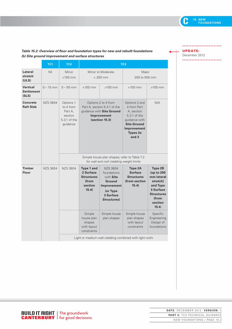
C 2. FOUNDATION ASSESSMENTC 15. NEW
FOUNDATIONS
Table 15.2: Overview of floor and foundation types for new and rebuilt foundations
(b) Site ground improvement and surface structures
TC1 TC2 TC3
Lateral stretch (ULS)
Nil Minor
<100 mm
Minor to Moderate
< 200 mm
Major
200 to 500 mm
Vertical Settlement (SLS)
0 – 15 mm 0 – 50 mm <100 mm >100 mm <100 mm >100 mm
Concrete Raft Slab
NZS 3604 Options 1 to 4 from Part A, section
5.3.1 of the guidance
Options 2 to 4 from Part A, section 5.3.1 of the guidance with Site Ground
Improvement (section 15.3)
Options 2 and 4 from Part A, section
5.3.1 of the guidance with Site Ground
Improvement Types 2a
and 3
N/A
Simple house plan shapes; refer to Table 7.2 for wall and roof cladding weight limits
Timber Floor
NZS 3604 NZS 3604 Type 1 and 2 Surface
Structures (from
section 15.4)
NZS 3604 foundations with Site Ground
Improvement
(or Type 3 Surface
Structures)
Type 2A Surface
Structures (from section
15.4)
Type 2B (up to 200 mm lateral
stretch) and Type 3 Surface
Structures (from
section 15.4)
Simple house plan
shapes with layout constraints
Simple house plan shapes
Simple house plan shapes with layout constraints
Specific Engineering Design of
foundations
Light or medium wall cladding combined with light roofs
UPDATE:December 2012
DAT E : D E C E M B E R 2 012 . V E R S I O N : C
PA RT C . T C 3 T E C H N I C A L G U I DA N C E
N E W F OU N DAT I O N S / PAG E 15 . 3
Canterbury Technical Guidance - PART C.indd 3 22/01/2013 11:19:30 a.m.

C2. FOUNDATION ASSESSMENT C15. NEW FOUNDATIONS
15.1.3 Other considerations in selecting foundations types and finished floor levels for TC3
In addition to the general constraints indicated in Table 15.1 and covered in more detail in subsequent sections, there are other considerations that need to be taken into account in selecting new and rebuilt foundations for TC3.
Building platform heightsThe potential for future liquefaction-induced settlement in many properties in TC3 leads to the geotechnical requirement to limit the increase in mass added to the land. The recommended increase in height for building platforms is 250 mm. Greater increases may be allowable on a site-by-site basis subject to geotechnical engineering assessment.
Flood riskGeneral comments on the flood risk and relationship with floor levels in Christchurch City, Waimakariri District and Selwyn District are provided in Part B, section 8.4.
The current situation with regards to flood risk must be checked on a case-by-case basis with the relevant council.
Insurance contract provisionsSelection of house types and configurations and hence foundation types may be guided by the provisions of insurance contracts as well as regulatory compliance requirements.
For example, some contracts may require that the existing house configuration and materials be incorporated in the rebuilt structure. This would impact on the foundation and superstructure selection process.
The general flowchart in Figure 15.1 provides an illustration of the overall process for the case of a new or rebuilt foundation in TC3 in areas of minor or moderate lateral movement. The flowchart indicates in broad terms the stages at which the above issues that extend beyond geotechnical and structural engineering should be taken into account.
DELETION:December 2012
DAT E : D E C E M B E R 2 012 . V E R S I O N : C
PA RT C . T C 3 T E C H N I C A L G U I DA N C E
N E W F OU N DAT I O N S / PAG E 15 . 4
Canterbury Technical Guidance - PART C.indd 4 22/01/2013 11:19:30 a.m.

C 2. FOUNDATION ASSESSMENTC 15. NEW
FOUNDATIONS
Figure 15.1: General process flowchart for new and rebuilt foundations in TC3 (for sites
with Minor to Moderate lateral ground movement)
TC3 Foundation rebuild Minor/Moderate Lateral
Ground Movement
Assess SLS vertical settlement
potential
>100 mm <100 mm
Dependable founding
layer from deep geotechnical information?
If timber floor selected or required for flood
reasons, check owner acceptance
Adjust foundation solution if required
Specify surface structure Type 1 or 2 or specific design of
Type 3
Specify ground improvement
measures and slab or timber floor over
Design and specification of piles
and slab over
Engineering sign-off and BCA review
Engineering sign-off and BCA review
Engineering sign-off and BCA review
No
Yes
Other considerations including insurance contract provisions
Establish finished floor levelCheck against relevant flood criteria (2% AEP or Plan Change 48 as applicable)
Select ground improvement option and concrete slab
option or timber floor over
Surface structures Ground
improvement
Confirm site suitability
• includingshallowgeotechnical investigation
Confirm site suitability
• includingshallowgeotechnical investigation
Deep piles
UPDATE:December 2012
(See Table 15.2)
DAT E : D E C E M B E R 2 012 . V E R S I O N : C
PA RT C . T C 3 T E C H N I C A L G U I DA N C E
N E W F OU N DAT I O N S / PAG E 15 . 5
Canterbury Technical Guidance - PART C.indd 5 22/01/2013 11:19:31 a.m.

C2. FOUNDATION ASSESSMENT C15. NEW FOUNDATIONS
DAT E : D E C E M B E R 2 012 . V E R S I O N : C
PA RT C . T C 3 T E C H N I C A L G U I DA N C E
N E W F OU N DAT I O N S / PAG E 15 . 6
Canterbury Technical Guidance - PART C.indd 6 22/01/2013 11:19:31 a.m.

C 2. FOUNDATION ASSESSMENTC 15. NEW
FOUNDATIONS
15.2 Deep piles
15.2.1 Objective and scopeThe objective of using deep piles is to obtain dependable vertical load capacity at both SLS and ULS levels of earthquake. Where deep piles are appropriately selected, designed and constructed, they provide the greatest flexibility for the superstructure configuration and weight.
Deep piles are not considered suitable for major or severe global lateral spreading situations, and require careful detailing for ductility to accommodate lesser levels of lateral spreading.
This section provides guidance for deciding whether or not a particular site in TC3 is suitable for a deep pile foundation, and for selecting a suitable pile type for the site. The most suitable types for residential construction in liquefaction-prone areas are identified and described. Guidance is also given for suitable design methodologies and parameters. Additional design information is included in Appendix C3.
15.2.2 General requirementsThe following general requirements are necessary for a site to be considered suitable for deep pile foundations in TC3:
1. There must be a clearly identifiable bearing stratum that will provide adequate support for the pile type being considered. (For example, dense sand or gravel with corrected SPT N60 > 25 or CPT qc >15 MPa).
2. There must be confidence that the bearing stratum is sufficiently thick to provide adequate support for the piles and to bridge over any underlying liquefiable layers.
A minimum proven thickness of 3 m, or 4 m for two-storey heavy construction (roof or cladding), will provide this confidence.
3. The bearing stratum must be extensive enough across the site to provide uniform support to the entire footprint of the dwelling.
4. The piles must be capable of transferring the weight of the building to the bearing stratum, reliably, and meeting settlement requirements, even with liquefaction of overlying soils.
5. Pile foundations should be capable of withstanding lateral movement at the ground surface relative to the bearing stratum without suffering a brittle shear failure. A minimum lateral movement of 300 mm shall be considered even for sites with no surface evidence of lateral movement.
6. Pile foundations are not considered suitable (without special engineering) for sites where major or severe global lateral movement (>300 mm) has occurred (refer section 12.2).
A summary of the suitability of deep piles with respect to the different levels of global lateral movement and vertical settlement is shown in Figure 15.2.
DAT E : D E C E M B E R 2 012 . V E R S I O N : C
PA RT C . T C 3 T E C H N I C A L G U I DA N C E
N E W F OU N DAT I O N S / PAG E 15 . 7
Canterbury Technical Guidance - PART C.indd 7 22/01/2013 11:19:31 a.m.
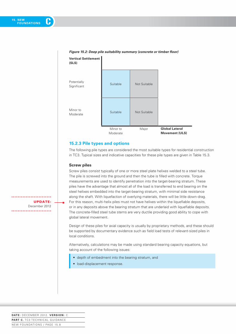
C2. FOUNDATION ASSESSMENT C15. NEW FOUNDATIONS
Figure 15.2: Deep pile suitability summary (concrete or timber floor)
Vertical Settlement (SLS)
Potentially Significant
Suitable Not Suitable
Minor to Moderate
Suitable Not Suitable
Minor to Moderate
Major Global Lateral Movement (ULS)
15.2.3 Pile types and optionsThe following pile types are considered the most suitable types for residential construction in TC3. Typical sizes and indicative capacities for these pile types are given in Table 15.3.
Screw pilesScrew piles consist typically of one or more steel plate helixes welded to a steel tube. The pile is screwed into the ground and then the tube is filled with concrete. Torque measurements are used to identify penetration into the target-bearing stratum. These piles have the advantage that almost all of the load is transferred to end bearing on the steel helixes embedded into the target-bearing stratum, with minimal side resistance along the shaft. With liquefaction of overlying materials, there will be little down-drag. For this reason, multi-helix piles must not have helixes within the liquefiable deposits, or in any deposits above the bearing stratum that are underlaid with liquefiable deposits. The concrete-filled steel tube stems are very ductile providing good ability to cope with global lateral movement.
Design of these piles for axial capacity is usually by proprietary methods, and these should be supported by documentary evidence such as field load tests of relevant-sized piles in local conditions.
Alternatively, calculations may be made using standard bearing capacity equations, but taking account of the following issues:
• depth of embedment into the bearing stratum, and
• load-displacement response.
UPDATE:December 2012
DAT E : D E C E M B E R 2 012 . V E R S I O N : C
PA RT C . T C 3 T E C H N I C A L G U I DA N C E
N E W F OU N DAT I O N S / PAG E 15 . 8
Canterbury Technical Guidance - PART C.indd 8 22/01/2013 11:19:31 a.m.
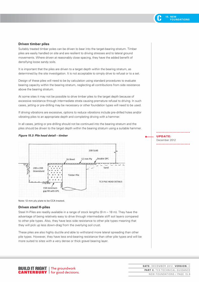
C 2. FOUNDATION ASSESSMENTC 15. NEW
FOUNDATIONS
Driven timber pilesSuitably treated timber poles can be driven to bear into the target-bearing stratum. Timber piles are easily handled on site and are resilient to driving stresses and to lateral ground movements. Where driven at reasonably close spacing, they have the added benefit of densifying loose sandy soils.
It is important that the piles are driven to a target depth within the bearing stratum, as determined by the site investigation. It is not acceptable to simply drive to refusal or to a set.
Design of these piles will need to be by calculation using standard procedures to evaluate bearing capacity within the bearing stratum, neglecting all contributions from side resistance above the bearing stratum.
At some sites it may not be possible to drive timber piles to the target depth because of excessive resistance through intermediate strata causing premature refusal to driving. In such cases, jetting or pre-drilling may be necessary or other foundation types will need to be used.
If driving vibrations are excessive, options to reduce vibrations include pre-drilled holes and/or vibrating piles to an appropriate depth and completing driving with a hammer.
In all cases, jetting or pre-drilling should not be continued into the bearing stratum and the piles should be driven to the target depth within the bearing stratum using a suitable hammer.
Figure 15.3: Pile head detail – timber
Note: 12 mm ply plate to be CCA treated.
Driven steel H-pilesSteel H-Piles are readily available in a range of stock lengths (9 m – 18 m). They have the advantage of being relatively easy to drive through intermediate stiff soil layers compared to other pile types. Also, they have less side resistance to other pile types meaning that they will pick up less down-drag from the overlying soil crust.
These piles are also highly ductile and able to withstand more lateral spreading than other pile types. However, they have less end-bearing resistance than other pile types and will be more suited to sites with a very dense or thick gravel bearing layer.
UPDATE:December 2012
DAT E : D E C E M B E R 2 012 . V E R S I O N : C
PA RT C . T C 3 T E C H N I C A L G U I DA N C E
N E W F OU N DAT I O N S / PAG E 15 . 9
Canterbury Technical Guidance - PART C.indd 9 22/01/2013 11:19:31 a.m.

C2. FOUNDATION ASSESSMENT C15. NEW FOUNDATIONS
It is important that the piles are driven to a target depth within the bearing stratum, as determined by the site investigation. It is not acceptable to simply drive to refusal or to a set.
Design of these piles will need to be by calculation using standard procedures to evaluate bearing capacity within the bearing stratum, neglecting all contributions from side resistance above the bearing stratum.
Figure 15.4: Pile head detail – steel
Note: 12 mm ply plate to be CCA treated.
Driven steel tubesSteel tubes are available in a wide range of sizes and stock lengths. Suitable sections should have sufficient wall thickness to be able to withstand driving stresses and structural loads. Tubes may be driven either closed-ended with welded base plates or open-ended. Open-ended piles may be easier to drive through intermediate hard layers but are more susceptible to damage if obstacles are encountered.
Steel tube piles should be concrete filled after installation making them highly ductile and able to withstand more lateral spreading than other pile types.
It is important that the piles are driven to a target depth within the bearing stratum, as determined by the site investigation. It is not acceptable to simply drive to refusal or to a set.
Design of these piles will need to be by calculation using standard procedures to evaluate bearing capacity within the bearing stratum, neglecting all contributions from side resistance above the bearing stratum, and including the effect of down-drag from non-liquefied soils.
UPDATE:December 2012
UPDATE:December 2012
DAT E : D E C E M B E R 2 012 . V E R S I O N : C
PA RT C . T C 3 T E C H N I C A L G U I DA N C E
N E W F OU N DAT I O N S / PAG E 15 . 10
Canterbury Technical Guidance - PART C.indd 10 22/01/2013 11:19:31 a.m.

C 2. FOUNDATION ASSESSMENTC 15. NEW
FOUNDATIONS
Driven precast concrete pilesConcrete piles can be manufactured to desired length and driven to bear in the target-bearing stratum. Where driven at reasonably close spacing, they have the added benefit of densifying loose sandy soils. The main limitation of precast concrete piles is limited ductility to withstand lateral ground movements, and piles will need to be specially detailed for ductility.
It is important that the piles are driven to a target depth within the bearing stratum, as determined by the site investigation. It is not acceptable to simply drive to refusal or to a set.
Design of these piles will need to be by calculation using standard procedures to evaluate bearing capacity within the bearing stratum, neglecting all contributions from side resistance above the bearing stratum.
At some sites it may not be possible to drive precast concrete piles to the target depth because of excessive resistance through intermediate strata causing premature refusal to driving. In such cases, jetting or predrilling may be necessary or other foundation types will need to be used.
In all cases, jetting or pre-drilling should not be continued into the bearing stratum and the piles should be driven to the target depth within the bearing stratum.
Figure 15.5: Pile head detail – concrete
Note: 12 mm ply plate to be CCA treated.
The following pile types are considered less suitable for residential construction in TC3. These are not precluded from use, but will require additional engineering input to ensure satisfactory performance.
Continuous flight augur piles (CFA)CFA piles are formed by first screwing a hollow-stemmed augur into the ground to the target depth, then slowly withdrawing the augur while high-slump concrete is pumped down the hollow stem to form the pile. Special monitoring equipment is required to ensure that the concrete flow rate matches the withdrawal rate of the augur to prevent formation of voids. A steel reinforcing cage is inserted immediately after the final withdrawal of the augur.
UPDATE:December 2012
DAT E : D E C E M B E R 2 012 . V E R S I O N : C
PA RT C . T C 3 T E C H N I C A L G U I DA N C E
N E W F OU N DAT I O N S / PAG E 15 . 11
Canterbury Technical Guidance - PART C.indd 11 22/01/2013 11:19:31 a.m.
C2. FOUNDATION ASSESSMENT C15. NEW FOUNDATIONS
These piles are considered less suitable because they typically have a high side-resistance capacity, and initial load transfer after construction will be mostly by side-resistance, including through the liquefiable strata. During liquefaction, most side resistance will be lost and will have to be transferred to end bearing – a relatively soft mechanism that can induce settlements as the load is transferred to the base of the pile.
The settlement in this case needs to be checked carefully, including the added load from down-drag. Settlement may be controlled by embedding the piles deeper into the bearing stratum.
Design of these piles will need to be by calculation using standard procedures to evaluate bearing capacity within the bearing stratum, neglecting all contributions from side resistance above the bearing stratum, and including the effect of down-drag from non-liquefied soils.
These piles will also need to be specially detailed for ductility to prevent brittle shear failure from lateral soil movements.
Bored pilesBored holes for cast-in-place concrete piles will generally be unstable in TC3 areas and will require temporary support using steel casings or drilling slurries and will need to be poured using a tremie. These techniques are unlikely to be economical for residential construction.
These piles are considered less-suitable because they typically have a high side-resistance capacity, and initial load transfer after construction will be mostly by side-resistance, including through the liquefiable strata. During liquefaction, most side resistance will be lost and will have to be transferred to end bearing – a relatively soft mechanism which can induce settlements as the load is transferred to the base of the pile.
The settlement in this case needs to be checked carefully, including the added load from down-drag. Settlement may be controlled by embedding the piles deeper into the bearing stratum.
Design of these piles will need to be by calculation using standard procedures to evaluate bearing capacity within the bearing stratum, neglecting all contributions from side resistance above the bearing stratum, and including the effect of down-drag from non-liquefied soils.
MicropilesMicropiles are small diameter piles and include both driven and bored varieties. The main drawback of micropiles in this situation is that they typically achieve most of their load capacity from side resistance with relatively small end-bearing capacity. Therefore, they will need to penetrate well into the target-bearing stratum to achieve sufficient capacity after neglecting the side resistance through the liquefiable strata and taking into accouint the effects of down-drag.
15.2.4 Particular geotechnical investigation requirementsWhere deep pile foundations are being considered at a site, it will be necessary to carry out a deep site investigation. The objective is to identify a suitable bearing stratum with the minimum characteristics identified above. In addition, it is necessary to identify the thickness of the surface crust and other non-liquefying layers to be able to assess the most suitable pile type and any issues with driving and down-drag.
DAT E : D E C E M B E R 2 012 . V E R S I O N : C
PA RT C . T C 3 T E C H N I C A L G U I DA N C E
N E W F OU N DAT I O N S / PAG E 15 . 12
Canterbury Technical Guidance - PART C.indd 12 22/01/2013 11:19:31 a.m.

C 2. FOUNDATION ASSESSMENTC 15. NEW
FOUNDATIONS
The following investigation strategy is recommended:
1. Carry out CPT at site (refer section 13).
2. If the profile appears to meet the general requirements for deep pile foundations, continue with a second CPT to provide confidence that bearing stratum extends across the footprint.
3. If the CPT is unable to prove the minimum thickness required for a bearing layer, then a machine borehole with SPTs at 1 m or 1.2 m centres is required to prove the minimum thickness of the bearing layer.
15.2.5 Design approaches and parametersDeep pile foundations will need specific engineering design in all cases, given the complexities of identifying a suitable bearing layer, calculation of bearing capacity, and lateral loading. The design of the floor slab supported by the pile system also requires careful consideration.
PilesThe objective of using pile foundations is to limit settlement of the building independent from settlement and deformation of the ground above the bearing stratum. Calculation of pile load-deformation response in each individual situation is complex and generally excessive for a residential building. Building weights are likely to be low and pile sizes small, so a simplified procedure is recommended based on standard limiting equilibrium strength calculations and a conservative strength reduction factor. This procedure is:
1. Sum the ULS-factored gravity building loads.
2. Calculate ideal vertical capacity of pile embedded in target bearing stratum (from only that part of pile embedded within the target bearing stratum) using standard limiting equilibrium procedures.
3. Apply Фg = 0.4 (intended to both provide reliable capacity and also limit settlements)
The design equation becomes:
Ф gRu {in bearing stratum} ≥1.2G +1.5Q
For this simplified design procedure (for driven piles for residential buildings only) the down-drag forces acting on the pile above the bearing stratum may be ignored. If bored piles or CFA piles are being considered, then the down-drag forces should be added to the factored gravity loads and the effects of loss of side resistance with liquefaction should be carefully considered.
It is assumed that if the above design procedure is followed for the ULS case, then it will not be necessary to separately consider the SLS case. If liquefaction is triggered for the SLS case, then the above design procedure should limit settlement to 25 mm or less.
Kinematic effects (lateral soil-pile interactions) do not need to be explicitly considered in each case for the pile types indicated as being most suitable. Analysis of these pile types has shown that they should be able to withstand lateral surface movement of up to 300 mm for typical situations (see Table 15.3 for details). If the less suitable pile types are to be used, designers will need to demonstrate their ability to withstand a lateral surface movement of 300 mm while maintaining an ability to continue to support the
DAT E : D E C E M B E R 2 012 . V E R S I O N : C
PA RT C . T C 3 T E C H N I C A L G U I DA N C E
N E W F OU N DAT I O N S / PAG E 15 . 13
Canterbury Technical Guidance - PART C.indd 13 22/01/2013 11:19:31 a.m.

C2. FOUNDATION ASSESSMENT C15. NEW FOUNDATIONS
building and be reusable for a repaired structure. The results shown in Table 15.3 are based on an assumed thickness for the liquefied layer of 6 m. If the liquefied layer at a site is significantly thinner than 6 m then the ability of piles to accommodate global lateral movement will be reduced and designers should make their own assessment of kinematic effects.
Pile buckling within liquefied soil layers does not need to be considered explicitly for the most suitable pile types for the typical conditions considered in Table 15.3. Pile buckling may be an issue for heavily loaded, slender piles within very thick liquefied layers. Additional guidance is given in Bhattacharya et.al. (2004).
Simplified design procedures for driven piles based on SPT and CPT results are given in Appendix C3.
Table 15.3 summarises typical available pile sizes and corresponding indicative capacities. Figures 15.6 and 15.7 show layouts and sample detailing for a flat concrete slab on deep piles and Figures 15.8 and 15.9 show layouts and sample detailing for a waffle slab on deep piles.
Table 15.3: Typical pile sizes and indicative capacities
Pile TypeScrew
PileDriven Timber
Driven H-Pile
Driven Steel Tube
(Concrete filled, closed
end)
Driven Concrete
Driven Concrete
Typical size 300 Helix x 150 NB
250 SED 200 UC 200 CHS 150 x 150 200 x 200
Load capacity1 95 KN 90 KN 75 KN 70 KN 95 KN
Lateral displacement2
300 mm 300 mm 300 mm 300 mm 300 mm3 300 mm3
Advantages Minimal down drag,
very high ductility
Cheap, light,
readily available
Good ductility, penetrate
hard layers, reduced
down-drag
Very high ductility
Cast to required length
Cast to required length
Disadvantages Limited contractor capacity
Difficulty penetrating
dense layers
Relatively expensive
Relatively expensive
Limited ductility;
need length certain prior to
fabrication; difficult to
splice
Limited ductility;
need length certain prior to
fabrication; difficult to
splice
Note:
1. Dependable capacity embedded 1 m into N60 = 25 sand or gravel. Higher capacities will be obtainable in denser soil or deeper embedment.
2. Ability to withstand global lateral movement assuming 2 m thick stiff crust and 6 m thick liquefied layer.
3. Special detailing for ductility required. Assessment based on proprietary design of Hi-Stress Concrete Ltd. Other pile designs will require specific analysis.
UPDATE:December 2012
DAT E : D E C E M B E R 2 012 . V E R S I O N : C
PA RT C . T C 3 T E C H N I C A L G U I DA N C E
N E W F OU N DAT I O N S / PAG E 15 . 14
Canterbury Technical Guidance - PART C.indd 14 22/01/2013 11:19:31 a.m.

C 2. FOUNDATION ASSESSMENTC 15. NEW
FOUNDATIONS
Slab on pilesSlabs should be designed to span over the piles, ie, not requiring support from the soils beneath the slabs.
Two sample slab options have been designed to be supported on the deep piles. The first is a solid 200 mm thick slab and the second is a waffle slab (refer Figures 15.6 and 15.8). These options are adapted from TC2 foundation options 2 and 4 respectively in Part A, section 5.3.1.
The beams of the waffle slab are 500 mm wide to provide space for pile head details.
For situations where significant lateral stretch of up to 200 mm has occurred across the footprint or is considered likely to occur, the special sliding pile head details shown in Figures 15.3, 15.4 and 15.5 should be used.
Figure 15.6: Illustrative pile layout for a flat concrete slab
UPDATE:December 2012
DAT E : D E C E M B E R 2 012 . V E R S I O N : C
PA RT C . T C 3 T E C H N I C A L G U I DA N C E
N E W F OU N DAT I O N S / PAG E 15 . 15
Canterbury Technical Guidance - PART C.indd 15 22/01/2013 11:19:32 a.m.

C2. FOUNDATION ASSESSMENT C15. NEW FOUNDATIONS
Figure 15.7: Section A-A – Illustrative pile layout for a flat concrete slab
Figure 15.8: Illustrative layout and sample details for a waffle slab on deep pile
UPDATE:December 2012
DAT E : D E C E M B E R 2 012 . V E R S I O N : C
PA RT C . T C 3 T E C H N I C A L G U I DA N C E
N E W F OU N DAT I O N S / PAG E 15 . 16
Canterbury Technical Guidance - PART C.indd 16 22/01/2013 11:19:32 a.m.

C 2. FOUNDATION ASSESSMENTC 15. NEW
FOUNDATIONS
Figure 15.9: Sample detail for a waffle slab on deep piles
15.2.6 Specification and construction issuesDeep piles require a good level of resilience (timber) or ductility (steel and concrete) to be able to cope with the required minimum level of global lateral movement. Timber piles and screw piles (concrete-filled steel tubes) and steel H-piles and tubes are considered to have sufficient resilience or ductility for sites with moderate potential for global lateral movement. Concrete piles, either driven precast or cast insitu (eg, CFA), will require special detailing for ductility.
At sites with major potential for lateral movement, all pile types will require specific design and detailing to ensure that they can withstand the expected lateral movements without suffering a brittle shear failure.
Piles must be specified to be installed to the target depth established from the site investigation by the engineer. For driven piles, the required driving energy to achieve the necessary penetration should be estimated and suitable pile-driving equipment should be specified accordingly.
Difficulties may arise during installation from intermediate hard layers that are difficult to penetrate. These hard layers should be identified during the investigation and taken into account when assessing the suitability of any particular pile type and driving equipment. Predrilling through such layers should generally be acceptable and may be beneficial in reducing the amount of down-drag on the piles. However, pre-drilling should not extend into the bearing layer, and the pile should be driven to target depth in the bearing layer using a suitable hammer.
Leaving piles bearing on to intermediate hard layers because of an inability to penetrate to the target layer is not acceptable.
It is likely that after an earthquake event, the ground surface will settle relative to the piled building. Service connections will require special detailing to ensure that they are able to cope with the expected relative movement.
UPDATE:December 2012
DAT E : D E C E M B E R 2 012 . V E R S I O N : C
PA RT C . T C 3 T E C H N I C A L G U I DA N C E
N E W F OU N DAT I O N S / PAG E 15 . 17
Canterbury Technical Guidance - PART C.indd 17 22/01/2013 11:19:33 a.m.

C2. FOUNDATION ASSESSMENT C15. NEW FOUNDATIONS
DAT E : D E C E M B E R 2 012 . V E R S I O N : C
PA RT C . T C 3 T E C H N I C A L G U I DA N C E
N E W F OU N DAT I O N S / PAG E 15 . 18
Canterbury Technical Guidance - PART C.indd 18 22/01/2013 11:19:33 a.m.

C 2. FOUNDATION ASSESSMENTC 15. NEW
FOUNDATIONS
15.3 Site ground improvement
For an overview summary, see Table 15.4 and 15.9 on pages 65 and 66.
15.3.1 Objectives and scopeThere are a number of ground improvement methods available for mitigation of the effects of liquefaction induced by seismic shaking. Design of these methods may be undertaken using procedures listed below, but their use will depend on their applicability to the specific site conditions.
In 2011 the Department of Building and Housing (now the Ministry of Business, Innovation and Employment) commissioned a field trial of a number of ground improvement options. During the field trial the selected options were subjected to simulated ULS levels of shaking, and the performance of each of the mitigation methods was assessed by reference to measured settlements, ground vibration and pore pressure response. The testing programme was internationally both unique and significant. It is, however, acknowledged that this was still in some ways a limited testing programme. Once built solutions have been tested ground improvement options can be refined. The results of these field tests can be accessed on the following website: https://canterburyrecovery.projectorbit.com/Shared/QE2%20Trial.pdf
The field trial has provided a measure of the expected performance of these mitigation options in typical Christchurch liquefaction-prone soils, and this has been used to develop the design guidance in this section.
This section provides guidance for deciding whether a particular TC3 site is suitable for using one of the options that were part of the Department’s trial, and also provides more general comment on the application of other methods of ground remediation works. Outline method statements for the options covered in these guidelines are included in Appendix C4.
It is intended that ground improvement carried out following these guidelines will allow the construction of either concrete or timber floors that are supported on foundations that meet the requirements of TC2. In TC3, the plan shape of the site ground improvements should be sufficiently regular. The basic requirements for these foundations are set out in Part A, sections 5.3.1 and 5.3.2 (for concrete and timber respectively). The concrete slab Options 2 to 4 or timber floors from section 5.3 of the guidance can accommodate all but two or more storey houses with heavy-weight cladding extending over two or more storeys.
Based on the field trials, at this stage some of the ground treatment options are limited to sites similar to the test site ie, depth of liquefiable materials limited to a maximum 10 m under ULS conditions. This limitation option does not apply to some of the deeper treatment options.
UPDATE:December 2012
DAT E : D E C E M B E R 2 012 . V E R S I O N : C
PA RT C . T C 3 T E C H N I C A L G U I DA N C E
N E W F OU N DAT I O N S / PAG E 15 . 19
Canterbury Technical Guidance - PART C.indd 19 22/01/2013 11:19:33 a.m.
C2. FOUNDATION ASSESSMENT C15. NEW FOUNDATIONS
15.3.2 Improvement types and optionsThe following is a list of the more commonly used methods of ground improvement. There are many variants, but they can be generally grouped as follows:
• densification of either the crust layer and/or the deeper liquefiable soils. This includes methods such as compaction, excavation and replacement/recompaction, vibroflotation, preloading, dynamic compaction (DC), and rapid impact compaction
• crust strengthening/stabilisation by permeation grouting, stabilisation mixing or replacement
• deep strengthening using deep soil-cement mix piles, jet grouting, stone columns, close spaced timber or precast piles
• containment by ground reinforcement or curtain walls
• drainage using stone columns or earthquake drains.
Most of these methods require clear access to the treated zone ie, greenfield site, demolition or temporary removal of the existing dwelling. The containment method, some methods of injection grouting, jet grouting and permeation grouting provide opportunities to achieve improved ground performance without removal of the existing structure.
The methods used in the Department’s trial were representative of the densification, crust strengthening, deep strengthening and containment groups of methods. All methods apart from the containment method provided significant improvement to the ground performance.
The following methods are currently included in these guidelines:
• Type 1 – Densified raft (ie, recompacted soil or replacement fill; also dynamic compaction or rapid impact compaction).
• Type 2 – Stabilised crust (ie, cement-mixed soils, either by excavate and replace or insitu mixing).
• Type 3 – Deep soil mixing (ie, soil mixed or jet-grouted columns).
• Type 4 – Stone columns.
• Type 5 – Low mobility grout columns.
Some or all of these methods may require a resource consent. In particular, noise and vibration effects should be considered.
15.3.3 General geotechnical investigation requirementsThe selection of any ground improvement options in TC3 should be made on the basis of adequate geotechnical investigations on the site. This should include good quality information on the soil types, geotechnical properties and the depth to groundwater. Supplementary testing may be required for detailed design.
There will be limitations on the use of some methods where conditions are highly variable, where peat or high plasticity soil layers are present, and where steep interfaces occur between subsurface layers.
DAT E : D E C E M B E R 2 012 . V E R S I O N : C
PA RT C . T C 3 T E C H N I C A L G U I DA N C E
N E W F OU N DAT I O N S / PAG E 15 . 2 0
Canterbury Technical Guidance - PART C.indd 20 22/01/2013 11:19:33 a.m.

C 2. FOUNDATION ASSESSMENTC 15. NEW
FOUNDATIONS
The following general requirements are necessary for a site to be considered suitable for ground improvement in TC3:
1. Assessment of deep geotechnical information should be undertaken as outlined in section 13 of this document to support the remediation design.
2. Additional shallow site specific investigations should be undertaken as necessary to confirm the soil properties required for design of the selected method of ground remediation.
3. Investigations should be adequate to determine that soil types are suitable to respond to the selected methods, and the treated zones are sufficiently uniform that the method is not compromised by variations within the soil layers.
4. Adequate access must be available for plant to operate safely and effectively on the site.
5. Potential effects on adjacent sites must meet Council requirements, eg, groundwater extraction, sediment control, settlement, vibration and noise effects.
6. If the site is identified as being at risk of major or severe lateral spreading, the ground improvement works may need to address this – see section 12.2 and Table 15.4.
Note: Any increase in ground density or disturbance to the ground may result in settlements and change in ground permeability.
15.3.4 Specification, construction and verification issuesSpecific requirements for each of the options which provide adequate solutions are set out in this section. These methods are generally currently applicable to sites where the depth of liquefiable materials is limited to 10 m below the ground surface. However, for the deep treatment options (ie, deep soil-mixed columns, jet-grouted columns, stone columns and LMG columns) if the liquefiable deposits extend beyond this limit, the methods are still applicable as long as the depth of treatment extends to at least 8 m, and then additionally to the depth beyond which calculated ULS settlements under the zone of treatment are less than 100 mm, and calculated SLS settlement are less than 50 mm.
Alternatively, where the depth of liquefiable materials exceeds 10 m, shallow method Types 1 and 2 can still be used under the following circumstances:
• where treatment extends to 2 m outside the foundation line, AND
• where insitu methods are used then a geogrid should be installed at a depth of 0.5 m (noting that the excavate and replace options already include a geogrid at the base); AND
• where a Type 1 or Type 2 timber floor surface structure (only) is constructed.
Detailed model specifications/method statements for these methods are included in Appendix C4.
UPDATE:December 2012
DAT E : D E C E M B E R 2 012 . V E R S I O N : C
PA RT C . T C 3 T E C H N I C A L G U I DA N C E
N E W F OU N DAT I O N S / PAG E 15 . 2 1
Canterbury Technical Guidance - PART C.indd 21 22/01/2013 11:19:33 a.m.

C2. FOUNDATION ASSESSMENT C15. NEW FOUNDATIONS
Shallow foundation treatments:Densified raft of recompacted soil or replacement fill (Types 1a, 1b and 1c)
This method requires a densified block of soil to a depth of 2 m or more to be formed beneath the foundation elements. This will generally be achieved by either excavation of the subsoils and recompaction (or replacement with imported materials), or by Dynamic Compaction (or Rapid Impact Compaction). This method is considered suitable where the depth of liquefiable materials is limited to 10 m below the ground surface.
Excavation and replacement may be used on sites where excavation and temporary drawdown of the water table is possible and there is sufficient space to stockpile and manage the materials. The following also apply:
1. The construction of a dense raft to a minimum depth of 2 m must comprise materials that do not include significant organics and can be compacted to achieve a minimum density of greater than 95% standard compaction and penetration resistance of 7 blows/100 mm as measured by a Dynamic (Scala) penetrometer or equivalent.
2. The excavation base should extend at least 1 m beyond the footprint of the proposed structure. The sides of any excavation should be formed or supported to provide access and adequate safe working conditions for workers entering the area.
3. If the material is to be excavated and recompacted/replaced, the site may require temporary dewatering by installation of sumps or shallow well pointing. The potential effects on neighbouring properties need to be considered and these works may require specific consents unless they are permitted as part of the building consent.
4. The base of the excavation should be sufficiently drained to enable the surface to be compacted (with blinding placed if necessary) to enable two layers of triaxial geogrid (separated by 200 mm of compacted fill) to be placed over the excavation and extending up the sides by at least 1 m, plus sufficient length to enable a 3 m return as shown on Figures 15.10 and 15.11.
5. The replaced fill material is to be compacted with a static roller in 200 mm deep layers and prescribed testing undertaken to enable certification of the material. Vibratory compaction methods may be used when sufficiently clear of the water level to avoid fluidising or heaving the ground.
6. This method (by excavate and recompact) is unlikely to be economic if site geometry is such that sheetpiling is required, or large quantities of imported hardfill are needed.
The above requirements generally apply to the other methods of densification, but they may have specific requirements to achieve an equivalent dense raft. For example, for dynamic compaction or rapid impact methods, it is expected that energy levels for a target depth of about 4 m (without the inclusion of geogrids) will be applied ie, about 50 t-m of drop energy for dynamic compaction. The potential impacts on neighbouring properties and services need to be carefully considered. Three method statements for a Densified Crust are included in Appendix C4.
UPDATE:December 2012
DAT E : D E C E M B E R 2 012 . V E R S I O N : C
PA RT C . T C 3 T E C H N I C A L G U I DA N C E
N E W F OU N DAT I O N S / PAG E 15 . 2 2
Canterbury Technical Guidance - PART C.indd 22 22/01/2013 11:19:33 a.m.

C 2. FOUNDATION ASSESSMENTC 15. NEW
FOUNDATIONS
Figure 15.10: Densified crust (Type 1a)
DAT E : D E C E M B E R 2 012 . V E R S I O N : C
PA RT C . T C 3 T E C H N I C A L G U I DA N C E
N E W F OU N DAT I O N S / PAG E 15 . 2 3
Canterbury Technical Guidance - PART C.indd 23 22/01/2013 11:19:34 a.m.

C2. FOUNDATION ASSESSMENT C15. NEW FOUNDATIONS
Figure 15.11: Densified crust – strips or partial cut (Type 1a)
DAT E : D E C E M B E R 2 012 . V E R S I O N : C
PA RT C . T C 3 T E C H N I C A L G U I DA N C E
N E W F OU N DAT I O N S / PAG E 15 . 2 4
Canterbury Technical Guidance - PART C.indd 24 22/01/2013 11:19:34 a.m.

C 2. FOUNDATION ASSESSMENTC 15. NEW
FOUNDATIONS
Stabilised crust (Types 2a and 2b)This method will provide a cement-stabilised block of soil to a depth of 2 m beneath the foundation elements. This will generally be achieved by either:
• excavation of the subsoils, mixing with cement and recompaction in place, or
• by mechanical mixing insitu the cement with the soil using a panel mixer or rotary cutter machine from the surface.
The first option (excavate, mix and recompact) is unlikely to be economic if site geometry is such that sheet piling is required, or large quantities of imported fill are needed.
This method is considered suitable where the depth of liquefiable materials is limited to 10 m below the ground surface.
The construction of a stabilised crust may be undertaken by any of the following methods:
• excavation to 2 m depth, mixing of 3% cement (by weight) and placement to engineered standards (applies to sites with at least 2 m of clean sandy soils where the groundwater can be temporarily lowered to 2 m depth and there is adequate space for handling of materials; organics should be separated and disposed of offsite).
• excavation and disposal of soil to 2 m depth, replacement with cohesionless soil stabilised with 3% cement (by weight) and compaction to engineered standards
(applies to sites which contain high organic or excessively fine-grained soils in the upper 2 m and where the groundwater can be temporarily lowered to 2 m depth).
• insitu stabilisation with 5% cement (by weight) to 2 m depth and surface compaction with a heavy static roller
(applies to sandy soil sites where organic content is less than 5% by volume; groundwater lowering is not required).
The following requirements are expected to apply for the first two excavation and compaction methods (refer to the method statement provided in Appendix C4 (Types 2a and 2b):
1. The stabilised area should extend to at least 1 m beyond the building footprint.
2. If excavation methods are used, the sides should be formed or supported to provide safe access and working conditions within the excavation.
3. The base of the excavation should be drained to provide a working surface. This may require the use of temporary sumps or well pointing which may necessitate separate consent unless permitted as part of the building consents. The potential effects of drawdown on neighbouring properties need to be considered.
4. The base of the excavation should be compacted with a static roller and the fill placed in 200 mm layers compacted to achieve a minimum of 90% standard compaction and a penetration resistance of 7 blows/100 mm as measured by a dynamic (Scala) penetrometer or equivalent within 2 hours after the placement and compaction of the fill.
5. The engineer may specify a geotextile separation layer at the base of the excavation to provide an improved working surface.
UPDATE:December 2012
DAT E : D E C E M B E R 2 012 . V E R S I O N : C
PA RT C . T C 3 T E C H N I C A L G U I DA N C E
N E W F OU N DAT I O N S / PAG E 15 . 2 5
Canterbury Technical Guidance - PART C.indd 25 22/01/2013 11:19:34 a.m.
C2. FOUNDATION ASSESSMENT C15. NEW FOUNDATIONS
6. If this solution is being used in ‘Major’ lateral stretch zones, then two layers of geogrid are to be incorporated in the same manner as described above for densified rafts of recompacted soils (Type 1a).
7. If the soils contain high clay/silt fines, stabilisation may be more effective if a combination of lime (2%) and cement (3%) is applied.
If insitu mixing is applied, it is expected to be undertaken with a panel mixer or rotary cutter equipment. Refer to the method statement provided in Appendix C4 (Type 2b). It is generally suitable for all sites where there are low levels of organic soils present (less than 5% by volume) in the upper 2 m of soil .The following recommendations are made:
1. The stabilised area should extend to at least 1.5 m beyond the building footprint.
2. The method of mixing should ensure uniform distribution and mixing of the cement. Overlaps of the treated strips must be adequate to ensure there are no untreated zones.
3. An overall dose rate of 5% of cement by weight is recommended.
4. Quality systems are to be in place and must record quantities of cement used, points of sampling, and test information.
5. Testing at 7 days to ensure the strength of the stabilised layer exceeds one of the following:
i. Unconfined compressive strength of 1 MPa on a concrete cylinder sample compacted, cured and tested in accordance with NZS 311: 1986.
ii. Soaked CBR of Field CBR exceeding 25.
iii. Uncorrected SPT or Heavy Dynamic Penetrometer Test (DPT) of N > 20.
iv. CPT qc > 6 MPa.
v. Scala Penetrometer C > 10 blows/100 mm.
6. The surface of the treated area is to be compacted and sealed using a static roller on completion of the work.
UPDATE:December 2012
DAT E : D E C E M B E R 2 012 . V E R S I O N : C
PA RT C . T C 3 T E C H N I C A L G U I DA N C E
N E W F OU N DAT I O N S / PAG E 15 . 2 6
Canterbury Technical Guidance - PART C.indd 26 22/01/2013 11:19:34 a.m.

C 2. FOUNDATION ASSESSMENTC 15. NEW
FOUNDATIONS
Figure 15.12: Stabilised crust (Type 2a)
DAT E : D E C E M B E R 2 012 . V E R S I O N : C
PA RT C . T C 3 T E C H N I C A L G U I DA N C E
N E W F OU N DAT I O N S / PAG E 15 . 2 7
Canterbury Technical Guidance - PART C.indd 27 22/01/2013 11:19:35 a.m.

C2. FOUNDATION ASSESSMENT C15. NEW FOUNDATIONS
Figure 15.13: Stabilised crust – strips or partial cut (Type 2a)
DAT E : D E C E M B E R 2 012 . V E R S I O N : C
PA RT C . T C 3 T E C H N I C A L G U I DA N C E
N E W F OU N DAT I O N S / PAG E 15 . 2 8
Canterbury Technical Guidance - PART C.indd 28 22/01/2013 11:19:35 a.m.

C 2. FOUNDATION ASSESSMENTC 15. NEW
FOUNDATIONS
Deep foundation treatments:Deep soil mixing (Type 3)
This method will provide a relatively deep zone of ground improvement that will reduce soil shear strains during seismic events and therefore reduce the severity of liquefaction.
This method is generally applicable for all soil types provided there are no peat zones or organic materials that exceed 5% by volume. They are normally constructed by jet grouting or are injected by a rotary auger rig. Refer to the method statement provided in Appendix C4 (Type 3).
The following specific recommendations are made:
1. The treated area must extend to a minimum of 1.5 m outside the building footprint.
2. The jet grouting or deep soil mix columns layout must be targeted to achieve ground treatment of 16-20% of the area of the site (typically 900–1000 mm diameter columns on a 2 m grid – this allows for grout to extend beyond an immediate 800 mm column).
3. The columns must extend to a minimum depth of 8 m below ground level or be founded in dense sands or gravels which are proven to be continuous for at least 2 m. Where the depth of liquefiable materials extends further than 10 m, the treatment should extend to at least 8 m and then additionally to the depth beyond which calculated ULS settlements under the zone of treatment are less than 100 mm, and calculated SLS settlement are less than 50 mm.
4. The cement dose rate should be a minimum of 10% by weight. Representative samples are to be taken at a rate of 1 cylinder per 50 m3 of column volume, and tested at 7 days to achieve a minimum (95% confidence limit) unconfined compressive strength of 1 MPa.
5. The quality system shall record details of the grid and progress of the works, the quantity of cement used, sampling points and test results.
6. The surface of the treated area is to be levelled and compacted at the completion of the works.
Stone columns (Type 4)
Stone columns were not included in the Department’s trial but the method has been used at a number of sites in Christchurch from which the performance can be assessed. The following specific requirements which form the basis of the method statement provided in Appendix C4 (Type 4) are recommended.
1. Stone columns may be used on sites with less than 5% by volume of peat and organic soils.
2. Stone columns should target a replacement rate of 18-20% (typically 800 mm diameter on a 1.75 m grid).
3. Stone materials should be uniformly graded, low-fines aggregate, crushed concrete or other approved material with at least two broken faces.
DAT E : D E C E M B E R 2 012 . V E R S I O N : C
PA RT C . T C 3 T E C H N I C A L G U I DA N C E
N E W F OU N DAT I O N S / PAG E 15 . 2 9
Canterbury Technical Guidance - PART C.indd 29 22/01/2013 11:19:35 a.m.

C2. FOUNDATION ASSESSMENT C15. NEW FOUNDATIONS
4. Depth of columns should be determined by the engineer but is expected to be a minimum of 8 m below ground level unless terminated in dense non-liquefiable soils proven to 2 m depth. Where the depth of liquefiable materials extends further than 10 m, the treatment should extend to at least 8 m and then additionally to the depth beyond which calculated ULS settlements under the zone of treatment are less than 100 mm, and calculated SLS settlement are less than 50 mm
5. The quality system must record layout of columns, progress of the works, and quantity of stone used.
6. Mid-point testing shall comprise CPT, or continuous SPT or DPT at a rate of 1 probe per 100 m2. Refer to the method statement in Appendix C4 for details.
Low mobility grout columns (Type 5)
This Low Mobility Grout (LMG) method was not included in the Department’s trial, but is a variant of Deep Soil Mixing which also achieves densification of the ground. It is generally applicable for all soil types. The columns are normally constructed by driving a small diameter casing to a non-liquefiable layer, and the formation of a series of ‘stacked’ bulbs by injection of a low slump, low mobility grout. The method may be also used to relevel the ground and raise overlying structures. Refer to the method statement provided in Appendix C4 (Type 5).
The following specific recommendations are made:
1. The treated area must extend to a minimum of 1.5 m outside the building footprint
2. The LMG columns layout must be targeted to achieve ground treatment of 12-15% of the area of the site (typically 800 mm diameter columns on a 2 m grid). Other combinations are possible. The maximum spacing of columns is 3 m.
3. The columns must extend to a minimum depth of 8 m below ground level or be founded in dense sands or gravels which are proven to be continuous for at least 2 m. Where the depth of liquefiable materials extends further than 10 m, the treatment should extend to at least 8 m and then additionally to the depth beyond which calculated ULS settlements under the zone of treatment are less than 100 mm, and calculated SLS settlement are less than 50 mm.
4. The grout should be designed to a minimum 15 MPa strength at 7 days. Representative samples are to be taken at a rate of 1 cylinder per 50 m3 of column volume, and tested at 7 days to achieve a minimum (95% confidence limit) unconfined compressive strength of 15 MPa.
5. The quality system shall record details of the grid and progress of the works, the quantity of cement used, sampling points and test results. If relevelling of structures is to be undertaken, survey control points are to be monitored and the works undertaken in accordance with a site-specific specification.
6. The exposed surface of the treated area is to be levelled and compacted at the completion of the works.
DAT E : D E C E M B E R 2 012 . V E R S I O N : C
PA RT C . T C 3 T E C H N I C A L G U I DA N C E
N E W F OU N DAT I O N S / PAG E 15 . 3 0
Canterbury Technical Guidance - PART C.indd 30 22/01/2013 11:19:35 a.m.

C 2. FOUNDATION ASSESSMENTC 15. NEW
FOUNDATIONS
SummaryA summary of the applicability and suitability of ground improvement with respect to various situations of water table and presence of organic material, and the different levels of lateral stretch and vertical settlement is provided in Table 15.4 and Figure 15.14.
Table 15.4: Relevant ground improvement methods
Type Description
Considerations
Organics >5%
Water Table <1 m (no
dewatering)
Dewatering to 2 m below ground
level
Stockpile area
required?
Use in Major lateral stretch zones
Depth to dense non liquefiable zone >10 m
Shallow treatments
1a
Densified Crust – excavate and backfill
YSpecific
engineering design
Required Required N/A* N*
1b
Densified crust – dynamic compaction
N N Not requiredNot
requiredN N*
1cRapid impact compaction
N N Not requiredNot
requiredN N*
2a
Stabilised crust (Excavate, mix and replace)
Y N Required RequiredY (with geogrid)
N*
N/A*
2bStabilised crust (In place mixing)
N Y Not requiredNot
requiredN N*
Deep treatments
3Deep soil mixing
N Y
Not required
Not required
Y Y
4Stone columns
N Y Required N/A* Y
5Low mobility grout
Y YNot
requiredN/A* Y
Notes:
Y= Method suitable.
N = Method not suitable
N/A* denotes outside the scope of application of this guidance but could be applicable with specific detailed engineering design input. In major lateral spread zones some restrictions on foundation types apply (see Table 15.2).
N* Not suitable unless restrictions outlined in Part C, section 5.3.4 adhered to.
UPDATE:December 2012
DAT E : D E C E M B E R 2 012 . V E R S I O N : C
PA RT C . T C 3 T E C H N I C A L G U I DA N C E
N E W F OU N DAT I O N S / PAG E 15 . 3 1
Canterbury Technical Guidance - PART C.indd 31 22/01/2013 11:19:36 a.m.

C2. FOUNDATION ASSESSMENT C15. NEW FOUNDATIONS
Figure 15.14: Ground improvement suitability summary (concrete or timber floor
Vertical Settlement (SLS)
Potentially Significant
SuitableTypes 2a & 3 Suitable
Minor to Moderate
SuitableTypes 2a & 3 Suitable
Minor to Moderate
Major Lateral Stretch (ULS)
Note: Ground Improvement Types 1a, 4 and 5 can be used in areas of major lateral stretch with specific geotechnical engineering design
15.3.5 Service trenches and pavementsWhere services or other excavations are required in the treated (densified or stabilised) zone, care should be taken to minimise disturbance to the surrounding materials. Granular backfill is to be placed in 200 mm thick layers with the addition of 3% cement by weight and the materials are to be well compacted to achieve a dense surface. If excavations extend to within 500 mm of the edge of the treated zone, the excavation should extend to the edge and the ground be made good as with the trench backfill.
Where service interfaces occur between the treated and untreated ground, detailing should consider the potential for differential movements by including flexible or piped sections and extension of the cement-treated backfill to form a transition zone.
Where pavements are to be constructed beyond the treated zone, a transition may be provided by treating a 300-500 mm deep subgrade, by addition of 3% cement by weight, and including construction joints at any interfaces that are formed.
In general, penetrations of the crust should be minimised because they may form a zone of weakness that provides a release path for surface expulsion of liquefied soil.
DAT E : D E C E M B E R 2 012 . V E R S I O N : C
PA RT C . T C 3 T E C H N I C A L G U I DA N C E
N E W F OU N DAT I O N S / PAG E 15 . 3 2
Canterbury Technical Guidance - PART C.indd 32 22/01/2013 11:19:36 a.m.
C 2. FOUNDATION ASSESSMENTC 15. NEW
FOUNDATIONS
15.4 Surface structures with shallow foundations
15.4.1 Objective and scopeThis section provides surface foundation options and design criteria that can be used on most TC3 sites without ground improvement or deep foundation works. These options can be relevelled in the event of future differential settlements caused by earthquakes, and can accommodate varying levels of lateral spreading without causing rupture of the superstructure.
It is considered that any damage experienced in SLS level earthquakes would be readily repairable and is not likely to prevent continued occupation of the dwelling.
The surface structure types outlined in this section are only applicable for timber or steel-framed structures with light roofing materials and light-weight and medium-weight wall cladding, and with regular plan layouts.
Due to the range and different combinations of future vertical land settlement and lateral spreading (stretch) on TC3 sites, careful consideration needs to be given to the selection of surface structure options.
15.4.2 Types and optionsThree types of surface structure are proposed in this section.
The Type 1 surface structure is a modified NZS 3604 light-weight platform which is capable of withstanding moderate differential vertical settlement from liquefaction at SLS levels (ie, corresponding to minor land settlement of less than the index value of 100 mm or sites where ground improvement has been carried out in accordance with section 15.3.4), and minor to moderate lateral strain across the building footprint at ULS levels (ie, up to 200 mm). In both situations, only minor repairs are likely to be required. However, if it is found that there is evidence of previous lateral spread at the site then the preference is to use a Type 2 surface structure.
The Type 1 surface structure is likely to differentially settle in response to future liquefaction-induced land settlement. However because of the light-weight nature and regular shape of the superstructure, it can rely on the stiffness of the superstructure to redistribute loads to remaining bearing points beneath the foundation. Sand ejecta may accumulate in the underfloor space because there is no “seal” of the ground surface beneath the floor, but access for sand removal is relatively simple.
This surface structure type is presented in section 15.4.3 as a standard solution that can be directly applied without further specific design on sites that are considered to meet the above geotechnical criteria (with the exception of determining static bearing capacities – see section 15.4.8).
UPDATE:December 2012
UPDATE:December 2012
DAT E : D E C E M B E R 2 012 . V E R S I O N : C
PA RT C . T C 3 T E C H N I C A L G U I DA N C E
N E W F OU N DAT I O N S / PAG E 15 . 3 3
Canterbury Technical Guidance - PART C.indd 33 22/01/2013 11:19:36 a.m.

C2. FOUNDATION ASSESSMENT C15. NEW FOUNDATIONS
The Type 2 surface structures provide platforms that are capable of resisting major lateral strain (ie, between 200 and 500 mm) at ULS and different levels of differential vertical settlement at SLS levels, and also suitable on other sites where ground improvement has been carried out in accordance with section 15.3.4.
Type 2A is a timber floor constructed over a 150 mm thick concrete ‘underslab’ on a gravel raft, and is capable of resisting vertical liquefaction-induced settlement of the land of up to 100 mm at SLS. Type 2B features a 300 mm thick concrete ‘underslab’, and is capable of resisting vertical land settlement of up to 200 mm at SLS. Both Types 2A and 2B should experience manageable curvature in response to settlement, allowing them to be relevelled, having sustained minimal superstructure damage.
This surface structure type is presented in section 15.4.4 as a standard solution that can be directly applied without further specific design on sites that are considered to meet the above geotechnical criteria. It is suggested that initial applications of this solution type may be reviewed by the Ministry in conjunction with the consenting process (review process to be defined).
The Type 3 surface structures comprise a mix of relevellable and stiff platforms that are also capable of resisting major lateral strain (ie, between 200 and 500 mm) in a ULS event. It is intended that they be designed to either bridge loss of support or be light-weight flexible platforms that are capable of being simply relevelled.
Two options within this type are presented in section 15.4.5 as concepts only, and require specific engineering design and specification. Each remains essentially in a flat plane or with a manageable curvature after an earthquake, allowing it to be relevelled, having sustained minimal superstructure damage in the process.
The sample concepts for this surface structure type require specific design for all sites where they are used. It is suggested that initial applications of this solution type are discussed with the Ministry (process to be defined).
A summary of the suitability of the different types of surface structures with respect to the different levels of lateral stretch and vertical settlement is shown in Table 15.5.
UPDATE:December 2012
DAT E : D E C E M B E R 2 012 . V E R S I O N : C
PA RT C . T C 3 T E C H N I C A L G U I DA N C E
N E W F OU N DAT I O N S / PAG E 15 . 3 4
Canterbury Technical Guidance - PART C.indd 34 22/01/2013 11:19:36 a.m.

C 2. FOUNDATION ASSESSMENTC 15. NEW
FOUNDATIONS
Table 15.5: Surface structure capability summary
Vertical Land Settlement (SLS)
Lateral Stretch (ULS)
<100 mm (Moderate)
>100 mm (Potentially Significant)
<200 mm (Moderate)
<500 mm (Major)
Type 1 – light-weight platform (standard solution)
Enhanced NZS 3604 subfloor
Yes No1 Yes No
Type 2 – underslab platform (standard solution)
Type 2A – 150 mm underslab on gravelYes
No1
Yes Yes
Type 2B – 300 mm underslab on gravelUp to 200
mm1
Type 3 – concepts for specific design
Type 3A – Re-levellable platform YesSubject to
designYes Yes
Type 3B – Stiff platform
(1) Unless ground has been improved (refer to section 15.3.4)
15.4.3 Type 1 surface structure foundations – light-weight relevellable platform
This concept utilises normal NZS 3604 piled construction with the exception that the bearers are bolt laminated to ensure continuity along the bearer (Figure 15.15). All the piles are 125 mm square NZS 3604 ordinary timber piles, each fixed to the bearers with four wire dogs and two skew nails. In the event of a lateral spread beneath the floor of up to 200 mm, the outer piles are expected to remain upright, stabilised by the plywood perimeter bracing, and the soil is expected to deform around the pile foundations. The inner piles are expected to rotate about the connection to the bearer and may require replacement or straightening after a significant lateral spreading event. The plywood bracing system is capable of resisting the ULS shaking expected in the Canterbury Earthquake Region.
While the performance under spreading is expected to be better when the spreading is in the direction of the bearers, there is also sufficient bracing in combination with a floor diaphragm to resist spreading in the orthogonal direction.
Depending on the degree of tilt on the inner piles after the earthquake, some piles may need to be replaced. However, the extension of the ground beneath the foundation will cause the piles to tilt in opposing directions, providing a degree of triangulation, which will serve to brace the floor against translation.
Fibre-cement products may be used in lieu of plywood and further information on substitution in this foundation type should be sought from the manufacturers’ websites.
UPDATE:December 2012
DAT E : D E C E M B E R 2 012 . V E R S I O N : C
PA RT C . T C 3 T E C H N I C A L G U I DA N C E
N E W F OU N DAT I O N S / PAG E 15 . 3 5
Canterbury Technical Guidance - PART C.indd 35 22/01/2013 11:19:36 a.m.
C2. FOUNDATION ASSESSMENT C15. NEW FOUNDATIONS
To provide the best performance in the event of significant liquefaction and/or spreading, several principles are recommended in the layout of the superstructure, where practicable. These include:
• A simple rectangular floor plan is preferred. When the floor length-to-width ratio is greater than two, a central bracing wall should be included.
• If the floor is less than 12 m long and the other (shorter) direction is greater than 6 m then the central plywood bracing wall could be omitted.
• ’L’ or ‘T’-shaped floors may be constructed (as in Figure 15.15) but the plywood bracing must continue beneath the floor at re-entrant corners for at least 2/3 of the building width along these lines.
• Total floor area limited to approximately 150 m2.
• Sheet claddings and sheet linings (as opposed to strip linings such as weatherboards, unless underlaid with sheet lining).
• Rooms with an upper size limit (maximum wall spacing of no more than 7 m in the long direction of the room).
• Long wall elements between windows and walls continuous above and beneath windows (ie, a deep beam with holes in it rather than a series of discrete elements).
• Internal cross walls continuous from one side to the other with doorway openings kept to a minimum size.
• A pitched truss roof with the ridge running in the long direction of the house (likely to be the most normal roof construction on a rectangular floor plan).
• Solid connections between the tops of internal walls and the roof framing (helps to mobilise the stiffness of the triangulated roof).
• A 2.7 m stud in lieu of a 2.4 m stud (provides deeper wall panels over doorways and above and below windows).
DELETION:December 2012
DAT E : D E C E M B E R 2 012 . V E R S I O N : C
PA RT C . T C 3 T E C H N I C A L G U I DA N C E
N E W F OU N DAT I O N S / PAG E 15 . 3 6
Canterbury Technical Guidance - PART C.indd 36 22/01/2013 11:19:36 a.m.

C 2. FOUNDATION ASSESSMENTC 15. NEW
FOUNDATIONS
Figure 15.15: Plan of Type 1 surface structure
Figure 15.16: Perimeter foundation details for Type 1 surface structure UPDATE:December 2012
DAT E : D E C E M B E R 2 012 . V E R S I O N : C
PA RT C . T C 3 T E C H N I C A L G U I DA N C E
N E W F OU N DAT I O N S / PAG E 15 . 3 7
Canterbury Technical Guidance - PART C.indd 37 22/01/2013 11:19:37 a.m.

C2. FOUNDATION ASSESSMENT C15. NEW FOUNDATIONS
15.4.4 Type 2 surface structure foundations – flexible relevellable platform
The structures in this category are built in a conventional NZS 3604 fashion with timber support piles. However the short piles are supported by a reinforced concrete ground slab rather than the ground itself (Figures 15.17 to 15.22). Termed an ‘underslab’, these slabs are sufficiently reinforced to resist lateral spreading in any direction.
The piles do not penetrate the soil surface, but are instead encapsulated in the reinforced concrete slab, with vertical loads from the superstructure being transferred to the reinforced slab via dowels passing through the piles.
The Type 2A option is a 150 mm thick concrete ‘underslab’ on a gravel raft, and is capable of resisting vertical liquefaction-induced settlement of the land of up to 100 mm at SLS. Type 2B has a 300 mm thick concrete ‘underslab’ and is capable of resisting vertical settlement of up to 200 mm at SLS.
These slabs could be post-tensioned in order to improve the out-of-plane stiffness compared to the reinforced slab option, noting that stressing a slab is a specialised process.
Both options can accommodate lateral spreading in excess of 250 mm in a future SLS event and up to 500 mm in a future ULS event in any direction. As the slab is set into in the soil, lateral displacement of the slab under earthquake shaking will be restrained.
The underside of the joists may be up to 1 m above the slab with no need for diagonal bracing, providing a clear working space beneath the floor. While vertical differential settlement beneath the slab will result in a deformed floor profile as the piles settle, it is expected that relevelling of the floor can be achieved by packing the tops of the settled piles.
Figure 15.17: Plan of Type 2 surface structure
DAT E : D E C E M B E R 2 012 . V E R S I O N : C
PA RT C . T C 3 T E C H N I C A L G U I DA N C E
N E W F OU N DAT I O N S / PAG E 15 . 3 8
Canterbury Technical Guidance - PART C.indd 38 22/01/2013 11:19:37 a.m.
C 2. FOUNDATION ASSESSMENTC 15. NEW
FOUNDATIONS
Figure 15.18: Section through Type 2A surface structure at the timber piles
Figure 15.19: Detail of Type 2A surface structure at the timber piles (including gravel raft)
Figure 15.20: Section through Type 2B surface structure at the timber piles (including
gravel raft)
UPDATE:December 2012
DAT E : D E C E M B E R 2 012 . V E R S I O N : C
PA RT C . T C 3 T E C H N I C A L G U I DA N C E
N E W F OU N DAT I O N S / PAG E 15 . 3 9
Canterbury Technical Guidance - PART C.indd 39 22/01/2013 11:19:38 a.m.
C2. FOUNDATION ASSESSMENT C15. NEW FOUNDATIONS
Figure 15.21: Detail of plywood stiffening to Type 2 surface structure (Type 2A illustrated)
15.4.5 Type 3 surface structure foundations – concepts for specific design
Type 3A – Isolated concrete pads beneath stiff continuous bearers (relevellable platform)This concept has been developed to accommodate lateral spreading beneath the bearers in any direction, and consists of a system of 1 m square surface concrete blocks which support 190 x 140 bearers (laid in the line of expected lateral spread) and 190 x 45 floor joists (refer Figures 15.22,and 15.23). The design philosophy is to maintain a resilient floor plate that can slide on the concrete pads in a ground-spreading event but which will remain in place when subjected to wind loads and earthquake shaking.
This system can accommodate lateral spreading in excess of 250 mm in a future SLS event and greater than 500 mm in a future ULS event.
The concrete blocks can be cast offsite and installed on a prepared base. However, it may be less difficult to achieve a consistently level surface across the blocks if they are cast insitu.
The use of two 190 x 70 members, bolt-spliced together with staggered splices, ensures that adequate tensile strength of the bearer is maintained. The connections between the joists and the bearers will need to be designed to ensure that the bearers will slide on the concrete blocks before the connections fail. Connections (consisting of steel angle brackets connected to the concrete blocks with M6 “frangible” brass anchors) between the bearers and the concrete blocks are expected to lock the floor in position under service-level seismic loads and all wind loads. However, under the more severe ground-spreading loads, the bolts securing the brackets are expected to shear off, allowing the bearers to slide freely on the concrete blocks. The bearers are fixed to the concrete block at one end of their length but allowed to slide over the blocks at other crossings.
DAT E : D E C E M B E R 2 012 . V E R S I O N : C
PA RT C . T C 3 T E C H N I C A L G U I DA N C E
N E W F OU N DAT I O N S / PAG E 15 . 4 0
Canterbury Technical Guidance - PART C.indd 40 22/01/2013 11:19:38 a.m.

C 2. FOUNDATION ASSESSMENTC 15. NEW
FOUNDATIONS
This concept does not offer significant resistance to differential vertical displacements of the ground beneath the blocks, and some superstructure damage is expected to occur in ULS events. However, any relevelling of the dwelling is expected to be possible by packing the space between the concrete blocks and the bearers. Good access is provided beneath the floor for this operation. New retaining bolts could then be installed. Calculations have indicated that should the vertical support from one concrete block be lost, the bearer will span between adjacent blocks, but the floor will feel springy until packing is installed to regain the support.
If the potential spreading is clearly going to be in one direction only, the alignment of the dwelling could be oriented so that the bearers run in the direction of the spreading. Then the concrete block size could be reduced in the direction orthogonal to the spreading.
Figure 15.22: Plan of Type 3A surface structure
DAT E : D E C E M B E R 2 012 . V E R S I O N : C
PA RT C . T C 3 T E C H N I C A L G U I DA N C E
N E W F OU N DAT I O N S / PAG E 15 . 4 1
Canterbury Technical Guidance - PART C.indd 41 22/01/2013 11:19:39 a.m.

C2. FOUNDATION ASSESSMENT C15. NEW FOUNDATIONS
Figure 15.23: Type 3A surface structure - Detail at supporting blocks
Type 3B – Steel beams over prestressed concrete beams (stiff platform)This concept consists of prestressed concrete 300 mm square ‘pencil ground beams’ running the full length of the house and laid in the direction of expected lateral spread. A grid of steel beams (250 UB25 or 150 UC 23) is placed over these and they support the floor joists. This combination offers a reasonably stiff floor grid against vertical differential displacements (refer Figures 15.24 and 15.25). The steel beams run orthogonal to the pencil beams and are lightly clamped to the pencil beams. However, in the event of greater than anticipated spreading parallel to the steel beams, the clamped connections are expected allow the steel beams to slide over the concrete beams.
The steel beams could be increased in size to improve the out-of-plane stiffness in the direction parallel to their axis. Similarly, the prestressed concrete beams could be increased in size to improve stiffness. However, the 300 mm x 300 mm beams are light enough (3 tonne) to lift with small cranes.
A conventional timber floor and superstructure can be built on the steel beams.
Large differential vertical displacements beneath the concrete beams will be partially reflected in the deflection of the floor plate but good access is provided for relevelling if required.
The concept is directional in that lateral spreading of the ground beneath the concrete beams can be accommodated, with the aid of a polythene slip layer, in the direction of the beams. In the direction orthogonal to the beams the passive pressure of the spreading soil could pull the pencil beams apart, hence the clamped as opposed to rigid joints with the steel beams.
Lateral spreading in the direction of the prestressed beams of up to 250 mm SLS and 500 mm ULS spreading can be accommodated by this example concept.
DAT E : D E C E M B E R 2 012 . V E R S I O N : C
PA RT C . T C 3 T E C H N I C A L G U I DA N C E
N E W F OU N DAT I O N S / PAG E 15 . 4 2
Canterbury Technical Guidance - PART C.indd 42 22/01/2013 11:19:39 a.m.

C 2. FOUNDATION ASSESSMENTC 15. NEW
FOUNDATIONS
Figure 15.24: Plan of Type 3B surface structure
Figure 15.25: Type 3B surface structure – Section through pre-stressed concrete support
beam and beam connection
DAT E : D E C E M B E R 2 012 . V E R S I O N : C
PA RT C . T C 3 T E C H N I C A L G U I DA N C E
N E W F OU N DAT I O N S / PAG E 15 . 4 3
Canterbury Technical Guidance - PART C.indd 43 22/01/2013 11:19:40 a.m.

C2. FOUNDATION ASSESSMENT C15. NEW FOUNDATIONS
15.4.6 Hybrid TC2/TC3 foundationsSome TC3 sites will ‘straddle’ the liquefaction settlement limits of TC2 and TC3, where the SLS settlements are assessed as being less than 50 mm, but the ULS settlements are assessed at greater than 100 mm.
In these cases the amenity requirements at SLS under liquefaction conditions would be met by installing a TC2 foundation from Part A of the guidance, but damage might be at unacceptable levels at ULS. A foundation solution that is more robust than normal TC2 foundations is required, but the full requirements of a TC3 foundation solution from section 15.2 (deep piles) or 15.3 (ground improvement) might be unnecessary.
In these cases, a combination of the TC2 Option 1 geogrid reinforced gravel raft with either an overlying Option 2 enhanced foundation slab (300 or 400 mm thick) or Option 4 (waffle slab) is recommended. This will provide a foundation system that is robust, and will be repairable (by grout injection) in the event of differential settlements following a ULS event. This is termed a Hybrid TC2/ TC3 foundation.
For a timber-floored house, one of the Type 1 or 2 surface structure options outlined earlier in this section is recommended.
In order to have determined that a site fits into this category, a deep geotechnical investigation must be carried out on the site in question (ie, if an area-wide investigation is being relied on, at least one deep CPT is still required on the site). However, where no significant liquefaction damage has occurred on the site (and this is the basis of ruling out SLS damaging settlements in areas that have been well tested beyond SLS levels of shaking), the area-wide investigation can be relied on, with only a shallow investigation being carried out on the site.
15.4.7 Particular geotechnical investigation requirementsAll concepts are surface structures that accept the possibility of (readily repairable) future liquefaction-induced deformations, and the key criterion is that they are adequately supported under dead and live loads. Therefore, once appropriately selected following consideration of deep geotechnical information (ie, either a site-specific investigation or appropriate area-wide information), a shallow soil investigation in accordance with the requirements for soil investigation for NZS 3604 structures is suitable. The proviso that where practical the hand auger should be taken down to 3 to 4 m (in other words a shallow investigation as described in Part A, section 3.4.1) applies.
A further engineering assessment of suitability is required, based on observations of foundation damage to any structure that is or was on the site. If the structure has or had undergone an obvious severe punching-mode failure of the foundations (or if the non-liquefiable surface crust appears to be less than a metre thick), then Type 2 surface structures (short timber piles retained in a reinforced concrete ground slab) are the preferred surface solution (or otherwise revert to a ground improvement or piling option if appropriate).
UPDATE:December 2012
UPDATE:December 2012
DAT E : D E C E M B E R 2 012 . V E R S I O N : C
PA RT C . T C 3 T E C H N I C A L G U I DA N C E
N E W F OU N DAT I O N S / PAG E 15 . 4 4
Canterbury Technical Guidance - PART C.indd 44 22/01/2013 11:19:40 a.m.

C 2. FOUNDATION ASSESSMENTC 15. NEW
FOUNDATIONS
15.4.8 Design approaches and parametersTable 15.6 summarises the alignment of the surface structure types with the range of shallow foundation options across Technical Categories 2 and 3, including the ‘hybrid’ TC2/TC3 foundation category described in section 15.4.6.
The corresponding performance expectations, design considerations and superstructure constraints across these technical categories are indicated.
Geotechnical considerationsThe Type 1 and 2 surface structure options can be specified as a standard solution when the established soil bearing capacity equals or exceeds 200 kPa geotechnical ultimate bearing capacity (or a specific assessment carried out in accordance with Part A, section 3.4.1), and the superstructure is constructed within the constraints specified in section 15.4.2. A 200 kPa geotechnical ultimate bearing capacity can be established (or specific engineering assessment carried out) in accordance with Part A, section 3.4.1. An engineering assessment is also required to establish whether or not SLS settlements (assessed over the upper 10 m of the soil profile) are less than 100 mm and whether or not the site is subject to only ‘minor to moderate’ lateral stretch (refer section 12.2).
The Type 3 surface structure concepts require that the foundations are sized in accordance with the assessed design loads and the soil bearing capacity (as assessed from a shallow investigation). An assessment is required to ensure that the site is not in a ‘severe’ lateral stretch area (refer section 12.2).
Shear stresses, and therefore tension forces, transferred from the ground to the foundation system can be calculated for Type 3 structures by assuming that lateral movement occurs under half of the structure, and applying a suitable soil/structure interface friction angle. For Type 3A structures particularly, account will also need to be taken of passive pressures on the ‘upslope’ side of any foundation elements that extend below ground level.
Where expected future lateral spread movements cannot be confidently determined to be strongly uni-directional, movements orthogonal (or a component of such) to the foundation system may also need to be considered (ie, shear and moment may also be induced in the foundation system as well as pure tensional forces). These concepts have the capacity to accommodate spreading in all directions, although some are likely to perform better than others.
UPDATE:December 2012
DAT E : D E C E M B E R 2 012 . V E R S I O N : C
PA RT C . T C 3 T E C H N I C A L G U I DA N C E
N E W F OU N DAT I O N S / PAG E 15 . 4 5
Canterbury Technical Guidance - PART C.indd 45 22/01/2013 11:19:40 a.m.

C2. FOUNDATION ASSESSMENT C15. NEW FOUNDATIONS
Relevellable concrete surface structuresAlternative concrete foundation options are likely to be developed by engineers for particular situations.
Requirements and performance expectations for TC3 specifically designed concrete foundations as follows:
Requirements/scope of application:
1. The application of such systems is limited to sites where less than 100 mm SLS settlement is expected (calculated over the upper 10 m of the soil profile).
2. A geotechnical engineer should assess deep geotechnical information (either site-specific or area-wide information) as per the current requirements for surface structures in section 15.4.7 (as amended).
3. The finished floor level is to be a minimum of 300 mm above adjacent ground or on sloping sites a minimum of 250 mm and an average of 300 mm above adjacent ground. Note that flood-level requirements may result in greater heights above adjacent ground. NZS 3604 clearances above adjacent ground and E1/AS1 clearances must also be complied with.
4. Foundations to support an NZS 3604 superstructure with light-weight roof claddings and limited to light or medium-weight wall claddings.
5. Relevelling can be carried out with non-specialist equipment, techniques or materials.
Key performance expectations:
1. A stiff foundation plate that can span between any temporary point load support during the relevelling process. This will typically involve the use of a suitably designed and detailed underslab to jack against during relevelling.
2. Floor plate curvatures under differential ground settlement in the load condition of G + 0.3Q should be less than 1 in 400 (ie, 5 mm hog or sag at the centre of a 4 m length) for the case of no support over 4 m, and no more than 1 in 200 for the case of no support of a 2 m cantilever at the extremes of the floor.
3. Foundation is readily relevellable – can be lifted after any settlement event and again in subsequent events.
4. The relevelling and repair (including any associated superstructure damage) can be completed within a 4-week period during which the occupants may have to be relocated.
5. No damage to services within the floor plate and readily repairable at the outside of the foundation following the earthquake and during the relevelling process.
6. The relevellable system should provide sufficient resistance to lateral displacement of the foundation under earthquake ground shaking expected in an ultimate limit state design event.
UPDATE:December 2012
DAT E : D E C E M B E R 2 012 . V E R S I O N : C
PA RT C . T C 3 T E C H N I C A L G U I DA N C E
N E W F OU N DAT I O N S / PAG E 15 . 4 6
Canterbury Technical Guidance - PART C.indd 46 22/01/2013 11:19:40 a.m.

C 2. FOUNDATION ASSESSMENTC 15. NEW
FOUNDATIONS
Table 15.6: Shallow foundation solution alignment – Vertical settlement
TC2 FoundationsHybrid TC2/
TC3 FoundationsTC3 Foundations
Land Settlement Demand
SLS <50 mm
ULS<100 mm
SLS <50 mm
ULS>100 mm
SLS <100 mm
SLS <200 mm
SLS >200 mm
Construction Timber: NZS 3604 timber floor and shallow piles
Concrete: NZS 3604 slab and 800 mm gravel raft (Option 1) or flat slab (Option 2), ribbed slab (Option 3) or waffle slab (Option 4)
Timber: TC3 Surface Structures
Concrete: 300 mm flat slab (Option 2) with gravel raft (Option 1)
Timber floor on enhanced NZS 3604 subfloor (Type 1 surface structure)
Or Timber floor over concrete underslab on gravel raft (Type 2A surface structure)
Timber floor over concrete underslab on gravel raft
(Type 2B surface structure)
Specifically designed subfloor grid
(Type 3 surface structure)
Or ground improvement and Type 1 or 2 timber-floored surface structure – refer to section 15.3.4
Structure Performance Outcome Anticipated
Minor/ slight differential settlement
(ie <25 mm SLS, <50 mm ULS)
Minor/ slight differential settlement (ie. <25 mm SLS)
Limited damage to foundations at ULS
Readily repairable damage may well occur at SLS
Limited damage to foundations at ULS
Design Considerations
Provision has been made in standard solutions to accommodate effects of minor differential settlement at SLS and ULS should it occur
Provision has been made in standard solutions for Type 1 & 2 surface structures to accommodate effects of minor to moderate differential settlement at SLS (ready repairability) and at ULS (life safety and some repairability)
Provision must be made in specific engineering design solution Type 3 surface structures to accommodate effects of significant vertical settlement at both SLS and ULS (as determined from deep geotechnical information)
Superstructure Constraints
Timber ground floor: Light or medium wall cladding combined with light roofs
Concrete ground floor: Refer to table 7.2 for wall and roof cladding weight limits
Light or medium wall cladding combined with light roofs, regular superstructures only
UPDATE:December 2012
DAT E : D E C E M B E R 2 012 . V E R S I O N : C
PA RT C . T C 3 T E C H N I C A L G U I DA N C E
N E W F OU N DAT I O N S / PAG E 15 . 4 7
Canterbury Technical Guidance - PART C.indd 47 22/01/2013 11:19:40 a.m.

C2. FOUNDATION ASSESSMENT C15. NEW FOUNDATIONS
Table 15.6: Shallow foundation solution alignment – Lateral stretch
TC2 FoundationsHybrid TC2/
TC3 FoundationsTC3 Foundations
Lateral Stretch Demand
To resist minor lateral spreading
ie. <50 mm at SLS
<100 mm at ULS
Up to 200 mm at ULS (minor to moderate)
No expectation of significant lateral spread at SLS
Up to 500 mm at ULS (major)
Potential for lateral spread at SLS that needs to be addressed in foundation design
Construction Timber: NZS 3604 timber floor and shallow piles
Concrete: NZS 3604 slab and 800 mm gravel raft (Option 1)
Or flat slab (Option 2), ribbed slab (Option 3) or waffle slab (Option 4)
Timber: TC3 surface structure Concrete: 300 mm flat slab (Option 2) with gravel raft (Option 1)
Timber floor on enhanced NZS 3604 subfloor
(Type 1 surface structure)
Timber floor over concrete underslab on gravel raft (Type 2 surface structure)
or specifically designed subfloor grid (Type 3 surface structure)
Structure Performance Outcome Anticipated
No damage to foundation structure associated with lateral spreading is anticipated at SLS
Limited damage to foundations at ULS
Repairable damage to foundation, but no superstructure damage from lateral spread at SLS
Limited damage to foundations at ULS
Minor damage to superstructure at SLS
Limited damage to foundations at ULS
Design Considerations
Provision has been made in standard solutions to accommodate effects of minor lateral spreading at SLS and ULS should it occur
Provision has been made in standard solution to accommodate effects of minor to moderate lateral stretch should it occur at SLS and to cover life safety aspects and some repairability at ULS
Provision must be made in specific engineering design solution to accommodate effects of major lateral stretch at SLS and to cover life safety aspects at ULS. Repairablility at ULS should be considered.
Superstructure Constraints
Timber ground floor: Light or medium wall cladding combined with light roofs
Concrete ground floor: Refer to table 7.2 for wall and roof cladding weight limits
Light or medium wall cladding combined with light roofs, regular superstructures only
Light or medium wall cladding combined with light roofs, simple house plan shape
UPDATE:December 2012
DAT E : D E C E M B E R 2 012 . V E R S I O N : C
PA RT C . T C 3 T E C H N I C A L G U I DA N C E
N E W F OU N DAT I O N S / PAG E 15 . 4 8
Canterbury Technical Guidance - PART C.indd 48 22/01/2013 11:19:40 a.m.

C 2. FOUNDATION ASSESSMENTC APPENDIX C1
Appendix C1: Basis for confirming compliance with the Building Code for new and repaired house foundations in TC3This appendix, referred to in section 11.3, Regulatory Context, provides more detailed regulatory guidance as a basis to demonstrate compliance with the Building Code for foundation repairs and rebuilds for TC3 properties. Refer also to the guidance in Part B, section 8.2.
C1.1 Background and principal issues
Under section 17 of the Building Act, all building work must comply with the Building Code. For foundation design, Building Code clause B1 structure is the most relevant clause. Building Code clause B1.3.2 contains a requirement to limit the loss of amenity, commonly known as the Serviceability Limit State (SLS).
Understanding the performance requirements for SLS in TC3 will present a challenge for engineers. Even with the level of information that can be obtained from deep geotechnical investigations, there will be considerable variability and uncertainty for engineers in attempting to quantify future building settlement performance for TC3 properties.
While site conditions and the nature of liquefaction-induced settlement can damage buildings, they rarely affect life safety (ie, exceed the Ultimate Limit State (ULS)).
C1.2 Guidance for demonstrating Building Code compliance – foundation repairs and rebuilds
The following steps set out a consistent basis for engineers and building consent authorities to approach the consenting process.
Step 1: Consider legislative requirements (Building Act 2004)a) All building work must comply with the Building Code to the extent required by the Act
(section 17).
− This requirement stands regardless of whether a building consent is required. It also doesn’t matter whether the building work involved is the construction of new foundations or the alteration or repair of foundations to an existing building.
Note: it is only the building work that is being undertaken that must comply with the Code; this does not mean the building as a whole needs to comply with the latest Code after the foundations have been repaired.
− The inclusion of ‘to the extent required by this Act’ covers Building Act provisions such as the building consent authority being able to grant modifications and waivers to Building Code requirements (section 67).
DAT E : D E C E M B E R 2 012 . V E R S I O N : C
PA RT C . T C 3 T E C H N I C A L G U I DA N C E
A P P E N D I X / PAG E C 1. 1
Canterbury Technical Guidance - PART C.indd 1 22/01/2013 11:19:41 a.m.

C2. FOUNDATION ASSESSMENT CAPPENDIX C1
b) Building work must be carried out in accordance with a building consent (section 40), however there are some exceptions where a building consent is not required (section 41).
Where a building consent is required, an owner must apply for the consent to the Building Consent Authority before the building work begins (section 44).
Building Consent Authorities must grant a building consent if they are satisfied on reasonable grounds that the building work, if properly completed in accordance with the submitted plans and specifications, complies with the Building Code (section 49).
Where the building work includes an alteration to an existing building, the building must continue to comply with the other Building Code provisions at least to the extent that it complied before the alteration (section 112).
Step 2: Consider Building Code requirements – Building Code clause B1 (Structure)Buildings, building elements and sitework must:
• (ClauseB.1.3.1).Havealowprobabilityofrupturing,becomingunstable,losingequilibrium, or collapsing during construction or alteration and throughout their lives. (Generally referred to as the Ultimate Limit State, ULS)
• (ClauseB1.3.2).Havealowprobabilityofcausinglossofamenitythroughunduedeformation, vibratory response, degradation, or other physical characteristics throughout their lives, or during construction or alteration when the building is in use (Generally referred to as the Serviceability Limit State, SLS)
Engineers and Building Consent Authorities will also need to consider other Building Code clauses that may be relevant to the foundations, for example B2, Durability, or E2, External Moisture.
Step 3: Consider Building Code Verification Methods – B1/VM1 and B1/VM4 and incorporated Standard AS/NZS 1170 (as amended by B1/VM1)If B1/VM1 is followed, which incorporates AS/NZS 1170 with some amendments, then engineers will be regarded as complying with Clause B1 of the Building Code.
ULS and SLS criteria are defined in AS/NZS 1170.
SLS seismic loads for residential properties are based on a one in 25 year earthquake (AS/NZS 1170.0).
B1/VM4 is the Verification Method for foundations. B1/VM4 excludes the design of foundations on loose sands or saturated dense sands (1.05 of B1/VM4). This means that for most TC3 properties, B1/VM4 is not applicable for demonstrating compliance with the Building Code.
Step 4: Consider the guidance in Part A and Part BPart B, section 8.2.3 provides greater clarity on the performance requirements for SLS, as follows:
DAT E : D E C E M B E R 2 012 . V E R S I O N : C
PA RT C . T C 3 T E C H N I C A L G U I DA N C E
A P P E N D I X / PAG E C 1. 2
Canterbury Technical Guidance - PART C.indd 2 22/01/2013 11:19:41 a.m.
C 2. FOUNDATION ASSESSMENTC APPENDIX C1
• TheSLSdesigncaseisaload,orcombinationofloads,thatabuildingorstructureislikely to be subjected to more frequently during its design life. If properly designed and constructed, a building should suffer little or no structural damage when it is subjected to an SLS load. All parts of the building should remain accessible and safe to occupy.
Services should remain functional at the perimeter of and within the building. There may be minor damage to building fabric that is readily repairable, possibly including minor cracking, deflection and settlement that do not affect the structural, fire or weathertightness performance of the building. SLS seismic loads for residential properties are based on a one in 25 year earthquake (refer to AS/NZS 1170.0). (refer to Part B, section 8.2.3 of Guidance, emphasis added)
The emphasis added above indicates the types of criteria relevant for assessing SLS for residential construction.
• Table8.1inPartBprovidescriteriaforthenatureoffuturedamagethatcorrespondsto‘repairability’ for both timber-framed/light-clad dwellings and concrete-slab dwellings of any cladding type.
• PartA,section4discussesrepairinghousefoundationsinCanterbury.Itincludesguidance for properties where only minor to moderate liquefaction-induced settlement is likely to occur in future SLS earthquakes (ie, TC2 land). Recommendations provided are also relevant for foundation repairs and construction, new foundations on TC3 land.
Examples include:
• the preference to build using light materials rather than heavy materials (refer Part A, section 1.4 Technical Scope, and Part A, section 5.1) to mitigate the potential for liquefaction-induced settlement
• for new construction of foundations, some constraints on plan regularity and light cladding apply (refer Part A, section 5).
Step 5: Consider the TC3 guidance for repairing and rebuilding foundations on TC3 LandLightening the load on the foundations will improve the performance of the structure in future SLS earthquakes and provides a way for engineers to have confidence in the future SLS performance without the need to undertake complex quantitative assessments (refer Figures 14.1 and 14.2 and Table 15.2). For example, removing heavy roof tiles to reduce the weight on the soil layers provides scope for foundation repair rather than rebuild in some locations. In addition, masonry veneers can be removed and replaced with light-weight alternatives where damaged.
If the indicator criteria for foundation repair are not exceeded (see Table 2.3 in Part A), repair options demonstrating compliance with the Building Code will depend on whether the calculated consequential liquefaction-induced SLS earthquake settlement (using data from a deep geotechnical investigation (top 10 m only)) is less than 100 mm (refer Figures 14.1 and 14.2). If it exceeds 100 mm, more stringent requirements apply.
DAT E : D E C E M B E R 2 012 . V E R S I O N : C
PA RT C . T C 3 T E C H N I C A L G U I DA N C E
A P P E N D I X / PAG E C 1. 3
Canterbury Technical Guidance - PART C.indd 3 22/01/2013 11:19:41 a.m.

C2. FOUNDATION ASSESSMENT CAPPENDIX C1
If the indicator criteria for foundation repair are exceeded (see Table 2.3 in Part A), rebuild options demonstrating compliance with the Building Code will depend on whether the calculated liquefaction-induced SLS earthquake settlement (using data from a deep geotechnical investigation (top 10 m only)) is less than 100 mm and whether lateral stretch exceeds 200 mm in a ULS earthquake (refer Table 15.2). If these limits are exceeded, more stringent requirements apply.
The more stringent requirements referred to above may include:
• removal of heavy building elements, viz roof and cladding, and replacement with lighter building elements; and
• incorporation of specifically designed features within the supporting structure that are intended to facilitate repairs after a SLS or ULS event causing damage.
C1.3 General
Following the methods and solutions provided in this document, including the considerations and criteria listed above, provides ‘reasonable grounds’ for designers and Building Consent Authorities that the resulting repairs or rebuild will meet the relevant requirements of the Building Act and Building Code.
Given the uncertainty about the future performance of some of the most liquefaction-prone land, there may be cases where designers, after proper enquiry, are not able to satisfy themselves that a Code Compliant solution is reasonably feasible. The Building Act provides for the Building Consent Authority to issue waivers or modifications to the Building Code (s 67). With the consent of the homeowner and their insurer, this may be an option to consider.
C1.4 Engineering sign-off
An important part of the overall compliance process is the engineering sign-off statement submitted by the engineer.
Residential foundation work is now Restricted Building Work, and must be signed off appropriately by a Licensed Building Practitioner.
It is intended that the next version of this document will include acceptable standard wording for the engineering sign-off for both repairs and the different forms of rebuilt foundations.
DAT E : D E C E M B E R 2 012 . V E R S I O N : C
PA RT C . T C 3 T E C H N I C A L G U I DA N C E
A P P E N D I X / PAG E C 1. 4
Canterbury Technical Guidance - PART C.indd 4 22/01/2013 11:19:41 a.m.

C 2. FOUNDATION ASSESSMENTC APPENDIX C2
Appendix C2: Guidance on PGA values for geotechnical design in Canterbury
C2.1 Purpose
This guidance is issued to provide preliminary guidance on peak ground acceleration (PGA) values for use in geotechnical design, pending further research. This guidance applies to the Canterbury earthquake region only. This is the area covered by the Christchurch City Council, the Selwyn District Council and the Waimakariri District Council.
C2.2 Background
On 19 May 2011 in response to new knowledge about the seismic risk in the Canterbury earthquake region, the Department of Building and Housing (now the Ministry of Business, Innovation and Employment) made changes to the Verification Method B1/VM1, to increase the hazard factor Z (as described in AS/NZS 1170) for the region. The update to B1/VM1 states that the revised Z factor is intended only for use for the design and assessment of buildings and structures – it is not applicable for use in geotechnical design. This is because the seismic modelling assumptions and outputs for structural design are different to those required for geotechnical design, and this is particularly significant for the Christchurch region where the seismic hazard is dominated by earthquakes of lower magnitude.
GNS Science have been updating their probabilistic seismic hazard model for the Canterbury earthquake region. This model incorporates the anticipated decline in seismic activity in the region with time over the next 50 years. Preliminary results have been produced from the updated model.
In preparing this guidance the Ministry has considered the preliminary results of the GNS Science hazard model, the effects of ongoing model-refinement, and a range of practical engineering issues. Once the GNS Science reporting is complete, the Ministry will issue more comprehensive guidance as necessary.
C2.3 Interim guidance on PGA values for geotechnical design
Table C2.1 summarises interim recommendations for PGA values for geotechnical design for the Canterbury earthquake region. In accordance with recommended practice for geotechnical analysis, these PGA values are based on a geometric-mean definition (in contrast to the larger-component definition used in AS/NZS 1170 for structural analysis).
The recommended values apply only to deep or soft soil (Class D) sites. This site class is likely to apply over most of the plains in the greater Christchurch area. Non-linearities in the hazard model for Canterbury mean the constant multipliers between PGA values for different site classes used in NZS 1170 are not applicable for the Canterbury earthquake region. Further advice will be provided in future for other site classes.
DAT E : D E C E M B E R 2 012 . V E R S I O N : C
PA RT C . T C 3 T E C H N I C A L G U I DA N C E
A P P E N D I X / PAG E C 2 . 1
Canterbury Technical Guidance - PART C.indd 1 22/01/2013 11:19:41 a.m.

C2. FOUNDATION ASSESSMENT CAPPENDIX C2
Recommended PGA values are shown for two types of applications – for liquefaction-triggering analysis and for general geotechnical analysis (excluding rockfall). The main difference between the seismic hazard analyses undertaken for these two types of applications is in the magnitude-weighting factors applied. For liquefaction-triggering analysis, which is very sensitive to earthquake magnitude (ie, duration), a magnitude-weighting factor of (M/7.5)2.5 was used in the seismic hazard analysis. For general earthquake geotechnical analysis (such as seismic displacement estimation or embankment or retaining wall design), which is less sensitive to earthquake magnitude, a weighting factor of (M/7.5)1.285 was used. For some types of analysis (such as rockfall), magnitude-weighting may not be relevant, so these magnitude-weighted PGA design values are not applicable. Further advice will be provided in future regarding non-weighted seismic hazard analysis.
For geotechnical design for Class D sites on the plains in the Canterbury earthquake region, it is recommended that design PGA values are taken as the greater of either those in Table 1 or those derived from AS/NZS 1170. Note that the latter value only becomes the critical case closer to the Southern Alps, where the seismic hazard is made up more of larger-magnitude earthquakes so the difference between the hazard models for structural and geotechnical purposes is less significant.
The seismic hazard model uses magnitude-weighting to derive an aggregated estimate of peak ground acceleration. Therefore for geotechnical analyses that require an earthquake magnitude to be specified (eg, most liquefaction analyses), a magnitude of 7.5 should be adopted in conjunction with these PGA values.
The current hazard model indicates a slight reduction in predicted PGA levels with greater distance away from the Greendale and Port Hills faults. However at this preliminary stage of model development, it is not appropriate to make recommendations regarding reduced values in more distant locations.
Table CA2.1 provides interim PGA recommendations only for annual exceedance probabilities of 1/25 and 1/500 (ie, SLS and ULS for typical Importance Level 2 structures with a 50-year design life). Structures with a greater importance level or design life are likely to require more detailed and project-specific consideration of seismic hazard than this generalised guidance can provide.
Table C2.1: Interim recommendations for PGA values for geotechnical design in
Canterbury (for a M7.5 design event)
Annual probability of exceedance (average over next 50 years)
Peak ground acceleration (g) for deep or soft soil (Class D) site
Liquefaction-triggering analysis only 1
General geotechnical analysis 2
(excluding rockfall)
1/25 0.13 TBA
1/500 0.35 TBA
(1) Corresponds to a magnitude-weighting factor of (M/7.5)-2.5
(2) Corresponds to a magnitude-weighting factor of (M/7.5)-1.285
UPDATE:December 2012
DAT E : D E C E M B E R 2 012 . V E R S I O N : C
PA RT C . T C 3 T E C H N I C A L G U I DA N C E
A P P E N D I X / PAG E C 2 . 2
Canterbury Technical Guidance - PART C.indd 2 22/01/2013 11:19:42 a.m.
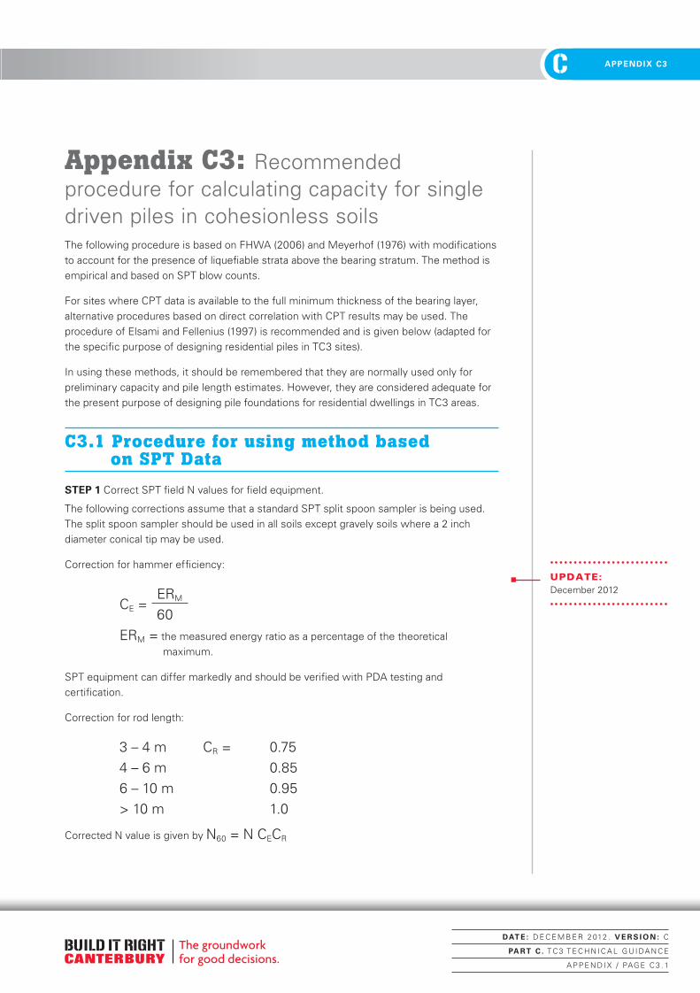
C 2. FOUNDATION ASSESSMENTC APPENDIX C3
Appendix C3: Recommended procedure for calculating capacity for single driven piles in cohesionless soilsThe following procedure is based on FHWA (2006) and Meyerhof (1976) with modifications to account for the presence of liquefiable strata above the bearing stratum. The method is empirical and based on SPT blow counts.
For sites where CPT data is available to the full minimum thickness of the bearing layer, alternative procedures based on direct correlation with CPT results may be used. The procedure of Elsami and Fellenius (1997) is recommended and is given below (adapted for the specific purpose of designing residential piles in TC3 sites).
In using these methods, it should be remembered that they are normally used only for preliminary capacity and pile length estimates. However, they are considered adequate for the present purpose of designing pile foundations for residential dwellings in TC3 areas.
C3.1 Procedure for using method based on SPT Data
STEP 1 Correct SPT field N values for field equipment.
The following corrections assume that a standard SPT split spoon sampler is being used. The split spoon sampler should be used in all soils except gravely soils where a 2 inch diameter conical tip may be used.
Correction for hammer efficiency:
CE = ERM
60ERM = the measured energy ratio as a percentage of the theoretical
maximum.
SPT equipment can differ markedly and should be verified with PDA testing and certification.
Correction for rod length:
3 – 4 m CR = 0.754 – 6 m 0.856 – 10 m 0.95> 10 m 1.0
Corrected N value is given by N60 = N CECR
UPDATE:December 2012
DAT E : D E C E M B E R 2 012 . V E R S I O N : C
PA RT C . T C 3 T E C H N I C A L G U I DA N C E
A P P E N D I X / PAG E C 3 . 1
Canterbury Technical Guidance - PART C.indd 1 22/01/2013 11:19:42 a.m.

C2. FOUNDATION ASSESSMENT CAPPENDIX C3
STEP 2 Compute the average corrected SPT N value, N*, for each soil layer along the embedded length of pile.
STEP 3 Compute unit shaft resistance, fs (KPa) for each soil layer for driven, displacement piles from:
fs (KPa) = 2 N* fs < 200 KPa
for driven, non-displacement piles such as H-piles, use:
fs (KPa) = N* fs < 100 KPa
STEP 4 Compute ultimate shaft resistance, Rsi (KN), for each soil layer i below the lowest liquefiable soil layer.
Rsi = fsi Asi
In which Asi = Pile shaft surface area in layer = (pile perimeter) x (embedded length).
For H-piles in cohesionless soils, the “box” area should generally be used for shaft resistance calculations.
STEP 5 Compute average corrected SPT N values, N*O and N*B, near pile toe.
In most cases, the pile toe will be located within a dense bearing stratum with an overlying stratum of loose and possibly liquefiable soil. N*B is the average corrected N value for the bearing stratum extending 3 diameters below the toe, and N*O is the average corrected N value within the overlying stratum. For cases where the overlying stratum is expected to liquefy, set N*O =0.
STEP 6 Compute unit base resistance, qb (KPa).
For the case of a weaker layer overlying the bearing layer compute qb from:
qb =400N*O +40(N*B – N*O) DbB ≤ 400N*B
in which DB = depth of embedment of toe into bearing layer, and b = pile diameter. For cases where the overlying layer liquefies, set N*O = 0.
For piles driven into non-plastic silts, the unit toe resistance, qb, should be limited to 300 N*B instead of 400 N*B.
STEP 7 Compute ultimate base resistance, Rb (KN).
Rb = qb Ab
In which Ab = Pile base area.
For steel H and unfilled open end pipe piles assume that the pile will plug and use the ‘box’ area of the pile, provided the depth to diameter ratio is greater than 30, otherwise use only the steel cross-section area. qb should be limited to 5000 KPa for open piles.
STEP 8 Compute ultimate pile capacity, after liquefaction, Ruliq (KN).
Ruliq = ∑Rsi + Rb
DAT E : D E C E M B E R 2 012 . V E R S I O N : C
PA RT C . T C 3 T E C H N I C A L G U I DA N C E
A P P E N D I X / PAG E C 3 . 2
Canterbury Technical Guidance - PART C.indd 2 22/01/2013 11:19:42 a.m.
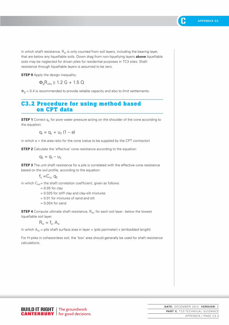
C 2. FOUNDATION ASSESSMENTC APPENDIX C3
in which shaft resistance, Rsi is only counted from soil layers, including the bearing layer, that are below any liquefiable soils. Down drag from non-liquefying layers above liquefiable soils may be neglected for driven piles for residential purposes in TC3 sites. Shaft resistance through liquefiable layers is assumed to be zero.
STEP 9 Apply the design inequality:
ФgRuliq ≥ 1.2 G + 1.5 Q
Фg = 0.4 is recommended to provide reliable capacity and also to limit settlements.
C3.2 Procedure for using method based on CPT data
STEP 1 Correct qc for pore water pressure acting on the shoulder of the cone according to the equation:
qt = qc + u2 (1 – a)
in which a = the area ratio for the cone (value to be supplied by the CPT contractor)
STEP 2 Calculate the ‘effective’ cone resistance according to the equation:
qE = qt – u2
STEP 3 The unit shaft resistance for a pile is correlated with the effective cone resistance based on the soil profile, according to the equation:
fs =Csc qE
in which Csc = the shaft correlation coefficient, given as follows = 0.05 for clay = 0.025 for stiff clay and clay-silt mixtures = 0.01 for mixtures of sand and silt = 0.004 for sand
STEP 4 Compute ultimate shaft resistance, Rsi, for each soil layer i below the lowest liquefiable soil layer.
Rsi = fsi Asi
in which Asi = pile shaft surface area in layer = (pile perimeter) x (embedded length)
For H-piles in cohesionless soil, the ‘box’ area should generally be used for shaft resistance calculations.
DAT E : D E C E M B E R 2 012 . V E R S I O N : C
PA RT C . T C 3 T E C H N I C A L G U I DA N C E
A P P E N D I X / PAG E C 3 . 3
Canterbury Technical Guidance - PART C.indd 3 22/01/2013 11:19:42 a.m.

C2. FOUNDATION ASSESSMENT CAPPENDIX C3
STEP 5 The unit base resistance is computed using a geometric averaging of the effective cone tip resistance over the influence zone at the pile base which, for piles driven into a dense bearing layer, is taken to be a range from 4 pile diameters below the base to 8 pile diameters above the base. The unit base resistance is then given by:
qb =Ctc qEg
in which Ctc is the toe correction coefficient and may be taken as 1.0 for piles less than 400 mm in diameter and qEg is the geometric average of the effective cone tip resistance over the influence zone.
STEP 6 The total pile end bearing resistance is then given by:
Rb =qb Ab
in which Ab = area of the base of the pile.
STEP 7 Compute ultimate pile capacity, after liquefaction, Ruliq (KN).
Ruliq = ∑Rsi + Rb
in which shaft resistance, Rsi is only counted from soil layers, including the bearing layer, which are below any liquefiable soils. Down drag from non-liquefying layers above liquefiable soils may be neglected for driven piles for residential purposes in TC3 sites. Shaft resistance through liquefiable layers is assumed to be zero.
STEP 8 Apply the design inequality:
ФgRuliq ≥ 1.2 G + 1.5 Q
Фg = 0.4 is recommended to provide reliable capacity and also to limit settlements.
DAT E : D E C E M B E R 2 012 . V E R S I O N : C
PA RT C . T C 3 T E C H N I C A L G U I DA N C E
A P P E N D I X / PAG E C 3 . 4
Canterbury Technical Guidance - PART C.indd 4 22/01/2013 11:19:42 a.m.
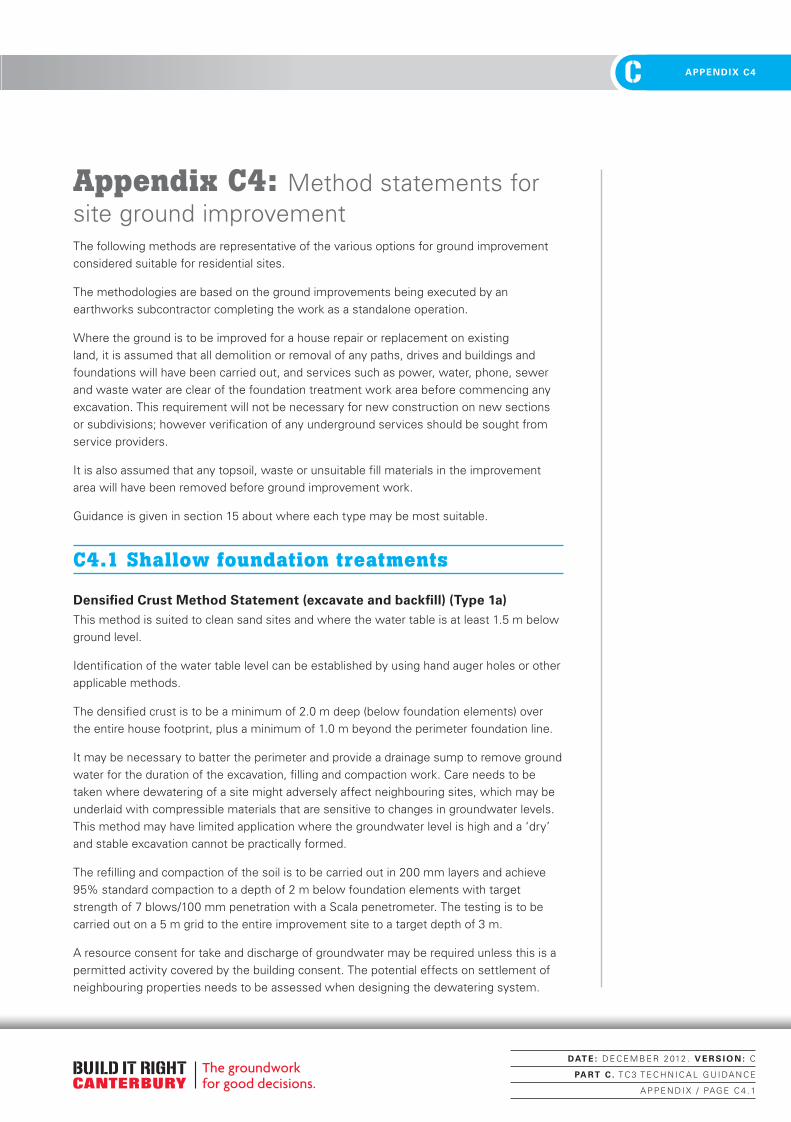
C 2. FOUNDATION ASSESSMENTC APPENDIX C4
Appendix C4: Method statements for site ground improvementThe following methods are representative of the various options for ground improvement considered suitable for residential sites.
The methodologies are based on the ground improvements being executed by an earthworks subcontractor completing the work as a standalone operation.
Where the ground is to be improved for a house repair or replacement on existing land, it is assumed that all demolition or removal of any paths, drives and buildings and foundations will have been carried out, and services such as power, water, phone, sewer and waste water are clear of the foundation treatment work area before commencing any excavation. This requirement will not be necessary for new construction on new sections or subdivisions; however verification of any underground services should be sought from service providers.
It is also assumed that any topsoil, waste or unsuitable fill materials in the improvement area will have been removed before ground improvement work.
Guidance is given in section 15 about where each type may be most suitable.
C4.1 Shallow foundation treatments
Densified Crust Method Statement (excavate and backfill) (Type 1a)This method is suited to clean sand sites and where the water table is at least 1.5 m below ground level.
Identification of the water table level can be established by using hand auger holes or other applicable methods.
The densified crust is to be a minimum of 2.0 m deep (below foundation elements) over the entire house footprint, plus a minimum of 1.0 m beyond the perimeter foundation line.
It may be necessary to batter the perimeter and provide a drainage sump to remove ground water for the duration of the excavation, filling and compaction work. Care needs to be taken where dewatering of a site might adversely affect neighbouring sites, which may be underlaid with compressible materials that are sensitive to changes in groundwater levels. This method may have limited application where the groundwater level is high and a ‘dry’ and stable excavation cannot be practically formed.
The refilling and compaction of the soil is to be carried out in 200 mm layers and achieve 95% standard compaction to a depth of 2 m below foundation elements with target strength of 7 blows/100 mm penetration with a Scala penetrometer. The testing is to be carried out on a 5 m grid to the entire improvement site to a target depth of 3 m.
A resource consent for take and discharge of groundwater may be required unless this is a permitted activity covered by the building consent. The potential effects on settlement of neighbouring properties needs to be assessed when designing the dewatering system.
DAT E : D E C E M B E R 2 012 . V E R S I O N : C
PA RT C . T C 3 T E C H N I C A L G U I DA N C E
A P P E N D I X / PAG E C 4 . 1
Canterbury Technical Guidance - PART C.indd 1 22/01/2013 11:19:43 a.m.

C2. FOUNDATION ASSESSMENT CAPPENDIX C4
Step Type 1a – Activity for Densified Crust (excavate and backfill)
1a.1 Set out perimeter of foundation treatment area and locate marker pegs clear of all workings.
1a.2During excavation any organic material is to be removed from site and reported to the designer.
1a.3Any physical obstructions encountered during excavation shall be reported to the designer for further direction.
1a.4
Excavation in strips or sections of the foundation may be necessary due to site constraints such as adjacent properties or the physical shape of the house. In this case additional care is required at the vertical edge joins by cutting into the previous compacted zone at 2h:1v to ensure compaction integrity is attained across the joins.
1a.5Commence excavation to 2.0 m (below foundation elements) and if water is present construct dewatering sump adjacent to work area. Install pump in the sump and pipe to sediment control.
1a.6 Level and compact the base of the excavation.
1a.7In the event that soft materials are present in the base layer and a suitable level of compaction is not achieved, the engineer will require cement binder to be added and mixed to this first 200 mm subgrade layer.
1a.8Install two layers of tri-axial geogrid (separated by 200 mm of compacted fill material) to the base, sides and allow sufficient to be lapped back 2 m and under the perimeter foundation line at 1 m depth. (Refer sketch of Type 1 Foundation).
1a.9
Fill and compact 200 mm base layer with suitable roller to achieve required density of 95% standard compaction or Scala penetration resistance of 7 blows per 100 mm of DCP or equivalent (eg, Uncorrected SPT N or Dynamic Probe (Heavy) >20 blows/300 mm) . 1 test to each 25 m2 of treatment area.
1a.10Repeat in 200 mm layers, fold back geogrid at 1m depth and continue until original bare ground level is attained.
1a.11Remove dewatering pump and sump once clear of the water table. Back fill and compact as for the foundation treatment work area.
1a.12Import fill to make up for compaction. The fill can be sand or well-graded sandy gravel to be compatible with required final finished layer.
1a.13Provide the designer with records of additional fill, strength and density testing results together with an ‘As-built’ plan.
Densified Crust Method Statement – Dynamic Compaction (DC) (Type 1b)This method is suited to clean sand sites and where the depth to the water table is at least 1 m below ground level. The suitability of a specific site will need to be checked before this method is used.
Dynamic compaction will be best suited to new subdivisions or areas where several repair sites are grouped together. The potential effect of vibrations on neighbours needs to be considered.
The ground improvement is to form a deep densified raft of soil over the house footprint plus at least 2 m outside the perimeter foundation line.
The minimum energy requirement to achieve the target ground improvement is 50 tonne-metres (t-m). This generally achieves densification to 4 m.
DAT E : D E C E M B E R 2 012 . V E R S I O N : C
PA RT C . T C 3 T E C H N I C A L G U I DA N C E
A P P E N D I X / PAG E C 4 . 2
Canterbury Technical Guidance - PART C.indd 2 22/01/2013 11:19:43 a.m.
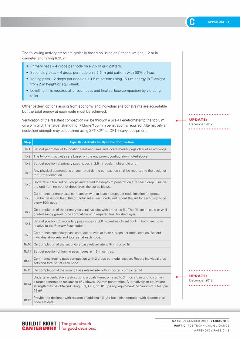
C 2. FOUNDATION ASSESSMENTC APPENDIX C4
The following activity steps are typically based on using an 8 tonne weight, 1.2 m in diameter and falling 6.25 m:
• Primary pass – 4 drops per node on a 2.5 m grid pattern.
• Secondary pass – 4 drops per node on a 2.5 m grid pattern with 50% off-set.
• Ironing pass – 2 drops per node on a 1.5 m pattern using 16 t-m energy (8 T weight from 2 m height or equivalent).
• Levelling fill is required after each pass and final surface compaction by vibrating roller.
Other pattern options arising from economy and individual site constraints are acceptable but the total energy at each node must be achieved.
Verification of the resultant compaction will be through a Scala Penetrometer to the top 3 m on a 5 m grid. The target strength of 7 blows/100 mm penetration is required. Alternatively an equivalent strength may be obtained using SPT, CPT, or DPT (heavy) equipment.
Step Type 1b – Activity for Dynamic Compaction
1b.1 Set out perimeter of foundation treatment area and locate marker pegs clear of all workings.
1b.2 The following activities are based on the equipment configuration noted above.
1b.3 Set out position of primary pass nodes at 2.5 m regular right-angle grid.
1b.4Any physical obstructions encountered during compaction shall be reported to the designer for further direction.
1b.5Undertake a trial set of 8 drops and record the depth of penetration after each drop. Finalise the optimum number of drops from the set vs blows.
1b.6Commence primary pass compaction with at least 4 drops per node location (or greater number based on trial). Record total set at each node and record the set for each drop once every 10th node.
1b.7On completion of the primary pass relevel site with imported fill. The fill can be sand or well graded sandy gravel to be compatible with required final finished layer.
1b.8Set out position of secondary pass nodes at 2.0 m centres off-set 50% in both directions relative to the Primary Pass nodes.
1b.9Commence secondary pass compaction with at least 4 drops per node location. Record individual drop sets and total set at each node.
1b.10 On completion of the secondary pass relevel site with imported fill.
1b.11 Set out position of ironing pass nodes at 1.5 m centres.
1b.12Commence ironing pass compaction with 2 drops per node location. Record individual drop sets and total set at each node.
1b.13 On completion of the Ironing Pass relevel site with imported compacted fill.
1b.14
Undertake verification testing using a Scala Penetrometer) to 3 m on a 5 m grid to confirm a target penetration resistance of 7 blows/100 mm penetration. Alternatively an equivalent strength may be obtained using SPT, CPT, or DPT (heavy) equipment. Minimum of 1 test per 25 m2
1b.15Provide the designer with records of addional fill, ‘As-built’ plan together with records of all node set data.
UPDATE:December 2012
UPDATE:December 2012
DAT E : D E C E M B E R 2 012 . V E R S I O N : C
PA RT C . T C 3 T E C H N I C A L G U I DA N C E
A P P E N D I X / PAG E C 4 . 3
Canterbury Technical Guidance - PART C.indd 3 22/01/2013 11:19:43 a.m.

C2. FOUNDATION ASSESSMENT CAPPENDIX C4
Densified Crust Method Statement – Rapid Impact Compaction (RIC) (Type 1c)This method is suited to clean sand sites and where the depth to water table is at least 1 m below ground level. The suitability of a specific site will need to be checked before this method is used.
Rapid impact compaction will be best suited to new subdivisions or areas where several repair sites are grouped together. The potential effects of vibrations on neighbours need to be considered.
Vibration monitoring should be conducted on adjacent properties. Recommended vibration levels are a Target PPV (Peak particle velocity) < 5 mm/s at the nearest occupied dwelling.
The RIC ground improvement is to form a deep densified raft of soil over the house footprint plus at least 2 m outside the perimeter foundation line.
The minimum energy requirement to achieve the target ground improvement is 8 tonne-metres (t-m). However a higher level may be required (to be determined by testing). The optimum number of blows is to be determined by field trial. The literature suggests a terminal set of 5 mm/blow should be used for control. This generally achieves densification up to 4 m.
The following activity steps are typically based on using a 7.5 tonne weight, 1.5 m in diameter and falling 1.3 m:
• Primary pass – 2.5 m grid pattern – blows continued until 5 mm set/ blow recorded, minimum 12 blows.
• Secondary pass – 2.5 m grid pattern with 50% off-set.
• Levelling fill is required after each pass and final surface compaction by vibrating roller.
Other pattern options arising from economy and individual site constraints are acceptable, but the total energy at each node must be achieved.
Verification of the resultant compaction will be through a Scala Penetrometer to the top 3 m on a 5 m grid. The target strength of 7 blows/100 mm penetration is required. Alternatively an equivalent strength may be obtained using SPT, CPT, or DPT (heavy) equipment.
UPDATE:December 2012
DAT E : D E C E M B E R 2 012 . V E R S I O N : C
PA RT C . T C 3 T E C H N I C A L G U I DA N C E
A P P E N D I X / PAG E C 4 . 4
Canterbury Technical Guidance - PART C.indd 4 22/01/2013 11:19:43 a.m.

C 2. FOUNDATION ASSESSMENTC APPENDIX C4
Step Type 1c – Activity for Rapid Impact Compaction
1c.1 Set out perimeter of foundation treatment area and locate marker pegs clear of all workings.
1c.2 The following activities are based on the equipment configuration noted above.
1c.3 Set out position of primary pass nodes at 2.5 m regular right angle grid.
1c.4Any physical obstructions encountered during compaction shall be reported to the designer for further direction.
1c.5Undertake a trial set of 40 drops and record the depth of penetration (set) after each drop. Finalise the optimum number of drops from the set vs. blows.
1c.6Commence primary pass compaction with at least 12 drops per node location (or greater number based on trial). Record terminal drop and total set at each node.
1c.7On completion of the primary pass relevel site with imported fill. The fill can be sand or well graded sandy gravel to be compatible with required final finished layer.
1c.8Set out position of secondary pass nodes at 2.5 m centres off-set 50% in both directions relative to the primary pass nodes.
1c.9Commence secondary pass compaction with at least 12 drops per node location. Record terminal drop and total sets and total set at each node.
1c.10 On completion of the secondary pass relevel site with imported fill.
1c.11
Undertake verification testing using a Scala Penetrometer to 3 m on a 5 m grid to confirm a target penetration resistance of 7 blows/100 mm penetration. Alternatively an equivalent strength may be obtained using SPT, CPT, or DPT(heavy) equipment. Minimum of 1 test per 25 m2
1c.12Provide the designer with records of additional fill, ‘As-built’ plan together with records of all node set data.
Stabilised Crust Method Statement (excavate, mix and replace) (Type 2a)This method is suited to clean sand sites and where the water table is at least 1.5 m below ground level.
Identification of the water table level can be established by using hand auger holes.
The cement stabilised crust is to be a minimum of 2 m deep (below foundation elements) over the house footprint plus at least 1 m outside the house perimeter foundation line. Depending on the actual mixing method used it may be necessary to batter the perimeter. A drainage sump or well dewatering will be needed to remove ground water where the water table is less than 2 m from the surface.
The cement stabilised crust requires the addition of a minimum of 3%, by weight, of cement added to and mixed with the soil before replacement and light compaction to target the density of natural soils. If the site soil is very silty, the cement content may need to be increased to 5%. The added cement will provide the required increase in strength exceeding 1 MPa at 7 days and initial tangent Young’s Modulus of 400 MPa.
The method may not be used where water inflows cannot be controlled to prepare a dry base to the excavation. Note: A resource consent may be required to take and discharge groundwater unless this is a permitted activity covered by the building consent. The potential effects of settlement to neighbouring properties must be considered.
UPDATE:December 2012
DAT E : D E C E M B E R 2 012 . V E R S I O N : C
PA RT C . T C 3 T E C H N I C A L G U I DA N C E
A P P E N D I X / PAG E C 4 . 5
Canterbury Technical Guidance - PART C.indd 5 22/01/2013 11:19:43 a.m.

C2. FOUNDATION ASSESSMENT CAPPENDIX C4
Step Type 2a – Activity for Stabilised Crust (excavate, mix and replace)
2a.1 Set out perimeter of foundation treatment area and locate marker pegs clear of all workings.
2a.2During excavation any organic material is to be removed from site and reported to the designer.
2a.3Any physical obstructions encountered during excavation shall be reported to the designer for further direction.
2a.4
Excavation in strips or sections of the foundation may be necessary due to site constraints such as adjacent properties or the physical shape of the house. In this case, additional care is required at the vertical edge joins to ensure compaction integrity is attained across the joins, ie, excavate on a batter into the previously treated strip.
2a.5Commence excavation to 2 m below foundation depth and if water is present construct dewatering sump adjacent to work area. Install pump in the sump and pipe to sediment control.
2a.6Excavated material to be passed through a rotary mixer fitted with a weighing device to ensure the cement is added at the optimum rate of 3% by weight. Note the time taken to distribute the cement uniformly throughout the batch and apply to all batches.
2a.7Place cement stabilised soil in base of excavation in 200 mm layers and compact to minimum of 90% standard compaction.
2a.8Remove dewatering pump and sump once clear of the water table. Back fill and compact as for the foundation treatment work area.
2a.9
Test the stabilised soil at a rate of 1 test /100m3 to confirm the target strength at 7 days is achieved. The following criteria may be applied:
• UCS>1 MPa
• Uncorrected SPT>20
• Uncorrected CPT qc>6 MPa
• Scala>10 blows/100 mm
• CBR>25.
2a.10Provide the designer with records of cement dosing rates, density tests on recompacted stabilised soils together with an ‘As-built’ plan.
Note: In ‘Major lateral stretch zones’, two layers of geogrid will also need to be incorporated as previously described for Type 1a – Densified Crust (excavate and backfill).
Stabilised Crust Method Statement (in-place mixing) (Type 2b)This method is suited to most sites where the soils are predominantly sandy.
There are a number of proprietary techniques available for in-place soil mixing. Two known to be locally available are:
a) Tracked-panel stabilisation mixer.
b) Rotary cutter and stabilisation mixer.
Both are coupled to either a grout or dry-cement batching plant. Both are considered suitable for this work if they are operated to produce a homogeneous block of stabilised soil to the required strength.
The stabilised crust should be at least 2 m deep (below foundation elements) over the house footprint, to at least 1.5 m outside the house perimeter foundation line.
UPDATE:December 2012
DAT E : D E C E M B E R 2 012 . V E R S I O N : C
PA RT C . T C 3 T E C H N I C A L G U I DA N C E
A P P E N D I X / PAG E C 4 . 6
Canterbury Technical Guidance - PART C.indd 6 22/01/2013 11:19:43 a.m.

C 2. FOUNDATION ASSESSMENTC APPENDIX C4
Soil is to be uniformly treated with a target dose rate of 5% by weight of cement added to the soil. The cement-stabilised soil is to produce a 7-day target strength exceeding 1 MPa and initial tangent Young’s Modulus of 400 MPa.
Step Type 2b – Activity for Stabilised Crust (in-place mixing)
2b.1 Set out perimeter of foundation treatment area and locate marker pegs clear of all workings.
2b.2 During treatment any organic material encountered is to be reported to the designer.
2b.3Any physical obstructions encountered during treatment shall be reported to the designer for further direction.
2b.4Set out appropriate pattern and sequence to suit equipment type used, ensuring entire area receives a uniform distribution of stabilised mixed soil.
2b.5Commence soil-mixing process and ensure entire treatment area is completed in one continuous operation.
2b.6 As per 2a.9.
2b.7Provide the designer with records of cement-dosing rates, density tests of recompacted stabilised soils together with an ‘As-built’ plan.
C4.2 Deep foundation treatments
Deep Soil Mix (DSM) Columns Method Statement (Type 3)This technique is suited to most sites and, where access can be achieved, is suited to repairs to existing houses.
Soil-mixed columns are constructed using either a jet-grouting rig and grout-batching plant or a rotary auger drilling rig and dry-cement dispenser or grout-batching plant.
The drill has a rotary head fitted with grout jet nozzles to produce a nominal 800 mm diameter column of grout-strengthened soil. The rotary auger rig introduces dry cement or grout at the augers.
Ground improvement is required to the house footprint, and at least 1.5 m beyond the house perimeter foundation line.
800 mm diameter jet-grouting equipment forms columns of 900-1000 mm diameter. When constructed on a 2 m grid or equivalent this achieves 16-20% replacement. The columns should extend to a depth of 8 m below ground level or found in dense sands/gravels proven to be continuous for at least 2 m thickness.
800 mm auger columns will only achieve nominally 840 mm diameter and will require spacing at 1.75 m centres to satisfy the 16-20% replacement.
Cement dosing rate is 10% by weight to achieve target 7-day strength of 2–3 MPa and a stiffness of 400 MPa.
Other diameters may be utilised, but must produce the 16-20% replacement which will require appropriate adjustment to the column spacing. (There will be some constraint on suitable diameters).
UPDATE:December 2012
DAT E : D E C E M B E R 2 012 . V E R S I O N : C
PA RT C . T C 3 T E C H N I C A L G U I DA N C E
A P P E N D I X / PAG E C 4 . 7
Canterbury Technical Guidance - PART C.indd 7 22/01/2013 11:19:43 a.m.

C2. FOUNDATION ASSESSMENT CAPPENDIX C4
Step Type 3 – Activity for Deep Soil Mix (DSM) Columns
3.1 Set out perimeter of foundation treatment area and locate marker pegs clear of all workings.
3.2 During treatment any organic material encountered is to be reported to the designer.
3.3Any physical obstructions encountered during treatment shall be reported to the designer for further direction.
3.4 Set out 2 m grid pattern to the work area.
3.5Commence drilling to first column to verify depth to dense sand – advise designer and confirm depth.
3.6 Complete drilling and soil mixing column process to the entire work area.
3.7Sample the jet grout mix at a rate of 1 cylinder/50 m3 of column for testing to confirm the 7 day properties are achieved.
3.8Provide the designer with records of cement dosing rates, density, strength and stiffness tests together with an “As-built plan.
Stone Columns Method Statement (Type 4)Stone columns are constructed using a drilling rig fitted with either a vibrating or auger probe and follower tube. The follower tube is used to tremie graded aggregate to the tip of the probe during extraction. The probe is also used during extraction for aggregate compaction.
The ground improvement is required to the house floor plan, and at least 2 m beyond the house perimeter foundation line.
800 mm diameter columns are constructed on a 1.75 m grid, down to a depth of 8 m below ground level or to found on dense sand or gravel.
800 mm diameter tremied aggregate on a 1.75 m grid will typically form stone columns that provide 18-20% replacement. Other diameters may be utilised but must produce the 18-20% replacement which will require appropriate adjustment to the column spacing.
DAT E : D E C E M B E R 2 012 . V E R S I O N : C
PA RT C . T C 3 T E C H N I C A L G U I DA N C E
A P P E N D I X / PAG E C 4 . 8
Canterbury Technical Guidance - PART C.indd 8 22/01/2013 11:19:43 a.m.

C 2. FOUNDATION ASSESSMENTC APPENDIX C4
Step Type 4- Activity for Stone Columns
4.1 Set out perimeter of foundation treatment area and locate marker pegs clear of all workings.
4.2 During treatment any organic material encountered is to be reported to the designer.
4.3Any physical obstructions encountered during treatment shall be reported to the designer for further direction.
4.4 Set out 1.75 m grid pattern to the work area.
4.5Commence installing rotary/vibrating probe to first column to verify depth to dense sand – advise designer and confirm depth.
4.6 Complete stone column installations to entire work area.
4.7Undertake CPT, DPT or SPT tests at a rate of 1 test/ 100 m2 at points equidistant between the nearest columns to confirm that the strength of the sand has achieved the required level of improvement as specified below.
4.8 Trim surface and provide 100 mm drainage (aggregate) layer.
4.9Provide the designer with records of aggregate addition quantities, density tests together with an ‘As-built’ plan.
Table C4.1: Soil types for target post-improvement penetration resistance
Silty Soils (Note 1) Silty Sand Soils Sandy Soils
Fines content For use with SPT targets
≥ 35% 15 – 35% < 15%
CPT friction ratio For use with CPT targets
≥ 5% 2 – 5% < 2%
DAT E : D E C E M B E R 2 012 . V E R S I O N : C
PA RT C . T C 3 T E C H N I C A L G U I DA N C E
A P P E N D I X / PAG E C 4 . 9
Canterbury Technical Guidance - PART C.indd 9 22/01/2013 11:19:43 a.m.

C2. FOUNDATION ASSESSMENT CAPPENDIX C4
Figure C4.1: Target post-improvement penetration resistance in soil midway between
stone columns – Scenario 1
If No SPT testing is undertaken within stone columns (or if column SPT results do not meet Scenario 2 targets)
DAT E : D E C E M B E R 2 012 . V E R S I O N : C
PA RT C . T C 3 T E C H N I C A L G U I DA N C E
A P P E N D I X / PAG E C 4 . 10
Canterbury Technical Guidance - PART C.indd 10 22/01/2013 11:19:44 a.m.
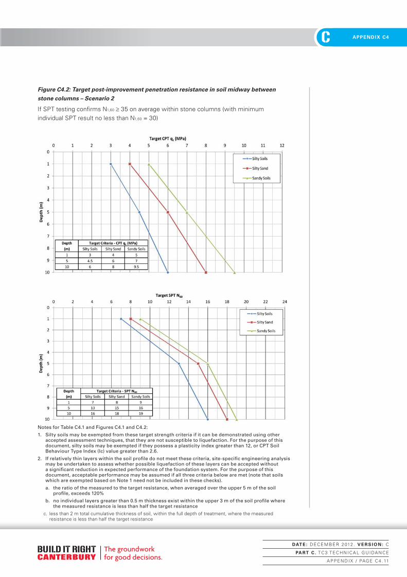
C 2. FOUNDATION ASSESSMENTC APPENDIX C4
Figure C4.2: Target post-improvement penetration resistance in soil midway between
stone columns – Scenario 2
If SPT testing confirms N1,60 ≥ 35 on average within stone columns (with minimum individual SPT result no less than N1,60 = 30)
Notes for Table C4.1 and Figures C4.1 and C4.2:
1. Silty soils may be exempted from these target strength criteria if it can be demonstrated using other accepted assessment techniques, that they are not susceptible to liquefaction. For the purpose of this document, silty soils may be exempted if they possess a plasticity index greater than 12, or CPT Soil Behaviour Type Index (Ic) value greater than 2.6.
2. If relatively thin layers within the soil profile do not meet these criteria, site-specific engineering analysis may be undertaken to assess whether possible liquefaction of these layers can be accepted without a significant reduction in expected performance of the foundation system. For the purpose of this document, acceptable performance may be assumed if all three criteria below are met (note that soils which are exempted based on Note 1 need not be included in these checks).
a. the ratio of the measured to the target resistance, when averaged over the upper 5 m of the soil profile, exceeds 120%
b. no individual layers greater than 0.5 m thickness exist within the upper 3 m of the soil profile where the measured resistance is less than half the target resistance
c. less than 2 m total cumulative thickness of soil, within the full depth of treatment, where the measured resistance is less than half the target resistance
DAT E : D E C E M B E R 2 012 . V E R S I O N : C
PA RT C . T C 3 T E C H N I C A L G U I DA N C E
A P P E N D I X / PAG E C 4 . 11
Canterbury Technical Guidance - PART C.indd 11 22/01/2013 11:19:45 a.m.

C2. FOUNDATION ASSESSMENT CAPPENDIX C4
Low Mobility Grout Columns (LMG) Method Statement (Type 5)This technique is suited to most sites and, where access can be achieved, is suited to repairs to existing houses.
LMG columns are constructed by forming a series of stacked bulbs of pumped grout using a driven casing and grouting rig. Casing driving equipment and a grout batching plant are required and, if the work is undertaken beneath existing concrete structures, coring equipment.
The ground improvement is required to the house footprint plus at least 1.5 m beyond the house perimeter foundation line.
Typically LMG will form bulbs of 800 -1000 mm diameter. (This may not be achievable in fine-grained soils where a minimum of 600 mm should be targeted). When constructed on a 2 m grid or equivalent this achieves 12-15% replacement. The columns should extend to a depth of 8 m or found in dense sands/gravels proven to be continuous for at least 2 m thickness.
The grout should be low slump but pumpable and designed for a minimum 7 day UCS of 15 MPa.
Other diameters may be utilised but must produce the 12-15% replacement which will require appropriate adjustment to the column spacing but should not exceed 3 m.
Step Type 5 – Activity for Low Mobility Grout Columns (LMG)
5.1 Set out perimeter of foundation treatment area and locate marker pegs clear of all workings.
5.2 During treatment any organic material encountered is to be reported to the designer.
5.3Any physical obstructions encountered during treatment shall be reported to the designer for further direction.
5.4 Set out 2 m (or other specified) grid pattern to the work area.
5.5Commence installing casing for first column to verify target depth or depth to dense sand/gravel – advise Designer and confirm depth.
5.6 Complete LMG process to the entire work area. Record the volume of grout used.
5.7Sample the grout mix at a rate of 1 cylinder/50 m3 of column for testing to confirm the 7 day properties are achieved.
5.8Provide the designer with records of cement dosing rates, density, strength and stiffness tests together with an “As-built plan.
DAT E : D E C E M B E R 2 012 . V E R S I O N : C
PA RT C . T C 3 T E C H N I C A L G U I DA N C E
A P P E N D I X / PAG E C 4 . 12
Canterbury Technical Guidance - PART C.indd 12 22/01/2013 11:19:45 a.m.


