1 GEViCAM : A GigE Vision Camera Company GigE Vision Camera GP-Series GP-3360/C (VGA), GP-3780/C (XGA) GP-21400/C (SXGA), GP-151400/C (SXGA) Features • 1Gigabit/s high speed point-to-point transmission • No frame grabber required for image capture • 100m with Gigabit Ethernet cable CAT5e or CAT6 • GigE Vision standard compliant version also available • Field upgradeable firmware via Ethernet • Excellent S/N: >58dB for 12-bit, 10-bit or 8-bit output, 12 to 8-bit Gamma conversion and custom LUT • No-delay asynchronous reset with time stamp and async shutter • GPIO for local I/O, RS-485 communication for auxiliary devices, Audio I/O, Auto-iris lens drive • Color (RGB Bayer) versions available • Miniature, robust package (34 x 34 x 68 mm) • Industrial Ethernet and GPIO connectors • Various drivers available for existing machine vision software • Extensive software developer’s kit (SDK) • Most importantly, low-cost yet high-performance General Description The GEViCAM GP-Series is comprised of Gigabit Ethernet cameras for industrial applications. They are de- signed on a common platform and comply with the GigE Vision standard for plug-and-play performance as well as a proprietary high performance SDK. GP-3360/C uses 1/3” VGA (659 x 494) CCD, GP-3780/C uses 1/3” XGA (1032 x 779) CCD, GP-21400/C uses 1/2” SXGA (1392 x 1040) CCD and GP-151400/C uses 2/3” SXGA (1392 x 1040) with a 12-bit A/D converter. The normal data output is se- lectable for 12-bit, 10-bit (MSB), or 8-bit (MSB) at 40 MHz to maintain excellent S/N ratio of >58 dB at factory default. The frame rate is 100 fps for VGA, 31 fps for XGA, 23 fps for 1/2” SXGA and 22 fps for 2/3” SXGA. For multiple camera applications, it accepts external trig- ger via GPIO (general purpose I/O) and resets the internal timing with no-delay and a time stamp to provide exact im- age locations. This eliminates a need for external sync (HD/VD), which tends to generate some PLL jitter. Streamlined designs for the camera and GigE section re- duce the component count and make these cameras very compact and low cost, yet high performance. This is an ideal opportunity to upgrade machine vision applications from conventional analog cameras (+ frame grabber) to a frame grabber-less systems for improved cost- performance. GigE Vision itself has further advantages over conven- tional systems. It allows multiple camera operations on the net, multicasting (multiple computers per camera), long cable distance (100m without repeaters), auxiliary device control via GPIO, plug-and-play compatibility with com- monly available software and camera systems, common camera control protocol or GUI. The firmware or software is field upgradeable via Ethernet even if the camera is in- stalled in a remote area. The GPIO uses a 14-pin MDR connector and interfaces with TTL (trigger and strobe), RS-485 or CAN, opto- isolated I/Os, and digital audio. A user can download the control protocol for a local auxiliary device such as a PLC or surveillance controls, where the GigE camera then oper- ates as a local server. Auto-iris or DC-iris lens control is available as an option. Audio CODEC is standard for re- mote audio input and output via Ethernet. The platform provides full progressive scan, partial scan, various exposure controls, and other special functions. GigE buffer also allows various sizes of images (Region of interest) to captured and transmitted. GEViCAM World’s Smallest Gigabit Ethernet Camera from GEViCAM also available
Transcript
1 GEViCAM : A GigE Vision Camera Company
GigE Vision Camera GP-Series GP-3360/C (VGA), GP-3780/C (XGA)
GP-21400/C (SXGA), GP-151400/C (SXGA)
Features • 1Gigabit/s high speed point-to-point transmission • No frame grabber required for image capture • 100m with Gigabit Ethernet cable CAT5e or CAT6 • GigE Vision standard compliant version also available • Field upgradeable firmware via Ethernet • Excellent S/N: >58dB for 12-bit, 10-bit or 8-bit output,
12 to 8-bit Gamma conversion and custom LUT • No-delay asynchronous reset with time stamp and
async shutter • GPIO for local I/O, RS-485 communication for auxiliary
devices, Audio I/O, Auto-iris lens drive • Color (RGB Bayer) versions available • Miniature, robust package (34 x 34 x 68 mm) • Industrial Ethernet and GPIO connectors • Various drivers available for existing machine vision
General Description The GEViCAM GP-Series is comprised of Gigabit Ethernet cameras for industrial applications. They are de-signed on a common platform and comply with the GigE Vision standard for plug-and-play performance as well as a proprietary high performance SDK. GP-3360/C uses 1/3” VGA (659 x 494) CCD, GP-3780/C uses 1/3” XGA (1032 x 779) CCD, GP-21400/C uses 1/2” SXGA (1392 x 1040) CCD and GP-151400/C uses 2/3” SXGA (1392 x 1040) with a 12-bit A/D converter. The normal data output is se-lectable for 12-bit, 10-bit (MSB), or 8-bit (MSB) at 40 MHz to maintain excellent S/N ratio of >58 dB at factory default. The frame rate is 100 fps for VGA, 31 fps for XGA, 23 fps for 1/2” SXGA and 22 fps for 2/3” SXGA. For multiple camera applications, it accepts external trig-ger via GPIO (general purpose I/O) and resets the internal timing with no-delay and a time stamp to provide exact im-age locations. This eliminates a need for external sync (HD/VD), which tends to generate some PLL jitter. Streamlined designs for the camera and GigE section re-duce the component count and make these cameras very compact and low cost, yet high performance. This is an ideal opportunity to upgrade machine vision applications
from conventional analog cameras (+ frame grabber) to a frame grabber-less systems for improved cost-performance. GigE Vision itself has further advantages over conven-tional systems. It allows multiple camera operations on the net, multicasting (multiple computers per camera), long cable distance (100m without repeaters), auxiliary device control via GPIO, plug-and-play compatibility with com-monly available software and camera systems, common camera control protocol or GUI. The firmware or software is field upgradeable via Ethernet even if the camera is in-stalled in a remote area. The GPIO uses a 14-pin MDR connector and interfaces with TTL (trigger and strobe), RS-485 or CAN, opto-isolated I/Os, and digital audio. A user can download the control protocol for a local auxiliary device such as a PLC or surveillance controls, where the GigE camera then oper-ates as a local server. Auto-iris or DC-iris lens control is available as an option. Audio CODEC is standard for re-mote audio input and output via Ethernet. The platform provides full progressive scan, partial scan, various exposure controls, and other special functions. GigE buffer also allows various sizes of images (Region of interest) to captured and transmitted.
GEViCAM
World’s Smallest Gigabit Ethernet Camera from
GEViCAM also available
2
GigE Vision Camera GP-Series
Camera Functions and Controls Scan Mode (AquisitionMode): Models VGA XGA SXGA Full Scan Mode: 656 x 494 1032 x 779 1392 x 1040 Partial Scan Mode: 656 x 240 1032 x 400 1392 x 720 Variable (programmable) starting lines available Exposure Control (ExposureMode, ExposureTimeRaw): Variable from 0x0001 to 0xFFFF (decimal 65535) VGA: 20 µs increments from 20 µs (1/50,000 sec) to 1.31 sec XGA/SXGA: 40 µs increments from 40 µs (1/25,000 sec) to 2.62 sec Trigger Functions (TriggerMode): Async No-delay Trigger: Resets internal H and V sync to pixel clock. Exposure is programmable in each mode. Pulse-width Control (ExposureWidth): Resets at external pulse leading edge with no reset delay. The exposure time is exactly the same as the pulse width. Hardware or Software Trigger (TriggerSelector): Trigger type is selectable as PLC (GPIO) function. Hardware is TTL external trigger. Software is initi- ated by PLC and is remotely controlled via Ethernet. Trigger Polarity (TriggerActivation): Start of Falling edge (default) or Rising edge select able. Strobe Functions: Strobe / Exposure Pulse Output: With all async reset modes, the internal exposure pulse is output from a GPIO pin. This can be used to trigger a strobe or other control devices. Back-to-back Strobe: Two consecutive strobes per each trigger can be applied with programmable intervals before and after transfer gate. Thus two frame images at very short intervals can be captured. Good for high speed object motion analysis; dual lighting (i.e. front-lit and back-lit, two color LEDs imaging and other similar applications). This mode is only avail- able in Full Scan Mode. Multiple Frames Capturing with Bracketed Exposure: This is similar to multiple-shot photography with different exposures bracketing the selected exposure condition. This is a great tool for ITS license plate reading, high security identifications, or critical object imaging. Number of frames to be captured is programmable as well as each exposure time: For example; three shots per trigger with 1/250, 1/500, 1/1000s and select the best image among three. Data Output (PixelDepth): Camera image data output is 8-bit as the default. 10-bit, 12-bit (raw data) or 16-bit is also selectable to meet the image processing requirement.
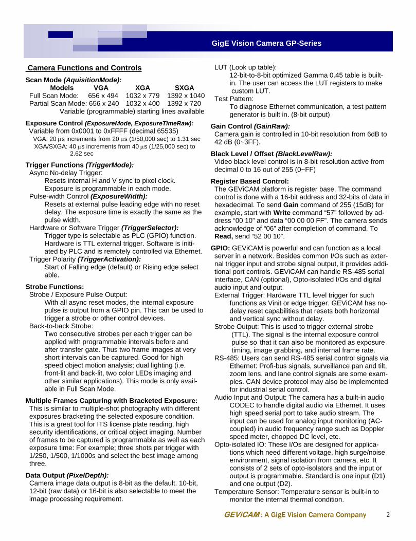
LUT (Look up table): 12-bit-to-8-bit optimized Gamma 0.45 table is built- in. The user can access the LUT registers to make custom LUT. Test Pattern: To diagnose Ethernet communication, a test pattern generator is built in. (8-bit output) Gain Control (GainRaw): Camera gain is controlled in 10-bit resolution from 6dB to 42 dB (0~3FF). Black Level / Offset (BlackLevelRaw): Video black level control is in 8-bit resolution active from decimal 0 to 16 out of 255 (0~FF) Register Based Control: The GEViCAM platform is register base. The command control is done with a 16-bit address and 32-bits of data in hexadecimal. To send Gain command of 255 (15dB) for example, start with Write command “57” followed by ad- dress “00 10” and data “00 00 00 FF”. The camera sends acknowledge of “06” after completion of command. To Read, send “52 00 10”. GPIO: GEViCAM is powerful and can function as a local server in a network. Besides common I/Os such as exter- nal trigger input and strobe signal output, it provides addi- tional port controls. GEViCAM can handle RS-485 serial interface, CAN (optional), Opto-isolated I/Os and digital audio input and output. External Trigger: Hardware TTL level trigger for such functions as Vinit or edge trigger. GEViCAM has no- delay reset capabilities that resets both horizontal and vertical sync without delay. Strobe Output: This is used to trigger external strobe (TTL). The signal is the internal exposure control pulse so that it can also be monitored as exposure timing, image grabbing, and internal frame rate. RS-485: Users can send RS-485 serial control signals via Ethernet: Profi-bus signals, surveillance pan and tilt, zoom lens, and lane control signals are some exam- ples. CAN device protocol may also be implemented for industrial serial control. Audio Input and Output: The camera has a built-in audio CODEC to handle digital audio via Ethernet. It uses high speed serial port to take audio stream. The input can be used for analog input monitoring (AC- coupled) in audio frequency range such as Doppler speed meter, chopped DC level, etc. Opto-isolated IO: These I/Os are designed for applica- tions which need different voltage, high surge/noise environment, signal isolation from camera, etc. It consists of 2 sets of opto-isolators and the input or output is programmable. Standard is one input (D1) and one output (D2). Temperature Sensor: Temperature sensor is built-in to monitor the internal thermal condition.
GEViCAM : A GigE Vision Camera Company
3
GigE Vision Camera GP-Series
Thermal Considerations: Because of high speed transmission, GigE components generate more heat than conventional cameras. The GEVi-CAM series is designed to minimize the power consump-tion, however it gets warm during operation. A heat pipe structure is incorporated to transfer heat from specific com-ponents to the base plate with a very small thermal resis-tance, thus stress to components is minimized for high reli-ability. It is advisable to mount camera to a relatively large heat sink structure (mounting bracket) for demanding appli-cations. Gigabit Ethernet (GigE) Section Ethernet is the most popular and widely used digital com-munication method today. The technology is proven and robust. Gigabit Ethernet is an extension of fast Ethernet but has 1 Gigabit bandwidth, which is a huge benefit for image processing and sending high resolution, high speed digital video to a host. It eliminates the need for a frame grabber in machine vision, thus cost performance improves over conventional [analog camera + frame grabber] or [digital camera (Camera Link) + frame grabber]. There are many benefits to using GigE cameras in a wide variety of applications. • Pleora engine: GEViCAM uses industry-leading Pleora
Technologies’ engine, core and SDK. • High performance driver off-loads CPU tasks. • Deterministic, continuous data transfer occurs at 1Gb/s
for 100m or more with switches. • Versatile SDK supports wide range of applications. Frame Grabber Functions: GigE camera interface functions as a frame grabber. Brief specifications are as follows; On board Memory: 16 MB Programmable Logic Control: 4 Pulse generators and Timers, 1 Rescaler, 1 Delayer, 1 Counter, Input de- bouncing, Timestamp generator, Timestamp trigger, Software controlled I/O, GPIO FIFO and LUT. Serial Ports: Internal UART 3 ports (Normally used for Camera control, RS-485 and Audio I/O) Ethernet Band-width: 1Gb/s Unicast and Multicast: Yes Static Configuration: Yes, 4.01 BOOTP: Yes DHCP: Yes, 4.06 Data Format: Gray scale (8, 10, 12, 14, 16, 24-bit) and Color RGB Bayer Image Size capability: Up to 4K (H) x 4K (V): Horizontal size must be multiple of 4. Other Functions: Windowing, Decimation, Data port map- ping, Pixel shifting, Pixel inversion
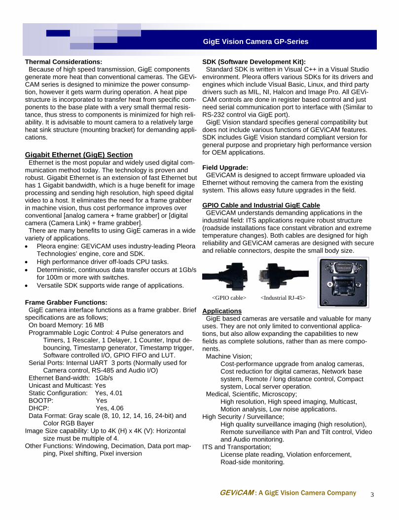
SDK (Software Development Kit): Standard SDK is written in Visual C++ in a Visual Studio environment. Pleora offers various SDKs for its drivers and engines which include Visual Basic, Linux, and third party drivers such as MIL, NI, Halcon and Image Pro. All GEVi-CAM controls are done in register based control and just need serial communication port to interface with (Similar to RS-232 control via GigE port). GigE Vision standard specifies general compatibility but does not include various functions of GEViCAM features. SDK includes GigE Vision standard compliant version for general purpose and proprietary high performance version for OEM applications. Field Upgrade: GEViCAM is designed to accept firmware uploaded via Ethernet without removing the camera from the existing system. This allows easy future upgrades in the field. GPIO Cable and Industrial GigE Cable GEViCAM understands demanding applications in the industrial field: ITS applications require robust structure (roadside installations face constant vibration and extreme temperature changes). Both cables are designed for high reliability and GEViCAM cameras are designed with secure and reliable connectors, despite the small body size.
Applications GigE based cameras are versatile and valuable for many uses. They are not only limited to conventional applica-tions, but also allow expanding the capabilities to new fields as complete solutions, rather than as mere compo-nents. Machine Vision; Cost-performance upgrade from analog cameras, Cost reduction for digital cameras, Network base system, Remote / long distance control, Compact system, Local server operation. Medical, Scientific, Microscopy; High resolution, High speed imaging, Multicast, Motion analysis, Low noise applications. High Security / Surveillance; High quality surveillance imaging (high resolution), Remote surveillance with Pan and Tilt control, Video and Audio monitoring. ITS and Transportation; License plate reading, Violation enforcement, Road-side monitoring.
GPIO Pin Assignment 1 12V RTN (GND) 8 Power in 12V 2 GND 9 Trigger in (TTL) 3 Strobe out 10 RS-485 - 4 RS-485 + 11 Opto D1 in - 5 Opto D1 in + 12 Opto D2 out - 6 Opto D2 out + 13 Audio out 7 GND 14 Audio in
geviD 08-10-20 GEViCAM Inc.
GP-21400UV: UV sensitive CCD GP-21400UV is specifically designed to provide high sensitivity, excellent S/N ratio (>60dB) and UV spectral responses. The characteristics assure excellent applications for semicon-ductor inspection, surface inspection, nanotechnology, scientific field, and medical applications. The camera is designed for the best signal integrity at the highest speed. Since GP-21400UV is sensitive to UV spectrum, the imager features a quartz window so neither a cover glass or an optical filter is installed. Optics work with visual region but if UV region is used, normal glass lens cannot be used. GP-151400: GEViCAM uses the best quality grade of NIR sensitive CCD. GP-151400 is specifically designed to provide high sensitivity, excellent S/N ratio and Near IR spectral responses. The characteristics assures excellent applications for scientific field, high end surveillance, high performance ITS, traffic camera, and medical applications. The camera is designed for the best signal integrity at the highest speed. Therefore, the frame rate is not pushed to 30 fps as it starts exhibiting some degradation of performances. If higher frame rate is required, please contact GEViCAM for the option.
<GP-151400 Spectral Response>
*Product specifications and features are subject to change without notice.
<GP-21400UV Spectral Response>
Wave Length (nm)
Rel
ativ
e Res
pons
e
0.2
0.4
0.6
0.8
1.0
0
673 S. Milpitas Blvd., Milpitas, CA, U.S.A. 95035 Phone: 408-945-9900, Fax: 408-262-0962 1698 Yosemite Drive, Milpitas, CA, U.S.A. 95035 Phone: 408-262-5772, Fax: 408-262-0962


![Arrays in C - Binghamton · Binghamton University CS-220 Spring 2019 Inverted Arrays int vec[5]={365,366,367,368,369}; Label Address Value 0xFFFF FFFC 0xDEAD BEEF 0xFFFF FFF8 0xDEAD](https://static.documents.pub/doc/80x56/5ecbeab3d43cd479d96a082c/arrays-in-c-binghamton-university-cs-220-spring-2019-inverted-arrays-int-vec5365366367368369.jpg)


