PH/No.CTTW Tunnel Washer.doc Page 1 6/24/2008 GIRTON TUNNEL WASHER MODEL CT APPLICATION The Girton Tunnel Washer is a heavy duty, conveyorized, hydrospray washer designed for thorough, efficient cleaning of cages, debris pans, bottles, feeder bowls, and miscellaneous items used in the care of laboratory animals. SIZE (Please circle size desired.) Tunnel Width: 25”, 31”, 37”, “ (other) Tunnel Height: 25”, 31”, “ (other) Overall Machine Length: 15’, 20’, ‘ (other) Conveyor: Belt Width: 24”. 30”, 36”, “ (other) Speed: Variable 2 to 10 feet per minute. FEATURES 1. Removable Spray Headers. The spray headers with machined jets attached, are equipped with quick- disconnect fittings with O-Ring type gaskets for easy removal. Headers, with jet pipes and spray jets attached, may be completely removed, for jet cleaning and maintenance, by hand, without the use of tools of any kind. 2. Flat Wire Conveyor Belt. The conveyor is a stainless steel flat wire 1” x 1” conveyor belt proven for strength, durability, and flexibility. Both ends of the conveyor are equipped with sprockets for reliable belt tracking. Drive system is equipped with a safety overload clutch to protect belt from damaging items being washed. 3. Drawer Type Solution Strainers. The pre-wash, wash, and recirculated rinse solutions are recirculated through stainless steel screens. Screens are easily accessible and have perforations considerably smaller than the machined jet orifices to filter the solutions and prevent jets from clogging. 4. One Piece Construction. Tank, cabinet, and frame are of one-piece welded construction with #2B interior finish. 5. Insulated Construction. The tunnel washer is provided with top, bottom, sides, and ends insulated with 2” thick non-toxic, non-hygroscopic rigid foam insulation covered by a protective 20 gauge stainless steel jacket with #4 exterior finish. OPERATION Items to be cleaned are loaded manually in the inverted position on the conveyor belt at the load end of the tunnel washer. Items are conveyed automatically through the various treatments and discharged at the unload end. TREATMENT SCHEDULE (Typical, consult factory for special treatments.) 1. Pre-Wash. Water recovered from the recirculated rinse tank under pump pressure flushes items to remove gross debris. Spent solution is directed to drain. 2. Wash. Hot detergent solution is recirculated through the jet system under pump pressure. Temperature is adjustable to 190°F. 3. Recirculated Rinse. Hot water is recirculated through the jet system under pump pressure. Temperature is adjustable to 190°F. 4. Final Rinse. Hot water from house supply is sprayed through the jet system. Spent solution drains to recirculated rinse tank. Temperature is adjustable to 195°F. 5. Drying. See separate specification, following. CONSTRUCTION 1. The frame, recirculating tanks, and cabinet are of one-piece welded stainless steel construction. The frame is equipped with adjustable legs, and supports for the pumps, steam heat exchanger, and drive mechanism. 2. Splash proof doors are provided for access to the jet systems and interior of the tunnel washer. Doors are hinged to hold doors in the open and closed positions. Doors are insulated with 2-inch thick rigid foam insulation and are equipped with gutters, bulb sealing gaskets, handles, and heavy-duty hinges. Each door is equipped with a safety switch, to prevent operation whenever any door is in the open position.
Transcript
PH/No.CTTW Tunnel Washer.doc Page 1 6/24/2008
GIRTON TUNNEL WASHER MODEL CT
APPLICATION
The Girton Tunnel Washer is a heavy duty, conveyorized, hydrospray washer designed for thorough, efficient cleaning of cages, debris pans, bottles, feeder bowls, and miscellaneous items used in the care of laboratory animals.
1. Removable Spray Headers. The spray headers with machined jets attached, are equipped with quick-disconnect fittings with O-Ring type gaskets for easy removal. Headers, with jet pipes and spray jets attached, may be completely removed, for jet cleaning and maintenance, by hand, without the use of tools of any kind.
2. Flat Wire Conveyor Belt. The conveyor is a stainless steel flat wire 1” x 1” conveyor belt proven for strength, durability, and flexibility. Both ends of the conveyor are equipped with sprockets for reliable belt tracking. Drive system is equipped with a safety overload clutch to protect belt from damaging items being washed.
3. Drawer Type Solution Strainers. The pre-wash, wash, and recirculated rinse solutions are recirculated through stainless steel screens. Screens are easily accessible and have perforations considerably smaller than the machined jet orifices to filter the solutions and prevent jets from clogging.
4. One Piece Construction. Tank, cabinet, and frame are of one-piece welded construction with #2B interior finish.
5. Insulated Construction. The tunnel washer is provided with top, bottom, sides, and ends insulated with 2” thick non-toxic, non-hygroscopic rigid foam insulation covered by a protective 20 gauge stainless steel jacket with #4 exterior finish.
OPERATION
Items to be cleaned are loaded manually in the inverted position on the conveyor belt at the load end of the tunnel washer. Items are conveyed automatically through the various treatments and discharged at the unload end.
TREATMENT SCHEDULE (Typical, consult factory for special treatments.)
1. Pre-Wash. Water recovered from the recirculated rinse tank under pump pressure flushes items to remove gross debris. Spent solution is directed to drain.
2. Wash. Hot detergent solution is recirculated through the jet system under pump pressure. Temperature is adjustable to 190°F.
3. Recirculated Rinse. Hot water is recirculated through the jet system under pump pressure. Temperature is adjustable to 190°F.
4. Final Rinse. Hot water from house supply is sprayed through the jet system. Spent solution drains to recirculated rinse tank. Temperature is adjustable to 195°F.
5. Drying. See separate specification, following.
CONSTRUCTION
1. The frame, recirculating tanks, and cabinet are of one-piece welded stainless steel construction. The frame is equipped with adjustable legs, and supports for the pumps, steam heat exchanger, and drive mechanism.
2. Splash proof doors are provided for access to the jet systems and interior of the tunnel washer. Doors are hinged to hold doors in the open and closed positions. Doors are insulated with 2-inch thick rigid foam insulation and are equipped with gutters, bulb sealing gaskets, handles, and heavy-duty hinges. Each door is equipped with a safety switch, to prevent operation whenever any door is in the open position.
PH/No.CTTW Tunnel Washer.doc Page 2 6/24/2008
3. Each recirculating tank is equipped with an automatic solution level control, safety overflow piping, manual drain valve, and stainless steel steam coil heating for the recirculating treatment solutions. Automatic digital temperature controllers mounted on the operator’s panel will display and monitor recirculating solution temperatures.
4. The tunnel washer is equipped with stainless steel steam coil heating for the wash and recirculating rinse tanks, complete with condensate return, steam traps, and strainers. Steam coils are removable for cleaning or maintenance.
5. The wash solutions are under pressure from a 5 to 15 Hp pump. The recirculated rinse and pre-wash systems use a 3 to 10 Hp pump. Both pumps are Gusher, or equal, close coupled “Monobloc” type with mechanical seals. Each pump system is equipped with a direct reading pressure gauge.
6. Standard electrical service is 3 phase, 60 cycle, 208/230/460 volts; although any electrical service can be provided. (Please specify voltage available in the washroom.)
7. The electrical control system consists of the following:
a. Control shall be by a commercial, non-proprietary microprocessor, which shall control all sequences and operations. The microprocessor is capable of infinite variation in treatment schedules, self-cleaning cycles, etc., and will be programmed to meet the customer’s specific needs. The cycles are adjustable in both time and function. The controller is housed in a stainless steel enclosure.
b. Within the control box is the microprocessor controller, magnetic starters with overload protection for all motors, transformer for the 1/60/115 volt control circuits, and all other electrical components required for the tunnel washer operation.
c. A printer may be provided for hard copy record-keeping. Printer may be integral with the control panel, or remotely located in a supervisor’s office. (Please consult Girton concerning your preference.)
d. The load and unload ends are equipped with a drive system emergency stop button and warning lights.
8. The jet systems for the pre-wash, wash, and recirculating rinse sections are composed of machined jets fitted into headers. Each header system is equipped with a quick-disconnect fitting with an O-Ring for easy removal when cleaning. Jets are properly sized and the feed lines contain throttle valves to hydraulically hold down light plastic cages and steel pans to the conveyor belt. In addition, jets are strategically placed so water bottles in baskets can be processed through the washer.
9. The final rinse jet system consists of spray headers with machined jets and a balancing valve in the line for optimum water use. The system is equipped with a steam heat exchanger to raise the house hot water supply temperature by approximately 80°F. Heat exchanger is supplied with a temperature gauge and steam throttle valve to adjust the final rinse system temperature.
10. Drive system consists of a 1/2 Hp motor, gear reducer, automatic safety overload clutch, and variable speed drive.
11. Conveyor system includes a stainless steel flat wire mesh belt, sprockets at both drive and idler ends for positive tracking of belt, adjustable take-up bearings on the idler end, and stainless steel guides and supports along entire length.
12. The tunnel washer is provided with a low water cut-off to protect the pump in each recirculating tank. The tunnel washer will cease operations and automatically fill tank to proper level. Status lights will indicate which tank is low. Operations resume automatically when tank is full.
13. The tunnel washer is equipped with stainless steel baffles and rubber curtains between each treatment and at both ends. The curtains are manufactured from 1/8” thick slit neoprene and, with the baffles, minimize the carryover of water.
OPTIONS Please circle features desired.
1. Right Hand or Left Hand Unit. The tunnel washer is designed to meet customer specifications by placing all serviceable components on either the right or left hand side of the tunnel washer.
2. Wall Trim Flange. The tunnel washer is provided with a stainless steel trim flange to seal the opening between the machine and the masonry wall opening.
3. Automatic Self-Cleaning Screen. The discharge of the wash treatment pump is equipped with a stainless steel automatic self-cleaning screen, manufactured from perforated stainless steel with 1/16” diameter perforations. Screen accumulates debris prior to the jet system and is automatically flushed at timed periodic intervals. Fully ported, motor-operated ball valves direct the solution flow to the jet system or the drain.
PH/No.CTTW Tunnel Washer.doc Page 3 6/24/2008
4. Stainless Steel Components. Pumps, valves and all piping and other components that come in contact with recirculating solutions are furnished in stainless steel.
5. Sectionalized Shipment. The tunnel washer is shipped in sections for entry into building. Sections are then welded or bolted together in place on site to eliminate any possibility of leakage.
6. Discharge Conveyor. The tunnel washer is furnished with a 4’ long powered discharge conveyor. This is an extension of the tunnel washer/dryer’s conveyor system.
7. Photoelectric Conveyor Stop. A photoelectric switch is located at the end of the discharge conveyor and will stop the conveyor drive when an item reaches the end of the conveyor. This switch will be deactivated when processing cages through a subsequent bedding dispenser.
8. Temperature Guarantee. The tunnel washer is provided with a temperature guarantee for both recirculating tanks. If the recirculating solution temperature drops below the set temperature, the conveyor belt temporarily stops until the recirculating solution reaches the proper temperature. Status lights will indicate which tank is not at proper temperature.
9. Hold-Down Device. A stainless steel hold-down device shall be supplied to hold light cages and steel pans in proper position for processing. The hold-down shall be adjustable in height and be power operated.
10. Drain Discharge Cooler. The tunnel washer is provided with a cool down cycle integral with the tunnel washer to accept all drain discharges. By mixing with cold water, discharges are cooled to a minimum of 140°F before gravity draining to building drain system. PLEASE NOTE: This option describes a cooler for the recirculating sump drain discharges. It is designed to operate when the drain valve is open. It is not a cooler for the sporadic emissions from the sump's steam heating coil or optional pass-through heat exchanger. These fluids ideally are returned to the steam boiler. If discharging to the drain or sewer is required, and cooling of these fluids is required, we recommend that the cooling device be installed as part of the utility installation.
11. Exhaust. Single point exhaust connection, dampers, exhaust fan, etc. are available. Please consult factory.
12. Chemical Dispenser Ready. Detergent dispenser preparation kit, for use with dispenser provided by others. The dispenser will be controlled by the washer’s microprocessor controller.
13. Water Hammer Arrester. The tunnel washer is equipped with a water hammer arrester to protect customer’s incoming water line from possible damage due to water hammer.
14. Mushroom Switches. Emergency mushroom stop buttons located on both infeed and discharge ends of the tunnel washer system.
15. Low Pressure Steam Controls. Low pressure steam controls for steam pressure of 15 lbs. or lower. (Specify steam pressure available at washer location.)
16. High Pressure Steam Controls. High-pressure steam controls shall be provided for steam pressure of 40 lbs. or higher.
17. Condenser Vent Exhaust. A condenser vent exhaust shall be supplied to remove steam vapor from the exhaust. Used only when a conventional exhaust hook-up cannot be accommodated.
18. Vent Dampers. Manual vent dampers shall be provided for trimming exhaust emissions.
19. Steam Separator. A steam separator shall be interpiped into the tunnel washer to remove suspended water droplets from the incoming steam line, and automatically flush to condensate return. This prevents water “slugging” of the steam supply line.
20. Girton Service Personnel shall supervise the installation of equipment to the owner/contractor.
21. Girton Service Personnel shall return to the jobsite after all utility connections have been made and demonstrate the washer to all operating and maintenance personnel.
22. Complete Installations are available, which may include: a. Disconnect and removal of old washer. b. Set-in-place and assembly of new tunnel washer, by Girton Non-Union Personnel. c. Hook-up to existing utilities, by Girton Non-Union Personnel (All utilities are to be provided within 5’ of the tunnel washer’s utility connections, and with proper disconnects.) d. Start-up, test and demonstration of the new tunnel washer. e. Operator and maintenance personnel training.
PH/No.CTTW Tunnel Washer.doc Page 4 6/24/2008
23. One full year defective parts and replacement labor warranty.
OTHER FEATURES AND OPTIONS ARE AVAILABLE, PLEASE CONSULT FACTORY
MATERIALS – All stainless steel is type 304 unless otherwise noted.
STANDARD ITEMS MATERIAL
1. Frame S/S Structural and Angle 2. Tanks 12 Gauge, S/S, #2B Interior Finish 3. Cabinet 14 Gauge, S/S, #2B Interior Finish 4. Recirculating Pump Piping Stainless Steel 5. Water Piping - Internal Stainless Steel 6. Water Piping - External Stainless Steel 7. Steam Piping - Internal Stainless Steel 8. Steam Piping - External Stainless Steel 9. Condensate Return Piping Stainless Steel 10. Spray Jets Stainless Steel 11. Wash and Rinse Pump Stainless Steel 12. Drain Piping - Internal Stainless Steel 13. Drain Piping - External Stainless Steel 14. Steam Coils Pipe, S/S, Sch. 40 15. Insulation Jacket 18 Gauge, S/S, #4 Finish 16. Barrier Flange 16 - 20 Gauge, S/S, #4 Finish * Please note that all sub components of Girton Washers are non-proprietary and commercially available from various sources, for flexibility and economy of maintenance throughout the life of the washer.
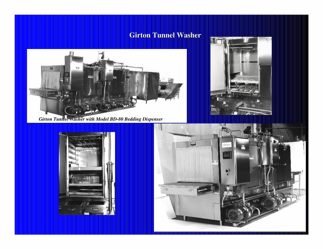
Girton Tunnel Washer with Model BDGirton Tunnel Washer with Model BD--80 Bedding Dispenser80 Bedding Dispenser