129
Glass Balustrades Competent Person(Glazing)
| Date post: | 20-Feb-2017 |
| Category: |
Engineering |
| Upload: | nick-wright |
| View: | 426 times |
| Download: | 1 times |

Glass Balustrades
Competent Person(Glazing)

Glass Balustrades1. Legal Framework
2. Design Guidelines
3. Balustrade Components
4. Calculation and Testing

Glass Balustrades1.Legal Framework2. Design Guidelines
3. Balustrade Components
4. Calculation and Testing

Regulation - PART B - STRUCTURAL DESIGN
B1 DESIGN REQUIREMENT(1) Any building and any structural element or component thereof shall be designed to provide strength, stability, serviceability and durability under all actions which can reasonably be expected to occur in accordance with accepted principles of structural design, and so that it will not impair the integrity of any other building or property.(2) Any such building shall be so designed that in the event of accidental overloading the structural system will not suffer disastrous or progressive collapse which is disproportionate to the original cause.(3) The requirements of sub-regulations (1) and (2) shall be deemed to be satisfied where such building is designed in accordance with SANS 10400-B.

4.2.1.2 The representative permanent, imposed and seismic loads and impact sources applied to the structure and structural elements shall be in accordance with the requirements of SANS 10160.
SANS 10400 The application of the National Building Regulations
Part B: Structural design4.2.1.1 The design working life of a building other than a category 1 building shall be not less than 30 years in respect of the structural system and non-accessible components, and 15 years for repairable or replaceable components and materials, such as claddings, roofing materials, exterior trims, and integrated components, such as windows and doors.

Regulation - PART D - PUBLIC SAFETYD1 CHANGE IN LEVELThe protection of the edge of any balcony, bridge, flat roof orsimilar place shall be designed to prevent any person from falling from such balcony, bridge, flat roof or similar place.

4.2 Change in level 4.2.1 Any balustrade or wall provided to protect a change in level shall comply with the requirements of SANS 10400-B.
The application of the National Building RegulationsPart D: Public safety
4.2.2 The edge of any balcony, bridge, flat roof or similar place more than 1 m above the adjacent ground or floor level shall be provided with a balustrade or parapet wall not less than 1 m in height, unless unauthorized access of persons thereto has been excluded by a physical barrier properly erected and maintained.4.2.3 In the case of an interior balcony or a mezzanine floor, such balcony or floor shall be provided with a balustrade or wall not less than 1 m in height, provided that where such balcony or floor is used for public seating in rows such height may be reduced to not less than 800 mm opposite the seating in the front row.4.2.4 A balustrade or wall provided as protection at a change in level in any occupancy classified as E2, E3, E4, H1, H2, H3, H4 or H5 shall not have any opening that permits the passage of a 100 mm diameter ball, provided that such protection in any occupancy that is not an occupancy classified as E2, E3, E4, H1, H2, H3, H4 or H5, shall consist of at least a handrail and one other rail midway between such handrail and the floor.


PART N - GLAZINGN1 TYPE AND FIXING OF GLAZING
(1) Any material used in the glazing of any building shall be of a secure and durable type and shall be fixed in an manner and position that will ensure that it will -(a) safely sustain any wind actions which can reasonably be expected;(b) not allow penetration of water to the interior of the building; and(c) be apparent, in the case of clear glazing, to any person approaching such glazing.
(2) Glass, plastics and organic coated glass shall be selected in order to provide, in the case of human impact, a degree of safety appropriate in relation to -(a) the position of the glazed area; and(b) the number and likely behaviour pattern of persons expected to be in close proximity to such glazed area.
(3) The requirements of sub-regulations (1) and (2) shall be deemed to be satisfied where the glazing material is selected, fixed and marked in accordance with SANS 10400-N.

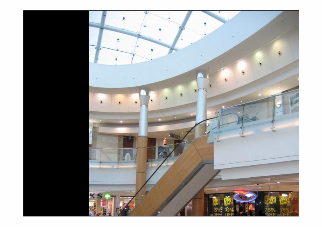
SANS 10400 Part N 4.4.2 Safety glazing materials that comply with SANS 1263-1 shall be used where...glazing is used in any wall or balustrade to (or immediately adjacent to) a stairway, ramp, landing, pathway, patio, veranda or balcony;
SANS 10400 Part N 4.4.2 Safety glazing materials that comply with SANS 1263-1 shall be used where...glazing is used in any wall or balustrade to (or immediately adjacent to) a stairway, ramp, landing, pathway, patio, veranda or balcony;

SANS 10400 Part N 4.4.2 Safety glazing materials that comply with SANS 1263-1 shall be used where...glazing is used in any wall or balustrade to (or immediately adjacent to) a stairway, ramp, landing, pathway, patio, veranda or balcony;

Glass Balustrades1. Legal Framework
2.Design Guidelines3. Balustrade Components
4. Calculation and Testing


4.2 General pre-requisitesThe general pre-requisites for the application of SANS10160 are as follows:a) the choice of the structural system and the design of the structure shall be made by a competent person;b) execution shall be carried out by personnel having the appropriate skills and experience;c) adequate supervision and quality control shall be provided during the execution of the work, namely, in the design offices, factories, plants, and on site;d) the construction materials and products shall be in accordance with the appropriate materials based structural design standards (see 4.1).e) the structure shall be adequately maintained; andf) the structure shall be used in accordance with the design assumptions.

5.3 Ultimate limit states5.3.1 Ultimate limit states relate to the following:a) the safety of people; andb) the safety of the structure.
5.4 Serviceability limit states5.4.1 Serviceability limit states apply to the following requirements for the structure under normal use:a) the functioning of the structure or structural members;b) the acceptability of the structure by users in terms of perceived safety and wellbeing; (for example deflection) andc) the appearance of the structure. (for example distortion)
3.1.24serviceability limit statesstates that correspond to conditions beyond which specified service requirements for a structure or structural member are no longer met3.1.26ultimate limit statestate associated with collapse or with other similar forms of structural failure


9 Imposed loads on buildings9.1 Actions9.1.1 Imposed loads on buildings arise from occupancies such asa) normal use by persons,(impact loads, point loads on floors and roofs)b) furniture and movable objects (for example, moveable partitions, storage or the contents of containers),c) vehicles,d) anticipated rare events, such as concentrations of persons or of furniture, (line loads on balustrades)e) the moving or stacking of objects which may occur during reorganisation or redecoration, andf) storage and industrial use.9.1.2 Imposed loads are modelled by uniformly distributed loads (wind load and self weight), line loads or concentrated loads or combinations of these loads.9.1.3 For the determination of imposed loads, the floor and roof areas of the building shall be subdivided into categories according to their use.9.1.4 Heavy equipment (for example, in communal kitchens, radiology rooms or boiler rooms) is not covered in this part of SANS 10160 and the appropriate floor loads shall be established in accordance with the principles given in SANS 10160-1.

Glass Balustrades1. Legal Framework
2. Design Guidelines
3.Balustrade Components4. Calculation and Testing

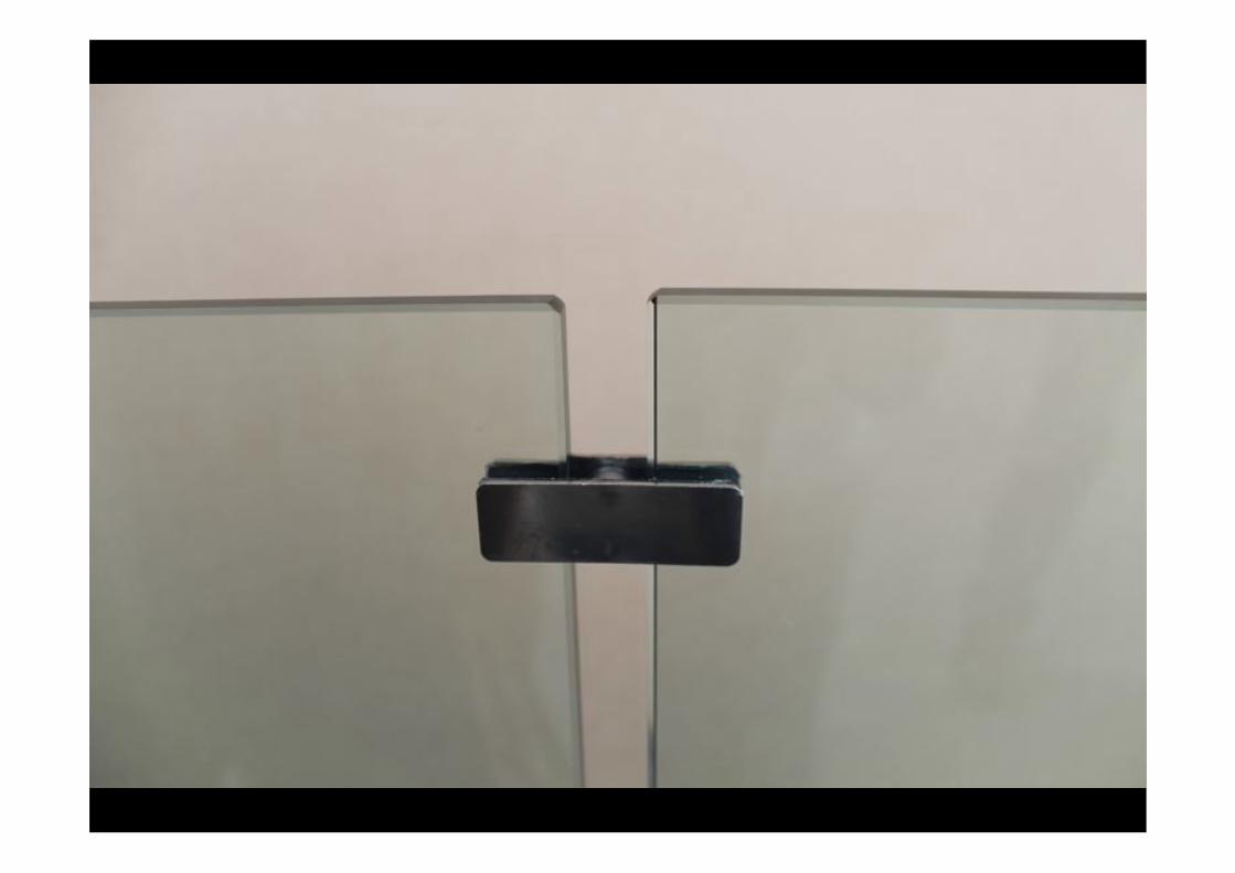
Balustrade Components• Glass
• Edges and Holes
• Surface (sandblasting)
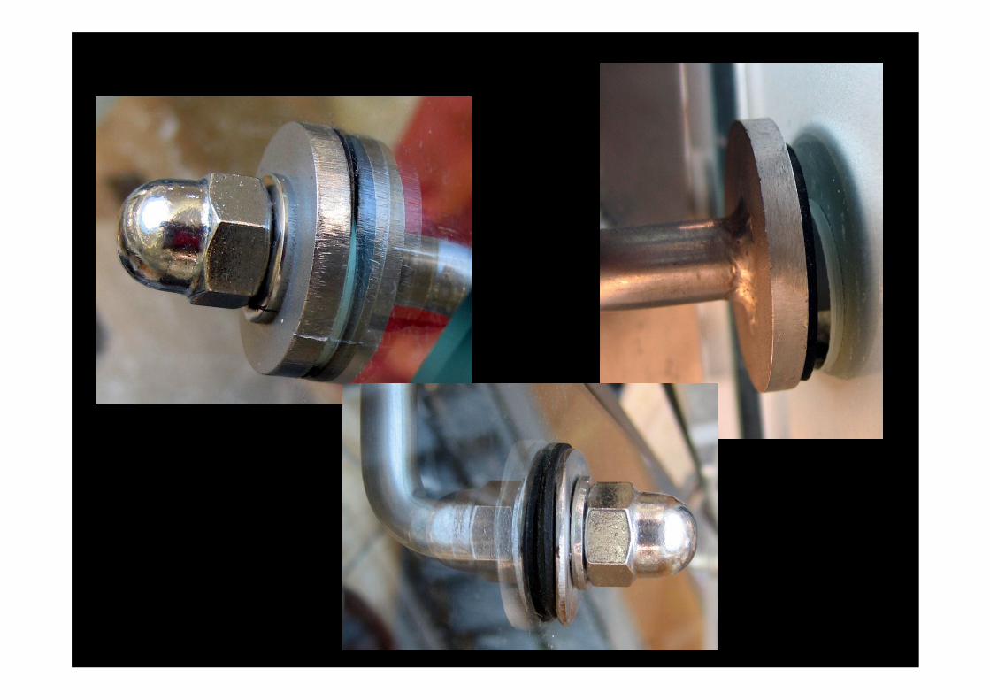
• Bolts
• Washers
• Gaskets
• Fixings
• Etc


Glass Balustrades1. Legal Framework
2. Design Guidelines
3. Balustrade Components
4.Calculation and Testing

SANS 10400 Part N 4.4.4 Glass in balustrades shall be toughened safety glass unless rigidly supported on all sides.Glazing material in balustrades is subject to the impact and line loads determined in accordance with the requirements of SANS 10160-2.

9.4 Horizontal loads on parapets, partition walls and guardrails acting as barriers
9.4.1 The characteristic values of loads on parapets, railings, balustrades and walls acting as barriers, including partition walls, exterior walls, curtain walls and glazing units are specified in 9.4.
9.4.2 The characteristic values of the line load, qk,, acting at the height of the partition wall or parapets but not higher than 1,20 m, shall be taken from table 7.
9.4.3 The characteristic loads, qk and Qk, shall not be applied simultaneously.


1kN/100mm
0.5/ 1.5/ 3.0 kN/metre
1kN / 100x100mm
Line Load and Point Load
1 metre

Line Load and Point Load Balustrade with Posts
1kN/100m
m
0.5/ 1.5/ 3.0 kN/metre
1kN / 100x100mm
1 metre
Line Load taken by Posts – Calcs by Engineer.Point Load Use Roark

Line Load and Point Load Balustrade with Posts
1kN/100m
m
0.5/ 1.5/ 3.0 kN/metre
1kN / 100x100mm
1 metre
Point Load Use Roark
Use factor for point support!
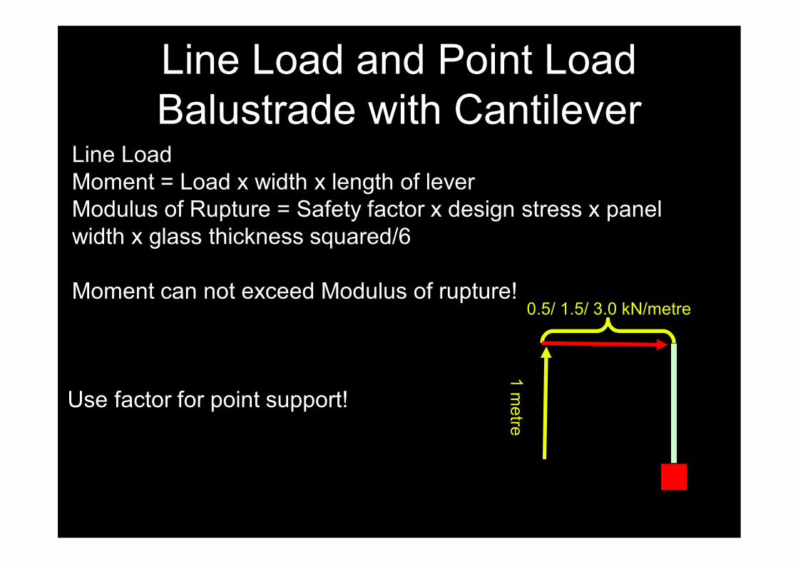
Line Load and Point Load Balustrade with Cantilever
0.5/ 1.5/ 3.0 kN/metre1 m
etre
Line LoadMoment = Load x width x length of leverModulus of Rupture = Safety factor x design stress x panel width x glass thickness squared/6
Moment can not exceed Modulus of rupture!
Use factor for point support!

Line Load and Point Load Balustrade with Cantilever
0.5/ 1.5/ 3.0 kN/metre1 m
etre
Line Load
Design stress = 50MPaGlass thickness from SANS 50572
Use safety factor for point support!

Line Load and Point Load Balustrade with Cantilever
1.0 kN1 m
etre
Point LoadIf there is a hand rail point load is spread between panels.If there is no hand rail narrow panels are really bad!
Use safety factor for point support!

Line Load and Point Load Balustrade with Cantilever
1.0 kN
1 metre
Cantilever Indicative Toughened Glass Thickness
Line Load
Channel Surface Mount
Face Mount bolted
0.5 12 21.52
1.5 15 25.52
3 21.52 31.52

Line Load and Point Load Balustrade with Cantilever
1.3 x 1.0 kN1 m
etre
Or Test!
Use safety factor of 30 % over load


Load Duration Factors adapted from ASTM E1300-02
Duration Factor3 s 1.0010 s 0.931 min 0.8310 min 0.7260 min 0.6412 h 0.5524 h 0.531 week 0.471 month 0.431 year 0.36Beyond 1 year 0.31


9.4.6 Ensure that all walls, curtain walls, partitions, balustrades and all large glazed areas within one metre of the floor that may be exposed to impact from a person falling against or bumping into them, have a level of impact resistance which will prevent undue risk of injury including the prevention of the person from falling through a balustrade, resulting from failure, fracture or penetration of the wall, partition, curtain wall, glazed panel or balustrade.
Impact Testing• No calculations!• Use experience with caution!


9.4.7 Resistance to impact will be proven by testing using an impact of 400 J delivered by means of a 250 mm diameter bag filled with dry sand to a mass of 30 kg, representative of the most severe conditions likely to occur. The impact test may be reduced to 200 J for instances where the perpendicular approach distance is less than 1,5 m.
NOTE 1 See SANS 1263-1 for an impactor capable of greater uniformity of impact and of delivering impacts up to and exceeding 400 J.NOTE 2 For non-brittle materials and for masonry, the ability to withstand the forces specified in 9.4 with the normal resistance factors for the materials concerned will generally ensure adequate resistance to human impact.NOTE 3 The approach distance limits the velocity and therefore the impact energy of a person and this is reduced where approach distances are small, such as on narrow staircases or corridors. If a door is positioned opposite such a barrier then the approach distance will increase, and if this exceeds 1,5 m then the higher impact energy of 400 Jshould be used. If non-load bearing systems such as dry wall partitions are installed and conceivably the position of doors or openings adjacent to the barrier change and affect the approach distance, then the higher impact energy of 400 J should be used.NOTE 4 It is recommended that the installation be verified in its final position to ensure that connections to support work and levels of onsite workmanship allow the design to meet impact performance requirements.

Approach Distance


SANS 10137• Figure 16: Principles of a toughened glass
infill panel bolted connection

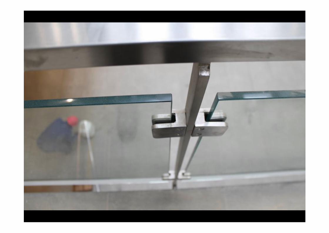
SANS 10137• Base fixing of free standing glass barriers –
Localized fixing clamp
Fixing clamps not less than 100mm x 150mm x 12mm thick steel. Two fixing clamps for every 1000mm length of barrierA = minimum 2 x glass thickness from edge of glass to edge of holeGlass hole diameter = bolt diameter + 10mm

SANS 10137• Base fixing of free standing glass barriers –
Continuous fixing clamp
Fixing clamps not less than 100mm wide x 12mm thick steel. Maximum bolt spacing 500mmA = minimum 2 x glass thickness from edge of glass to edge of holeGlass hole diameter = bolt diameter + 10mm

SANS 10137• Base fixing of free standing glass barriers –
Continuous fixing clamp
Fixing clamps not less than 100mm wide x 12mm thick steel. Maximum bolt spacing 500mmA = minimum 2 x glass thickness from edge of glass to edge of holeGlass hole diameter = bolt diameter + 10mm

Glass Balustrades1. Each Installation Needs a Sign Off
2. Design Loads Critical
3. Balustrade Components must be correcrt
4. Calculation and Testing MUST be completed.
5. The Magistrate Defence!


