32
LIQUID LEVEL GAGES & VALVES
| Date post: | 23-Mar-2018 |
| Category: |
Documents |
| Upload: | trinhthien |
| View: | 215 times |
| Download: | 2 times |

mechanical stress or accident rather than
be considered. Four basic precautions when
1. Proper glass selection
2. Correct installation.
3. Periodic inspection and cleaning.
4. Replacement as necessary.
Proper glass selection involves size, pressure
should be crystal clear and without blemish;
results in breakage, a multiple-section gage with shorter glasses should be considered.
Installation involves proper seating on gaskets and cushions; glass-to-metal contact should not occur; do not install any glass with scratches or chipped
edges; do not tighten gage bolts when gage is in use; use torque instructions provided with gage;
vessel center-to-centers are correct and vertical.
extremely important, so that no unusual stress is introduced into the glass.
scratches, chipped edges on glass; inspect glass
and cushions should be automatically replaced to reduce risk; make sure gage or tubular valves
en than similar glasses used in low temperature services.
CAUTION
GLASS-TRAC GAGE ASSEMBLY(Nummbers Indiccate Proper BBolt Torquuing Sequeence.)
GUAGE SERIES TORQUE (TIGHTEN IN 4 – 5 FT-LB. STEPS)
.bL-.tF 02rebmahC egraL erusserP woL
.bL-.tF 23erusserP-diM
.bL-.tF 04erusserP-hgiH
13960 S. Wayside, Houston, Texas 77048Toll Free: 866.240.9906 | Tel: 281.240.0440 | Fax: [email protected]
WWW.QTSLEVEL.COM000-00 06/17
ASME Sec. VIII Div I BPVC ASME “S” & “R”
Stamp holder
ISO 9001: 2008
Registered
CNC Precision
components
LIQUID LEVEL GAGES & VALVES
QTS_LiquidLevelGagesValves_20170627.indd Spread 1 of 2 - Pages(4, 1) 6/27/17 10:24 AM

er: Questtec Solutions is a young company with
the liquid level gage and valve product lines
measurement companies, Daniel Measurement and Control, directed this product development and engineering.
September 27, 2001, the Daniel liquid level gage and valve product lines were purchased by Questtec Solutions at Questtec have
Questtec relocated
erings such as Magnetic Level gages, High Pressure Steam gages and Electronic Boiler trim.
When choosing your liquid level measurement solution provider, why not choose
Questtec to be best suited to assist you solve your liquid level measurement challenges.
QUESTTEC SOLUTIONS
LIQUID LEVEL GAUGES & VALVES
88
88
SIZE NO. MINIMUM CENTER-TO-CENTER TANK CONNECTIONS
OFFSET VALVE HANDLES OFFSET VALVE HANDLES
11
21
31
41
51
61
71
81
91
32
42
52
62
72
82
92
63
73
83
93
74
84
94
75
85
95
86
96
87
97
88
98
89
99
INSTALLATION: CLOSE HOOK-UP GAGES(GAGE CONNECTIONS)
STRAIGHT-THRU VALVE
CLOSE HOOK-UP WITH HANDLE INSIDE
CLOSE HOOK-UP WITH HANDLE OUTSIDE
QUESTTEC SOLUTIONS
LIQUID LEVEL GAUGES & VALVES
QUEST-TEC SOLUTIONS | PAGE 3
QTS_LiquidLevelGagesValves_20170627.indd Spread 2 of 2 - Pages(2, 3) 6/27/17 10:24 AM

GLASS-TRAC LIQUID LEVEL GAGES and VALVES
ORDERING INFORMATION Please Specify:
· Gage Size Number · Type of Service · Temperature Limits · Pressure Limits · Type of Connections · Special Functions · Vessel Centers if Close Hook-up
GAGE NUMBERING SYSTEM Example: 71-RL: 7 is #7 Glass (#1 through #9) 1 is One-Section Gage (1, 2, 3, 4, . . .) R is Reflex (T-Transparent) L is Low Pressure Series (M = Mid, H = High, WP = Weld Pad) (Add appropriate digits or letters to indicate special purpose gage or accessory) HC Externally Heating/Cooling Gages FP Frost Preventive Extensions LC Large Chamber Gage EP Explosion Proof Illuminator CH Close Hook-up Connections
CONTENTS
REFLEX GAGES With Straight-Thru Connections . . . . . . . . . . . . . . . . . . . .2 With Close Hook-up Connections . . . . . . . . . . . . . . . . . .2 Pressure Ratings and Dimensions . . . . . . . . . . . . . . . . 3-4 TRANSPARENT GAGES With Straight-Thru Conections . . . . . . . . . . . . . . . . . . . . .5 With Close Hook-up Connections . . . . . . . . . . . . . . . . . . . 5 Pressure Ratings and Dimensions . . . . . . . . . . . . . . . . .6-7 OFFSET VALVES Type 1S and 1U . . . . . . . . . . . . . . . . . . . . . . . . . . . . . . .8 Type 2S and 2U . . . . . . . . . . . . . . . . . . . . . . . . . . . . . . .8 Type 3S and 3U (OS&Y) . . . . . . . . . . . . . . . . . . . . . . . . 9 Type 7S and 7U (OS&Y) . . . . . . . . . . . . . . . . . . . . . . . . 10 STRAIGHT-THRU VALVES Type 4S and 4U . . . . . . . . . . . . . . . . . . . . . . . . . . . . . .11 Type 5S and 5U (OS&Y) . . . . . . . . . . . . . . . . . . . . . . . .12 TUBULAR GAGES AND VALVES Gages . . . . . . . . . . . . . . . . . . . . . . . . . . . . . . . . . . . . .13 Tubular Valves (Brass) . . . . . . . . . . . . . . . . . . . . . . . . . 14 Tubular Valves (Type 1T and 2T) . . . . . . . . . . . . . . . . . .15 SPECIALTY GAGES Welding Pad Gages . . . . . . . . . . . . . . . . . . . . . . . . . . . .16 Large Chamber for Viscous Liquids . . . . . . . . . . . . . . 17-18 Heated/Cooled Externally . . . . . . . . . . . . . . . . . . . . .19-20 Frost-Prevention Extension . . . . . . . . . . . . . . . . . . . .21-22 Illuminators (Explosion-Proof) . . . . . . . . . . . . . . . . . . . . 23 Quick-Opening Levers . . . . . . . . . . . . . . . . . . . . . . . . . .24 DIMENSIONAL DATA Flat Gage Glasses . . . . . . . . . . . . . . . . . . . . . . . . . . . . .24 Gage Connections . . . . . . . . . . . . . . . . . . . . . . . . . . . . .25 Tank Connections . . . . . . . . . . . . . . . . . . . . . . . . . . .26-27 Installation: Standard Gages . . . . . . . . . . . . . . . . . . . . 28 Installation: Close Hook-up . . . . . . . . . . . . . . . . . . . . . 29
Carbon steel is the standard material for all Glass-Trac low, mid and high pressure liquid level gages. The percentages of carbon steel pressure ratings for optional gage materials are listed below. GAGES GASKETS Stainless Steel 300 & 400 Types . . . . . . . . . 100% Special Acid Sheet Gasketing . . . . . . . . . . . . . . 75% Monel, Hastelloy B & C . . . . . . . . . . . . . . . . . 90% Teflon®, KEL-F® . . . . . . . . . . . . . . . . . . . . . . . . 50% Brass . . . . . . . . . . . . . . . . . . . . . . . . . . . . . . . 50% Glass Filled Teflon . . . . . . . . . . . . . . . . . . . . . . 100%
Teflon is a registered trademark of DuPont. All specification are subject to change without notice as part of a continuing program of product improvement. KEL-F Is a registered trademark of 3M.

REFLEX GAGES Glass-Trac Reflex Gages use prism glass to provide an excellent indication of the liquid level. All liquids appear black in high contrast to the mirror-like surface above. This clean line of separation can be sighted from many yards away. Reflex Gages are made in three pressures series (maximum 4000 psig @ 100ºF) and are tapped for ½” or ¾” NPT connections. The standard Glass-Trac level gages are designed for minimum -20ºF service. On Glass-Trac Reflex Close Hook-up Gages with ½” NPT connections, the center-to-center dimensions is the same as the overall length on standard gages. On Close Hook-up Gages with ¾” NPT connections, the center-to-center dimensions is the same as the overall length on standard gages plus ⅜”.
MATERIALS BODY (LIQUID CHAMBER): Accurately machined from square tubes to provide perfect seating for gage glasses. Glass is recessed for protection. Body materials include 316 stainless steel and carbon steel. COVER: Glass-Trac gage covers are made of carbon steel or 316 stainless steel in all their sizes and pressure ratings for higher strength and dependable service. All covers are machined to provide recessed seating protection for the glass. GLASS: All standard Glass-Trac Reflex Gages use tempered borosilicate glass in nine standard lengths. Each glass has expertly molded reflecting prisms. GASKETS & CUSHONS: High grade non-asbestos is used in gaskets and cushions for Glass-Trac gages. The machined recess in the gage body and cover protects the gasket and cushion as well as the glass. BOLTS: Glass-Trac gage bolts are made of alloy steel, ASTM A-193 Grade B7. NUTS: Gage nuts are made of steel, ASTM A-194 Grade 2H. (Torque instructions for gage bolts are on the back cover.)
TYPICAL REFLEX TOP/BOTTOM
TYPICAL-REFLEX CLOSE HOOK-UP
2

*3/4” NPT Tapped High Pressure Gages Add “1 ½” to ‘A’ Dimension.
3
11 RL 11 RM 11 RH 5 1/4 8 7/8 9 1/4 3 3/4 3 3/4 5 1/4 5 5/8 7 821 RL 21 RM 21 RH 6 1/4 9 7/8 10 1/4 4 3/4 4 3/4 6 1/4 6 5/8 8 931 RL 31 RM 31 RH 7 1/4 10 7/8 11 1/4 5 3/4 5 3/4 7 1/4 7 5/8 9 1141 RL 41 RM 41 RH 8 1/4 11 7/8 12 1/4 6 3/4 6 3/4 8 1/4 8 5/8 10 1251 RL 51 RM 51 RH 9 3/8 13 13 3/8 7 7/8 7 7/8 9 3/8 9 3/4 12 1461 RL 61 RM 61 RH 10 5/8 14 1/4 14 5/8 9 1/8 9 1/8 10 5/8 11 14 1671 RL 71 RM 71 RH 11 3/4 15 3/8 15 3/4 10 1/4 10 1/4 11 3/4 12 1/8 15 1881 RL 81 RM 81 RH 13 3/8 17 17 3/8 11 7/8 11 7/8 13 3/8 13 3/4 17 2091 RL 91 RM 91 RH 14 1/8 17 3/4 18 1/8 12 5/8 12 5/8 14 1/8 14 1/2 18 21
32 RL 32 RM 32 RH 14 1/2 18 1/8 18 1/2 13 5 3/4 14 1/2 14 7/8 19 2242 RL 42 RM 42 RH 16 1/2 20 1/8 20 1/2 15 6 3/4 16 1/2 16 7/8 22 2552 RL 52 RM 52 RH 18 3/4 22 3/8 22 3/4 17 1/4 7 7/8 18 3/4 19 1/8 24 2862 RL 62 RM 62 RH 21 1/4 24 7/8 25 1/4 19 3/4 9 1/8 21 1/4 21 5/8 27 3272 RL 72 RM 72 RH 23 1/2 27 1/4 27 1/2 22 10 1/4 23 1/2 23 7/8 29 3582 RL 82 RM 82 RH 26 3/4 30 3/8 30 3/4 25 1/4 11 7/8 26 3/4 27 1/8 34 4092 RL 92 RM 92 RH 28 1/4 31 7/8 32 1/4 26 3/4 12 5/8 28 1/4 28 5/8 37 43
63 RL 63 RM 63 RH 31 7/8 35 1/2 35 7/8 30 3/8 9 1/8 31 7/8 32 1/4 41 4873 RL 73 RM 73 RH 35 1/4 38 7/8 39 1/4 33 3/4 10 1/4 35 1/4 35 5/8 45 5383RL 83 RM 83 RH 40 1/8 43 3/4 44 1/8 38 5/8 11 7/8 40 1/8 40 1/2 52 6093 RL 93 RM 93 RH 42 3/8 46 46 3/8 40 7/8 12 5/8 42 3/8 42 3/4 55 64
74 RL 64 RM 64 RH 47 50 5/8 51 45 1/2 10 1/4 47 47 3/8 60 7184 RL 74 RM 74 RH 53 1/2 57 1/8 57 1/2 52 11 7/8 53 1/2 53 7/8 69 8094 RL 84 RM 84 RH 56 1/2 60 1/8 60 1/2 55 12 5/8 56 1/2 56 7/8 72 85
75 RL 75 RM 75 RH 58 3/4 62 3/8 62 3/4 57 1/4 10 1/4 58 3/4 59 1/8 74 8885 RL 85 RM 85 RH 66 7/8 70 1/2 70 7/8 65 3/8 11 7/8 66 7/8 67 1/4 86 10095 RL 95 RM 95 RH 70 5/8 74 1/4 74 5/8 69 1/8 12 5/8 70 5/8 71 90 106
LOWPRESS.
MID-HIGH
PRESS.
GLASSSIZE
C
VISIBLE GLASS
(IN.)B
D3/4" NPT
SIZES AND WEIGHTS
OVER-ALL LENGTH (IN.) CLOSE HOOK-UPCENTER-TO-CENTER (IN.) APPROX. WT. (LBS.)
MID-PRESS.
LOWPRESS.
SIZE NUMBERS
D1/2" NPT
A (CH)3/4" NPT
A (CH)1/2" NPT
A (STD)*1/2" or 3/4"
NPT
HIGHPRESS.
FIVE-SECTION GAGE
SINGLE-SECTION GAGE
TWO-SECTION GAGE
THREE-SECTION GAGE
FOUR-SECTION GAGE
PRESSURE RATINGS & DIMENSIONS Reflex Gages (With Straight-Thru Connections)

Reflex Gages (With Close Hook-Up Connections)
Glass Size
100º 200º 300º 400º 500º 600º 700º
1 2400 2320 2240 2150 2000 1780 15202 2325 2250 2170 2090 1940 1720 14703 2250 2180 2100 2020 1880 1670 14204 2175 2100 2020 1940 1820 1600 13705 2100 2030 1960 1880 1750 1550 13206 2025 1950 1890 1810 1680 1500 12807 1950 1890 1820 1750 1630 1440 12308 1875 1820 1750 1680 1560 1390 11809 1800 1740 1680 1620 1510 1340 1140
Glass Size
100º 200º 300º 400º 500º 600º 700º
1 3000 2900 2800 2690 2500 2220 18902 2910 2820 2720 2600 2420 2150 18403 2820 2720 2625 2530 2350 2080 17804 2725 2640 2560 2460 2270 2040 17405 2630 2540 2460 2360 2190 1950 16606 2535 2450 2360 2270 2110 1875 16007 2440 2360 2280 2190 2030 1805 15408 2345 2270 2190 2110 1960 1740 14809 2250 2180 2100 2020 1880 1670 1420
Glass Size
100º 200º 300º 400º 500º 600º 700º
ALL 4000 3890 3790 3700 3470 3080 2530
PRESSURE RATINGS AT º F*
MID-PRESSURE GAGE**
HIGH PRESSURE GAGE**
LOW PRESSURE GAGE**
*Gages for service to 800º F are available. Consult the factory for the application and ratings. ** Saturated steam to 300 WSP. Above 300 WSP, use transparent gage with mica shields.
1 CHAMBER CARBON STEEL2 COVER CARBON STEEL3 GLASS TEMPERED4 GASKET NON-ASBESTOS5 CUSHION NON-ASBESTOS6 BOLT ASTM A193 B77 NUT ASTM A194 2H
PARTSITEMNO.
NAME MATERIAL
4

-TRANSPARENT GAGES
Glass-Trac Transparent Gages use clear, see-through glass on both sides so that both the color and the interface of liquids can be viewed. Electric lighted gage illuminators are available for use on Transparent Gages and provide easy viewing of liquid levels in dimly lighted areas. Transparent Gages are made in three pressure series (maximum 3000 psig @ 100ºF) and are tapped for ½” or ¾” NPT connections. The standard Glass-Trac level gages are designed for -20ºF service. On Glass-Trac Transparent Close Hook-up Gages with ½” NPT connections, the center-to-center dimension is the same as the overall length on standard gages. On Close Hook-up Gages with ¾” NPT connections the center-to-center dimensions is the same as the overall length on standard gages plus ⅜”.
MATERIALS BODY (LIQUID CHAMBER): Accurately machined from square tubes to provide perfect seating for gasket, and gage glasses. Both glasses are recessed for protection. Body materials include Type 316 stainless steel and carbon steel. COVERS: Both covers on transparent gages are carefully machined to provide perfect seating for cushions and gage glasses. This machining also provides deep recessed seating in the cover for added glass protection. Covers are available in Type 316 stainless steel and in carbon steel. GLASS: All standard Glass-Trac Transparent Gages use tempered borosilicate glass in nine standard lengths. Each transparent glass is crystal clear and has the highest strength possible. GASKET & CUSHIONS: High grade non-asbestos is used in gaskets and cushions for Glass-Trac gages. The machined recess in the gage body and cover protects the gasket and cushion as well as the glass. BOLTS: Glass-Trac gage bolts are made of alloy steel, ASTM A-193 Grade B7. NUTS: Gage nuts are made of steel, ASTM A-194 Grade 2H. (Torque instructions for gage bolts are on Back Cover.)
5
TYPICAL TRANSPARENT TOP/BOTTOM
TYPICAL TRANSPARENT CLOSE HOOK-UP

LOWPRESS.
MID-PRESS.
HIGHPRESS.
A(STD)*1/2 OR 3/4
NPT
A(CH)1/2 NPT
A(CH)3/4 NPT
D1/2" NPT
D3/4" NPT
LOWPRESS.
MID-HIGHPRESS.
11 TL 11 TM 11 TH 5 1/4 8 7/8 9 1/4 3 3/4 3 3/4 5 1/4 5 5/8 10 1221 TL 21 TM 21 TH 6 1/4 9 7/8 10 1/4 4 3/4 4 3/4 6 1/4 6 5/8 11 1431 TL 31 TM 31 TH 7 1/4 10 7/8 11 1/4 5 3/4 5 3/4 7 1/4 7 5/8 14 1741 TL 41 TM 41 TH 8 1/4 11 7/8 12 1/4 6 3/4 6 3/4 8 1/4 8 5/8 16 1951 TL 51 TM 51 TH 9 3/8 13 13 3/8 7 7/8 7 7/8 9 3/8 9 3/4 17 2161 TL 61 TM 61 TH 10 5/8 14 1/4 14 5/8 9 1/8 9 1/8 10 5/8 11 19 2471 TL 71 TM 71 TH 11 3/4 15 3/8 15 3/4 10 1/4 10 1/4 11 3/4 12 1/8 21 2781 TL 81 TM 81 TH 13 3/8 17 17 3/8 11 7/8 11 7/8 13 3/8 13 3/4 24 3091 TL 91 TM 91 TH 14 1/8 17 3/4 18 1/8 12 5/8 12 5/8 14 1/8 14 1/2 26 32
32 TL 32 TM 32 TH 14 1/2 18 1/8 18 1/2 13 5 3/4 14 1/2 14 7/8 27 3342 TL 42 TM 42 TH 16 1/2 20 1/8 20 1/2 15 6 3/4 16 1/2 16 7/8 32 3852 TL 52 TM 52 TH 18 3/4 22 3/8 22 3/4 17 1/4 7 7/8 18 3/4 19 1/8 36 4362 TL 62 TM 62 TH 21 1/4 24 7/8 25 1/4 19 3/4 9 1/8 21 1/4 21 5/8 40 4972 TL 72 TM 72 TH 23 1/2 27 1/4 27 1/2 22 10 1/4 23 1/2 23 7/8 43 5482 TL 82 TM 82 TH 26 3/4 30 3/8 30 3/4 25 1/4 11 7/8 26 3/4 27 1/8 50 6192 TL 92 TM 92 TH 28 1/4 31 7/8 32 1/4 26 3/4 12 5/8 28 1/4 28 5/8 51 64
63 TL 63 TM 63 TH 31 7/8 35 1/2 35 7/8 30 3/8 9 1/8 31 7/8 32 1/4 59 7373 TL 73 TM 73 TH 35 1/4 38 7/8 39 1/4 33 3/4 10 1/4 35 1/4 35 5/8 63 8083 TL 83 TM 83 TH 40 1/8 43 3/4 44 1/8 38 5/8 11 7/8 40 1/8 40 1/2 75 9293 TL 93 TM 93 TH 42 3/8 46 46 3/8 40 7/8 12 5/8 42 3/8 42 3/4 78 97
74 TL 74 TM 74 TH 47 50 5/8 51 45 1/2 10 1/4 47 47 3/8 85 10784 TL 84 TM 84 TH 53 1/2 57 1/8 57 1/2 52 11 7/8 53 1/2 53 7/8 100 12294 TL 94 TM 94 TH 56 1/2 60 1/8 60 1/2 55 12 5/8 56 1/2 56 7/8 104 129
75 TL 75 TM 75 TH 58 3/4 62 3/8 62 3/4 57 1/4 10 1/4 58 3/4 59 1/8 106 13485 TL 85 TM 85 TH 66 7/8 70 1/2 70 7/8 65 3/8 11 7/8 66 7/8 67 1/4 124 15295 TL 95 TM 95 TH 70 5/8 74 1/4 74 5/8 69 1/8 12 5/8 70 5/8 71 129 161
CLOSE HOOK-UP CENTER-TO-CENTER (IN.) APPROX. WT. (LBS)
SIZES AND WEIGHTS
SINGLE SECTION GAGE
SIZE NUMBERS OVER-ALL LENGTH (IN.) VISIBLEGLASS
(IN.)B
GLASS SIZE
C
TWO-SECTION GAGE
THREE-SECTION GAGE
FOUR-SECTION GAGE
FIVE-SECTION GAGE
PRESSURE RATINGS & DIMENSIONS: Transparent Gages
(With Straight-thru Connections)
*3/4 “NPT Tapped High Pressure Gages Add 1 ½” to ‘A’ Dimensions. 6

Transparent Gages (With Close Hook-up Connections)
GLASSSIZE 100º 200º 300º 400º 500º 600º 700º
1 2000 1935 1870 1790 1660 1480 12602 1815 1750 1690 1620 1510 1340 11503 1630 1580 1520 1460 1360 1210 10504 1440 1390 1340 1290 1200 1060 9005 1250 1210 1170 1120 1040 920 7906 1065 1030 995 950 890 790 6807 875 845 815 785 730 645 5508 690 665 645 620 575 510 4409 500 480 465 445 415 370 320
GLASSSIZE 100º 200º 300º 400º 500º 600º 700º
1 2500 2420 2340 2240 2080 1850 15802 2315 2250 2170 2090 1940 1720 14703 2130 2060 1990 1910 1770 1575 13404 1940 1875 1810 1740 1620 1435 12305 1750 1690 1630 1570 1460 1295 11006 1565 1510 1460 1400 1305 1160 9907 1375 1330 1280 1230 1145 1015 8708 1190 1150 1110 1065 990 880 7509 1000 970 935 895 835 740 630
GLASSSIZE 100º 200º 300º 400º 500º 600º 700º
ALL 3000 2920 2850 2780 2600 2310 1890
MID-PRESSURE GAGE**
Maximum Satrated Steam 750 WSP with Mica ShieldHIGH PRESSURE GAGE**
PRESSURE RATINGS AT º F*
LOW PRESSURE GAGE**
Maximum Saturated Steam 350 WSP
1 CHAMBER CARBON STEEL2 COVER CARBON STEEL3 GLASS TEMPERED4 GASKET NON-ASBESTOS5 CUSHION NON-ASBESTOS6 BOLT ASTM A193 B77 NUT ASTM A194 2H
PARTSITEMNO.
NAME MATERIAL
*Gages for service up to 800ºF are available. Consult the factory for application and ratings.
7

4000 psi 100º F 2950 psi 500º F3730 psi 200º F 2700 psi 600º F3470 psi 300º F 2430 psi 700º F3200 psi 400º F
PRESSURE - TEMPERATURE RATING
Teflon Packing Wire-Graphite Packing
STANDARD 316 SS WETTED PARTSMATERIAL MATERIAL
1 BODY CARBON STEEL 316 SS2 UNION NUT CARBON STEEL CARBON STEEL3 PACKING NUT CARBON STEEL CARBON STEEL4 PACKING FOLLOWER 316 SS 316 SS5 PACKING RING TEFLON TEFLON6 PACKING WASHER 17-4 PH SS 17-4 PH SS7 STEM 416 SS 316 SS8 STEM NUT CARBON STEEL CARBON STEEL9 NAME PLATE 304 SS 304 SS10 HAND WHEEL IRON IRON
ITEMNO NAME STANDARD 316 SS WETTED PARTS
MATERIAL MATERIAL11 BALL 440 SS 316 SS12 BALL RETAINER 316 SS 316 SS13 MALE CONNECTOR CARBON STEEL 316 SS14 BONNET 416 SS 316 SS15 SEAT 416 SS 316 SS17 FEMALE CONNECTOR CARBON STEEL 316 SS
ITEMNO NAME
OFFSET VALVES TYPE 1S & 1U SCREWED BONNET
TYPE 2S & 2U UNION REPLACEABLE SEAT
4000 psig CWP 6000 psig Test ¾” NPT Male Union Tank Connection ½” NPT Female Gage Connection ½” NPT Female Drain Connection
Glass-Trac Type 1 & 2 Offset Gage Valves are available with screwed (S), union (U), (illustrated below) and tubular (T) gage connections (Page 15). Both 1 and 2 Valves are used with Reflex and Transparent Gages in working pressures up to 4000 psi and with Tubular Gages to their maximum rating. The Teflon packing ring is standard and used in services up to 450º F. For temperatures to 700º F, valves are fitted with special wire graphite packing. Both valves have stainless steel ball checks to shut off the flow automatically in case of gage glass breakage. The “offset” feature permits easy cleaning of gages. A floating tailpiece on Type 1 valves permits an overall vertical adjustment of 1/8” if the gage center-to-centers are not precisely located. Installation is quicker and gage strain is eliminated. Type 2 Valves have an optional backseating stem allowing the packing to be changed without shutting down the vessel.
PARTS
*Item No. 13 has hole with 1/16 eccentricity for ± 1/8 maximum misalignment on the overall center-to-center. Note: Valve shown is for bottom left hand (or top right hand) location. Opposite hand is reversed. Valves are furnished in pairs of one bottom left hand and one top left hand. Note: 316 SS wetted parts not available in Type 1 valves.
Type 1S Weight per set approximately 10 Ibs. 6ozs.
Type 2S Weight per set approximately 11 Ibs. 6 ozs.
Type 1U Weight per set approximately 11 Ibs. 6 ozs.
Type 2U Weight per set approximately 12 Ibs. 6 ozs.
Type 1T Tubular Gage Valve shown on page 15. Optional Gage Connections shown on page 25. Optional Tank Connections shown on pages 26 and 27.
Type 2T Tubular Gage Valve shown on page 15. Optional Gage Connections shown on page 25. Optional Tank Connections shown on pages 26 and 27. Optional Quick Opening Valve shown on page 24.
8

* 4 REQUIRED ** 2 REQUIRED
4000 psi 100º F 2950 psi 500º F
3730 psi 200º F 2700 psi 600º F
3470 psi 300º F 2430 psi 700º F
3200 psi 400º F
PRESSURE - TEMPERATURE RATING
Teflon Packing Wire-Graphite Packing
STANDARD 316 SS WETTED PARTSMATERIAL MATERIAL
1 BODY CARBON STEEL 316 SS2 PACKING FOLLOWER 316 SS 316 SS*3 PACKING RING TEFLON TEFLON4 PACKING WASHER 17-4 PH SS 17-4 PH SS5 STEM 416 SS 316 SS6 STEM NUT CARBON STEEL CARBON STEEL7 NAME PLATE 304 SS 304 SS8 BALL 440 SS 316 SS9 SEAT 416 SS 316 SS10 FEMALE CONNECTOR CARBON STEEL 316 SS
ITEMNO NAME STANDARD 316 SS WETTED PARTS
MATERIAL MATERIAL11 YOKE FORGED STEEL 316 SS12 YOKE GASKET ASB-304 SS ASB-304 SS*13 YOKE SCREW CARBON STEEL CARBON STEEL14 PRESSURE BAR FORGED STEEL FORGED STEEL
**15 PRESS BAR SCREW ALLOY STEEL ALLOY STEEL16 INNER THRUST WASHER 17-4 PH SS 17-4 PH SS17 HANDWHEEL ASSY. IRON IRON18 OUTER THRUST WASHER 17-4 PH SS 17-4 PH SS
ITEMNO NAME
OFFSET OS&Y VALVES TYPE 3S & 3U HEAVY DUTY OUTSIDE SCREW &YOKE 4000 psig CWP 6000 psig Test ½”, ¾” (Std.) or 1” NPT or IPS Solid Shank Tank Connection or Flanged Tank Connection ½” NPT Female Gage Connection ½” NPT Female Drain Connection
PARTS
The Glass-Trac Type 3 Offset Gage Valve has the Outside Screw & Yoke design which prevents excessively hot and corrosive fluids from contracting stem threads, causing possible malfunction. The stem backs directly off the regrindable valve seat using the positive, non-rotating stem principle. The valve is offset for ease in gage cleaning and comes in both screwed (S) and a union (U) gage as standard. On special order, tubular (T) gage or other type connection can be supplied. Type 3 valves are used with Reflex and Transparent Gages in working pressures up to 4000 psi. The standard tank connection for Type 3 OS&Y Offset Gage valves is a ¾” NPT solid shank, with optional ½” and 1” NPT sizes. Ends beveled for welding also are available. Valve materials include forged carbon steel and 316 stainless steel. A molded Teflon packing ring is standard at no extra cost in valves for services up to 450º F. For temperatures to 700º F, valves have wire-graphite packing. The Type 3 valve has stainless steel safety ball checks to shut off the flow automatically in case of gage glass breakage.
TYPE 3S Weight per set approximately 17 Ibs. 8 ozs.
TYPE 3U Weight per set approximately 17 Ibs. 8ozs.
A Tubular Gage Connection is available on request. Optional Tank Connections shown on pages 26 and 27. Optional Gage Connections shown on page 25.
9

NOTE: Valve shown is for bottom left hand (or top right hand) location. Opposite and is reversed. Valves are furnished in pairs of one bottom left hand and one top left hand.
1440 psi 100º F 1250 psi 500º F1400 psi 200º F 1110 psi 600º F1365 psi 300º F 1065 psi 700º F1330 psi 400º F
PRESSURE - TEMPERATURE RATINGTeflon Packing Wire-Graphite Packing
ITEMNO NAME MATERIAL
1 BODY CARBON STEEL2 UNION NUT CARBON STEEL3 PACKING FOLLOWER STEEL4 PACKING RING TEFLON5 STEM 416 SS6 STEM NUT CARBON STEEL7 SEAT 416 SS8 FEMALE CONNECTOR CARBON STEEL9 YOKE FORGED STEEL
ITEMNO NAME MATERIAL
10 YOKE GASKET SPIRAL ASB-304 SS11 YOKE BOLT ALLOY STEEL12 PRESSURE BAR FORGED STEEL13 PRESSURE BAR SCREW ALLOY STEEL
14 STEM-SCREW-HANDLENAME PLATE ASSEMBLY
304 SSIRON/304 SS
15 OUTER THRUST WASHER STEEL
OFFSET OS&Y VALVES TYPE 7S & 7U STANDARD OUTSIDE SCREW &YOKE 1440 psig CWP, 2160 psig Test (600 Ibs. Class) ¾” NPT Male Tank Connection ½” NPT Female Union Gage Connection
The Glass-Trac Type 7 Offset Gage Valve features the Outside Screw & Yoke (OS&Y) design which prevents excessively hot and corrosive fluids from contacting stem threads. The stem uses the positive non-rotating stem principle and backs directly off the regrindable seat. This valve is offset for ease in gage cleaning and is available in screwed (S) and union (U) gage connections. The Type 7 Valve also has a backseating stem as a standard feature. Stainless steel ball checks are available upon request.
TYPE 7S Weight per set approximately 12 Ibs
TYPE 7U Weight per set approximately 12 Ibs.
A Tubular Gage Connection is available on request. Optional Gage Connections shown on page 25. Optional Tank Connections shown on pages 26 and 27. A Ball Check Valve is available on request.
PARTS
10

* Item No. 13 has hole with 1/16 eccentricity for ± 1/8 maximum misalignment on the overall center-to-center. Note: Valve shown is for bottom left-hand (or top right-hand) location. Opposite hand is reversed. Valves are furnished in pairs of one bottom left hand and one top left hand.
STANDARD 316 SS WETTED PARTSMATERIAL MATERIAL
11 BALL 440 SS 316 SS12 BALL RETAINER 316SS 316 SS*13 MALE CONNECTOR CARBON STEEL 316 SS14 BONNET 416 SS 316 SS15 SEAT 416 SS 316 SS16 FEMALE CONNECTOR CARBON STEEL 316 SS
ITEMNO NAME
4000 psi 100º F 2950 psi 500º F3730 psi 200º F 2700 psi 600º F3470 psi 300º F 2430 psi 700º F3200 psi 400º F
PRESSURE - TEMPERATURE RATING
Teflon Packing Wire-Graphite Packing
STANDARD 316 SS WETTED PARTSMATERIAL MATERIAL
1 BODY CARBON STEEL 316 SS2 UNION NUT CARBON STEEL CARBON STEEL3 PACKING NUT CARBON STEEL CARBON STEEL4 PACKING FOLLOWER 316 SS 316 SS5 PACKING RING TEFLON TEFLON6 PACKING WASHER 17-4 PH SS 17-4 PH SS7 STEM 416 SS 316 SS8 STEM NUT CARBON STEEL CARBON STEEL9 NAME PLATE 304 SS 304 SS10 HAND WHEEL IRON IRON
ITEMNO NAME
TYPE 4S Weight per set approximately 12 Ibs.
TYPE 4U Weight per set approximately 12 Ibs.
STRAIGHT-THRU VALVES Type 4S & 4U RENEWABLE INTERNAL STEM BONNET 4000 psig CWP 6000 psig Test ¾” NPT Male Union Tank Connection ½” NPT Female Gage Connection ½” NPT Female Drain Connection
PARTS
The Glass-Trac Type 4 Straight-Thru Gage Valve is available with screwed (S) and Union (U) gage connections and used with Reflex and Transparent Gages in working pressures up to 4000 psi. The “straight-thru” valve body design is popularly used with close hook-up (side connection) gages because the gage side connection centers and vessel centers can be identical. (With offset valves, vessel centers must be inside or outside side connection centers.) Type 4 Valves have a ¾” NPT Male Tank Connection as standard, with other connections available on order. Type 4 Straight-Thru Gage Valves are stocked in carbon steel with stainless steel trims. A molded Teflon packing ring is standard at no extra cost in valves for services to 450ºF. For temperatures to 700º F, valves have wire-graphite packing. The Type 4 Valve has stainless steel ball checks to shut off the flow automatically in case of gage glass breakage. An optional back seating stem is available on request.
A Tubular Gage Connection is available on request. Optional Tank Connections shown on pages 26 and 27. Optional Gage Connections shown on page 25. Quick Opening Valve model shown on page 24.
11

1440 psi 100º F 1250 psi 500º F1400 psi 200º F 1110 psi 600º F1365 psi 300º F 1065 psi 700º F1330 psi 400º F
PRESSURE - TEMPERATURE RATING
Teflon Packing Wire-Graphite Packing
ITEMNO NAME MATERIAL
1 BODY CARBON STEEL2 UNION NUT CARBON STEEL3 PACKING FOLLOWER STEEL4 PACKING RING TEFLON5 STEM 416 SS6 STEM NUT CARBON STEEL7 SEAT 416 SS8 FEMALE CONNECTOR CARBON STEEL
ITEMNO NAME MATERIAL
9 YOKE FORGED STEEL10 YOKE GASKET SPIRAL ASB-304 SS11 YOKE BOLT ALLOY STEEL12 PRESSURE BAR FORGED STEEL13 PRESSURE BAR SCREW ALLOY STEEL
14STEM-SCREW-HANDLENAME PLATE ASSEMBLY
304 SSIRON/304 SS
15 OUTER THRUST WASHER STEEL
PARTS
STRAIGHT-THRU OS&Y VALVES Type 5S & 5U STANDARD OUTSIDE SCREW & YOKE 1440 psig CWP, 2160 psig Test (600 Ibs. Class) ¾” NPT Male Tank Connection ½” NPT Female Gage Connection ½” NPT Female Drain Connection only
The Glass-Trac Type 5 Gage Valve has the Outside Screw & Yoke design which prevents excessively hot and corrosive fluids from contacting stem threads, causing possible malfunction. The stem backs directly off the regrindable valve seat using the positive, non-rotating stem principle. The valve has a “straight-thru” body design and, with an optional bleed valve, can be used in a block and bleed application. Standard gage connections are screwed (S) and union (U) but any other type connection can be supplied on special order. The standard tank connection for Type 5 OS&Y Straight-Thru Gage Valves is a ¾’ NPT solid shank, with optional ½” and 1” NPT sizes. Ends beveled for welding also are available. Valve materials include forged carbon steel with stainless steel trims. A molded Teflon packing ring is standard at no extra cost in valves for services up to 450ºF. For temperatures to 700ºF, valves have wire-graphite packing. The standard Type 5 Valve has a back seating stem that allows the packing to be changed without shutting down the vessel. Stainless steel ball checks are available upon request.
TYPE 5S Weight per set approximately 12 Ibs.
TYPE 5U Weight per set approximately 12 Ibs.
½” NPT & 1” NPT OPTIONAL. ½” IPS & 1” IPS BEVELED ENDS OPTIONAL.
A Tubular Gage Connection is available on request. Optional Tank Connections shown on pages 26 and 27. Optional Gage Connection shown on page 25. A Ball Check Valve is available on request.
12

TUBULAR GAGES AND VALVES ⅝” O.D. Glass Standard, ¾” O.D. Glass Optional
Glass-Trac Tubular Glass Gages are available in any length desired and can be fitted with Type 1T or 2T Gage Valves (see Page 18). These gages provide 360º visibility of the liquid level through strong, clear glass. Tubular glass is used in three types: Red Line, High Pressure and Heavy Wall. Pressure ratings are different for each type and also depend upon glass length (see next page). If glass breakage occurs, a stainless steel ball check shuts off each valve. Glass tubes should be cut 1½” shorter than valve center-to-center. The resulting visible glass length is 5” less than the valve center-to-center. Red Line glass provides a bright crimson stripe against a narrow white strip throughout the length of the tube. Liquid levels are easy to see against this special optical effect. The glass is heat-resistant and ends are fire polished. Red Line is available in both ⅝” and ¾” O.D. High Pressure glass is a versatile, medium-strong type of tube used in many applications. It is crystal clear and ends are fire polished. Heavy Wall glass has the highest pressure rating of all tubular glass. It is extremely clear, corrosion resistant, will not scratch easily and is extra resistant to heat shock. Ends are ground. Four carbon steel guard rods and two guard rod rings are used to protect tubular glass gages. The rods are anchored in each ring which is fastened to the valve behind the union nut. Rods should be cut 1¾” shorter than valve center-to-center. A transparent plastic sheath also is available to clamp around the glass tube. Sheath length should be 4 ⅜” shorter than valve center-to-center. Also available is an expanded metal gage glass protector for additional protection of the glass. Specify gage valve center-to-center for proper sizing of this assembly.
NOTE: Type 1T 4000 psi Tubular Valve and Type 2T 4000 psi Tubular Valve shown on page 15.
13
Shown with Type 2T valves

TO 150º F* TO 425º F** TO 150º F* TO 425º F** TO 150º F* TO 425 ºF**8" 370 285 360 280 435 32010" 345 280 340 275 420 31512" 335 280 330 275 410 30514" 325 275 320 270 390 29515" 320 275 315 270 380 29016" 315 270 310 265 375 28518" 305 265 300 260 360 28020" 290 265 285 260 350 27022" 280 260 275 255 335 26524" 265 255 260 250 320 25530" 235 † 230 † 280 †36" 205 † 200 † 245 †48" 165 † 160 † 195 †60" 125 † 125 † 150 †72" 90 † 90 † 100 †
TO 150º F* TO 425º F** TO 150º F* TO 425º F** TO 150º F* TO 425º F**8" 425 315 600 350 600 35010" 410 310 600 345 600 34512" 400 300 600 340 600 34014" 385 290 600 335 600 33515" 375 285 600 330 600 33016" 370 280 600 325 600 32518" 355 275 600 320 600 32020" 345 265 600 315 600 31522" 330 260 590 310 590 31024" 315 250 580 300 580 30030" 275 † 550 † 550 †36" 240 † 500 † 500 †48" 190 † 340 † 340 †60" 145 † ‡ † ‡ †72" 100 † ‡ † ‡ †
GLASSLENGTH
GLASSLENGTH
MAXIMUM RECOMMENDED WORKING PRESSURE, PSIG5/8" O.D. RED LINE 3/4" O.D. RED LINE 5/8" O.D. HIGH PRESSURE
3/4" O.D. HIGH PRESSURE 5/8" O.D. HEAVY WALL 3/4" O.D. HEAVY WALL
*To 150ºF and/or CORROSIVE SERVICES **For 150-425º and/or CORROSIVE SERVICES †Maximum recommended length in this service is 24”. ‡ Maximum recommended length in this service is 48”.
TUBULAR VALVES (Brass) ½” NPT Male Tank Connection ⅝” O.D. Tubular Glass Gage Connection
For low pressure water vessels, storage tanks, containers, etc., Glass-Trac provides Type OT Brass Valves for Tubular Gages. The valves are made up with 5/8” O.D. Pyrex Red Line, High Pressure or Heavy Wall Glass from stock. Each valve contains a brass ball check which closes the valve in the event of glass breakage. Two guard rods are used. The lower valve also is fitted with a threaded drain cock. Type OT Brass Valves are suitable for working pressures up to 200 psig at or under 400ºF. Tubular glasses are available in any length and should be cut 1½” shorter than valve center-to-center. Guard rods should be ¾” longer than the valve center-to-centers. Visible length is 3” less than the valve centers.
14

STANDARD 316 SS WETTED PARTSMATERIAL MATERIAL
1 BODY CARBON STEEL 316 SS2 UNION NUT CARBON STEEL CARBON STEEL3 PACKING NUT CARBON STEEL CARBON STEEL4 PACKING FOLLOWER 316 SS 316 SS5 PACKING RING TEFLON TEFLON6 PACKING WASHER 17-4 PH SS 17-4 PH SS7 STEM 416 SS 316 SS8 STEM NUT CARBON STEEL CARBON STEEL9 NAME PLATE 4165 304 SS10 HAND WHEEL ALLOY ZINC ALLOY ZINC11 BALL 440 SS 440 SS12 BALL RETAINER 316 SS 316 SS
ITEMNO NAME STANDARD 316 SS WETTED PARTS
MATERIAL MATERIAL*13 MALE CONNECTOR CARBON STEEL 316 SS14 BONNET 416 SS 316 SS15 SEAT 416 SS 316 SS16 GLASS FOLLOWER CARBON STEEL CARBON STEEL17 GLASS GASKET RUBBER RUBBER
**18OR 19
LOWER GLASSSUPPORT CARBON STEEL 316 SS
ITEMNO NAME
TUBULAR VALVES Type 1T & 2T 4000 psig CWP 6000 psig Test ¾” NPT Male Union Tank Connection ⅝”O.D. Tubular Glass Gage Connection ½” NPT Female Drain Connection
Glass-Trac Offset Tubular Gage Valves are identical to Type 1 and 2 S and U Valves except they are fitted with the ⅝” O.D. tubular glass connection. The Type 2T Valve also can be furnished in the coarse thread design and with quick-operating lever for remote operation by chain. Both valves have a molded Teflon packing ring and rubber glass gaskets as standard for services up to 250º F. For temperatures to 425º F, valves have wire-graphite packing and Viton® glass gaskets. In the event of tubular glass breakage, a stainless steel ball check closes the valve to prevent further loss of fluid.
NOTES: These ratings are for the valves only and not the tubular glass gages. See glass gage ratings on page 14.
PARTS
* ITEM NO.13 HAS HOLE WITH 1/16 ECCENTRICITY FOR ± 1/8 MAXIMUM MISALIGNMENT ON THE OVERALL CENTER-TO-CENTER. **ITEM NO.21 IS USED IN LOWER VALVE ; ITEM NO.20 IN UPPER VALVE. NOTE: Valve shown is for bottom left hand (or top right hand) location. Opposite hand is reversed. Valves are furnished in pairs of one bottom left hand and one top left hand.
For Type 1 – 416 SS Available in Type 2 Valve only.
TYPE 1T Weight per set approximately 10 Ibs. 12ozs.
TYPE 2T Weight per set approximately 11 Ibs. 12ozs.
Optional Tank Connections shown on pages 26 and 27. Optional Gage Connections shown on page 25.
15
4000 psi 100 F 3470 psi 300 F3730 psi 200 F 3200 psi * 400 F3600 psi 250 F 3150 psi 425 F
PRESSURE - TEMPERATURE RATING
Teflon Packing Wire-Graphite Packing
1 2
1
2 2
2

GLASSSIZE
NO.SEC
T.A B C
1 1 5 1/4 3 3/4 3 3/42 1 6 1/4 4 3/4 4 3/43 1 7 1/4 5 3/4 5 3/44 1 8 1/4 6 3/4 6 3/45 1 9 3/8 7 7/8 7 7/86 1 10 5/8 9 1/8 9 1/87 1 11 3/4 10 1/4 10 1/48 1 13 3/8 11 7/8 11 7/89 1 14 1/8 12 5/8 12 5/83 2 14 1/2 13 5 3/44 2 16 1/2 15 6 3/45 2 18 3/4 17 1/4 7 7/86 2 21 1/4 19 3/4 9 1/87 2 23 1/2 22 10 1/48 2 26 3/4 25 1/4 11 7/89 2 28 1/4 26 3/4 12 5/86 3 31 7/8 30 3/8 9 1/87 3 35 1/4 33 3/4 10 1/48 3 40 1/8 38 5/8 11 7/89 3 42 3/8 40 7/8 12 5/87 4 47 45 1/2 10 1/48 4 53 1/2 52 11 7/89 4 56 1/2 55 12 5/87 5 58 3/4 57 1/4 10 1/48 5 66 7/8 65 3/8 11 7/89 5 70 5/8 69 1/8 12 5/8
DIMENSIONSSIZENO.
DIMENSIONS(IN INCHES)
1 WELDING PAD AISI 1020 HR2 COVER CARBON STEEL3 GLASS TEMPERED4 GASKET NON-ASBESTOS5 CUSHION NON-ASBESTOS6 BOLT ASTM A193 B7
PARTSITEMNO.
NAME MATERIAL
SPECIALTY GAGES: Welding Pad
Glass-Trac Welding Pad Gages are used when standard tank connections cannot be used or when the liquid has solids in suspension. The gage becomes an integral part of the vessel because it is welded right onto the outer wall. Reflex or Transparent glass is used in any of nine standard lengths. Standard covers are 3⅛” wide. NOTES: Welding pad gages to be used on vessels less than 36” in diameter must be special ordered. The welding pad body must be machined to allow proper fit up. Method of Installation:
1. Assemble complete gage with spacer plate (available on request) in place of gage glass.
2. Place gage in exact location desired on empty vessel and weld around circumference of the pad.
3. Allow gage to cool, then remove cover and spacer. Drill or burn top and bottom holes in vessel wall at the top and bottom of each gage slot. Slot is ⅝” wide.
4. Replace gage glass, gasket, cushion and cover. Torque bolts to prescribed foot/pounds.
NOTES: While the gage itself can be designed to withstand certain pressures. Glass-Trac cannot control the installation of each gage or the load applied to the gage by the vessel. Because of this, Glass-Trac cannot rate Weld Pad Gages. When ordering, add WP to gage size number.
16

A B C A B C D1 1 6 1/4 3 3/4 3 3/4 8 3/8 3 3/4 3 3/4 5 5/82 1 7 1/4 4 3/4 4 3/4 9 3/8 4 3/4 4 3/4 6 5/83 1 8 1/4 5 3/4 5 3/4 10 3/8 5 3/4 5 3/4 7 5/84 1 9 1/4 6 3/4 6 3/4 11 3/8 6 3/4 6 3/4 8 5/85 1 10 3/8 7 7/8 7 7/8 12 1/2 7 7/8 7 7/8 9 3/46 1 11 5/8 9 1/8 9 1/8 13 3/4 9 1/8 9 1/8 117 1 12 3/4 10 1/4 10 1/4 14 7/8 10 1/4 10 1/4 12 1/88 1 14 3/8 11 7/8 11 7/8 16 1/2 11 7/8 11 7/8 13 3/49 1 15 1/8 12 5/8 12 5/8 17 1/4 12 5/8 12 5/8 14 1/23 2 15 1/2 13 5 3/4 17 5/8 13 5 3/4 14 7/84 2 17 1/2 15 6 3/4 19 5/8 15 6 3/4 16 7/85 2 19 3/4 17 1/4 7 7/8 21 7/8 17 1/4 7 7/8 19 1/86 2 22 1/4 19 3/4 9 1/8 24 3/8 19 3/4 9 1/8 21 5/87 2 24 1/2 22 10 1/4 26 5/8 22 10 1/4 23 7/88 2 27 3/4 25 1/4 11 7/8 29 7/8 25 1/4 11 7/8 27 1/89 2 29 1/4 26 3/4 12 5/8 31 3/8 26 3/4 12 5/8 28 5/86 3 32 7/8 30 3/8 9 1/8 35 30 3/8 9 1/8 32 1/47 3 36 1/4 33 3/4 10 1/4 38 3/8 33 3/4 10 1/4 35 5/88 3 41 1/8 38 5/8 11 7/8 43 1/4 38 5/8 11 7/8 40 1/29 3 43 3/8 40 7/8 12 5/8 45 1/2 40 7/8 12 5/8 42 3/47 4 48 45 1/2 10 1/4 50 1/8 45 1/2 10 1/4 47 3/88 4 54 1/2 52 11 7/8 56 5/8 52 11 7/8 53 7/89 4 57 1/2 55 12 5/8 59 5/8 55 12 5/8 56 7/87 5 59 3/4 57 1/4 10 1/4 61 7/8 57 1/4 10 1/4 59 1/88 5 67 7/8 65 3/8 11 7/8 70 65 3/8 11 7/8 67 1/49 5 71 5/8 69 1/8 12 5/8 73 3/4 69 1/8 12 5/8 71
DIMENSIONS (IN INCHES)
CLOSE HOOK-UPGLASSSIZE
NO.SECT.
STANDARD
SIZENO.
SPECIALTY GAGES: Large-Chamber Example: 71 RL-LC (No.7 glass, 1-section, Reflex, Low Pressure, Large Chamber)
Glass-Trac Large Chamber Gages are made in a special low pressure series of both Reflex and Transparent Gages. The large diameter chamber makes accurate liquid level readings possible under unusual conditions such as boiling, flashing, or foaming of the liquid. The chamber is manufactured from heavy duty seamless steel pipe with an inside diameter of 2⅛”. Each end of the pipe is closed off with a welded plug which is drilled and tapped for ¾” NPT connections. For close hook-ups, ¾” NPT side connections are made and ends may be drilled, tapped and plugged for cleaning as required. Recessed seats are machined into the liquid chamber and gage covers for protection of glass, gasket and cushion. Special bolts are used. Large Chamber Gages are made in lengths for standard flat glasses and multiple section gages are available. When ordering, add LC for large chamber to gage size number and CH for close hook-up.
DIMENSIONS
17
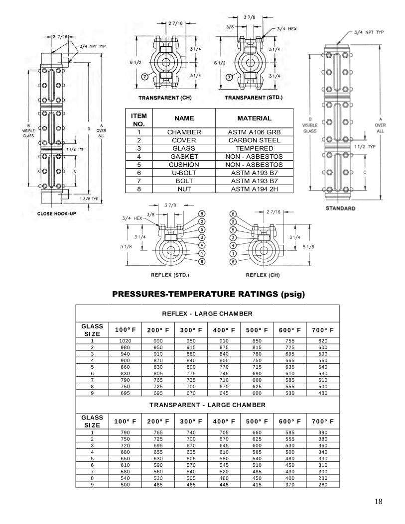
GLASSSIZE 100º F 200º F 300º F 400º F 500º F 600º F 700º F
1 1020 990 950 910 850 755 6202 980 950 915 875 815 725 6003 940 910 880 840 780 695 5904 900 870 840 805 750 665 5605 860 830 800 770 715 635 5406 830 805 775 745 690 610 5307 790 765 735 710 660 585 5108 750 725 700 670 625 555 5009 695 695 670 645 600 530 480
GLASSSIZE 100º F 200º F 300º F 400º F 500º F 600º F 700º F
1 790 765 740 705 660 585 3902 750 725 700 670 625 555 3803 720 695 670 645 600 530 3604 680 655 635 610 565 500 3405 650 630 605 580 540 480 3306 610 590 570 545 510 450 3107 580 560 540 520 485 430 3008 540 520 505 480 450 400 2809 500 485 465 445 415 370 260
REFLEX - LARGE CHAMBER
TRANSPARENT - LARGE CHAMBER
PRESSURES-TEMPERATURE RATINGS (psig)
ITEM NO.
NAME MATERIAL
1 CHAMBER ASTM A106 GRB2 COVER CARBON STEEL3 GLASS TEMPERED4 GASKET NON - ASBESTOS5 CUSHION NON - ASBESTOS6 U-BOLT ASTM A193 B77 BOLT ASTM A193 B78 NUT ASTM A194 2H
18

SPECIALTY GAGES: Heated/Cooled Externally Example: 71 TL-HC (No. 7 glass, 1-section,
Transparent, Low Pressure, Externally Heated/Cooled Gage)
Also available in close hook-up (CH) and internally heated/cooled type.
Glass-Trac Externally Heated/Cooled Gages may be either low Pressure or Mid Pressure or Mid Pressure, Reflex or Transparent and have ½” or ¾” NPT Connections. Pressure-temperature ratings and sizes remain the same as standard flat gages. On externally heated/cooled gages a metal tube is employed to transmit heating or cooling fluid. The tubing starts from an adaptor nut on one valve, passes along a machined groove in the gage body wall and connects to the adaptor nut in the opposite valve. Fluid piped through the tubing serves as the heating or cooling media. Gage bodies (liquid chambers) are made extra long to accommodate the groove and tubing. Most common heating fluids are steam and hot water. To cool gages, methane, propane, freon and ammonia refrigerants are used. The adaptor nut on the gage valves can be fitted with either a ½” NPT Female Tank connections or a ¾” NPT Male Tank connection. Valve Types 1,2 and 4 may be used. When ordering Glass-Trac Externally Heated/ Cooled Gages, add HC to the gage size number.
19

100º F 700º F 100º F 700º F 100º F 700º F 100º F 700º F1 1 7 1/2 3 3/4 3 3/4 5 1/4 2400 1520 2000 1260 3000 1890 2500 15802 1 8 1/2 4 3/4 4 3/4 6 1/4 2325 1470 1815 1150 2910 1840 2315 14703 1 9 1/2 5 3/4 5 3/4 7 1/4 2250 1420 1630 1050 2820 1780 2130 13404 1 10 1/2 6 3/4 6 3/4 8 1/4 2175 1370 1440 900 2725 1740 1940 12305 1 11 5/8 7 7/8 7 7/8 9 3/8 2100 1320 1250 790 2630 1660 1750 11006 1 12 7/8 9 1/8 9 1/8 10 5/8 2025 1280 1065 680 2535 1600 1565 9907 1 14 10 1/4 10 1/4 11 3/4 1950 1230 875 550 2440 1540 1375 8708 1 15 5/8 11 7/8 11 7/8 13 3/8 1875 1180 690 440 2345 1480 1190 7509 1 16 3/8 12 5/8 12 5/8 14 1/8 1800 1140 500 320 2250 1420 1000 6303 2 16 3/4 13 5 3/4 14 1/2 2250 1420 1630 1050 2820 1780 2130 13404 2 18 3/4 15 6 3/4 16 1/2 2175 1370 1440 900 2725 1740 1940 12305 2 21 17 1/4 7 7/8 18 3/4 2100 1320 1250 790 2630 1660 1750 11006 2 23 1/2 19 3/4 9 1/8 21 1/4 2025 1280 1065 680 2535 1600 1565 9907 2 25 3/4 22 10 1/4 23 1/2 1950 1230 875 550 2440 1540 1375 8708 2 29 25 1/4 11 7/8 26 3/4 1875 1180 690 440 2345 1480 1190 7509 2 30 1/2 26 3/4 12 5/8 28 1/4 1800 1140 500 320 2250 1420 1000 6306 3 34 1/8 30 3/8 9 1/8 31 7/8 2025 1280 1065 680 2535 1600 1565 9907 3 37 1/2 33 3/4 10 1/4 35 1/4 1950 1230 875 550 2440 1540 1375 8708 3 42 3/8 38 5/8 11 7/8 40 1/8 1875 1180 690 440 2345 1480 1190 7509 3 44 5/8 40 7/8 12 5/8 42 3/8 1800 1140 500 320 2250 1420 1000 6307 4 49 1/4 45 1/2 10 1/4 47 1950 1230 875 550 2440 1540 1375 8708 4 55 3/4 52 11 7/8 53 1/2 1875 1180 690 440 2345 1480 1190 7509 4 58 3/4 55 12 5/8 56 1/2 1800 1140 500 320 2250 1420 1000 6307 5 61 57 1/4 10 1/4 58 3/4 1950 1230 875 550 2440 1540 1375 8708 5 69 1/8 65 3/8 11 7/8 66 7/8 1875 1180 690 440 2345 1480 1190 7509 5 72 7/8 69 1/8 12 5/8 70 5/8 1800 1140 500 320 2250 1420 1000 630
A B C D
SIZENO.
DIMENSIONS(IN INCHES)
LOW PRESSURE MID-PRESSUREREFLEX
MAX. PSIG@ TEMP.*
TRANSPARENTMAX. PSIG@ TEMP.*
REFLEXMAX. PSIG@ TEMP.*
TRANSPARENTMAX. PSIG@ TEMP.*GLASS
SIZENO.
SECT.
ITEMNO. NAME MATERIAL
1 CHAMBER CARBON STEEL2 COVER CARBON STEEL3 GLASS TEMPERED4 GASKET NON-ASBESTOS5 CUSHION NON-ASBESTOS6 U-BOLT ASTM A193 B77 BOLT ASTM A193 B78 NUT ASTM A194 2H13 TUBING COPPER14 TUBING COPPER15 FITTING STEEL
DIMENSIONS AND PRESSURE RATINGS
* Saturated steam to 350 WSP **Maximum saturated steam 600 WSP with mica shields 20
PARTS

SPECIALTY GAGE: Frost-Prevention Extensions Example: 81 RL-FP w/ 3⅝” extensions (No.8
glass, 1-section, Reflex, Low Pressure, Frost Preventive Gage with 3⅝” extensions).
Glass-Trac plastic extensions for flat gage glasses prevent frost from forming in the liquid level view slot in low temperature services. Reflex and Transparent Gages in all pressure ratings can be fitted with plastic extensions. Projecting from the view slot, the clear plastic extensions keeps the liquid level indication clearly visible. Stocked extensions are 1⅝” and 3⅝” in length. If the gage is thickly insulated, longer extensions are available. The extension is held in place by stainless steel clamps fastened to the gage cover. For extra low temperature services, Glass-Trac gages can be made of special metals. Recommended length for Frost Preventive Extensions: 1⅝” extension is standard from 80ºF ambient to 0ºF temperature. Add 1” extension length for each 100º F below 0º F. When ordering, specify length and add FP to gage size number.
21

*Saturated steam to 300 WSP **Maximum saturated steam 600 WSP with mica shields
100º F 700º F 100º F 700º F 100º F 700º F 100º F 700º F1 1 5 1/4 3 3/4 3 3/4 2400 1520 2000 1260 3000 1890 2500 15802 1 6 1/4 4 3/4 4 3/4 2325 1470 1815 1150 2910 1840 2315 14703 1 7 1/4 5 3/4 5 3/4 2250 1420 1630 1050 2820 1780 2130 13404 1 8 1/4 6 3/4 6 3/4 2175 1370 1440 900 2725 1740 1940 12305 1 9 3/8 7 7/8 7 7/8 2100 1320 1250 790 2630 1660 1750 11006 1 10 5/8 9 1/8 9 1/8 2025 1280 1065 680 2535 1600 1565 9907 1 11 3/4 10 1/4 10 1/4 1950 1230 875 550 2440 1540 1375 8708 1 13 3/8 11 7/8 11 7/8 1875 1180 690 440 2345 1480 1190 7509 1 14 1/8 12 5/8 12 5/8 1800 1140 500 320 2250 1420 1000 6303 2 14 1/2 13 5 3/4 2250 1420 1630 1050 2820 1780 2130 13404 2 16 1/2 15 6 3/4 2175 1370 1440 900 2725 1740 1940 12305 2 18 3/4 17 1/4 7 7/8 2100 1320 1250 790 2630 1660 1750 11006 2 21 1/4 19 3/4 9 1/8 2025 1280 1065 680 2535 1600 1565 9907 2 23 1/2 22 10 1/4 1950 1230 875 550 2440 1540 1375 8708 2 26 3/4 25 1/4 11 7/8 1875 1180 690 440 2345 1480 1190 7509 2 28 1/4 26 3/4 12 5/8 1800 1140 500 320 2250 1420 1000 6306 3 31 7/8 30 3/8 9 1/8 2025 1280 1065 680 2535 1600 1565 9907 3 35 1/4 33 3/4 10 1/4 1950 1230 875 550 2440 1540 1375 8708 3 40 1/8 38 5/8 11 7/8 1875 1180 690 440 2345 1480 1190 7509 3 42 3/8 40 7/8 12 5/8 1800 1140 500 320 2250 1420 1000 6307 4 47 45 1/2 10 1/4 1950 1230 875 550 2440 1540 1375 8708 4 53 1/2 52 11 7/8 1875 1180 690 440 2345 1480 1190 7509 4 56 1/2 55 12 5/8 1800 1140 500 320 2250 1420 1000 6307 5 58 3/4 57 1/4 10 1/4 1950 1230 875 550 2440 1540 1375 8708 5 66 7/8 65 3/8 11 7/8 1875 1180 690 440 2345 1480 1190 7509 5 70 5/8 69 1/8 12 5/8 1800 1140 500 320 2250 1420 1000 630
LOW PRESSURE MID-PRESSUREREFLEX
MAX. PSIG@ TEMP.*
TRANSPARENTMAX. PSIG@ TEMP.*
REFLEXMAX. PSIG@ TEMP.*
TRANSPARENTMAX. PSIG@ TEMP.*A B C
SIZENO.
DIMENSIONS(IN INCHES)
GLASSSIZE
NO.SECT.
ITEMNO. NAME MATERIAL
1 CHAMBER CARBON STEEL2 COVER CARBON STEEL3 GLASS TEMPERED4 GASKET NON-ASBESTOS5 CUSHION NON-ASBESTOS6 U-BOLT ASTM A193 B77 BOLT ASTM A193 B78 NUT ASTM A192 2H9 EXTENSION PLASTIC10 CLIP 303 SS11 SCREW 303 SS
DIMENSIONS AND PRESSURE RATINGS
PARTS
22

GAGE ACCESSORY: Illuminators (Explosion-Proof)
The Quest-Tec Solutions See-Level™ LED Illuminator for hazardous locations utilizes the latest technology to provide brilliant green back lighting to any process gage. Innovative circuitry allows for the use of an individual light source every ½” along the length of any gage. With a life span of over 100,000 hours each, light source is likely to never need replacing. Even in the event of an individual lamp failure, the design provides lighting overlap ensuring that the fluid level is always illuminated. All of this is accomplished with a meager 5 watts of power usage. Through the use of new attachment techniques, the See-Level™ Illuminator readily mounts to any brand of existing or new process gages in a matter of minutes without the loosening of any cover bolting. Mounting requires no special tools or modifications to the existing structure. Set it up, attach the power and go! It’s that easy. The modular design allows for a single illuminator to be manufactured to your specific visible length eliminating the labor involved in mounting and wiring multiple illuminators.
23

LIQUID LEVEL GAGE VOLUMES
NOTE: For multiple section level gages, add “C” volume for each additional section. “C” is volume between gage sections.
GLASSSIZENO.
A
1 4 1/2"2 5 1/2"3 6 1/2"4 7 1/2"5 8 5/8"6 9 7/8"7 11"8 12 5/8"9 13 3/8"
ITEMNO.
PART MATERIAL
8 STEM NUT CARBON STEEL9 NAME PLATE 304 SS22 LEVER DUCTILE IRON23 BOLT CARBON STEEL24 NUT CARBON STEEL
CU. IN. CU. CM CU. IN. CU. CM. CU. IN. CU. CM CU. IN. CU. CM.
1 3 3/4 2.07 34 3.17 52 15.49 254 15.92 2612 4 3/4 2.61 43 3.99 65 19.16 314 19.70 3233 5 3/4 3.21 53 4.82 79 22.82 374 23.48 3854 6 3/4 3.68 60 5.63 92 26.49 434 27.26 4475 7 7/8 4.28 70 6.55 107 30.61 501 31.51 5166 9 1/8 4.94 81 7.58 124 35.19 577 36.24 5947 10 1/4 5.55 91 8.50 139 39.31 644 40.49 6648 11 7/8 6.42 105 9.83 161 45.26 742 46.64 7649 12 5/8 6.82 112 10.45 171 48.01 787 49.47 811
STANDARD GAGE VOLUMES(APPROXIMATE)
LARGE CHAMBER GAGE VOLUMES(APPROXIMATE)
GLASSSIZENO.
VISIBLELENGTH(INCHES)
REFLEX TRANSPARENT TRANSPARENTREFLEX
B C D
1 5/16" 11/16" 11/16"
Glass-Trac standard gage glass is made of borosilicate glass. For higher temperature service or requirements, aluminosilicate glass can be supplied. Mica shields are available for use with Transparent Gages in steam boiler service enabling glass to be used in higher pressures. They are placed between gasket and glass. KEL-F® shields are available for use with Transparent Gages in corrosive service. NOTE: For cyclic temperature applications, or to aid in torque retention, spring washers are available upon request.
QUICK-OPENING LEVERS Glass-Trac Gage Valves are available with a coarse thread stem design and levers for fast, remote operation by chain. Only ¼ turn of the lever opens or closes the valves, which may be mounted in hard-to-reach areas. A ¼” hole is drilled in the end of each lever for connecting the chain.
A B C
+0 +1/32" +0-1/32" -0 1/32"
TOLERANCE FOR DIMENSIONS ABOVE
24
DIMENSIONAL DATA Flat Gage Glasses
PARTS

GAGE CONNECTIONS All Glass-Trac gage valves, types 1 thru 7, can be fitted with any gage connection shown here.
PARTS
*O-Ring of Teflon® or Viton® on request. **3/4” NPT female spherical connections are not available. Note: Valve shown is for bottom left hand (or top right hand) location. Opposite hand is reversed. Valve are furnished in pairs of one bottom left hand and one top left hand.
STANDARD 316 SS WETTED PARTSMATERIAL MATERIAL
1 BODY FORGED STEEL 316 SS2 UNION NUT CARBON STEEL CARBON STEEL25 MALE CONNECTOR - 1/2" CARBON STEEL 316 SS26 MALE SPHERICAL CONN. - 3/4" CARBON STEEL 316 SS26 MALE SPHERICAL CONN. - 1/2" CARBON STEEL 316 SS27 SPHERICAL NUT CARBON STEEL CARBON STEEL28 MALE "O" RING CONN. - 1/2" CARBON STEEL 316 SS*29 "O" RING BUNA-N BUNA-NN31 FEMALE UNION - 3/4" ALLOY STEEL -34 MALE "O" RING CONN. - 3/4" CARBON STEEL 316 SS47 ANSI RF SLIP-ON FLG'D ASSY. CARBON STEEL 316 SS
**65 FEMALE SPER. CONN. - 1/2" CARBON STEEL 316 SS
ITEMNO.
NAME
25
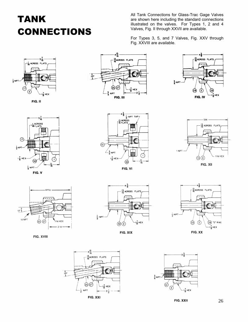
TANK CONNECTIONS
All Tank Connections for Glass-Trac Gage Valves are shown here including the standard connections illustrated on the valves. For Types 1, 2 and 4 Valves, Fig. II through XXVII are available. For Types 3, 5, and 7 Valves, Fig. XXV through Fig. XXVIII are available.
26

PARTS
TANK CONNECTIONS (CONTINUED)
* Has floating tailpiece for ± 1/8” maximum misalignment on the overall center-to-center. **O-Ring of Teflon® or Viton® on request. ***3/4” NPT female connection is not available. Note: Valve is for bottom left hand (or top right hand) location. Opposite hand is reversed. Valves are furnished in pairs of one bottom left hand and one top left hand. Viton® is a registered trademark of DuPont.
STANDARD 316 SS WETTED PARTSMATERIAL MATERIAL
1 BODY FORGED STEEL 316 SS1 BODY - 1/2" NPT SHANK FORGED STEEL 316 SS1 BODY - 3/4" NPT SHANK FORGED STEEL 316 SS1 BODY - 1" NPT SHANK FORGED STEEL 316 SS1 BODY - RF FLG'D SHANK FORGED STEEL 316 SS2 UNION NUT CARBON STEEL CARBON STEEL
*13 MALE CONNECTOR CARBON STEEL 316 SS17 FEMALE CONNECTOR - 1/2" CARBON STEEL 316 SS26 MALE SPHERICAL CONN. CARBON STEEL 316 SS27 SPHERICAL NUT CARBON STEEL CARBON STEEL
*28 MALE "O" RING CONN. - 3/4" CARBON STEEL 316 SS**29 "O" RING BUNA-N BUNA-N30 HEATED/COOLED NUT CARBON STEEL CARBON STEEL31 FEMALE CONNECTION - 3/4" ALLOY STEEL -
*32 MALE CONNECTOR - 1/2" CARBON STEEL 316 SS*33 MALE "O" RING CONN. - 1/2" CARBON STEEL 316 SS47 ANSI RF SLIP-ONFLG'D ASSY. CARBON STEEL 316 SS
***65 FEMALE SPHER. CONN. - 1/2" CARBON STEEL 316 SS
ITEMNO
NAME
27

GLASSNO.
NO.SECT.
** 1/2"-NPT
FEMALESCREWED
CAT. 1S, 2S. 4S
** 1/2"-NPT
FEMALESCREWED
CAT. 1U, 2U. 4U
1/2"-NPTMALE
UNIONFIG. VIII
1/2"-NPTMALE
SPHERICALFIG. XIV
**3/4"-NPTFEMALE
SCREWEDCAT. 1S, 2S,
4S
3/4"-NPTFEMALE
SCREWEDCAT. 1U, 2U,
4U
3/4"-NPTMALE
UNIONFIG. XI
3/4"-NPTMALE
SPHERICALFIG. X
1 1 5 1/4 3 3/4 3 3/4 8 1/2 11 11 5/8 12 3/4 8 3/4 11 5/8 11 1/2 12 5/82 1 6 1/4 4 3/4 4 3/4 9 1/2 12 12 5/8 13 3/4 9 3/4 12 5/8 12 1/2 13 5/83 1 7 1/4 5 3/4 5 3/4 10 1/2 13 13 5/8 14 3/4 10 3/4 13 5/8 13 1/2 14 5/84 1 8 1/4 6 3/4 6 3/4 11 1/2 14 14 5/8 15 3/4 11 3/4 14 5/8 14 1/2 15 5/85 1 9 3/8 7 7/8 7 7/8 12 5/8 15 1/8 15 3/4 16 7/8 12 7/8 15 3/4 15 5/8 16 3/46 1 10 5/8 9 1/8 9 1/8 13 7/8 16 3/8 17 18 1/8 14 1/8 17 16 7/8 187 1 11 3/4 10 1/4 10 1/4 15 17 1/2 18 1/8 19 1/4 15 1/4 18 1/8 18 19 1/88 1 13 3/8 11 7/8 11 7/8 16 5/8 19 1/8 19 3/4 20 7/8 16 7/8 19 3/4 19 5/8 20 3/49 1 14 1/8 12 5/8 12 5/8 17 3/8 19 7/8 20 1/2 21 5/8 17 5/8 20 1/2 20 3/8 21 1/23 2 14 1/2 13 5 3/4 17 3/4 20 1/4 20 7/8 22 18 20 7/8 20 3/4 21 7/84 2 16 1/2 15 6 3/4 19 3/4 22 1/4 22 7/8 24 20 22 7/8 22 3/4 23 7/85 2 18 3/4 17 1/4 7 7/8 22 24 1/2 25 1/8 26 1/4 22 1/4 25 1/8 25 26 1/86 2 21 1/4 19 3/4 9 1/8 24 1/2 27 27 5/8 28 3/4 24 3/4 27 5/8 27 1/2 28 5/87 2 23 1/2 22 10 1/4 26 3/4 29 1/4 29 7/8 31 27 29 7/8 29 3/4 30 7/88 2 26 3/4 25 1/4 11 7/8 30 32 1/2 33 1/8 34 1/4 30 1/4 33 1/8 33 34 1/89 2 28 1/4 26 3/4 12 5/8 31 1/2 34 34 5/8 35 3/4 31 3/4 34 5/8 34 1/2 35 5/86 3 31 7/8 30 3/8 9 1/8 35 1/8 37 5/8 38 1/4 39 3/8 35 5/8 38 1/4 38 1/8 39 1/47 3 35 1/4 33 3/4 10 1/4 38 1/2 41 41 5/8 42 3/4 38 3/4 41 5/8 41 1/2 42 5/88 3 40 1/8 38 5/8 11 7/8 43 3/8 45 7/8 46 1/2 47 5/8 43 5/8 46 1/2 46 3/8 47 1/29 3 42 3/8 40 7/8 12 5/8 45 5/8 48 1/8 48 3/4 49 7/8 45 7/8 48 3/4 48 5/8 49 3/47 4 47 45 1/2 10 1/4 50 1/4 52 3/4 53 3/8 54 1/2 50 1/2 53 5/8 53 1/4 54 3/88 4 53 1/2 52 11 7/8 56 3/4 59 1/4 59 7/8 61 57 59 7/8 59 3/4 60 7/89 4 56 1/2 55 12 5/8 59 3/4 62 1/4 62 7/8 64 60 62 7/8 62 3/4 63 7/87 5 58 3/4 57 1/4 10 1/4 62 64 1/2 65 1/8 66 1/4 62 1/4 65 1/8 65 66 1/88 5 66 7/8 65 3/8 11 7/8 70 1/8 12 5/8 73 1/4 74 3/8 70 3/8 73 1/4 73 1/8 74 1/49 5 70 5/8 69 1/8 12 5/8 73 7/8 76 3/8 77 78 1/8 74 1/8 77 76 7/8 788 6 80 1/4 78 3/4 11 7/8 83 1/2 86 86 5/8 87 3/4 83 3/4 86 5/8 86 1/2 87 5/89 6 84 3/4 83 1/4 12 5/8 88 90 1/2 91 1/8 92 1/4 88 1/4 91 1/8 91 92 1/88 7 93 5/8 92 1/8 11 7/8 96 7/8 99 3/8 100 101 1/8 97 1/8 100 99 7/8 1019 7 98 7/8 97 3/8 12 5/8 102 1/8 104 5/8 105 1/4 106 3/8 102 3/8 105 1/4 105 1/8 106 1/48 8 107 105 1/2 11 7/8 110 1/4 112 3/4 113 3/8 114 1/2 110 1/2 113 3/8 113 1/4 114 3/89 8 113 111 1/2 12 5/8 116 1/4 118 3/4 119 3/8 120 1/2 116 1/2 119 3/8 119 1/4 120 3/88 9 120 3/8 118 7/8 11 7/8 123 5/8 126 1/8 126 3/4 127 7/8 123 7/8 126 3/4 126 5/8 127 3/49 9 127 1/8 125 5/8 12 5/8 130 3/8 132 7/8 133 1/2 134 5/8 130 5/8 133 1/2 133 3/8 134 1/2
D*MINIMUM VALVE CENTER-TO-CENTER
WITH GAGE CONNECTIONFOR GAGES
TAPPED 1/2" NPTFOR GAGES
TAPPED 3/4" NPT
SIZE NO.
AGAGE
OVERALL
BVISIBLEGLASS
CVISIBLEGLASS
INSTALLATION: STANDARD GAGES
*Dimensions in column “D” apply to low-pressure (series “L”), mid-pressure (series “M”), ½” NPT high-pressure (series “H”), frost-free (all series), and internally heated/cooled reflex and transparent level gages tapped ½” NPT or ¾” NPT. For installation dimensions on other level gages see footnote. **These dimensions use close pipe nipples. For short ½” nipple add ¾”; for short ¾” nipple add 11/4”. Note: Use the following constants for other level gages.
1. Low pressure (series “L”) large chamber, add 1” to above “A” and “D” dimensions. 2. Low-pressure (series “L”), mid-pressure (series “M”) externally heated/cooled, add 2¼” to above “D” dimensions. 3. For valve Types 3, 5, or 7, add ⅞” to Column “D” to obtain minimum centers. 4. For High Pressure (series “H”) with ¾” NPT, add 1½” to dimensions “A” and”D”. 5. For a ½” NPT Female Spherical Gage connection (Figure XXIX), add 1⅞”.
NOTE: A, B, C, D Dimensions are in inches
28

er: Questtec Solutions is a young company with
the liquid level gage and valve product lines
measurement companies, Daniel Measurement and Control, directed this product development and engineering.
September 27, 2001, the Daniel liquid level gage and valve product lines were purchased by Questtec Solutions at Questtec have
Questtec relocated
erings such as Magnetic Level gages, High Pressure Steam gages and Electronic Boiler trim.
When choosing your liquid level measurement solution provider, why not choose
Questtec to be best suited to assist you solve your liquid level measurement challenges.
QUESTTEC SOLUTIONS
LIQUID LEVEL GAUGES & VALVES
QUEST-TEC SOLUTIONS | PAGE 2
88
88
SIZE NO. MINIMUM CENTER-TO-CENTER TANK CONNECTIONS
OFFSET VALVE HANDLES OFFSET VALVE HANDLES
11
21
31
41
51
61
71
81
91
32
42
52
62
72
82
92
63
73
83
93
74
84
94
75
85
95
86
96
87
97
88
98
89
99
INSTALLATION: CLOSE HOOK-UP GAGES(GAGE CONNECTIONS)
STRAIGHT-THRU VALVE
CLOSE HOOK-UP WITH HANDLE INSIDE
CLOSE HOOK-UP WITH HANDLE OUTSIDE
QUESTTEC SOLUTIONS
LIQUID LEVEL GAUGES & VALVES
QTS_LiquidLevelGagesValves_20170627.indd Spread 2 of 2 - Pages(2, 3) 6/27/17 10:24 AM

mechanical stress or accident rather than
be considered. Four basic precautions when
1. Proper glass selection
2. Correct installation.
3. Periodic inspection and cleaning.
4. Replacement as necessary.
Proper glass selection involves size, pressure
should be crystal clear and without blemish;
results in breakage, a multiple-section gage with shorter glasses should be considered.
Installation involves proper seating on gaskets and cushions; glass-to-metal contact should not occur; do not install any glass with scratches or chipped
edges; do not tighten gage bolts when gage is in use; use torque instructions provided with gage;
vessel center-to-centers are correct and vertical.
extremely important, so that no unusual stress is introduced into the glass.
scratches, chipped edges on glass; inspect glass
and cushions should be automatically replaced to reduce risk; make sure gage or tubular valves
en than similar glasses used in low temperature services.
CAUTION
GLASS-TRAC GAGE ASSEMBLY(Nummbers Indiccate Proper BBolt Torquuing Sequeence.)
GUAGE SERIES TORQUE (TIGHTEN IN 4 – 5 FT-LB. STEPS)
.bL-.tF 02rebmahC egraL erusserP woL
.bL-.tF 23erusserP-diM
.bL-.tF 04erusserP-hgiH
13960 S. Wayside, Houston, Texas 77048Toll Free: 866.240.9906 | Tel: 281.240.0440 | Fax: [email protected]
WWW.QTSLEVEL.COM000-00 06/17
ASME Sec. VIII Div I BPVC ASME “S” & “R”
Stamp holder
ISO 9001: 2008
Registered
CNC Precision
components
LIQUID LEVEL GAGES & VALVES
QTS_LiquidLevelGagesValves_20170627.indd Spread 1 of 2 - Pages(4, 1) 6/27/17 10:24 AM


