Page 1
Glenair Environmental and HermeticMIL-DTL-38999 Type Bulkhead Feed-Thrus
SECTION E TABLE OF CONTENTS
GLENAIR MIL-DTL-38999 TYPE BULKHEAD FEED-THRUS:
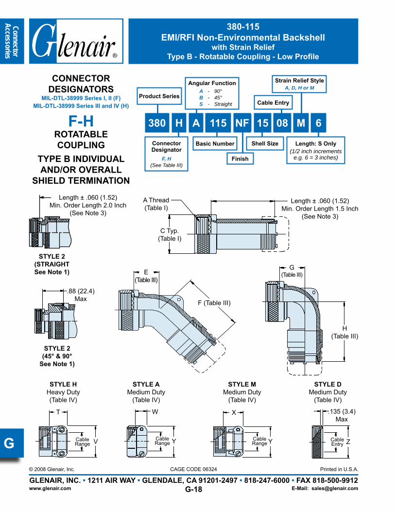
MIL-DTL-38999 Type Bulkhead Feed-Thru Product Features......................................................E-1
231-103-H7 Series I Type Jam Nut Mount Hermetic Bulkhead Feed-Thru..................................E-2
231-104-00 Series I Type Wall Mount Environmental Bulkhead Feed-Thru.................................E-3
231-104-07 Series I Type Jam Nut Mount Environmental Bulkhead Feed-Thru.....................E-4
231-104-09 Series I Type Jam Nut Mount Env. Plug/Receptacle Bulkhead Feed-Thru.................E-5
947-101 Series I Type Flange Mount Pressure Vessel Penetrator.................................................E-6
232-103-H7 Series II Type Jam Nut Mount Hermetic Bulkhead Feed-Thru.................................E-7
232-104-00 Series II Type Wall Mount Environmental Bulkhead Feed-Thru............................E-8
233-103-H7 Series III Type Jam Nut Mount Hermetic Bulkhead Feed-Thru..............................E-10
233-104-00 Series III Type Wall Mount Environmental Bulkhead Feed-Thru..........................E-11
233-104-07 Series III Type Jam Nut Mount Environmental Bulkhead Feed-Thru...................E-12
233-103-H9 Series III Type Jam Nut Mount Hermetic Plug/Receptacle Bulkhead Feed-Thru.........E-13
947-112 Series III Type Jam Nut Mount Pressure Vessel Penetrator.........................................E-14
Page 2
Bul
khea
dFe
ed-T
hrus
GLENAIR, INC. • 1211 AIR WAY • GLENDALE, CA 91201-2497 • 818-247-6000 • FAX 818-500-9912Printed in U.S.A.
www.glenair.com
CAGE CODE 06324© 2008 Glenair, Inc.
E-Mail: [email protected]
E
Glenair Hermetic and EnvironmentalMIL-DTL-38999 Type
Bulkhead Feed-Thrus
Product ApplicationsBulkhead feed-thrus eliminate the need
to permanently fix cable harnesses to panels–affording increased system flexibility, superior mechanical integrity, and greater serviceability. Glenair hermetic and environmental bulkhead feed-thru connectors are available in MIL-DTL-38999 Series I, II and III configurations. Hermetic Versions are ideally suited for high-pressure/low-leakage applications in air, sea and space environments, meeting a leak rate of 1 X 10⁻⁷ cm3 per second. Environmental versions offer IP67 level sealing.
The Widest Range of MIL-DTL-38999 Type Bulkhead Feed-Thru Connectors Available In The Industry.
ErrataCatalog contents—including part numbers,
materials and dimensions—are accurate to the best of our ability when we go to print. Even so, customers are advised to consult the factory for the latest specifications, particularly to confirm critical dimensions such as connector lengths, threads, and so on. When errors or mistakes are brought to our attention, corrected content is posted immediately to our website: www.glenair.com.
TABLE I: MATERIALSShell, Barrel, and Coupling Nut (Environmental) Aluminum alloy 6061 per ASTM-B211
Shell, Barrel Coupling and Jam Nut (Hermetic) Stainless steel per AMS-QQ-S-763
Shell, Barrel, Coupling Nut and Jam Nut (Hermetic) Carbon Steel per ASTM-B545 or ASTM-B339
Grommet, Peripheral Seal and Interfacial Seal Blended elastomer, 30% silicone per ZZ-R-765, 70% fluorosilicone per MIL-R-25988
Hermetic Insert Vitreous glass
Feed-Thru Contacts (Environmental) Copper Alloy / Gold Plate
Feed-Thru (Hermetic) Nickel-iron alloy per ASTM F30 (Alloy 52),50 microinches gold plated per ASTM B488 Type 3 Code C Class 1,27 over nickel plate per QQ-N-290 Class 2, 50-100 microinches
Adhesives Silicone and epoxy
TABLE II: POPULAR FINISHESPlating Code Material Finish Specification
M Aluminum Electroless Nickel AMS-C-26074
NF Aluminum Cadmium Plate Olive Drab over Electroless Nickel AMS-QQ-P-416, over AMS-C-26074 (1000 Hour Salt Spray)
NC Aluminum Zinc-Cobalt ASTMB840
ZN Aluminum Olive Drab Zinc-Nickel Zinc alloy per ASTM B841-91, Class 1 Type E Grade 3 over Electroless nickel per ASTM B733-90 SC2, Type 1 Class 5
MT Aluminum Ni-PTFE 1,000 Hour GreyTM (Nickel Fluorocarbon Polymer) MIL-DTL-38999L (500 Hour Salt Spray)
AL Aluminum Pure Electrodeposited Aluminum MIL-DTL-83488 (1000 Hour Salt Spray)Z1 Stainless Steel Passivate AMS-QQ-P-35FT Carbon Steel Fused Tin Plate ASTM-B545 or ASTM-B339ZL Stainless Steel Electrodeposited Nickel SAE-AMS-QQ-N-290, Class 2
Page 3
Bulkhead
Feed-Thrus
GLENAIR, INC. • 1211 AIR WAY • GLENDALE, CA 91201-2497 • 818-247-6000 • FAX 818-500-9912Printed in U.S.A.
www.glenair.com
CAGE CODE 06324© 2008 Glenair, Inc.
E-Mail: [email protected]
E
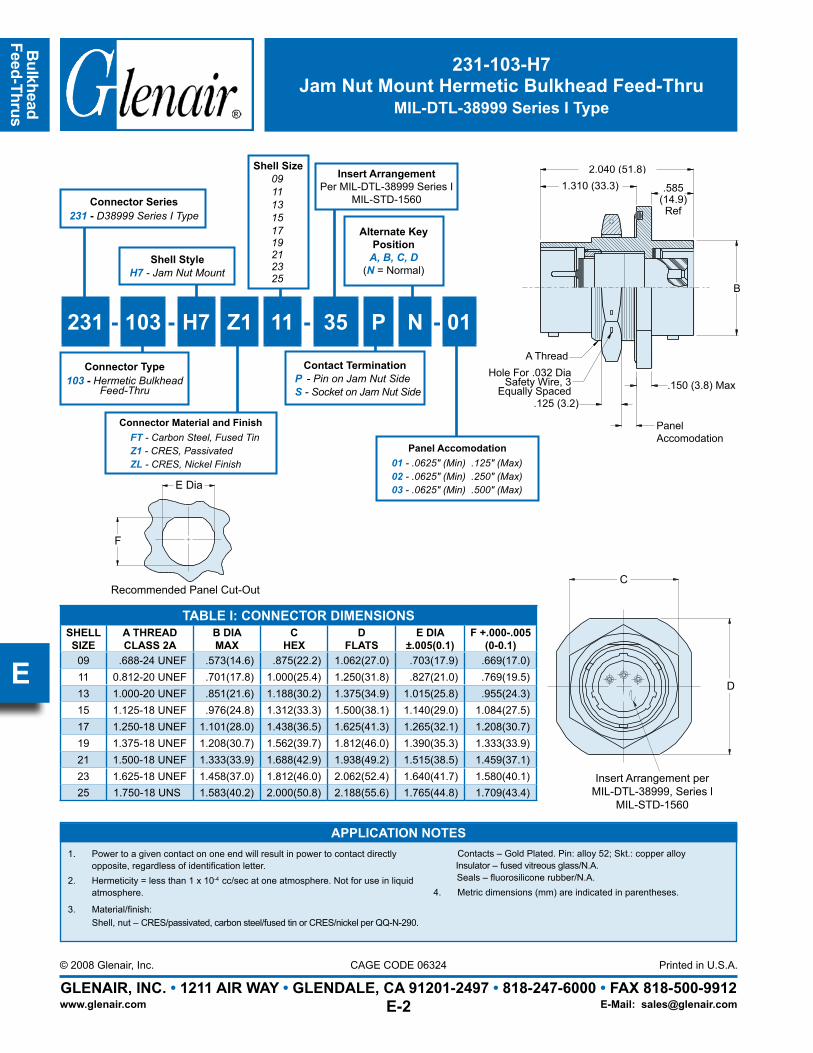
231-103-H7Jam Nut Mount Hermetic Bulkhead Feed-Thru
MIL-DTL-38999 Series I Type
TABLE I: CONNECTOR DIMENSIONSSHELLSIZE
A THREADCLASS 2A
B DIAMAX
CHEX
DFLATS
E DIA±.005(0.1)
F +.000-.005(0-0.1)
09 .688-24 UNEF .573(14.6) .875(22.2) 1.062(27.0) .703(17.9) .669(17.0)11 0.812-20 UNEF .701(17.8) 1.000(25.4) 1.250(31.8) .827(21.0) .769(19.5)13 1.000-20 UNEF .851(21.6) 1.188(30.2) 1.375(34.9) 1.015(25.8) .955(24.3)15 1.125-18 UNEF .976(24.8) 1.312(33.3) 1.500(38.1) 1.140(29.0) 1.084(27.5)17 1.250-18 UNEF 1.101(28.0) 1.438(36.5) 1.625(41.3) 1.265(32.1) 1.208(30.7)19 1.375-18 UNEF 1.208(30.7) 1.562(39.7) 1.812(46.0) 1.390(35.3) 1.333(33.9)21 1.500-18 UNEF 1.333(33.9) 1.688(42.9) 1.938(49.2) 1.515(38.5) 1.459(37.1)23 1.625-18 UNEF 1.458(37.0) 1.812(46.0) 2.062(52.4) 1.640(41.7) 1.580(40.1)25 1.750-18 UNS 1.583(40.2) 2.000(50.8) 2.188(55.6) 1.765(44.8) 1.709(43.4)
Insert Arrangement perMIL-DTL-38999, Series l
MIL-STD-1560
C
D
2.040 (51.8)1.310 (33.3) .585
(14.9)Ref
.150 (3.8) Max
Panel Accomodation
.125 (3.2)
Hole For .032 Dia Safety Wire, 3
Equally Spaced
A Thread
B
E Dia
Recommended Panel Cut-Out
F
Insert ArrangementPer MIL-DTL-38999 Series I
MIL-STD-1560Connector Series231 - D38999 Series I Type
Alternate Key Position
A, B, C, D(N = Normal)
Contact TerminationP - Pin on Jam Nut SideS - Socket on Jam Nut Side
Shell Size091113151719212325
231 - 103 - H7 Z1 11 - 35 P N - 01
Shell StyleH7 - Jam Nut Mount
Connector Material and FinishFT - Carbon Steel, Fused TinZ1 - CRES, PassivatedZL - CRES, Nickel Finish
Connector Type103 - Hermetic Bulkhead
Feed-Thru
Panel Accomodation01 - .0625″ (Min) .125″ (Max)02 - .0625″ (Min) .250″ (Max)03 - .0625″ (Min) .500″ (Max)
APPLICATION NOTESPower to a given contact on one end will result in power to contact directly 1. opposite, regardless of identification letter.Hermeticity = less than 1 x 10². -4 cc/sec at one atmosphere. Not for use in liquid atmosphere.
Material/finish: 3. Shell, nut – CRES/passivated, carbon steel/fused tin or CRES/nickel per QQ-N-290.
Contacts – Gold Plated. Pin: alloy 52; Skt.: copper alloy Insulator – fused vitreous glass/N.A. Seals – fluorosilicone rubber/N.A.
Metric dimensions (mm) are indicated in parentheses.4.
Page 4
Bul
khea
dFe
ed-T
hrus
GLENAIR, INC. • 1211 AIR WAY • GLENDALE, CA 91201-2497 • 818-247-6000 • FAX 818-500-9912Printed in U.S.A.
www.glenair.com
CAGE CODE 06324© 2008 Glenair, Inc.
E-Mail: [email protected]
E
231-104-00Wall Mount Environmental Bulkhead Feed-Thru
MIL-DTL-38999 Series I Type
TABLE I: CONNECTOR DIMENSIONSSHELLSIZE
AMAX
BSQ
CSQ
DDIA
E±.005(0.1)
09 .573(14.6) .719(18.3) .938(23.8) .125(3.2) .703(17.9)
11 .701(17.8) .812(20.6) 1.031(26.2) .125(3.2) .827(21.0)
13 .851(21.6) .906(23.0) 1.125(28.8) .125(3.2) 1.015(25.8)
15 .976(24.8) .969(24.6) 1.219(31.0) .125(3.2) 1.140(29.0)
17 1.101(28.0) 1.062(27.0) 1.312(33.3) .125(3.2) 1.265(32.1)
19 1.208(30.7) 1.156(29.4) 1.438(36.5) .125(3.2) 1.390(35.3)
21 1.333(33.9) 1.250(31.8) 1.562(39.7) .125(3.2) 1.515(38.5)
23 1.458(37.0) 1.375(34.9) 1.688(42.9) .156(4.0) 1.640(41.7)
25 1.583(40.2) 1.500(38.1) 1.812(46.0) .156(4.0) 1.765(44.8)
.150 Max
A TYP
Flange SideRef
1.56 Max
.84 Ref
B Typ
C
D DIATYP
Insert Arrangement perMIL-DTL-38999, Series lMIL-STD-1560
APPLICATION NOTESMaterial/finish: 1. Shells and nuts – Al alloy, 6061-T6, QQ-A-225/8, see Table I (D5) Contacts – Leaded nickel copper/gold plate MIL-G-45204, Type II, Class I Bayonet pins – AISI 300 series stainless steel/passivate, QQ-P-35 Hoods – AISI 305 series stainless steel/passivate, QQ-P-35 Inserts – Epiall 1908 Seals – Silicone per ZZ-R-765Metric Dimensions (mm) are indicated in parentheses.2.
E DIA
Recommended Panel Cutout
B Ref
Connector Series231 - D38999 Series I Type
Contact TerminationP - Pin on Flange SideS - Socket on Flange Side
Shell Size091113151719212325
231 - 104 - 00 M 11 - 35 P N - 01
Connector Type104 - Env. Bulkhead Feed-Thru
Connector Material and FinishM - Aluminum / Electroless NickelNC - Aluminum / Zinc-CobaltNF - Cad / O.D. Over Electroless Nickel (1000hr Salt Spray)ZN - Aluminum Zinc-Nickel Olive DrabMT - Aluminum / Ni-PTFE 1000 Hour GreyTM
AL - Aluminum / Pure Electrodeposited Aluminum
Alternate Key Position
A, B, C, D(N = Normal)
Shell Style00 - Wall Mount
Panel Accom.
Panel Accomodation01 - .0625″ (Min) .125″ (Max)02 - .0625″ (Min) .250″ (Max)03 - .0625″ (Min) .500″ (Max)
Insert ArrangementPer MIL-DTL-38999 Series I
MIL-STD-1560
Page 5
Bulkhead
Feed-Thrus
GLENAIR, INC. • 1211 AIR WAY • GLENDALE, CA 91201-2497 • 818-247-6000 • FAX 818-500-9912Printed in U.S.A.
www.glenair.com
CAGE CODE 06324© 2010 Glenair, Inc.
E-Mail: [email protected]
F EDia
F
Recommended Panel Cut-Out
D
C
Insert arrangement, perMIL-C-38999, Series l
MIL-STD-1560
2.540 Max
1.810 Max .585Ref
B
A ThreadHole for .032 Dia
Safety Wire, 3 Equally Spaced
.125
.150 Max
PanelAccomodation
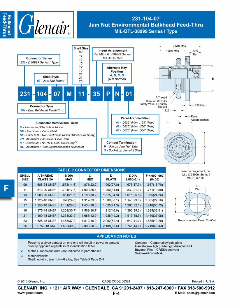
231-104-07Jam Nut Environmental Bulkhead Feed-Thru
MIL-DTL-38999 Series I Type
TABLE I: CONNECTOR DIMENSIONSSHELLSIZE
A THREADCLASS 2A
B DIAMAX
CHEX
DFLATS
E DIA±.005(0.1)
F +.000-.002(0-.06)
09 .688-24 UNEF .573(14.6) .875(22.2) 1.062(27.0) .678(17.7) .657(16.70)
11 .813-20 UNEF .701(17.8) 1.000(25.4) 1.250(31.8) .830(21.1) .771(19.59)
13 1.000-20 UNEF .851(21.6) 1.188(30.2) 1.375(34.9) 1.015(25.8) .955(24.26)
15 1.125-18 UNEF .976(24.8) 1.312(33.3) 1.500(38.1) 1.140(29.0) 1.085(27.56)
17 1.250-18 UNEF 1.101(28.0) 1.438(36.5) 1.625(41.3) 1.265(32.1) 1.210(30.73)
19 1.375-18 UNEF 1.208(30.7) 1.562(39.7) 1.812(46.0) 1.390(35.3) 1.335(33.91)
21 1.500-18 UNEF 1.333(33.9) 1.688(42.9) 1.938(49.2) 1.515(38.5) 1.460(37.08)
23 1.625-18 UNEF 1.458(37.0) 1.812(46.0) 2.062(52.4) 1.640(41.7) 1.585(40.26)25 1.750-18 UNS 1.583(40.2) 2.000(50.8) 2.188(55.6) 1.765(44.8) 1.710(43.43)
APPLICATION NOTES1. Power to a given contact on one end will result in power to contact
directly opposite regardless of identification letter2. Metric Dimensions (mm) are indicated in parentheses3. Material/finish:
Shell, lockring, jam nut—Al alloy, See Table II Page D-5
Contacts—Copper alloy/gold plate Insulators—High grade rigid dielectric/N.A. Bayonet Pins—CRES/passivate Seals—silicone/N.A.
Connector Series231 - D38999 Series I Type
Contact TerminationP - Pin on Jam Nut SideS - Socket on Jam Nut Side
Shell Size091113151719212325
231 - 104 - 07 M 11 - 35 P N - 01
Connector Type104 - Env. Bulkhead Feed-Thru
Alternate Key Position
A, B, C, D(N = Normal)
Shell Style07 - Jam Nut Mount
Panel Accomodation01 - .0625″ (Min) .125″ (Max)02 - .0625″ (Min) .250″ (Max)03 - .0625″ (Min) .500″ (Max)
Connector Material and FinishM - Aluminum / Electroless NickelNC - Aluminum / Zinc-CobaltNF - Cad / O.D. Over Electroless Nickel (1000hr Salt Spray)ZN - Aluminum Zinc-Nickel Olive DrabMT - Aluminum / Ni-PTFE 1000 Hour GreyTM
AL - Aluminum / Pure Electrodeposited Aluminum
Insert ArrangementPer MIL-DTL-38999 Series I
MIL-STD-1560
Page 6
Bul
khea
dFe
ed-T
hrus
GLENAIR, INC. • 1211 AIR WAY • GLENDALE, CA 91201-2497 • 818-247-6000 • FAX 818-500-9912Printed in U.S.A.
www.glenair.com
CAGE CODE 06324© 2008 Glenair, Inc.
E-Mail: [email protected]
E
231-104-09Jam Nut Mount Environmental
Plug/Receptacle Bulkhead Feed-Thrufor MIL-DTL-38999 Series I Type
TABLE I: CONNECTOR DIMENSIONS
SHELLSIZE
A THREADCLASS 2A
B DIAMAX
CMAX
DHEX
EFLATS
F DIA±.005(0.1)
G+.000-.005
(0-0.1)09 .688-24 UNEF .573(14.6) .900(22.9) .875(22.2) 1.062(27.0) .703(17.9) .699(17.8)11 0.813-20 UNEF .701(17.8) 1.030(26.2) 1.000(25.4) 1.250(31.8) .827(21.0) .769(19.5)13 1.000-20 UNEF .851(21.6) 1.205(30.6) 1.188(30.2) 1.375(34.9) 1.015(25.8) .955(24.3)15 1.125-18 UNEF .976(24.8) 1.325(33.7) 1.312(33.3) 1.500(38.1) 1.140(29.0) 1.084(27.5)17 1.250-18 UNEF 1.101(28.0) 1.450(36.8) 1.438(36.5) 1.625(41.3) 1.265(32.1) 1.208(30.7)19 1.375-18 UNEF 1.208(30.7) 1.565(39.8) 1.562(39.7) 1.812(46.0) 1.390(35.3) 1.333(33.9)21 1.500-18 UNEF 1.333(33.9) 1.690(42.9) 1.688(42.9) 1.938(49.2) 1.515(38.5) 1.459(37.1)23 1.625-18 UNEF 1.458(37.0) 1.795(45.6) 1.812(46.0) 2.062(52.4) 1.640(41.7) 1.580(40.1)25 1.750-18 UNS 1.583(40.2) 1.920(48.8) 2.000(50.8) 2.188(55.6) 1.765(44.8) 1.709(43.4)
APPLICATION NOTESMaterial/finish: 1. Shell assembly, coupling nut, jam nut, lock ring—Aluminum Alloy, See Table II Contacts—Copper alloy/gold plate Bayonet pins, wave washer—CRES/passivate
O-Ring, interfacial and peripheral seals—silicone/N.A. Insulators—High grade rigid dielectric/N/A. Ground Ring—Beryllium copper/gold plateMetric Dimensions (mm) are indicated in parentheses.2.
Shell Size091113151719212325
Contact TerminationP - Pin on Plug SideS - Socket on Plug Side
Connector Series231 - D38999 Series I Type
231 - 104 - 09 M 11 - 35 P N - 01
Connector Type104 - Env. Bulkhead
Feed-Thru
Shell Style09 - Jam Nut Mount Plug/Receptacle Gender Changer
Panel Accomodation01 - .0625″ (Min) .125″ (Max)02 - .0625″ (Min) .250″ (Max)03 - .0625″ (Min) .500″ (Max)
Alternate Key Position
A, B, C, D(N = Normal)
PanelAccomodation
Connector Material and FinishM - Aluminum / Electroless NickelNC - Aluminum / Zinc-CobaltNF - Cad / O.D. Over Electroless Nickel (1000hr Salt Spray)ZN - Aluminum Zinc-Nickel Olive DrabMT - Aluminum / Ni-PTFE 1000 Hour GreyTM
AL - Aluminum / Pure Electrodeposited Aluminum
Insert Arrangement perMIL-DTL-38999, Series lMIL-STD-1560
Insert ArrangementPer MIL-DTL-38999 Series I
MIL-STD-1560
Page 7
Bulkhead
Feed-Thrus
GLENAIR, INC. • 1211 AIR WAY • GLENDALE, CA 91201-2497 • 818-247-6000 • FAX 818-500-9912Printed in U.S.A.
www.glenair.com
CAGE CODE 06324© 2008 Glenair, Inc.
E-Mail: [email protected]
E
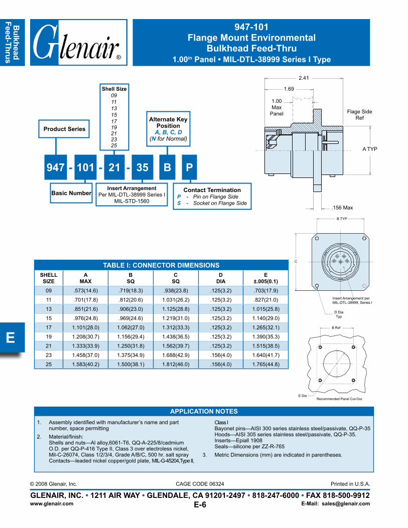
947-101Flange Mount Environmental
Bulkhead Feed-Thru1.00in Panel • MIL-DTL-38999 Series I Type
TABLE I: CONNECTOR DIMENSIONSSHELLSIZE
AMAX
BSQ
CSQ
DDIA
E±.005(0.1)
09 .573(14.6) .719(18.3) .938(23.8) .125(3.2) .703(17.9)
11 .701(17.8) .812(20.6) 1.031(26.2) .125(3.2) .827(21.0)
13 .851(21.6) .906(23.0) 1.125(28.8) .125(3.2) 1.015(25.8)
15 .976(24.8) .969(24.6) 1.219(31.0) .125(3.2) 1.140(29.0)
17 1.101(28.0) 1.062(27.0) 1.312(33.3) .125(3.2) 1.265(32.1)
19 1.208(30.7) 1.156(29.4) 1.438(36.5) .125(3.2) 1.390(35.3)
21 1.333(33.9) 1.250(31.8) 1.562(39.7) .125(3.2) 1.515(38.5)
23 1.458(37.0) 1.375(34.9) 1.688(42.9) .156(4.0) 1.640(41.7)
25 1.583(40.2) 1.500(38.1) 1.812(46.0) .156(4.0) 1.765(44.8)
A TYP
.156 Max
2.41
1.69
1.00Max
Panel Flage SideRef
C
D DiaTyp
Insert Arrangement perMIL-DTL-38999, Series l
B TYP
APPLICATION NOTESAssembly identified with manufacturer’s name and part 1. number, space permittingMaterial/finish: 2. Shells and nuts—Al alloy,6061-T6, QQ-A-225/8/cadmium O.D. per QQ-P-416 Type II, Class 3 over electroless nickel, Mil-C-26074, Class 1/2/3/4, Grade A/B/C, 500 hr. salt spray Contacts—leaded nickel copper/gold plate, MIL-G-45204,Type II,
Class I Bayonet pins—AISI 300 series stainless steel/passivate, QQ-P-35 Hoods—AISI 305 series stainless steel/passivate, QQ-P-35. Inserts—Epiall 1908 Seals—silicone per ZZ-R-765Metric Dimensions (mm) are indicated in parentheses.3.
B Ref
Recommended Panel Cut-OutE Dia
Product Series
Basic Number
Alternate Key Position
A, B, C, D(N for Normal)
947 - 101 - 21 - 35 B P
Contact TerminationP - Pin on Flange SideS - Socket on Flange Side
Shell Size091113151719212325
Insert ArrangementPer MIL-DTL-38999 Series I
MIL-STD-1560
Page 8
Bul
khea
dFe
ed-T
hrus
GLENAIR, INC. • 1211 AIR WAY • GLENDALE, CA 91201-2497 • 818-247-6000 • FAX 818-500-9912Printed in U.S.A.
www.glenair.com
CAGE CODE 06324© 2008 Glenair, Inc.
E-Mail: [email protected]
E
232-103-H7Jam Nut Mount Hermetic Bulkhead Feed-Thru
MIL-DTL-38999 Series II Type
TABLE I: CONNECTOR DIMENSIONSSHELLSIZE
A THREADCLASS 2A
B DIAMAX
CHEX
DFLATS
E DIA±.005(0.1)
F +.000-.005(0-0.1)
08 .875-20 UNEF .474(12.0) 1.062(27.0) 1.250(31.8) .885(22.5) .830(21.1)
10 1.000-20 UNEF .591(15.0) 1.188(30.2) 1.375(34.9) 1.010(25.7) .955(24.3)
12 1.125-18 UNEF .751(19.1) 1.312(33.3) 1.500(38.1) 1.135(28.8) 1.085(27.6)
14 1.250-18 UNEF .876(22.3) 1.438(36.5) 1.625(41.3) 1.260(32.0) 1.210(30.7)
16 1.375-18 UNEF 1.001(25.4) 1.562(39.7) 1.781(45.2) 1.385(35.2) 1.335(33.9)
18 1.500-18 UNEF 1.126(28.6) 1.688(42.9) 1.890(48.0) 1.510(38.4) 1.460(37.1)
20 1.625-18 UNEF 1.251(31.8) 1.812(46.0) 2.016(51.2) 1.635(41.5) 1.585(40.3)
22 1.750-18 UNS 1.376(35.0) 2.000(50.8) 2.140(54.4) 1.760(44.7) 1.710(43.4)
24 1.875-16 UN 1.501(38.1) 2.125(54.0) 2.265(57.5) 1.885(47.9) 1.835(46.6)
1.69 Max
.915 REF
B TYP
.150 Max
.125
Hole for .032 DIA Safety Wire, 3 Equally Spaced
A Thread
D
C
Recommended Panel Cut-Out
E Dia
F
Connector Series232 - D38999 Series II Type
Contact TerminationP - Pin on Jam Nut SideS - Socket on Jam Nut Side
Shell Size081012141618202224
232 - 103 - H7 Z1 10 - 35 P N - 01
Shell StyleH7 - Jam Nut Mount
Connector Material and FinishFT - Carbon Steel, Fused TinZ1 - CRES, PassivatedZL - CRES, Nickel Finish
Connector Type103 - Hermetic Bulkhead
Feed-Thru
Alternate Key Position
A, B, C, D(N = Normal)
Panel Accomodation01 - .0625″ (Min) .125″ (Max)02 - .0625″ (Min) .250″ (Max)03 - .0625″ (Min) .500″ (Max)
Panel Accom.
APPLICATION NOTESPower to a given contact on one end will result in power to contact directly 1. opposite, regardless of identification letter.Hermeticity = less than 1 x 10². -4 cc/sec at one atmosphere. Not for use in liquid atmosphere.
Material/finish: 3. Shell, nut – CRES/passivated, carbon steel/fused tin or CRES/nickel per QQ-N-290.
Contacts – Gold Plated. Pin: alloy 52; Skt.: copper alloy Insulator – fused vitreous glass/N.A. Seals – fluorosilicone rubber/N.A.
Metric dimensions (mm) are indicated in parentheses.4.
Insert Arrangement perMIL-DTL-38999, Series IlMIL-STD-1560
Insert ArrangementPer MIL-DTL-38999 Series II
MIL-STD-1560
Page 9
Bulkhead
Feed-Thrus
GLENAIR, INC. • 1211 AIR WAY • GLENDALE, CA 91201-2497 • 818-247-6000 • FAX 818-500-9912Printed in U.S.A.
www.glenair.com
CAGE CODE 06324© 2008 Glenair, Inc.
E-Mail: [email protected]
E
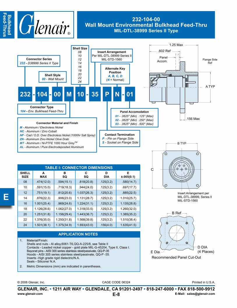
232-104-00Wall Mount Environmental Bulkhead Feed-Thru
MIL-DTL-38999 Series II Type
TABLE I: CONNECTOR DIMENSIONSSHELLSIZE
AMAX
BSQ
CSQ
DDIA
E±.005(0.1)
08 .474(12.0) .594(15.1) .818(20.8) .125(3.2) .580(14.7)
10 .591(15.0) .719(18.3) .944(24.0) .125(3.2) .697(17.7)
12 .751(19.1) .812(20.6) 1.037(26.3) .125(3.2) .885(22.5)
14 .876(22.3) .906(23.0) 1.131(28.7) .125(3.2) 1.010(25.7)
16 1.001(25.4) .969(24.6) 1.224(31.1) .125(3.2) 1.135(28.8)
18 1.126(28.6) 1.062(27.0) 1.318(33.5) .125(3.2) 1.260(32.0)
20 1.251(31.8) 1.156(29.4) 1.443(36.7) .125(3.2) 1.385(35.2)
22 1.376(35.0) 1.250(31.8) 1.568(39.8) .125(3.2) 1.510(38.4)
24 1.501(38.1) 1.375(34.9) 1.693(43.0) .156(4.0) 1.635(41.5)
A TYP
.156 Max
1.25 Max
.602 Ref
APPLICATION NOTESMaterial/Finish: 1. Shells and nuts – Al alloy,6061-T6,QQ-A-225/8, see Table II Contacts – Leaded nickel copper - gold plate MIL-G-45204, Type II, Class I. Bayonet pins – AISI 300 series stainless steel/passivate, QQ-P-35 Hoods – AISI 305 series stainless steel/passivate, QQ-P -35. Inserts –High grade rigid dielectric/N.A. Seals – Silicone/ N.A.Metric Dimensions (mm) are indicated in parentheses.2.
Insert Arrangement perMIL-DTL-38999, Series lIMIL-STD-1560
B TYP
C
Recommended Panel Cut-OutE Dia
D DIA(4 Places)
B Ref
Connector Series232 - D38999 Series II Type
Contact TerminationP - Pin on Flange SideS - Socket on Flange Side
Shell Size081012141618202224
232 - 104 - 00 M 10 - 35 P N - 01
Shell Style00 - Wall Mount
Connector Type104 - Env. Bulkhead Feed-Thru
Alternate Key Position
A, B, C, D(N = Normal)
Panel Accomodation01 - .0625″ (Min) .125″ (Max)02 - .0625″ (Min) .250″ (Max)03 - .0625″ (Min) .500″ (Max)
PanelAccom. Flange Side
Ref
Connector Material and FinishM - Aluminum / Electroless NickelNC - Aluminum / Zinc-CobaltNF - Cad / O.D. Over Electroless Nickel (1000hr Salt Spray)ZN - Aluminum Zinc-Nickel Olive DrabMT - Aluminum / Ni-PTFE 1000 Hour GreyTM
AL - Aluminum / Pure Electrodeposited Aluminum
Insert ArrangementPer MIL-DTL-38999 Series II
MIL-STD-1560
Page 10
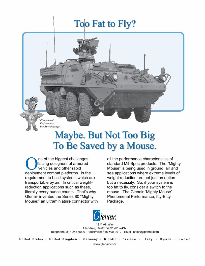
Maybe. But Not Too Big To Be Saved by a Mouse.
One of the biggest challenges facing designers of armored vehicles and other rapid
deployment combat platforms is the requirement to build systems which are transportable by air. In critical weight-reduction applications such as these, literally every ounce counts. That’s why Glenair invented the Series 80 “Mighty Mouse;” an ultraminiature connector with
all the performance characteristics of standard Mil-Spec products. The “Mighty Mouse” is being used in ground, air and sea applications where extreme levels of weight reduction are not just an option but a necessity. So, if your system is too fat to fly, consider a switch to the mouse. The Glenair “Mighty Mouse”: Phenomenal Performance, Itty-Bitty Package.
1211 Air WayGlendale, California 91201-2497
Telephone: 818-247-6000 · Facsimilie: 818-500-9912 · EMail: [email protected]
U n i t e d S t a t e s • U n i t e d K i n g d o m • G e r m a n y • N i o r d i c • F r a n c e • I t a l y • S p a i n • J a p a n
www.glenair.com
Too Fat to Fly?
“Phenomenal Performance; Itty-Bitty Package”
Page 11
Bulkhead
Feed-Thrus
GLENAIR, INC. • 1211 AIR WAY • GLENDALE, CA 91201-2497 • 818-247-6000 • FAX 818-500-9912Printed in U.S.A.
www.glenair.com
CAGE CODE 06324© 2010 Glenair, Inc.
E-Mail: [email protected]
F
233-103-H7Jam Nut Mount Hermetic Bulkhead Feed-Thru
MIL-DTL-38999 Series III Type
Insert Arrangement per MIL-DTL-38999 Series III MIL-STD-1560
B
C
D Dia
Recommended Panel Cut-Out
E
.23Max
2.03 Max
1.34Max
A Thread
F Thread
Connector Series233 - D38999 Series III Type
Contact TerminationP - Pin on Jam Nut SideS - Socket on Jam Nut Side
Shell Size091113151719212325
233 - 103 - H7 Z1 11 - 35 P N - 01
Shell StyleH7 - Jam Nut Mount
Connector Material and FinishZ1 - CRES, PassivatedZL - CRES, Nickel Finish
Connector Type103 - Hermetic Bulkhead
Feed-Thru
Alternate Key Position
A, B, C, D, E(N = Normal)
Panel Accomodation01 - .0625″ (Min) .125″ (Max)02 - .0625″ (Min) .250″ (Max)03 - .0625″ (Min) .500″ (Max)
PanelAccom.
APPLICATION NOTES1. Power to a given contact on one end will result in power to contact directly
opposite, regardless of identification letter.2. Hermeticity = less than 1 x 10⁻⁷ cc/sec at one atmosphere. Not for use in liquid
atmosphere.
3. Material/finish: Shell, nut – CRES/passivated, carbon steel/fused tin or CRES/nickel per QQ-N-290.
Contacts – Gold Plated. Pin: alloy 52; Skt.: copper alloy Insulator – fused vitreous glass/N.A. Seals – fluorosilicone rubber/N.A.4. Metric dimensions (mm) are indicated in parentheses.
Insert ArrangementPer MIL-DTL-38999 Series III
MIL-STD-1560
TABLE I: CONNECTOR DIMENSIONSSHELLSIZE
A THREAD0.1 P-0.3L-TS-2
BDIA C D
DIAE
DIMF THREAD
METRIC
09 .6250 1.189 (30.20) 1.063 (27.00) .703/.693 (17.9/17.6) .657/.655 (16.7/16.6) M17 x 1.0-6g
11 .7500 1.375 (34.93) 1.252 (31.80) .835/.825 (21.2/21.0) .771/.769 (19.6/19.5) M20 x 1.0-6g13 .8750 1.500 (38.10) 1.374 (34.90) 1.020/1.010 (25.9/25.7) .955/.953 (24.3/24.2) M25 x 1.0-6g15 1.0000 1.626 (41.30) 1.500 (38.10) 1.145/1.135 (29.1/28.8) 1.085/1.083 (27.6/27.5) M28 x 1.0-6g17 1.1875 1.752 (44.50) 1.626 (41.30) 1.270/1.260 (32.3/32.0) 1.210/1.208 (30.7/30.7) M32 x 1.0-6g19 1.2500 1.937 (49.20) 1.811 (46.00) 1.395/1.385 (35.4/35.2) 1.335/1.333 (33.9/33.9) M35 x 1.0-6g21 1.3750 2.063 (52.40) 1.937 (49.20) 1.520/1.510 (38.6/38.4) 1.460/1.458 (35.7/37.0) M38 x 1.0-6g23 1.5000 2.189 (55.60) 2.063 (52.40) 1.645/1.635 (41.8/41.5) 1.585/1.583 (40.3/40.2) M41 x 1.0-6g25 1.6250 2.311 (58.70) 2.189 (55.60) 1.769/1.759 (44.9/44.7) 1.710/1.708 (43.4/43.4) M44 x 1.0-6g
Page 12
Bul
khea
dFe
ed-T
hrus
GLENAIR, INC. • 1211 AIR WAY • GLENDALE, CA 91201-2497 • 818-247-6000 • FAX 818-500-9912Printed in U.S.A.
www.glenair.com
CAGE CODE 06324© 2010 Glenair, Inc.
E-Mail: [email protected]
F
233-104-00Wall Mount Environmental Bulkhead Feed-Thru
MIL-DTL-38999 Series III Type
APPLICATION NOTES1.
Shell, lock ring—Al alloy, see Table II Contacts—Copper alloy/gold plate Insulators—High grade rigid dielectric/N.A. Seals—Silicone/N.A.
2. For symetrical layouts only. Power to a given contact on one end will result in power to contact directly opposite,
letter.3. Metric Dimensions
(mm) are indicated in parentheses
TABLE I: CONNECTOR DIMENSIONSSHELLSIZE
A THREAD0.1 P-0.3L-2A
B DIA.± 0.010 (0.3) C DIM. D DIM.
09 .625 .128 (3.3) .719 (18.3) .938 (23.8)11 .750 .128 (3.3) .812 (20.6) 1.031 (26.2)13 .875 .128 (3.3) .906 (23.0) 1.125 (28.6)15 1.000 .128 (3.3) .969 (24.6) 1.219 (31.0)17 1.188 .128 (3.3) 1.062 (27.0) 1.312 (33.3)19 1.250 .128 (3.3) 1.156 (29.4) 1.438 (36.5)21 1.375 .128 (3.3) 1.250 (31.8) 1.562 (39.7)23 1.500 .156 (4.0) 1.375 (34.9) 1.688 (42.9)25 1.625 .156 (4.0) 1.500 (38.1) 1.812 (46.0)
C S Q
I NS E RT A RRANGE ME NTSS E E MI L - C- 38999 F OR
S QD
A THRE AD
. 75 RE F
. 62
1. 53 MAX
4 PL ACE SB DI A
. 125 MAX PANEL ACCOMMODATI ON( THI S S I DE ONL Y)
. 520 MAX. F UL L Y MATE D I NDI CATOR RE D BAND 2 PL ACE S
E Max D Sq.
.62
A Thread
.75 Ref
.510 MaxFully Mated Indicator Red Band2 Places
B Diameter4 Places
C Sq.
Flange Mount
Panel Accomodation
Flange SideRef
Insert Arrangement per MIL-DTL-38999 Series III MIL-STD-1560
Connector Series233 - D38999 Series III Type
Contact TerminationP - Pin on Panel SideS - Socket on Panel Side
Shell Size091113151719212325
233 - 104 - 00 M 11 - 35 P N - 01
Shell Style00 - Wall Mount
Connector Type104 - Env. Bulkhead Feed-Thru
Alternate Key Position
A, B, C, D, E(N = Normal)
Connector Material and FinishM - Aluminum / Electroless NickelNC - Aluminum / Zinc-CobaltNF - Cad / O.D. Over Electroless Nickel (1000hr Salt Spray)ZN - Aluminum Zinc-Nickel Olive DrabMT - Aluminum / Ni-PTFE 1000 Hour GreyTM
AL - Aluminum / Pure Electrodeposited Aluminum
Insert ArrangementPer MIL-DTL-38999 Series III
MIL-STD-1560
PanelSideRef
Panel Accomodation E Max01 - .0625″ (Min) .125″ (Max) 1.53”02 - .0625″ (Min) .250″ (Max) 1.66”03 - .0625″ (Min) .500″ (Max) 1.91”
Page 13
Bulkhead
Feed-Thrus
GLENAIR, INC. • 1211 AIR WAY • GLENDALE, CA 91201-2497 • 818-247-6000 • FAX 818-500-9912Printed in U.S.A.
www.glenair.com
CAGE CODE 06324© 2010 Glenair, Inc.
E-Mail: [email protected]
F
APPLICATION NOTES1. Assembly identified with Glenair name, part number and date code,
space permitting.2. For pin/pin and socket/socket, symetrical layouts only. Consult factory
for available insert arrangements3. Power to a given contact on one end will result in power to contact
directly opposite regardless of identification letter
4. Material/finish: Shell, lockring, jam nut—Al alloy, see Table II Contacts—Copper alloy/gold plate Insulators—High grade rigid dielectric/N.A. Bayonet Pins—CRES/passivate Seals—Silicone/N.A.
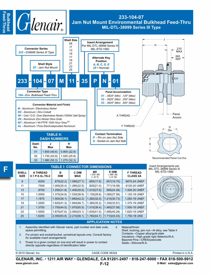
233-104-07Jam Nut Mount Environmental Bulkhead Feed-Thru
MIL-DTL-38999 Series III Type
Connector Series233 - D38999 Series III Type
Contact TerminationP - Pin on Jam Nut SideS - Socket on Jam Nut Side
Shell Size091113151719212325
233 - 104 - 07 M 11 - 35 P N - 01
Shell Style07 - Jam Nut Mount
Connector Type104 - Env. Bulkhead Feed-Thru
Alternate Key Position
A, B, C, D, E(N = Normal)
Panel Accomodation01 - .0625″ (Min) .125″ (Max)02 - .0625″ (Min) .250″ (Max)03 - .0625″ (Min) .500″ (Max)Connector Material and Finish
M - Aluminum / Electroless NickelNC - Aluminum / Zinc-CobaltNF - Cad / O.D. Over Electroless Nickel (1000hr Salt Spray)ZN - Aluminum Zinc-Nickel Olive DrabMT - Aluminum / Ni-PTFE 1000 Hour GreyTM
AL - Aluminum / Pure Electrodeposited Aluminum
947-114
RECOMMENDED PANEL CUT-OUT
D DIA
E
BULKHEAD FEEDTHRU JAM NUT,FOR MIL-C-38999, SERIES III
CONNECTOR, RECEPTACLE,
B
C
SEE MIL-C-38999 FORINSERT ARRANGEMENTS
.565 REF
A THREAD
F THREAD
G MAX. PANEL
J
H.150 MAX
P = PIN ON JAM NUT SIDES = SOCKET ON JAM NUT SIDEPP = PIN TO PIN 2 3SS = SOCKET TO SOCKET 2 3
P
HOW TO ORDER:
EXAMPLE: 947 114 NF 21 35 B
PRODUCT SERIES
FINISH SYM, TABLE II
SHELL SIZE, TABLE I
INSERT ARRANGEMENT DASH NO
OMIT FOR NORMALALTERNATE POSITION, MIL-C-38999,
BASIC NO
- - 01
DASH NO, TABLE IIIPANEL THICKNESS
Insert Arrangements perMIL-DTL-38999 Series III
MIL-STD-1560
Insert ArrangementPer MIL-DTL-38999 Series III
MIL-STD-1560
TABLE II:DASH NUMBERS
DashNo.
JMax
HMax
01 1.600 (40.6) 0.900 (22.9)02 1.730 (43.9) 1.020 (25.9)03 1.980 (50.3) 1.270 (32.3)
DDia
E
Recommended Panel Cut-Out
TABLE I: CONNECTOR DIMENSIONSSHELLSIZE
A THREAD0.1 P-0.3L-TS-2
BDIM
C DIMMAX
ØD+.010/-.000(+.25/-0)
E DIM+.000/-.002(+.0/-.06)
F THREADCLASS 2A
9 .6250 .875(22.2) 1.090(27.7) .693(17.6) .657(16.70) .6875-24 UNEF11 .7500 1.000(25.4) 1.280(32.5) .825(21.0) .771(19.58) .8125-20 UNEF13 .8750 1.250(31.8) 1.400(35.6) 1.010(27.6) .995(24.26) 1.000-20 UNEF15 1.0000 1.375(34.9) 1.530(38.9) 1.135(28.8) 1.085(27.56) 1.125-18 UNEF17 1.1875 1.500(38.1) 1.660(42.2) 1.260(32.0) 1.210(30.73) 1.250-18 UNEF19 1.2500 1.625(41.3) 1.840(46.7) 1.385(35.2) 1.335(33.91) 1.375-18 UNEF21 1.3750 1.750(44.5) 1.970(50.5) 1.510(38.4) 1.460(37.08) 1.500-18 UNEF23 1.5000 1.875(47.6) 2.090(53.1) 1.635(41.5) 1.585(40.26) 1.625-18 UNEF25 1.6250 2.000(50.8) 2.210(56.1) 1.760(44.7) 1.710(43.43) 1.750-18 UNS
947-114
RECOMMENDED PANEL CUT-OUT
D DIA
E
BULKHEAD FEEDTHRU JAM NUT,FOR MIL-C-38999, SERIES III
CONNECTOR, RECEPTACLE,
B
C
SEE MIL-C-38999 FORINSERT ARRANGEMENTS
.565 REF
A THREAD
F THREAD
G MAX. PANEL
J
H.150 MAX
P = PIN ON JAM NUT SIDES = SOCKET ON JAM NUT SIDEPP = PIN TO PIN 2 3SS = SOCKET TO SOCKET 2 3
P
HOW TO ORDER:
EXAMPLE: 947 114 NF 21 35 B
PRODUCT SERIES
FINISH SYM, TABLE II
SHELL SIZE, TABLE I
INSERT ARRANGEMENT DASH NO
OMIT FOR NORMALALTERNATE POSITION, MIL-C-38999,
BASIC NO
- - 01
DASH NO, TABLE IIIPANEL THICKNESS
PanelAccom.
.210MAX
Page 14
Bul
khea
dFe
ed-T
hrus
GLENAIR, INC. • 1211 AIR WAY • GLENDALE, CA 91201-2497 • 818-247-6000 • FAX 818-500-9912Printed in U.S.A.
www.glenair.com
CAGE CODE 06324© 2010 Glenair, Inc.
E-Mail: [email protected]
F
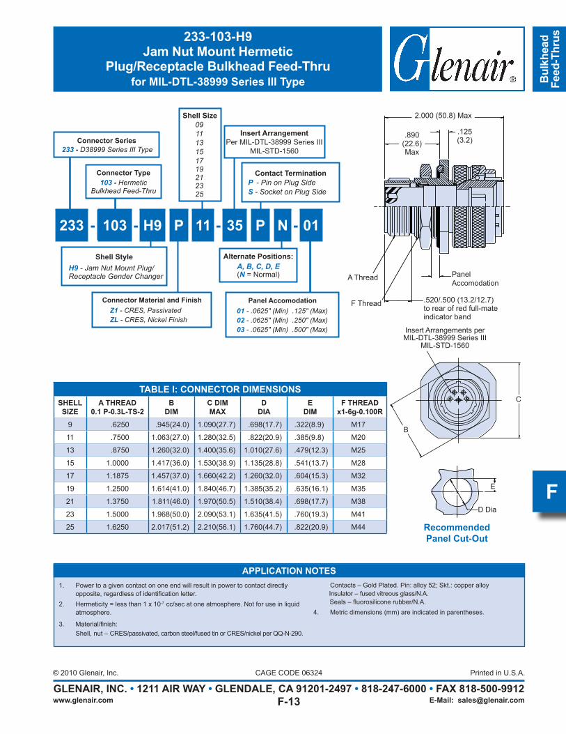
TABLE I: CONNECTOR DIMENSIONSSHELLSIZE
A THREAD0.1 P-0.3L-TS-2
BDIM
C DIMMAX
DDIA
EDIM
F THREADx1-6g-0.100R
9 .6250 .945(24.0) 1.090(27.7) .698(17.7) .322(8.9) M17
11 .7500 1.063(27.0) 1.280(32.5) .822(20.9) .385(9.8) M20
13 .8750 1.260(32.0) 1.400(35.6) 1.010(27.6) .479(12.3) M25
15 1.0000 1.417(36.0) 1.530(38.9) 1.135(28.8) .541(13.7) M28
17 1.1875 1.457(37.0) 1.660(42.2) 1.260(32.0) .604(15.3) M32
19 1.2500 1.614(41.0) 1.840(46.7) 1.385(35.2) .635(16.1) M35
21 1.3750 1.811(46.0) 1.970(50.5) 1.510(38.4) .698(17.7) M38
23 1.5000 1.968(50.0) 2.090(53.1) 1.635(41.5) .760(19.3) M41
25 1.6250 2.017(51.2) 2.210(56.1) 1.760(44.7) .822(20.9) M44
E
D Dia
RecommendedPanel Cut-Out
Insert Arrangements perMIL-DTL-38999 Series III
MIL-STD-1560
B
C
2.000 (50.8) Max
A Thread
F Thread .520/.500 (13.2/12.7)to rear of red full-mateindicator band
.890(22.6)Max
.125 (3.2)
233-103-H9Jam Nut Mount Hermetic
Plug/Receptacle Bulkhead Feed-Thrufor MIL-DTL-38999 Series III Type
Shell Size091113151719212325
Alternate Positions:A, B, C, D, E(N = Normal)
Contact TerminationP -PinonPlugSideS-SocketonPlugSide
Connector Series233 - D38999SeriesIIIType
233 - 103 - H9 P 11 - 35 P N - 01
Connector Type103 - Hermetic
BulkheadFeed-Thru
Shell StyleH9-JamNutMountPlug/ReceptacleGenderChanger
Connector Material and FinishZ1 -CRES,PassivatedZL-CRES,NickelFinish
Panel Accomodation01-.0625″(Min).125″(Max)02 -.0625″(Min).250″(Max)03-.0625″(Min).500″(Max)
Panel Accomodation
APPLICATION NOTES1. Power to a given contact on one end will result in power to contact directly
opposite, regardless of identification letter.2. Hermeticity = less than 1 x 10⁻⁷ cc/sec at one atmosphere. Not for use in liquid
atmosphere.
3. Material/finish: Shell, nut – CRES/passivated, carbon steel/fused tin or CRES/nickel per QQ-N-290.
Contacts – Gold Plated. Pin: alloy 52; Skt.: copper alloy Insulator – fused vitreous glass/N.A. Seals – fluorosilicone rubber/N.A.4. Metric dimensions (mm) are indicated in parentheses.
Insert ArrangementPer MIL-DTL-38999 Series III
MIL-STD-1560
Page 15
Bulkhead
Feed-Thrus
GLENAIR, INC. • 1211 AIR WAY • GLENDALE, CA 91201-2497 • 818-247-6000 • FAX 818-500-9912Printed in U.S.A.
www.glenair.com
CAGE CODE 06324© 2008 Glenair, Inc.
E-Mail: [email protected]
E
947-112MIL-DTL-38999 Series III Type
Jam Nut Bulkhead Feed-Thru
Product Series
Basic Number
947 - 112 M 25 - 24 B P S
FinishSee Table II
Shell SizeA - 9B - 11C - 13D - 15E - 17F - 19G - 21H - 23J - 25
Contact StyleP - Pin on Flange SideS - Socket on Flange Side
Contact StyleP - Pin on Jam Nut SideS - Socket on Jam Nut Side
Alternate Key Position
A, B, C, D,(Omit for Normal)
CONNECTOR, RECEPTACLE, BULKHEAD FEEDTHRU JAM NUT, MIL-C-38999, SERIES III (FOR 2.00 MAX PANEL)
947-112
2.00 MAX. PANEL
F THREAD
A THREAD TYP.
3.470 MAX
2.770 MAX
.125 MAX
.520 MAX FULLY MATED INDICATOR BAND - RED TYPE
C
B
SEE MIL-STD-1560 FORINSERT ARRANGEMENT
HOW TO ORDER:
EXAMPLE:
PRODUCT SERIES
BASIC NUMBER
FINISH, TABLE II
SHELL SIZE, TABLE I
INSERT ARRANGEMENT DASH NUMBERPER MIL-STD-1560
ALTERNATE POSITION, PER MIL-C-38999A, B, C, OR D OMIT FOR NORMAL
P = PIN ON JAM NUT SIDES = SOCKET ON JAM NUT SIDE
P = PIN ON FLANGE SIDES = SOCKET ON FLANGE SIDE
947 - 112 M 25 - 24 B P S
See MIL-STD-1560 forInsert Arrangement
A Thread
F Thread
Panel.520 Max Fully Mated Indicator Band - Red Type
C
B
Insert ArrangementPer MIL-DTL-38999 Series III
MIL-STD-1560
Page 16
Bul
khea
dFe
ed-T
hrus
GLENAIR, INC. • 1211 AIR WAY • GLENDALE, CA 91201-2497 • 818-247-6000 • FAX 818-500-9912Printed in U.S.A.
www.glenair.com
CAGE CODE 06324© 2008 Glenair, Inc.
E-Mail: [email protected]
E
E
ø D
RECOMMENED PANEL CUT-OUT
3. MATERIAL/FINISH: SHELL, LOCKRING, JAM NUT - AL ALLOY/TABLE II CONTACTS - COPPER ALLOY/GOLD PLATE INSULATORS - HIGH GRADE RIGID DIELECTRIC/ N.A. SEALS - FLUOROSILICONE/N.A.
2. ELECTRICAL SAFETY LIMITS MUST BE ESTABLISHED BY USER, PEAK VOLTAGE, SWITCHING SURGE, TRANSIENT, ECT.. SHOULD BE USED TO DETERMINE THE SAFETY APPLICATION.
1. ASSEMBLY IDENTIFIED WITH MANUFACTURER'S NAME AND P/N.
NOTES:
x1-6g-0.100RM17M20M25M28M32M35M38M41M441.710 (43.4)
1.585 (40.3)1.460 (37.1)1.335 (33.9)1.210 (30.7)1.085 (27.6).995 (25.3).771 (19.6).670 (17.0)
1.760 (44.7)1.635 (41.5)1.510 (38.4)1.385 (35.2)1.260 (32.0)1.135 (28.8)1.010 (27.6) .822 (20.9) .698 (17.7)
2.20 (55.9)2.08 (52.8)1.95 (49.5)1.83 (46.5)1.64 (41.7)1.52 (36.9)1.39 (35.3)1.27 (32.3)1.08 (27.4)
2.000 (50.8)1.875 (47.6)1.750 (44.5)1.625 (41.3)1.500 (38.1)1.375 (34.9)1.250 (31.8)1.000 (25.4) .875 (22.2)
1.62501.50001.37501.25001.18751.0000.8750.7500.6250
2523211917151311 9
F THREADDIME
DIAD
MAXC DIM
DIMB
0.1P-0.3L-TS-2A THREAD
SIZESHELL
TABLE I: CONNECTOR DIMENSIONS
SYM
TABLE II: MATERIALS
BJ
MN
NF
T
FINISH DESCRIPTION
CADMIUM PLATE/OLIVE DRABGOLD IRIDITE OVER CADMIUMPLATE OVER NICKELELECTROLESS NICKELCADMIUM PLATE/OLIVE DRABOVER NICKELCAD/O.D. ONER ELECTROLESSNICKEL (500 HOUR SALT SPRAY)CADMIUM PLATE/BRIGHT DIPOVER NICKEL
AND FINISH
TABLE I: CONNECTOR DIMENSIONSSHELLSIZE
A Thread0.1P-0.3L-TS-2
BDimension
CDimension Max
DDiameter
EDimension
F Threadx1-6g-0.100R
09 .6250 .875 (22.2) 1.08 (27.4) 6.98 (17.7) .670 (17.0) M17
11 .7500 1.000 (25.4) 1.27 (32.3) .822 (20.9) .771 (19.6) M20
13 .8750 1.250 (31.8) 1.39 (35.3) 1.010 (27.6) .995 (25.3) M25
15 1.0000 1.375 (34.9) 1.52 (36.9) 1.135 (28.8) 1.085 (27.6) M28
17 1.1875 1.500 (38.1) 1.64 (41.7) 1.260 (32.0) 1.210 (30.7) M32
19 1.2500 1.625 (41.3) 1.83 (46.5) 1.385 (35.2) 1.335 (33.9) M35
21 1.3750 1.750 (44.5) 1.95 (49.5) 1.510 (38.4) 1.460 (37.1) M38
23 1.5000 1.875 (47.6) 2.08 (52.8) 1.635 (41.5) 1.585 (40.3) M41
25 1.6250 2.000 (50.8) 2.20 (55.9) 1.760 (44.7) 1.710 (43.4) M44
TABLE II: MATERIALS AND FINISHSYM FINISH
B Cadmium Plate / Olive Drab
J Gold Iridite over Cadmium Plate over Nickel
M Electroless Nickel
N Cadmium Plate / Olive Drab over Nickel
NF Cadmium / Olive Drab over Electroless Nickel Nickel (500 Hour Salt Spray)
T Cadmium Plate / Bright Dip Over Nickel
APPLICATION NOTES
Assembly identified with manufacturers name and part number1. Electrical safety limits must be established by user, peak voltage, switching surge, transient, etc. should be used to determine the 2. safety applications.Material/ Finishes: 3. Shells, Jam Nut - AL Alloy Insulators- High Grade Rigid Dielectric/ N.A Seals- Fluorosilicone/ N.A.
947-112MIL-DTL-38999 Series III Type
Jam Nut Bulkhead Feed-Thru
Page 17
Glenair MIL-DTL-38999 TypeSav-Con® Connector Savers
SECTION F TABLE OF CONTENTS
GLENAIR MIL-DTL-38999 TYPE CONNECTOR SAVERS:
Glenair MIL-DTL-38999 Type Sav-Con® Connector Saver Product Features.............................F-1
Sav-Con® Connector Saver Lock Ring Selection and Use........................................................F-2
MIL-DTL-38999 Sav-Con® Material and Finish Specifications...............................................F-3
942-003 Series I Type Sav-Con® Plug/Receptacle Connector Saver.........................................F-4
GC443 Series I Type Sav-Con® Plug/Plug In-Line Connector Saver.......................................F-6
942-004 Series II Type Sav-Con® Plug/Receptacle Connector Saver.......................................F-8
942-005 Series III Type Sav-Con® Plug/Receptacle Connector Saver........................................F-10
947-221 Series III Type Sav-Con® Plug/Plug In-Line Connector Saver.....................................F-12
947-139 Series III Type Sav-Con® Pin/Pin or Socket/Socket In-Line Connector Saver............F-14
942-021 Series III Type Sav-Con® MIL-STD-1760 Connector Saver.........................................F-16
Page 18
Sav-
Con
®
Con
nect
or
Save
rs
GLENAIR, INC. • 1211 AIR WAY • GLENDALE, CA 91201-2497 • 818-247-6000 • FAX 818-500-9912Printed in U.S.A.
www.glenair.com
CAGE CODE 06324© 2008 Glenair, Inc.
E-Mail: [email protected]
F
Glenair MIL-DTL-38999 TypeSav-Con® Connector Savers
Product ApplicationsGlenair Sav-Con® Connector Savers are
designed to protect connectors that are subject to repeated mating and unmating cycles. Sav-Con® Connector Savers prevent costly repair or replacement of expensive connectors and cables while preserving the quality and integrity of connector performance. Sav-Con® Connector Savers take the abuse of repeated connection cycles instead of “black box” or other equipment connectors. Equipment connectors that are mated and unmated frequently during manufacturing, check-out phases and environmental test
The Smart Solution for Preventing Contact Damage and Extending the Service Life of Cable Assemblies
For MIL-DTL-38999 Series I, II and III Connectors
All Standard Materials and Finish Platings
Environmental and Hermetic Designs Available
Gender Changers
Optional Locking Mechanism
Keyed Polarization
Fully Repairable
design adds resistance to a circuit equal to a mated pin and socket contact, thus it has little or no effect on sensitive circuits.
When a Sav-Con® Connector Saver is installed between a receptacle and a plug, the effective additional length is less than the length of an equivalent mated plug and receptacle. When using bayonet coupled Sav-Con® Connector Savers, Glenair recommends our Lock Ring design feature in applications where large cable bundles may
induce unwanted stress to the coupling mechanism and potential unwanted contact displacement (see page E-2).
Catalog contents—including part numbers, materials and dimensions—are accurate to the best of our ability when we go to print. Even so, customers are advised to consult the factory for the latest specifications, particularly to confirm critical dimensions such as connector lengths, threads, and so on. When errors or mistakes are brought to our attention, corrected content is posted immediately to our website: www.glenair.com.
programs can be protected by Glenair Sav-Con® Connector Savers at considerable savings in time and money.
Glenair Sav-Con® Connector Savers feature one-piece, non-removable pin/socket contacts for maximum reliability and minimum effect on circuit resistance. Each Glenair Sav-Con® Connector Saver series meets the same durability requirements as the Military Specification series with which it mates. The mating portions of the pin-and-socket contacts are in strict compliance with the applicable Military Specification contacts used in each connector series. The one-piece
Page 19
Sav-Con
®
Connector Savers
GLENAIR, INC. • 1211 AIR WAY • GLENDALE, CA 91201-2497 • 818-247-6000 • FAX 818-500-9912Printed in U.S.A.
www.glenair.com
CAGE CODE 06324© 2008 Glenair, Inc.
E-Mail: [email protected]
F
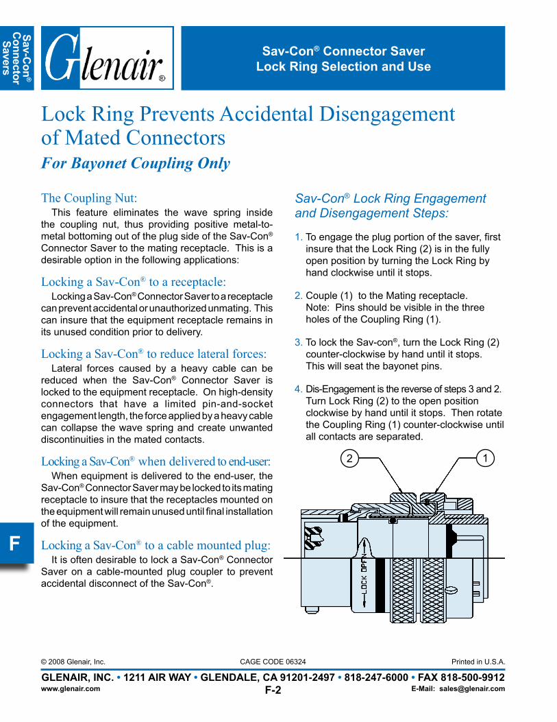
The Coupling Nut: This feature eliminates the wave spring inside
the coupling nut, thus providing positive metal-to-metal bottoming out of the plug side of the Sav-Con® Connector Saver to the mating receptacle. This is a desirable option in the following applications:
Locking a Sav-Con® to a receptacle:Locking a Sav-Con® Connector Saver to a receptacle
can prevent accidental or unauthorized unmating. This can insure that the equipment receptacle remains in its unused condition prior to delivery.
Locking a Sav-Con® to reduce lateral forces:Lateral forces caused by a heavy cable can be
reduced when the Sav-Con® Connector Saver is locked to the equipment receptacle. On high-density connectors that have a limited pin-and-socket engagement length, the force applied by a heavy cable can collapse the wave spring and create unwanted discontinuities in the mated contacts.
Locking a Sav-Con® when delivered to end-user:When equipment is delivered to the end-user, the
Sav-Con® Connector Saver may be locked to its mating receptacle to insure that the receptacles mounted on the equipment will remain unused until final installation of the equipment.
Locking a Sav-Con® to a cable mounted plug:It is often desirable to lock a Sav-Con® Connector
Saver on a cable-mounted plug coupler to prevent accidental disconnect of the Sav-Con®.
Sav-Con® Connector SaverLock Ring Selection and Use
Lock Ring Prevents Accidental Disengagement of Mated ConnectorsFor Bayonet Coupling Only
Sav-Con® Lock Ring Engagement and Disengagement Steps:
1. To engage the plug portion of the saver, firstinsure that the Lock Ring (2) is in the fully open position by turning the Lock Ring by hand clockwise until it stops.
2. Couple (1) to the Mating receptacle. Note: Pins should be visible in the three holes of the Coupling Ring (1).
3. To lock the Sav-con®, turn the Lock Ring (2)counter-clockwise by hand until it stops. This will seat the bayonet pins.
4. Dis-Engagement is the reverse of steps 3 and 2.Turn Lock Ring (2) to the open position clockwise by hand until it stops. Then rotate the Coupling Ring (1) counter-clockwise until all contacts are separated.
12
Page 20
Sav-
Con
®
Con
nect
or
Save
rs
GLENAIR, INC. • 1211 AIR WAY • GLENDALE, CA 91201-2497 • 818-247-6000 • FAX 818-500-9912Printed in U.S.A.
www.glenair.com
CAGE CODE 06324© 2008 Glenair, Inc.
E-Mail: [email protected]
F
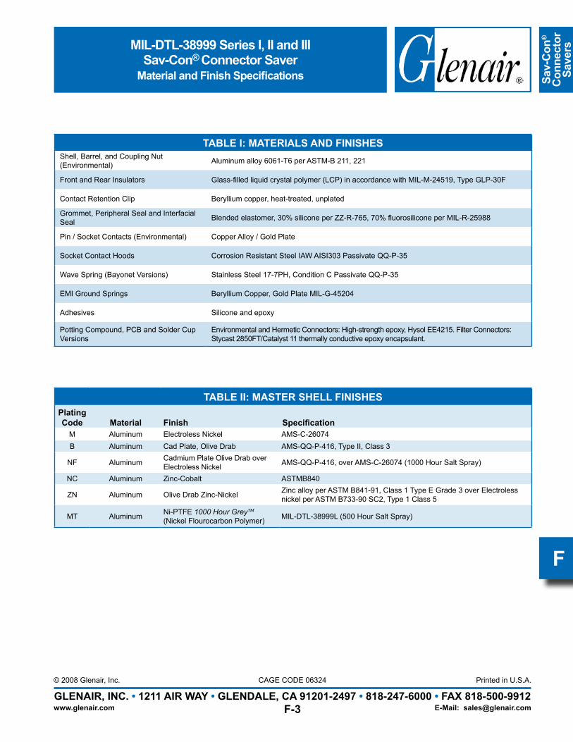
MIL-DTL-38999 Series I, II and IIISav-Con® Connector Saver
Material and Finish Specifications
TABLE I: MATERIALS AND FINISHESShell, Barrel, and Coupling Nut (Environmental) Aluminum alloy 6061-T6 per ASTM-B 211, 221
Front and Rear Insulators Glass-filled liquid crystal polymer (LCP) in accordance with MIL-M-24519, Type GLP-30F
Contact Retention Clip Beryllium copper, heat-treated, unplated
Grommet, Peripheral Seal and Interfacial Seal Blended elastomer, 30% silicone per ZZ-R-765, 70% fluorosilicone per MIL-R-25988
Pin / Socket Contacts (Environmental) Copper Alloy / Gold Plate
Socket Contact Hoods Corrosion Resistant Steel IAW AISI303 Passivate QQ-P-35
Wave Spring (Bayonet Versions) Stainless Steel 17-7PH, Condition C Passivate QQ-P-35
EMI Ground Springs Beryllium Copper, Gold Plate MIL-G-45204
Adhesives Silicone and epoxy
Potting Compound, PCB and Solder Cup Versions
Environmental and Hermetic Connectors: High-strength epoxy, Hysol EE4215. Filter Connectors: Stycast 2850FT/Catalyst 11 thermally conductive epoxy encapsulant.
TABLE II: MASTER SHELL FINISHESPlating Code Material Finish Specification
M Aluminum Electroless Nickel AMS-C-26074 B Aluminum Cad Plate, Olive Drab AMS-QQ-P-416, Type II, Class 3
NF Aluminum Cadmium Plate Olive Drab over Electroless Nickel AMS-QQ-P-416, over AMS-C-26074 (1000 Hour Salt Spray)
NC Aluminum Zinc-Cobalt ASTMB840
ZN Aluminum Olive Drab Zinc-Nickel Zinc alloy per ASTM B841-91, Class 1 Type E Grade 3 over Electroless nickel per ASTM B733-90 SC2, Type 1 Class 5
MT Aluminum Ni-PTFE 1000 Hour GreyTM (Nickel Flourocarbon Polymer) MIL-DTL-38999L (500 Hour Salt Spray)
Page 21
Sav-Con
®
Connector Savers
GLENAIR, INC. • 1211 AIR WAY • GLENDALE, CA 91201-2497 • 818-247-6000 • FAX 818-500-9912Printed in U.S.A.
www.glenair.com
CAGE CODE 06324© 2008 Glenair, Inc.
E-Mail: [email protected]
F
942-003Sav-Con® Connector Saver
Plug/Receptaclefor Use with MIL-DTL-38999 Series I
Insert ArrangementMIL-DTL-38999 Series I
MIL-STD-1560
942 L 003 M 17 - 35 P A
Alternate Positions:A, B, C, D
(N = Normal)
Product Series942 - Connector Saver
Contact GenderP - Pins on Plug Side,Sockets on Receptacle SideS - Sockets on Plug Side,Pins on Receptacle Side
Lock RingL - Lock Ring (Standard)
Finish Symbol(See Table II)
Basic PartNumber Shell Size
Lock Ring(Standard)
1.875(45.9)Max
Interfacial Seal
EMI Ground Spring(Standard)
A B
RECEPTACLEEND
PLUGEND
Page 22
Sav-
Con
®
Con
nect
or
Save
rs
GLENAIR, INC. • 1211 AIR WAY • GLENDALE, CA 91201-2497 • 818-247-6000 • FAX 818-500-9912Printed in U.S.A.
www.glenair.com
CAGE CODE 06324© 2008 Glenair, Inc.
E-Mail: [email protected]
F
942-003Sav-Con® Connector Saver
Plug/Receptaclefor Use with MIL-DTL-38999 Series I
SERIES I: ALTERNATE KEYWAY POSITIONSSHELLSIZE N° A° B° C° D°
09 95 77 -- -- 113
11 95 81 67 123 109
13 95 75 63 127 115
15 95 74 61 129 116
17 95 77 85 125 113
19 95 77 65 125 113
21 95 77 65 125 113
23 95 80 69 121 110
25 95 80 69 121 110
FACE VIEWRECEPTACLE
CD
NA
B
CL45° 27°
88°
TABLE I: CONNECTORDIMENSIONS
SHELLSIZE A Max B Diameter
Max09 .573 (14.6) .910 (23.1)
11 .701 (17.8) 1.035 (26.3)
13 .851 (21.6) 1.210 (30.7)
15 .976 (24.8) 1.330 (33.8)
17 1.101 (28.0) 1.455 (37.0)
19 1.208 (30.7) 1.570 (39.9)
21 1.333 (33.9) 1.695 (43.1)
23 1.458 (37.0) 1.800 (45.7)
25 1.583 (40.2) 1.925 (48.9)
TABLE II: SHELL FINISHESPlating Code Material Finish
M Aluminum Electroless NickelB Aluminum Cad Plate, Olive Drab
NF Aluminum Cadmium Plate Olive Drab over Electroless Nickel
NC Aluminum Zinc-Cobalt
ZN Aluminum Olive Drab Zinc-Nickel
MT Aluminum Ni-PTFE 1000 Hour GreyTM (Nickel Flourocarbon Polymer)
Page 23
Sav-Con
®
Connector Savers
GLENAIR, INC. • 1211 AIR WAY • GLENDALE, CA 91201-2497 • 818-247-6000 • FAX 818-500-9912Printed in U.S.A.
www.glenair.com
CAGE CODE 06324© 2008 Glenair, Inc.
E-Mail: [email protected]
F
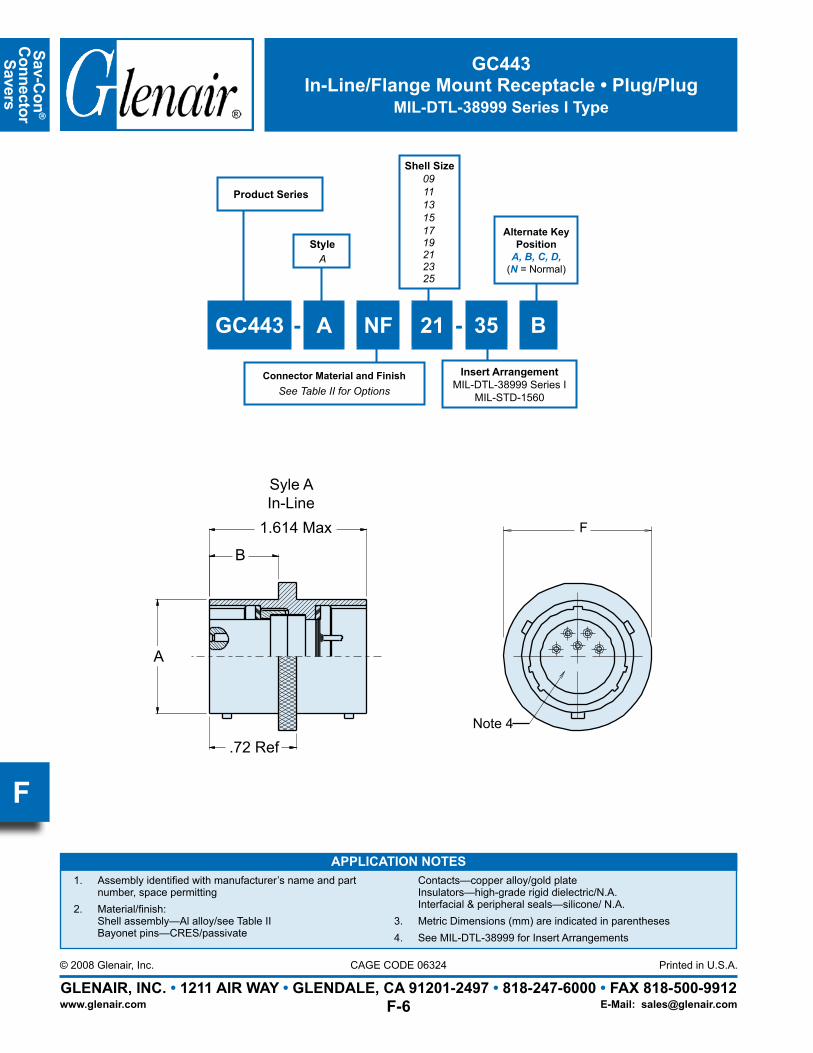
GC443In-Line/Flange Mount Receptacle • Plug/Plug
MIL-DTL-38999 Series I Type
APPLICATION NOTESAssembly identified with manufacturer’s name and part 1. number, space permittingMaterial/finish: 2. Shell assembly—Al alloy/see Table II Bayonet pins—CRES/passivate
Contacts—copper alloy/gold plate Insulators—high-grade rigid dielectric/N.A. Interfacial & peripheral seals—silicone/ N.A.Metric Dimensions (mm) are indicated in parentheses3. See MIL-DTL-38999 for Insert Arrangements4.
F
Note 4
.72 Ref
1.614 Max
B
A
Syle AIn-Line
Product Series
Connector Material and FinishSee Table II for Options
Shell Size091113151719212325
GC443 - A NF 21 - 35 B
StyleA
Alternate Key Position
A, B, C, D,(N = Normal)
Insert ArrangementMIL-DTL-38999 Series I
MIL-STD-1560
Page 24
Sav-
Con
®
Con
nect
or
Save
rs
GLENAIR, INC. • 1211 AIR WAY • GLENDALE, CA 91201-2497 • 818-247-6000 • FAX 818-500-9912Printed in U.S.A.
www.glenair.com
CAGE CODE 06324© 2008 Glenair, Inc.
E-Mail: [email protected]
F
GC443In-Line/Flange Mount Receptacle • Plug/Plug
MIL-DTL-38999 Series I Type
TABLE I: CONNECTOR DIMENSIONSSHELLSIZE
A DIAMAX
B DIAMAX
C +.010-.005(+0.3-0.1)
DDIM
E DIM±.020(0.5)
F DIAMAX
09 .573(14.6) .632(16.1) .128(3.3) .719(18.3) .938(23.8) .859(21.8)11 .701(17.8) .632(16.1) .128(3.3) .812(20.6) 1.031(26.2) .984(25.0)13 .851(21.6) .632(16.1) .128(3.3) .906(23.0) 1.125(28.6) 1.156(29.4)15 .976(24.8) .632(16.1) .128(3.3) .969(24.6) 1.219(31.0) 1.281(32.5)17 1.101(28.0) .632(16.1) .128(3.3) 1.062(27.0) 1.312(33.3) 1.406(35.7)19 1.208(30.7) .632(16.1) .128(3.3) 1.156(29.4) 1.438(36.5) 1.516(38.5)21 1.333(33.9) .602(15.3) .147(3.7) 1.250(31.8) 1.562(39.7) 1.641(41.7)23 1.458(37.0) .602(15.3) .147(3.7) 1.375(34.9) 1.688(42.9) 1.766(44.9)25 1.583(40.2) .602(15.3) .147(3.7) 1.500(38.1) 1.812(46.0) 1.891(48.0)
TABLE II: SHELL FINISHESPlating Code Material Finish
M Aluminum Electroless NickelB Aluminum Cad Plate, Olive Drab
NF Aluminum Cadmium Plate Olive Drab over Electroless Nickel
NC Aluminum Zinc-Cobalt
ZN Aluminum Olive Drab Zinc-Nickel
MT Aluminum Ni-PTFE 1000 Hour GreyTM (Nickel Flourocarbon Polymer)
Page 25
Sav-Con
®
Connector Savers
GLENAIR, INC. • 1211 AIR WAY • GLENDALE, CA 91201-2497 • 818-247-6000 • FAX 818-500-9912Printed in U.S.A.
www.glenair.com
CAGE CODE 06324© 2008 Glenair, Inc.
E-Mail: [email protected]
F
B
EMI Ground Spring(Standard)
Interfacial Seal
RECEPTACLE END
LOCK RING(Standard)
PLUG ENDA
1.20(30.5)MAX
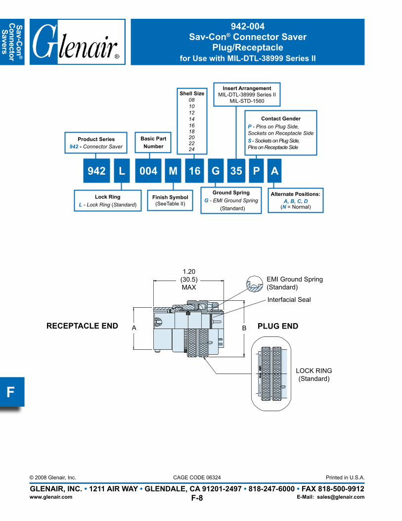
942-004Sav-Con® Connector Saver
Plug/Receptaclefor Use with MIL-DTL-38999 Series II
Shell Size081012141618202224
942 L 004 M 16 G 35 P A
Alternate Positions:A, B, C, D
(N = Normal)
Product Series942 - Connector Saver
Contact GenderP - Pins on Plug Side,Sockets on Receptacle SideS - Sockets on Plug Side,Pins on Receptacle Side
Lock RingL - Lock Ring (Standard)
Ground SpringG - EMI Ground Spring
(Standard)
Finish Symbol(SeeTable II)
Basic PartNumber
Insert ArrangementMIL-DTL-38999 Series II
MIL-STD-1560
Page 26
Sav-
Con
®
Con
nect
or
Save
rs
GLENAIR, INC. • 1211 AIR WAY • GLENDALE, CA 91201-2497 • 818-247-6000 • FAX 818-500-9912Printed in U.S.A.
www.glenair.com
CAGE CODE 06324© 2008 Glenair, Inc.
E-Mail: [email protected]
F
942-004Sav-Con® Connector Saver
Plug/Receptaclefor Use with MIL-DTL-38999 Series II
TABLE I: CONNECTOR DIMENSIONSSHELLSIZE A MAX. B MAX.
08 .474 (12.0) .750 (19.1)10 .591 (15.0) .859 (21.8)12 .751 (19.1) 1.031 (26.2)14 .875 (22.2) 1.156 (29.4)16 1.001 (25.4) 1.281 (32.5)18 1.126 (28.6) 1.406 (35.7)20 1.251 (31.8) 1.531 (38.9)22 1.376 (35.0) 1.656 (42.1)24 1.501 (38.1) 1.777 (45.1)
SERIES II: ALTERNATE KEYWAY POSITIONSSHELLSIZE N° A° B° C° D°
08 100 82 -- -- 118
10 100 86 72 128 114
12 100 80 68 132 120
14 100 79 66 134 121
16 100 82 70 130 118
18 100 82 70 130 118
20 100 82 70 130 118
22 100 85 74 126 115
24 100 85 74 125 115
FACE VIEWRECEPTACLE
CD
NA
B
CL28° 37°
100°
TABLE II: SHELL FINISHESPlating Code Material Finish
M Aluminum Electroless NickelB Aluminum Cad Plate, Olive Drab
NF Aluminum Cadmium Plate Olive Drab over Electroless Nickel
NC Aluminum Zinc-Cobalt
ZN Aluminum Olive Drab Zinc-Nickel
MT Aluminum Ni-PTFE 1000 Hour GreyTM (Nickel Flourocarbon Polymer)
Page 27
Sav-Con
®
Connector Savers
GLENAIR, INC. • 1211 AIR WAY • GLENDALE, CA 91201-2497 • 818-247-6000 • FAX 818-500-9912Printed in U.S.A.
www.glenair.com
CAGE CODE 06324© 2008 Glenair, Inc.
E-Mail: [email protected]
F
TABLE I: CONNECTOR DIMENSIONS
SHELLSIZE
SHELLSIZE
CODE
A THREAD0.1P-0.3L-TS-2
B DIAMAX
09 A .6250 .859
11 B .7500 .969
13 C .8750 1.141
15 D 1.0000 1.266
17 E 1.1875 1.391
19 F 1.2500 1.500
21 G 1.3750 1.625
23 H 1.5000 1.750
25 J 1.6250 1.875
942-005Sav-Con® Connector Saver
Plug/Receptaclefor Use with MIL-DTL-38999 Series III
A ThreadClass 2A
Full MateRed Indicator
Band 1.500 (38.1)
B
Knurl Style Mfr Option
Set Screws to Lock Coupling
Ground Spring(Standard)
A ThreadClass 2B
APPLICATION NOTES
Assembly features straight-thru double ended socket contacts. 1. Power to a given contact on one end will result in power to contact directly opposite regardless of identification.Metric dimensions (mm) are indicated in parentheses.2. Material/finish: 3. Barrel/shell, coupling nut, lock ring—Al alloy
Contacts, grounding ring—Copper Al alloy/gold plate Detent spring—Corrosion resistant material Retaining device—CRES/passivate O-ring, interfacial & peripheral seals—Fluorosilicone/N.A. Insulators—High grade rigid dielectric/ N.A.
Connector Material and FinishSee Table II
Shell SizeCode
942 - 005 NF B - 35 P B
Basic Number
P - Pins, plug sideS - Sockets, plug side
Alternate positions:A, B, C, D, E(N = Normal)
Product Series942 - Connector Saver
Insert ArrangementMIL-DTL-38999 Series III
MIL-STD-1560
Page 28
Sav-
Con
®
Con
nect
or
Save
rs
GLENAIR, INC. • 1211 AIR WAY • GLENDALE, CA 91201-2497 • 818-247-6000 • FAX 818-500-9912Printed in U.S.A.
www.glenair.com
CAGE CODE 06324© 2008 Glenair, Inc.
E-Mail: [email protected]
F
942-005Sav-Con® Connector Saver
Plug/Receptaclefor Use with MIL-DTL-38999 Series III
SERIES III: ALTERNATE KEYWAY POSITIONS
Shell SizeCode
Shell SizeRef
AlternateKeywayCode
AR° BR° CR° DR°
A 09
N 105 140 215 265A 102 132 248 320B 80 118 230 312C 35 140 205 275D 64 155 234 304E 91 131 197 240
BCD
111315
N 95 141 208 236A 113 156 182 292B 90 145 195 252C 53 156 220 255D 119 146 176 298E 51 141 184 242
EF
1719
N 80 142 196 293A 135 170 200 310B 49 169 200 244C 66 140 200 257D 62 145 180 280E 79 153 197 272
GHJ
212325
N 80 142 196 293A 135 170 200 310B 49 169 200 244C 66 140 200 257D 62 145 180 280E 79 153 197 272
DR
CR
BRAR
FACE VIEWRECEPTACLE
CLTABLE II: SHELL FINISHES
Plating Code Material Finish
M Aluminum Electroless NickelB Aluminum Cad Plate, Olive Drab
NF Aluminum Cadmium Plate Olive Drab over Electroless Nickel
NC Aluminum Zinc-Cobalt
ZN Aluminum Olive Drab Zinc-Nickel
MT Aluminum Ni-PTFE 1000 Hour GreyTM (Nickel Flourocarbon Polymer)
Page 29
Sav-Con
®
Connector Savers
GLENAIR, INC. • 1211 AIR WAY • GLENDALE, CA 91201-2497 • 818-247-6000 • FAX 818-500-9912Printed in U.S.A.
www.glenair.com
CAGE CODE 06324© 2008 Glenair, Inc.
E-Mail: [email protected]
F
TABLE I: CONNECTORDIMENSIONS
SHELLSIZE
A THREAD0.1 P-0.3L-TS-2
B DIAMAX
09 0.6250 .859(21.8)
11 0.7500 .969(24.6)
13 0.8750 1.141(29.0)
15 1.0000 1.266(32.2)
17 1.1875 1.391(35.3)
19 1.2500 1.500(38.1)
21 1.3750 1.625(41.3)
23 1.5000 1.750(44.5)
25 1.6250 1.875(47.6)
APPLICATION NOTESAssembly features straight-thru double-ended contacts, 1. power to a given contact on one end will result in power to contact directly opposite, regardless of identification.Symetrical layout only, Consult factory for available insert 2. arrangements.Metric dimensions (mm) are indicated in parentheses.3.
Material/finish: 4. Barrel, adapter, junction nuts, coupling nuts—Al alloy/see Table I. Insulators—High grade rigid dielectric/N.A. Contacts—Copper alloy/gold plate
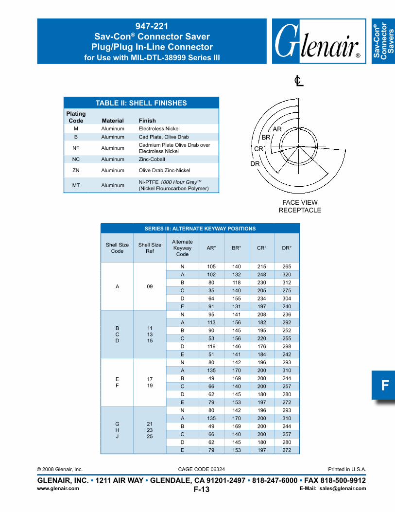
947-221Sav-Con® Connector Saver
Plug/Plug In-Line Connectorfor Use with MIL-DTL-38999 Series III
Connector Material and FinishSee Table II
Shell Size
947 - 221 NF 15 - 35 PP B
Basic Number
PP - Pin/Pin ContactsSS - Socket/Socket ContactsPS - Pin/Socket Contacts
Alternate positions:A, B, C, D, E(N = Normal)
Product Series947 - Connector Saver
2.300 (58.4)Max
B MaxTyp
A Thread Typ
Socket Interface
Pin Interface
Ground Spring(Standard)
Insert ArrangementMIL-DTL-38999 Series III
MIL-STD-1560
Page 30
Sav-
Con
®
Con
nect
or
Save
rs
GLENAIR, INC. • 1211 AIR WAY • GLENDALE, CA 91201-2497 • 818-247-6000 • FAX 818-500-9912Printed in U.S.A.
www.glenair.com
CAGE CODE 06324© 2008 Glenair, Inc.
E-Mail: [email protected]
F
947-221Sav-Con® Connector Saver
Plug/Plug In-Line Connectorfor Use with MIL-DTL-38999 Series III
SERIES III: ALTERNATE KEYWAY POSITIONS
Shell SizeCode
Shell SizeRef
AlternateKeywayCode
AR° BR° CR° DR°
A 09
N 105 140 215 265A 102 132 248 320B 80 118 230 312C 35 140 205 275D 64 155 234 304E 91 131 197 240
BCD
111315
N 95 141 208 236A 113 156 182 292B 90 145 195 252C 53 156 220 255D 119 146 176 298E 51 141 184 242
EF
1719
N 80 142 196 293A 135 170 200 310B 49 169 200 244C 66 140 200 257D 62 145 180 280E 79 153 197 272
GHJ
212325
N 80 142 196 293A 135 170 200 310B 49 169 200 244C 66 140 200 257D 62 145 180 280E 79 153 197 272
DR
CR
BRAR
FACE VIEWRECEPTACLE
CLTABLE II: SHELL FINISHES
Plating Code Material Finish
M Aluminum Electroless NickelB Aluminum Cad Plate, Olive Drab
NF Aluminum Cadmium Plate Olive Drab over Electroless Nickel
NC Aluminum Zinc-Cobalt
ZN Aluminum Olive Drab Zinc-Nickel
MT Aluminum Ni-PTFE 1000 Hour GreyTM (Nickel Flourocarbon Polymer)
Page 31
Sav-Con
®
Connector Savers
GLENAIR, INC. • 1211 AIR WAY • GLENDALE, CA 91201-2497 • 818-247-6000 • FAX 818-500-9912Printed in U.S.A.
www.glenair.com
CAGE CODE 06324© 2008 Glenair, Inc.
E-Mail: [email protected]
F APPLICATION NOTES
For pin/pin and skt/skt symmetrical layouts only. Consult factory for 1. available insert arrangements.Power to a given contact on one end will result in power to the contact 2. directly opposite, regardless of identification marking.Metric dimensions (mm) are indicated in parentheses.3.
Material/finish: 4. Shell assembly—Al alloy/see Table II Contacts—Copper alloy/gold plate Insulators—High-grade rigid dielectric/ N.A. Seals—Silicone/ N.A
TABLE I: CONNECTOR DIMENSIONS
SHELLSIZE C THREAD Ø D
MAX09 .625-1P-.3L-2A .859
11 .750-1P-.3L-2A .984
13 .875-1P-.3L-2A 1.156
15 1.000-1P-.3L-2A 1.281
17 1.187-1P-.3L-2A 1.406
19 1.250-1P-.3L-2A 1.516
21 1.375-1P-.3L-2A 1.641
23 1.500-1P-.3L-2A 1.766
25 1.625-1P-.3L-2A 1.891“C” Threads
1.530 (38.9)Max.620
(15.8)Typ
See MIL-STD-1560for insert arrangements
Ø D
947-139Sav-Con® Connector Saver
In-Line Connectorfor Use with MIL-DTL-38999 Series III
Connector Material and FinishSee Table II for Options
Shell Size
947 - 139 NF 21 - 35 SE SN
Basic Number
Side “A”S - SocketsP - Pin ContactsAlternate Positions per MIL-DTL-38999:A, B, C, D, E or N
Product Series947 - Connector Saver
Insert ArrangementMIL-DTL-38999 Series III
MIL-STD-1560
Side “B”S - SocketsP - Pin ContactsAlternate Positions per MIL-DTL-38999:A, B, C, D, E or N
Page 32
Sav-
Con
®
Con
nect
or
Save
rs
GLENAIR, INC. • 1211 AIR WAY • GLENDALE, CA 91201-2497 • 818-247-6000 • FAX 818-500-9912Printed in U.S.A.
www.glenair.com
CAGE CODE 06324© 2008 Glenair, Inc.
E-Mail: [email protected]
F
947-139Sav-Con® Connector Saver
Pin/Pin or Socket/Socket In-Line Connectorfor Use with MIL-DTL-38999 Series III
SERIES III: ALTERNATE KEYWAY POSITIONS
Shell SizeCode
Shell SizeRef
AlternateKeywayCode
AR° BR° CR° DR°
A 09
N 105 140 215 265A 102 132 248 320B 80 118 230 312C 35 140 205 275D 64 155 234 304E 91 131 197 240
BCD
111315
N 95 141 208 236A 113 156 182 292B 90 145 195 252C 53 156 220 255D 119 146 176 298E 51 141 184 242
EF
1719
N 80 142 196 293A 135 170 200 310B 49 169 200 244C 66 140 200 257D 62 145 180 280E 79 153 197 272
GHJ
212325
N 80 142 196 293A 135 170 200 310B 49 169 200 244C 66 140 200 257D 62 145 180 280E 79 153 197 272
DR
CR
BRAR
FACE VIEWRECEPTACLE
CLTABLE II: SHELL FINISHES
Plating Code Material Finish
M Aluminum Electroless NickelB Aluminum Cad Plate, Olive Drab
NF Aluminum Cadmium Plate Olive Drab over Electroless Nickel
NC Aluminum Zinc-Cobalt
ZN Aluminum Olive Drab Zinc-Nickel
MT Aluminum Ni-PTFE 1000 Hour GreyTM (Nickel Flourocarbon Polymer)
Page 33
Sav-Con
®
Connector Savers
GLENAIR, INC. • 1211 AIR WAY • GLENDALE, CA 91201-2497 • 818-247-6000 • FAX 818-500-9912Printed in U.S.A.
www.glenair.com
CAGE CODE 06324© 2008 Glenair, Inc.
E-Mail: [email protected]
F
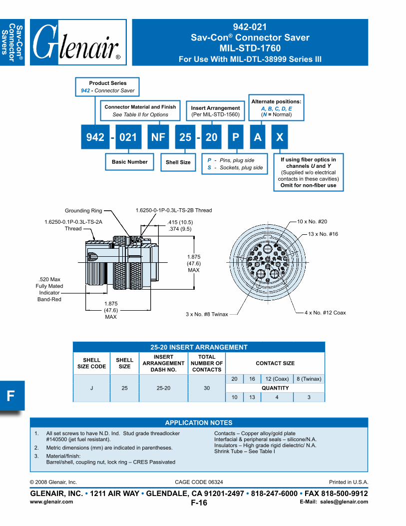
1.875(47.6)MAX
1.6250-0-1P-0.3L-TS-2B Thread
1.6250-0.1P-0.3L-TS-2A Thread
.520 MaxFully Mated
IndicatorBand-Red
1.875(47.6)MAX
Grounding Ring
.415 (10.5).374 (9.5)
3 x No. #8 Twinax 4 x No. #12 Coax
10 x No. #20
13 x No. #16
25-20 INSERT ARRANGEMENT
SHELLSIZE CODE
SHELL SIZE
INSERTARRANGEMENT
DASH NO.
TOTAL NUMBER OF CONTACTS
CONTACT SIZE
J 25 25-20 30
20 16 12 (Coax) 8 (Twinax)
QUANTITY10 13 4 3
APPLICATION NOTESAll set screws to have N.D. Ind. Stud grade threadlocker 1. #140500 (jet fuel resistant).Metric dimensions (mm) are indicated in parentheses.2. Material/finish: 3. Barrel/shell, coupling nut, lock ring – CRES Passivated
Contacts – Copper alloy/gold plate Interfacial & peripheral seals – silicone/N.A. Insulators – High grade rigid dielectric/ N.A. Shrink Tube – See Table I
942-021Sav-Con® Connector Saver
MIL-STD-1760For Use With MIL-DTL-38999 Series III
Insert Arrangement(Per MIL-STD-1560)
If using fiber optics in channels U and Y
(Supplied w/o electrical contacts in these cavities)Omit for non-fiber use
Connector Material and FinishSee Table II for Options
Shell Size
942 - 021 NF 25 - 20 P A X
Basic Number
Product Series942 - Connector Saver
P - Pins, plug sideS - Sockets, plug side
Alternate positions:A, B, C, D, E(N = Normal)
Page 34
Sav-
Con
®
Con
nect
or
Save
rs
GLENAIR, INC. • 1211 AIR WAY • GLENDALE, CA 91201-2497 • 818-247-6000 • FAX 818-500-9912Printed in U.S.A.
www.glenair.com
CAGE CODE 06324© 2008 Glenair, Inc.
E-Mail: [email protected]
F
942-021Sav-Con® Connector Saver
MIL-STD-1760For Use With MIL-DTL-38999 Series III
SERIES III: ALTERNATE KEYWAY POSITIONS
Shell SizeCode
Shell SizeRef
AlternateKeywayCode
AR° BR° CR° DR°
J 25
N 80 142 196 293A 135 170 200 310B 49 169 200 244C 66 140 200 257D 62 145 180 280E 79 153 197 272
DR
CR
BRAR
FACE VIEWRECEPTACLE
CL
Page 35
Glenair MIL-DTL-38999 TypeEMI/RFI Connectors and Accessories
SECTION G TABLE OF CONTENTSGLENAIR MIL-DTL-38999 TYPE EMI/RFI CONNECTORS AND ACCESSORIES:
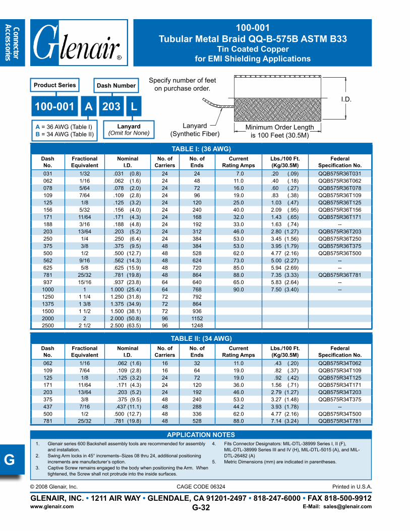
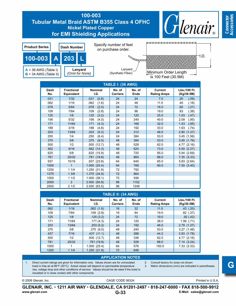
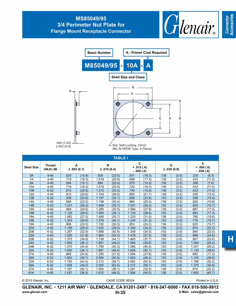
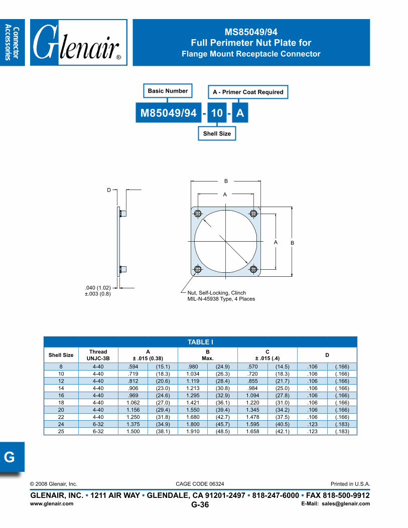
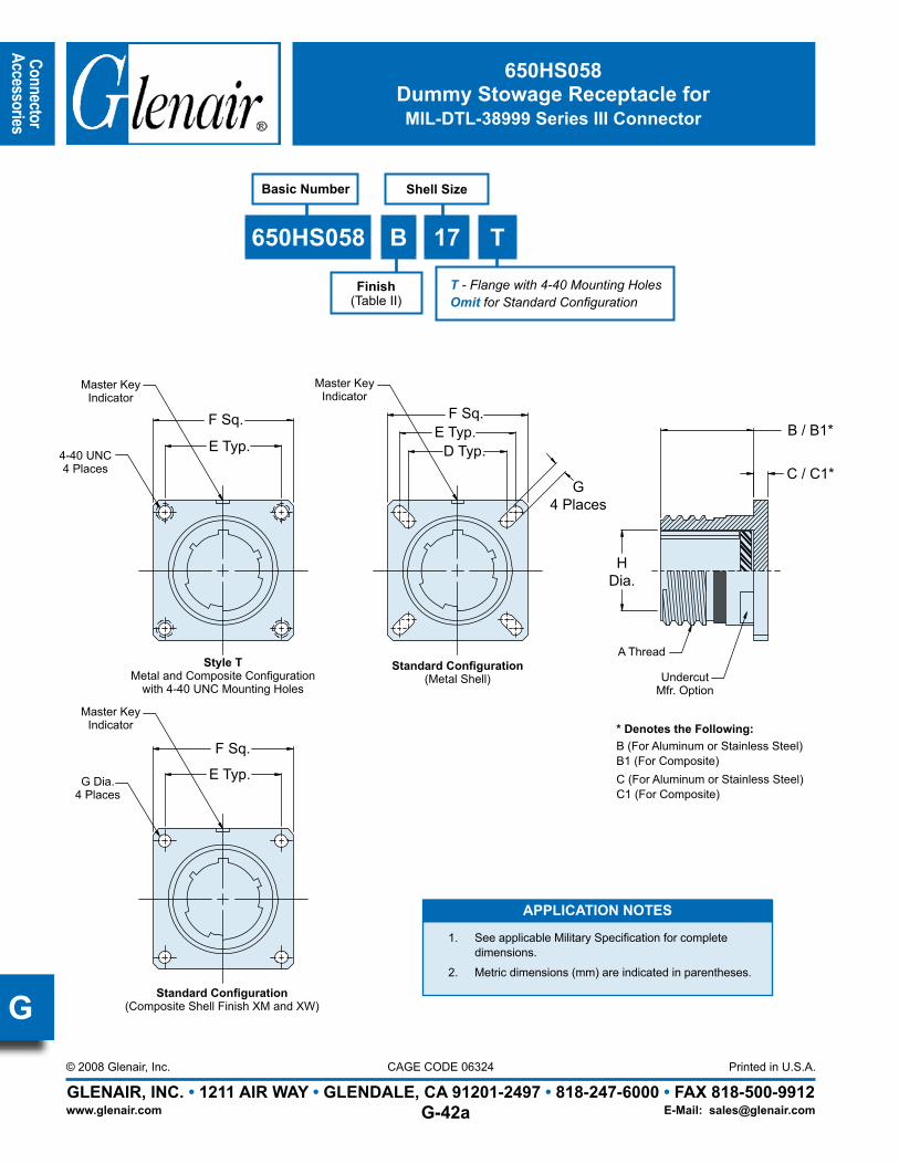
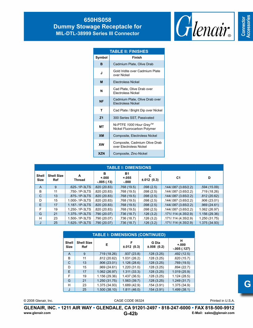
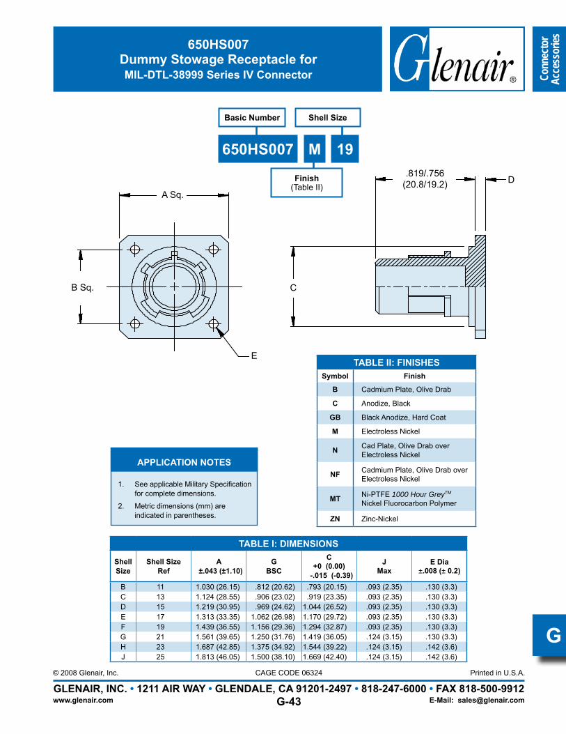
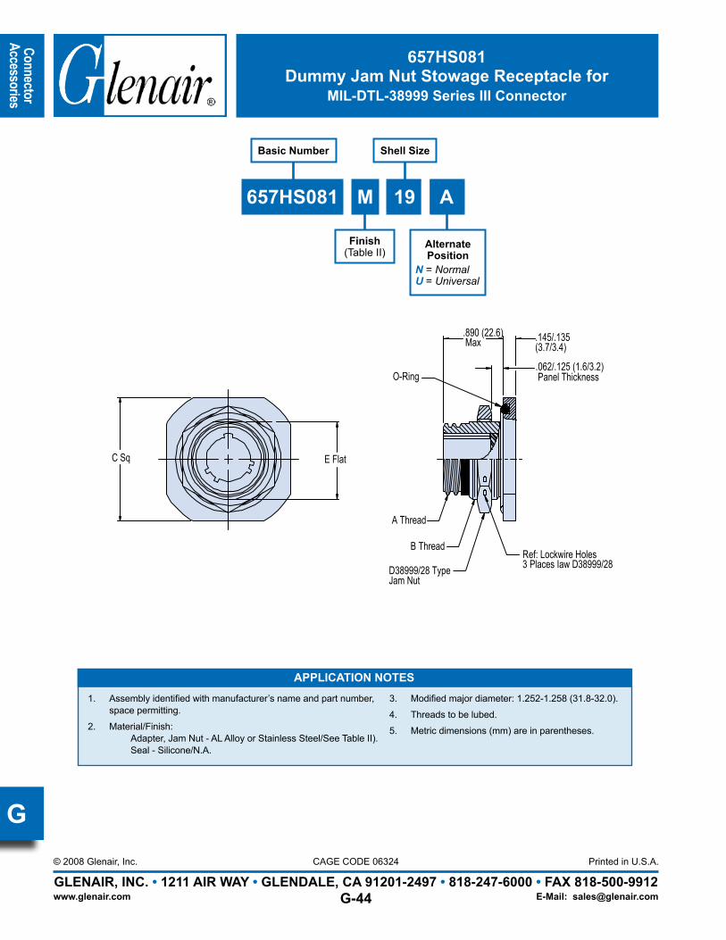
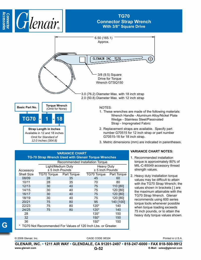
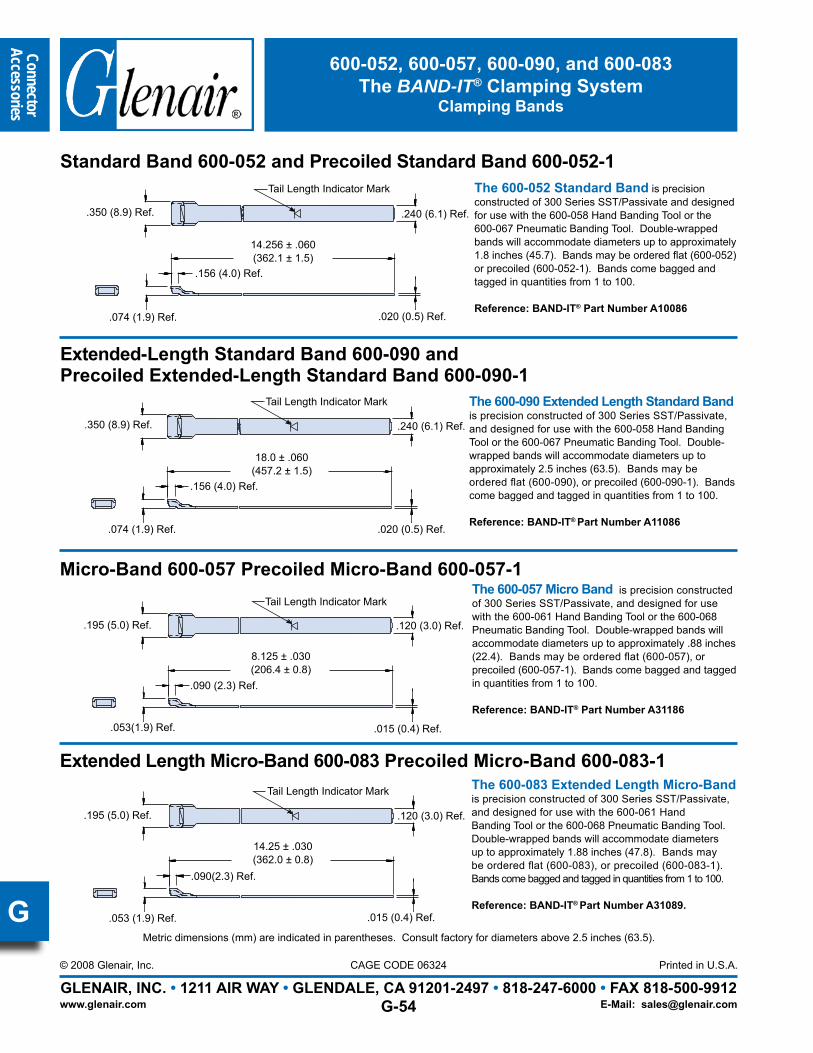
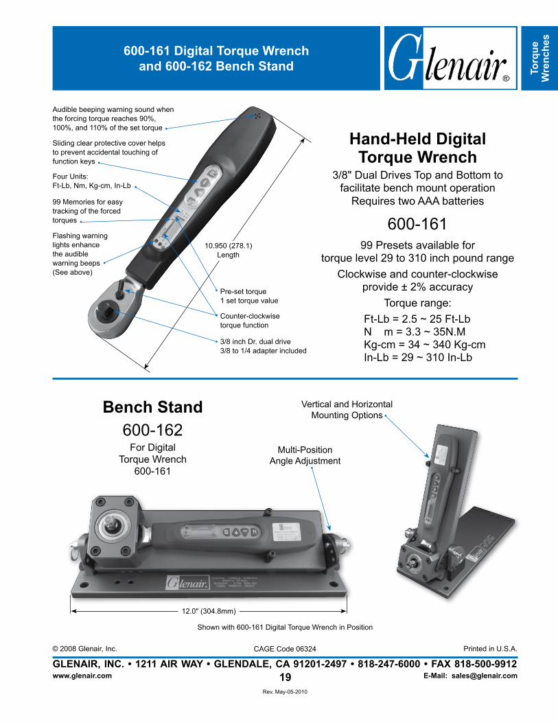
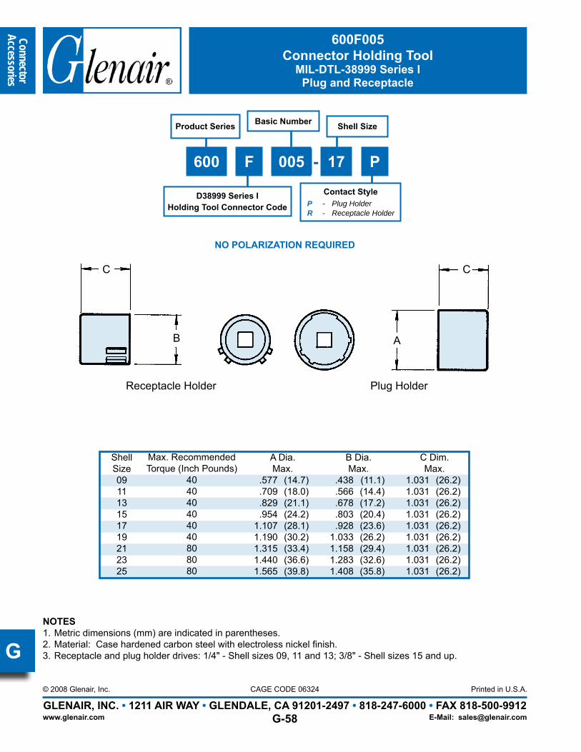
Glenair MIL-DTL-38999 Type Power Connector Product Features......................................................G-1Glenair MIL-DTL-38999 Type Backshells and Accessories Selection Guide..................................G-2Glenair D38999 Type Backshell Interface Dimensions........................................................................G-4 Shrink Boot Reference Information......................................................................................................G-5770-001 Heat-Shrinkable Molded Boots..............................................................................................G-6310-001 O-Ring Sealed Shrink Boot Adapter......................................................................................G-8319-064 Composite Swing-Arm Strain Relief with Nickel/Copper EMI/RFI Shield Sock..................G-10319-065 Composite Swing-Arm Strain Relief with Composite EMI/RFI Shield Sock........................G-12Swing-Arm Assembly Instructions....................................................................................................G-14380-107 EMI/RFI Split-Shell Non-Environmental Backshell with Strain Relief..........................................G-16380-115 EMI/RFI Low Profile Non-Environmental Backshell with Strain Relief.......................................G-18440-069 EMI/RFI Shrink Boot Banding Adapter..................................................................................G-20447-425 EMI/RFI Non-Environmental Band-In-A-Can Backshell with Strain-Relief.........................G-22620-048 Strain Relief Clamp, Straight and 90°................................................................................G-24620-049 Strain Relief Clamp, 45°......................................................................................................G-25627-122 Composite Swing-Arm Strain Relief....................................................................................G-26687-207 Composite MIL-C-85049/93 Banding Split-Ring................................................................G-28103-026 and -027 AmberStrand® Composite EMI/RFI Braid............................................................G-29100-001 Tubular Metal Braid QQ-B-575B ASTM B33 Tin Coated Copper......................................G-30100-003 Tubular Metal Braid ASTM B355 Class 4 OFHC Nickel Plated Copper........................G-31930-001 Conductive Gasket for Flange Mount Series III Receptacle Connector...............................G-32MS85049/94 Full Perimeter Nut Plate.............................................................................................G-34MS85049/95 3/4 Perimeter Nut Plate.............................................................................................G-35MS85049/96 1/4 Perimeter Nut Plate.............................................................................................G-36650FS001 Series I Dummy Stowage Receptacle...............................................................................G-38650FS002 Series II Dummy Stowage Receptacle...............................................................................G-39650HS058 Series III Dummy Stowage Receptacle..............................................................................G-40650HS007 Dummy Stowage Receptacle for MIL-DTL-38999 Series IV Connectors.......................G-41660-012 (Plug), 660-013 (Receptacle), 661-002 (EMI Receptacle) Series I Protective Covers........G-42660-014 (Plug), 660-015 (Receptacle), 661-003 (EMI Receptacle) Series II Protective Covers........G-4460-023 (Plug), 660-024 (Receptacle) Series III Protective Covers................................................G-4660-031 (Plug), 660-032 (Receptacle) Series IV Protective Covers.................................................G-48TG70 Strap Wrench with 3/8” Square Drive...................................................................................G-50BAND-IT® Shield Termination Clamping System....................................................................G-51 - G-53 600-004 and 600-007 Bench Mount and Hand Held Torque Wrenches....................................G-54600-161 Hand Held Digital Torque Wrench and 600-162 Bench Stand............................................G55MIL-DTL-38999 Series I, II, III and IV Connector Holding Tools.........................................G-56 - G-62600-091 and 600-157 Composite Hex Coupling Wrench.......................................................G-63 - G-64
Page 36
Conn
ecto
rAc
cess
ories
GLENAIR, INC. • 1211 AIR WAY • GLENDALE, CA 91201-2497 • 818-247-6000 • FAX 818-500-9912Printed in U.S.A.
www.glenair.com
CAGE CODE 06324© 2008 Glenair, Inc.
E-Mail: [email protected]
G
Because the Art of Interconnect Cable Design Calls for More Technology Than Just a ConnectorBackshells: A Part of Every Well-Designed Cable Harness and Assembly
Glenair understands that the management of EMI, environmental damage and mechanical stress factors in high-reliability cable assemblies usually requires the incorpoartion if various connector backshells and accessories. We offer thousands of EMI management products, cable-sealing backshells, protective covers, strain-relief devices and other essential accessories. In this section of the book we’ve organized a small selection of some of the most practical devices used in Mil-Aero cabling. We’ve chosen the most popular and useful products for assemblies built around the D38999 family.
MIL-DTL-38999 Connector Accessoriesand Assembly Tools
could include both a suitable EMI filtering device but also an appropriate selection of accessories such as shield termination backshells, EMI gaskets and conductive shielding.
For environmental protection, Glenair offers both standard shrink-boot products as well as more robust cable-sealing backshells and protective covers. For mechanical protection we offer a broad range of strain-relief backshells to prevent damage to the conductor-to-contact intertface. Whatever your requirement, Glenair has both the connectors, and the accessories, to put
Glenair is the world’s largest supplier of EMI Shielding backshells, cable sealing backshells and strain-relief devices. Over 65,000 part numbers are in stock and ready for same-day shipment
This section includes just a small selection of the most practical connector accessories designed for use on D38999 connectors
Glenair offers both AS85049 QPL solutions as well as a broad selection of commercial designs for every electrical, mechanical and environmental requirement.
For example, effective shielding of avionic devices equipped with D38999 signal connectors must anticipate both “radiated susceptibility” (the degree to which outside interference affects the reliable functioning of equipment) and “radiated emissions” (the extent to which the device itself creates electromagnetic waves which can affect its function). In both cases, managing the interference
together a finished cable design that meets all the requirements of your application.
NOTE: Catalog contents are accurate to the best of our ability when we go to print. When errors or mistakes are brought to our attention, corrected content is posted immediately to our website: www.glenair.com.
Page 37
ConnectorAccessories
GLENAIR, INC. • 1211 AIR WAY • GLENDALE, CA 91201-2497 • 818-247-6000 • FAX 818-500-9912Printed in U.S.A.
www.glenair.com
CAGE CODE 06324© 2008 Glenair, Inc.
E-Mail: [email protected]
G
Military Standard Circular Connector Accessories
Milt
ary
Con
nect
orSp
ecifi
catio
ns
Shrink Boot Adapters
NonEnvironmental Strain ReliefBackshells
EMI/RFINon-
EnvironmentalBackshells
EMI/RFIEnvironmental
BackshellsBanding
Backshells
MIL
-C-3
8999
Serie
s I
M85049/62 Straight
M85049/29 Straight
M85049/36 Straight
M85049/37 90°
M85049/17 Straight
M85049/76 90°
M85049/77 45°
M85049/85 Straight
M85049/86 45°
M85049/87 90°
MIL
-C-3
8999
Serie
s II
M85049/62 Straight
M85049/29 Straight
M85049/36 Straight
M85049/37 90°
M85049/17 Straight
M85049/76 90°
M85049/77 45°
M85049/85 Straight
M85049/86 45°
M85049/87 90°
MIL
-C-3
8999
Serie
s III
M85049/69 Straight
M85049/21 Straight
M85049/19 Straight
M85049/18 Straight
M85049/78 45°
M85049/79 90°
M85049/88 Straight
M85049/89 45°
M85049/90 90°
MIL
-C-3
8999
Serie
s IV
M85049/69 Straight
M85049/21 Straight
M85049/19 Straight
M85049/18 Straight
M85049/78 45°
M85049/79 90°
M85049/88 Straight
M85049/89 45°
M85049/90 90°
MIL-DTL-38999Backshells and Accessories Selection Guide
Page 38
Conn
ecto
rAc
cess
ories
GLENAIR, INC. • 1211 AIR WAY • GLENDALE, CA 91201-2497 • 818-247-6000 • FAX 818-500-9912Printed in U.S.A.
www.glenair.com
CAGE CODE 06324© 2008 Glenair, Inc.
E-Mail: [email protected]
G
Military Standard Circular Connector Accessories
Qwick-Ty Strain Reliefs Strain Reliefs Dummy
StowageRecep-tacles
Protective Plug
Covers
ProtectiveReceptacle
Covers Miltary
Connector
Specifications
Non-Self Locking Self Locking Non-Self Locking Self Locking
M85049/56 straight
M85049/57 45°
M85049/58 90°
No Ground LugM85049/56S
StraightM85049/57S
45°W/ Ground LugM85049/56G
StraightM85049/57G
45°
M85049/45 StraightM85049/46 90°
M85049/47 (MS27507) 90°
M85049/49 (MS27506) Straight
M85049/47S 90°
M85049/49S Straight
M38999/9 MS27501 MS27502
MIL-C
-38999Series I
M85049/56 straight
M85049/57 45°
M85049/58 90°
No Ground LugM85049/56S
StraightM85049/57S
45°W/ Ground LugM85049/56G
StraightM85049/57G
45°
M85049/45 StraightM85049/46 90°
M85049/47 (MS27507) 90°
M85049/49 (MS27506) Straight
M85049/47S 90°
M85049/49S Straight
M38999/10 MS27510 MS27511
MIL-C
-38999Series II
M85049/15 45°
M85049/16 90°
N/A
M85049/38 StraightM85049/39 90°
M85049/91 StraightM85049/92 90°
M85049/38S Straight
M85049/39S 90°
M38999/22 D38999/32Threaded
D38999/33Threaded
MIL-C
-38999Series III
M85049/15 45°
M85049/16 90°
M85049/15 45°
M85049/16 90°
M85049/38 StraightM85049/39 90°
M85049/91 StraightM85049/92 90°
M85049/38S Straight
M85049/39S 90°
M38999/50 N/A N/A
MIL-C
-38999Series IV
MIL-DTL-38999Backshells and Accessories Selection Guide
Page 39
ConnectorAccessories
GLENAIR, INC. • 1211 AIR WAY • GLENDALE, CA 91201-2497 • 818-247-6000 • FAX 818-500-9912Printed in U.S.A.
www.glenair.com
CAGE CODE 06324© 2008 Glenair, Inc.
E-Mail: [email protected]
G
Table I:Backshell Interface Dimensions
TABLE I: BACKSHELL INTERFACE DIMENSIONSCONNECTOR DESIGNATOR A THREAD
REFERENCEB DIAMAX
C DIAMAX
D DIAMAX
E DIAMAXF H
08 [9] 7/16 – 28 UNEF .590 (15.) .650 (16.5) .770 (19.6) .690 (17.5)
09 [A] M12 x 1 – 6H .650 (16.5) .770 (19.6) .940 (24.8)
10 [11] 9/16 – 24 UNEF .720 (18.3) .770 (19.6) .890 (22.6) .820 (20.8)
11 [B] M15 x 1 – 6H .770 (19.6) .820 (20.8) 1.060 (26.9)
12 [13] 11/16 – 24 UNEF .840 (21.3) .890 (22.6) 1.020 (25.9) .940 (23.8)
13 [C] M18 x 1 – 6H .890 (22.6) .940 (23.9) 1.170 (29.7)
14 [15] 13/16 – 20 UNEF .970 (24.6) 1.020 (29.2) 1.150 (29.2) 1.060 (26.9)
15 [D] M22 x 1 – 6H 1.030 (26.2) 1.070 (26.2) 1.290 (32.7)
16 [17] 15/16 – 20 UNEF 1.090 (27.7) 1.150 (29.2) 1.260 (32.0) 1.170 (29.7)
17 [E] M25 x 1 – 6H 1.150 (29.2) 1.210 (30.7) 1.420 (36.1)
18 [19] 1 1/16 – 18 UNEF 1.220 (31.0) 1.230 (31.2) 1.400 (35.6) 1.290 (32.7)
19 [F] M28 x 1 – 6H 1.280 (32.5) 1.360 (34.5) 1.540 (39.1)
20 [21] 1 3/16 – 18 UNEF 1.340 (34.0) 1.360 (34.5 1.530 (38.9) 1.420 (36.0)
21 [G] M31 x 1 – 6H 1.410 (35.8) 1.480 (37.6) 1.670 (42.4)
22 [23] 1 5/16 – 18 UNEF 1.470 (37.3 1.480 (37.6) 1.600 (40.6) 1.540 (39.1)
23 [H] M34 x 1 - 6H 1.530 (38.9) 1.600 (40.6) 2.010 (51.1)
24 [25] 1 7/16 – 18 UNEF 1.590 (40.4) 1.730 (43.9) 1.940 (49.3) 1.660 (42.2)
25 [J] M37 x 1 – 6H 1.660 (42.2) 1.700 (43.2) 2.120 (53.8)
Page 40
Conn
ecto
rAc
cess
ories
GLENAIR, INC. • 1211 AIR WAY • GLENDALE, CA 91201-2497 • 818-247-6000 • FAX 818-500-9912Printed in U.S.A.
www.glenair.com
CAGE CODE 06324© 2010 Glenair, Inc.
E-Mail: [email protected]
G
770-001Shrink Boot
Heat Shrink Molded Part
APPLICATION NOTES1. Material: Fluid resistant elastomer - Glenair Material Type 1.2. When the minimum number of conductors are used, wire bundle/cable may require build-up to B2 max.3. Sizes 00 to 02 do not contain eyelet.
TABLE I: STRAIGHT BOOT DIMENSIONS, BOOT AND SHELL SIZEBootSize
ShellSize
Ae DiaMin
Ce DiaMin
Ar DiaMax
at±30%
Cr DiaMax
ct±20%
CORef
PO±10%
P1±10%
RORef
00 5 .354 (9.0) .354 (9.0) .217 (5.5) .039 (1.0) .079 (2.0) .028 (0.7) .295 (7.5) .984 (25.0) N/A .551 (14.0)
01 5, 6 .472 (12.0) .472 (12.0) .276 (7.0) .043 (1.1) .118 (3.0) .028 (0.7) .295 (7.5) .984 (25.0) N/A .551 (14.0)
02 6, 7 .669 (17.0) .669 (17.0) .276 (7.0) .051 (1.3) .138 (3.5) .028 (0.7) .395 (10.0) 1.181 (30.0) N/A .728 (18.5)
03 8, 10 .945 (24.0) .945 (24.0) .413 (10.5) .063 (1.6) .197 (5.5) .035 (0.9) .395 (10.0) 1.496 (38.0) 1.024 (26.0) .748 (19.0)
04 11-16 1.181 (30.0) 1.181 (30.0) .551 (14.0) .071 (1.8) .236 (6.0) .039 (1.0) .630 (16.0) 2.165 (55.0) 1.693 (43.0) 1.181 (30.0)
05 16-17 1.260 (32.0) 1.260 (32.0) .709 (18.0) .071 (1.8) .276 (7.0) .047 (1.2) .748 (19.0) 2.638 (67.0) 1.850 (47.0) 1.299 (33.0)
06 17-21 1.417 (36.0) 1.417 (36.0) .886 (22.0) .079 (2.0) .335 (8.5) .047 (1.2) .787 (20.0) 3.150 (80.0) 2.362 (60.0) 1.575 (40.0)
07 21-23 1.693 (43.0) 1.693 (43.0) 1.102 (28.0) .087 (2.2) .394 (10.0) .051 (1.3) 1.142 (29.0) 3.898 (99.0) 3.150 (80.0) 2.165 (55.0)
08 25 2.362 (60.0) 2.362 (60.0) 1.378 (35.0) .130 (3.3) .591 (15.0) .063 (1.6) 1.575 (40.0) 5.118 (130.0) 4.331 (110.0) 1.969 (50.0)
Basic Part Number 001 - Lipped Boot with Eyelet002 - Short Lipped Boot with Eyelet003 - Lipped Boot004 - Short Lipped Boot005 - Non-Lipped Boot
Product SeriesPart Size
(See Table I)
770 - 001 A 1 00 W1
Angular FunctionA - 90°B - 45°S - Straight
Material1 - 150°C Compound 2025 Elastomeric Oil Resistant and Flame Retardant2 - Low Smoke Hazard Material3
Adhesive LinedW1 - Zero HalogenW2 - 80°C Hot MeltR - 150°C Epoxy Pre-Coat
(Omit for No Adhesive)
Ø.079 (2.0) Ref(See Note 3)
Ct
Ct
Recovered (-001)
Recovered (-002)
As Supplied As Supplied
Ce AeCe Ae
P0
R0
Cr
C0
Ar
At
Cr
C0
P1
Ar
At
S - StraightShrink Boot
Page 41
ConnectorAccessories
GLENAIR, INC. • 1211 AIR WAY • GLENDALE, CA 91201-2497 • 818-247-6000 • FAX 818-500-9912Printed in U.S.A.
www.glenair.com
CAGE CODE 06324© 2010 Glenair, Inc.
E-Mail: [email protected]
G
770-00190° Shrink Boot
Heat Shrink Molded Part
Ø.079 (2.0) Ref
R
AtAr
P
C0Ct
Cr
As Supplied
CeAe
Size 03 To 08Recovered
TABLE I: 90° BOOT DIMENSIONS, BOOT AND SHELL SIZEBootSize
ShellSize
Ae DiaMin
Ce DiaMin
Ar DiaMax
at±30%
Cr DiaMax
ct±20%
CORef
P±20%
RRef
03 9 .945 (24.0) .945 (24.0) .394 (10.0) .063 (1.6) .197 (5.0) .035 (0.9) .394 (10.0) .984 (25.0) .984 (25.0)
04 11-15 1.181 (30.0) 1.181 (30.0) .532 (13.5) .071 (1.8) .217 (5.5) .039 (1.0) .472 (12.0) 1.260 (32.0) 1.063 (27.0)
05 13-17 1.260 (32.0) 1.260 (32.0) .709 (18.0) .071 (1.8) .276 (7.0) .047 (1.2) .591 (15.0) 1.535 (39.0) 1.260 (32.0)
06 17-21 1.417 (36.0) 1.417 (36.0) .886 (22.0) .079 (2.0) .335 (8.5) .047 (1.2) .630 (16.0) 1.929 (49.0) 1.496 (38.0)
07 21-23 1.693 (43.0) 1.693 (43.0) 1.102 (28.0) .087 (2.2) .394 (10.0) .059 (1.5) .709 (18.0) 2.165 (55.0) 1.850 (47.0)
08 23-25 2.165 (55.0) 2.165 (55.0) 1.378 (35.0) .130 (3.3) .591 (15.0) .079 (2.0) 1.260 (32.0) 3.150 (80.0) 2.165 (55.0)
A - 90°Shrink Boot
Page 42
Conn
ecto
rAc
cess
ories
GLENAIR, INC. • 1211 AIR WAY • GLENDALE, CA 91201-2497 • 818-247-6000 • FAX 818-500-9912Printed in U.S.A.
www.glenair.com
CAGE CODE 06324© 2010 Glenair, Inc.
E-Mail: [email protected]
G
770-00145° Shrink Boot
Heat Shrink Molded Part
AeCe
RecoveredAs Supplied
RAt
Ar
Cr
Ct
P
Co
Ø.079 (2.0) Ref
TABLE I: 45° BOOT DIMENSIONS, BOOT AND SHELL SIZEBootSize
ShellSize
Ae DiaMin
Ce DiaMin
Ar DiaMax
at±30%
Cr DiaMax
ct±20%
CORef
P±10%
RRef
03 9 .945 (24.0) .945 (24.0) .413 (10.50) .063 (1.6) .157 (4.0) .035 (0.9) .315 (8.0) .748 (195.0) .500 (12.7)
04 11-15 1.181 (30.0) 1.181 (30.0) .551 (14.0) .071 (1.8) .236 (6.0) .039 (1.0) .354 (9.0) 1.180 (30.0) .748 (19.0)
05 13-17 1.260 (32.0) 1.260 (32.0) .709 (18.0) .079 (2.0) .276 (7.0) .071 (1.8) .591 (15.0) 1.378 (35.0) .984 (25.0)
06 17-21 1.417 (36.0) 1.417 (36.0) .886 (22.0) .079 (2.0) .335 (8.5) .071 (1.8) .709 (18.0) 1.575 (40.0) 1.260 (32.0)
07 21-23 1.693 (43.0) 1.693 (43.0) 1.102 (28.0) .087 (2.2) .394 (10.0) .079 (2.0) .709 (18.0) 1.772 (45.0) 1.496 (38.0)
B - 45°Shrink Boot
Page 43
ConnectorAccessories
GLENAIR, INC. • 1211 AIR WAY • GLENDALE, CA 91201-2497 • 818-247-6000 • FAX 818-500-9912Printed in U.S.A.
www.glenair.com
CAGE CODE 06324© 2010 Glenair, Inc.
E-Mail: [email protected]
H
A Thread(Table I)
C Typ(Table I)
O-Ring
F(Table III)
Drain Holes4 Places Optional
CableEntry
E (Table III)
J(Table IV)
K (Table IV)
G(Table IV)
H (Table IV)
310-001O-Ring Sealed Shrink Boot Adapter
Rotatable Coupling - Standard Profile
Connector Designators:MIL-DTL-38999 Series I, II (F)
MIL-DTL-38999 Series III and IV (H)
F-HROTATABLECOUPLING
TABLE II: FINISHESSymbol Finish
B Cadmium Plate, Olive Drab
C Anodize, Black
GB Black Anodize, Hard Coat
M Electroless Nickel
N Cad Plate, Olive Drab over Electroless Nickel
NF Cadmium Plate, Olive Drab overElectroless Nickel
MT Ni-PTFE 1000 Hour GreyTM
Nickel Fluorocarbon Polymer
Z1 Stainless Steel Passivate
ZL CRES, Electroless Nickel
ZN Zinc-Nickel
Angular FunctionH, J, or S
Product Series Finish(See Table II)
310 F S 001 M 16 D T
Connector DesignatorF and H
(See Table III)Basic
NumberShell Size
(See Table IV)
Drain Holes(Omit for None)
Shrink Boot(See Table III)
(Omit for None)
Page 44
Conn
ector
Accessories
GLENAIR, INC. • 1211 AIR WAY • GLENDALE, CA 91201-2497 • 818-247-6000 • FAX 818-500-9912Printed in U.S.A.
www.glenair.com
CAGE CODE 06324© 2010 Glenair, Inc.
E-Mail: [email protected]
H
310-001O-Ring Sealed Shrink Boot Adapter
Rotatable Coupling - Standard Profile
APPLICATION NOTES1. See shrink boot reference information (Page G-5).2. O-Rings not supplied with drain hole option.3. O-Rings not supplied with Connector Designators A and G.4. Metric dimensions (mm) indicated in parentheses.
TABLE III: CABLE ENTRY AND SHRINK BOOTConnector Designator
F
Connector Designator
H
EMax
FMax
Cable EntryMin
Shrink Boot*
08 09 .533 (13.5) .940 (23.9) .250 (6.4) 770-003S10210 11 .605 (15.4) .940 (23.9) .355 (9.0) 770-001S10312 13 .774 (19.7) .940 (23.9) .491 (12.5) 770-001S10314 15 .838 (21.3) .940 (23.9) .565 (14.4) 770-001S10316 17 .963 (24.5) .940 (23.9) .690 (17.5) 770-001S10418 19 1.042 (26.5) .940 (23.9) .769 (19.5) 770-001S10420 21 1.217 (30.9) .940 (23.9) .894 (22.7) 770-001S10622 23 1.355 (34.4) .940 (23.9) 1.019 (25.9) 770-001S10724 25 1.443 (36.7) .940 (23.9) 1.134 (28.8) 770-001S10728 29 1.709 (43.4) .940 (23.9) 1.369 (34.8) 770-001S10832 33 1.919 (48.7) 1.005 (25.5) 1.615 (41.0) 770-001S108
TABLE IV: BACKSHELL DIMENSIONSConnector Designator
F
ConnectorDesignator
H
GMax
HMax
JMax
KMax
08 09 .639 (16.2) 810 (20.6) .750 (19.1) .920 (23.4)10 11 .664 (16.9) .840 (21.3) .810 (20.6) .980 (24.9)12 13 .688 (17.5) .860 (21.8) .870 (22.1) 1.040 (26.4)14 15 .705 (17.9) .890 (22.6) .920 (23.4) 1.110 (28.2)16 17 .732 (18.6) .910 (23.1) .980 (24.9) 1.170 (29.7)18 19 .748 (19.0) .920 (23.4) 1.020 (25.9) 1.190 (30.2)20 21 .773 (19.6) .940 (23.9) 1.080 (27.4) 1.250 (31.8)22 23 .800 (20.3) .980 (24.9) 1.140 (29.0) 1.330 (33.8)24 25 .823 (20.9) 1.010 (25.7) 1.200 (30.5) 1.400 (35.6)28 29 1.041 (26.4) 1.180 (30.0) 1.480 (37.6) 1.640 (41.7)32 33 1.092 (27.7) 1.370 (34.8) 1.610 (40.9) 1.880 (47.8)
Page 45
Com
posite B
ackshells
A-12GLENAIR, INC. • 1211 AIR WAY • GLENDALE, CA 91201-2497 • 818-247-6000 • FAX 818-500-9912© 2009 Glenair, Inc. Printed in U.S.A.CAGE Code 06324
www.glenair.com E-Mail: [email protected]
A
B
C
D
E
F
G
319-064Composite Swing-Arm Backshell
with Shield Sock andSelf-Locking Rotatable Coupling
Finish Symbol(See Table III)
Connector DesignatorA, F, and H
Product Series319 - EMI/RFI Shield
Sock Assemblies
319 H 064 XO 15 B R - 14
Basic Part Number
Connector Shell Size
(See Table II)
Custom Braid LengthSpecify In Inches
(Omit for Std. 12" Length)
Split Ring / Band OptionSplit Ring (687-749) and Band
(600-052-1) supplied with R option(Omit for none)
Optional Braid Material
Omit for Standard(See Table IV)
Anti Rotation Device - TYP
EMI Shroud TYPA Thread
TYP
KTYP
12.00 Min
J G
Crimp RingTYP Captive Position
Screw Locks Swing Arm in 45° Incriments
Split Ring687-749
Band600-052-1
Screwhead Same Side TYP
Standard Shield IAW 107-030Nickel/Copper. See Table III for
optional configuration.
Self Locking Hardware, TYP
ETYP
Closed
F Typ
H
.062 Min
.250 MaxScrewProtrusionTYP
Termination Area Free of
Cadmium
Detail "B"Finish XN
CONNECTOR DESIGNATOR:
A MIL-DTL-5015, -26482 Series II, and -83723 Series I and III
F MIL-DTL-38999 Series I, II (see note 3)
H MIL-DTL-38999 Series III and IV
SELF-LOCKING
ROTATABLE COUPLING
Page 46
Com
posi
te
Bac
kshe
lls
A-13GLENAIR, INC. • 1211 AIR WAY • GLENDALE, CA 91201-2497 • 818-247-6000 • FAX 818-500-9912© 2009 Glenair, Inc. Printed in U.S.A.CAGE Code 06324
www.glenair.com E-Mail: [email protected]
A
B
C
D
E
F
G
319-064Composite Swing-Arm Backshell
with Shield Sock andSelf-Locking Rotatable Coupling
TABLE II: SHELL SIZEShell Size E
± .031F
Min.G
Max.H
Max.J
± .06K Min.
(H Code)K Min.
(A Code)K Min.
(F Code)A, F H08 09 .265 (6.7) .22 (5.6) 1.06 (26.9) .98 (24.9) .94 (23.9) .264 (6.7) .265 (6.7) .275 (7.0)
10 11 .310 (7.9) .27 (6.9) 1.09 (27.7) 1.05 (26.7) .97 (24.6) .390 (9.9) .370 (9.4) .412 (10.5)
12 13 .390 (9.9) .35 (8.9) 1.18 (30.0) 1.20 (30.5) 1.03 (26.2) .504 (12.8) .506 (12.9) .526 (13.4)
14 15 .506 (12.9) .47 (11.9) 1.24 (31.5) 1.30 (33.0) 1.09 (27.7) .630 (16.0) .580 (14.7) .657 (16.7)
16 17 .591 (15.0) .55 (14.0) 1.32 (33.5) 1.44 (36.6) 1.12 (28.4) .756 (19.2) .705 (17.9) .776 (19.7)
18 19 .661 (16.8) .62 (15.7) 1.39 (35.3) 1.56 (39.6) 1.15 (29.2) .843 (21.4) .784 (19.9) .872 (22.1)
20 21 .744 (18.9) .70 (17.8) 1.49 (37.8) 1.69 (42.9) 1.18 (30.0) .969 (24.6) .909 (23.1) 1.007 (25.6)
22 23 .826 (21.0) .78 (19.8) 1.55 (39.4) 1.77 (45.0) 1.25 (31.8) 1.091 (27.7) 1.034 (26.3) 1.132 (28.8)
24 25 .896 (22.8) .85 (21.6) 1.61 (40.9) 1.89 (48.0) 1.28 (32.5) 1.217 (30.9) 1.149 (29.2) 1.257 (31.9)
TABLE IV: BRAID TYPESymbol Braid Type
A 100% AmberStrand®
B 75%/25% AmberStrand® BlendL 100% ArmorLiteTM
Standard Nickel/Copper 34awgT Tin/Copper 34awg
TABLE III: FINISHSymbol Finish
XBComposite Material–No Plating, Color Black, Brass Interface Shroud and Adapter–Nickel Plated
XMT2000 Hour Corrosion Resistant Ni-PTFE, Nickel-Fluorocarbon Polymer. 1000 Hour GreyTM
XN
Composite Material–No Plating, Color Black and Brown, Brass Interface Shroud and Adapter–Selectively Cadmium Plated(See Detail B)
XOComposite Material–No Plating, Color Black and Brown, Brass Interface Shroud and Adapter–Nickel Plated
NOTES
1. See Table I in Intro for front-end dimensional details.
2. See composite thermoplastic shield sock assembly procedure for detailed installation instructions.
3. Add mod code -475 to end of part number for use with Series II connectors. Backshell to be supplied less shroud.
4. Coupling nut supplied unplated.
Page 47
ConnectorAccessories
GLENAIR, INC. • 1211 AIR WAY • GLENDALE, CA 91201-2497 • 818-247-6000 • FAX 818-500-9912Printed in U.S.A.
www.glenair.com
CAGE CODE 06324© 2008 Glenair, Inc.
E-Mail: [email protected]
G
319-065Composite Self-Locking Rotatable Coupling
Swing-Arm Strain Relief with Composite EMI/RFI Shield Sock & Optional Split Ring
U.S. PATENT NO. 6419519
H Flats(Typ)
Anti-Rotation Device (Typ)
StraightPosition
Captivated Self-Locking Telescoping
Screws (Typ)
EMI Shroud (Typ)A Thread (Typ)
B(Typ)
K(Typ)
L
J G DF
(Typ)
E (Typ)Closed
.062 (1.8) Min.250 (6.4) MaxScrewProtrusion(Typ)
Composite 75% - 25% AmberStrand®
Basic NumberProduct Series Shell Size
319 F 065 XO 16 R
Connector Designator(F and H)
Finish R = Split Ring (687-207) & Band (600-052) supplied
(Omit if not required)
Captive Position-Screw locks Swing Arm in 45° incre-ments(See Notes 2, 3)
Screw Head same side (Typ)
45° Position(See Note 2)
Optional Split RingP/N687-207
90° Position
CONNECTOR DESIGNATOR
MIL-DTL-38999 Series I, II (F) MIL-DTL-38999 Series III and IV (H)
F-HSELF-LOCKING
ROTATABLE COUPLING
Page 48
Conn
ecto
rAc
cess
ories
GLENAIR, INC. • 1211 AIR WAY • GLENDALE, CA 91201-2497 • 818-247-6000 • FAX 818-500-9912Printed in U.S.A.
www.glenair.com
CAGE CODE 06324© 2008 Glenair, Inc.
E-Mail: [email protected]
G
319-065Composite Self-Locking Rotatable Coupling
Swing-Arm Strain Relief with Composite EMI/RFI Shield Sock & Optional Split Ring
APPLICATION NOTES
1. Glenair series 600 Backshell assembly tools are recommendedfor assembly and installation.
2. Swing Arm locks in 45° increments–Sizes 08 thru 24, additionalpositioning increments are manufacturer’s option.
3. Captive Screw remains engaged to the body when positioningthe Arm. When tightened, the Screw shall not protrude into the inside surfaces.
4. Fits Connector Designators: MIL-DTL-38999 Series I, II (F), MIL-DTL-38999 Series III and IV (H), MIL-DTL-5015 (A), and MIL-DTL-26482 (A)
5. Metric Dimensions (mm) are indicated in parentheses.
Consult factory for additional entry sizes available.
TABLE III: CONNECTOR SHELL SIZE ORDER NUMBERShell Size for
Connector DesignatorF H
B DiaMax
DMax
E±.06 (1.5)
FMin
GMax
HFlats
Max Min
J±.06 (1.5)
KRef
LMin
08 09 .812 (20.6) .980 (24.9) .265 (6.7) .220 (5.9) 1.060 (26.9) .750 (19.1) .736 (18.7) .940 (23.9) .265 (6.7) 7.000 (177.8)10 11 .938 (23.8) 1.050 (26.7) .310 (7.9) .270 (6.9) 1.090 (27.7) .875 (22.2) .860 (21.8) .970 (24.6) .370 (9.4) 7.000 (177.8)12 13 1.125 (28.6) 1.200 (30.5) .390 (9.9) .350 (8.9) 1.180 (30.0) 1.000 (25.4) .980 (24.9) 1.030 (26.2) .506 (12.9) 7.000 (177.8)14 15 1.250 (31.8) 1.300 (33.0) .506 (12.9) .470 (11.9) 1.240 (31.5) 1.125 (28.6) 1.100 (27.9) 1.090 (27.7) .580 (14.7) 9.000 (228.6)16 17 1.375 (34.9) 1.440 (36.6) .591 (15.0) .550 (14.0) 1.320 (33.5) 1.250 (31.8) 1.224 (31.1) 1.120 (28.4) .705 (17.9) 11.000 (279.4)18 19 1.500 (38.1) 1.560 (39.6) .661 (16.8) .620 (15.7) 1.390 (35.3) 1.375 (34.9) 1.469 (37.3) 1.150 (29.2) .784 (19.9) 11.000 (279.4)20 21 1.625 (41.3) 1.690 (42.9) .744 (18.9) .700 (17.8) 1.550 (39.4) 1.500 (38.1) 1.500 (38.1) 1.180 (30.0) .909 (23.1) 11.000 (279.4)22 23 1.750 (44.5) 1.770 (45.0) .826 (21.0) .780 (19.8) 1.550 (39.4) 1.625 (41.3) 1.581 (40.2) 1.250 (31.8) 1.034 (26.3) 11.000 (279.4)24 25 1.875 (47.6) 1.890 (48.0) .896 (22.8) .850 (21.6) 1.610 (40.9) 1.750 (44.5) 1.960 (49.8) 1.280 (32.5) 1.149 (29.2) 11.000 (279.4)
TABLE II: FINISHESSymbol Finish
XB
Composite Material, No Plating, Color Black, Brass Interface Shroud and Adapter - Nickel Plated
XMT
Composite Material, No Plating, Color Black and Brown, Brass Interface Shroud and Adapter - Ni-PTFE 1000 Hour GreyTM
(Nickel-Fluorocarbon Polymer)
XN
Composite Material, No Plating, Color Black and Brown, Brass Interface Shroud and Adapter - Selectively Cadmium Plated
XO
Composite Material, No Plating, Color Black and Brown, Brass Interface Shroud and Adapter - Nickel Plated
Page 49
ConnectorAccessories
GLENAIR, INC. • 1211 AIR WAY • GLENDALE, CA 91201-2497 • 818-247-6000 • FAX 818-500-9912Printed in U.S.A.
www.glenair.com
CAGE CODE 06324© 2008 Glenair, Inc.
E-Mail: [email protected]
G
Choose Straight, 45° or 90° angle, and tighten screws to lock arms in place. Leave the saddle clamp hardware loose.
Next, insert the wire bundle into the backshell to determine if the braid transition angle from the backshell to wire bundle is less than 45º. If it is less than 45°, build up the wire bundle with tape and re-insert wire bundle into backshell to support the transition of overall braid from the backshell to the wire bundle.
Loosely assembly the adapter to the connector and push back the backshell braid. Insert the wire bundle into the adapter and bottom it against the connector. Holding the cable, mark or tag the location where the shield support ring (Glenair Part Number 687-207) will be located. This distance may vary depending on your technique and the flexibility of the wire bundle immediately to the rear of the saddles (Figure 1).
Glenair Swing-Arm Offers Extremely Fast and Trouble-Free Termination
of EMI Shielding:
Figure 3
Tuck Braidas Shown
SupportRing
Conductors
ShieldPigtail Equally Space
Pigtails Around Ring
Lacing String or High Temperature
Ty-Strap
Conductor
Overall Braid from Backshell
Tape Wrap under Ringto Ensure Fit
Overall Braid from Wire Bundle (If Applicable)
Optional Tape Wrap
687-207 Split Shield Support Ring
Figure 1
Figure 2
600-052
Lacing String or High Temperature Ty-Strap
Composite ThermoplasticUser Adjustable Swing-Arm Assembly
Technical Information
Page 50
Conn
ecto
rAc
cess
ories
GLENAIR, INC. • 1211 AIR WAY • GLENDALE, CA 91201-2497 • 818-247-6000 • FAX 818-500-9912Printed in U.S.A.
www.glenair.com
CAGE CODE 06324© 2008 Glenair, Inc.
E-Mail: [email protected]
G
At the marked location, near the shield support ring, wrap tape around wire bundle for snug fit of shield support ring (Figure 1). Tape wrap is optional.
You can then slide the overall braid from the wire bundle side over the shield support ring, trimming braid ends and tucking extra braid underneath itself for a clean appearance.
For pin connectors, slide the backshell forward, and hand tighten backshell to connector. Then, evenly space shield pigtails (Figure 3) or solder sleeve pigtails (Figure 4) around the shield support ring. Cut the pigtails so that the end of the pigtails slightly beyond end of shield support ring.
Bring the shield sock from backshell and completely cover the pigtails and support ring. Trim and fold the braid as shown in Figure 2. Lace tie the shield adjacent to support ring ends.
45°
90°
Caution:Loosen saddle clamps to allow free cable movement before adjusting clamp to angular positions. Form the cable into the desired configuration, then tighten arms and secure the saddle clamps.
Figure 4
Lacing String or High Temperature Ty-Strap
StaggerSolder
Sleeves
Install Glenair's Band-it® band (600-052) between the lace ties onto the center of the support ring as shown in Figure 2. The hand banding tool (600-058) or pneumatic banding tool (600-067) is used for this banding process.
Next, you can wrap the shield support ring assembly with high temperature tape. Place lacing cord, high temperature tape, or high temperature plastic Ty-Straps on the braid transition to the rear of the backshell to secure the overbraid on wire bundle. If you wish, you can cover the overbraid with 102-080 braid sock.
Tighten the adapter to the connector using Glenair 600-091 composite hex coupling torque wrench and related tooling accessories to established torque values. Secure the strain relief saddle onto the wire bundle using TG69 soft jaw pliers. Torque the saddle screws to established values. You can use Teflon tape wrap or M85049/127 bushing strip as needed to cushion the braid sock under the saddle clamps.
With these few steps, your Swing-Arm strain relief installation is complete!
Composite ThermoplasticUser Adjustable Swing-Arm Assembly
Technical Information
Page 51
ConnectorAccessories
GLENAIR, INC. • 1211 AIR WAY • GLENDALE, CA 91201-2497 • 818-247-6000 • FAX 818-500-9912Printed in U.S.A.
www.glenair.com
CAGE CODE 06324© 2008 Glenair, Inc.
E-Mail: [email protected]
G
STYLE GLight Duty(Table V)
.072 (1.8) Max
PCableEntry
H(Table III)
J (Table III)Split 90°
M(Table III)
L (Table
III)
K(Table III)
Max WireBundle
(Table III, Note 1)
Ultra Low-Profile Split 90°
F(Table III)
G (Table III)
A Thread (Table I)
E Typ.(Table I)
Split 45°Anti-RotationDevice (Typ.)
Connector Designators:MIL-DTL-38999 Series I, II (F)
MIL-DTL-38999 Series III and IV (H)
F-HSELF-LOCKING
ROTATABLECOUPLING
TYPE D INDIVIDUAL OR OVERALL
SHIELD TERMINATION
380-107EMI/RFI Non-Environmental Backshell
with Strain ReliefType D - Self-Locking - Rotatable Coupling - Split Shell
NCableRange
.416 (10.5)Max
STYLE FLight Duty(Table IV)
STYLE 2 (See Note 1)
.88 (22.4) Max
Basic Number
Product Series
Shell Size
380 F D 107 M 16 05 F
Connector Designator
Angle and ProfileC - Ultra-Low Split 90°D - Split 90°F - Split 45°
Finish
Cable Entry
Strain Relief Style(F & G)
Page 52
Conn
ecto
rAc
cess
ories
GLENAIR, INC. • 1211 AIR WAY • GLENDALE, CA 91201-2497 • 818-247-6000 • FAX 818-500-9912Printed in U.S.A.
www.glenair.com
CAGE CODE 06324© 2008 Glenair, Inc.
E-Mail: [email protected]
G
380-107EMI/RFI Non-Environmental Backshell
with Strain ReliefType D - Self-Locking - Rotatable Coupling - Split Shell
APPLICATION NOTES1. When maximum cable entry is exceeded (not available in Function C), Style 2 will be supplied. Dimensions F, G, H and J will not apply.
Please consult factory.2. Cable range is defined as the accommodations range for the wire bundle or cable.3. Dimensions shown are not intended for inspection criteria.4. Angular function “C”, low-profile split elbow, not available with “S” connector designator.5. Metric dimensions (mm) are indicated in parentheses.
TABLE III: ELBOW DIMENSIONS AND MAXIMUM WIRE BUNDLEShellSize
FMax
GMax
HMax
JMax
KMax
LMax
MMax
Function C MaxWire Bundle
08/09 .596 (15.1) 1.730 (43.9) .836 (21.2) 1.670 (42.4) .496 (12.6) 1.920 (48.8) .837 (21.3) 250 (6.4)10/11 .656 (16.7) 1.785 (45.3) .906 (23.0) 1.725 (43.8) .426 (10.8) 2.080 (52.8) .887 (22.5) .375 (9.5)12/13 .716 (18.2) 1.855 (47.1) .966 (24.5) 1.795 (45.6) .426 (10.8) 2.080 (52.8) .887 (22.5) .375 (9.5)14/15 .776 (19.7) 1.887 (47.9) 1.026 (26.1) 1.827 (46.4) .436 (11.1) 2.150 (54.6) .987 (25.1) .500 (12.7)16/17 .836 (21.2) 1.987 (50.5) 1.086 (27.6) 1.927 (48.9) .576 (14.6) 2.200 (55.9) 1.137 (28.9) .625 (15.9)18/19 .906 (23.0) 2.045 (51.9) 1.156 (29.4) 1.985 (50.4) .796 (20.2) 2.230 (56.6) 1.337 (34.0) .625 (15.9)20/21 .976 (24.8) 2.106 (53.5) 1.216 (30.9) 2.046 (52.0) .796 (20.2) 2.230 (56.6) 1.337 (34.0) .625 (15.9)22/23 1.036 (26.3) 2.167 (55.0) 1.276 (32.4) 2.107 (53.5) .696 (17.7) 2.380 (60.5) 1.337 (34.0) .750 (19.1)24/25 1.096 (27.8) 2.225 (56.5) 1.336 (33.9) 2.165 (55.0) .696 (17.7) 2.380 (60.5) 1.337 (34.0) .750 (19.1)
TABLE IV: CABLE RANGEDashNo.
NMax
Cable RangeMin Max
02 .968 (24.6) .125 (3.2) .250 (6.4)03 1.046 (26.6) .250 (6.4) .375 (9.5)04 1.156 (29.4) .312 (7.9) .500 (12.7)05 1.218 (30.9) .437 (11.1) .625 (15.9)06 1.343 (34.1) .562 (14.3) .750 (19.1)07 1.468 (37.3) .687 (17.4) .875 (22.2)08 1.593 (40.5) .812 (20.6) 1.000 (25.4)10 1.843 (46.8) 1.062 (27.0) 1.250 (31.8)
TABLE V: CABLE RANGEDashNo.
NMax
Cable EntryMax
02 .656 (16.7) .125 (3.2)03 .781 (19.8) .250 (6.4)04 .906 (23.0) .375 (9.5)05 1.031 (26.2) .500 (12.7)06 1.156 (29.4) .625 (15.9)07 1.281 (32.5) .750 (19.1)08 1.406 (35.7) .875 (22.2)09 1.531 (38.9) 1.000 (25.4)10 1.656 (42.1) 1.125 (28.6)
TABLE II: FINISHESSymbol Finish
B Cadmium Plate, Olive Drab
C Anodize, Black
GB Black Anodize, Hard Coat
M Electroless Nickel
N Cad Plate, Olive Drab over Electroless Nickel
NF Cadmium Plate, Olive Drab overElectroless Nickel
MT Ni-PTFE 1000 Hour GreyTM
Nickel Fluorocarbon Polymer
ZN Zinc-Nickel
Page 53
ConnectorAccessories
GLENAIR, INC. • 1211 AIR WAY • GLENDALE, CA 91201-2497 • 818-247-6000 • FAX 818-500-9912Printed in U.S.A.
www.glenair.com
CAGE CODE 06324© 2008 Glenair, Inc.
E-Mail: [email protected]
G
CONNECTOR DESIGNATORS
MIL-DTL-38999 Series I, II (F) MIL-DTL-38999 Series III and IV (H)
F-HROTATABLECOUPLING
TYPE B INDIVIDUAL AND/OR OVERALL
SHIELD TERMINATION
STYLE 2 (STRAIGHTSee Note 1)
Length ± .060 (1.52)Min. Order Length 2.0 Inch
(See Note 3)
C Typ.(Table I)
A Thread(Table I)
Length ± .060 (1.52)Min. Order Length 1.5 Inch
(See Note 3)
STYLE 2 (45° & 90°
See Note 1)
.88 (22.4) Max
G(Table III)E
(Table III)
F (Table III)
H(Table III)
CableRange
STYLE HHeavy Duty(Table IV)
STYLE AMedium Duty
(Table IV)
STYLE DMedium Duty
(Table IV)
STYLE MMedium Duty
(Table IV)
W
V Y YCableRange
X
CableRange
.135 (3.4)Max
Z
T
CableEntry
380-115EMI/RFI Non-Environmental Backshell
with Strain ReliefType B - Rotatable Coupling - Low Profile
Basic Number
Product Series
Shell Size
380 H A 115 NF 15 08 M 6ConnectorDesignator
F, H(See Table III)
Angular FunctionA - 90°B - 45°S - Straight
Finish
Cable Entry
Strain Relief StyleA, D, H or M
Length: S Only(1/2 inch increments
e.g. 6 = 3 inches)
Page 54
Conn
ecto
rAc
cess
ories
GLENAIR, INC. • 1211 AIR WAY • GLENDALE, CA 91201-2497 • 818-247-6000 • FAX 818-500-9912Printed in U.S.A.
www.glenair.com
CAGE CODE 06324© 2008 Glenair, Inc.
E-Mail: [email protected]
G
380-115EMI/RFI Non-Environmental Backshell
with Strain ReliefType B - Rotatable Coupling - Low Profile
APPLICATION NOTES1. When maximum cable entry is
exceeded, Style II will be supplied. Dimensions F, G, H and J will not apply. Please consult factory.
2. Cable range is defined as theaccommodation range for the wire bundle or cable. Dimensions shown are not intended for inspection criteria.
3. Consult factory about shorter lengths onstraight backshells.
4. Metric dimensions (mm) are indicated inparentheses.
* Not available in Style M clamp. ** Not Applicable Style D
TABLE IV (Continued): CABLE CLAMP CABLE RANGEDashNo.
WMax
XMax
YMax
ZMax
Cable RangeMin** Max
03* 437 (11.1) .760 (19.3) .843 (21.4) .630 (16.0) .156 (4.0) .250 (6.4)04* .437 (11.1) .760 (19.3) .906 (23.0) .755 (19.2) .188 (4.8) .312 (7.9)06* .500 (12.7) .760 (19.3) 1.093 (27.8) .942 (23.9) .281 (7.1) .438 (11.1)08 .563 (14.3) .760 (19.3) 1.187 (30.1) 1.067 (27.1) .344 (8.7) .562 (14.3)10 .563 (14.3) .760 (19.3) 1.281 (32.5) 1.192 (30.3) .375 (9.5) .625 (15.9)12 .563 (14.3) .760 (19.3) 1.500 (38.1) 1.380 (35.1) .438 (11.1) .750 (19.1)16 .656 (16.7) 1.073 (27.3) 1.719 (43.7) 1.535 (39.0) .562 (14.3) .938 (23.8)20 .656 (16.7) 1.323 (33.6) 2.062 (52.4) 1.848 (46.9) .750 (19.1) 1.250 (31.8)24 .656 (16.7) 1.323 (33.6) 2.312 (58.7) 2.255 (57.3) .781 (19.8) 1.375 (34.9)28 1.188 (30.2) 1.572 (39.9) 2.719 (69.1) 2.505 (63.6) .969 (24.6) 1.625 (41.3)32* 1.187 (30.1) 1.572 (39.9) 2.969 (75.4) 2.755 (70.0) 1.125 (28.6) 1.875 (47.6)40* 1.125 (28.6) 1.572 (39.9) 3.531 (89.7) 3.255 (82.7) 1.469 (37.3) 2.375 (60.3)
TABLE III: ELBOW DIMENSIONSConnectorDesignator
F
ConnectorDesignator
H
EMax
FMax
GMax
HMax
08 09 457 (11.6) 1.674 (42.5) .500 (12.7) 1.684 (42.8)10 11 .520 (13.2) 1.734 (44.0) .595 (15.1) 1.804 (45.8)12 13 .582 (14.8) 1.794 (45.6) .610 (15.5) 1.824 (46.3)14 15 .645 (16.4) 1.884 (47.9) .700 (17.8) 1.894 (48.1)16 17 .738 (18.7) 1.994 (50.6) .885 (22.5) 1.984 (50.4)18 19 .926 (23.5) 2.184 (55.5) .975 (24.8) 2.154 (54.7)20 21 .926 (23.5) 2.184 (55.5) .975 (24.8) 2.154 (54.7)22 23 1.020 (25.9) 2.334 (59.3) 1.125 (28.6) 2.264 (57.5)24 25 1.020 (25.9) 2.334 (59.3) 1.125 (28.6) 2.264 (57.5)28 1.145 (29.1) 2.384 (60.6) 1.225 (31.1) 2.434 (61.8)32 1.207 (30.7) 2.484 (63.1) 1.575 (40.0) 2.684 (68.2)36 1.238 (31.4) 2.574 (65.4) 1.775 (45.1) 2.684 (68.2)
TABLE IV: CABLE CLAMP CABLE RANGEDashNo.
TMax
VMax
Cable RangeMin Max
04 .780 (19.8) .957 (24.3) .125 (3.2) .312 (7.9)06 .780 (19.8) 1.145 (29.1) .250 (6.4) .437 (11.1)08 .780 (19.8) 1.332 (33.8) .312 (7.9) .562 (14.3)10 .780 (19.8) 1.332 (33.8) .350 (8.9) .625 (15.9)12 .811 (20.6) 1.551 (39.4) .500 (12.7) .750 (19.1)16 .905 (23.0) 1.770 (45.0) .625 (15.9) .937 (23.8)20 1.092 (27.7) 2.113 (53.7) .875 (22.2) 1.250 (31.8)24 1.124 (28.5) 2.363 (60.0) 1.000 (25.4) 1.375 (34.9)28 1.399 (35.5) 2.770 (70.4) 1.250 (31.8) 1.625 (41.3)32 1.399 (35.5) 3.020 (76.7) 1.437 (36.5) 1.875 (47.6)
TABLE II: FINISHESSymbol Finish
B Cadmium Plate, Olive Drab
C Anodize, Black
GB Black Anodize, Hard Coat
M Electroless Nickel
N Cad Plate, Olive Drab over Electroless Nickel
NF Cadmium Plate, Olive Drab overElectroless Nickel
MT Ni-PTFE 1000 Hour GreyTM
Nickel Fluorocarbon Polymer
ZN Zinc-Nickel
Page 55
ConnectorAccessories
GLENAIR, INC. • 1211 AIR WAY • GLENDALE, CA 91201-2497 • 818-247-6000 • FAX 818-500-9912Printed in U.S.A.
www.glenair.com
CAGE CODE 06324© 2008 Glenair, Inc.
E-Mail: [email protected]
G
CONNECTOR DESIGNATORS
F-HSELF-LOCKING
ROTATABLECOUPLING
STYLE 2(STRAIGHT See Note 1)
Length ± .060 (1.52)Min. Order Length 2.5 inch
STYLE 2(45° & 90° See Note 1)
1.00 (25.4) Max H(Table III)
J(Table III)
** Length ± .060 (1.52)Min. Order Length 2.0 inch
(See Note 4)
G (Table III)
F(Table III)
Termination AreaFree of Cadmium.Knurl or RidgesMfr’s Option
Polysulfide Stripes P Option
A Thread(Table I)
K *E Typ. (Table I)
.135 (3.4)
.075 (1.9) Ref.
.060 (1.5).380 (9.7)
L * M *
* (Table IV)
Length **
O-Ring
Anti-RotationDevice (Typ.)
Band Option(K Option Shown -
See Note 6)
440-069EMI/RFI Banding and Shrink Boot Adapter
Self-Locking Rotatable Coupling - Standard Profile
Basic Number
Product Series Shell Size
440 F S 069 M 20 12 - 8 B P TB - BandK - Precoiled Band
(Omit for None)
Connector Designator
Contact StyleH - 45°J - 90°S - Straight
Finish Cable Entry
Length: S only(1/2 inch increments, e.g. 8 = 4.00 inches)
Polysulfide(Omit for None)
Shrink BootSupplied with
‘T’ Option(Omit for
None)See Table III
Page 56
Conn
ector
Accessories
GLENAIR, INC. • 1211 AIR WAY • GLENDALE, CA 91201-2497 • 818-247-6000 • FAX 818-500-9912Printed in U.S.A.
www.glenair.com
CAGE CODE 06324© 2010 Glenair, Inc.
E-Mail: [email protected]
H
1. When maximum cable entry is exceeded, Style 2 will be supplied. Dimensions F, G, H and J will not apply. Please consult factory.
2. Metric dimensions (mm) are indicated in parentheses.
3. Interface O-Ring not supplied with Connector Designator A.
4. Consult factory for shorter lengths on straight backshells.
5. See G-5 for Shrink Boot Reference Information.
6. Backshells supplied with 600-052-* band, see Glenair Series 600 Tool Catalog for installation.
DashNo.013102320333043405350636073708380910111213141516
K .125 (3.2) .188 (4.8) .250 (6.4) .312 (7.9) .375 (9.5) .438 (11.1) .500 (12.7) .562 (14.3) .625 (15.9) .688 (17.5) .750 (19.1) .812 (20.6) .875 (22.2) .938 (23.8) 1.000 (25.4) 1.062 (27.0) 1.125 (28.6) 1.250 (31.8) 1.375 (34.9) 1.500 (38.1) 1.625 (41.3) 1.750 (44.5) 1.875 (47.6) 2.000 (50.8)
M .312 (7.9) .374 (9.5) .437 (11.1) .500 (12.7) .562 (14.3) .624 (15.8) .687 (17.4) .750 (19.1) .812 (20.6) .874 (22.2) .937 (23.8) 1.000 (25.4) 1.062 (27.0) 1.124 (28.5) 1.187 (30.1) 1.250 (31.8) 1.312 (33.3) 1.437 (36.5) 1.562 (39.7) 1.687 (42.8) 1.812 (46.0) 1.937 (49.2) 2.062 (52.4) 2.187 (55.5)
L .250 (6.4) .312 (7.9) .375 (9.5) .438 (11.1) .500 (12.7) .562 (14.3) .625 (15.9) .688 (17.5) .750 (19.1) .812 (20.6) .875 (22.2) .938 (23.8) 1.000 (25.4) 1.062 (27.0) 1.125 (28.6) 1.188 (30.2) 1.250 (31.8) 1.375 (34.9) 1.500 (38.1) 1.625 (41.3) 1.750 (44.5) 1.875 (47.6) 2.000 (50.8) 2.125 (54.0)
* Glenair Shrink Boot Supplied with “T” Option (see Part Number Development)
ShrinkBoot *
TABLE IV: CABLE ENTRY
TABLE III: ELBOW DIMENSIONS
A-F-L08101214161820222428323640
Shell SizeConn. Desig.
H091113151719212325
JMax
1.146 (29.1) 1.210 (30.7) 1.268 (32.2) 1.330 (33.8) 1.392 (35.4) 1.438 (36.5) 1.500 (38.1) 1.562 (39.7) 1.625 (41.3) 1.654 (42.0) 1.777 (45.1) 1.844 (46.8) 2.070 (52.6)
GMax
1.038 (26.4) 1.064 (27.0) 1.088 (27.6) 1.114 (28.3) 1.150 (29.2) 1.190 (30.2) 1.250 (31.8) 1.320 (33.5) 1.380 (35.1) 1.500 (38.1) 1.620 (41.1) 1.750 (44.5) 1.870 (47.5)
FMax
.806 (20.5) .832 (21.1) .856 (21.7) .882 (22.4) .908 (23.1) .927 (23.5) .953 (24.2) .979 (24.9) 1.004 (25.5) 1.197 (30.4) 1.280 (32.5) 1.294 (32.9) 1.320 (33.5)
HMax
.906 (23.0) .966 (24.5) 1.026 (26.1) 1.076 (27.3) 1.136 (28.9) 1.176 (29.9) 1.236 (31.4) 1.296 (32.9) 1.356 (34.4) 1.422 (36.1) 1.545 (39.2) 1.652 (42.0) 1.960 (49.8)
440-069EMI/RFI Banding and Shrink Boot Adapter
Self-Locking Rotatable Coupling - Standard Profile
TABLE II: FINISHESSymbol Finish
B Cadmium Plate, Olive Drab
C Anodize, Black
GB Black Anodize, Hard Coat
M Electroless Nickel
N Cad Plate, Olive Drab over Electroless Nickel
NF Cadmium Plate,Olive Drab over Electroless Nickel
MTNi-PTFE 1000 Hour GreyTM
Nickel Fluorocarbon Polymer
Z1 Stainless Steel Passivate
ZL CRES, Electroless Nickel
ZN Zinc-Nickel
770-003S111770-003S111770-003S112770-003S112770-003S112770-001S104770-001S104770-001S104770-001S104770-001S104770-001S105770-001S105770-001S105770-001S105770-001S106770-001S106770-001S107770-001S107770-001S107770-001S107770-001S108770-001S108770-001S109770-001S109
Page 57
ConnectorAccessories
GLENAIR, INC. • 1211 AIR WAY • GLENDALE, CA 91201-2497 • 818-247-6000 • FAX 818-500-9912Printed in U.S.A.
www.glenair.com
CAGE CODE 06324© 2008 Glenair, Inc.
E-Mail: [email protected]
G
470H*013EMI/RFI StarShield Backshell
for MIL-DTL-38999 Series III and IV Connectors
CONNECTOR DESIGNATOR
HSELF-LOCKING
ROTATABLECOUPLING
Basic Number
Product Series OrderNumber
See Table I
470 H S 013 NF 17 6 G DS
Connector Designator
Angular Function
H - 45°J - 90°S - Straight
FinishSee Table III
FerruleQuantity
CodeSee Table I
C = Conduit AdapterG = Glad NutT = Tinel Nut with Tinel Ring
DS = Drilled Star(Optional)
Omit if Not Required
APPLICATION NOTESAssembly identified with manufacturer’s name and part number, space permitting.1. For effective grounding, connector with conductive finish should be used.2. Glenair Series 600 Series Backshell Assembly Tools are recommended for assembly and installation.3. Star not supplied with Order Number 09. Drilled star is available on order numbers 15-25 only. If optional ferrule quantity per Table I is 4. selected, one split and one solid star will be supplied.Ferrules sold separately.5. Material/Finish:6.
Adapter, elbows, coupling and gland nut, compression ring, star - aluminum alloy or cres/Table III O-Ring - Silicone/N.A. Tinel ring - Nickel-titanium alloy/N.A.
Metric dimensions (mm) are indicated in parentheses. 7.
Over Travel Coupling Typ
B Max Typ
Knurl Style Mfr Option - Typ
A Thread
O-RingTyp
Typ
C Max Typ
STRAIGHTSYM S
.980 (25.0) Max
GLAND NUTSYM G
CompressionRing Assembly
Star(See Note 4)
E
SYM H45°
D
G
SYM J90°
F
HSYM TTINEL NUT
.330 (8.4) Max J Thread
SYM CCONDUITADPTER
.760 (19.3) Max
Page 58
Conn
ecto
rAc
cess
ories
GLENAIR, INC. • 1211 AIR WAY • GLENDALE, CA 91201-2497 • 818-247-6000 • FAX 818-500-9912Printed in U.S.A.
www.glenair.com
CAGE CODE 06324© 2008 Glenair, Inc.
E-Mail: [email protected]
G
470H*013EMI/RFI StarShield Backshell
for MIL-DTL-38999 Series III and IV Connectors
TABLE III: FINISHESSymbol Finish
M Electroless Nickel
NF Cadmium Plate,Olive Drab over Electroless Nickel
Z1 Stainless Steel/Passivate
ZL CRES/Electroless Nickel
ZM Stainless Steel/Electroless Nickel
TABLE I: ORDER NUMBER AND DIMENSIONS (Continued Below)
OrderNumber
ConnectorShell Size
Ref
A ThreadIso Metric
B DiaMax
C DiaMax
DMax
09 A/9 M12 X 1 - 6H .750 (19.0) .690 (17.5) .490 (12.5)11 B/11 M15 X 1 - 6H .870 (22.0) .850 (21.5) .510 (13.0)13 C/13 M18 X 1 - 6H 1.000 (25.4) .890 (22.5) .550 (14.0)15 D/15 M22 X 1 - 6H 1.200 (30.5) 1.000 (25.4) .570 (14.5)17 E/17 M25 X 1 - 6H 1.320 (33.5) 1.120 (28.5) .590 (15.0)19 F/19 M28 X 1 - 6H 1.460 (37.0) 1.240 (31.5) .610 (15.5)21 G/21 M31 X 1 - 6H 1.520 (38.5) 1.380 (35.0) .650 (16.5)23 H/23 M34 X 1 - 6H 1.650 (42.0) 1.500 (38.0) .670 (17.0)25 J/25 M37 X 1 - 6H 1.830 (46.5) 1.610 (41.0) .710 (18.0)
TABLE II: SHELL SIZE AND SHRINK BOOT
ShellSize
Shrink BootRef. Part No.
09 770-001S10411 770-001S10613 770-001S10615 770-001S10717 770-001S10719 770-001S10821 770-001S10823 770-001S10825 770-001S109
TABLE I: (Continued from Above)
OrderNumber
EMax
FMax
GMax
H± .003 (.08)
J ThreadIso Metric
FerruleQuantity
(See Note 4)Std. Opt.
09 1.000 (25.4) .630 (16.0) 1.140 (29.0) .435 (11.0) M12 X 1 - 6g 1 -11 1.020 (26.0) .690 (17.5) 1.200 (17.5) .623 (15.8) M15 X 1 - 6g 2 -13 1.040 (26.5) .750 (19.0) 1.260 (32.0) .746 (32.0) M18 X 1 - 6g 3 -15 1.080 (27.5) .810 (20.5) 1.320 (33.5) .871 (22.1) M22 X 1 - 6g 5 -17 1.100 (28.0) .870 (22.0) 1.380 (35.0) .996 (25.3) M25 X 1 - 6g 6 719 1.120 (28.5) .930 (23.5) 1.440 (36.5) 1.121 (28.5) M28 X 1 - 6g 7 -21 1.140 (29.0) 1.000 (25.4) 1.520 (38.5) 1.245 (31.6) M31 X 1 - 6g 9 1123 1.180 (30.0) 1.060 (27.0) 1.570 (40.0) 1.371 (34.8) M34 X 1 - 6g 10 1325 1.220 (31.0) 1.120 (28.5) 1.630 (41.5) 1.371 (34.8) M37 X 1 - 6g 12 17
Page 59
ConnectorAccessories
GLENAIR, INC. • 1211 AIR WAY • GLENDALE, CA 91201-2497 • 818-247-6000 • FAX 818-500-9912Printed in U.S.A.
www.glenair.com
CAGE CODE 06324© 2008 Glenair, Inc.
E-Mail: [email protected]
G
Basic Number
Product Series Shell Size
447 F S 425 M 18 12 - 5
Connector DesignatorF and H
Contact StyleH - 45°J - 90°S - Straight
Finish Cable Entry
Length: S only(1/2 inch increments, e.g. 8 = 4.00 inches)
447-425EMI/RFI Non-Environmental Band-in-a-Can Backshell
With Cable Clamp Strain-ReliefRotatable Coupling - Standard Profile
Length(See Note 2)
.880 (22.4)Max
E
J RefTyp
F
G
H
J RefTyp
Length(see Note 2)
.500 (12.7)Max TypA Thread Typ
(See Note 1)
B Type(See Note 1)
Knurl StyleMfr Option Typ
CableEntryTyp
K Typ L Typ
SYMBOL J90°
SYMBOL H45°
STYLE II(See Note 3)
STRAIGHTSYMBOL ‘S’STRAIGHT
See Note 6
Connector Designators:MIL-DTL-38999 Series I, II (F)
MIL-DTL-38999 Series III and IV (H)
F-HROTATABLECOUPLING
Page 60
Conn
ecto
rAc
cess
ories
GLENAIR, INC. • 1211 AIR WAY • GLENDALE, CA 91201-2497 • 818-247-6000 • FAX 818-500-9912Printed in U.S.A.
www.glenair.com
CAGE CODE 06324© 2008 Glenair, Inc.
E-Mail: [email protected]
G
TABLE III: BACKSHELL DIMENSIONSShell SizeF H E Max. F Max. G Max. H Max. J Ref. Max. Dash
No. (F, H)08 09 0.75 (1.9) 1.5 (3.8) 0.639 (1.6) 1.38 (3.5) 0.45 (1.1) 0110 11 0.81 (2.1) 1.55 (3.9) 0.664 (1.7) 1.41 (3.6) 0.58 (1.5) 0212 13 0.87 (2.2) 1.61 (4.1) 0.688 (1.7) 1.43 (3.6) 0.69 (1.8) 0414 15 0.92 (2.3) 1.68 (4.3) 0.705 (1.8) 1.46 (3.7) 0.82 (2.1) 0516 17 0.98 (2.5) 1.74 (4.4) 0.732 (1.9) 1.48 (3.8) 0.94 (2.4) 0618 19 1.02 (2.6) 1.76 (4.5) 0.748 (1.9) 1.49 (3.8) 1.03 (2.6) 0620 21 1.08 (2.7) 1.82 (4.6) 0.773 (2.0) 1.51 (3.8) 1.16 (2.9) 0722 23 1.14 (2.9) 1.90 (4.8) 0.800 (2.0) 1.55 (3.9) 1.28 (3.3) 0824 25 1.20 (3.0) 1.97 (5.0) 0.823 (2.1) 1.58 (4.0) 1.41 (3.6) 09
TABLE IV: CABLE ENTRY
Dash No. K Max. L Max. Cable EntryMin. Max.
1 0.843 (2.1) 0.78 (2.0) 0.125 (0.3) 0.250 (0.6)2 0.968 (2.5) 0.97 (2.5) 0.156 (0.4) 0.375 (1.0)3 1.046 (2.7) 1.05 (2.7) 0.250 (0.6) 0.438 (1.1)4 1.156 (2.9) 1.15 (2.9) 0.280 (0.7) 0.500 (1.3)5 1.218 (3.1) 1.22 (3.1) 0.375 (1.0) 0.625 (1.6)6 1.343 (3.4) 1.34 (3.4) 0.500 (1.3) 0.750 (1.9)7 1.468 (3.7) 1.47 (3.7) 0.625 (1.6) 0.875 (2.2)8 1.593 (4.0) 1.59 (4.0) 0.750 (1.9) 1.000 (2.5)9 1.718 (4.4) 1.72 (4.4) 0.875 (2.2) 1.125 (2.9)10 1.843 (4.7) 1.84 (4.7) 1.000 (2.5) 1.250 (3.2)
447-425EMI/RFI Non-Environmental Band-in-a-Can Backshell
With Cable Clamp Strain-ReliefRotatable Coupling - Standard Profile
APPLICATION NOTES
Standard minimum length for Style I is 1 inch (25.4), Style II 1. is 1.5 inches (38.1). Consult factory about shorter lengths (Note: Applies to Symbol S Straight only).When cable diameter exceeds “Max Dash No” in Table I, Style 2. II will be supplied.For effective grounding, connector with conductive finish 3. should be used.Glenair Series 600 Backshell Assembly tools are 4. recommended for assemply and installation.
For shield termination see Glenair Drawings 600-050 and 5. 600-052.Material/Finish: 6. Adapters, Elbows, Coupling Nuts, Ferrule, Clamp - Al Alloy/See Table I Hardware - Cres/PassivateMetric dimensions (mm) are indicated in parentheses. 7.
TABLE II: FINISHESSymbol Finish
B Cadmium Plate, Olive Drab
C Anodize, Black
GB Black Anodize, Hard Coat
M Electroless Nickel
N Cad Plate, Olive Drab over Electroless Nickel
NF Cadmium Plate, Olive Drab overElectroless Nickel
MT Ni-PTFE 1000 Hour GreyTM
Nickel Fluorocarbon Polymer
Z1 Stainless Steel Passivate
ZL CRES, Electroless Nickel
ZN Zinc-Nickel
Page 61
ConnectorAccessories
GLENAIR, INC. • 1211 AIR WAY • GLENDALE, CA 91201-2497 • 818-247-6000 • FAX 818-500-9912Printed in U.S.A.
www.glenair.com
CAGE CODE 06324© 2008 Glenair, Inc.
E-Mail: [email protected]
G
A Thread(Table I)
E (Table I)
E(Table III)
F (Table III)
CableEntry
H (Table III)
F(Table III)
E (Table I)
A Thread(Table I)
G(Table III)
CableEntry
H(Table III)
Anti-RotationDevice
CONNECTOR DESIGNATOR
MIL-DTL-38999 Series I, II (F) MIL-DTL-38999 Series III and IV (H)
F-HSELF-LOCKING
ROTATABLE COUPLING
620-048Strain Relief
Self-Locking Rotatable Coupling - Straight and 90°
Product Series
Shell Size
620 F S 048 M 16ConnectorDesignator
Finish
Basic Part No.
Angle and ProfileS - StraightA - 90°
APPLICATION NOTESCable range is defined 1. as the accommodation range for the wire bundle or cable. Dimensions shown are not intended for inspection criteria.Metric dimensions 2. (mm) are indicated in parentheses.
TABLE III: CABLE ENTRYShellSize
EMax
FMax
GMax
HMax
Cable RangeClosed Open
08/09 .830 (21.1) .780 (19.8) .704 (17.9) .808 (20.5) .098 (2.5) .234 (5.9)10/11 .850 (21.6) .832 (21.1) .786 (20.0) .867 (22.0) .153 (3.9) .234 (5.9)12/13 .900 (22.9) .988 (25.1) .979 (24.9) .929 (23.6) .190 (4.8) .328 (8.3)14/15 .900 (22.9) 1.046 (26.6) 1.039 (26.4) .992 (25.2) .260 (6.6) .457 (11.6)16/17 .940 (23.9) 1.319 (33.5) 1.188 (30.2) 1.056 (26.8) .283 (7.2) .614 (15.6)18/19 1.020 (25.9) 1.451 (36.9) 1.300 (33.0) 1.233 (31.3) .325 (8.3) .634 (16.1)20/21 1.070 (27.2) 1.557 (39.5) 1.425 (36.2) 1.296 (32.9) .343 (8.7) .698 (17.7)22/23 1.190 (30.2) 1.653 (42.0) 1.550 (39.4) 1.358 (34.5) .381 (9.7) .823 (20.9)24/25 1.220 (31.0) 1.775 (45.1) 1.675 (42.5) 1.420 (36.1) .418 (10.6) .853 (21.7)
TABLE II: FINISHESSymbol Finish
B Cadmium Plate, Olive Drab
C Anodize, Black
G Hard Coat, Anodic
GB Black Anodize, Hard Coat
M Electroless Nickel
N Cad Plate, Olive Drab over Electroless Nickel
NF Cadmium Plate, Olive Drab overElectroless Nickel
MT Nickel Fluorocarbon Polymer
Z1 Stainless Steel Passivate
ZN Zinc-Nickel
Page 62
Conn
ecto
rAc
cess
ories
GLENAIR, INC. • 1211 AIR WAY • GLENDALE, CA 91201-2497 • 818-247-6000 • FAX 818-500-9912Printed in U.S.A.
www.glenair.com
CAGE CODE 06324© 2008 Glenair, Inc.
E-Mail: [email protected]
G
CableEntry
A Thread(Table I)
E (Table I)
E(Table III)
F (Table III)
Drain Holes,3 Places
Anti-RotationDevice
620-049Strain Relief
Self-Locking Rotatable Coupling - 45°
Product Series
Shell Size
620 F B 049 M 16 DConnectorDesignator
Finish
Basic Part No.
Angle and ProfileB - 45°
Drain Hole Option(Omit for None)
APPLICATION NOTES
1. Cable range is defined as theaccommodation range for the wire bundle or cable. Dimensions shown are not intended for inspection criteria.
2. Metric dimensions (mm) are indicatedin parentheses.
TABLE III: CABLE ENTRYShellSize
EMax
FMax
Cable RangeClosed Open
08/09 1.536 (39.0) .730 (18.5) .125 (3.2) .204 (5.2)10/11 1.566 (39.8) .810 (20.6) .187 (4.7) .286 (7.3)12/13 1.646 (41.8) .870 (22.1) .291 (7.4) .416 (10.6)14/15 1.686 (42.8) .930 (23.6) .351 (8.9) .476 (12.1)16/17 1.796 (45.6) .990 (25.1) .501 (12.7) .626 (15.9)18/19 1.906 (48.4) 1.110(28.2) .518 (13.2) .706 (17.9)20/21 1.956 (49.7) 1.170 (29.7) .581 (14.8) .831 (21.1)22/23 1.996 (50.7) 1.240 (31.5) .644 (16.4) .956 (24.3)24/25 2.046 (52.0) 1.300 (33.0) .706 (17.9) 1.081 (27.5)
CONNECTOR DESIGNATOR
MIL-DTL-38999 Series I, II (F) MIL-DTL-38999 Series III and IV (H)
F-HSELF-LOCKING
ROTATABLE COUPLING
TABLE II: FINISHESSymbol Finish
B Cadmium Plate, Olive Drab
C Anodize, Black
GB Black Anodize, Hard Coat
M Electroless Nickel
N Cad Plate, Olive Drab over Electroless Nickel
NF Cadmium Plate, Olive Drab overElectroless Nickel
MT Ni-PTFE 1000 Hour GreyTM
Nickel Fluorocarbon Polymer
Z1 Stainless Steel Passivate
ZN Zinc-Nickel
Page 63
ConnectorAccessories
GLENAIR, INC. • 1211 AIR WAY • GLENDALE, CA 91201-2497 • 818-247-6000 • FAX 818-500-9912Printed in U.S.A.
www.glenair.com
CAGE CODE 06324© 2008 Glenair, Inc.
E-Mail: [email protected]
G
627-122Composite Self-Locking Rotatable Coupling
Swing-Arm Strain Relief for Connector Designators F & H
H Flats(Typ) D
E (Typ)Closed
F(Typ)
GJ
Self-LockingCoupling
B(Typ)
Straight Position
.062 (1.6) Min.250 (6.4) max
Screw Protrusion (Typ)
U.S. PATENT NO. 6419519
Position Indicators
Captive Position Screw locks Swing Arm in 45° increments(Notes 2, 3)
Screw HeadSame Side (Typ)
90° Position Shown
45° Position Shown(Note 2)
A Thread (Typ)
CaptivatedSelf-LockingTelescopingScrews (Typ)
Basic NumberProduct Series Shell Size
627 F 122 XO 16
Connector Designator(F and H)
Finish
CONNECTOR DESIGNATOR
MIL-DTL-38999 Series I, II (F) MIL-DTL-38999 Series III and IV (H)
F-HSELF-LOCKING
ROTATABLE COUPLING
Page 64
Conn
ecto
rAc
cess
ories
GLENAIR, INC. • 1211 AIR WAY • GLENDALE, CA 91201-2497 • 818-247-6000 • FAX 818-500-9912Printed in U.S.A.
www.glenair.com
CAGE CODE 06324© 2008 Glenair, Inc.
E-Mail: [email protected]
G
627-122Composite Self-Locking Rotatable Coupling
Swing-Arm Strain Relief for Connector Designators F & H
APPLICATION NOTES1. Glenair series 600 Backshell assembly Tools are recommended for assembly and installation.2. Swing Arm locks in 45° increments–Sizes 08 thru 24, additional positioning increments are manufacturer’s option.3. Captive Screw can remain engaged to the body when positioning the Arm. When tightened, the screw shall not protrude into the
inside surfaces.4. Metric dimensions (mm) are indicated in parentheses.
Consult factory for additional entry sizes available.
TABLE III: CONNECTOR SHELL SIZE ORDER NUMBER
Shell Size forConnector DesignatorF H
B DiaMax
DMax
E±.06 (1.5)
FMin
GMax
HFlats
Max Min
J±.03 (0.8)
08 09 .812 (20.6) .980 (24.9) .265 (6.7) .220 (5.9) 1.060 (26.9) .750 (19.1) .736 (18.7) .880 (22.4)10 11 .938 (23.8) 1.050 (26.7) .310 (7.9) .270 (6.9) 1.090 (27.7) .875 (22.2) .860 (21.8) .910 (23.1)12 13 1.125 (28.6) 1.200 (30.5) .390 (9.9) .350 (8.9) 1.180 (30.0) 1.000 (25.4) .980 (24.9) .950 (24.1)14 15 1.250 (31.8) 1.300 (33.0) .506 (12.9) .470 (11.9) 1.240 (31.5) 1.125 (28.6) 1.100 (27.9) 1.010 (25.7)16 17 1.375 (34.9) 1.440 (36.6) .591 (15.0) .550 (14.0) 1.320 (33.5) 1.250 (31.8) 1.224 (31.1) 1.050 (26.7)18 19 1.500 (38.1) 1.560 (39.6) .661 (16.8) .620 (15.7) 1.390 (35.3) 1.375 (34.9) 1.469 (37.3) 1.080 (30.0)20 21 1.625 (41.3) 1.690 (42.9) .744 (18.9) .700 (17.8) 1.550 (39.4) 1.500 (38.1) 1.500 (38.1) 1.120 (28.4)22 23 1.750 (44.5) 1.770 (45.0) .826 (21.0) .780 (19.8) 1.550 (39.4) 1.625 (41.3) 1.581 (40.2) 1.160 (29.5)24 25 1.875 (47.6) 1.890 (48.0) .896 (22.8) .850 (21.6) 1.610 (40.9) 1.750 (44.5) 1.960 (49.8) 1.200 (30.5)
TABLE II: FINISHESSymbol Finish
XO
Composite Material, No Plating, Color Black and Brown, Brass Interface Shroud and Adapter - Nickel Plated
Page 65
ConnectorAccessories
GLENAIR, INC. • 1211 AIR WAY • GLENDALE, CA 91201-2497 • 818-247-6000 • FAX 818-500-9912Printed in U.S.A.
www.glenair.com
CAGE CODE 06324© 2008 Glenair, Inc.
E-Mail: [email protected]
G
Shrink Sleeve or Shrink Boot
Tape Wrap
Band-It Band
Shield Sock
Solder Sleeve Band-It
Band
Split Ring
Shield Pig Tail or Drain Wire
EXAMPLE APPLICATION
687-207 Composite MIL-C-85049/93
Banding Split-Ring
B
.50 (12.7) Min.
A
.88 (22.4) Max
For Use with Glenair
Banding Backshells and
Braid Socks
EXAMPLE PART NUMBER:
Accomodates 600-052 and
600-083 Band
Basic Number Dash Number
687-207 XO 16Finish
DashNo.04060810121416182022242628
TABLE I: DASH NUMBERB Diameter
± .03 (0.8) .36 (9.1) .49 (12.4) .61 (15.5) .74 (18.8) .86 (21.8) .99 (25.1) 1.10 (27.9) 1.24 (31.5) 1.36 (34.5) 1.49 (37.8) 1.61 (40.9) 1.74 (44.2) 1.86 (47.2)
A Diameter ± .03 (0.8) .25 (6.4) .38 (9.7) .50 (12.7) .63 (16.0) .75 (19.1) .88 (22.4) 1.00 (25.4) 1.13 (28.7) 1.25 (31.8) 1.38 (35.1) 1.50 (38.1) 1.63 (41.4) 1.75 (44.5)
Page 66
Conn
ecto
rAc
cess
ories
GLENAIR, INC. • 1211 AIR WAY • GLENDALE, CA 91201-2497 • 818-247-6000 • FAX 818-500-9912Printed in U.S.A.
www.glenair.com
CAGE CODE 06324© 2008 Glenair, Inc.
E-Mail: [email protected]
GMetric dimensions (mm) are indicated in parentheses.
I.D.Wire Bundle
Accomodation Range (Ref)
103-026 and -027EMI/RFI Composite Braided Shielding
100% Composite and 75% / 25% Blended Versions
Product Series I.D. Dash Number
103 - 026 - 024100%
Composite1
103-026 (100% AmberStrand®)
DashNumber Nominal I.D Wire Bundle
Range
Approximate Grams Per
Foot
004 .125 (3.2) .093 (2.4) 1.0.140 (3.5)
008 .250 (6.4) .125 (3.2) 1.8.312 (7.9)
012 .375 (9.5) .250 (6.4) 2.3.437 (11.1)
016 .500 (12.7) .250 (6.4) 3.7.590 (15.0)
020 .625 (15.9) .375 (9.5) 4.4.700 (17.8)
024 .750 (19.1) .500 (12.7) 5.2.830 (21.1)
032 1.000 (25.4) .780 (19.8) 8.01.100 (27.94)
040 1.250 (31.8) .938 (23.8) 10.01.312 (33.3)
048 1.500 (38.1) 1.187 (30.1) 15.21.590 (40.37)
064 2.000 (50.8) 1.312 (33.3) 22.02.090 (50.8)
Specify length on purchase order.
No minimums!
103-027 (75% AmberStrand®/25% Nickel Copper)
DashNumber Nominal I.D Wire Bundle
Range
Approximate Grams Per
FootCarrier Breakdown
004 .125 (3.2) .093 (2.4) 1.5 16 - Amberstrand®
4 - Nickel Copper.140 (3.5)
008 .250 (6.4) .125 (3.2) 2.4 24 - Amberstrand®
8 - Nickel Copper.312 (7.9)
012 .375 (9.5) .250 (6.4) 3.9 36 - Amberstrand®
12 - Nickel Copper.437 (11.1)
016 .500 (12.7) .250 (6.4) 6.0 54 - Amberstrand®
18 - Nickel Copper.590 (15.0)
020 .625 (15.9) .375 (9.5) 6.4 54 - Amberstrand®
18 - Nickel Copper.700 (17.8)
024 .750 (19.1) .500 (12.7) 7.2 72 - Amberstrand®
24 - Nickel Copper.830 (21.1)
032 1.000 (25.4) .780 (19.8) 11.0 48 - Amberstrand®
16 - Nickel Copper1.100 (27.94)
040 1.250 (31.8) .938 (23.8) 15.0 72 - Amberstrand®
24 - Nickel Copper1.312 (33.3)
048 1.500 (38.1) 1.187 (30.1) 25.2 72 - Amberstrand®
24 - Nickel Copper1.590 (40.37)
064 2.000 (50.8) 1.312 (33.3) 32.0 72 - Amberstrand®
24 - Nickel Copper2.090 (50.8)
Product Series I.D. Dash Number
103 - 027 - 02475% / 25%
Blend1
Braid is made from Nickel-plated AmberStrand1. ® composite thermoplastic fibers. AmberStrand® is a registered trademark of Syscom Advanced Materials Inc.
Page 67
ConnectorAccessories
GLENAIR, INC. • 1211 AIR WAY • GLENDALE, CA 91201-2497 • 818-247-6000 • FAX 818-500-9912Printed in U.S.A.
www.glenair.com
CAGE CODE 06324© 2008 Glenair, Inc.
E-Mail: [email protected]
G
Lanyard(Synthetic Fiber)
Minimum Order Length is 100 Feet (30.5M)
I.D.
100-001Tubular Metal Braid QQ-B-575B ASTM B33
Tin Coated Copperfor EMI Shielding Applications
Product Series Dash Number
100-001 A 203 LA = 36 AWG (Table I)B = 34 AWG (Table II)
Lanyard(Omit for None)
APPLICATION NOTESGlenair series 600 Backshell assembly tools are recommended for assembly 1. and installation.Swing Arm locks in 45° increments–Sizes 08 thru 24, additional positioning 2. increments are manufacturer’s option.Captive Screw remains engaged to the body when positioning the Arm. When 3. tightened, the Screw shall not protrude into the inside surfaces.
Fits Connector Designators: 4. MIL-DTL-38999 Series I, II (F), MIL-DTL-38999 Series III and IV (H), MIL-DTL-5015 (A), and MIL-DTL-26482 (A)Metric Dimensions (mm) are indicated in parentheses.5.
TABLE I: (36 AWG)DashNo.
FractionalEquivalent
NominalI.D.
No. ofCarriers
No. of Ends
Current Rating Amps
Lbs./100 Ft.(Kg/30.5M)
Federal Specification No.
031 1/32 .031 (0.8) 24 24 7.0 .20 (.09) QQB575R36T031062 1/16 .062 (1.6) 24 48 11.0 .40 (.18) QQB575R36T062078 5/64 .078 (2.0) 24 72 16.0 .60 (.27) QQB575R36T078109 7/64 .109 (2.8) 24 96 19.0 .83 (.38) QQB575R36T109125 1/8 .125 (3.2) 24 120 25.0 1.03 (.47) QQB575R36T125156 5/32 .156 (4.0) 24 240 40.0 2.09 (.95) QQB575R36T156171 11/64 .171 (4.3) 24 168 32.0 1.43 (.65) QQB575R36T171188 3/16 .188 (4.8) 24 192 33.0 1.63 (.74) --203 13/64 .203 (5.2) 24 312 46.0 2.80 (1.27) QQB575R36T203250 1/4 .250 (6.4) 24 384 53.0 3.45 (1.56) QQB575R36T250375 3/8 .375 (9.5) 48 384 53.0 3.95 (1.79) QQB575R36T375500 1/2 .500 (12.7) 48 528 62.0 4.77 (2.16) QQB575R36T500562 9/16 .562 (14.3) 48 624 73.0 5.00 (2.27) --625 5/8 .625 (15.9) 48 720 85.0 5.94 (2.69) --781 25/32 .781 (19.8) 48 864 88.0 7.35 (3.33) QQB575R36T781937 15/16 .937 (23.8) 64 640 65.0 5.83 (2.64) --1000 1 1.000 (25.4) 64 768 90.0 7.50 (3.40) --1250 1 1/4 1.250 (31.8) 72 7921375 1 3/8 1.375 (34.9) 72 8641500 1 1/2 1.500 (38.1) 72 9362000 2 2.000 (50.8) 96 11522500 2 1/2 2.500 (63.5) 96 1248
TABLE II: (34 AWG)DashNo.
FractionalEquivalent
NominalI.D.
No. ofCarriers
No. of Ends
Current Rating Amps
Lbs./100 Ft.(Kg/30.5M)
Federal Specification No.
062 1/16 .062 (1.6) 16 32 11.0 .43 (.20) QQB575R34T062109 7/64 .109 (2.8) 16 64 19.0 .82 (.37) QQB575R34T109125 1/8 .125 (3.2) 24 72 19.0 .92 (.42) QQB575R34T125171 11/64 .171 (4.3) 24 120 36.0 1.56 (.71) QQB575R34T171203 13/64 .203 (5.2) 24 192 46.0 2.79 (1.27) QQB575R34T203375 3/8 .375 (9.5) 48 240 53.0 3.27 (1.48) QQB575R34T375437 7/16 .437 (11.1) 48 288 44.2 3.93 (1.78) --500 1/2 .500 (12.7) 48 336 62.0 4.77 (2.16) QQB575R34T500781 25/32 .781 (19.8) 48 528 88.0 7.14 (3.24) QQB575R34T781
Specify number of feet on purchase order.
Page 68
Conn
ecto
rAc
cess
ories
GLENAIR, INC. • 1211 AIR WAY • GLENDALE, CA 91201-2497 • 818-247-6000 • FAX 818-500-9912Printed in U.S.A.
www.glenair.com
CAGE CODE 06324© 2008 Glenair, Inc.
E-Mail: [email protected]
G
100-003Tubular Metal Braid ASTM B355 Class 4 OFHC
Nickel Plated Copper for EMI Shielding Applications
Minimum Order Length is 100 Feet (30.5M)
I.D.
Lanyard(Synthetic Fiber)
Product Series Dash Number
100-003 A 203 LA = 36 AWG (Table I)B = 34 AWG (Table II)
Lanyard(Omit for None)
APPLICATION NOTES Direct current ratings are given for information only. Values shown are for uninsulated 1.
braid in free air at 86°F (30°C). Actual values will depend on permissible temperature rise, voltage drop and other conditions of service. Values should be de-rated if the braid is insulated or in close contact with other components.
Consult factory for sizes not shown2. Metric dimensions (mm) are indicated in parentheses.3.
TABLE I: (36 AWG)DashNo.
FractionalEquivalent
NominalI.D.
No. ofCarriers
No. of Ends
Current Rating Amps
Lbs./100 Ft.(Kg/30.5M)
031 1/32 .031 (0.8) 24 24 7.0 .20 (.09) 062 1/16 .062 (1.6) 24 48 11.0 .40 (.18)078 5/64 .078 (2.0) 24 72 16.0 .60 (.27)109 7/64 .109 (2.8) 24 96 19.0 .83 (.38)125 1/8 .125 (3.2) 24 120 25.0 1.03 (.47)156 5/32 .156 (4.0) 24 240 40.0 2.09 (.95)171 11/64 .171 (4.3) 24 168 32.0 1.43 (.65)188 3/16 .188 (4.8) 24 192 33.0 1.63 (.74)203 13/64 .203 (5.2) 24 312 46.0 2.80 (1.27)250 1/4 .250 (6.4) 24 384 53.0 3.45 (1.56)375 3/8 .375 (9.5) 48 384 53.0 3.95 (1.79)500 1/2 .500 (12.7) 48 528 62.0 4.77 (2.16)562 9/16 .562 (14.3) 48 624 73.0 5.00 (2.27)625 5/8 .625 (15.9) 48 720 85.0 5.94 (2.69)781 25/32 .781 (19.8) 48 864 88.0 7.35 (3.33)937 15/16 .937 (23.8) 64 640 65.0 5.83 (2.64)1000 1 1.000 (25.4) 64 768 90.0 7.50 (3.40)1250 1 1/4 1.250 (31.8) 72 7921375 1 3/8 1.375 (34.9) 72 8641500 1 1/2 1.500 (38.1) 72 9362000 2 2.000 (50.8) 96 11522500 2 1/2 2.500 (63.5) 96 1248
TABLE II: (34 AWG)DashNo.
FractionalEquivalent
NominalI.D.
No. ofCarriers
No. of Ends
Current Rating Amps
Lbs./100 Ft.(Kg/30.5M)
062 1/16 .062 (1.6) 16 32 11.0 .43 (.20)109 7/64 .109 (2.8) 16 64 19.0 .82 (.37)125 1/8 .125 (3.2) 24 72 19.0 .92 (.42)171 11/64 .171 (4.3) 24 120 36.0 1.56 (.71)203 13/64 .203 (5.2) 24 192 46.0 2.79 (1.27)375 3/8 .375 (9.5) 48 240 53.0 3.27 (1.48)437 7/16 .437 (11.1) 48 288 44.2 3.93 (1.78)500 1/2 .500 (12.7) 48 336 62.0 4.77 (2.16)781 25/32 .781 (19.8) 48 528 88.0 7.14 (3.24)1000 1 1.000 (25.4) 64 576 150.0 7.33 (3.33)1250 1 1/4 1.250 (31.8) 72 648
Specify number of feet on purchase order.
Page 69
ConnectorAccessories
GLENAIR, INC. • 1211 AIR WAY • GLENDALE, CA 91201-2497 • 818-247-6000 • FAX 818-500-9912Printed in U.S.A.
www.glenair.com
CAGE CODE 06324© 2008 Glenair, Inc.
E-Mail: [email protected]
G
ATyp
CTyp
E RadiusB Dia .030 (0.8)
D Dia 4 Places
249-002Conductive Gasket
to Fit MIL-DTL-38999 Series IIIFlange Mount Receptacle Connector
NOTES:1. Identified by bag and tag in suitable quantities.2. Metric dimensions (mm) are indicated in parentheses.
ProductSeries
BasicNumber
Material Symbol(See Table II)
249 - 002 - 09 HDash Number(See Table I)
Page 70
Conn
ecto
rAc
cess
ories
GLENAIR, INC. • 1211 AIR WAY • GLENDALE, CA 91201-2497 • 818-247-6000 • FAX 818-500-9912Printed in U.S.A.
www.glenair.com
CAGE CODE 06324© 2008 Glenair, Inc.
E-Mail: [email protected]
G
249-002Conductive Gasket
to Fit MIL-DTL-38999 Series IIIFlange Mount Receptacle Connector
TABLE IDash
NumberA
± .005Ø B
± .007C
± .008Ø D
± .005E Radius
± .015-09 .719 .687 .937 .125 .105
-11 .812 .772 1.031 .125 .105
-13 .906 .937 1.125 .125 .105
-15 .969 1.063 1.250 .125 .135
-17 1.062 1.187 1.343 .125 .135
-19 1.156 1.312 1.467 .125 .135
-21 1.250 1.437 1.652 .125 .135
-23 1.375 1.562 1.703 .152 .135
-25 1.500 1.600 1.812 .152 .135
TABLE IIDesignator Material
C Flourosilicone Binder with Passivated Silver Plated Aluminum Particles(CHO-Seal in 1298 or Equivalent)
H Silicone Binder with Silver Plated Copper Particles(CHO-Seal 1215 or Equivalent)
Page 71
Conn
ector
Accessories
GLENAIR, INC. • 1211 AIR WAY • GLENDALE, CA 91201-2497 • 818-247-6000 • FAX 818-500-9912Printed in U.S.A.
www.glenair.com
CAGE CODE 06324© 2010 Glenair, Inc.
E-Mail: [email protected]
H
MS85049/953/4 Perimeter Nut Plate for
Flange Mount Receptacle Connector
TABLE I
Shell Size ThreadUNJC-3B
A± .003 (0.1)
B± .015 (0.4)
C+ .015 (.4)- .000 (.0)
D± .030 (0.8)
E+ .000 (.0)- .030 (.8)
3A 4-40 .625 (15.9) .925 (23.5) .641 (16.3) .136 (3.5) .325 (8.3)7A 4-40 .719 (18.3) 1.019 (25.9) .688 (17.5) .136 (3.5) .433 (11.0)8A 4-40 .594 (15.1) .880 (22.4) .570 (14.5) .136 (3.5) .308 (7.8)
10A 4-40 .719 (18.3) 1.019 (25.9) .720 (18.3) .136 (3.5) .433 (11.0)10B 6-32 .812 (20.6) 1.312 (33.3) .749 (19.0) .136 (3.5) .433 (11.0)12A 4-40 .812 (20.6) 1.104 (28.0) .855 (21.7) .136 (3.5) .530 (13.5)12B 6-32 .938 (23.8) 1.187 (30.1) .938 (23.8) .153 (3.9) .526 (13.4)14A 4-40 .906 (23.0) 1.198 (30.4) .984 (25.0) .136 (3.5) .624 (15.8)14B 6-32 1.031 (26.2) 1.406 (35.7) 1.031 (26.2) .153 (3.9) .620 (15.7)16A 4-40 .969 (24.6) 1.280 (32.5) 1.094 (27.8) .136 (3.5) .687 (17.4)16B 6-32 1.125 (28.6) 1.500 (38.1) 1.125 (28.6) .153 (3.9) .683 (17.3)18A 4-40 1.062 (27.0) 1.406 (35.7) 1.220 (31.0) .136 (3.5) .780 (19.8)18B 6-32 1.203 (30.6) 1.578 (40.1) 1.234 (31.3) .153 (3.9) .776 (19.7)19A 4-40 .906 (23.0) 1.192 (30.3) .953 (24.2) .136 (3.5) .620 (15.7)20A 4-40 1.156 (29.4) 1.535 (39.0) 1.345 (34.2) .136 (3.5) .874 (22.2)20B 6-32 1.297 (32.9) 1.688 (42.9) 1.359 (34.5) .153 (3.9) .865 (22.0)22A 4-40 1.250 (31.8) 1.665 (42.3) 1.478 (37.5) .136 (3.5) .968 (24.6)22B 6-32 1.375 (34.9) 1.738 (44.1) 1.483 (37.7) .153 (3.9) .907 (23.0)24A 4-40 1.500 (38.1) 1.891 (48.0) 1.560 (39.6) .153 (3.9) 1.000 (25.4)24B 6-32 1.375 (34.9) 1.785 (45.3) 1.595 (40.5) .153 (3.9) 1.031 (26.2)25A 6-32 1.500 (38.1) 1.891 (48.0) 1.658 (42.1) .153 (3.9) 1.125 (28.6)27A 4-40 .969 (24.6) 1.255 (31.9) 1.094 (27.8) .136 (3.5) .683 (17.3)28A 6-32 1.562 (39.7) 2.000 (50.8) 1.820 (46.2) .153 (3.9) 1.125 (28.6)32A 6-32 1.750 (44.5) 2.312 (58.7) 2.062 (52.4) .153 (3.9) 1.188 (30.2)36A 6-32 1.938 (49.2) 2.500 (63.5) 2.312 (58.7) .153 (3.9) 1.375 (34.9)37A 4-40 1.187 (30.1) 1.500 (38.1) 1.281 (32.5) .136 (3.5) .874 (22.2)61A 4-40 1.437 (36.5) 1.812 (46.0) 1.594 (40.5) .136 (3.5) 1.602 (40.7)
Shell Size and Class
M85049/95 - 10A - A
A - Primer Coat RequiredBasic Number
.040 (1.02)±.003 (0.8) Nut, Self-Locking, Clinch
MIL-N-45938 Type, 4 Places
DB
B
A
AE
Page 72
ConnectorAccessories
GLENAIR, INC. • 1211 AIR WAY • GLENDALE, CA 91201-2497 • 818-247-6000 • FAX 818-500-9912Printed in U.S.A.
www.glenair.com
CAGE CODE 06324© 2008 Glenair, Inc.
E-Mail: [email protected]
G
MS85049/94Full Perimeter Nut Plate for
Flange Mount Receptacle Connector
TABLE I
Shell Size ThreadUNJC-3B
A± .015 (0.38)
BMax.
C± .015 (.4) D
8 4-40 .594 (15.1) .980 (24.9) .570 (14.5) .106 (.166)10 4-40 .719 (18.3) 1.034 (26.3) .720 (18.3) .106 (.166)12 4-40 .812 (20.6) 1.119 (28.4) .855 (21.7) .106 (.166)14 4-40 .906 (23.0) 1.213 (30.8) .984 (25.0) .106 (.166)16 4-40 .969 (24.6) 1.295 (32.9) 1.094 (27.8) .106 (.166)18 4-40 1.062 (27.0) 1.421 (36.1) 1.220 (31.0) .106 (.166)20 4-40 1.156 (29.4) 1.550 (39.4) 1.345 (34.2) .106 (.166)22 4-40 1.250 (31.8) 1.680 (42.7) 1.478 (37.5) .106 (.166)24 6-32 1.375 (34.9) 1.800 (45.7) 1.595 (40.5) .123 (.183)25 6-32 1.500 (38.1) 1.910 (48.5) 1.658 (42.1) .123 (.183)
.040 (1.02)±.003 (0.8) Nut, Self-Locking, Clinch
MIL-N-45938 Type, 4 Places
DB
B
A
A
Shell Size
M85049/94 - 10 - A
A - Primer Coat RequiredBasic Number
Page 73
ConnectorAccessories
GLENAIR, INC. • 1211 AIR WAY • GLENDALE, CA 91201-2497 • 818-247-6000 • FAX 818-500-9912Printed in U.S.A.
www.glenair.com
CAGE CODE 06324© 2008 Glenair, Inc.
E-Mail: [email protected]
G
MS85049/961/4 Perimeter Nut Plate for
Flange Mount Receptacle Connector
Shell Size
M85049/96 - 10 - A
A - Primer Coat RequiredBasic Number
TABLE I
Shell Size ThreadUNJC-3B
A± .003 (0.1)
B± .015 (0.4)
C+ .015 (.4)- .000 (.0)
D± .030 (0.8)
3 4-40 .625 (15.9) .925 (23.5) .300 (7.6) .136 (3.5)7 4-40 .719 (18.3) 1.016 (25.8) .298 (7.6) .136 (3.5)8 4-40 .594 (15.1) .891 (22.6) .296 (7.5) .136 (3.5)
10 4-40 .719 (18.3) 1.016 (25.8) .298 (7.6) .136 (3.5)12 4-40 .812 (20.6) 1.109 (28.2) .296 (7.5) .136 (3.5)14 4-40 .906 (23.0) 1.203 (30.6) .296 (7.5) .136 (3.5)16 4-40 .969 (24.6) 1.266 (32.2) .298 (7.6) .136 (3.5)18 4-40 1.062 (27.0) 1.390 (35.3) .328 (8.3) .136 (3.5)19 4-40 .906 (23.0) 1.203 (30.6) .296 (7.5) .136 (3.5)20 4-40 1.156 (29.4) 1.510 (38.4) .354 (9.0) .136 (3.5)22 4-40 1.250 (31.8) 1.640 (41.7) .390 (9.9) .136 (3.5)24 6-32 1.375 (34.9) 1.760 (44.7) .386 (9.8) .153 (3.9)25 6-32 1.500 (38.1) 1.859 (47.2) .358 (9.1) .153 (3.9)27 4-40 .969 (24.6) 1.266 (32.2) .298 (7.6) .136 (3.5)28 6-32 1.562 (39.7) 2.000 (50.8) .438 (11.1) .153 (3.9)32 6-32 1.750 (44.5) 2.312 (58.7) .562 (14.3) .153 (3.9)36 6-32 1.938 (49.2) 2.500 (63.5) .562 (14.3) .153 (3.9)37 4-40 1.187 (30.1) 1.500 (38.1) .314 (8.0) .136 (3.5)61 4-40 1.437 (36.5) 1.812 (46.0) .376 (9.6) .136 (3.5)
D
.040 (1.0)± .003 (0.1)
Nut, Self-Locking, ClinchMIL-N-45938 Type, 2 Places
A B
Page 74
What’s Less than Half the Size and Weight of a D38999 Connector?
The Glenair Series 80 “Mighty Mouse”
Nothing tells the “Mighty Mouse” story better than the above picture. If your
goal is to maintain the performance standards of the D38999 but to reduce the size and weight of the overall interconnect system, than the Series 80 “Mighty Mouse” is the answer. The “Mighty Mouse” offers up to 71% weight savings when compared to aluminum versions of the D38999 Series III.
Compared to composite D38999’s the savings top out at 64%. Size reduction is equally dramatic. And the Series 80 “Mighty Mouse” accomodates the same range of wire sizes as the D38999 and matches the product on critical performance requirements such as vibration and shock. Best of all, the product is in stock and ready for immediate shipment.
1211 Air WayGlendale, California 91201-2497
Telephone: 818-247-6000 · Facsimilie: 818-500-9912 · EMail: [email protected]
U n i t e d S t a t e s · U n i t e d K i n g d o m · G e r m a n y · N o r d i c · F r a n c e · I t a l y · S p a i n
www.glenair.com
Page 75
ConnectorAccessories
GLENAIR, INC. • 1211 AIR WAY • GLENDALE, CA 91201-2497 • 818-247-6000 • FAX 818-500-9912Printed in U.S.A.
www.glenair.com
CAGE CODE 06324© 2008 Glenair, Inc.
E-Mail: [email protected]
G
F
G
H
JK
E
650FS001Dummy Stowage Receptacle for
MIL-DTL-38999 Series I Connector
Finish(Table II)
650FS001 M 17
Shell SizeBasic Number
TABLE I: DIMENSIONSShell Size
EMax
FDim
GMax
HNom J K
±.010 (0.3)9 573 (14.6) .719 (18.3) .958 (24.3) .128 (3.3) .085 (2.2) .727 (18.5)11 .701 (17.8) .812 (20.6) 1.051 (26.7) .128 (3.3) .085 (2.2) .727 (18.5)13 .851 (21.6) .906 (23.0) 1.145 (29.1) .128 (3.3) .085 (2.2) .727 (18.5)15 .976 (24.8) .969 (24.6) 1.239 (31.5) .128 (3.3) .085 (2.2) .727 (18.5)17 1.101 (28.0) 1.062 (27.0) 1.332 (33.8) .128 (3.3) .085 (2.2) .727 (18.5)19 1.208 (30.7) 1.156 (29.4) 1.458 (37.0) .128 (3.3) .085 (2.2) .727 (18.5)21 1.333 (33.9) 1.250 (31.8) 1.582 (40.2) .128 (3.3) .115 (2.9) .697 (17.7)23 1.458 (37.0) 1.375 (34.9) 1.708 (43.4) .147 (3.7) .115 (2.9) .697 (17.7)25 1.583 (40.2) 1.500 (38.1) 1.832 (46.5) .147 (3.7) .115 (2.9) .697 (17.7)
APPLICATION NOTES
See applicable Military Specification 1. for complete dimensions.Metric dimensions (mm) are 2. indicated in parentheses.
TABLE II: FINISHESSymbol Finish
B Cadmium Plate, Olive Drab
C Anodize, Black
GB Black Anodize, Hard Coat
M Electroless Nickel
N Cad Plate, Olive Drab over Electroless Nickel
NF Cadmium Plate, Olive Drab overElectroless Nickel
MT Ni-PTFE 1000 Hour GreyTM
Nickel Fluorocarbon Polymer
ZN Zinc-Nickel
Page 76
Conn
ecto
rAc
cess
ories
GLENAIR, INC. • 1211 AIR WAY • GLENDALE, CA 91201-2497 • 818-247-6000 • FAX 818-500-9912Printed in U.S.A.
www.glenair.com
CAGE CODE 06324© 2008 Glenair, Inc.
E-Mail: [email protected]
G
F
G
H
JK
E
650FS002Dummy Stowage Receptacle for
MIL-DTL-38999 Series II Connector
Finish(Table II)
650FS002 M 16
Shell SizeBasic Number
TABLE I: DIMENSIONSShell Size
EMax
FDim
GMax
HNom
JMax
K±.010 (0.3)
8 474 (12.0) .594 (15.1) .828 (21.0) .120 (3.0) .069 (1.8) 451 (11.5)10 .591 (15.0) .719 (18.3) .954 (24.2) .120 (3.0) .069 (1.8) .451 (11.5)12 .751 (19.1) .812 (20.6) 1.047 (26.6) .120 (3.0) .069 (1.8) .451 (11.5)14 .876 (22.3) .906 (23.0) 1.141 (29.0) .120 (3.0) .069 (1.8) .451 (11.5)16 1.001 (25.4) .969 (24.6) 1.234 (31.3) .120 (3.0) .069 (1.8) .451 (11.5)18 1.126 (28.6) 1.062 (27.0) 1.328 (33.7) .120 (3.0) .069 (1.8) .451 (11.5)20 1.251 (31.8) 1.156 (29.4) 1.453 (36.9) .120 (3.0) .069 (1.8) .451 (11.5)22 1.376 (35.0) 1.250 (31.8) 1.578 (40.1) .120 (3.0) .069 (1.8) .451 (11.5)24 1.501 (38.1) 1.375 (34.9) 1.703 (43.3) .147 (3.7) .069 (1.8) .451 (11.5)
APPLICATION NOTES
See applicable Military Specification 1. for complete dimensions.Metric dimensions (mm) are 2. indicated in parentheses.
TABLE II: FINISHESSymbol Finish
B Cadmium Plate, Olive Drab
C Anodize, Black
GB Black Anodize, Hard Coat
M Electroless Nickel
N Cad Plate, Olive Drab over Electroless Nickel
NF Cadmium Plate, Olive Drab overElectroless Nickel
MT Ni-PTFE 1000 Hour GreyTM
Nickel Fluorocarbon Polymer
ZN Zinc-Nickel
Page 77
ConnectorAccessories
GLENAIR, INC. • 1211 AIR WAY • GLENDALE, CA 91201-2497 • 818-247-6000 • FAX 818-500-9912Printed in U.S.A.
www.glenair.com
CAGE CODE 06324© 2008 Glenair, Inc.
E-Mail: [email protected]
G
Finish(Table II)
T - Flange with 4-40 Mounting HolesOmit for Standard Configuration
650HS058 B 17 T
Shell SizeBasic Number
650HS058Dummy Stowage Receptacle for MIL-DTL-38999 Series III Connector
Master Key Indicator
Master Key Indicator
F Sq. F Sq.
F Sq.
E Typ.E Typ.
E Typ.
D Typ.
G4 Places
HDia.
B / B1*
C / C1*
G Dia.4 Places
Master Key Indicator
A Thread
* Denotes the Following:B (For Aluminum or Stainless Steel)B1 (For Composite)C (For Aluminum or Stainless Steel)C1 (For Composite)
UndercutMfr. Option
4-40 UNC4 Places
Style TMetal and Composite Configuration
with 4-40 UNC Mounting Holes
Standard Configuration(Metal Shell)
Standard Configuration(Composite Shell Finish XM and XW)
APPLICATION NOTES
1. See applicable Military Specification for complete dimensions.
2. Metric dimensions (mm) are indicated in parentheses.
Page 78
Conn
ector
Accessories
GLENAIR, INC. • 1211 AIR WAY • GLENDALE, CA 91201-2497 • 818-247-6000 • FAX 818-500-9912Printed in U.S.A.
www.glenair.com
CAGE CODE 06324© 2008 Glenair, Inc.
E-Mail: [email protected]
G
TABLE I: DIMENSIONS
Shell Size
Shell SizeRef
AThread
B+.000
-.005 (.13)
B1+.055-.000
C±.012 (0.3) C1 D
A 9 .625-.1P-3LTS .820 (20.83) .768 (19.5) .098 (2.5) .144/.087 (3.65/2.2) .594 (15.09)B 11 .750-.1P-3LTS .820 (20.83) .768 (19.5) .098 (2.5) .144/.087 (3.65/2.2) .719 (18.26)C 13 .875-.1P-3LTS .820 (20.83) .768 (19.5) .098 (2.5) .144/.087 (3.65/2.2) .812 (20.62)D 15 1.000-.1P-3LTS .820 (20.83) .768 (19.5) .098 (2.5) .144/.087 (3.65/2.2) .906 (23.01)E 17 1.187-.1P-3LTS .820 (20.83) .768 (19.5) .098 (2.5) .144/.087 (3.65/2.2) .969 (24.61)F 19 1.250-.1P-3LTS .820 (20.83) .768 (19.5) .098 (2.5) .144/.087 (3.65/2.2) 1.062 (26.97)G 21 1.375-.1P-3LTS .790 (20.07) .736 (18.7) .126 (3.2) .171/.114 (4.35/2.9) 1.156 (29.36)H 23 1.500-.1P-3LTS .790 (20.07) .736 (18.7) .126 (3.2) .171/.114 (4.35/2.9) 1.250 (31.75)J 25 1.625-.1P-3LTS .790 (20.07) .736 (18.7) .126 (3.2) .171/.114 (4.35/2.9) 1.375 (34.93)
TABLE I: DIMENSIONS (CONTINUED)
Shell Size
Shell SizeRef E F
±.012 (0.3)G Dia
±.008 (0.2)
H+.000
-.005 (.127)A 9 .719 (18.26) .937 (23.8) .128 (3.25) .492 (12.5)B 11 .812 (20.62) 1.031 (26.2) .128 (3.25) .620 (15.7)C 13 .906 (23.01) 1.126 (28.6) .128 (3.25) .769 (19.5)D 15 .969 (24.61) 1.220 (31.0) .128 (3.25) .894 (22.7)E 17 1.062 (26.97) 1.311 (33.3) .128 (3.25) 1.019 (25.9)F 19 1.156 (29.36) 1.437 (36.5) .128 (3.25) 1.124 (28.5)G 21 1.250 (31.75) 1.563 (39.7) .128 (3.25) 1.249 (31.7)H 23 1.375 (34.93) 1.689 (42.9) .154 (3.91) 1.375 (34.9)J 25 1.500 (38.10) 1.811 (46.0) .154 (3.91) 1.499 (38.1)
650HS058Dummy Stowage Receptacle for MIL-DTL-38999 Series III Connector
TABLE II: FINISHESSymbol Finish
B Cadmium Plate, Olive Drab
J Gold Iridite over Cadmium Plate over Nickel
M Electroless Nickel
N Cad Plate, Olive Drab over Electroless Nickel
NF Cadmium Plate, Olive Drab overElectroless Nickel
T Cad Plate / Bright Dip over Nickel
Z1 300 Series SST, Passivated
MT Ni-PTFE 1000 Hour GreyTM
Nickel Fluorocarbon Polymer
XM Composite, Electroless Nickel
XW Composite, Cadmium Olive Drab over Electroless Nickel
XZN Composite, Zinc-Nickel
Page 79
Conn
ecto
rAc
cess
ories
GLENAIR, INC. • 1211 AIR WAY • GLENDALE, CA 91201-2497 • 818-247-6000 • FAX 818-500-9912Printed in U.S.A.
www.glenair.com
CAGE CODE 06324© 2008 Glenair, Inc.
E-Mail: [email protected]
G
A Sq.
B Sq.
E
D
C
.819/.756(20.8/19.2)
650HS007Dummy Stowage Receptacle for MIL-DTL-38999 Series IV Connector
Finish(Table II)
650HS007 M 19
Shell SizeBasic Number
TABLE I: DIMENSIONS
Shell Size
Shell SizeRef
A±.043 (±1.10)
GBSC
C+0 (0.00)
-.015 (-0.39)
JMax
E Dia±.008 (± 0.2)
B 11 1.030 (26.15) .812 (20.62) .793 (20.15) .093 (2.35) .130 (3.3)C 13 1.124 (28.55) .906 (23.02) .919 (23.35) .093 (2.35) .130 (3.3)D 15 1.219 (30.95) .969 (24.62) 1.044 (26.52) .093 (2.35) .130 (3.3)E 17 1.313 (33.35) 1.062 (26.98) 1.170 (29.72) .093 (2.35) .130 (3.3)F 19 1.439 (36.55) 1.156 (29.36) 1.294 (32.87) .093 (2.35) .130 (3.3)G 21 1.561 (39.65) 1.250 (31.76) 1.419 (36.05) .124 (3.15) .130 (3.3)H 23 1.687 (42.85) 1.375 (34.92) 1.544 (39.22) .124 (3.15) .142 (3.6)J 25 1.813 (46.05) 1.500 (38.10) 1.669 (42.40) .124 (3.15) .142 (3.6)
APPLICATION NOTES
See applicable Military Specification 1. for complete dimensions.Metric dimensions (mm) are 2. indicated in parentheses.
TABLE II: FINISHESSymbol Finish
B Cadmium Plate, Olive Drab
C Anodize, Black
GB Black Anodize, Hard Coat
M Electroless Nickel
N Cad Plate, Olive Drab over Electroless Nickel
NF Cadmium Plate, Olive Drab overElectroless Nickel
MT Ni-PTFE 1000 Hour GreyTM
Nickel Fluorocarbon Polymer
ZN Zinc-Nickel
Page 80
ConnectorAccessories
GLENAIR, INC. • 1211 AIR WAY • GLENDALE, CA 91201-2497 • 818-247-6000 • FAX 818-500-9912Printed in U.S.A.
www.glenair.com
CAGE CODE 06324© 2008 Glenair, Inc.
E-Mail: [email protected]
G
657HS081Dummy Jam Nut Stowage Receptacle for
MIL-DTL-38999 Series III Connector
Finish(Table II)
657HS081 M 19 A
Shell SizeBasic Number
AlternatePosition
N = NormalU = Universal
Ref: Lockwire Holes3 Places Iaw D38999/28
O-Ring
.890 (22.6) Max
Panel Thickness.062/.125 (1.6/3.2)
.145/.135(3.7/3.4)
B Thread
A Thread
E FlatC Sq
D38999/28 TypeJam Nut
APPLICATION NOTES
Assembly identified with manufacturer’s name and part number, 1. space permitting.
Material/Finish:2. Adapter, Jam Nut - AL Alloy or Stainless Steel/See Table II). Seal - Silicone/N.A.
Modified major diameter: 1.252-1.258 (31.8-32.0).3.
Threads to be lubed.4.
Metric dimensions (mm) are in parentheses.5.
Page 81
Conn
ecto
rAc
cess
ories
GLENAIR, INC. • 1211 AIR WAY • GLENDALE, CA 91201-2497 • 818-247-6000 • FAX 818-500-9912Printed in U.S.A.
www.glenair.com
CAGE CODE 06324© 2008 Glenair, Inc.
E-Mail: [email protected]
G
TABLE II: FINISHESSymbol Finish
M Electroless Nickel/Aluminum
NFCadmium Plate, Olive Drab overElectroless Nickel/Aluminum (500-Hour Salt Spray)
MT Ni-PTFE 1000 Hour GreyTM
Nickel Fluorocarbon Polymer
MTNi-PTFE 1000 Hour GreyTM
Nickel Fluorocarbon Polymer/Aluminum
AL Electrodeposited Zinc-Nickel/Aluminum (See Note 4)
ZR Black ZN-NI/Aluminum
Z1 300 Series SST/Passivated
ZL 300 Series SST/Nickel Plated
657HS081Dummy Jam Nut Stowage Receptacle for
MIL-DTL-38999 Series III Connector
Panel Cut-outRecommended
G
F
TABLE I: DIMENSIONS
Shell Size
Shell SizeRef
A ThreadClass 2A
B ThreadClass 2A 0.100R C
E Flat+.004 (0.1)-.006 (0.2)
F+ .010 (0.3)
-.000 (0)
G+.000 (0)
-.010 (0.3)09 A .625-.1P-3LTS M17 x 1 - 6g 1.062 (27.0) .651 (16.5) .697 (17.7) .669 (17.0)11 B .750-.1P-3LTS M20 x 1 - 6g 1.250 (31.8) .751 (19.1) .822 (20.9) .769 (19.5)13 C .875-.1P-3LTS M25 x 1 - 6g 1.375 (34.9) .938 (23.8) 1.007 (25.6) .955 (24.3)15 D 1.000-.1P-3LTS M28 x 1 - 6g 1.500 (38.1) 1.061 (26.9) 1.134 (28.8) 1.084 (27.5)17 E 1.187-.1P-3LTS M32 x 1 - 6g* 1.625 (41.3) 1.187 (30.1) 1.259 (32.0) 1.208 (30.7)19 F 1.250-.1P-3LTS M35 x 1 - 6g 1.812 (46.0) 1.312 (33.3) 1.384 (35.2) 1.333 (33.9)21 G 1.375-.1P-3LTS M38 x 1 - 6g 1.931 (49.0) 1.437 (36.5) 1.501 (38.1) 1.459 (37.1)23 H 1.500-.1P-3LTS M41 x 1 - 6g 2.062 (52.4) 1.562 (39.7) 1.634 (41.5) 1.584 (40.2)25 J 1.625-.1P-3LTS M44 x 1 - 6g 2.188 (55.6) 1.687 (42.8) 1.759 (44.7) 1.709 (43.4)
*See Note 3.
Page 82
ConnectorAccessories
GLENAIR, INC. • 1211 AIR WAY • GLENDALE, CA 91201-2497 • 818-247-6000 • FAX 818-500-9912Printed in U.S.A.
www.glenair.com
CAGE CODE 06324© 2008 Glenair, Inc.
E-Mail: [email protected]
GMetric dimensions (mm) are indicated in parentheses.
MIL-C-38999Series II
660-014 (Plug) - 660-015 (Receptacle)661-003 (EMI Receptacle)
Protective CoversMIL-C-38999 Series II
Attachment Type(Table III)
Basic Part No.660-014 Plug660-015 Receptacle661-003 Receptacle Shell Size
660-014 G 16 S 5 - 04
Attachment Length(Inches)
Finish(Table II)
Ring or EyeletDash No.
(Tables IV, V, VI, VII)
Attachment Type (Table III)
Gasket
.047 (1.2) Max
660-014 Plug Cover
.570 (14.5) Max
G F
Length
Gasket
Attachment Type (Table III)H
.800 (20.3) Max
661-003 EMI/RFI Receptacle Cover
Length
GasketAttachment Type (Table III)H
.047 (1.2) Max
660-015 Receptacle Cover
Length
.570 (14.5) Max
SHELL SIZE DIMENSIONSShell Size
FDia
G DiaMax
HMax
08 .473 (12.0) .720 (18.3) .719 (18.3)10 .590 (15.0) .850 (21.6) .812 (20.6)12 .750 (19.1) 1.000 (25.4) 1.000 (25.4)14 .875 (22.2) 1.130 (28.7) 1.125 (28.6)16 1.000 (25.4) 1.250 (31.8) 1.250 (31.8)18 1.125 (28.6) 1.380 (35.1) 1.375 (34.9)20 1.250 (31.8) 1.500 (38.1) 1.500 (38.1)22 1.375 (34.9) 1.630 (41.4) 1.625 (41.3)24 1.500 (38.1) 1.750 (44.5) 1.750 (44.5)
TABLE II: FINISHESSymbol Finish
B Cadmium Plate, Olive Drab
C Anodize, Black
GB Black Anodize, Hard Coat
M Electroless Nickel
N Cad Plate, Olive Drab over Electroless Nickel
NF Cadmium Plate, Olive Drab overElectroless Nickel
MT Ni-PTFE 1000 Hour GreyTM
Nickel Fluorocarbon Polymer
Z1 Stainless Steel Passivate
ZN Zinc-Nickel
Page 83
Conn
ecto
rAc
cess
ories
GLENAIR, INC. • 1211 AIR WAY • GLENDALE, CA 91201-2497 • 818-247-6000 • FAX 818-500-9912Printed in U.S.A.
www.glenair.com
CAGE CODE 06324© 2008 Glenair, Inc.
E-Mail: [email protected]
G
660-014 (Plug) - 660-015 (Receptacle)661-003 (EMI Receptacle)
Protective CoversMIL-C-38999 Series II
K Dia. (Table IV)
K Dia. (Table IV)
K Dia. (Table IV)
ROPE(Types F, G, H, R, T, U)
SASH CHAIN(Type S)
BEAD CHAIN(Type D)
Length + .250 (6.4)
Length + 1 Link
Length + .250 (6.4)
TABLE III: ATTACHMENTSSym Attachment Type
D Bead Chain, Cres, PassivateF Wire Rope, Nylon JacketG Nylon RopeH Wire Rope, Teflon JacketN No AttachmentR Wire Rope, PVC JacketS #8 Sash Chain, Cres, PassivateT Wire Rope, No Jacket
U Wire Rope, Polyurethane Jacket with Terminal
TABLE IV: EYELETDashNo.
K Dia±.010 (0.3)
01 .140 (3.6)02 .182 (4.6)03 .191 (4.9)04 .197 (5.0)05 .167 (4.2)06 .125 (3.2)07 .218 (5.5)09 .156 (4.0)00 No Eyelet
SPLIT RING - Style CL
SOLID RING - Style BM
SOLID RING - Style AN
TABLE VII: STYLE A RING DIA.DashNo.
N Dia±.015 (0.4)
DashNo.
N Dia±.015 (0.4)
095 .312 (7.9) 109 1.266 (32.2)100 .391 (9.9) 209 1.312 (33.3)101 .516 (13.1) 110 1.391 (35.3)102 .583 (14.8) 210 1.438 (36.5)103 .641 (16.3) 111 1.521 (38.6)104 .708 (18.0) 211 1.536 (39.0)105 .766 (19.5) 112 1.641 (41.7)205 .788 (20.0) 113 1.766 (44.9)106 .896 (22.2) 213 1.812 (46.0)206 .907 (23.0) 114 1.891 (48.0)107 1.016 (25.8) 214 1.938 (49.2)207 1.025 (26.0) 115 2.078 (52.8)108 1.141 (29.0) 116 2.406 (61.1)308 1.188 (30.2) 117 2.510 (63.8)208 1.203 (30.6)
TABLE V: STYLE C RING DIA.DashNo.
N Dia±.015 (0.4)
DashNo.
N Dia±.015 (0.4)
50 .425 (10.8) 74 1.625 (41.3)52 .485 (12.3) 76 1.750 (44.5)54 .640 (16.3) 78 1.875 (47.6)56 .750 (19.1) 80 1.980 (50.3)58 .890 (22.6) 82 2.060 (52.3)60 1.015 (25.8) 84 2.235 (56.8)62 1.095 (27.8) 86 2.310 (58.7)64 1.130 (28.7) 88 2.475 (62.9)66 1.250 (31.8) 90 2.655 (67.4)68 1.350 (34.3) 92 2.810 (71.4)70 1.390 (35.3) 94 3.045 (77.3)72 1.485 (37.7)
TABLE VI: STYLE B RING DIA.DashNo.
N Dia±.015 (0.4)
DashNo.
N Dia±.015 (0.4)
08 .468 (11.9) 24 1.484 (37.7)10 .593 (15.1) 25 1.577 (40.1)12 .718 (18.2) 27 1.640 (41.7)13 .765 (19.4) 28 1.687 (42.8)14 .844 (21.4) 29 1.765 (44.8)15 .890 (22.6) 30 1.890 (48.0)16 .968 (24.6) 31 1.953 (49.6)17 1.015 (25.8) 32 1.968 (50.0)18 1.093 (27.8) 33 2.077 (52.8)19 1.140 (29.0) 35 2.140 (54.4)20 1.203 (30.6) 36 2.187 (55.5)21 1.265 (32.1) 40 2.406 (61.1)22 1.343 (34.1) 44 2.656 (67.5)23 1.453 (36.9) 48 3.031 (77.0)
118 .310 (7.9)
Page 84
ConnectorAccessories
GLENAIR, INC. • 1211 AIR WAY • GLENDALE, CA 91201-2497 • 818-247-6000 • FAX 818-500-9912Printed in U.S.A.
www.glenair.com
CAGE CODE 06324© 2008 Glenair, Inc.
E-Mail: [email protected]
G
660-023 (Plug) - 660-024 (Receptacle)Protective Covers
MIL-C-38999 Series III Threaded
Metric dimensions (mm) are indicated in parentheses.
MIL-C-38999Series III
Length
E Thread
Attachment Type (Table III)
.906 (23.0) Max
Gasket
G
660-024 Receptacle CoverE Thread
F
Length
1.180 (30.0) Max
Attachment Type (Table III)
660-023 Plug Cover
Gasket
Basic Part No.660-023 Plug660-024 Receptacle Shell Size
660-023 M 15 S 5 - 04
Attachment Length(Inches)
Ring or EyeletDash No.
(Tables IV, V, VI, VII)
SHELL SIZE DIMENSIONSShell Size
Shell SizeCode Ref.
EThread
FMax
GMax
09 A .6250-0.1P-0.3L-TS .906 (23.0) .906 (23.0)11 B .7500-0.1P-0.3L-TS 1.024 (26.0) 1.102 (28.0)13 C .8750-0.1P-0.3L-TS 1.220 (31.0) 1.220 (31.0)15 D 1.0000-0.1P-0.3L-TS 1.300 (33.0) 1.260 (32.0)17 E 1.1875-0.1P-0.3L-TS 1.457 (37.0) 1.457 (37.0)19 F 1.2500-0.1P-0.3L-TS 1.575 (40.0) 1.535 (39.0)21 G 1.3750-0.1P-0.3L-TS 1.732 (44.0) 1.654 (42.0)23 H 1.5000-0.1P-0.3L-TS 1.811 (46.0) 1.772 (45.0)25 J 1.6250-0.1P-0.3L-TS 1.969 (50.0) 1.929 (49.0)
Attachment Type(Table III)
Finish(Table II)
TABLE II: FINISHESSymbol Finish
B Cadmium Plate, Olive Drab
C Anodize, Black
GB Black Anodize, Hard Coat
M Electroless Nickel
N Cad Plate, Olive Drab over Electroless Nickel
NF Cadmium Plate, Olive Drab overElectroless Nickel
MT Ni-PTFE 1000 Hour GreyTM
Nickel Fluorocarbon Polymer
Z1 Stainless Steel Passivate
ZN Zinc-Nickel
Page 85
Conn
ecto
rAc
cess
ories
GLENAIR, INC. • 1211 AIR WAY • GLENDALE, CA 91201-2497 • 818-247-6000 • FAX 818-500-9912Printed in U.S.A.
www.glenair.com
CAGE CODE 06324© 2008 Glenair, Inc.
E-Mail: [email protected]
G
660-023 (Plug) - 660-024 (Receptacle)Protective Covers
MIL-C-38999 Series III Threaded
K Dia. (Table IV)
K Dia. (Table IV)
K Dia. (Table IV)
ROPE(Types F, G, H, R, T, U)
SASH CHAIN(Type S)
BEAD CHAIN(Type D)
Length + .250 (6.4)
Length + 1 Link
Length + .250 (6.4)
TABLE III: ATTACHMENTSSym Attachment Type
D Bead Chain, Cres, PassivateF Wire Rope, Nylon JacketG Nylon RopeH Wire Rope, Teflon JacketN No AttachmentR Wire Rope, PVC JacketS #8 Sash Chain, Cres, PassivateT Wire Rope, No Jacket
U Wire Rope, Polyurethane Jacket with Terminal
TABLE IV: EYELETDashNo.
K Dia±.010 (0.3)
01 .140 (3.6)02 .182 (4.6)03 .191 (4.9)04 .197 (5.0)05 .167 (4.2)06 .125 (3.2)07 .218 (5.5)09 .156 (4.0)00 No Eyelet
SPLIT RING - Style CL
SOLID RING - Style BM
SOLID RING - Style AN
TABLE VII: STYLE A RING DIA.DashNo.
N Dia±.015 (0.4)
DashNo.
N Dia±.015 (0.4)
095 .312 (7.9) 109 1.266 (32.2)100 .391 (9.9) 209 1.312 (33.3)101 .516 (13.1) 110 1.391 (35.3)102 .583 (14.8) 210 1.438 (36.5)103 .641 (16.3) 111 1.521 (38.6)104 .708 (18.0) 211 1.536 (39.0)105 .766 (19.5) 112 1.641 (41.7)205 .788 (20.0) 113 1.766 (44.9)106 .896 (22.2) 213 1.812 (46.0)206 .907 (23.0) 114 1.891 (48.0)107 1.016 (25.8) 214 1.938 (49.2)207 1.025 (26.0) 115 2.078 (52.8)108 1.141 (29.0) 116 2.406 (61.1)308 1.188 (30.2) 117 2.510 (63.8)208 1.203 (30.6)
TABLE V: STYLE C RING DIA.DashNo.
N Dia±.015 (0.4)
DashNo.
N Dia±.015 (0.4)
50 .425 (10.8) 74 1.625 (41.3)52 .485 (12.3) 76 1.750 (44.5)54 .640 (16.3) 78 1.875 (47.6)56 .750 (19.1) 80 1.980 (50.3)58 .890 (22.6) 82 2.060 (52.3)60 1.015 (25.8) 84 2.235 (56.8)62 1.095 (27.8) 86 2.310 (58.7)64 1.130 (28.7) 88 2.475 (62.9)66 1.250 (31.8) 90 2.655 (67.4)68 1.350 (34.3) 92 2.810 (71.4)70 1.390 (35.3) 94 3.045 (77.3)72 1.485 (37.7)
TABLE VI: STYLE B RING DIA.DashNo.
N Dia±.015 (0.4)
DashNo.
N Dia±.015 (0.4)
08 .468 (11.9) 24 1.484 (37.7)10 .593 (15.1) 25 1.577 (40.1)12 .718 (18.2) 27 1.640 (41.7)13 .765 (19.4) 28 1.687 (42.8)14 .844 (21.4) 29 1.765 (44.8)15 .890 (22.6) 30 1.890 (48.0)16 .968 (24.6) 31 1.953 (49.6)17 1.015 (25.8) 32 1.968 (50.0)18 1.093 (27.8) 33 2.077 (52.8)19 1.140 (29.0) 35 2.140 (54.4)20 1.203 (30.6) 36 2.187 (55.5)21 1.265 (32.1) 40 2.406 (61.1)22 1.343 (34.1) 44 2.656 (67.5)23 1.453 (36.9) 48 3.031 (77.0)
118 .310 (7.9)
Page 86
ConnectorAccessories
GLENAIR, INC. • 1211 AIR WAY • GLENDALE, CA 91201-2497 • 818-247-6000 • FAX 818-500-9912Printed in U.S.A.
www.glenair.com
CAGE CODE 06324© 2008 Glenair, Inc.
E-Mail: [email protected]
G
660-031 (Receptacle) - 660-032 (Plug)Protective CoversMIL-C-38999 Series IV
MIL-C-38999Series IV
E F
1.000 (25.4) Max Ground Fingers
Gasket
Length
Attachment Type (Table III)
.189 (4.8) Min
660-031 Receptacle Cover
660-032 Plug Cover
G
Master Key
Full Mate Indicator
JH
.819/.756(20.8/19.2)
.788/.762(20.0/19.4)
.035/.008(0.9/0.2)
.625 (15.9) Max
Length
Attachment Type (Table III)
Basic Part No.660-031 Receptacle660-032 Plug Shell Size
660-031 M 19 S 6 - 01 G
Attachment Length(Inches)
Ring or EyeletDash No.
(Tables IV, V, VI, VII)
SHELL SIZE DIMENSIONS
Shell Size
Shell SizeCode Ref.
EDiaMax
FDiaMax
GDiaMax
H Dia+0.0 (+0.0)-.015 (-0.4)
J Dia+0.0 (+0.0)-.015 (-0.4)
11 B .875 (22.2) .775 (19.7) 1.180 (30.0) .793 (20.1) .509 (12.9)13 C 1.000 (25.4) .901 (22.9) 1.320 (33.5) .919 (23.3) .634 (16.1)15 D 1.125 (28.6) 1.039 (26.4) 1.440 (36.6) 1.044 (26.5) .759 (19.3)17 E 1.250 (31.8) 1.150 (29.2) 1.560 (39.6) 1.170 (29.7) .885 (22.5)19 F 1.375 (34.9) 1.276 (32.4) 1.680 (42.7) 1.294 (32.9) 1.009 (25.6)21 G 1.500 (38.1) 1.402 (35.6) 1.820 (46.2) 1.419 (36.0) 1.134 (28.8)23 H 1.625 (41.3) 1.528 (38.8) 1.940 (49.3) 1.544 (39.2) 1.259 (32.0)25 J 1.750 (44.5) 1.650 (41.9) 2.060 (52.3) 1.669 (42.4) 1.384 (35.2)
Metric dimensions (mm) are indicated in
parentheses.
Attachment Type(Table III)
Finish(Table II)
TABLE II: FINISHESSymbol Finish
MT Ni-PTFE
M Electroless Nickel
NF Cadmium Plate, Olive Drab overElectroless Nickel
Ground Spring(Omit for None)
Page 87
Conn
ecto
rAc
cess
ories
GLENAIR, INC. • 1211 AIR WAY • GLENDALE, CA 91201-2497 • 818-247-6000 • FAX 818-500-9912Printed in U.S.A.
www.glenair.com
CAGE CODE 06324© 2008 Glenair, Inc.
E-Mail: [email protected]
G
660-031 (Receptacle) - 660-032 (Plug)Protective CoversMIL-C-38999 Series IV
K Dia. (Table IV)
K Dia. (Table IV)
K Dia. (Table IV)
ROPE(Types F, G, H, R, T, U)
SASH CHAIN(Type S)
BEAD CHAIN(Type D)
Length + 1 Link
Length + .250 (6.4)
TABLE III: ATTACHMENTSSym Attachment Type
D Bead Chain, Cres, PassivateF Wire Rope, Nylon JacketG Nylon RopeH Wire Rope, Teflon JacketN No AttachmentR Wire Rope, PVC JacketS #8 Sash Chain, Cres, PassivateT Wire Rope, No Jacket
U Wire Rope, Polyurethane Jacket with Terminal
TABLE IV: EYELETDashNo.
K Dia±.010 (0.3)
01 .140 (3.6)02 .182 (4.6)03 .191 (4.9)04 .197 (5.0)05 .167 (4.2)06 .125 (3.2)07 .218 (5.5)09 .156 (4.0)00 No Eyelet
SPLIT RING - Style CL
SOLID RING - Style BM
SOLID RING - Style AN
TABLE VII: STYLE A RING DIA.DashNo.
N Dia±.015 (0.4)
DashNo.
N Dia±.015 (0.4)
095 .312 (7.9) 109 1.266 (32.2)100 .391 (9.9) 209 1.312 (33.3)101 .516 (13.1) 110 1.391 (35.3)102 .583 (14.8) 210 1.438 (36.5)103 .641 (16.3) 111 1.521 (38.6)104 .708 (18.0) 211 1.536 (39.0)105 .766 (19.5) 112 1.641 (41.7)205 .788 (20.0) 113 1.766 (44.9)106 .896 (22.2) 213 1.812 (46.0)206 .907 (23.0) 114 1.891 (48.0)107 1.016 (25.8) 214 1.938 (49.2)207 1.025 (26.0) 115 2.078 (52.8)108 1.141 (29.0) 116 2.406 (61.1)308 1.188 (30.2) 117 2.510 (63.8)208 1.203 (30.6)
TABLE V: STYLE C RING DIA.DashNo.
N Dia±.015 (0.4)
DashNo.
N Dia±.015 (0.4)
50 .425 (10.8) 74 1.625 (41.3)52 .485 (12.3) 76 1.750 (44.5)54 .640 (16.3) 78 1.875 (47.6)56 .750 (19.1) 80 1.980 (50.3)58 .890 (22.6) 82 2.060 (52.3)60 1.015 (25.8) 84 2.235 (56.8)62 1.095 (27.8) 86 2.310 (58.7)64 1.130 (28.7) 88 2.475 (62.9)66 1.250 (31.8) 90 2.655 (67.4)68 1.350 (34.3) 92 2.810 (71.4)70 1.390 (35.3) 94 3.045 (77.3)72 1.485 (37.7)
TABLE VI: STYLE B RING DIA.DashNo.
N Dia±.015 (0.4)
DashNo.
N Dia±.015 (0.4)
08 .468 (11.9) 24 1.484 (37.7)10 .593 (15.1) 25 1.577 (40.1)12 .718 (18.2) 27 1.640 (41.7)13 .765 (19.4) 28 1.687 (42.8)14 .844 (21.4) 29 1.765 (44.8)15 .890 (22.6) 30 1.890 (48.0)16 .968 (24.6) 31 1.953 (49.6)17 1.015 (25.8) 32 1.968 (50.0)18 1.093 (27.8) 33 2.077 (52.8)19 1.140 (29.0) 35 2.140 (54.4)20 1.203 (30.6) 36 2.187 (55.5)21 1.265 (32.1) 40 2.406 (61.1)22 1.343 (34.1) 44 2.656 (67.5)23 1.453 (36.9) 48 3.031 (77.0)
118 .310 (7.9)
Length + .250 (6.4)
Page 88
ConnectorAccessories
GLENAIR, INC. • 1211 AIR WAY • GLENDALE, CA 91201-2497 • 818-247-6000 • FAX 818-500-9912Printed in U.S.A.
www.glenair.com
CAGE CODE 06324© 2008 Glenair, Inc.
E-Mail: [email protected]
G
NOTES:1. These wrenches are made of the following materials: Wrench Handle - Aluminum Alloy/Nickel Plate Wedge - Stainless Steel/Passivated Strap - Impregnated Fabric2. Replacement straps are available. Specify part
number G70515 for 12 inch strap or part number G70515-18 for 18 inch strap.
3. Metric dimensions (mm) are indicated in parentheses.
VARIANCE CHART NOTES:
1. Recommended installation torque is approximately 80% of
MIL-C-85049 accessory thread strength values.
2. Heavy duty installation torque values may be difficult to attain with the TG70 Strap Wrench; the values shown in brackets [ ] are the maximum attainable with the TG70 Strap Wrench. Glenair recommends using 600 series torque tools whenever possible when torque loading exceeds 75 inch pounds, or to attain the heavy duty torque values shown.
TG70Connector Strap Wrench
With 3/8” Square Drive
Basic Part No. Torque Wrench(Omit for None)
TG70 - 1 - 18Strap Length in Inches
Available in 12 and 18 inchesOmit for Standard of12.0 Inches (304.8)
VARIANCE CHARTTG-70 Strap Wrench Used with Glenair Torque Wrenches
AccessoryShell Size
08/0910/1112/1314/1516/1718/1920/2122/2324/25
283236
TG70 Torque282830303030757575
Part Torque353540404040808080
TG70 Torque45707575757595
120*120*135*150*150*
Part Torque6080
110 [80]120 [80]120 [80]120 [80]140 [100]
140140150150150
Recommended Installation TorqueLight/Medium Duty
± 5 Inch PoundsHeavy Duty
± 5 Inch Pounds
* TG70 Not Recommended For Values of 120 Inch Lbs. or Greater.
6.50 (165.1)Approx.
3/8 (9.5) Square Drive for Torque
Wrench GTSQ150
3.0 (76.2) Diameter Max. with 18 inch strap2.0 (50.8) Diameter Max. with 12 inch strap
Page 89
Conn
ecto
rAc
cess
ories
GLENAIR, INC. • 1211 AIR WAY • GLENDALE, CA 91201-2497 • 818-247-6000 • FAX 818-500-9912Printed in U.S.A.
www.glenair.com
CAGE CODE 06324© 2008 Glenair, Inc.
E-Mail: [email protected]
G
600-058 and 600-061 The BAND-IT® Clamping System
Hand Banding Tools
Hand Micro Banding Tool 600-061The 600-061 Hand Micro Banding Tool weighs 1.18 lbs., and is designed for micro clamping bands 600-057 and 600-083 (see page 36) in a tension range from 50 to 85 lbs. Calibrate at 75lbs +2 lbs. -7 lbs. for most shield terminations. Tool and band should never be lubricated.
Reference: BAND-IT® part number A30199.
.810(20.6)
1.40(35.6)
45°
.920(23.4)
6.750 (171.5)
6.710(170.4) 2.930
(74.4)
.200(5.1)
Hand Banding Tool 600-058The 600-058 Hand Banding Tool weighs 1.18 lbs., and is designed for standard clamping bands 600-052 and 600-090 (see page 36) in a tension range from 100 to 180 lbs. Calibrate at 150 lbs. ± 5 lbs. for most shield terminations. Tool and band should never be lubri-cated.
Reference: BAND-IT® part number A40199.
.810(20.6)
1.40(35.6)
45°
.920(23.4)6.750 (171.5)
6.710(170.4) 2.930
(74.4)
.450(11.4)
Fast, Cost-Effective Shielding TerminationThe BAND-IT® clamping system provides quick, easy, cost-effec-tive and highly reliable termination of braided metallic shielding or fabric braid. Two sizes of banding tools and bands (bands are also available in standard and extended lengths) allow complete flexibility in terminating EMI shielding and protective mechanical braiding to fiber optic and electrical harnesses. Glenair's complete line of BAND-IT® products are in stock and ready for immediate shipment.
Page 90
ConnectorAccessories
GLENAIR, INC. • 1211 AIR WAY • GLENDALE, CA 91201-2497 • 818-247-6000 • FAX 818-500-9912Printed in U.S.A.
www.glenair.com
CAGE CODE 06324© 2008 Glenair, Inc.
E-Mail: [email protected]
G
Standard Band 600-052 and Precoiled Standard Band 600-052-1
Extended Length Micro-Band 600-083 Precoiled Micro-Band 600-083-1The 600-083 Extended Length Micro-Band is precision constructed of 300 Series SST/Passivate, and designed for use with the 600-061 Hand Banding Tool or the 600-068 Pneumatic Banding Tool. Double-wrapped bands will accommodate diameters up to approximately 1.88 inches (47.8). Bands may be ordered flat (600-083), or precoiled (600-083-1). Bands come bagged and tagged in quantities from 1 to 100.
Reference: BAND-IT® Part Number A31089.
Micro-Band 600-057 Precoiled Micro-Band 600-057-1The 600-057 Micro Band is precision constructed of 300 Series SST/Passivate, and designed for use with the 600-061 Hand Banding Tool or the 600-068 Pneumatic Banding Tool. Double-wrapped bands will accommodate diameters up to approximately .88 inches (22.4). Bands may be ordered flat (600-057), or precoiled (600-057-1). Bands come bagged and tagged in quantities from 1 to 100.
Reference: BAND-IT® Part Number A31186
600-052, 600-057, 600-090, and 600-083 The BAND-IT® Clamping System
Clamping Bands
Extended-Length Standard Band 600-090 andPrecoiled Extended-Length Standard Band 600-090-1
The 600-090 Extended Length Standard Bandis precision constructed of 300 Series SST/Passivate, and designed for use with the 600-058 Hand Banding Tool or the 600-067 Pneumatic Banding Tool. Double-wrapped bands will accommodate diameters up to approximately 2.5 inches (63.5). Bands may be ordered flat (600-090), or precoiled (600-090-1). Bands come bagged and tagged in quantities from 1 to 100.
Reference: BAND-IT® Part Number A11086
The 600-052 Standard Band is precision constructed of 300 Series SST/Passivate and designed for use with the 600-058 Hand Banding Tool or the 600-067 Pneumatic Banding Tool. Double-wrapped bands will accommodate diameters up to approximately 1.8 inches (45.7). Bands may be ordered flat (600-052) or precoiled (600-052-1). Bands come bagged and tagged in quantities from 1 to 100.
Reference: BAND-IT® Part Number A10086
Tail Length Indicator Mark
.350 (8.9) Ref.
18.0 ± .060(457.2 ± 1.5)
.156 (4.0) Ref.
.074 (1.9) Ref. .020 (0.5) Ref.
.240 (6.1) Ref.
Metric dimensions (mm) are indicated in parentheses. Consult factory for diameters above 2.5 inches (63.5).
Tail Length Indicator Mark
.350 (8.9) Ref.
14.256 ± .060(362.1 ± 1.5)
.156 (4.0) Ref.
.074 (1.9) Ref. .020 (0.5) Ref.
.240 (6.1) Ref.
Tail Length Indicator Mark
.195 (5.0) Ref.
8.125 ± .030(206.4 ± 0.8)
.090 (2.3) Ref.
.053(1.9) Ref. .015 (0.4) Ref.
.120 (3.0) Ref.
Tail Length Indicator Mark
.195 (5.0) Ref.
14.25 ± .030(362.0 ± 0.8)
.090(2.3) Ref.
.053 (1.9) Ref. .015 (0.4) Ref.
.120 (3.0) Ref.
Page 91
Conn
ecto
rAc
cess
ories
GLENAIR, INC. • 1211 AIR WAY • GLENDALE, CA 91201-2497 • 818-247-6000 • FAX 818-500-9912Printed in U.S.A.
www.glenair.com
CAGE CODE 06324© 2008 Glenair, Inc.
E-Mail: [email protected]
G
NOTE: If alignment of band and shield is unsatisfactory, tension on band can be relaxed by pushing on slotted release lever on top of tool. Make adjustments as necessary and again, squeeze black pull-up handle.
6. Complete the clamping process by squeezing the gray cut-off handle.
7. Remove excess band from tool and dispose.
8. Inspect shield termination.
1. Prepare cable braid for termination process (Figure 1).
2. Push braid forward over adapter retention lip to the adapter incline point (or .4" [10.2mm] minimum braid length). Milk braid as required to remove slack and ensure a snug fit around the shield termination area (Figure 2).
3. Prepare the band in the following manner:
IMPORTANT: Due to Connector/Adapter circumference, it may be necessary to prepare the band around the cable or retention area.
A. Roll band through the buckle slot twice (bands must be double-coiled).
B. Pull on band until mark ( ) is within approximately .250 inch (6.4mm) of buckle slot (Figure 3). The band may be tightened further if desired.
NOTE: Prepared band should have ( ) mark visible as shown in Figure 3.
Shield Termination ClampingProcess (Figures 4 thru 8)
NOTE: To free tool handles, move holding clips to center of tool.
4. Squeeze gripper release lever and insert band into the front end opening of the tool (NOTE: Circular portion of looped band must always face downward).
5. Aligning the band and tool with the shield termination area, squeeze black pull-up handle repeatedly using short strokes until it locks against tool body. (This indicates the band is compressed to the tool precalibrated tension).
1
3
5
7
Buckle Tail LengthIndicator Mark
AdapterRetention Lip
ConductorsBraid
AdapterIncline 2
4
6
8
.400 (1.2mm) MinLength Braid Over Termination Area
The BAND-IT® Clamping SystemEMI Shield Termination Instructions
Page 92
ConnectorAccessories
GLENAIR, INC. • 1211 AIR WAY • GLENDALE, CA 91201-2497 • 818-247-6000 • FAX 818-500-9912Printed in U.S.A.
www.glenair.com
CAGE CODE 06324© 2008 Glenair, Inc.
E-Mail: [email protected]
G
600-004 and 600-007Tools for Connector/Backshell Assembly
Torque Wrenches
Hand-HeldTorque Wrench
With Lighted Electric Signal
Adjustable to desired torque level of 0 to 150 inch pounds.
3/8" Drive
Requires two Panasonic SR44W or equivalent batteries
Bench-MountedTorque Wrench
With Audible Electric Signal
Adjustable to desired torque level of 0 to 150 inch pounds.
3/8" Drive
Requires one Panasonic SR44W or equivalent battery
Metric Dimensions (mm) are indicated in parentheses.
600-004
600-007
4.50 (114.3)
3/8" MountingHoles
(2 Places)
6.00 (152.4)
2.0 (50.8)
2.0 (50.8)
3/8" to 1/4" Adapter
8.5 (216) Approx.
10.0 (254.0)Approx.
Page 93
GLENAIR, INC. • 1211 AIR WAY • GLENDALE, CA 91201-2497 • 818-247-6000 • FAX 818-500-9912© 2008 Glenair, Inc. Printed in U.S.A.CAGE Code 06324
19www.glenair.com E-Mail: [email protected]
Torq
ueW
renc
hes
600-161 Digital Torque Wrenchand 600-162 Bench Stand
Hand-Held DigitalTorque Wrench
3/8" Dual Drives Top and Bottom to facilitate bench mount operation
Requires two AAA batteries
600-16199 Presets available for
torque level 29 to 310 inch pound rangeClockwise and counter-clockwise
provide ± 2% accuracyTorque range:
Ft-Lb = 2.5 ~ 25 Ft-LbN m = 3.3 ~ 35N.MKg-cm = 34 ~ 340 Kg-cmIn-Lb = 29 ~ 310 In-Lb
10.950 (278.1)Length
Audible beeping warning sound when the forcing torque reaches 90%, 100%, and 110% of the set torque
Sliding clear protective cover helps to prevent accidental touching of function keys
Four Units: Ft-Lb, Nm, Kg-cm, In-Lb
Flashing warning lights enhance the audible warning beeps (See above)
3/8 inch Dr. dual drive3/8 to 1/4 adapter included
Pre-set torque1 set torque value
99 Memories for easy tracking of the forced torques
Counter-clockwise torque function
Bench Stand600-162
For DigitalTorque Wrench
600-161
Shown with 600-161 Digital Torque Wrench in Position
Rev. May-05-2010
Multi-PositionAngle Adjustment
Vertical and Horizontal Mounting Options
12.0" (304.8mm)
Page 94
ConnectorAccessories
GLENAIR, INC. • 1211 AIR WAY • GLENDALE, CA 91201-2497 • 818-247-6000 • FAX 818-500-9912Printed in U.S.A.
www.glenair.com
CAGE CODE 06324© 2008 Glenair, Inc.
E-Mail: [email protected]
G
600F005Connector Holding Tool
MIL-DTL-38999 Series IPlug and Receptacle
NOTES1. Metric dimensions (mm) are indicated in parentheses.2. Material: Case hardened carbon steel with electroless nickel finish.3. Receptacle and plug holder drives: 1/4" - Shell sizes 09, 11 and 13; 3/8" - Shell sizes 15 and up.
NO POLARIZATION REQUIRED
Max. RecommendedTorque (Inch Pounds)
404040404040808080
ShellSize091113151719212325
B Dia.Max.
.438 (11.1) .566 (14.4) .678 (17.2) .803 (20.4) .928 (23.6) 1.033 (26.2) 1.158 (29.4) 1.283 (32.6) 1.408 (35.8)
C Dim.Max.
1.031 (26.2) 1.031 (26.2) 1.031 (26.2) 1.031 (26.2) 1.031 (26.2) 1.031 (26.2) 1.031 (26.2) 1.031 (26.2) 1.031 (26.2)
A Dia.Max.
.577 (14.7) .709 (18.0) .829 (21.1) .954 (24.2) 1.107 (28.1) 1.190 (30.2) 1.315 (33.4) 1.440 (36.6) 1.565 (39.8)
Basic NumberProduct Series Shell Size
600 F 005 - 17 PContact Style
P - Plug HolderR - Receptacle Holder
D38999 Series IHolding Tool Connector Code
C
B A
C
Receptacle Holder Plug Holder
Page 95
Conn
ecto
rAc
cess
ories
GLENAIR, INC. • 1211 AIR WAY • GLENDALE, CA 91201-2497 • 818-247-6000 • FAX 818-500-9912Printed in U.S.A.
www.glenair.com
CAGE CODE 06324© 2008 Glenair, Inc.
E-Mail: [email protected]
G
600FF005Connector Holding Tool
MIL-DTL-38999 Series IIPlug and Receptacle
NOTES1. Also mates with 40M38277.2. Metric dimensions (mm) are indicated in parentheses.3. Material: Case hardened carbon steel with electroless nickel finish.4. Receptacle and plug holder drives: 1/4" - Shell sizes 08, 10 and 12; 3/8" - Shell sizes 14 and up.
NO POLARIZATION REQUIRED
Max. RecommendedTorque (Inch Pounds)
404040404040808080
ShellSize081012141618202224
B Dia.Max.
.358 (9.1) .486 (12.3) .603 (15.3) .728 (18.5) .853 (21.7) .958 (24.3) 1.083 (27.5) 1.208 (30.7) 1.333 (33.9)
C Dim.Max.
.910 (23.1) .910 (23.1) .910 (23.1) .910 (23.1) .910 (23.1) .910 (23.1) .910 (23.1) .910 (23.1) .910 (23.1)
A Dia.Max.
.478 (12.1) .599 (15.2) .758 (19.3) .882 (22.4) 1.007 (25.6) 1.133 (28.8) 1.257 (31.9) 1.382 (35.1) 1.507 (38.3)
C
B A
C
Receptacle Holder Plug Holder
Basic NumberProduct Series Shell Size
600 FF 005 - 16 PContact Style
P - Plug HolderR - Receptacle Holder
D38999 Series IIHolding Tool Connector Code
Page 96
ConnectorAccessories
GLENAIR, INC. • 1211 AIR WAY • GLENDALE, CA 91201-2497 • 818-247-6000 • FAX 818-500-9912Printed in U.S.A.
www.glenair.com
CAGE CODE 06324© 2008 Glenair, Inc.
E-Mail: [email protected]
G
600H005Connector Holding Tool
MIL-DTL-38999 Series IIIPlug and Receptacle
NOTES1. Metric dimensions (mm) are indicated in parentheses.2. Material: Case hardened carbon steel with electroless nickel finish.3. Receptacle and plug holder drives: 1/4" - Shell sizes 09, 11 and 13; 3/8" - Shell sizes 15 and up.4. Composite values apply when using Glenair 600-091 and 600-007 tools.
Metal6080110120120120140140140
Com'l091113151719212325
Mil. Ref.ABCDEFGHJ
Recommended Torque(+/- 5 Inch-Pounds)
Composite353540404040808080
Shell Size B Dia.Max.
.438 (11.1) .566 (14.4) .678 (17.2) .803 (20.4) .928 (23.6) 1.033 (26.2) 1.158 (29.4) 1.283 (32.6) 1.408 (35.8)
A Dia.Max.
.577 (14.7) .709 (18.0) .829 (21.1) .954 (24.2) 1.107 (28.1) 1.190 (30.2) 1.315 (33.4) 1.440 (36.6) 1.565 (39.8)
C Dim.Max.
1.031 (26.2) 1.031 (26.2) 1.031 (26.2) 1.031 (26.2) 1.031 (26.2) 1.031 (26.2) 1.031 (26.2) 1.031 (26.2) 1.031 (26.2)
C
B A
C
Receptacle Holder Plug Holder
Basic NumberProduct Series
Shell Size
600 H 005 - 17 P N
Contact StyleP - Plug HolderR - Receptacle Holder
PolarizationA, B, C, D or E(N = Normal)
D38999 Series IIIHolding Tool Connector Code
Page 97
Conn
ecto
rAc
cess
ories
GLENAIR, INC. • 1211 AIR WAY • GLENDALE, CA 91201-2497 • 818-247-6000 • FAX 818-500-9912Printed in U.S.A.
www.glenair.com
CAGE CODE 06324© 2008 Glenair, Inc.
E-Mail: [email protected]
G
600HH005Connector Holding Tool
MIL-DTL-38999 Series IVPlug and Receptacle
NO POLARIZATION REQUIRED
NOTES1. Metric dimensions (mm) are indicated in parentheses.2. Material: Case hardened carbon steel with electroless nickel finish.3. Receptacle and plug holder drives: 1/4" - Shell sizes 11 and 13; 3/8" - Shell sizes 15 and up.
Max. RecommendedTorque (Inch Pounds)
80110120120120140140140
Com'l1113151719212325
Mil. Ref.BCDEFGHJ
Shell Size B Dia.Max.
.515 (13.1) .650 (16.5) .775 (19.7) .901 (22.9) 1.015 (25.8) 1.140 (29.0) 1.265 (32.1) 1.392 (35.4)
A Dia.Max.
.83 (21.1) .95 (24.1) 1.07 (27.2) 1.20 (30.5) 1.28 (32.5) 1.40 (35.6) 1.53 (38.9) 1.66 (42.2)
C Dim.Max.
1.28 (32.5) 1.28 (32.5) 1.28 (32.5) 1.28 (32.5) 1.28 (32.5) 1.28 (32.5) 1.28 (32.5) 1.28 (32.5)
C
B A
C
Receptacle HolderPlug Holder
Basic NumberProduct Series Shell Size
600 HH 005 - 17 PContact Style
P - Plug HolderR - Receptacle Holder
D38999 Series IVHolding Tool Connector Code
Page 98
ConnectorAccessories
GLENAIR, INC. • 1211 AIR WAY • GLENDALE, CA 91201-2497 • 818-247-6000 • FAX 818-500-9912Printed in U.S.A.
www.glenair.com
CAGE CODE 06324© 2008 Glenair, Inc.
E-Mail: [email protected]
G
TG60Universal Connector Holding Wrench
MIL-DTL-38999 Series I
NOTES1. Metric dimensions (mm) are
indicated in parentheses.2. Material: Aluminum alloy with
electroless nickel finish.
B
A
5.625(142.9)Approx.
A
.612 (15.5) Max.
.375 (9.5) Approx
GLENAIR, INC.
C
A Dim.Ref.
1.250 (31.8) 1.250 (31.8) 1.250 (31.8) 2.000 (50.8) 2.000 (50.8) 2.000 (50.8) 2.000 (50.8) 2.000 (50.8) 2.000 (50.8)
ShellSize
91113151719212325
B Dia.Ref.
.442 (11.2) .570 (14.5) .687 (17.4) .812 (20.6) .937 (23.8) 1.042 (26.5) 1.167 (29.6) 1.292 (32.8) 1.417 (36.0)
CMax
.647 (16.4) .647 (16.4) .647 (16.4) .647 (16.4) .647 (16.4) .647 (16.4) .617 (15.7) .617 (15.7) .617 (15.7)
Basic Part No.
Shell Size
TG60 - 15
Page 99
Conn
ecto
rAc
cess
ories
GLENAIR, INC. • 1211 AIR WAY • GLENDALE, CA 91201-2497 • 818-247-6000 • FAX 818-500-9912Printed in U.S.A.
www.glenair.com
CAGE CODE 06324© 2008 Glenair, Inc.
E-Mail: [email protected]
G
TG48Universal Connector Holding Wrench
MIL-DTL-38999 Series II
NOTES1. Metric dimensions (mm) are
indicated in parentheses.2. Material: Aluminum alloy with
electroless nickel finish.
B
A
5.625(142.9)Approx.
A
.385 (9.8) Max.
.375 (9.5) Approx
GLENAIR, INC.
.390 (9.9) Max.
A Dim. ± .062 (1.6) 1.250 (31.8) 1.250 (31.8) 1.250 (31.8) 1.250 (31.8) 2.000 (50.8) 2.000 (50.8) 2.000 (50.8) 2.000 (50.8) 2.000 (50.8)
ShellSize
81012141618202224
B Dia.Ref.
.362 (9.2) .490 (12.4) .607 (15.4) .732 (18.6) .857 (21.8) .962 (24.4) 1.087 (27.6) 1.212 (30.8) 1.337 (34.0)
Basic Part No.
Shell Size
TG48 - 20
Page 100
ConnectorAccessories
GLENAIR, INC. • 1211 AIR WAY • GLENDALE, CA 91201-2497 • 818-247-6000 • FAX 818-500-9912Printed in U.S.A.
www.glenair.com
CAGE CODE 06324© 2008 Glenair, Inc.
E-Mail: [email protected]
G
TG90Universal Connector Holding Wrench
MIL-DTL-38999 Series III
NOTES1. Metric dimensions (mm) are
indicated in parentheses.2. Material: Aluminum alloy with
electroless nickel finish.
C
B
5.625(142.9)Approx.
A Sq.
.375 (9.5) Approx
GLENAIR, INC.
A Dim. ± .062 (1.6) 1.250 (31.8) 1.250 (31.8) 1.250 (31.8) 2.000 (50.8) 2.000 (50.8) 2.000 (50.8) 2.000 (50.8) 2.750 (69.9) 2.750 (69.9)
ShellSize091113151719212325
B Dia.Ref.
.438 (11.1) .566 (14.4) .678 (17.2) .802 (20.4) .928 (23.6) 1.032 (26.2) 1.155 (29.3) 1.283 (32.6) 1.407 (35.7)
C Dia.Ref.
.441 (11.2) .569 (14.5) .682 (17.3) .811 (20.6) .931 (23.6) 1.037 (26.3) 1.162 (29.5) 1.288 (32.7) 1.411 (35.8)
Product Series
Shell Size
TG90 - 21 A
PolarizationA, B, C, D or E
(Omit for Normal)
Page 101
Conn
ecto
rAc
cess
ories
GLENAIR, INC. • 1211 AIR WAY • GLENDALE, CA 91201-2497 • 818-247-6000 • FAX 818-500-9912Printed in U.S.A.
www.glenair.com
CAGE CODE 06324© 2008 Glenair, Inc.
E-Mail: [email protected]
G
600-091Composite-Hex-Coupling Wrench
APPLICATION NOTES
This backshell assembly tool is designed for Glenair 1. composite hex coupling applications and should be used in conjunction with Glenair torque wrenches (see page 14).
These wrenches are made of aluminum alloy with vinyl grips.2. B Hex is critical, adjust set screw until dimension is within 3.
tolerance (+/- .005)Metric dimensions (mm) are indicated in parentheses.4.
ProductSeries
Dash Number(Table I)
for Individual SizesFor Kit:
KC - Dash Numbers 08 through 28KLC - Dash Numbers 32 through 44KIT - Dash Numbers 08 through 44
600 - 091 - 16
Basic Number
DashNo.081012141618202224283236
B +/-.005 (.13)Hex*
.750 (19.1) .875 (22.2) 1.000 (25.4) 1.125 (28.6) 1.250 (31.8) 1.375 (34.9) 1.500 (38.1) 1.625 (41.3) 1.750 (44.5) 2.000 (50.8) 2.250 (57.2) 2.500 (63.5)
Shell Size Ref.
08/0910/1112/1314/1516/1718/1920/2122/2324/25
283236
ARef.
7.38 (187.5) 7.50 (190.5) 7.50 (190.5) 7.50 (190.5) 7.50 (190.5) 7.75 (196.9) 8.00 (203.2) 8.25 (209.6) 8.25 (209.6) 8.50 (215.9) 10.00 (254.0) 10.00 (254.0)
* See Note 3
TABLE I: DASH NUMBER AND DIMENSIONS
ALUMINUM TOOL FOR USE WITH GLENAIR COMPOSITE BACKSHELLS
A
B
Teflon Coated
2.25 (57.2)Approx.
Page 102
ConnectorAccessories
GLENAIR, INC. • 1211 AIR WAY • GLENDALE, CA 91201-2497 • 818-247-6000 • FAX 818-500-9912Printed in U.S.A.
www.glenair.com
CAGE CODE 06324© 2008 Glenair, Inc.
E-Mail: [email protected]
G
A
2.00(50.8)
Rivet
Teflon Coated
B
600-157Composite-Hex-Coupling Wrench
ProductSeries
Dash Numberfor Individual Wrench or:K - All Wrench Sizes 08 through 24, No CaseKC - All Wrench Sizes 08 through 24 with Case
600 - 157 - K
Basic Number
APPLICATION NOTES
This backshell assembly tool is designed for Glenair composite 1. hex coupling applications and should be used in conjunction with Glenair torque wrenches (see page 14).
These wrenches are made of stainless steel with vinyl grips.2. B Hex is critical, adjust set screw until dimension is within 3.
tolerance (+/- .005)Metric dimensions (mm) are indicated in parentheses.4.
TABLE I: DASH NUMBER
DashNumber
ARef
B Hex±.005 (0.1)
Connector forShell Size
CodesA & F
CodeH
08 6.700 (170.2) .750 (19.1) 08 0910 6.750 (171.5) .875 (22.2) 10 1112 6.810 (173.0) 1.000 (25.4) 12 1314 6.880 (174.8) 1.125 (28.6) 14 1516 6.950 (176.5) 1.250 (31.8) 16 1718 7.050 (179.1) 1.375 (34.9) 18 1920 7.150 (181.6) 1.500 (38.1) 20 2122 7.380 (187.5) 1.625 (41.3) 22 2324 7.440 (189.0) 1.750 (44.5) 24 25
STAINLESS STEEL TOOL FOR USE WITH GLENAIR COMPOSITE BACKSHELLS