Document Date: 25 April 2020 gliding.co.nz AC 3-04 Page 2 of 6
1 Introduction Each winch or auto launch cable must incorporate a weak link, which must not exceed the weak link strength recommended in the glider’s Flight Manual. Where no specific strength is given, the maximum strength of the weak link should be approximately one and one-third times the gross weight of the glider being launched. 2 Cable set-up Appendix 1 depicts the recommended cable set-up for TOST fittings using a steel wire cable. Note that if more than two weak link values are required to accommodate the glider types typically launched at the site, it is preferable to minimise the assembly weight by combining each weak link in a separate colour-coded strop instead of multiple weak links attached to the end of the trace. The appropriate strop/weak link assembly for the glider is then clipped onto the trace at the launch point using a quick-release hook. This is normal Skylaunch practice. Appendix 2 depicts the Skylaunch configuration preferred for synthetic cables, such as Dyneema. Appendix 3 sets out some general best practice tips (born of long experience) for glider-end cable equipment. 3 BGA approved winch launch weak link strengths The British Gliding Association (BGA) maintains a list of TOST weak links to be used in winch launching various gliders. For convenience, extracts from this table are reproduced in the table on page 3 for glider types on the NZ register, and may be relied upon to ensure compliance with the GNZ MOAP (Section 2-10, paragraph 2.6). If in doubt, consult the relevant glider Flight Manual. 4 Maximum winch launching speeds The table on page 3 also includes maximum winch launching speeds for each glider type, taken from historical, Skylaunch, BGA and glider Type Certificate data. The speeds given are for guidance only – if in any doubt, consult the relevant glider placards or Flight Manual.
Note: The TOST colour coding assumed in the table is as follows: White = 500 kg
Blue = 600 kg
Red = 750 kg
Brown = 850 kg
Black = 1000 kg
Document Date: 25 April 2020 gliding.co.nz AC 3-04 Page 3 of 6
Glider Type
Tost Weak Link
Max Speed Kt
Glider Type
Tost Weak Link
Max Speed Kt
Arcus all models Black 80 Ka 6E Blue 56
ASH 25 Brown 70 Ka 7 Black 66
ASH 26 Red 70 Ka 8 Blue 60
ASK 21 Black 81 Ka 13 Brown 65
ASH 31 Mi Brown 70 Kestrel 17/19 Blue 70
Astir/Grob single Blue 65 LAK 12 Blue 75
Astir/Grob twin Brown 65 LAK 17 Blue 75
ASW 15 White 59 Libelle all models Blue 65
ASW 17 Blue 65 LS 1f Blue 65
ASW 19B Blue 67 LS 3 & 4 Blue 70
ASW 20 Blue 65 LS 6 & 8 Red 75
ASW 27 Blue 70 Mini Nimbus Blue 81
ASW 28 Blue 75 Mosquito Blue 81
ASW 28-18 Red 75 Nimbus 2 Blue 65
ASG 29 Red 65 Nimbus 3D Black 81
Bocian Black 54 Olympia 463 White 66
Cirrus (Open) Brown 59 Phoebus C Red 65
Cirrus (Standard) Blue 65 PIK 20 Blue 67
Cobra Red 59 Pirat Blue 64
Dart 15 & 17 Blue 71 Puchacz Red 59
DG 100/200/300 Blue 70 Puchatek Black 67
DG 400/600/800 Blue 81 PW 5 Blue 65
DG 500/505 Black 75 PW 6 Black 65
DG 1000 Black 81 Rhonlerche (Ka 4) Brown 49
Discus & Discus 2 Blue 81 SHK Blue 56
Duo Discus Brown 81 Skylark 2B Blue 61
Hornet Blue 75 Skylark 3F Blue 71
Jantar Standard 2 Blue 67 Skylark 4 Blue 76
Janus a & b Red 65 T 53 Red 70
Janus c Brown 81 Vega Blue 70
Ka 6BR & CR Blue 60 Ventus & Ventus 2 Blue 81
MAX
Typewritten Text
APPENDIX 1
MAX
Typewritten Text
APPENDIX 2
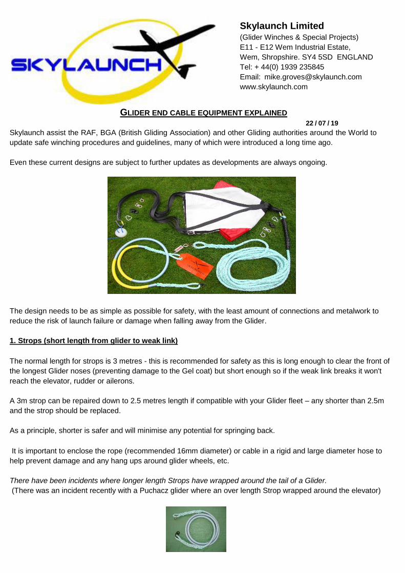
GLIDER END CABLE EQUIPMENT EXPLAINED
22 / 07 / 19
Skylaunch assist the RAF, BGA (British Gliding Association) and other Gliding authorities around the World to
update safe winching procedures and guidelines, many of which were introduced a long time ago.
Even these current designs are subject to further updates as developments are always ongoing.
The design needs to be as simple as possible for safety, with the least amount of connections and metalwork to
reduce the risk of launch failure or damage when falling away from the Glider.
1. Strops (short length from glider to weak link)
The normal length for strops is 3 metres - this is recommended for safety as this is long enough to clear the front of
the longest Glider noses (preventing damage to the Gel coat) but short enough so if the weak link breaks it won't
reach the elevator, rudder or ailerons.
A 3m strop can be repaired down to 2.5 metres length if compatible with your Glider fleet – any shorter than 2.5m
and the strop should be replaced.
As a principle, shorter is safer and will minimise any potential for springing back.
It is important to enclose the rope (recommended 16mm diameter) or cable in a rigid and large diameter hose to
help prevent damage and any hang ups around glider wheels, etc.
There have been incidents where longer length Strops have wrapped around the tail of a Glider.
(There was an incident recently with a Puchacz glider where an over length Strop wrapped around the elevator)
Skylaunch Limited (Glider Winches & Special Projects)