226
User’s Guide Global Array Manager® Client Software English
User’s Guide
Global Array Manager® Client Software
English

®
DB15-000278-03
Global Array Manager® Transition Tool Client Software
USER�SGUIDE
F e b r u a r y 2 0 0 6
Version 3.1

iiVersion 3.1 Copyright © 2001�2006 by LSI Logic Corporation. All rights reserved.
This document contains proprietary information of LSI Logic Corporation. The information contained herein is not to be used by or disclosed to third parties without the express written permission of an officer of LSI Logic Corporation.
Document DB15-000278-03, Version 3.1 (February 2006)This document describes version 7.0 of LSI Logic Corporation�s Global Array Management Client software. This document will remain the official reference source for all revisions/releases of this product until rescinded by an update.
LSI Logic Corporation reserves the right to make changes to any products herein at any time without notice. LSI Logic does not assume any responsibility or liability arising out of the application or use of any product described herein, except as expressly agreed to in writing by LSI Logic; nor does the purchase or use of a product from LSI Logic convey a license under any patent rights, copyrights, trademark rights, or any other of the intellectual property rights of LSI Logic or third parties.
Copyright © 2001�2006 by LSI Logic Corporation. All rights reserved.
TRADEMARK ACKNOWLEDGMENTLSI Logic, the LSI Logic logo design, Integrated Mirroring, MORE, Mylex, eXtremeRAID, MegaRAID, AcceleRAID, and Global Array Manager are trademarks or registered trademarks of LSI Logic Corporation. Microsoft and Windows are trademarks or registered trademarks of Microsoft Corporation. Linux is a registered trademark of Linus Torvalds. Pentium is a registered trademark of Intel Corporation. All other brand and product names may be trademarks of their respective companies.
KL
To receive product literature, visit us at http://www.lsilogic.com.
For a current list of our distributors, sales offices, and design resource centers, view our web page located at
http://www.lsilogic.com/contacts/index.html

Global Array Manager Transition Tool Client Software User�s Guide iiiVersion 3.1 Copyright © 2001�2006 by LSI Logic Corporation. All rights reserved.
Preface
This user�s guide explains how to install and use the client component of the Mylex® Global Array Manager® Transition Tool with LSI Logic MegaRAID® Ultra 320 controllers, MegaRAID SATA Software RAID, Ultra320 SCSI controllers, SAS controllers, and Mylex PCI Disk Array controllers.
For information on installing and running the server component of Global Array Manager Transition Tool, see the Global Array Manager Transition Tool Server User�s Guide, DB15-000279-03.
Audience
This document assumes that you are familiar with RAID controllers and related support devices.
The people who benefit from this book are
• network administrators who need to install and use Global Array Manager Transition Tool with LSI Logic controllers
• engineers and managers who are evaluating LSI Logic controllers for possible use in a system
Organization
This document has the following chapters and appendixes:
• Chapter 1, Introduction, introduces the Global Array Manager
Transition Tool (GAMTT) Client software.
• Chapter 2, Installation, explains how to install the GAMTT Client software.

iv PrefaceVersion 3.1 Copyright © 2001�2006 by LSI Logic Corporation. All rights reserved.
• Chapter 3, Startup, Overview, and Setup, describes how to start and navigate through the GAMTT Client.
• Chapter 4, Configuration, describes how to use the RAID Assist configuration wizard to create or change RAID storage configurations.
• Chapter 5, Monitoring Events, Devices, and Processes, explains how to use GAMTT client to monitor storage devices and RAID storage configurations.
• Chapter 6, Maintaining Storage Configurations, describes how to use GAMTT Client to maintain storage devices and RAID storage configurations.
• Chapter 7, Using GAMTT with Embedded MegaRAID Software, describes how to use GAMTT Client with MegaRAID SATA Software RAID.
• Appendix A, Event and Message Information, provides descriptions of GAMTT events and Spy messages.
Conventions
Throughout the manual, the following conventions are used to describe user interaction with the product:
Note: Notes contain supplementary information that can have an effect on system performance.
Caution: Cautions are notifications that an action has the potential to adversely affect equipment operation, system performance, or data integrity.
Convention Definition
bold Enter the bold text exactly as shown.
↵ Press the Enter key.
Enter Press the key labeled �Enter� (or �Delete�, etc.)
File->Run Select the Run option from the pull-down menu activated when the File menu option is selected.

Preface vVersion 3.1 Copyright © 2001�2006 by LSI Logic Corporation. All rights reserved.
WARNING: Warnings are notifications that an action will definitely result in equipment damage, data loss, or personal injury.
Revision History
Document Number Version/Date Remarks
DB15-000278-03 Version 3.1February, 2006
Added support for SAS controllers. Added new GAMTT events.
DB15-000278-02 Version 3.0August, 2004
Added support for MegaRAID Ultra320 PCI Express controllers.Added new information about MegaRAID SATA Software RAID.New error logging support for IME controllers.Added new event descriptions to Appendix A.Administrator privileges no longer restricted to �gamroot� user. Passwords now required for all GAMTT users.
DB15-000278-01 Version 2.0March, 2004
Added Chapter 7 to document - �GAMTT Support for Mega-RAID SATA Software RAID.�Added new event descriptions to Appendix A.Added information about IME (Integrated Mirroring� Enhanced) throughout the document.Revised Chapter 2, �Installation.� Added list of Spy messages to Appendix A.
DB15-000278-00 Version 1.0May, 2003
Original release of this document.

vi PrefaceVersion 3.1 Copyright © 2001�2006 by LSI Logic Corporation. All rights reserved.

Contents viiVersion 3.1 Copyright © 2001�2006 by LSI Logic Corporation. All rights reserved.
Contents
Chapter 1Introduction
1.1 Overview 1-11.1.1 Creating Storage Configurations 1-11.1.2 Monitoring Storage Configurations 1-21.1.3 Maintaining Storage Configurations 1-2
1.2 Hardware and Software Requirements 1-21.2.1 Hardware Requirements 1-21.2.2 Software Requirements 1-3
Chapter 2Installation
2.1 Installation Overview 2-12.2 Installing GAMTT Client Software 2-1
Chapter 3Startup, Overview, and Setup
3.1 Starting Global Array Manager Transition Tool (GAMTT) 3-13.2 Main GAMTT Client Windows 3-2
3.2.1 Global Array Manager Window 3-23.2.2 Controller View Window 3-5
3.3 Device Icons and Toolbar Icons 3-83.4 Menu Options 3-9
3.4.1 File Menu 3-93.4.2 View Menu 3-103.4.3 Administration Menu 3-113.4.4 Window Menu and Help Menu 3-12
3.5 Setting Up Server Groups and Servers 3-133.5.1 Adding a Server Group to the Server Group List 3-13

viii ContentsVersion 3.1 Copyright © 2001�2006 by LSI Logic Corporation. All rights reserved.
3.5.2 Adding Servers to a Server Group 3-133.6 Signing On to a Server 3-14
3.6.1 Security Access Levels 3-143.6.2 Sign On Procedure 3-15
3.7 Setting and Modifying User Preferences 3-163.7.1 Alert Preferences Tab 3-163.7.2 Alarm Setup Tab 3-173.7.3 Communication Tab 3-233.7.4 Event Editor Tab 3-24
Chapter 4Configuration
4.1 Introduction 4-24.2 Setting and Changing Controller Options 4-3
4.2.1 Controller Options Tab 4-34.2.2 Advanced Controller Options Tab 4-5
4.3 Modifying Physical Device Options 4-74.4 Running RAID Assist 4-8
4.4.1 Opening RAID Assist 4-94.4.2 Automatic Configuration 4-104.4.3 Assisted Configuration 4-124.4.4 Manual Configuration 4-16
4.5 Adding a Logical Drive on MegaRAID, SAS, and Mylex Controllers 4-22
4.6 Creating Hot Spares 4-234.7 Expanding Capacity 4-25
4.7.1 Expanding Capacity on Mylex Controllers 4-254.7.2 Expanding an Array on MegaRAID and SAS
Controllers 4-284.8 Deleting a Logical Drive 4-314.9 Migrating a RAID Level 4-324.10 Transporting a Disk Array (Mylex Controllers Only) 4-334.11 Clustering 4-354.12 Managing Channels 4-354.13 Spanning in GAMTT 4-374.14 Enable Spanning in GAMTT 4-394.15 Configuring a Spanned Disk Array 4-39
4.15.1 Creating a Spanned Disk Array 4-39

Contents ixVersion 3.1 Copyright © 2001�2006 by LSI Logic Corporation. All rights reserved.
4.16 Loading a Configuration from Disk 4-414.17 Saving a Configuration to Disk 4-414.18 Creating Configurations on Integrated RAID Controllers 4-42
Chapter 5Monitoring Events, Devices, and Processes
5.1 Monitoring Events 5-15.1.1 Opening the Log Information Viewer 5-25.1.2 Opening an Event Information Window 5-2
5.2 Monitoring Controllers 5-35.2.1 Displaying Controller Information 5-3
5.3 Monitoring Physical Devices and Logical Drives 5-55.3.1 Displaying Device Information 5-55.3.2 Viewing the IR Error Log (Integrated RAID
Configurations Only) 5-85.3.3 Viewing the Request Sense Data and NVRAM
Error Log 5-95.3.4 Displaying Logical Drive Information 5-13
5.4 Monitoring Enclosures 5-155.4.1 Information Page 5-155.4.2 Details Page 5-165.4.3 Enclosures Devices 5-19
5.5 Monitoring the Status of Processes 5-205.5.1 Background and Foreground Initialization Status 5-205.5.2 Rebuild Status 5-215.5.3 Consistency Check Status 5-225.5.4 Expand Capacity Status 5-235.5.5 Patrol Status 5-23
5.6 Monitoring and Maintaining Battery Backup Units 5-245.6.1 Intelligent BBU for Mylex PCI RAID Controllers 5-245.6.2 Intelligent BBU for MegaRAID Ultra320-2E and
SAS Controllers 5-26
Chapter 6Maintaining Storage Configurations
6.1 Initializing a Logical Drive 6-16.2 Running a Logical Drive Consistency Check 6-2

x ContentsVersion 3.1 Copyright © 2001�2006 by LSI Logic Corporation. All rights reserved.
6.3 Running a Device Rebuild 6-36.4 Using the Flash Utility 6-56.5 Defragmenting an Array (Mylex Controllers Only) 6-86.6 Clearing a Configuration 6-9
Chapter 7Using GAMTT with Embedded MegaRAID Software
7.1 Main GAMTT Client Windows 7-27.1.1 Global Array Manager Window 7-27.1.2 Controller View Window 7-5
7.2 Device Icons, Toolbar Icons, and Menus 7-67.2.1 GAMTT File Menu 7-77.2.2 GAMTT View Menu 7-77.2.3 GAMTT Administration Menu 7-87.2.4 GAMTT Window Menu and Help Menu 7-9
7.3 Configuration 7-97.3.1 Setting and Changing Controller Options 7-10
7.4 Running RAID Assist 7-117.4.1 Opening RAID Assist 7-127.4.2 Automatic Configuration 7-137.4.3 Assisted Configuration 7-157.4.4 Manual Configuration 7-18
7.5 Adding a Logical Drive 7-217.6 Deleting a Logical Drive 7-237.7 Creating Hot Spares 7-247.8 Loading a Configuration from Disk 7-247.9 Saving a Configuration to Disk 7-257.10 Clearing a Configuration 7-257.11 Monitoring Activities 7-25
7.11.1 Monitoring Events 7-267.11.2 Opening the Log Information Viewer 7-267.11.3 Opening an Event Information Window 7-267.11.4 Monitoring Physical Devices and Logical Drives 7-277.11.5 Monitoring Foreground Initialization Status 7-307.11.6 Monitoring Rebuild Status 7-307.11.7 Monitoring Consistency Check Status 7-31
7.12 Maintenance Processes 7-32
Contents xiVersion 3.1 Copyright © 2001�2006 by LSI Logic Corporation. All rights reserved.
7.12.1 Running a Logical Drive Initialization 7-327.12.2 Running a Logical Drive Consistency Check 7-337.12.3 Running a Device Rebuild 7-34
Appendix AEvent and Message Information
A.1 Overview A-1A.2 GAMTT Events A-2A.3 Spy Messages A-34
Glossary
Customer Feedback

xii ContentsVersion 3.1 Copyright © 2001�2006 by LSI Logic Corporation. All rights reserved.

Contents xvVersion 3.1 Copyright © 2001�2006 by LSI Logic Corporation. All rights reserved.
Figures2.1 Select Components to Install 2-23.1 GAMTT Client Opening Message 3-23.2 Opening Global Array Manager Window 3-33.3 Controller View Window � �Non-Fibre� RAID Controller 3-53.4 Controller View Window � eXtremeRAID 3000 Controller 3-73.5 Controller View Window �SAS Controllers 3-73.6 Sign On Dialog Box 3-153.7 Settings Dialog Box � Alert Preferences 3-163.8 Settings Dialog Box � Alarm Setup 3-173.9 Pager Dialog Box 3-183.10 Fax Dialog Box 3-203.11 E-mail Dialog Box 3-213.12 Launch Application Dialog Box 3-223.13 Settings Dialog Box � Communication 3-233.14 Settings Dialog Box � Event Editor 3-244.1 Configuration Lock Notification 4-24.2 Controller Options Dialog Box 4-34.3 Advanced Controller Options Dialog Box 4-64.4 Physical Device Options Dialog Box 4-74.5 RAID Assist �Welcome� Dialog Box 4-94.6 Select �New Configuration� 4-104.7 Automatic Configuration->New Configuration->Finish 4-114.8 Select �New Configuration� 4-124.9 Background Initialization is Supported 4-144.10 Assisted Configuration ->New Configuration ->Finish 4-154.11 Select �New Configuration� 4-174.12 Manual Configuration � Disk Arrays 4-174.13 Manual Configuration � Logical Drives 4-194.14 Sample Manual Configuration Just Before �Apply� 4-214.15 Logical Drives Tab 4-224.16 Add Logical Drive(s) 4-234.17 Creating a Global Hot Spare 4-244.18 Creating a Dedicated Hot Spare 4-254.19 Adding Physical Drives to an Array 4-274.20 Logical Drives Tab 4-274.21 Select a Logical Drive 4-29

xvi ContentsVersion 3.1 Copyright © 2001�2006 by LSI Logic Corporation. All rights reserved.
4.22 Adding Physical Drives to an Array 4-294.23 Logical Drives Tab 4-304.24 Deleting a Logical Drive 4-314.25 Logical Drive Information Window � Transport Button 4-344.26 Disk Array Transport Information Window 4-344.27 Disk Array Tab � Four Channels Displayed 4-364.28 Controller View � Four Channels Displayed 4-364.29 Creating a Spanned Array 4-404.30 RAID Assist Welcome Dialog Box 4-434.31 RAID Assist List of Available Drives 4-444.32 Summary of Disk Array Configuration 4-455.1 Event Information Window 5-25.2 Controller Information 5-45.3 Host Device Information � Mylex Controller 5-55.4 Disk Device Information 5-65.5 PFA Information Window 5-75.6 Integrated Raid (IR) Error Log 5-95.7 Request Sense Data 5-105.8 NVRAM Error Log 5-115.9 Logical Drive Information 5-135.10 Enclosure Information Page 5-155.11 SES Enclosure Information � Details Page 5-165.12 Enclosure Device Information 5-195.13 Foreground Initialization Status Box Shown 5-205.14 Rebuild Status Box 5-215.15 Consistency Check Status Box 5-225.16 Expand Capacity Status Box 5-235.17 Patrol Read Status Dialog Box 5-235.18 Intelligent BBU Dialog Box: Mylex PCI RAID Controllers 5-245.19 Intelligent BBU Dialog Box: SAS and MegaRAID
Ultra320-E Controllers 5-266.1 Initialize Logical Drives Dialog Box 6-26.2 Rebuild Button Available for This Disk Device 6-46.3 Flash Utility Dialog Box 6-56.4 Additional Flash File Information 6-76.5 Manual Configuration/Defragment Array 6-86.6 Mylex Only - Clear Configuration Dialog Box 6-97.1 Opening Global Array Manager Window 7-3

Contents xviiVersion 3.1 Copyright © 2001�2006 by LSI Logic Corporation. All rights reserved.
7.2 Controller View Window � �SATA� RAID Adapter 7-57.3 Configuration Lock Notification 7-107.4 Controller Options Dialog Box 7-107.5 RAID Assist �Welcome� Dialog Box 7-127.6 Automatic Configuration Screen 7-137.7 Automatic Configuration->New Configuration->Finish 7-147.8 Select �New Configuration� 7-157.9 Assisted Configuration ->New Configuration ->Finish 7-177.10 Manual Configuration � Disk Arrays 7-187.11 Manual Configuration � Logical Drives 7-197.12 Sample Manual Configuration Just Before �Apply� 7-217.13 Logical Drives Tab 7-227.14 Add Logical Drive(s) 7-227.15 Deleting a Logical Drive 7-237.16 Event Information Window 7-277.17 Device Information 7-287.18 Error Log Information Screen 7-297.19 Logical Drive Information 7-297.20 Foreground Initialization Status Box 7-307.21 Rebuild Status Box 7-317.22 Consistency Check Status Box 7-317.23 Select �Initialize� 7-327.24 Select �Consistency Check� 7-337.25 Rebuild Button Available for This Disk Device 7-35

xviii ContentsVersion 3.1 Copyright © 2001�2006 by LSI Logic Corporation. All rights reserved.

Contents xixVersion 3.1 Copyright © 2001�2006 by LSI Logic Corporation. All rights reserved.
Tables4.1 Mylex Controller RAID Level Migration 4-324.2 MegaRAID and SAS Controller RAID Level Migration 4-334.3 Configuring a Spanned Array with Mylex Controllers 4-384.4 Configuring a Spanned Array with MegaRAID or SAS
Controllers 4-38A.1 Severity Level Priorities and Descriptions A-1A.2 GAMTT Events for PCI Controllers A-2A.3 Spy Log Messages A-34A.4 Linux Spy Error Messages Posted to Console A-37

xx ContentsVersion 3.1 Copyright © 2001�2006 by LSI Logic Corporation. All rights reserved.
Global Array Manager Transition Tool Client Software User�s Guide 1-1Version 3.1 Copyright © 2001�2006 by LSI Logic Corporation. All rights reserved.
Chapter 1Introduction
1.1 Overview
You use Global Array Manager Transition Tool (GAMTT) Client software to create, monitor, and maintain storage configurations on a wide variety of LSI Logic and Mylex RAID controllers. (Embedded software RAID products are also supported.) If you also install the GAMTT server component, you can monitor storage configurations on multiple networked servers.
This manual explains how to use all the features of the GAMTT Client software, which supports the following RAID storage controllers and software RAID products:
• MegaRAID Ultra320-0, -1, -2, -0X, -2X, -4X, -2E RAID controllers
• MegaRAID SAS 8408E, 8480E, 8344ELP, 8308ELP, 8300XLP, 8808E, 8208XLP, 8208ELP, and 8300XLP controllers
• MegaRAID SAS 3442X Integrated RAID controller
• Ultra320 SCSI controller, including support for Integrated Mirroring� Enhanced (IME) arrays (see Section 4.18, �Creating Configurations on Integrated RAID Controllers�)
• Embedded MegaRAID for SATA
• MegaRAID SATA Software RAID (see Chapter 7, �Using GAMTT with Embedded MegaRAID Software�)
• eXtremeRAID® 2000/3000 controllers
• AcceleRAID® 160/170/170LP/352 controllers
1.1.1 Creating Storage Configurations
Configuration functions are easily performed with RAID Assist, an intuitive, wizard-like utility in the GAMTT Client software that simplifies
1-2 IntroductionVersion 3.1 Copyright © 2001�2006 by LSI Logic Corporation. All rights reserved.
the process of setting up or reconfiguring a disk array. Just answer a few brief questions, and RAID Assist automatically does the rest. Use manual configuration for more control over drive group setup or individual configuration parameters.
1.1.2 Monitoring Storage Configurations
The GAMTT Server component collects and disseminates information on disk array status. The GAMTT Client component organizes and displays this information in an intuitive graphical display. Errors and events are recorded in a log file and in the Log Information Viewer window. If a problem requires immediate attention, operators can be alerted via popup windows, pagers, fax, or E-mail.
1.1.3 Maintaining Storage Configurations
The GAMTT Client manages or performs maintenance on individual disk arrays and drives (with the appropriate authentication), by means of the graphical user interface. This includes removing physical devices from operation in a functioning disk array (also known as �killing� or off-lining a drive), rebuilding drives, and initiating a consistency check on arrays that support redundancy. The GAMTT Server executes the management instructions specified by the GAMTT Client software.
1.2 Hardware and Software Requirements
Since GAMTT is a client/server application, the GAMTT Server software must be installed in one or more file servers in order for the GAMTT Client software to operate. Hardware and software requirements for the GAMTT Client software are as follows.
1.2.1 Hardware Requirements• PC-compatible computer with an 80486 or higher class processor
and at least 4 Mbytes of system memory (Pentium processor and 16 Mbytes of system memory are recommended)
• Network interface card connected to a functioning network
• Hard disk drive with at least 8 Mbytes available free space (16 Mbytes recommended)

Hardware and Software Requirements 1-3Version 3.1 Copyright © 2001�2006 by LSI Logic Corporation. All rights reserved.
• Mouse or other pointing device
• A minimum display screen setting of 800 x 600 is recommended. A screen setting of 1024 x 768 is recommended for optimum GAMTT Client viewing.
• (optional) Modem or Fax/Modem (Hayes-compatible)
1.2.2 Software Requirements• Microsoft Windows 2000/2003/XP 32-bit, XP 32-bit, or Windows
95/98/Me installed on a local hard disk
• For proper client component connectivity, installed and functioning GAMTT Server software component on the server, under any supported operating system
• TCP/IP stack installed
• (optional) MAPI- or SMTP-compliant messaging such as Microsoft Outlook (Required for Windows)
• (optional) Microsoft Exchange, and Microsoft At Work (Windows 95) for fax notification of events
Refer to your server documentation and to the Windows documentation for more information on hardware and operating system requirements.

1-4 IntroductionVersion 3.1 Copyright © 2001�2006 by LSI Logic Corporation. All rights reserved.

Global Array Manager Transition Tool Client Software User�s Guide 2-1Version 3.1 Copyright © 2001�2006 by LSI Logic Corporation. All rights reserved.
Chapter 2Installation
2.1 Installation Overview
The GAMTT Client software is supported on the following operating systems:
• Microsoft Windows 2000/2003/XP 32-bit
• Windows 95/98/Me
This chapter assumes that the network administrator for this site will install this software.
If you are installing GAMTT Client software, you may also choose to install GAMTT Server software and its subcomponents at the same time on the same system. When installing GAMTT Server software, dialog boxes for the server component open and require a computer restart before launching the GAMTT Client software. Refer to the Global Array Manager Transition Tool Server User�s Guide for installation instructions.
2.2 Installing GAMTT Client Software
Follow these steps to install GAMTT Client software with Microsoft Windows:
Note: If you intend to install GAMTT Server with GAMTT Client, make sure TCP/IP is installed and functioning properly.
1. Go to the LSI Logic website (http://www.lsilogic.com) and select Downloads.
2. On the Downloads page, select information about the RAID hardware product under Steps 1, 2, and 3. For example:

2-2 InstallationVersion 3.1 Copyright © 2001�2006 by LSI Logic Corporation. All rights reserved.
Step 1: SCSI RAID AdaptersStep 2: Ultra320 SCSI RAIDStep 3: MegaRAID SCSI 320-1
3. Select All file types under Step 4, and click GO.
4. Scroll to the �Miscellaneous� category on the page of available downloads, and click Windows GAM.
5. Read the download agreement, and click I accept.
6. When the File Download screen appears, click Save to save the zip file to your computer.
7. Unzip the file after it has been downloaded.
8. Go to the unzipped GAM_install folder and double-click Setup.exe.
After a few moments, the Welcome dialog box appears.
9. Click Next to proceed with the installation.
10. When the LSI Logic Software License Agreement screen appears, click Yes to accept the terms of the agreement and continue.
The Select Components dialog box is displayed, as shown in Figure 2.1.
Figure 2.1 Select Components to Install
11. Click the box (if necessary) to select Global Array Manager Client.

Installing GAMTT Client Software 2-3Version 3.1 Copyright © 2001�2006 by LSI Logic Corporation. All rights reserved.
Note: You can also choose to install Global Array Manager Server software at this time. See the instructions in the Global Array Manager Transition Tool Server User�s Guide.
12. Click Next and follow the on-screen prompts.

2-4 InstallationVersion 3.1 Copyright © 2001�2006 by LSI Logic Corporation. All rights reserved.

Global Array Manager Transition Tool Client Software User�s Guide 3-1Version 3.1 Copyright © 2001�2006 by LSI Logic Corporation. All rights reserved.
Chapter 3Startup, Overview, and Setup
This chapter explains how to start Global Array Management Client. It provides a general description of the main Global Array Management Client windows. It also lists the toolbar icons and menu options and explains other tasks involved in initial setup of the program�s access and monitoring functions. This chapter has the following sections:
• Section 3.1, �Starting Global Array Manager Transition Tool (GAMTT)�
• Section 3.2, �Main GAMTT Client Windows�
• Section 3.3, �Device Icons and Toolbar Icons�
• Section 3.4, �Menu Options�
• Section 3.5, �Setting Up Server Groups and Servers�
• Section 3.6, �Signing On to a Server�
• Section 3.7, �Setting and Modifying User Preferences�
3.1 Starting Global Array Manager Transition Tool (GAMTT)
You must install and start GAMTT Server software before you can run the Global Array Manager Client. Refer to the Global Array Manager Transition Tool Server User�s Guide for instructions on installing and starting GAMTT Server software.
To start GAMTT Client software, select Start->Programs->Mylex Global Array Manager Client. At startup, the GAMTT Client displays the following message (Figure 3.1).

3-2 Startup, Overview, and SetupVersion 3.1 Copyright © 2001�2006 by LSI Logic Corporation. All rights reserved.
Figure 3.1 GAMTT Client Opening Message
This message notifies you that the event definition has been changed from the default after clicking OK from the Settings option. If you do not want this dialog box to open each time you start the GAMTT Client, select �Don�t display this dialog again.� Click OK to close the dialog box.
If at least one server group and file server are defined, the GAMTT Client opening screen appears (Figure 3.2). If not, the Define Server Groups dialog box opens (see Section 3.5, �Setting Up Server Groups and Servers,� page 3-13).
Note: LSI Logic recommends that you leave the GAMTT Client running as long as there are servers you want to monitor. If you exit, you cannot receive events from GAMTT Server, and you are will not be informed of errors or status unless you restart GAMTT Client and reconnect to the server(s).
3.2 Main GAMTT Client Windows
This section describes the main GAMTT window that appears when you start the program and the Controller View window, where you can view controller and device information.
3.2.1 Global Array Manager Window
If at least one server group is defined, the Global Array Manager window, shown in Figure 3.2 appears when you start GAMTT Client software. Within the Global Array Manager window are the Global Status View window and the Log Information Viewer.

Main GAMTT Client Windows 3-3Version 3.1 Copyright © 2001�2006 by LSI Logic Corporation. All rights reserved.
Figure 3.2 Opening Global Array Manager Window
The components of the Global Array Manager window are described below.
1. Menu bar: The menu options are described later in this chapter.
2. Toolbar: The toolbar icons are described in Section 3.3, �Device Icons and Toolbar Icons,� page 3-8.
3. Server group selection box: This drop-down menu lists each server group that is in contact with the current client workstation. Each group may consist of multiple servers. You may select a specific server group to view, or select �All Servers� if you want to view all the servers that are accessible from this workstation.
4. Controller selection box: This drop-down menu lists the controller ID (C-0, C-1, etc.) and controller type (eXtremeRAID 2000, etc.) of each controller connected to the currently-selected server.
3.2.1.1 Global Status View Window
The components of the Global Status View window (Figure 3.2) are described below:
#1 #2 #3 #4
#5 #6
#7
3-4 Startup, Overview, and SetupVersion 3.1 Copyright © 2001�2006 by LSI Logic Corporation. All rights reserved.
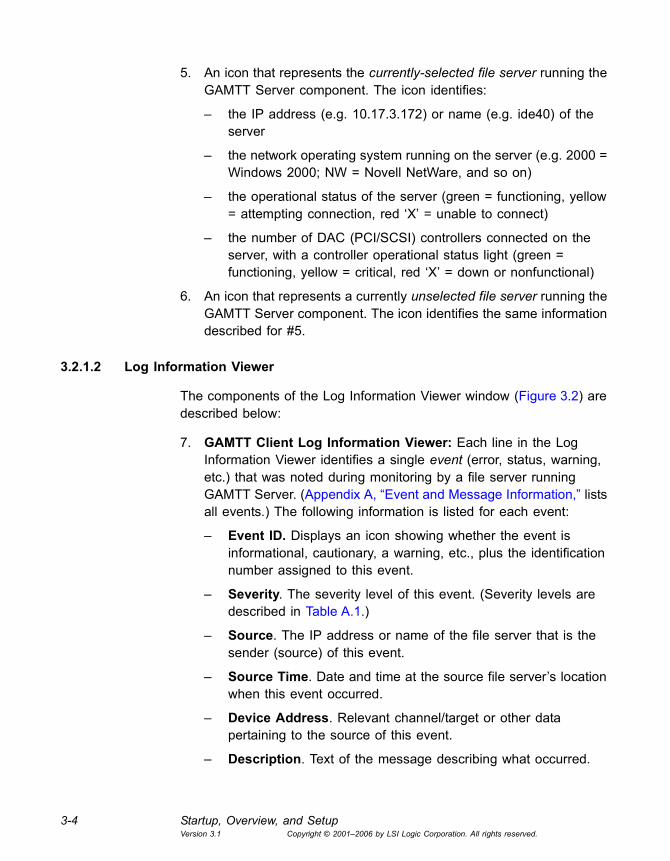
5. An icon that represents the currently-selected file server running the GAMTT Server component. The icon identifies:
� the IP address (e.g. 10.17.3.172) or name (e.g. ide40) of the server
� the network operating system running on the server (e.g. 2000 = Windows 2000; NW = Novell NetWare, and so on)
� the operational status of the server (green = functioning, yellow = attempting connection, red �X� = unable to connect)
� the number of DAC (PCI/SCSI) controllers connected on the server, with a controller operational status light (green = functioning, yellow = critical, red �X� = down or nonfunctional)
6. An icon that represents a currently unselected file server running the GAMTT Server component. The icon identifies the same information described for #5.
3.2.1.2 Log Information Viewer
The components of the Log Information Viewer window (Figure 3.2) are described below:
7. GAMTT Client Log Information Viewer: Each line in the Log Information Viewer identifies a single event (error, status, warning, etc.) that was noted during monitoring by a file server running GAMTT Server. (Appendix A, �Event and Message Information,� lists all events.) The following information is listed for each event:
� Event ID. Displays an icon showing whether the event is informational, cautionary, a warning, etc., plus the identification number assigned to this event.
� Severity. The severity level of this event. (Severity levels are described in Table A.1.)
� Source. The IP address or name of the file server that is the sender (source) of this event.
� Source Time. Date and time at the source file server�s location when this event occurred.
� Device Address. Relevant channel/target or other data pertaining to the source of this event.
� Description. Text of the message describing what occurred.

Main GAMTT Client Windows 3-5Version 3.1 Copyright © 2001�2006 by LSI Logic Corporation. All rights reserved.
� Sequence (Seq). Number representing where this event fell in a stream of events from the same source.
� Local Time. Date and time at the local client workstation�s location when this event arrived.
3.2.2 Controller View Window
To open the Controller View window, double-click any server icon in the Global Status View, or select View -> Controller View...
Note: If you want the Controller View window to show real-time information, and if you do not have a real IP address on the GAMTT server, you must set the GAMTT Server event notification destination address with the loop back IP address (127.0.0.1). See the Global Array Manager Transition Tool Server User�s Guide for instructions on how to update the server event file (gamscm.ini).
Figure 3.3 Controller View Window � �Non-Fibre� RAID Controller
#1 #2#3
#4 #5

3-6 Startup, Overview, and SetupVersion 3.1 Copyright © 2001�2006 by LSI Logic Corporation. All rights reserved.
The Controller View window (Figure 3.3), displays the following information about the controller currently selected in the controller selection box:
1. The number of channels on this controller, with each channel depicted as a tower.
2. The physical devices present on each channel, specifying the target ID, capacity of the device, device type, and device status. See Section 5.3, �Monitoring Physical Devices and Logical Drives,� page 5-5, for more information.
3. The logical drives configured on the controller, specifying the logical drive number, capacity, RAID level, and status.
4. The enclosure device present on each channel, specifying the device inquiry data (vendor, bus width, etc...), and the device state.
5. The host device present on each channel, specifying the device inquiry data (vendor, bus width, etc...), and the device state.
3.2.2.1 eXtremeRAID 3000 Controller
The Controller View window for the eXtremeRAID 3000 controller (Figure 3.4), displays the same information as described in the previous section. However, it is organized graphically to allow many more targets to be shown in each of the fibre channels, and the Controller View is scrollable.
The number of targets per column can be set in the gam2cl.ini file.
Channel 0 represents the internal SCSI channel.
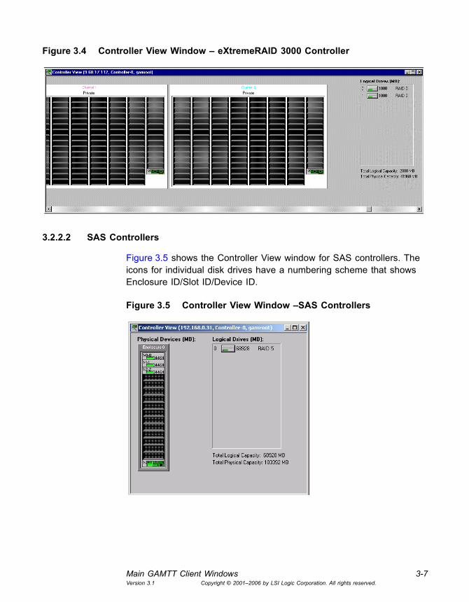
Main GAMTT Client Windows 3-7Version 3.1 Copyright © 2001�2006 by LSI Logic Corporation. All rights reserved.
Figure 3.4 Controller View Window � eXtremeRAID 3000 Controller
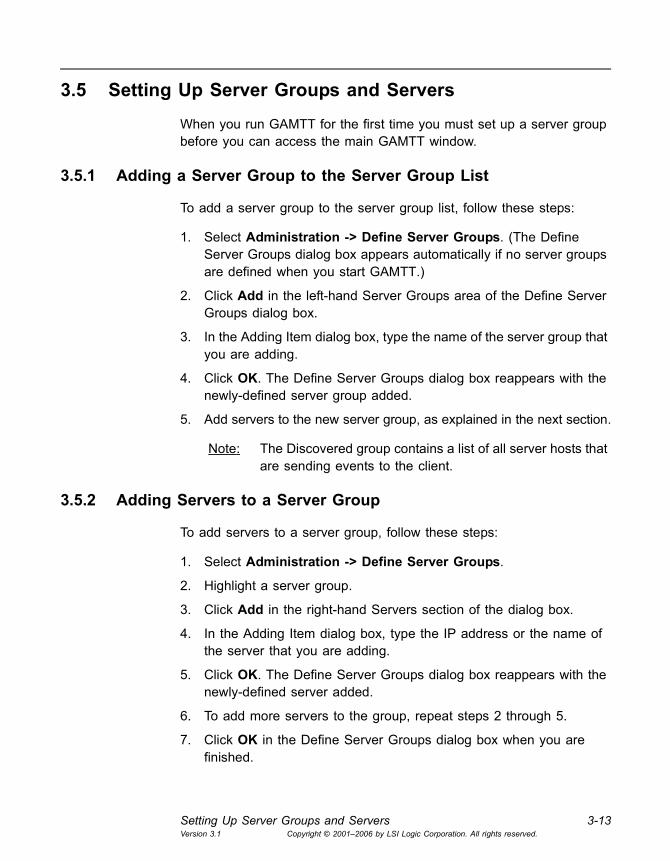
3.2.2.2 SAS Controllers
Figure 3.5 shows the Controller View window for SAS controllers. The icons for individual disk drives have a numbering scheme that shows Enclosure ID/Slot ID/Device ID.
Figure 3.5 Controller View Window �SAS Controllers

3-8 Startup, Overview, and SetupVersion 3.1 Copyright © 2001�2006 by LSI Logic Corporation. All rights reserved.
3.3 Device Icons and Toolbar Icons
The following icons display the status of logical and physical devices in the Controller View window:
The following buttons appear on the GAMTT Client toolbar.
Icon Description
Drive failed
Drive is temporarily off-line
Drive is online and functional
Drive is being rebuilt
Drive is unconfigured
Global spare physical device (dedicated spare device is the same, except the shade of the plus sign changes)
Logical drive is in critical state. Data will be lost if another physical drive fails.
Logical drive consistency check state
Logical drive is online and functional
Logical drive is offline
Icon Description
Disk Configuration Wizard: Brings up the RAID Assist dialog box for RAID controller configuration.
Scan Devices: Scans for recently added devices that are not yet identified within GAMTT.
Display Controller Information: Displays key information about the currently-selected RAID Controller or HBA.
Error Table: Displays a table of �request sense� data.

Menu Options 3-9Version 3.1 Copyright © 2001�2006 by LSI Logic Corporation. All rights reserved.
3.4 Menu Options
This section describes the Global Array Manager menu options.
Note: Some supported controllers do not support all of these menu options.
3.4.1 File Menu
The File menu contains the following options:
• Open Configuration (Ctrl+O): Loads a configuration from disk and saves it to the controller. (See Section 4.16, �Loading a Configuration from Disk,� page 4-41.)
• Save Configuration (Ctrl+S): Saves a configuration file to a new filename, disk, and/or directory.
• Clear Configuration: Removes logical drive information from the selected controller. This command works differently for controllers that support Integrated Mirroring (IM) and Integrated Mirroring Enhanced (IME) configurations. For more information, see Section 4.8, �Deleting a Logical Drive.�
WARNING: When you use the Clear Configuration option, all existing configuration information and data on all drives connected to the controller is deleted. Be sure to back up all data that you want to keep before you use this command!
• Exit: Exits the GAMTT Client.
Sign-On: Enables configuration and administration functions to Administrators and monitoring functions to �Users.�
Settings for Events: Opens a dialog box for specifying Alert/Alarm, Communication, and Event Editor settings.
Help Contents: Displays the on-line help contents page.
Icon Description

3-10 Startup, Overview, and SetupVersion 3.1 Copyright © 2001�2006 by LSI Logic Corporation. All rights reserved.
3.4.2 View Menu
The View menu contains the following options:
• Global Status View: Toggles the Global Status View window, which opens by default when you start GAMTT Client.
• Controller View: Toggles the Controller View window, which shows channel/ID/target information and physical device/logical drive configurations for the controller selected in the controller selection box.
• Log Information Viewer: Toggles the Log Information Viewer, which shows a log of recent system error and status event messages. The Log Information Viewer opens by default when you start GAMTT Client.
• Foreground Initialization Status: Displays the progress (percent complete) of an ongoing full foreground initialization of one or more drives.
• Background Initialization Status: Displays the progress (percent complete) of a currently running background initialization of one or more drives.
• Rebuild Status: Displays the progress (percent complete) of a currently running device rebuild.
• Consistency Check Status: Displays the progress (percent complete) of a currently running logical drive consistency check.
Note: For SAS controllers, this option is called Make Data Consistent Status.
• Expand Capacity Status: Displays the progress (percent complete) of a currently running restriping process across the target RAID group.
• Patrol Read Status: Enables GAMTT Client to poll every 1 minute to get new status data from the controller.
• Error Table: Displays a table of bad block and �request sense� data for all storage devices on the selected controller.
• Cluster Map (Mylex Controllers Only): Displays a graphical back end cable connection for the controller selected from the cluster controller list.

Menu Options 3-11Version 3.1 Copyright © 2001�2006 by LSI Logic Corporation. All rights reserved.
3.4.3 Administration Menu
The Administration menu contains the following options:
• Sign On: Enables Administrators to access GAMTT configuration and administration functions by using an appropriate username and password. Enables Users to monitor system status.
• Define Server Groups: Sets up server groups and individual server names or IP addresses within each group.
• Select Current Server Group (Ctrl+G): Displays the current contents of the server selection box located in the Global Array Manager window. Functions in the same way as directly selecting the server selection box.
• Select Current Controller (Ctrl+C): Displays the current contents of the controller selection box located in the Global Array Manager window. Functions in the same way as directly selecting the controller selection box.
• RAID Assist: Starts the built-in RAID Assist utility. Facilitates configuration tasks using either one-step �automatic� configuration, a configuration �wizard� assistant, or a manual (advanced level) configuration option allowing more control over configuration parameters.
• Initialize Logical Drives: Enables you to initialize logical drives at a later time of your choice, instead of immediately after a new configuration.
WARNING: Do not initialize a logical drive that you are currently using for data storage, or the data stored on the drive will be deleted.
• Controller Information: Displays information about the currently-selected controller.
• Enclosure Information: Displays information about components in the external disk enclosure.
• Controller Options: Enables you to set various parameters, such as cache line size and background initialization rate, for the selected disk array controller.
• Physical Device Options: Displays a list of all physical devices connected to the currently selected controller and allows the user to

3-12 Startup, Overview, and SetupVersion 3.1 Copyright © 2001�2006 by LSI Logic Corporation. All rights reserved.
change transfer speed, transfer width, and/or tag value for individual devices.
• Intelligent BBU: (Enabled only if the selected controller has an Intelligent Battery Backup Unit) Displays a dialog box from which you can do the following:
� Monitor the power remaining in the Intelligent BBU
� Set the low power threshold and perform other actions
For more information on Intelligent BBU support, see Section 5.6, �Monitoring and Maintaining Battery Backup Units,� page 5-24.
• Scan Devices: Scans for recently added devices that are not currently identified within GAMTT Client.
• Advanced Functions: Opens a submenu from which you can select the Flash Utility. You use the Flash Utility to upgrade the controller firmware, BIOS, boot block, or BIOS configuration utility as new maintenance releases become available.
• Settings: Opens a dialog box in which you can specify Alert/Alarm, Communication, and Event Editor settings. These settings include type of alarm (pager, fax, E-mail, etc.), modem baud rate, COM port, stop bits, data bits, parity, and event severity level.
• Alarm Sound (MegaRAID and SAS controllers only): Opens a submenu where you can enable, disable, or silence the audible alarm. (Refer to your controller hardware guide for a description of the audible warnings and their meaning.)
• Consistency Check with Restoration (MegaRAID controllers only): Opens a submenu where you can enable or disable the consistency check with restoration. (Disabled is the default setting.) When a consistency check is performed and inconsistent data is found, that data is restored. When the restoration feature is disabled, a bad block table is prepared for inconsistent data.
3.4.4 Window Menu and Help Menu
These are the standard Window and Help menus used in all Microsoft Windows applications.
Setting Up Server Groups and Servers 3-13Version 3.1 Copyright © 2001�2006 by LSI Logic Corporation. All rights reserved.
3.5 Setting Up Server Groups and Servers
When you run GAMTT for the first time you must set up a server group before you can access the main GAMTT window.
3.5.1 Adding a Server Group to the Server Group List
To add a server group to the server group list, follow these steps:
1. Select Administration -> Define Server Groups. (The Define Server Groups dialog box appears automatically if no server groups are defined when you start GAMTT.)
2. Click Add in the left-hand Server Groups area of the Define Server Groups dialog box.
3. In the Adding Item dialog box, type the name of the server group that you are adding.
4. Click OK. The Define Server Groups dialog box reappears with the newly-defined server group added.
5. Add servers to the new server group, as explained in the next section.
Note: The Discovered group contains a list of all server hosts that are sending events to the client.
3.5.2 Adding Servers to a Server Group
To add servers to a server group, follow these steps:
1. Select Administration -> Define Server Groups.
2. Highlight a server group.
3. Click Add in the right-hand Servers section of the dialog box.
4. In the Adding Item dialog box, type the IP address or the name of the server that you are adding.
5. Click OK. The Define Server Groups dialog box reappears with the newly-defined server added.
6. To add more servers to the group, repeat steps 2 through 5.
7. Click OK in the Define Server Groups dialog box when you are finished.
3-14 Startup, Overview, and SetupVersion 3.1 Copyright © 2001�2006 by LSI Logic Corporation. All rights reserved.
To delete a server, select the server name and click Remove.
Note: To see all servers in the Global Status view, select All Servers from the drop-down menu at the top of the window.
3.6 Signing On to a Server
This section describes the different server access levels and the methods of signing onto the GAMTT Client. GAMTT does not allow blank passwords. A password must be defined for every GAMTT user.
3.6.1 Security Access Levels
The GAM user access level determines what you can view and what actions you can perform in GAMTT Client. GAMTT takes advantage of the security features built into your operating system to offer two user access levels:
• Guest: Guest access level requires signing on to a server host with a username and password that are not defined with administrative privileges. Guest access level allows you to monitor the Log Information Viewer and the Global Status View window. It does not allow you to view or make changes to any controller parameters or array configurations.
• Administrator: Administrator access level requires signing on to a server host with the gamroot username or with another username that is defined with administrative privileges. The username must have a password.
Administrator access level enables you to view all GAM information, including controller information. It also enables you to perform GAM tasks such as configuring arrays, rebuilding drives, and so on.
Note: The GAMTT Administrator access level is not the same as the Windows log-on name �Administrator.� You must use the administrator username and the password associated with it in order to access the GAMTT server host as an Administrator. GAMTT users with administrative access level should be granted Windows Administrator privileges or Linux root privileges.

Signing On to a Server 3-15Version 3.1 Copyright © 2001�2006 by LSI Logic Corporation. All rights reserved.
3.6.2 Sign On Procedure
You must sign on to a server host before you can view controller information or change controller configuration. To sign on to a server, follow these steps:
1. Click , double-click a server icon in Global Status View, or select Sign-on from the Administration menu.
The Sign On dialog box opens if you have not signed on during this session or if you did not check the Remember password box in the Sign On dialog box when you signed on before (see Figure 3.6).
If you signed on before and did check the Remember password box, the previously entered username and password are automatically used for this new sign on.
Figure 3.6 Sign On Dialog Box
2. Enter your user name.
3. Enter the appropriate password.
4. Check the box labeled Remember password for this session if you want GAMTT to skip the Sign On messages each time you select a server during this session which uses the same password. Uncheck the box if you want to retain the option of signing on to each server you wish to access individually.
5. Click Sign-on.

3-16 Startup, Overview, and SetupVersion 3.1 Copyright © 2001�2006 by LSI Logic Corporation. All rights reserved.
3.7 Setting and Modifying User Preferences
To set or modify user preferences, select Administration->Settings on
the menu bar, or click the Preferences icon . The Settings dialog box has several tabs, which are described in the following sections.
3.7.1 Alert Preferences Tab
Figure 3.7 Settings Dialog Box � Alert Preferences
The Alert Preferences tab (Figure 3.7) lets you control the event log and the way in which GAMTT sends alerts for various kinds of events.
3.7.1.1 Event Log
In the Event Log area of the Alert Preferences tab, you can enable or disable the event logging feature. You can also choose to append new events to your current log file or to replace the current log file with a new one.

Setting and Modifying User Preferences 3-17Version 3.1 Copyright © 2001�2006 by LSI Logic Corporation. All rights reserved.
3.7.1.2 Enable Global Alerts for Severity Level(s)
The check boxes in the lower section of the Alert Preferences tab represent the categories of events, (0 � Critical; 1 � Serious; 2 � Error; 3 � Warning; 4 � Informational). The event categories can be edited in the Event Editor tab. For a complete list of GAMTT events, see Appendix A, �Event and Message Information.�
For each type of alarm (E-mail, Pager, and so on) check the box(es) corresponding to the event severity level(s) for which you want to enable this type of alarm globally. For example, in Figure 3.7 all Level 0 events trigger a local alarm sound and send an E-mail, page, and fax to the individuals identified in Alarm Setup.
After you change the settings, click OK to save the changes and exit, or click Cancel to exit without saving, or click another Settings tab to continue working.
3.7.2 Alarm Setup Tab
Figure 3.8 Settings Dialog Box � Alarm Setup
The top half of the Alarm Setup dialog box (Figure 3.8) lists the types of alarms that can be used (Pager, Fax, E-mail, Launch Application). The lower half of the dialog box lists the currently defined destinations,

3-18 Startup, Overview, and SetupVersion 3.1 Copyright © 2001�2006 by LSI Logic Corporation. All rights reserved.
recipients, and applications for the alarm type selected in the upper panel.
Note: E-mail alarms requires MAPI- or SMTP-compliant messaging (for example, Microsoft Outlook), as well as Microsoft Exchange.
3.7.2.1 Adding a Pager Alarm
To add a pager alarm, follow these steps:
1. Select the Pager alarm type in the upper window.
2. Click Add.
The Pager setup box is displayed, as shown in Figure 3.9.
Figure 3.9 Pager Dialog Box
3. In the Pager dialog box:
� Enable or disable this Pager entry using the Enabled check box.
� Type the Modem Setup String, or keep the default.
� Type a Pager Prefix, or keep the default.
� Type the phone number to which a page will be sent.
� Type a Pager Suffix, if needed.
Setting and Modifying User Preferences 3-19Version 3.1 Copyright © 2001�2006 by LSI Logic Corporation. All rights reserved.
� Type a Pager Delay interval. The value of each comma is 1 second.
� Type the Modem Hang-up String, or keep the default. (See your modem documentation to determine the specific strings that work best with your modem.)
� Select Numeric or Alphanumeric pager type.
4. If you need to enter a Message Prefix, Suffix, or Delay interval, click Advanced. Type the desired information and click OK to return to the Pager dialog box.
5. To test the pager using the settings you have input, click Test.
6. When you are satisfied with the Pager you have set up, click OK.
The new Pager entry appears in the lower window of the Alarm Setup dialog box, as shown in Figure 3.8.
3.7.2.2 Removing a Pager Alarm
To remove a pager alarm, follow these steps:
1. Select the Pager alarm type in the upper window of Alarm Setup.
2. Select the Pager entry to remove in the lower window of Alarm Setup.
3. Click Remove.
A confirmation message is displayed.
4. Click Yes to remove the Pager entry, or click No to keep the entry.
3.7.2.3 Adding a Fax Alarm
In order to use fax notification, Microsoft Exchange and Microsoft At Work Fax software must be installed on your system. GAMTT supports only Microsoft At Work Fax under Windows 95. The Software field is not selectable.
To add a fax alarm, follow these steps:
1. Select the Fax alarm type in the upper window of the Alarm Setup dialog box (Figure 3.8).
2. Click Add.

3-20 Startup, Overview, and SetupVersion 3.1 Copyright © 2001�2006 by LSI Logic Corporation. All rights reserved.
The Fax dialog box appears, as shown in Figure 3.10:
Figure 3.10 Fax Dialog Box
3. In the Fax dialog box:
� Enable or disable this Fax entry using the check box.
� Type the phone number to which the fax will be sent.
� Type a fax header, if desired.
4. To test the fax using the settings you have input, click Test.
5. When you are satisfied with the Fax you have set up, click OK.
The new Fax entry appears in the lower window of the Alarm Setup dialog box.
3.7.2.4 Removing a Fax Alarm
To remove a fax alarm, follow these steps:
1. Select the Fax alarm type in the upper window of Alarm Setup.
2. Select the Fax entry to remove in the lower window of Alarm Setup.
3. Click Remove.
4. When the confirmation message appears, click Yes to remove the Fax entry, or click No to keep it.
3.7.2.5 Adding an E-mail Alarm
To add an E-mail alarm, follow these steps:
1. Select the E-mail alarm type in the upper window of the Alarm Setup dialog box.
2. Click Add.

Setting and Modifying User Preferences 3-21Version 3.1 Copyright © 2001�2006 by LSI Logic Corporation. All rights reserved.
The E-mail dialog box appears, as shown in Figure 3.11:
Figure 3.11 E-mail Dialog Box
3. In the E-mail dialog box:
� Enable or disable this E-mail entry using the check box.
� Type the E-mail address to which the alarm E-mail will be sent.
� Type the subject of the email.
4. To test the email using the settings you have input, click Test.
5. When you are satisfied with the Email you have set up, click OK.
Your new E-mail entry appears in the lower window of the Alarm Setup dialog box.
3.7.2.6 Removing an E-mail Alarm
To remove an E-mail alarm, follow these steps:
1. Select the E-mail alarm type in the upper window of Alarm Setup.
2. Select the Email entry to remove in the lower window of Alarm Setup.
3. Click Remove.
4. At the confirmation message, click Yes to remove the E-mail entry, or click No to keep it.
3.7.2.7 Adding an Alarm Application to Launch
To add an alarm application to launch, follow these steps:
1. Select the Launch Application alarm type in the upper window of the Alarm Setup dialog box.
2. Click Add.

3-22 Startup, Overview, and SetupVersion 3.1 Copyright © 2001�2006 by LSI Logic Corporation. All rights reserved.
The Launch Application dialog box is displayed, as shown in Figure 3.12.
Figure 3.12 Launch Application Dialog Box
3. In the Launch Application dialog box:
� Enable or disable this Application entry using the check box.
� Enable Launch Only Once to prevent the application from launching again if GAMTT detects that it is already running.
� Type the name of an application to launch if certain events or messages require it.
� If you do not remember the name or path of the application, click Browse.
4. To test the application launch using the settings you have input, click Test.
5. When you are satisfied with the application you have set up, click OK.
Your new application entry appears in the lower window of the Alarm Setup dialog box.
3.7.2.8 Removing an Alarm Application
To remove an alarm application, follow these steps:
1. Select the Launch Application alarm type in the upper window of Alarm Setup.
2. Select the Launch Application entry to remove in the lower window of Alarm Setup.
3. Click Remove.
Setting and Modifying User Preferences 3-23Version 3.1 Copyright © 2001�2006 by LSI Logic Corporation. All rights reserved.
4. At the confirmation message, click Yes to remove the application entry, or click No to keep it.
3.7.2.9 Viewing Alarm Properties
To view a particular alarm entry�s settings for any of the four alarm types, select the entry in the lower window of the Alarm Setup tab and click Properties.
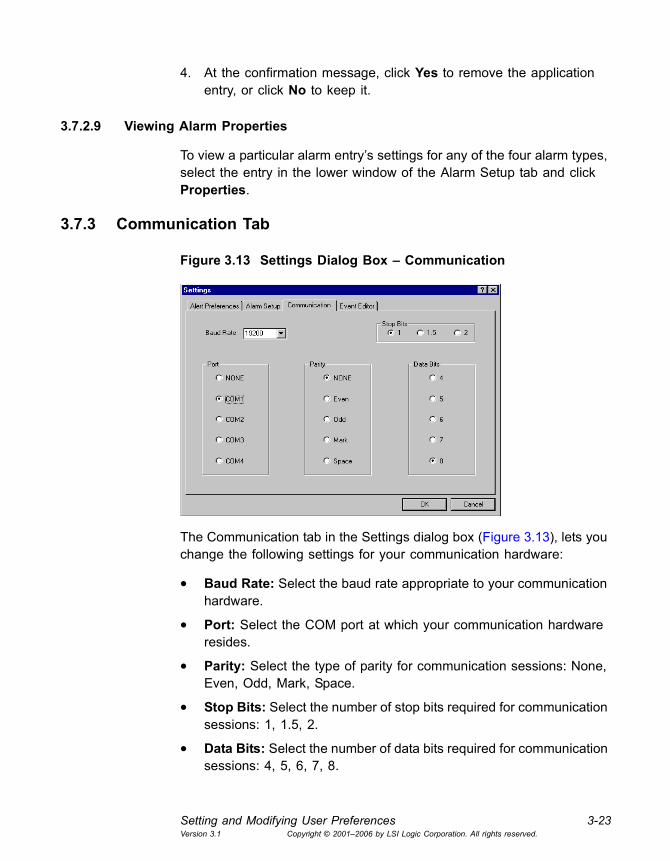
3.7.3 Communication Tab
Figure 3.13 Settings Dialog Box � Communication
The Communication tab in the Settings dialog box (Figure 3.13), lets you change the following settings for your communication hardware:
• Baud Rate: Select the baud rate appropriate to your communication hardware.
• Port: Select the COM port at which your communication hardware resides.
• Parity: Select the type of parity for communication sessions: None, Even, Odd, Mark, Space.
• Stop Bits: Select the number of stop bits required for communication sessions: 1, 1.5, 2.
• Data Bits: Select the number of data bits required for communication sessions: 4, 5, 6, 7, 8.

3-24 Startup, Overview, and SetupVersion 3.1 Copyright © 2001�2006 by LSI Logic Corporation. All rights reserved.
After you change the settings on this tab, click OK to save the changes and exit, or click Cancel to exit without saving, or click another Settings tab to continue working.
3.7.4 Event Editor Tab
Figure 3.14 Settings Dialog Box � Event Editor
The Event Editor tab in the Settings dialog box (Figure 3.14), allows you to change the properties of selected events. (For a complete list of GAMTT events, see Appendix A, �Event and Message Information.�)
3.7.4.1 Changing Event Properties
To change event properties, follow these steps:
1. Select an Event ID to edit from the Event ID list box at the top of the tab.
2. Type your own number for this event in the User Event ID list box, or keep the default (equal to the Event ID number).
3. Type your own event severity level in the Severity list box, or keep the default (set by LSI Logic).
4. Click Default to return all settings for this particular event to their defaults.
Setting and Modifying User Preferences 3-25Version 3.1 Copyright © 2001�2006 by LSI Logic Corporation. All rights reserved.
5. When all Global boxes are checked, you can view the alarms that will activate when this particular event occurs (these are based on the settings in Alert Preferences). Check or uncheck specific boxes if you wish to override these defaults and change the alarms for this event.
6. In the Event Message Text field at the bottom of the dialog box, you can type new text for this event, or you can keep the default text (set by LSI Logic).
If you modify the event definitions, a data file called gam2cl.gef is automatically generated. This file is then read whenever GAMTT starts, and a dialog box is displayed to inform you about this.
The gam2cl.gef file defines all events, even for new releases of GAMTT that may have added new events. The new events will not be seen until the gam2cl.gef file is deleted and the GAMTT client is restarted.
3.7.4.2 Restoring GAMTT Defaults
Click Default All at the bottom of the Event Editor tab if you want to reset all events of all severity levels back to their LSI Logic defaults.
After you change the settings on this tab, click OK to save the changes and exit, or click Cancel to exit without saving, or click another Settings tab to continue working.

3-26 Startup, Overview, and SetupVersion 3.1 Copyright © 2001�2006 by LSI Logic Corporation. All rights reserved.
Global Array Manager Transition Tool Client Software User�s Guide 4-1Version 3.1 Copyright © 2001�2006 by LSI Logic Corporation. All rights reserved.
Chapter 4Configuration
This chapter explains how to use Global Array Management Client to create and configure storage configurations. This primarily means creating new disk arrays and logical disks for data storage. It also involves other tasks such as changing the configuration options of controllers and disk drives. This chapter contains the following sections:
• Section 4.1, �Introduction�
• Section 4.2, �Setting and Changing Controller Options�
• Section 4.3, �Modifying Physical Device Options�
• Section 4.4, �Running RAID Assist�
• Section 4.5, �Adding a Logical Drive on MegaRAID, SAS, and Mylex Controllers�
• Section 4.6, �Creating Hot Spares�
• Section 4.7, �Expanding Capacity�
• Section 4.8, �Deleting a Logical Drive�
• Section 4.9, �Migrating a RAID Level�
• Section 4.10, �Transporting a Disk Array (Mylex Controllers Only)�
• Section 4.11, �Clustering�
• Section 4.12, �Managing Channels�
• Section 4.13, �Spanning in GAMTT�
• Section 4.14, �Enable Spanning in GAMTT�
• Section 4.15, �Configuring a Spanned Disk Array�
• Section 4.16, �Loading a Configuration from Disk�
• Section 4.17, �Saving a Configuration to Disk�
• Section 4.18, �Creating Configurations on Integrated RAID Controllers�

4-2 ConfigurationVersion 3.1 Copyright © 2001�2006 by LSI Logic Corporation. All rights reserved.
4.1 Introduction
You use the Global Array Management Client RAID Assist wizard to create disk arrays and logical drives. RAID Assist can create simple configurations automatically. For more complex configurations, RAID Assist allows you to customize the configuration parameters according to your needs.
Note: The RAID Assist wizard works differently for some types of controllers. See Section 4.18, �Creating Configurations on Integrated RAID Controllers,� page 4-42, for instructions on configuring Integrated Mirroring and Integrated Mirroring Enhanced (IME) arrays on Ultra320 SCSI controllers. See Chapter 7, �Using GAMTT with Embedded MegaRAID Software,� for instructions on configuring arrays on MegaRAID SATA Software RAID.
The GAMTT Client Configuration Lock feature temporarily disables write access on a controller system during critical activities such as changing controller options, creating or deleting arrays, and clearing configurations. This prevents two or more users with administrator privileges from accidentally trying to change the same controller configurations at the same time.
Configuration Lock is activated when the first user initiates a critical activity such as expanding the capacity of an array. Other �administrator� users are locked out of that controller system until the critical activity is completed. The following message appears (Figure 4.1) when a Configuration Lock is in effect.
Figure 4.1 Configuration Lock Notification

Setting and Changing Controller Options 4-3Version 3.1 Copyright © 2001�2006 by LSI Logic Corporation. All rights reserved.
4.2 Setting and Changing Controller Options
To set and change Controller Options, select Administration -> Controller Options and change the entries in the Controller Options dialog box, as described in the following sections.
Note: This feature is not supported for Ultra320 SCSI controllers with IME arrays.
4.2.1 Controller Options Tab
To configure Controller Options, follow these steps:
1. Select the Controller Options tab (Figure 4.2).
Figure 4.2 Controller Options Dialog Box
2. Make changes as needed to any of the parameters listed on the tab.
3. Click the Advanced tab and make any changes to the parameters listed there. (See Section 4.2.2, �Advanced Controller Options Tab,� page 4-5.)
4. Click OK to accept the changes, or click Cancel to exit without saving.

4-4 ConfigurationVersion 3.1 Copyright © 2001�2006 by LSI Logic Corporation. All rights reserved.
Here are descriptions of the parameters on the Controller Options tab.
• Automatic Rebuild Management. Works together with SAF-TE disk array enclosures to detect removal of a failed drive and perform an automatic rebuild after a replacement drive is installed. To change the Rebuild rate, type a number in the Rate box or drag the slider control. The higher the number, the faster the Rebuild rate.
• Background Initialization
� Mylex Controllers: Allows logical drives to be initialized in the background, so that the logical drive is immediately available for use. If you disable this option, the logical drive cannot be used until it is fully initialized. To change the Initialization rate, type a number in the Rate box or drag the slider control. The higher the number, the faster the initialization rate.
� MegaRAID and SAS Controllers: Enable Background Initialization and initialization rate are supported. These controllers perform background initialization on the first write or after 5 minutes.
• Check Consistency Rate. A consistency check scans the consistency data on a fault tolerant logical drive to determine if the data has become corrupted. To change the Check Consistency rate, type a number in the Rate box or drag the slider control. The higher the number, the faster a consistency check will run. A number less than 50 causes more resources to be devoted to I/Os and consequently slows the consistency check process.
• MORE® Rate (Mylex Controllers only). MORE (Mylex Online RAID Expansion) enables you to increase the capacity of an existing online array by various means, such as adding disk drives or changing the RAID level. To change the MORE rate, type a number in the Rate box or drag the slider control. The higher the number, the faster the MORE rate. A number less than 50 causes more resources to be devoted to I/Os and consequently slows the MORE process.
• Auto Drive Sizing
� Mylex Controllers: Allows the software to set drives of a similar size (for example, 4.0 GB, 4.1 GB, 4.2 GB) to a common size automatically without editing the mylexdrv.siz file. This enables smoother operation by allowing drives of similar sizes to be treated as identical sizes for hot spares, replacement drives, and
Setting and Changing Controller Options 4-5Version 3.1 Copyright © 2001�2006 by LSI Logic Corporation. All rights reserved.
array drives. If Auto Drive Sizing is disabled, the software reads and uses the current contents of mylexdrv.siz.
Note: The mylexdrv.siz file is needed only for non-FSI controllers. The AcceleRAID 160, AcceleRAID 352, and eXtremeRAID 2000 controllers do not need this file.
� MegaRAID and SAS Controllers: Auto Drive Sizing is automatically enabled.
• Disk Spin-up. Only On Command drive spin-up is supported.
• Devices per Spins. Number of devices to spin up at one time. A low number lessens the likelihood of a power drain.
• Initial Delay. Number of seconds between physical device start-ups.
• Delay Between Spins. Number of seconds between consecutive device spin-up cycles.
• Clustering. Under Windows 2000/2003/XP 32-bit/95/98/Me with clustering support, clustering allows redundancy among controllers in various servers. If a controller or server fails, another controller can take over the disk drives and disk arrays that were formerly handled by the failed controller. This mechanism enables a �fault tolerance� among controllers and servers.
• Controller Host ID. Change this parameter if you want to set this controller�s target ID to something other than 7 (the default). This might be necessary to avoid a host ID conflict between two controllers that may be linked together from two clustered servers.
• Cache Line Size. This is the size of the data �chunk� that is read or written at one time. Valid cache line size values depend on the stripe size settings.
4.2.2 Advanced Controller Options Tab
To configure Advanced Controller Options, follow these steps:
1. Select the Advanced Controller Options tab (Figure 4.3).

4-6 ConfigurationVersion 3.1 Copyright © 2001�2006 by LSI Logic Corporation. All rights reserved.
Figure 4.3 Advanced Controller Options Dialog Box
2. Make changes as needed to any of the parameters listed on the tab.
3. Click OK to accept the changes, or click Cancel to exit without saving.
Here are descriptions of the parameters on the Advanced tab.
• Temporarily Offline RAID Array. When enabled, prevents a second physical drive associated with a currently critical system drive from being permanently marked offline. The disk drive is marked temporarily unavailable or dead. This feature is not supported for SAS controllers.
• Device Health Monitoring (S.M.A.R.T). When enabled, S.M.A.R.T. (Self-Monitoring Analysis and Reporting Technology) monitors the condition of drives and global and dedicated hot spare drives that are part of a RAID configuration group.
You can set the Polling Interval from 0�255 minutes, where 0 means that S.M.A.R.T. mode 6 is disabled.
• Patrol Read. When this option is enabled, the Patrol Read operation starts automatically on power up. Patrol Read periodically verifies all sectors, including the system reserved area in the RAID configured drives. It works for all RAID levels and standby drives. The patrol read is initiated only when the controller is idle for a defined period and has no other background activities.

Modifying Physical Device Options 4-7Version 3.1 Copyright © 2001�2006 by LSI Logic Corporation. All rights reserved.
Once enabled, Patrol Read assumes that all configured system drives will undergo patrol read sequentially. When all configured drives are �patrolled,� it repeats the operation continuously.
You can set the Patrol Read Iterations from four hours to 1016 hours in multiples of four hours.
• Fibre Channel Speed (Mylex eXtremeRAID 3000 Controllers Only): Manages three speeds of the fibre channel.
� Auto - Sets an Auto Negotiate speed for the host port(s) selected.
� 1Gb - Sets a 1 Gigabits/second speed for the host port(s) selected.
� 2Gb - Sets a 2 Gigabits/second speed for the host port(s) selected.
4.3 Modifying Physical Device Options
To modify physical device options, select Administration -> Physical Device Options to open the Physical Device Options dialog box (Figure 4.4).
Note: This feature is not supported for Ultra320 SCSI controllers with IME arrays.
Figure 4.4 Physical Device Options Dialog Box
4-8 ConfigurationVersion 3.1 Copyright © 2001�2006 by LSI Logic Corporation. All rights reserved.
The dialog box displays a list of disk drives and other physical devices connected to the currently selected controller, and it lists the following information about each device:
• Model number of the physical device (often includes drive size)
• Channel number and Target ID where this device resides on the controller
• Current Transfer Speed (in Mbytes/s) for the device
• Transfer Width (8 bits or 16 bits) for the device
• Tag Value (Mylex controllers only)
To change the Transfer Speed, Transfer Width, and/or Tag Value for one or more physical devices, follow these instructions:
1. Select one or more physical devices in the window by clicking in the Model column.
Current settings are displayed under Setting Options.
2. Change the Transfer Speed and/or Transfer Width, if desired, by selecting an available option in the drop-down list box.
3. Change the Tag Value (Mylex Controllers Only), if desired, by typing a new value in the Tag Value field.
4. Click OK to accept the changes and exit, or click Apply to accept the changes without exiting, or click Cancel to exit without accepting the changes.
If you selected multiple devices, all selected devices are changed to the values you specified.
4.4 Running RAID Assist
RAID Assist is the GAMTT Client�s �wizard� for setting up and configuring new logical drives and disk arrays.
Note: See Section 4.18, �Creating Configurations on Integrated RAID Controllers,� page 4-42, for information on configuring IME arrays and logical drives on Ultra320 SCSI controllers.
Running RAID Assist 4-9Version 3.1 Copyright © 2001�2006 by LSI Logic Corporation. All rights reserved.
The RAID Assist Auto Configuration option allows you to immediately configure all available drives into an optimal configuration. RAID Assist�s Assisted Configuration mode sets up a new array according to predefined parameters, and asks the user questions to gather the key information necessary to build the array.
If the configuration is more complex than what Auto or Assisted Configuration offers, the Manual Configuration option allows additional control over logical drive setup parameters.
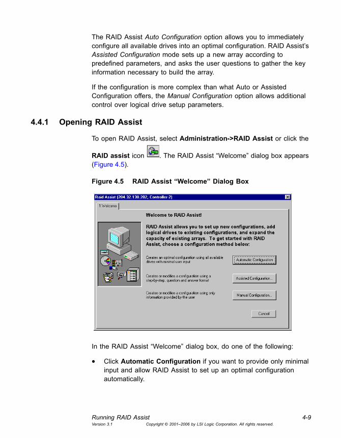
4.4.1 Opening RAID Assist
To open RAID Assist, select Administration->RAID Assist or click the
RAID assist icon . The RAID Assist �Welcome� dialog box appears (Figure 4.5).
Figure 4.5 RAID Assist �Welcome� Dialog Box
In the RAID Assist �Welcome� dialog box, do one of the following:
• Click Automatic Configuration if you want to provide only minimal input and allow RAID Assist to set up an optimal configuration automatically.

4-10 ConfigurationVersion 3.1 Copyright © 2001�2006 by LSI Logic Corporation. All rights reserved.
• Click Assisted Configuration if you want RAID Assist to lead you step-by-step through the configuration.
• Click Manual Configuration if you want full control over the configuration setup.
• Click Cancel if you want to exit RAID Assist without any changes.
4.4.2 Automatic Configuration
Automatic Configuration provides three options:
• New Configuration. Sets up a new configuration on the controller, deleting the previous configuration and data (if any).
• Add Logical Drive. Sets up additional arrays (logical drives) while leaving the existing array(s) intact. At least one array must be configured on this controller, and unconfigured drive space must be available.
• Expand Array. Restripes data in the array across additional, unconfigured drives to expand the capacity of the array.
For example, select New Configuration, as shown in Figure 4.6.
Figure 4.6 Select �New Configuration�
The new configuration is based on the total number of drives discovered by GAMTT. RAID Assist uses the maximum number of drives, provides
Running RAID Assist 4-11Version 3.1 Copyright © 2001�2006 by LSI Logic Corporation. All rights reserved.
a fault tolerant RAID level if possible, and creates a hot spare drive for drive failure protection. The number of logical drives created is dependent on the total number of available physical drives.
Note: A warning message appears if GAMTT detects drives of different sizes. The message advises you to use Manual Configuration to achieve an optimum configuration.
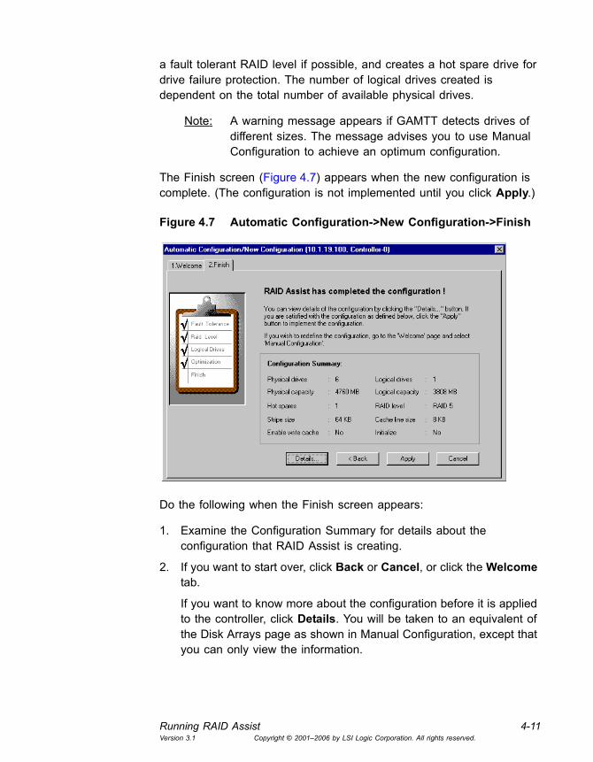
The Finish screen (Figure 4.7) appears when the new configuration is complete. (The configuration is not implemented until you click Apply.)
Figure 4.7 Automatic Configuration->New Configuration->Finish
Do the following when the Finish screen appears:
1. Examine the Configuration Summary for details about the configuration that RAID Assist is creating.
2. If you want to start over, click Back or Cancel, or click the Welcome tab.
If you want to know more about the configuration before it is applied to the controller, click Details. You will be taken to an equivalent of the Disk Arrays page as shown in Manual Configuration, except that you can only view the information.

4-12 ConfigurationVersion 3.1 Copyright © 2001�2006 by LSI Logic Corporation. All rights reserved.
3. To accept the configuration as presented, click Apply on the Finish screen.
A warning confirmation box appears.
4. Type YES and click OK if you are sure you want to apply the new configuration and overwrite the old one. If you�re not sure, click Cancel.
4.4.3 Assisted Configuration
You have these three options if you select Assisted Configuration on the RAID Assist opening screen:
• New Configuration. Sets up a new configuration on the controller, deleting the previous configuration and data (if any).
• Add Logical Drive. Sets up additional arrays (logical drives) leaving the existing array(s) intact. At least one array must be configured on this controller, and unconfigured drive space must remain.
• Expand Array. Restripes data in the array across additional, unconfigured drives to expand the capacity of the array.
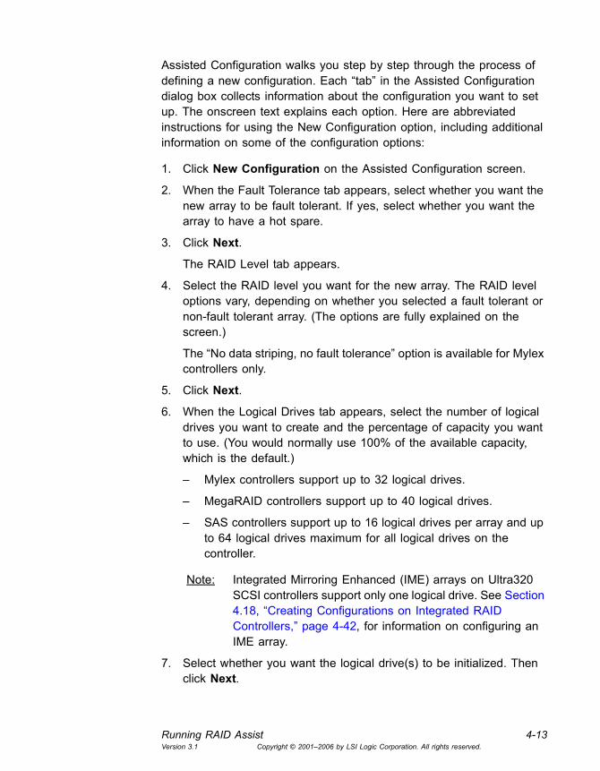
For example, select New Configuration, as shown in Figure 4.8:
Figure 4.8 Select �New Configuration�
Running RAID Assist 4-13Version 3.1 Copyright © 2001�2006 by LSI Logic Corporation. All rights reserved.
Assisted Configuration walks you step by step through the process of defining a new configuration. Each �tab� in the Assisted Configuration dialog box collects information about the configuration you want to set up. The onscreen text explains each option. Here are abbreviated instructions for using the New Configuration option, including additional information on some of the configuration options:
1. Click New Configuration on the Assisted Configuration screen.
2. When the Fault Tolerance tab appears, select whether you want the new array to be fault tolerant. If yes, select whether you want the array to have a hot spare.
3. Click Next.
The RAID Level tab appears.
4. Select the RAID level you want for the new array. The RAID level options vary, depending on whether you selected a fault tolerant or non-fault tolerant array. (The options are fully explained on the screen.)
The �No data striping, no fault tolerance� option is available for Mylex controllers only.
5. Click Next.
6. When the Logical Drives tab appears, select the number of logical drives you want to create and the percentage of capacity you want to use. (You would normally use 100% of the available capacity, which is the default.)
� Mylex controllers support up to 32 logical drives.
� MegaRAID controllers support up to 40 logical drives.
� SAS controllers support up to 16 logical drives per array and up to 64 logical drives maximum for all logical drives on the controller.
Note: Integrated Mirroring Enhanced (IME) arrays on Ultra320 SCSI controllers support only one logical drive. See Section 4.18, �Creating Configurations on Integrated RAID Controllers,� page 4-42, for information on configuring an IME array.
7. Select whether you want the logical drive(s) to be initialized. Then click Next.

4-14 ConfigurationVersion 3.1 Copyright © 2001�2006 by LSI Logic Corporation. All rights reserved.
For most types of controllers, the logical drives are initialized in the foreground after the array configuration is applied, and you must wait until the configuration is done to use the logical drives. However, some types of Mylex controllers allow the new drives to be initialized in the background so you can start using them immediately after configuration.
If you selected Yes for initializing logical drives, and if the controller supports background initialization, the screen shown in Figure 4.9 appears.
Figure 4.9 Background Initialization is Supported
8. If this message appears, click No to have the drives initialized in the background. When you complete and apply the configuration, the logical drives will be available for immediate use.
Or click Yes to request a full foreground initialization of the logical drives once the new configuration is applied.
9. When the Optimization screen appears, select whether you want write cache support to be enabled or disabled. Select a stripe size and (for Mylex controllers only) a cache line size.
Valid cache line size values depend on the stripe size settings. If you select a cache line size of 64 KB and you choose a stripe size lower than 64 KB, a Warning dialog box appears with the following message, �Due to your selection of Stripe Size less than 64KB, 8KB Cache Line Size will be used.�
10. Click Next. The Finish screen appears (Figure 4.10).
Note: A warning message appears if GAMTT detects drives of different sizes. The message advises you to use Manual Configuration to achieve an optimum configuration.
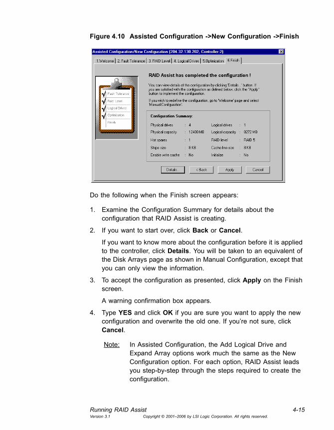
Running RAID Assist 4-15Version 3.1 Copyright © 2001�2006 by LSI Logic Corporation. All rights reserved.
Figure 4.10 Assisted Configuration ->New Configuration ->Finish
Do the following when the Finish screen appears:
1. Examine the Configuration Summary for details about the configuration that RAID Assist is creating.
2. If you want to start over, click Back or Cancel.
If you want to know more about the configuration before it is applied to the controller, click Details. You will be taken to an equivalent of the Disk Arrays page as shown in Manual Configuration, except that you can only view the information.
3. To accept the configuration as presented, click Apply on the Finish screen.
A warning confirmation box appears.
4. Type YES and click OK if you are sure you want to apply the new configuration and overwrite the old one. If you�re not sure, click Cancel.
Note: In Assisted Configuration, the Add Logical Drive and Expand Array options work much the same as the New Configuration option. For each option, RAID Assist leads you step-by-step through the steps required to create the configuration.

4-16 ConfigurationVersion 3.1 Copyright © 2001�2006 by LSI Logic Corporation. All rights reserved.
4.4.4 Manual Configuration
Manual Configuration provides these options:
• Edit Configuration. Displays the current configuration (disk arrays and logical drives) and allows you to add or delete logical drives randomly. This operation, called Random Add or Delete a Logical Drive(s), does not affect any other existing logical drive data, but it may cause an available space to be segmented. If you delete a logical drive, data on the edited logical drive(s) is lost.
• New Configuration. Sets up a new configuration on the controller, deleting the previous configuration and data (if any).
• Add Logical Drive. Adds a logical drive randomly leaving the existing array(s) intact. At least one array must be configured on this controller, and unconfigured drive space must be available. (See Section 4.5, �Adding a Logical Drive on MegaRAID, SAS, and Mylex Controllers.�)
• Expand Array. Restripes data in the array across additional, unconfigured drives to expand the capacity of the array. MORE2 and RAID Level Migration functions are available here. (See Section 4.7, �Expanding Capacity.�)
• Defragment Array (Mylex Controllers Only). Defragments unused space in an existing array. (See Section 6.5, �Defragmenting an Array (Mylex Controllers Only).�)
For example, select New Configuration, as shown in Figure 4.11.

Running RAID Assist 4-17Version 3.1 Copyright © 2001�2006 by LSI Logic Corporation. All rights reserved.
Figure 4.11 Select �New Configuration�
The Disk Arrays tab in Manual Configuration is where you begin to configure the unused disk drives, shown in the lower left corner of Figure 4.12.
Figure 4.12 Manual Configuration � Disk Arrays
Each disk array is represented by a grid of spaces for disk drive icons in the Disk Arrays area of the screen (upper left, Figure 4.12). Logical
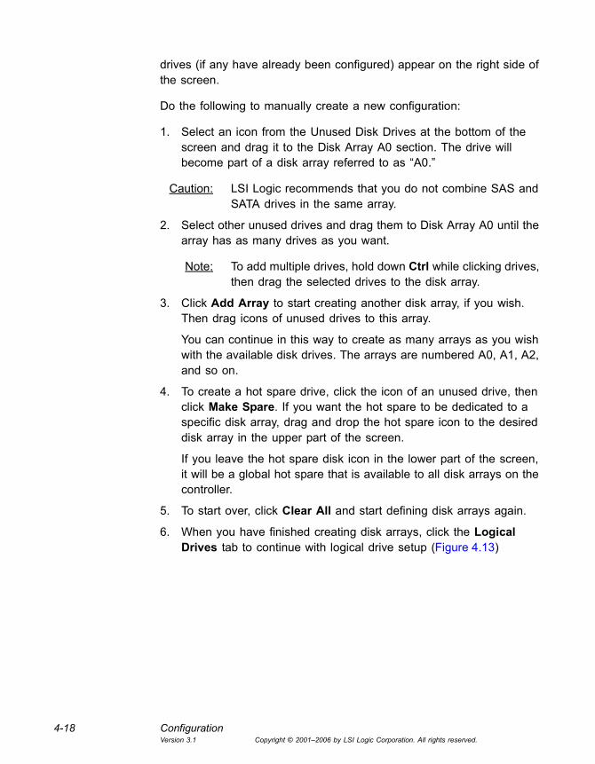
4-18 ConfigurationVersion 3.1 Copyright © 2001�2006 by LSI Logic Corporation. All rights reserved.
drives (if any have already been configured) appear on the right side of the screen.
Do the following to manually create a new configuration:
1. Select an icon from the Unused Disk Drives at the bottom of the screen and drag it to the Disk Array A0 section. The drive will become part of a disk array referred to as �A0.�
Caution: LSI Logic recommends that you do not combine SAS and SATA drives in the same array.
2. Select other unused drives and drag them to Disk Array A0 until the array has as many drives as you want.
Note: To add multiple drives, hold down Ctrl while clicking drives, then drag the selected drives to the disk array.
3. Click Add Array to start creating another disk array, if you wish. Then drag icons of unused drives to this array.
You can continue in this way to create as many arrays as you wish with the available disk drives. The arrays are numbered A0, A1, A2, and so on.
4. To create a hot spare drive, click the icon of an unused drive, then click Make Spare. If you want the hot spare to be dedicated to a specific disk array, drag and drop the hot spare icon to the desired disk array in the upper part of the screen.
If you leave the hot spare disk icon in the lower part of the screen, it will be a global hot spare that is available to all disk arrays on the controller.
5. To start over, click Clear All and start defining disk arrays again.
6. When you have finished creating disk arrays, click the Logical Drives tab to continue with logical drive setup (Figure 4.13)

Running RAID Assist 4-19Version 3.1 Copyright © 2001�2006 by LSI Logic Corporation. All rights reserved.
Figure 4.13 Manual Configuration � Logical Drives
The Logical Drives tab in Manual Configuration is where you configure the disk arrays into logical drives.
Do the following to configure logical drives:
1. To randomly create a logical drive, select the desired disk array from the Disk Array drop down menu (Mylex controllers only).
2. Select a RAID level for the first logical drive. Only RAID levels compatible with the current configuration are available in the list.
� Mylex controllers support RAID 0, RAID 1, RAID 3, RAID 5, RAID 10, and stand-alone drive (JBOD) configurations.
� MegaRAID and SAS controllers support RAID 0, RAID 1, RAID 5, RAID 10, and RAID 50 configurations.
3. Type the amount of available logical or physical capacity for this logical drive. Do not change the default sizes if the total configuration will have only one logical drive that uses all available capacity. If you intend to create additional logical drives now or later, type a smaller number to reserve the desired amount of capacity.
Note: When creating a random logical drive, if there are a few existing segmented spaces, the largest space is used to create the logical drive.
4. Check the Write Cache box if you want this logical drive to use Write Back caching. This improves performance but puts data at risk. You

4-20 ConfigurationVersion 3.1 Copyright © 2001�2006 by LSI Logic Corporation. All rights reserved.
should not select this feature unless you have a battery backup unit or uninterruptible power supply.
5. Check the Init Drive box if you want this logical drive to be fully initialized at the conclusion of the configuration. It is recommended that you check this option (if available), unless the controller is capable of background initialization. If so, and you check the box, you�ll see a message when you apply the configuration indicating that you can make use of the background initialization feature.
6. Select a stripe size. The stripe size is defined as the size, in KBytes, of a single I/O operation. A stripe of data (data residing in actual physical disk sectors, which are logically ordered first to last) is divided over all disks in the drive group.
When selecting a stripe size of less than 64 KB, the active cache line size changes from 64 KB to 8 KB. A Warning dialog box appears with the following message, �Due to a Stripe Size selection of less than 64KB, 8KB Cache Line Size will be used.�
If you select Yes, the new configuration is applied and an 8 KB cache line size is active.
If you select No, the Logical Drives page of the Manual Configuration Wizard opens. You can change the stripe size in order to obtain the desired cache line size.
7. Select a cache line size (Mylex controllers only), if enabled. Available settings depend on the selected stripe size.
8. Select a Read Control option: Normal, Ahead, or Adaptive.
Select Ahead to enable read-ahead capability for the logical drive, or select Normal (the default) to disable it. Read-ahead capability allows the controller to read sequentially ahead of requested data and to store the additional data in cache memory, anticipating that the data will be needed soon. This speeds up reads for sequential data, but there is little improvement when accessing random data. If you select Adaptive, the controller begins using read-ahead if the two most recent disk accesses occurred in sequential sectors. If the read requests are random, the controller reverts to Normal (read-ahead disabled).
9. (Optional) Select the Direct I/O check box to enable Direct I/O capability.
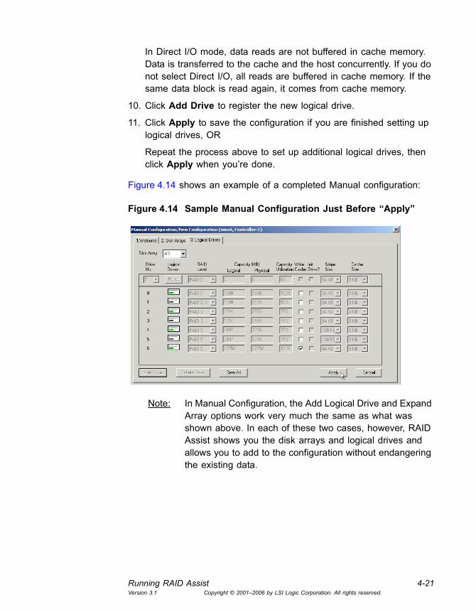
Running RAID Assist 4-21Version 3.1 Copyright © 2001�2006 by LSI Logic Corporation. All rights reserved.
In Direct I/O mode, data reads are not buffered in cache memory. Data is transferred to the cache and the host concurrently. If you do not select Direct I/O, all reads are buffered in cache memory. If the same data block is read again, it comes from cache memory.
10. Click Add Drive to register the new logical drive.
11. Click Apply to save the configuration if you are finished setting up logical drives, OR
Repeat the process above to set up additional logical drives, then click Apply when you�re done.
Figure 4.14 shows an example of a completed Manual configuration:
Figure 4.14 Sample Manual Configuration Just Before �Apply�
Note: In Manual Configuration, the Add Logical Drive and Expand Array options work very much the same as what was shown above. In each of these two cases, however, RAID Assist shows you the disk arrays and logical drives and allows you to add to the configuration without endangering the existing data.

4-22 ConfigurationVersion 3.1 Copyright © 2001�2006 by LSI Logic Corporation. All rights reserved.
4.5 Adding a Logical Drive on MegaRAID, SAS, and Mylex Controllers
Adding a logical drive utilizes available space in an existing array or allows for creation of a new array using unconfigured disk drives while normal reads and writes occur. Existing data is not affected by this procedure.
Note: This feature is not supported for Ultra320 SCSI controllers with IME arrays.
To add a logical drive, follow these steps:
1. Select a controller.
2. Select Administration->RAID Assist on the menu bar, or click the
RAID Assist icon .
3. Click Manual Configuration.
4. Click Add Logical Drive. The Logical Drives tab appears (see Figure 4.15).
Figure 4.15 Logical Drives Tab
5. Select a RAID level for the new logical drive.
6. Type the desired amount of available logical or physical capacity for this logical drive.

Creating Hot Spares 4-23Version 3.1 Copyright © 2001�2006 by LSI Logic Corporation. All rights reserved.
Figure 4.16 Add Logical Drive(s)
7. Check the Write Cache box if you want this logical drive to use Write Back caching. This improves performance but puts data at risk. You should select this feature only if the controller has a battery backup unit or uninterruptible power supply.
8. Check the Init Drive box if you want this logical drive to be fully initialized at the conclusion of the configuration.
9. Select a stripe size.
10. Select a cache line size, if enabled. Available settings depend on the selected stripe size.
11. Click Add Drive.
12. Add other logical drives, if desired.
13. Click Apply to save the new configuration.
A warning confirmation box appears.
14. Type YES and click OK if you are sure you want to apply the new configuration and overwrite the old.
4.6 Creating Hot Spares
There are two kinds of hot spares: 1) dedicated hot spare and 2) global hot spare. A dedicated hot spare belongs to a single disk array or spanned disk array. A global hot spare can replace a failed disk on any disk array within Private or Shared channel boundaries.
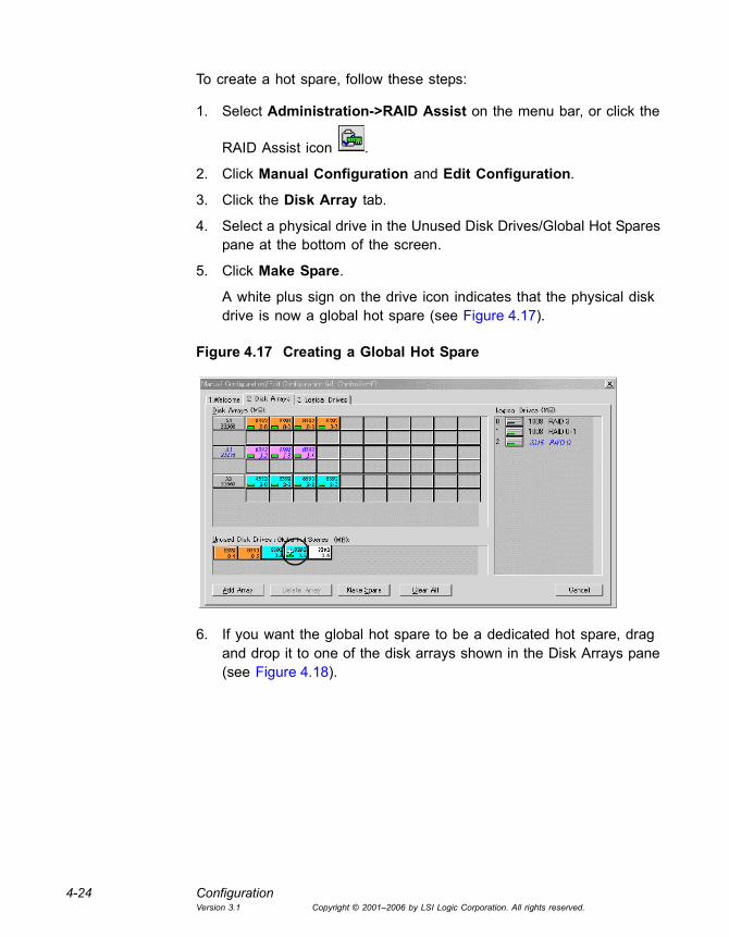
4-24 ConfigurationVersion 3.1 Copyright © 2001�2006 by LSI Logic Corporation. All rights reserved.
To create a hot spare, follow these steps:
1. Select Administration->RAID Assist on the menu bar, or click the
RAID Assist icon .
2. Click Manual Configuration and Edit Configuration.
3. Click the Disk Array tab.
4. Select a physical drive in the Unused Disk Drives/Global Hot Spares pane at the bottom of the screen.
5. Click Make Spare.
A white plus sign on the drive icon indicates that the physical disk drive is now a global hot spare (see Figure 4.17).
Figure 4.17 Creating a Global Hot Spare
6. If you want the global hot spare to be a dedicated hot spare, drag and drop it to one of the disk arrays shown in the Disk Arrays pane (see Figure 4.18).

Expanding Capacity 4-25Version 3.1 Copyright © 2001�2006 by LSI Logic Corporation. All rights reserved.
Figure 4.18 Creating a Dedicated Hot Spare
The global hot spare becomes a dedicated hot spare, as indicated by the green plus sign on the disk icon.
Note: Only global hot spares are supported for IME arrays on Ultra320 SCSI controllers.
4.7 Expanding Capacity
GAMTT enables you to expand the capacity of an existing storage configuration by adding physical and logical drives. On Mylex controllers you can also increase the size of an existing logical drive or change its RAID level.
Caution: If any rebuilds or consistency checks are running, be sure to let them complete before you expand a storage configuration. Also, be sure to back up user data before you expand the storage configuration.
As explained in the following sections, capacity expansion is done differently on Mylex controllers than on other types of controllers.
4.7.1 Expanding Capacity on Mylex Controllers
You can expand storage capacity on a Mylex controller by adding physical drives to increase the size of an existing logical drive. You can also change the RAID level, increase the amount of space allocated to

4-26 ConfigurationVersion 3.1 Copyright © 2001�2006 by LSI Logic Corporation. All rights reserved.
a logical drive, or create new logical drives. When performing this operation, you cannot change the stripe size of an existing logical drive.
Capacity expansion operations on Mylex controllers have the following restrictions:
• Channel swapping is not allowed during the capacity expansion.
• No capacity expansion operations are allowed on a spanned array.
• The resulting configuration after the capacity expansion may not exceed 16 physical disks.
Added capacity amounts are rounded up to the next whole Mbyte on the physical drives. This means that the space is allocated on the physical drives with one Mbyte granularity. An existing array can be expanded to a maximum of 32 drives.
Caution: You should back up the data and current configuration before you expand an array.
To perform an Array Expansion, follow these steps:
1. Select a controller.
2. Select Administration->RAID Assist on the menu bar, or click the
RAID Assist icon .
3. Click Manual Configuration.
4. Click Expand Array. The Manual Configuration Disk Array tab opens (see Figure 4.19). This is where you can add available disk drive capacity.
5. Select the physical drives that you want to add to the array and drag and drop them to the desired array (see Figure 4.19).

Expanding Capacity 4-27Version 3.1 Copyright © 2001�2006 by LSI Logic Corporation. All rights reserved.
Figure 4.19 Adding Physical Drives to an Array
6. Click the Logical Drives tab.
Figure 4.20 Logical Drives Tab
7. From the Physical Capacity drop-down list, select the maximum amount of capacity.
8. Add the maximum capacity, or a portion of it, to the logical drive.

4-28 ConfigurationVersion 3.1 Copyright © 2001�2006 by LSI Logic Corporation. All rights reserved.
� To add a portion of the capacity: type the desired capacity amount in the Logical Drive Capacity field.
� To add the entire amount of capacity: select the amount from the Physical capacity drop-down list.
9. (Optional) Change the RAID level.
10. Click Apply to save the new configuration.
A message box appears warning you that the array changes cannot be reversed.
11. Click Yes to proceed.
Another warning confirmation box appears.
12. Type YES and click OK if you are sure you want to apply the new configuration and overwrite the old one.
WARNING: The Expand Capacity process cannot be cancelled.
The Expand Capacity Status box opens and displays the progress of the disk array capacity expansion.
13. Click Close to close the Expand Capacity Status box at any time. Click View-> Expand Capacity Status to open the status box at any time.
4.7.2 Expanding an Array on MegaRAID and SAS Controllers
You can expand an existing array on a MegaRAID or SAS controller by adding physical drives and creating a larger logical drive. The existing array can be expanded to a maximum of 40 drives.
Caution: You should not combine SAS and SATA drives in the same array. You should back up the data and the current configuration before you expand the array.
To perform an Array Expansion, follow these steps:
1. Select Administration->RAID Assist on the menu bar, or click the
RAID Assist icon .
2. Click Manual Configuration.
3. Click Expand Array.
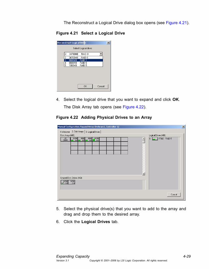
Expanding Capacity 4-29Version 3.1 Copyright © 2001�2006 by LSI Logic Corporation. All rights reserved.
The Reconstruct a Logical Drive dialog box opens (see Figure 4.21).
Figure 4.21 Select a Logical Drive
4. Select the logical drive that you want to expand and click OK.
The Disk Array tab opens (see Figure 4.22).
Figure 4.22 Adding Physical Drives to an Array
5. Select the physical drive(s) that you want to add to the array and drag and drop them to the desired array.
6. Click the Logical Drives tab.

4-30 ConfigurationVersion 3.1 Copyright © 2001�2006 by LSI Logic Corporation. All rights reserved.
Figure 4.23 Logical Drives Tab
7. Add logical drives to utilize the new capacity.
8. Click Apply to save the new configuration.
A message box appears warning you that the array changes cannot be reversed.
9. Click Yes to proceed:
Another warning confirmation box appears.
10. Type YES and click OK if you are sure you want to apply the new configuration and overwrite the old one.
WARNING: Expand Capacity cannot be cancelled.
The Expand Capacity Status box opens and displays the progress of the disk array capacity expansion.
11. Click Close to close the Expand Capacity Status box at any time. Click View-> Expand Capacity Status to open the status box at any time.

Deleting a Logical Drive 4-31Version 3.1 Copyright © 2001�2006 by LSI Logic Corporation. All rights reserved.
4.8 Deleting a Logical Drive
This function allows you to remove one or more logical drives for the purpose of rearranging the storage space. To delete a logical drive, follow these steps:
1. Back up all user data on the array(s) you intend to delete.
2. Select Administration->RAID Assist on the menu bar, or click the
RAID Assist icon .
3. Click Manual Configuration, then Edit Configuration.
4. Select the Logical Drives tab (see Figure 4.24).
Figure 4.24 Deleting a Logical Drive
5. To delete a logical drive:
� For Mylex controllers, you must first right-click the logical drive that you want to delete. This activates the Delete Drive button.
� For MegaRAID and SAS controllers, the last logical drive created is the first deleted, and so on.
6. Click Delete Drive. The logical drive is deleted from the configuration.
7. Repeat Step 5 and Step 6 to delete more logical drives, if desired.
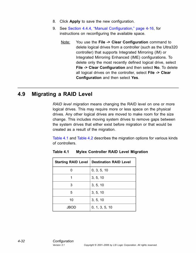
4-32 ConfigurationVersion 3.1 Copyright © 2001�2006 by LSI Logic Corporation. All rights reserved.
8. Click Apply to save the new configuration.
9. See Section 4.4.4, �Manual Configuration,� page 4-16, for instructions on reconfiguring the available space.
Note: You use the File -> Clear Configuration command to delete logical drives from a controller (such as the Ultra320 controller) that supports Integrated Mirroring (IM) or Integrated Mirroring Enhanced (IME) configurations. To delete only the most recently defined logical drive, select File -> Clear Configuration and then select No. To delete all logical drives on the controller, select File -> Clear Configuration and then select Yes.
4.9 Migrating a RAID Level
RAID level migration means changing the RAID level on one or more logical drives. This may require more or less space on the physical drives. Any other logical drives are moved to make room for the size change. This includes moving system drives to remove gaps between the system drives that either exist before migration or that would be created as a result of the migration.
Table 4.1 and Table 4.2 describes the migration options for various kinds of controllers.
Table 4.1 Mylex Controller RAID Level Migration
Starting RAID Level Destination RAID Level
0 0, 3, 5, 10
1 3, 5, 10
3 3, 5, 10
5 3, 5, 10
10 3, 5, 10
JBOD 0, 1, 3, 5, 10

Transporting a Disk Array (Mylex Controllers Only) 4-33Version 3.1 Copyright © 2001�2006 by LSI Logic Corporation. All rights reserved.
Note: RAID level migration is not supported for Ultra320 SCSI controllers with IM and IME arrays.
To migrate a RAID level, follow these steps:
1. Select Administration->RAID Assist on the menu bar, or click the
RAID Assist icon .
2. Click Manual Configuration/Edit Configuration.
3. Click the Logical Drives tab. This is where you can edit a RAID level.
4. Follow Step 5 through Step 14 of Section 4.7.1, �Expanding Capacity on Mylex Controllers,� page 4-25 or Section 4.7.2, �Expanding an Array on MegaRAID and SAS Controllers,� page 4-28.
4.10 Transporting a Disk Array (Mylex Controllers Only)
You can transport a the physical drives in disk array between any single controller and any dual controllers, and vice versa. However, in order to do this, you need to know which disk drives in an enclosure belongs to which specific disk array. To help you, the Locate function flashes LEDs on disk drives to indicate which drives are members of a specific array.
To locate a disk array in order to transport it, follow these steps:
1. In the Controller View window, double click a logical drive.
The Logical Drive Information window opens (see Figure 4.25).
Table 4.2 MegaRAID and SAS Controller RAID Level Migration
Starting RAID Level Destination RAID Level
0 0, 1, 5
1 0, 5
5 0, 5

4-34 ConfigurationVersion 3.1 Copyright © 2001�2006 by LSI Logic Corporation. All rights reserved.
Figure 4.25 Logical Drive Information Window � Transport Button
2. Click Transport. The Disk Array Transport Information window opens (Figure 4.26).
Figure 4.26 Disk Array Transport Information Window
All physical drives are displayed, including the global and dedicated spares associated with the selected logical drive and all logical drives that belong to the same disk array.

Clustering 4-35Version 3.1 Copyright © 2001�2006 by LSI Logic Corporation. All rights reserved.
3. Click Locate Transport to turn on LEDs on all of the physical drives, including the global and dedicated hot spares that belong to the disk array.
4. Note which disk drives have the blinking LEDs.
You are now ready to remove and transport the physical drives.
4.11 Clustering
In a clustered RAID environment, multiple Mylex, SAS, and MegaRAID controllers share the same back end SCSI disk drives through a SCSI or Fibre channel cable(s). If the controllers reside on different systems, respectively, it is called clustering.
A clustering software program manages the clustering configuration.
4.12 Managing Channels
After you create a clustering configuration, you may experience a �Boot Failure� if you create an array using disks from different channels. To help you avoid this, a different color is used for disks on each channel. The colors are as follows:
• Channel 0: Orange
• Channel 1: Violet
• Channel 2: Cyan
• Channel 3: Lavender
Note: The use of colors when managing channels is available only for Mylex controllers. The channel colors listed are subject to change.
A channel that is not shared with any other controller is called a private channel. A channel that is shared with cluster nodes is called a shared channel. To indicate the type of channel, the following colors of text are used:
• Private Channel: black text in normal font

4-36 ConfigurationVersion 3.1 Copyright © 2001�2006 by LSI Logic Corporation. All rights reserved.
• Shared Channel: blue text in italic font
For example, Figure 4.27 shows the Disk Array tab where a controller has four channels. Channel 1 is a shared channel and the other three channels are private channels. Because Channel 1 is a shared channel, all text associated with the channel is blue and italicized (physical disk numbers, an array number, and a logical number).
Figure 4.27 Disk Array Tab � Four Channels Displayed
Figure 4.28 shows the Controller View window displaying four channels.
Figure 4.28 Controller View � Four Channels Displayed

Spanning in GAMTT 4-37Version 3.1 Copyright © 2001�2006 by LSI Logic Corporation. All rights reserved.
When you try to create a disk array across channels, a caution message appears to warn you of this. The message does not stop you from creating the array, however. Click OK to continue, or click Cancel to end the operation. When GAMTT Client is running, this message appears once at the first attempt.
If intermixing of drives between Private and Shared channels occurs during configuration, the operation is inhibited and a warning message is displayed.
4.13 Spanning in GAMTT
Spanning allows you to configure multiple drive packs or parts of multiple drive packs as one system drive. This means that space is used from the first array to the last identical array.
A drive pack is a group of individual disk drives (preferably identical) that are logically tied to each other and are addressed as a single unit. In some cases, this may be called a drive �pack� when referring to just the physical devices.
All physical devices in a drive group should be the same size; otherwise, all disks in the group will have the capacity of the smallest disk. The total size of the drive group is the size of the smallest disk in the group multiplied by the number of disks in the group. For example, if you have four 400 Mbyte disks and one 200 Mbyte disk in a pack, the effective available capacity is only 1000 Mbytes (5x200), not 1800 Mbytes.
Drive packs or groups have the following properties.
• From one to sixteen disk drives included in an individual drive pack or group.
• The drive pack can include physical disk drives located on different drive channels.
• The number of disk drives in a drive pack determines the possible RAID level. Use the following tables to configure a spanned array:

4-38 ConfigurationVersion 3.1 Copyright © 2001�2006 by LSI Logic Corporation. All rights reserved.
Mylex Controllers: To create a JBOD or RAID 0, RAID 1, RAID 3, RAID 5, or RAID 10 spanned array, use Table 4.3:
MegaRAID or SAS Controllers: To create a RAID 0, RAID 1, or RAID 5 spanned array, use Table 4.4:
After physical disk drive packs are defined, one or more system drives may be created from them. System drives have the following properties:
• In GAMTT more than one system drive can be defined on a single drive pack; a system drive can also span 16 packs.
• The minimum size of a system drive is 8 Mbytes. The maximum is 2 Terabytes.
• Up to 32 system drives can be created. Each system drive has its own write policy (write-back or write-through).
Table 4.3 Configuring a Spanned Array with Mylex Controllers
RAID Level
Minimum # of Drives
Maximum # of Drives
Maximum # of Drives with Spanning Enabled
Theoretical Maximum # of Drives
0 1 16 256 256
1 2 2 32 256
3 3 16 256 256
5 3 16 256 256
10 3 16 256 16
Table 4.4 Configuring a Spanned Array with MegaRAID or SAS Controllers
RAID Level
Minimum # of Drives
Maximum # of Drives
Maximum # of Drives with Spanning Enabled
Theoretical Maximum # of Drives
0 1 32 256 256
1 2 2 16 16
5 3 32 256 256
Enable Spanning in GAMTT 4-39Version 3.1 Copyright © 2001�2006 by LSI Logic Corporation. All rights reserved.
4.14 Enable Spanning in GAMTT
Before you can create spanned drives in GAMTT, you must enable spanning by following these steps:
1. Using a text editor application (such as Notepad), open the gam2cl.ini file.
2. Scroll to the Enable_System_Drive_Span=0 parameter and set the parameter to 1 (default value =0).
3. Save and close the gam2cl.ini file.
4.15 Configuring a Spanned Disk Array
Follow these steps to configure a spanned disk array:
1. Select Administration->RAID Assist on the menu bar, or click the
RAID Assist icon .
2. Click Manual Configuration.
3. Click Edit Configuration.
Note: The Automatic and Assisted configuration options do not allow spanning.
4. To create a RAID 1 or RAID 0 spanned disk array, connect at least four drives of the same size to a controller. To create a RAID 3, RAID 5, or RAID 10 spanned disk array, connect at least six drives of the same size to a controller.
5. Select physical drives from the drive packs to create a spanned array. Use the same number of devices in each array, or spanning will not be utilized. Figure 4.29 shows the creation of three arrays, each with the same number of equal sized disk drives.
4.15.1 Creating a Spanned Disk Array
Follow these steps to create a spanned disk array:
Note: Spanned disk arrays cannot be created across a private channel and a shared channel.
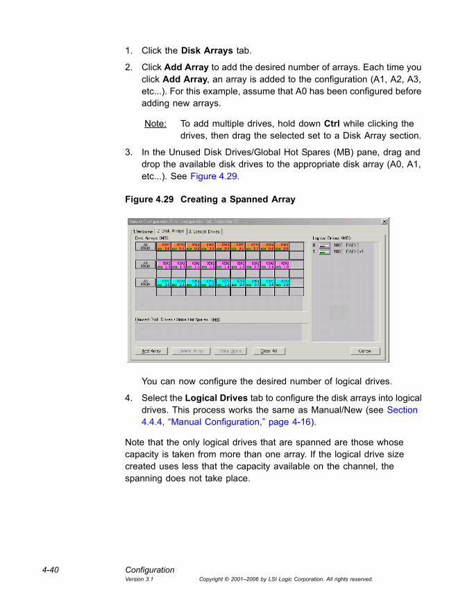
4-40 ConfigurationVersion 3.1 Copyright © 2001�2006 by LSI Logic Corporation. All rights reserved.
1. Click the Disk Arrays tab.
2. Click Add Array to add the desired number of arrays. Each time you click Add Array, an array is added to the configuration (A1, A2, A3, etc...). For this example, assume that A0 has been configured before adding new arrays.
Note: To add multiple drives, hold down Ctrl while clicking the drives, then drag the selected set to a Disk Array section.
3. In the Unused Disk Drives/Global Hot Spares (MB) pane, drag and drop the available disk drives to the appropriate disk array (A0, A1, etc...). See Figure 4.29.
Figure 4.29 Creating a Spanned Array
You can now configure the desired number of logical drives.
4. Select the Logical Drives tab to configure the disk arrays into logical drives. This process works the same as Manual/New (see Section 4.4.4, �Manual Configuration,� page 4-16).
Note that the only logical drives that are spanned are those whose capacity is taken from more than one array. If the logical drive size created uses less that the capacity available on the channel, the spanning does not take place.

Loading a Configuration from Disk 4-41Version 3.1 Copyright © 2001�2006 by LSI Logic Corporation. All rights reserved.
4.16 Loading a Configuration from Disk
When you replace a controller, or when you want to duplicate an existing configuration on a new controller, you can apply a saved configuration to the controller. To apply a saved configuration, follow these steps:
1. Select a controller.
2. Select Open Configuration from the File menu.
3. Select the configuration file and click Open.
4. View the configuration detail, then select Apply.
5. Confirm the new configuration when prompted.
Note
• This feature is not supported for IME arrays on Ultra320 SCSI controllers.
WARNING
• When copying a saved configuration to a replacement controller, be sure the saved configuration is correct. Applying an out-of-date or incorrect configuration to a replacement controller will cause loss of access to data associated with the controller.
4.17 Saving a Configuration to Disk
Note: This feature is not supported for Ultra320 SCSI controllers with IME arrays.
To save a configuration file to a new filename, disk, and/or directory, follow these steps:
1. Select File -> Save Configuration.
2. In the Save Configuration dialog box, type a name for the configuration file you want to save.
3. Click Save to save the configuration file.
The configuration file (.gcf) is saved.

4-42 ConfigurationVersion 3.1 Copyright © 2001�2006 by LSI Logic Corporation. All rights reserved.
4.18 Creating Configurations on Integrated RAID Controllers
The LSI Logic Integrated RAID solution provides a cost-effective subset of full RAID functionality that does not require a hardware RAID controller. Some LSI Logic Ultra320 SCSI controllers support Integrated RAID, and some LSI Logic SAS controllers support it also. As explained in this section, the supported Integrated RAID feature set varies somewhat between SCSI and SAS controllers. The components of the Integrated RAID solution are:
• Integrated Mirroring (IM), which provides features of RAID 1 (2-disk mirrored arrays)
• Integrated Mirroring Enhanced (IME), which provides features of RAID 1E (mirrored arrays with three or more disks)
• Integrated Striping (IS), which provides features of RAID 0 (SAS controllers only)
You use the RAID Assist �wizard� to create Integrated RAID configurations on the Ultra320 MegaRAID controllers and SAS controllers that support the Integrated RAID solution. There are fewer configuration options for Integrated RAID configurations than there are for configurations on other kinds of supported controllers, and the configuration process is simpler.
Note: On controllers that support Integrated RAID configurations, the Initialize, Reconstruct, and Consistency Check with Restoration commands are not supported.
• Ultra320 SCSI controllers support one IM or IME array and one logical drive per controller.
• SAS controllers support a maximum of two IM, IME, or IS arrays per controller, with one logical drive per array.
To create an IM, IME, or IS configuration, follow these steps:
1. Open RAID Assist by selecting Administration->RAID Assist or by
clicking the RAID assist icon .
The RAID Assist �Welcome� dialog box appears (Figure 4.30).

Creating Configurations on Integrated RAID Controllers 4-43Version 3.1 Copyright © 2001�2006 by LSI Logic Corporation. All rights reserved.
Figure 4.30 RAID Assist Welcome Dialog Box
Note: The Integrated Striping option appears only for SAS Integrated RAID controllers. On Ultra320 SCSI controllers, the maximum number of drives for an IME configuration is six.
2. Select a configuration option. The options are fully described in the text that appears on the screen.
Note that if you select a two-disk IM configuration, data on the primary disk will be retained. However, if you select an IME or IS configuration, data on all disks is deleted.
3. Click Next.
The next RAID Assist screen appears with a list of available drives on the controller (Figure 4.31).
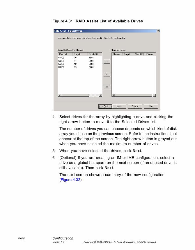
4-44 ConfigurationVersion 3.1 Copyright © 2001�2006 by LSI Logic Corporation. All rights reserved.
Figure 4.31 RAID Assist List of Available Drives
4. Select drives for the array by highlighting a drive and clicking the right arrow button to move it to the Selected Drives list.
The number of drives you can choose depends on which kind of disk array you chose on the previous screen. Refer to the instructions that appear at the top of the screen. The right arrow button is grayed out when you have selected the maximum number of drives.
5. When you have selected the drives, click Next.
6. (Optional) If you are creating an IM or IME configuration, select a drive as a global hot spare on the next screen (if an unused drive is still available). Then click Next.
The next screen shows a summary of the new configuration (Figure 4.32).
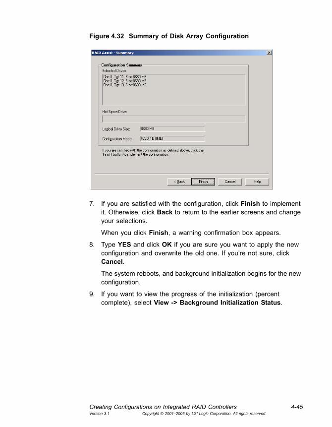
Creating Configurations on Integrated RAID Controllers 4-45Version 3.1 Copyright © 2001�2006 by LSI Logic Corporation. All rights reserved.
Figure 4.32 Summary of Disk Array Configuration
7. If you are satisfied with the configuration, click Finish to implement it. Otherwise, click Back to return to the earlier screens and change your selections.
When you click Finish, a warning confirmation box appears.
8. Type YES and click OK if you are sure you want to apply the new configuration and overwrite the old one. If you�re not sure, click Cancel.
The system reboots, and background initialization begins for the new configuration.
9. If you want to view the progress of the initialization (percent complete), select View -> Background Initialization Status.

4-46 ConfigurationVersion 3.1 Copyright © 2001�2006 by LSI Logic Corporation. All rights reserved.
Global Array Manager Transition Tool Client Software User�s Guide 5-1Version 3.1 Copyright © 2001�2006 by LSI Logic Corporation. All rights reserved.
Chapter 5Monitoring Events, Devices, and Processes
You can use Global Array Management Client to monitor the status of system events, storage devices, and system processes such as disk rebuilds. This chapter has the following sections:
• Section 5.1, �Monitoring Events�
• Section 5.2, �Monitoring Controllers�
• Section 5.3, �Monitoring Physical Devices and Logical Drives�
• Section 5.4, �Monitoring Enclosures�
• Section 5.5, �Monitoring the Status of Processes�
• Section 5.6, �Monitoring and Maintaining Battery Backup Units�
Monitoring the status of an Intelligent Battery Backup Unit (BBU), and recharging/reconditioning the battery, if needed.
5.1 Monitoring Events
GAMTT Server software monitors the activity and performance of disk drives, controllers, and other storage devices. When an activity results in an �event�, the event is sent to workstations that are running GAMTT Client. There are various categories of events ranging from �serious� events such as a disk failure to �informational� events such as the completion of a consistency check. For descriptions of all events, see Appendix A, �Event and Message Information.�
Events are displayed in the Log Information Viewer, which is described in Section 3.2.1.2, �Log Information Viewer.�
LSI Logic recommends that you leave the GAMTT Client running as long as there are servers you want to monitor. If you exit, you cannot receive

5-2 Monitoring Events, Devices, and ProcessesVersion 3.1 Copyright © 2001�2006 by LSI Logic Corporation. All rights reserved.
event information from GAMTT Server unless you restart GAMTT Client and reconnect to the server(s).
5.1.1 Opening the Log Information Viewer
The Log Information Viewer opens when you start GAMTT and it detects one or more controllers (see Section 3.2.1.2, �Log Information Viewer,� page 3-4). The viewer displays a chronological log of all the events that occur during this session of the program. By default, the log file is named gam2cl.log. The log file name and location can be changed on the Alert Preferences page or in the gam2cl.ini file.
5.1.2 Opening an Event Information Window
You can open an Event Information Window to view more information about any event displayed in the Log Information Viewer. Appendix A lists all event descriptions, causes, and actions.
To open the event information window for a particular event, double-click the event entry in the Log Information Viewer. An event information window for your selected event is displayed. Figure 5.1 shows an example:
Figure 5.1 Event Information Window

Monitoring Controllers 5-3Version 3.1 Copyright © 2001�2006 by LSI Logic Corporation. All rights reserved.
The Event ID and Severity Level appear in the window�s title bar. The most useful fields in the Event Information window are:
• CAUSE. Possible reasons that the event occurred, and
• REQUIRED ACTION. What you should do in response to this message. Informational messages usually have no required actions. Critical, Serious, Error, and Warning messages may specify useful required actions.
Click OK to close the event information window.
5.2 Monitoring Controllers
After a client and server connection is made through sign-on, the GAMTT Client opens a Controller View window for each RAID controller and the drives connected to it. (See Section 3.2.2, �Controller View Window,� page 3-5 for a detailed description.)
5.2.1 Displaying Controller Information
To display controller Information, select Administration->Controller
Information, or click the Controller Information icon .
Figure 5.2 shows the Controller Information window for a PCI RAID controller.

5-4 Monitoring Events, Devices, and ProcessesVersion 3.1 Copyright © 2001�2006 by LSI Logic Corporation. All rights reserved.
Figure 5.2 Controller Information
Most of this information is self-explanatory. Note the following:
• �Intelligent BBU� indicates whether an Intelligent Battery Backup Unit is installed (�N/A� means the controller does not support a BBU.)
• The IRQ entry for MegaRAID and SAS controllers always displays N/A.
• For SAS controllers, the Host Information is Bus #, Device #, and IRQ.
Click Controller Options to view a dialog box that lists user-adjustable controller parameters (see Section 4.2, �Setting and Changing Controller Options,� page 4-3). Click Close to close the Controller Information window.
Note: On Ultra320 SCSI controllers that support IM and IME arrays, you can only view the controller information.

Monitoring Physical Devices and Logical Drives 5-5Version 3.1 Copyright © 2001�2006 by LSI Logic Corporation. All rights reserved.
5.3 Monitoring Physical Devices and Logical Drives
This section describes how the GAMTT Client monitors physical devices and logical drives.
5.3.1 Displaying Device Information
The Controller View window shows which physical devices are associated with each controller channel. Each stack of drives represents the physical drives connected to a single channel on the controller.
A physical device can be a host controller, a CD-ROM drive, disk drive, tape drive, etc. Double-click a physical device icon to display information about the physical device. Figure 5.3 shows information for a Mylex controller.
Figure 5.3 Host Device Information � Mylex Controller
Figure 5.4 shows information for a disk device (disk drive).

5-6 Monitoring Events, Devices, and ProcessesVersion 3.1 Copyright © 2001�2006 by LSI Logic Corporation. All rights reserved.
Figure 5.4 Disk Device Information
Most of this information is self-explanatory. Note the following:
• If the disk drive is in an enclosure, the Enclosure Number and Slot Number fields appear in the Device Inquiry Data panel of the screen.
• If the current Status of the disk is Failed, a failure indicator is listed (see Appendix A for a list of error codes).
• Soft error and parity error information is not available for MegaRAID or SAS controllers.
• You can click Reset Errors to return all error tallies to 0.
• If the current status of the disk is Dead, a failure indicator display appears in the Device State area of the screen.
Note: For IM and IME configurations on Ultra320 SCSI controllers, only the Locate and Close buttons are supported.
If the disk drive�s status is Rebuild, the Rebuild button may be available so that you can start a physical device rebuild.
If the physical device is unconfigured, the Make Ready button may be available to make this disk device available for configuration. After you
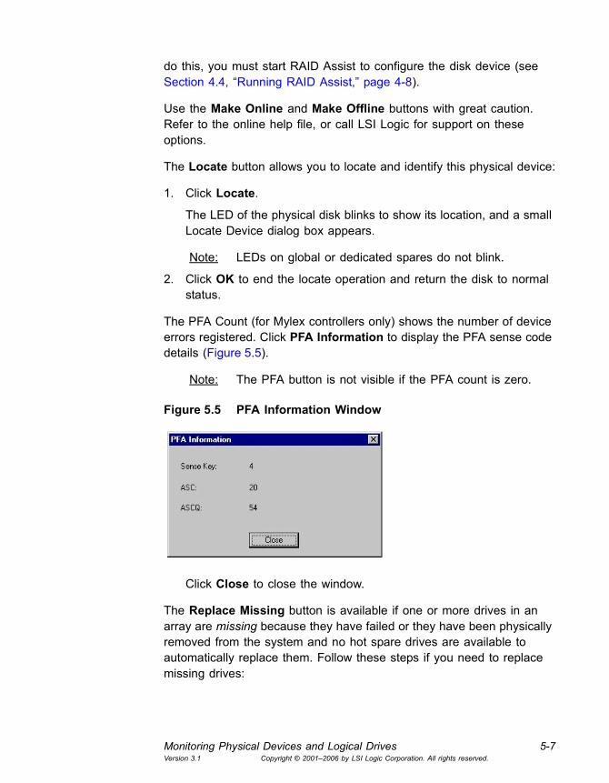
Monitoring Physical Devices and Logical Drives 5-7Version 3.1 Copyright © 2001�2006 by LSI Logic Corporation. All rights reserved.
do this, you must start RAID Assist to configure the disk device (see Section 4.4, �Running RAID Assist,� page 4-8).
Use the Make Online and Make Offline buttons with great caution. Refer to the online help file, or call LSI Logic for support on these options.
The Locate button allows you to locate and identify this physical device:
1. Click Locate.
The LED of the physical disk blinks to show its location, and a small Locate Device dialog box appears.
Note: LEDs on global or dedicated spares do not blink.
2. Click OK to end the locate operation and return the disk to normal status.
The PFA Count (for Mylex controllers only) shows the number of device errors registered. Click PFA Information to display the PFA sense code details (Figure 5.5).
Note: The PFA button is not visible if the PFA count is zero.
Figure 5.5 PFA Information Window
Click Close to close the window.
The Replace Missing button is available if one or more drives in an array are missing because they have failed or they have been physically removed from the system and no hot spare drives are available to automatically replace them. Follow these steps if you need to replace missing drives:
5-8 Monitoring Events, Devices, and ProcessesVersion 3.1 Copyright © 2001�2006 by LSI Logic Corporation. All rights reserved.
1. If necessary, physically replace the failed or missing disk drive in your system.
Caution: If you are replacing multiple failed drives in an array, you must replace them in the correct sequence to avoid losing or corrupting data. For example, consider a three-drive RAID 5 array in which two drives have failed. When the first drive fails, the array becomes critical (degraded), but you can still write data to and read data from the array. When the second drive fails, the array goes offline, and data written to the second failed drive is not on the first failed drive. So you must replace the second failed drive first and only then replace the first failed drive, in order to avoid corrupted data.
2. Click the icon of the replacement drive in the Controller View window (see Section 3.2.2, �Controller View Window�).
3. In the Disk Device Information window, click Replace Missing.
A small dialog box appears listing the Array Reference (the number of the array with the missing disk drive) and the Row Number of the disk drive you have selected as a replacement.
4. Change the Array Reference and Row Number information, if necessary, and click OK to accept the information.
5. Wait until the replacement disk drive is added to the array.
5.3.2 Viewing the IR Error Log (Integrated RAID Configurations Only)
To open the Error Table for Integrated RAID configurations on Ultra320 SCSI controllers or SAS controllers, select View -> Error Table on the
menu bar, or click the Error Table icon . The IR Error Log appears, as shown in Figure 5.6.

Monitoring Physical Devices and Logical Drives 5-9Version 3.1 Copyright © 2001�2006 by LSI Logic Corporation. All rights reserved.
Figure 5.6 Integrated Raid (IR) Error Log
This information may be useful for troubleshooting. GAM checks for device errors at every polling period (the default polling period is 1 minute). If it detects multiple errors, only the last error is displayed in the error log. The Number of Errors field at the bottom of the screen, however, lists the total number of errors that GAM has detected during the current session. So, for example, after the first polling period you might see one error line in the log and 15 in the Number of Errors field.
You must click Refresh to update the log display while the window is open. The log entries shown on this screen are deleted at the end of each GAM session. If you want to save the information, click Save File and enter a name and a location for the file.
Note: You can change the polling period by setting the option in the configuration file. The allowable range is 1�60 minutes.
5.3.3 Viewing the Request Sense Data and NVRAM Error Log
This section describes the Error Table information for all supported controllers except for Ultra320 controllers with IM or IME configurations, To view the Error Table, select View -> Error Table on the menu bar, or
click the Error Table icon .

5-10 Monitoring Events, Devices, and ProcessesVersion 3.1 Copyright © 2001�2006 by LSI Logic Corporation. All rights reserved.
The Error Table has two tabs. The Request Sense Data tab displays the type of information shown in Figure 5.7:
Figure 5.7 Request Sense Data
This information may be useful for troubleshooting.
• Click Save File to record the request sense data in an .rsd file for later use. (The log entries shown on this screen are deleted at the end of each GAM session.)
• Click Read File to open and view an .rsd file that was previously saved.
• Click Close to close the Error Table.
For Mylex controllers, SAS controllers, and some kinds of MegaRAID controllers, a tab for NVRAM Error Log is also available (Figure 5.8):
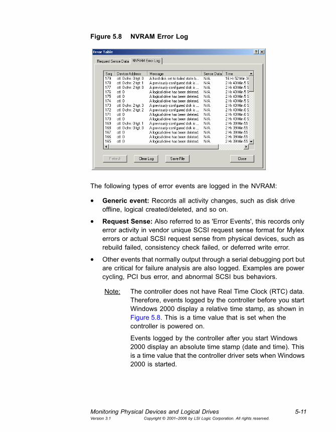
Monitoring Physical Devices and Logical Drives 5-11Version 3.1 Copyright © 2001�2006 by LSI Logic Corporation. All rights reserved.
Figure 5.8 NVRAM Error Log
The following types of error events are logged in the NVRAM:
• Generic event: Records all activity changes, such as disk drive offline, logical created/deleted, and so on.
• Request Sense: Also referred to as 'Error Events', this records only error activity in vendor unique SCSI request sense format for Mylex errors or actual SCSI request sense from physical devices, such as rebuild failed, consistency check failed, or deferred write error.
• Other events that normally output through a serial debugging port but are critical for failure analysis are also logged. Examples are power cycling, PCI bus error, and abnormal SCSI bus behaviors.
Note: The controller does not have Real Time Clock (RTC) data. Therefore, events logged by the controller before you start Windows 2000 display a relative time stamp, as shown in Figure 5.8. This is a time value that is set when the controller is powered on.
Events logged by the controller after you start Windows 2000 display an absolute time stamp (date and time). This is a time value that the controller driver sets when Windows 2000 is started.
5-12 Monitoring Events, Devices, and ProcessesVersion 3.1 Copyright © 2001�2006 by LSI Logic Corporation. All rights reserved.
• The time information is displayed differently for MegaRAID/SAS and Mylex controllers.
� MegaRAID and SAS controllers display date and time as m/d/h:m:ss/yyyy.
� Mylex controllers display date and time as #h;#m:#ss since system started.
The following describes the button functions for the NVRAM Error Log:
• To save the NVRAM Error data for failure analysis and troubleshooting, click Save File. (The log entries shown on this screen are deleted at the end of each GAM session.)
• To clear the NVRAM Error Log, click Clear Log.
• To update the NVRAM Error Log with the latest errors from the controller, click Refresh.
• Click Close to close the Error Table.

Monitoring Physical Devices and Logical Drives 5-13Version 3.1 Copyright © 2001�2006 by LSI Logic Corporation. All rights reserved.
5.3.4 Displaying Logical Drive Information
The icons on the right side of the Controller View window represent the logical drives on the controller. Double-click a logical drive icon to display information about the logical drive (Figure 5.9).
Figure 5.9 Logical Drive Information
Note: Only the Locate and Close buttons are supported for logical drives on Ultra320 SCSI controllers that support IM and IME configurations.
Most of the logical drive information is self explanatory. Note the following:
• If the write back cache is disabled, click Enable Write Cache to enable it.
MegaRAID/SAS controllers
Mylexcontrollers
5-14 Monitoring Events, Devices, and ProcessesVersion 3.1 Copyright © 2001�2006 by LSI Logic Corporation. All rights reserved.
• If the write back cache is enabled, click Disable Write Cache to disable it (and use write through caching).
• If the Consistency Check button is enabled, you may manually run a consistency check on this logical drive (as discussed in the next chapter).
Note: When you are running GAMTT Client with a SAS controller, this button is labeled Make Data Consistent.
• Click Show Bad Data Blocks to display a window of all bad data blocks found on this logical drive.
• (Mylex controllers only) If the logical drive is offline due to some external cause such as a power failure, click Force On Line to return it to an active state. A warning window appears asking for confirmation of this command.
Caution: Use the Force On Line command only to recover from a power failure. Doing so at any other time could result in data loss.
The Locate button allows you to locate the physical devices that comprise this logical drive.
1. Click Locate.
The LEDs of the physical disks blink to show their location, and a small Locate Device dialog box appears.
Note: LEDs on global or dedicated spares do not blink.
2. Click OK to end the locate operation and return the disks to normal status.
The Transport button (Mylex controllers only) opens the Disk Array Transport Information window that shows all of the physical drives, including the spares associated with the selected logical drive, and all of the logical drives that belong to the same disk array. See Section 4.10, �Transporting a Disk Array (Mylex Controllers Only),� page 4-33 for details.

Monitoring Enclosures 5-15Version 3.1 Copyright © 2001�2006 by LSI Logic Corporation. All rights reserved.
5.4 Monitoring Enclosures
The Controller View window has an Enclosure button with a status light. A green square indicates OK, a yellow circle indicates Critical status, and a red X indicates failed status. You can monitor enclosure information and status by clicking the Enclosure button or by selecting Administration -> Enclosure Information.
The Enclosure Information dialog box is displayed with the Information page active (Figure 5.10).
Figure 5.10 Enclosure Information Page
5.4.1 Information Page
Enclosure Information displays the following information:
• The status of each enclosure, identified by an icon and an enclosure number (1�32)1, and a status:
� OK � All components are optimal.
� Critical � Some component has failed; one more failure may result in data loss.
� Failed � A failure has occurred that may result in data loss.
1. An undetermined enclosure shows as a zero (0). In this case, all information is presented as if there is a single enclosure with all the fans, power supplies, etc.
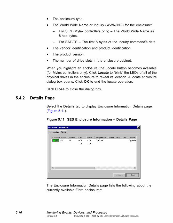
5-16 Monitoring Events, Devices, and ProcessesVersion 3.1 Copyright © 2001�2006 by LSI Logic Corporation. All rights reserved.
• The enclosure type.
• The World Wide Name or Inquiry (WWN/INQ) for the enclosure:
� For SES (Mylex controllers only) � The World Wide Name as 8 hex bytes.
� For SAF-TE � The first 8 bytes of the Inquiry command�s data.
• The vendor identification and product identification.
• The product version.
• The number of drive slots in the enclosure cabinet.
When you highlight an enclosure, the Locate button becomes available (for Mylex controllers only). Click Locate to �blink� the LEDs of all of the physical drives in the enclosure to reveal its location. A locate enclosure dialog box opens. Click OK to end the locate operation.
Click Close to close the dialog box.
5.4.2 Details Page
Select the Details tab to display Enclosure Information Details page (Figure 5.11).
Figure 5.11 SES Enclosure Information � Details Page
The Enclosure Information Details page lists the following about the currently-available Fibre enclosures:

Monitoring Enclosures 5-17Version 3.1 Copyright © 2001�2006 by LSI Logic Corporation. All rights reserved.
• The status of each enclosure, identified by an icon and an enclosure number, and a status:
� OK � All components are optimal.
� Critical � Some component has failed; one more failure may result in data loss.
� Failed � A failure has occurred that may result in data loss.
• The access status of each enclosure indicates the controller�s ability to communicate with the enclosure. The status values are:
� OK � Access is optimal.
� Critical � Only one access path remains of the several that were detected previously. If the last access path is lost, the controller will take steps to protect the data.
� Lost � The controller cannot communicate with the enclosure. The controller will not sense any failures in the enclosure while this state exists.
• The status of the fans in the enclosure. Each fan is designated with a number and a status:
� Absent � The fan is not installed, or has failed in an undetectable way.
� OK � The fan is optimal. Fan speed is shown as either Stopped, Low, or High. (Speed is not shown for SAF-TE enclosures.)
� Failed � The fan is installed, but has failed.
• The status of the power supplies in the enclosure. Each power supply is designated with a number and a status:
� Absent � The power supply is not installed, or has failed in an undetectable way.
� OK � The power supply is optimal.
� Failed � The power supply is installed, but has failed.
• The status of the temperature sensors in the enclosure. Each temperature sensor is designated with a number and a status:
� Absent � The temperature sensor is not installed, or has failed in an undetectable way.
� OK � The temperature sensor is optimal. Two additional items are displayed with this state: Celsius Temperature (range for

5-18 Monitoring Events, Devices, and ProcessesVersion 3.1 Copyright © 2001�2006 by LSI Logic Corporation. All rights reserved.
SES is −19º to +235º; range for SAF-TE is -10º to +245º); Over Temperature Warning (OT).
� Failed � The temperature sensor is installed, but has failed.
• The status of the alarms in the enclosure. Each alarm is designated with a number and a status:
� Absent � The alarm is not installed, or has failed in an undetectable way.
� OK � The alarm is optimal. One additional item is displayed with this state: ON � the alarm is currently on or sounding.
� Failed � The alarm is installed, but has failed.
• The status of the enclosure�s connection to one or more Uninterruptible Power Supplies (UPS). Each UPS is assigned a number and a status:
� Absent � The UPS is not installed, or has failed in an undetectable way.
� OK � The UPS is optimal. Three additional items are displayed with this state: AC Pwr � the UPS is reporting an AC power failure; DC Pwr � the UPS is reporting a DC power failure; Low Bat � the UPS can power the system for only 2 to 5 more minutes.
� Failed � The UPS is installed, but has failed.
• Error status for troubleshooting purposes. Error status for an enclosure is reported in a format similar to the following example:
0 Addressing 25 02:03 04:05
� 0 is the error number.
� Addressing is the error type.
� 25 is the ALPA (Arbitrated Loop/Port Address) of the drive in question.
� 02:03 is the first known channel and target to which the ALPA is mapped.
� 04:05 is the second known channel and target to which the ALPA is mapped.
An Information field contains most of the items listed on the Information page for easier cross-reference.

Monitoring Enclosures 5-19Version 3.1 Copyright © 2001�2006 by LSI Logic Corporation. All rights reserved.
The Locate button becomes available when you highlight an enclosure. Click this button to blink the LEDs of all of the physical drives in the enclosure. A Locate Enclosure dialog box opens.
Click Close to close the dialog box.
5.4.3 Enclosures Devices
Among the stack of drive icons displayed in a channel tower of the Controller View window, you will find an enclosure device icon, which looks like this:
Double-click the enclosure device icon to display information about the enclosure device (Figure 5.12).
Figure 5.12 Enclosure Device Information
The Enclosure Device Information dialog box displays the following about the currently-selected enclosure device:
• Device Inquiry Data information, such as vendor, product, product revision, bus width, etc.
• Device State information: transfer speed and bus width
• Enclosure information: enclosure ID and enclosure index
Click Close to close the dialog box.

5-20 Monitoring Events, Devices, and ProcessesVersion 3.1 Copyright © 2001�2006 by LSI Logic Corporation. All rights reserved.
5.5 Monitoring the Status of Processes
This section describes how to monitor long operation tasks, such as initialization and rebuild.
5.5.1 Background and Foreground Initialization Status
While a background or foreground initialization is running, open the Background/Foreground Initialize Status box by selecting View -> Foreground [Background] Initialize Status to monitor the process.
Figure 5.13 Foreground Initialization Status Box Shown
The Initialize Status box (Figure 5.13) displays the progress of one or more full logical drive initializations.
To cancel ALL Foreground drive initializations at the same time...
Click Select All, which selects all drives for cancellation, then click Cancel to stop all the initializations.
To cancel individual drive initializations...
Check the box(es) of the drive(s) to cancel, then click Cancel to stop only those initializations (does not apply to IME arrays on Ultra320 SCSI controllers).
To deselect drives that you selected for cancellation...
Click Clear All, which deselects all drives for cancellation, then click Close to close the Initialize Status box.
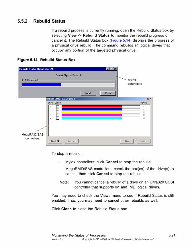
Monitoring the Status of Processes 5-21Version 3.1 Copyright © 2001�2006 by LSI Logic Corporation. All rights reserved.
5.5.2 Rebuild Status
If a rebuild process is currently running, open the Rebuild Status box by selecting View -> Rebuild Status to monitor the rebuild progress or cancel it. The Rebuild Status box (Figure 5.14) displays the progress of a physical drive rebuild. The command rebuilds all logical drives that occupy any portion of the targeted physical drive.
Figure 5.14 Rebuild Status Box
To stop a rebuild:
� Mylex controllers: click Cancel to stop the rebuild.
� MegaRAID/SAS controllers: check the box(es) of the drive(s) to cancel, then click Cancel to stop the rebuild.
Note: You cannot cancel a rebuild of a drive on an Ultra320 SCSI controller that supports IM and IME logical drives.
You may need to check the Views menu to see if Rebuild Status is still enabled. If so, you may need to cancel other rebuilds as well.
Click Close to close the Rebuild Status box.
Mylexcontrollers
MegaRAID/SAS controllers

5-22 Monitoring Events, Devices, and ProcessesVersion 3.1 Copyright © 2001�2006 by LSI Logic Corporation. All rights reserved.
5.5.3 Consistency Check Status
If a consistency check process is currently running, open the Consistency Check Status box by selecting View -> Consistency Check Status to monitor the consistency check progress or to cancel it. (For SAS controllers, this option is View -> Make Data Consistent.)
The Consistency Check Status box (Figure 5.15) displays the progress of a logical drive consistency check.
Figure 5.15 Consistency Check Status Box
To stop a consistency check:
� Mylex controllers: Click Cancel to stop the consistency check.
� MegaRAID/SAS controllers: Check the box(es) of the drive(s) to cancel, then click Cancel to stop the consistency check.
You may need to check the Views menu to see if Consistency Check Status is still enabled. If so, you may need to cancel other consistency checks as well.
Click Close to close the Consistency Check Status box.
Mylexcontrollers
MegaRAID/SAS controllers
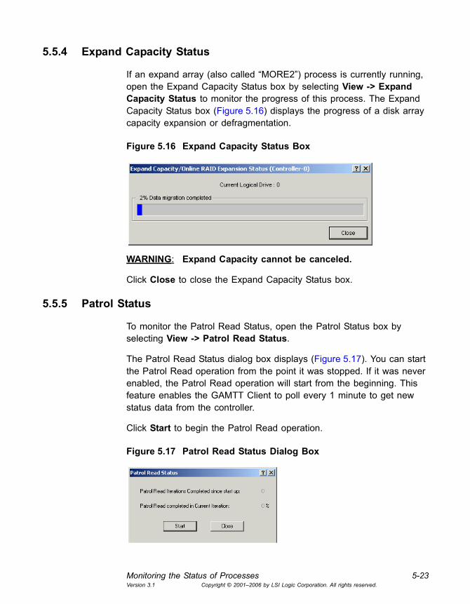
Monitoring the Status of Processes 5-23Version 3.1 Copyright © 2001�2006 by LSI Logic Corporation. All rights reserved.
5.5.4 Expand Capacity Status
If an expand array (also called �MORE2�) process is currently running, open the Expand Capacity Status box by selecting View -> Expand Capacity Status to monitor the progress of this process. The Expand Capacity Status box (Figure 5.16) displays the progress of a disk array capacity expansion or defragmentation.
Figure 5.16 Expand Capacity Status Box
WARNING: Expand Capacity cannot be canceled.
Click Close to close the Expand Capacity Status box.
5.5.5 Patrol Status
To monitor the Patrol Read Status, open the Patrol Status box by selecting View -> Patrol Read Status.
The Patrol Read Status dialog box displays (Figure 5.17). You can start the Patrol Read operation from the point it was stopped. If it was never enabled, the Patrol Read operation will start from the beginning. This feature enables the GAMTT Client to poll every 1 minute to get new status data from the controller.
Click Start to begin the Patrol Read operation.
Figure 5.17 Patrol Read Status Dialog Box

5-24 Monitoring Events, Devices, and ProcessesVersion 3.1 Copyright © 2001�2006 by LSI Logic Corporation. All rights reserved.
5.6 Monitoring and Maintaining Battery Backup Units
The following types of controllers support an Intelligent Battery Backup Unit (Intelligent BBU), which saves the controller�s data in RAM if there is an AC power failure to the disk storage system:
• New Mylex PCI RAID controllers
• MegaRAID Ultra320-2E controller
• SAS controllers
To open the Intelligent BBU dialog box, select Administration -> Intelligent BBU.
You use the Intelligent BBU dialog box to monitor, charge, and recharge the backup battery unit on the controller. The dialog box alerts you when a new battery pack is needed by indicating that the old pack can no longer hold a charge. You also use this dialog box to fully discharge and then charge a newly installed battery pack.
The following sections explain the information and options that are available on this dialog box.
5.6.1 Intelligent BBU for Mylex PCI RAID Controllers
Figure 5.18 shows the Intelligent BBU dialog box for Mylex PCI RAID controllers:
Figure 5.18 Intelligent BBU Dialog Box: Mylex PCI RAID Controllers
Monitoring and Maintaining Battery Backup Units 5-25Version 3.1 Copyright © 2001�2006 by LSI Logic Corporation. All rights reserved.
This dialog box lists the following information about the BBU.
5.6.1.1 Power Levels
The Power Levels area displays the battery unit�s current and maximum power levels, expressed in hours or minutes (selectable above the Refresh button). The charge level is also shown as a percentage of the maximum power level for the battery unit. (The Maximum Power level gradually decreases over the lifetime of the battery pack.) An alarm is triggered when the power level drops below the user-selectable Low Power Threshold. Follow these steps to change this threshold:
1. Enter the number of minutes or hours you want in the Low Power Threshold field.
2. Select Set Low Power Threshold in the Actions area of the dialog box.
3. Click the Apply button.
You can click Refresh to update the information shown in the dialog box. This is useful for monitoring the progress of a lengthy operation such as a Recondition without closing and reopening the dialog box.
5.6.1.2 Battery Status
The Battery Status area lists the battery type and the version number of the controller. The read-only check boxes indicate the following, when checked:
• Low Power Alarm. The battery unit�s Current Power value has dropped below the Low Power Threshold value.
• Never Reconditioned. This is checked for a new battery until it has been fully discharged and then charged using the Recondition Battery selection under Actions.
Note: LSI Logic recommends that you condition a new battery pack for maximum longevity before you use it.
• Reconditioning Needed. The battery has not been reconditioned within 30 discharge/charge cycles. Select Recondition Battery under Actions, then click Apply.

5-26 Monitoring Events, Devices, and ProcessesVersion 3.1 Copyright © 2001�2006 by LSI Logic Corporation. All rights reserved.
• Reconditioning Active. The battery is currently being discharged and recharged. To interrupt reconditioning (not recommended), select Stop Recondition under Actions, then click Apply.
• Fast Charging Active. The battery is being charged. A fast charge also occurs when the controller is powered on.
• Discharging Active. The battery is currently being discharged, which is the first stage of a Recondition Battery action.
5.6.1.3 Actions
The Actions area lists various battery pack commands that you can use as needed. The Actions are explained in the previous two sections. To perform an action, select it and then click Apply.
5.6.2 Intelligent BBU for MegaRAID Ultra320-2E and SAS Controllers
Figure 5.19 shows the Intelligent BBU dialog box for SAS controllers and the MegaRAID Ultra320-2E controller:
Figure 5.19 Intelligent BBU Dialog Box: SAS and MegaRAID Ultra320-E Controllers
This dialog box lists the following information about the BBU.
Monitoring and Maintaining Battery Backup Units 5-27Version 3.1 Copyright © 2001�2006 by LSI Logic Corporation. All rights reserved.
5.6.2.1 Battery Information
The Battery Information area of the dialog box lists the battery type, battery manufacturer, etc.
5.6.2.2 Battery Monitored Information
The Battery Monitored Information area of the dialog box lists the battery�s remaining capacity, temperature, voltage, and current. The Cycle Count field indicates how many times the battery has been recharged. When the battery is being charged, the Time to Full field indicates the time remaining before the battery will be fully discharged.
5.6.2.3 Battery Status
The Battery Status area of the dialog box lists the battery�s current status, which in this example is Fully Charged. The read-only Recalibration Needed box is checked if the battery needs to be recalibrated. To do this, click the Recalibrate button. The Recalibration Active box remains checked during the recalibration process.
Auto Learn Mode refers to the process of taking a fully charged battery through a discharge/charge cycle to update the capacity parameters. The default time for this process is 30 days. The options for Auto Learn Mode are as follows:
• Auto: (recommended) The discharge/charge cycle is performed automatically.
• Disable: Auto Learn Mode is disabled.
• Warn: A warning appears when the recalibration is needed, and the user must issue a Recalibrate command manually.
Click the Refresh button to update the information shown in the dialog box. This is useful for monitoring the progress of a battery-related operation without closing and reopening the dialog box.

5-28 Monitoring Events, Devices, and ProcessesVersion 3.1 Copyright © 2001�2006 by LSI Logic Corporation. All rights reserved.

Global Array Manager Transition Tool Client Software User�s Guide 6-1Version 3.1 Copyright © 2001�2006 by LSI Logic Corporation. All rights reserved.
Chapter 6Maintaining Storage Configurations
You can Global Array Management Client to perform maintenance activities on storage configurations. These activities include running consistency checks, rebuilding data on replacement disk drives, and upgrading controller firmware. This chapter contains the following sections:
• Section 6.1, �Initializing a Logical Drive�
• Section 6.2, �Running a Logical Drive Consistency Check�
• Section 6.3, �Running a Device Rebuild�
• Section 6.4, �Using the Flash Utility�
• Section 6.5, �Defragmenting an Array (Mylex Controllers Only)�
• Section 6.6, �Clearing a Configuration�
6.1 Initializing a Logical Drive
If it is not convenient to initialize a logical drive immediately following a configuration, you can use the Initialize Logical Drives option to initialize the logical drive at a later time.
Note: You cannot delay the initialization of a logical drive configured on an IM or IME array. The initialization begins automatically as soon as the configuration is complete.
To initialize a logical drive, follow these steps:
1. Select Administration->Initialize Logical Drives on the menu bar.
The Initialize Logical Drives dialog box opens (Figure 6.1).

6-2 Maintaining Storage ConfigurationsVersion 3.1 Copyright © 2001�2006 by LSI Logic Corporation. All rights reserved.
Figure 6.1 Initialize Logical Drives Dialog Box
2. Select the checkboxes next to the logical drive(s) you want to initialize.
3. Click OK to begin the initialization.
A Warning message dialog box appears for confirmation.
4. Type YES to confirm the initialization and click OK.
The Initialize Status Dialog box opens. See Section 5.5, �Monitoring the Status of Processes,� page 5-20 for more information.
6.2 Running a Logical Drive Consistency Check
You should periodically run a consistency check on fault tolerant logical drives to determine whether consistency data has become corrupted and needs to be restored. It is especially important to do this if you suspect that the logical drive consistency data may be corrupted.
Note: Ultra320 SCSI controllers with IM or IME configurations do not support this option.
To run a logical drive consistency check, follow these steps:
1. Open the Controller View window by double-clicking any server icon in the Global Status View, or by selecting View -> Controller View...
2. Double-click a logical drive from the list on the right side of the Controller View window.
Running a Device Rebuild 6-3Version 3.1 Copyright © 2001�2006 by LSI Logic Corporation. All rights reserved.
3. Click Consistency Check in the Logical Drive Information dialog box to begin. (For SAS controllers, this button is labeled Make Data Consistent.)
� For Mylex controllers: A message is displayed asking if you would like consistency to be restored in the event of errors.
� For MegaRAID and SAS controllers: Consistency Check Restoration occurs if the parameter is set to Enable. (See Section 3.4.3, �Administration Menu,� page 3-11, for a description of this parameter.)
4. Click Yes to restore consistency during the process, or click No if you just want to carry out the consistency check.
Note: SAS controllers do not support consistency check with restoration.
Caution: Use the Yes option with caution! If the consistency data on a logical drive is badly corrupted, the real data may become corrupted if you attempt to restore consistency.
There is no risk of data loss if you select No. Errors are still reported to the Error Table, but no attempt is made to correct them.
5. When the Consistency Check Status box appears, you can either close it or leave it open until the consistency check has completed. (See Section 5.5.3, �Consistency Check Status,� page 5-22.)
You can run multiple consistency checks with MegaRAID and SAS controllers.
6.3 Running a Device Rebuild
If a single drive in a fault tolerant system fails, the system is protected from data loss by the striping with parity data across the logical drive (RAID 3, RAID 5) or by the total redundancy of data (RAID 1, RAID 10). The failed drive must be replaced, and the failed drive�s data must be rebuilt on a new drive to restore the system to fault tolerance.
The device rebuild function performs this task. A failed drive�s data can be rebuilt to:
• The original drive, if this drive is still functional

6-4 Maintaining Storage ConfigurationsVersion 3.1 Copyright © 2001�2006 by LSI Logic Corporation. All rights reserved.
• A hot spare drive
• A new drive inserted in place of the failed drive
Note: The device rebuild function for Ultra320 SCSI controllers with IM or IME configurations is automatic: you do not need to �run� a rebuild, and there is no Rebuild button on the Disk Device Information screen.
To rebuild a failed drive, follow these steps:
1. Remove and reinsert the drive that caused the failure (if it is still a good drive), or replace the failed drive with a new drive of equal or greater capacity.
2. Double-click the relevant physical device icon in the Controller View window.
The Disk Device Information dialog box opens, and the Rebuild button should be available (Figure 6.2).
Figure 6.2 Rebuild Button Available for This Disk Device
3. Click Rebuild.
Rebuild runs and the Rebuild Status window appears.
4. Close the Rebuild Status box and continue, or leave the window open until the drive has been rebuilt.
With MegaRAID and SAS controllers you can run multiple rebuilds; however, only one rebuild per array can be performed.

Using the Flash Utility 6-5Version 3.1 Copyright © 2001�2006 by LSI Logic Corporation. All rights reserved.
When rebuild has completed, the selected physical device and the logical drive(s) of which it is a part are returned to operational status. If you cancel the rebuild, the device returns to its offline (dead) status (red X), and the logical drives that occupy this physical device all go to critical status (yellow exclamation point). You must complete a future rebuild to return the physical device and logical drive(s) to operational status.
6.4 Using the Flash Utility
Note: Ultra320 SCSI controllers with IM or IME configurations do not support the Flash Utility option.
The Flash Utility is used to upgrade firmware, BIOS, boot block, and BIOS Configuration Utility software by �flashing� the new code stored in an identified .IMG (Mylex) or .ROM (MegaRAID/SAS) firmware file to the controller�s on-board BIOS. This utility allows you to keep your controller current as maintenance releases of this code become available.
Caution: If Expand Array (Expand Capacity) is running or was stopped, you must allow the process to run to completion before replacing controllers and flashing new firmware. Otherwise, data may be corrupted!
Open the Flash Utility by selecting Administration -> Flash Utility. The Flash Utility dialog box appears, as shown in Figure 6.3:
Figure 6.3 Flash Utility Dialog Box
The Current RAM Information panel lists information about the code that is currently stored in the BIOS of the selected controller. This information

6-6 Maintaining Storage ConfigurationsVersion 3.1 Copyright © 2001�2006 by LSI Logic Corporation. All rights reserved.
is helpful for troubleshooting and for determining whether you need to upgrade the firmware, BIOS, and so on.
To perform a flash upgrade, follow these steps:
1. Type the name of the appropriate firmware file (.IMG or .ROM) in the Flash file selection box, or click Browse to locate the file.
If you select Browse, the Open Image file dialog box appears.
2. Select the firmware file in the Open Image file dialog box.
3. Click Open.
The Start Flash button becomes available in the Flash Utility dialog box, and the Flash file selection area displays information about the firmware file (Figure 6.4).

Using the Flash Utility 6-7Version 3.1 Copyright © 2001�2006 by LSI Logic Corporation. All rights reserved.
Figure 6.4 Additional Flash File Information
4. Compare the information for the new .IMG (Mylex) or .ROM (MegaRAID/SAS) file with the current information to confirm that a flash is needed. (For example, be sure that the .IMG or .ROM file contains a newer version of firmware code.)
5. Click Start Flash.
Because flashing new firmware code to the controller erases what was there previously, two levels of confirmation are required to proceed with the flash.
6. Click OK at the first confirmation message.
7. Type YES, then click OK at the second confirmation message.
The controller is updated with the new firmware code from the .IMG or .ROM file.
Mylexcontrollers
MegaRAID/SAS controllers

6-8 Maintaining Storage ConfigurationsVersion 3.1 Copyright © 2001�2006 by LSI Logic Corporation. All rights reserved.
6.5 Defragmenting an Array (Mylex Controllers Only)
When you randomly delete a logical drive(s), unused spaces are created in an array. Use the Defragment Array feature to unify the disk space.
To defragment an array, follow these steps:
1. Open RAID Assist by selecting Administration->RAID Assist or by
clicking the RAID assist icon .
2. Click Manual Configuration.
3. Click Defragment Array.
The Manual Configuration/Defragment Array window opens (Figure 6.5).
Figure 6.5 Manual Configuration/Defragment Array
This window displays all arrays under the selected controller. The array at the top of the list is selected by default. If the selected array has two or more unused spaces, the Apply button becomes enabled.
The Logical Drives panel on the right side of the window shows the RAID level and size of the logical drives in the selected array.
The Array Space panel shows the following information:
� Total unused disk space (Mbytes)
� Number of unused spaces in the array
� Size of the largest unused space (Mbytes) in the array
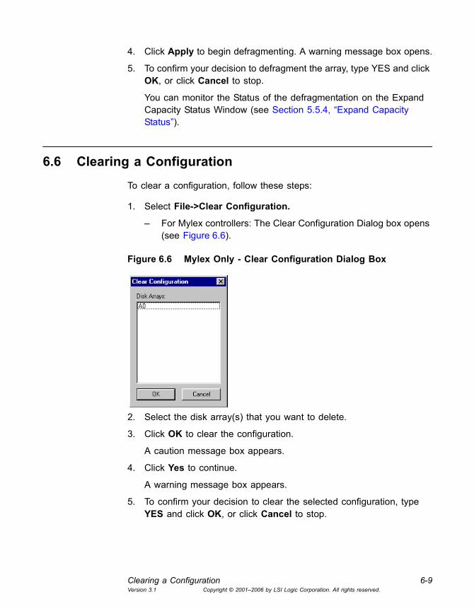
Clearing a Configuration 6-9Version 3.1 Copyright © 2001�2006 by LSI Logic Corporation. All rights reserved.
4. Click Apply to begin defragmenting. A warning message box opens.
5. To confirm your decision to defragment the array, type YES and click OK, or click Cancel to stop.
You can monitor the Status of the defragmentation on the Expand Capacity Status Window (see Section 5.5.4, �Expand Capacity Status�).
6.6 Clearing a Configuration
To clear a configuration, follow these steps:
1. Select File->Clear Configuration.
� For Mylex controllers: The Clear Configuration Dialog box opens (see Figure 6.6).
Figure 6.6 Mylex Only - Clear Configuration Dialog Box
2. Select the disk array(s) that you want to delete.
3. Click OK to clear the configuration.
A caution message box appears.
4. Click Yes to continue.
A warning message box appears.
5. To confirm your decision to clear the selected configuration, type YES and click OK, or click Cancel to stop.

6-10 Maintaining Storage ConfigurationsVersion 3.1 Copyright © 2001�2006 by LSI Logic Corporation. All rights reserved.

Global Array Manager Transition Tool Client Software User�s Guide 7-1Version 3.1 Copyright © 2001�2006 by LSI Logic Corporation. All rights reserved.
Chapter 7Using GAMTT with Embedded MegaRAID Software
This chapter explains how to use Global Array Manager Transition Tool (GAMTT) Client software with Embedded MegaRAID Software. Embedded MegaRAID Software provides RAID functionality via drivers and firmware, instead of via an actual physical RAID controller.
The information is in this separate chapter for your convenience, because some GAMTT Client features work differently with Embedded MegaRAID Software than they do with SAS and SCSI RAID controllers. Also, some GAMTT screens and dialog boxes look different when you are running GAMTT with Embedded MegaRAID Software.
This chapter includes the following sections:
• Section 7.1, �Main GAMTT Client Windows,� page 7-2
• Section 7.2, �Device Icons, Toolbar Icons, and Menus,� page 7-6
• Section 7.3, �Configuration,� page 7-9
• Section 7.4, �Running RAID Assist,� page 7-11
• Section 7.5, �Adding a Logical Drive,� page 7-21
• Section 7.6, �Deleting a Logical Drive,� page 7-23
• Section 7.7, �Creating Hot Spares,� page 7-24
• Section 7.8, �Loading a Configuration from Disk,� page 7-24
• Section 7.9, �Saving a Configuration to Disk,� page 7-25
• Section 7.10, �Clearing a Configuration,� page 7-25
• Section 7.11, �Monitoring Activities,� page 7-25
• Section 7.12, �Maintenance Processes,� page 7-32

7-2 Using GAMTT with Embedded MegaRAID SoftwareVersion 3.1 Copyright © 2001�2006 by LSI Logic Corporation. All rights reserved.
Some GAMTT Client information is not repeated in this chapter because it is the same as the information presented in Chapters 1 through 3. This includes the following topics:
• Overview of GAMTT functions; Client hardware and software system requirements (see Chapter 1, �Introduction�)
• GAMTT Client software installation (see Chapter 2, �Installation�)
• Starting GAMTT Server and Client software (see Section 3.1, �Starting Global Array Manager Transition Tool (GAMTT)�)
• Setting up servers and server groups (see Section 3.5, �Setting Up Server Groups and Servers,� page 3-13)
• Signing on to a server (see Section 3.6, �Signing On to a Server,� page 3-14)
• Setting and modifying user preferences (see Section 3.7, �Setting and Modifying User Preferences,� page 3-16)
7.1 Main GAMTT Client Windows
This section describes the main GAMTT window that appears with Embedded MegaRAID Software when you start the program and the Controller View window, through which you can view controller and device information.
7.1.1 Global Array Manager Window
If at least one server group is defined, the Global Array Manager window, shown in Figure 7.1, appears when you start GAMTT Client software. Within the Global Array Manager window are the Global Status View window and the Log Information Viewer.

Main GAMTT Client Windows 7-3Version 3.1 Copyright © 2001�2006 by LSI Logic Corporation. All rights reserved.
Figure 7.1 Opening Global Array Manager Window
7.1.1.1 Components of the GAMTT Client Windows
The components of the Global Array Manager window, which are shown in Figure 7.1, are described below.
1. Menu bar: The menu options are described later in this chapter.
2. Toolbar: The toolbar icons are described in Section 7.2, �Device Icons, Toolbar Icons, and Menus,� page 7-6.
3. Server group selection box: When selected, the box displays the names of each server group that is in contact with the current client workstation. Each group may consist of multiple servers. You may select a specific server group to view, or select �All Servers� if you want to view all the servers that are connected to this workstation.
4. Controller selection box: When selected, the box displays the controller ID (C-0, C-1, etc.) and controller type (Embedded MegaRAID Software, etc.) of each controller connected to the currently-selected server.
#1 #2 #3 #4
#5 #6

7-4 Using GAMTT with Embedded MegaRAID SoftwareVersion 3.1 Copyright © 2001�2006 by LSI Logic Corporation. All rights reserved.
7.1.1.2 Components of the Global Status View Window
5. An icon that represents the currently-selected file server running the GAMTT Server component. The icon identifies:
� the IP address (e.g. 10.17.3.172) or name (for example, ide40) of the server
� the network operating system running on the server (2000 = Windows 2000; NW = Novell NetWare, and so on)
� the operational status of the server (green = functioning, yellow = attempting connection, red �X� = unable to connect)
� the number of controllers connected on the server, with a controller operational status light (green = functioning, yellow = critical, red �X� = down or nonfunctional)
7.1.1.3 Components of the Log Information Viewer
6. GAMTT Client Log Information Viewer: Each line in the Log Information Viewer identifies a single event (error, status, warning, etc.) that was noted during monitoring by a file server running GAMTT Server. The following information is listed for each event:
� Event ID. Displays an icon showing whether the event is informational, cautionary, a warning, etc., plus the identification number assigned to this event.
� Severity. The severity level of this event (see Table A.1).
� Source. The IP address or name of the file server that is the sender (source) of this event.
� Source Time. Date and time at the source file server�s location when this event occurred.
� Device Address. Relevant channel/target or other data pertaining to the source of this event.
� Description. Text of the message describing what occurred.
� Sequence (Seq). Number representing where this event fell in a stream of events from the same source.
� Local Time. Date and time at the local client workstation�s location when this event arrived.

Main GAMTT Client Windows 7-5Version 3.1 Copyright © 2001�2006 by LSI Logic Corporation. All rights reserved.
7.1.2 Controller View Window
To open the Controller View window, double-click any server icon in the Global Status View window, or select View -> Controller View...
Note: If you want the Controller View window to show real-time information, and if you don�t have a real IP address on the GAMTT server, you must set the GAMTT Server event notification destination address with the loop back IP address (127.0.0.1). See the Global Array Manager Transition Tool Server User�s Guide for instructions on how to update the server event file (gamscm.ini).
Figure 7.2 Controller View Window � �SATA� RAID Adapter
The Controller View window (Figure 7.2) displays the following information about the controller currently selected in the controller selection box:
1. The physical devices present on each port, specifying the target ID, capacity of the device, device type, and device status. Four SATA drives are connected to this controller.
2. The logical drives configured on the controller, specifying the logical drive number, capacity, RAID level, and status.
#1 #2

7-6 Using GAMTT with Embedded MegaRAID SoftwareVersion 3.1 Copyright © 2001�2006 by LSI Logic Corporation. All rights reserved.
7.2 Device Icons, Toolbar Icons, and Menus
The following icons display the status of logical drives and physical devices in the Controller View window:
The following icons appear on the GAMTT toolbar.
Icon Description
Drive failed
Drive is temporarily off-line
Drive is online and functional
Drive is being rebuilt
Drive is unconfigured
Global spare physical device (dedicated spare device is the same, except the shade of the plus sign changes)
Logical drive is in critical state. Data will be lost if another physical drive fails.
Logical drive consistency check state
Logical drive is online and functional
Logical drive is offline
Icon Function
Disk Configuration Wizard: Brings up the RAID Assist dialog box for RAID controller configuration.
Scan Devices: Scans for recently added devices that are not yet identified within GAMTT.
Display Controller Information: Displays key information about the currently-selected RAID Controller or HBA.
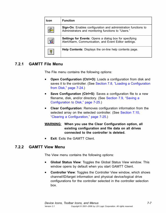
Device Icons, Toolbar Icons, and Menus 7-7Version 3.1 Copyright © 2001�2006 by LSI Logic Corporation. All rights reserved.
7.2.1 GAMTT File Menu
The File menu contains the following options:
• Open Configuration (Ctrl+O): Loads a configuration from disk and saves it to the controller. (See Section 7.8, �Loading a Configuration from Disk,� page 7-24.)
• Save Configuration (Ctrl+S): Saves a configuration file to a new filename, disk, and/or directory. (See Section 7.9, �Saving a Configuration to Disk,� page 7-25.)
• Clear Configuration: Removes configuration information from the selected array on the selected controller. (See Section 7.10, �Clearing a Configuration,� page 7-25.)
WARNING: When you use the Clear Configuration option, all existing configuration and file data on all drives connected to the controller is deleted.
• Exit: Exits the GAMTT Client.
7.2.2 GAMTT View Menu
The View menu contains the following options:
• Global Status View: Toggles the Global Status View window. This window opens by default when you start GAMTT Client.
• Controller View: Toggles the Controller View window, which shows channel/ID/target information and physical device/logical drive configurations for the controller selected in the controller selection box.
Sign-On: Enables configuration and administration functions to Administrators and monitoring functions to �Users.�
Settings for Events: Opens a dialog box for specifying Alert/Alarm, Communication, and Event Editor settings.
Help Contents: Displays the on-line help contents page.
Icon Function

7-8 Using GAMTT with Embedded MegaRAID SoftwareVersion 3.1 Copyright © 2001�2006 by LSI Logic Corporation. All rights reserved.
• Log Information Viewer: Toggles the Log Information Viewer, which shows a log of recent system error and status event messages. The Log Information Viewer opens by default when you start GAMTT Client.
• Foreground Initialization Status: Displays the progress (percent complete) of a currently running full foreground initialization of one or more drives.
• Rebuild Status: Displays the progress (percent complete) of a currently running device rebuild.
• Consistency Check Status: Displays the progress (percent complete) of a currently running logical drive consistency check.
7.2.3 GAMTT Administration Menu
The Administration menu contains the following options:
• Sign On: Enables Administrators to access GAMTT configuration and administration functions by using an appropriate username plus a password. Enables Users to monitor system status.
• Define Server Groups: Sets up server groups and individual server names or IP addresses within each group.
• Select Current Server Group (Ctrl+G): Displays the current contents of the server selection box located in the Global Array Manager window. Functions in the same way as directly selecting the server selection box.
• Select Current Controller (Ctrl+C): Displays the current contents of the controller selection box located in the Global Array Manager window. Functions in the same way as directly selecting the controller selection box.
• RAID Assist: Starts the RAID Assist configuration utility. Facilitates configuration tasks using either one-step �automatic� configuration, a configuration �wizard� assistant, or a manual (advanced level) configuration option allowing more control over configuration parameters.
• Controller Options: Enables you to set various parameters, such as cache line size, for the selected disk array controller.
• Scan Devices: Scans for recently added devices that are not currently identified within GAMTT Client.
Configuration 7-9Version 3.1 Copyright © 2001�2006 by LSI Logic Corporation. All rights reserved.
• Settings: Opens a dialog box in which you can specify Alert/Alarm, Communication, and Event Editor settings. These settings include type of alarm (pager, fax, E-mail, etc.), modem baud rate, COM port, stop bits, data bits, parity, and event severity level.
7.2.4 GAMTT Window Menu and Help Menu
These are the standard Window and Help menus used in all Microsoft Windows applications.
7.3 Configuration
You can use the GAMTT Client for the following configuration activities:
• Setting or modifying controller options
• Creating or deleting disk arrays, hot spares, and logical drives
• Loading a configuration from disk and saving it to the controller
You can use the convenient RAID Assist utility to create simple storage configurations automatically. For more complex configurations, RAID Assist allows you to customize the configuration parameters according to your needs. You can create up to two arrays if the SATA enclosure supports four SATA drives. RAID levels 0, 1, and 10 are supported, with up to eight disk drives total.
The GAMTT Client Configuration Lock feature temporarily disables write access on a controller system during critical activities such as changing controller options, creating or deleting arrays, and clearing configurations. This prevents two or more users with administrator privileges from accidentally trying to change the same controller configurations at the same time.
Configuration Lock is activated when the first user initiates a critical activity such as expanding the capacity of an array. Other �administrator� users are locked out of that controller system until the critical activity is completed. The following message appears (Figure 7.3) to notify you that a Configuration Lock is in effect.

7-10 Using GAMTT with Embedded MegaRAID SoftwareVersion 3.1 Copyright © 2001�2006 by LSI Logic Corporation. All rights reserved.
Figure 7.3 Configuration Lock Notification
Once the user with the lock has completed the critical activity, the controller system is automatically unlocked.
7.3.1 Setting and Changing Controller Options
To set or modify Controller options, follow these steps:
1. Select Administration -> Controller Options to open the Controller Options dialog box (Figure 7.4).
Figure 7.4 Controller Options Dialog Box
2. Make changes as needed to any of the parameters.
3. Click OK to accept the changes, or click Cancel to exit without saving.
Here are descriptions of the parameters listed in the Controller Options dialog box.
• Rebuild Rate. Select the rebuild rate for drives connected to the selected controller. The rebuild rate is the percentage of system
Running RAID Assist 7-11Version 3.1 Copyright © 2001�2006 by LSI Logic Corporation. All rights reserved.
resources dedicated to rebuilding a failed drive. To change the Rebuild rate, type a number in the box or click the up and down arrows. The higher the number, the faster the rebuild rate.
• Auto Rebuild. Select On to have failed drives rebuilt automatically when replaced with a new drive. Select Off (the default) to require a manual rebuild command for a failed drive.
• New Device. Select Auto Configuration to allow new devices to be configured automatically. Select Force to Ctrl-M to use the BIOS Configuration Utility to configure arrays and logical drives.
• Check Consistency State. Select Fix and Report to have the controller fix consistency errors automatically from the redundancy data in a RAID 1 array. Select Report Only to have the controller report on errors only, allowing you to decide whether to fix the errors.
• Fast Initialization. Select Enable (the default) to allow initialization of the logical drive by writing zeros to the first 100 MB of the drive, which takes much less time than a full initialization. Select Disabled to require a full initialization of the entire logical drive.
• BIOS State. Select Enabled to allow the option ROM to run and to support INT13.
• Stop On Error. Select Yes to make the BIOS stop in case of a problem with the configuration. This gives you the option to enter the configuration utility to resolve the problem. The default is No.
7.4 Running RAID Assist
RAID Assist is the GAMTT Client�s �wizard� for setting up and configuring new logical drives and disk arrays.
In its simplest form, RAID Assist provides an Auto Configuration option which configures all available drives into an optimal configuration. RAID Assist�s Assisted Configuration sets up a new array according to predefined parameters, and asks the user questions to gather the key information necessary to build the array.
The Manual Configuration option allows additional control over logical drive setup parameters.

7-12 Using GAMTT with Embedded MegaRAID SoftwareVersion 3.1 Copyright © 2001�2006 by LSI Logic Corporation. All rights reserved.
7.4.1 Opening RAID Assist
To open RAID Assist, select Administration->RAID Assist or click the
RAID assist icon .
The RAID Assist �Welcome� dialog box appears (Figure 7.5).
Figure 7.5 RAID Assist �Welcome� Dialog Box
In the RAID Assist �Welcome� dialog box, do one of the following:
• Click Automatic Configuration if you want to provide only minimal input and allow RAID Assist to set up an optimal configuration automatically.
• Click Assisted Configuration if you want RAID Assist to lead you step-by-step through the configuration.
• Click Manual Configuration if you want full control over the configuration setup.
• Click Cancel to exit RAID Assist without any changes.
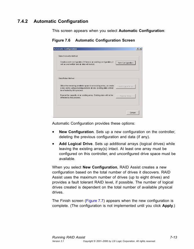
Running RAID Assist 7-13Version 3.1 Copyright © 2001�2006 by LSI Logic Corporation. All rights reserved.
7.4.2 Automatic Configuration
This screen appears when you select Automatic Configuration:
Figure 7.6 Automatic Configuration Screen
Automatic Configuration provides these options:
• New Configuration. Sets up a new configuration on the controller, deleting the previous configuration and data (if any).
• Add Logical Drive. Sets up additional arrays (logical drives) while leaving the existing array(s) intact. At least one array must be configured on this controller, and unconfigured drive space must be available.
When you select New Configuration, RAID Assist creates a new configuration based on the total number of drives it discovers. RAID Assist uses the maximum number of drives (up to eight drives) and provides a fault tolerant RAID level, if possible. The number of logical drives created is dependent on the total number of available physical drives.
The Finish screen (Figure 7.7) appears when the new configuration is complete. (The configuration is not implemented until you click Apply.)

7-14 Using GAMTT with Embedded MegaRAID SoftwareVersion 3.1 Copyright © 2001�2006 by LSI Logic Corporation. All rights reserved.
Figure 7.7 Automatic Configuration->New Configuration->Finish
Do the following when the Finish screen appears:
1. Examine the Configuration Summary for details about the configuration that RAID Assist is creating.
2. If you want to start over, click Back or Cancel, or click the Welcome tab.
If you want to know more about the configuration before it is applied to the controller, click Details. You will be taken to an equivalent of the Disk Arrays page as shown in Manual Configuration, except that you can only view the information.
3. To accept the configuration as presented, click Apply on the Finish screen.
A warning confirmation box appears.
4. Type YES and click OK if you are sure you want to apply the new configuration and overwrite the old one. If you�re not sure, click Cancel.
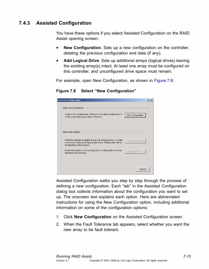
Running RAID Assist 7-15Version 3.1 Copyright © 2001�2006 by LSI Logic Corporation. All rights reserved.
7.4.3 Assisted Configuration
You have these options if you select Assisted Configuration on the RAID Assist opening screen:
• New Configuration. Sets up a new configuration on the controller, deleting the previous configuration and data (if any).
• Add Logical Drive. Sets up additional arrays (logical drives) leaving the existing array(s) intact. At least one array must be configured on this controller, and unconfigured drive space must remain.
For example, open New Configuration, as shown in Figure 7.8:
Figure 7.8 Select �New Configuration�
Assisted Configuration walks you step by step through the process of defining a new configuration. Each �tab� in the Assisted Configuration dialog box collects information about the configuration you want to set up. The onscreen text explains each option. Here are abbreviated instructions for using the New Configuration option, including additional information on some of the configuration options:
1. Click New Configuration on the Assisted Configuration screen.
2. When the Fault Tolerance tab appears, select whether you want the new array to be fault tolerant.

7-16 Using GAMTT with Embedded MegaRAID SoftwareVersion 3.1 Copyright © 2001�2006 by LSI Logic Corporation. All rights reserved.
If you select Yes, RAID Assist selects a RAID 1 array. If you select No, RAID Assist selects a RAID 0 array.
3. Click Next.
The RAID Level tab appears. Since Embedded MegaRAID Software supports only RAID 0, RAID 1, and RAID 10 arrays, the RAID level was already decided on the Fault Tolerance tab.
4. Click Next.
5. When the Logical Drives tab appears, select the number of logical drives you want to create and the percentage of capacity you want to use.
For RAID 0 and RAID 1 arrays, Embedded MegaRAID Software supports up to 8 logical drives. For RAID 10 arrays, it supports one logical drive. You would normally use 100% of the available capacity (the default).
6. Select whether you want the logical drive(s) to be initialized. The logical drives are initialized after the configuration has been applied.
� Select Yes to request a full foreground initialization of logical drives once the new configuration is applied. You cannot use the drives until initialization is complete.
� Select No if you do not want the logical drives to be initialized.
7. Click Next.
8. When the Optimization tab appears, select a Stripe Size from the drop-down list.
9. Click Next. The Finish screen appears (Figure 7.9).
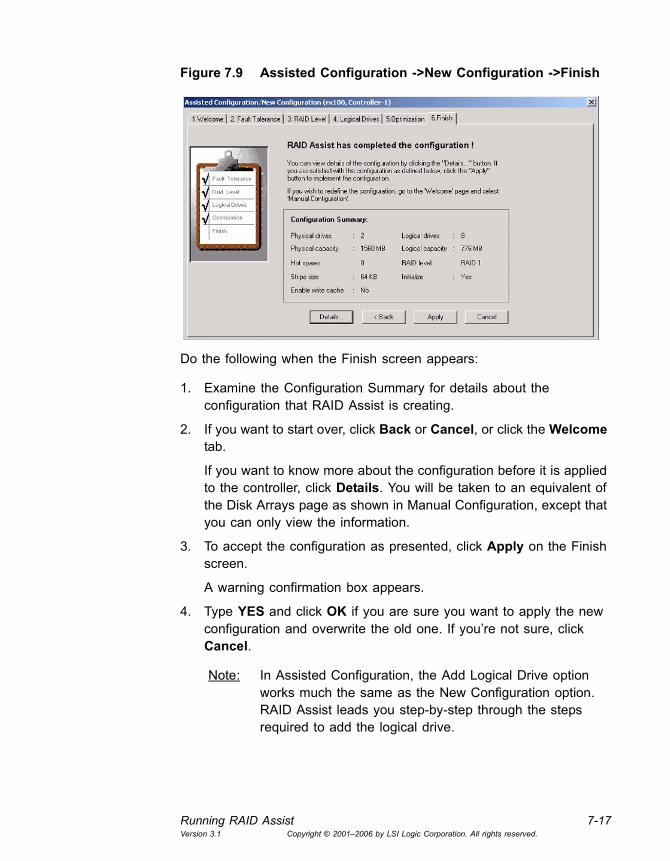
Running RAID Assist 7-17Version 3.1 Copyright © 2001�2006 by LSI Logic Corporation. All rights reserved.
Figure 7.9 Assisted Configuration ->New Configuration ->Finish
Do the following when the Finish screen appears:
1. Examine the Configuration Summary for details about the configuration that RAID Assist is creating.
2. If you want to start over, click Back or Cancel, or click the Welcome tab.
If you want to know more about the configuration before it is applied to the controller, click Details. You will be taken to an equivalent of the Disk Arrays page as shown in Manual Configuration, except that you can only view the information.
3. To accept the configuration as presented, click Apply on the Finish screen.
A warning confirmation box appears.
4. Type YES and click OK if you are sure you want to apply the new configuration and overwrite the old one. If you�re not sure, click Cancel.
Note: In Assisted Configuration, the Add Logical Drive option works much the same as the New Configuration option. RAID Assist leads you step-by-step through the steps required to add the logical drive.
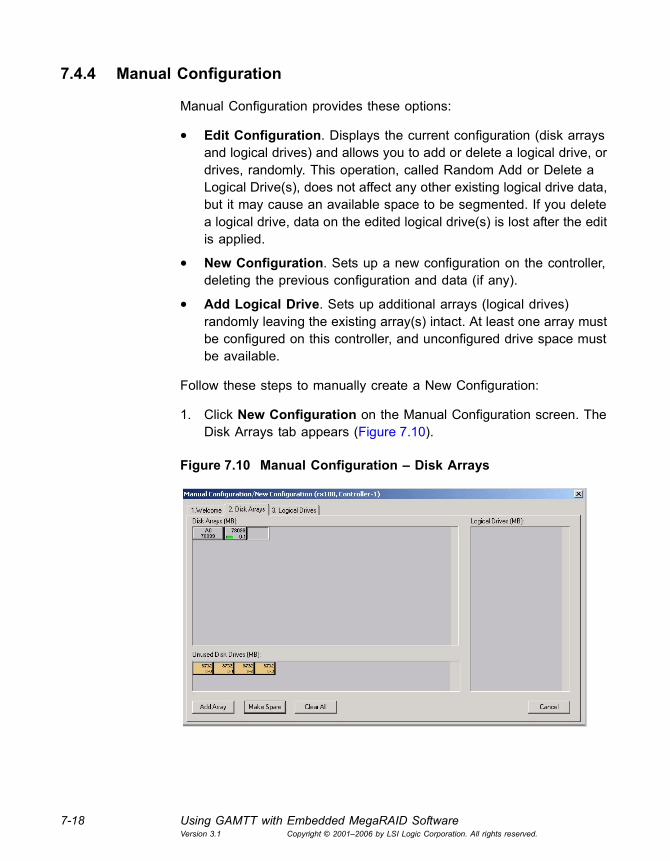
7-18 Using GAMTT with Embedded MegaRAID SoftwareVersion 3.1 Copyright © 2001�2006 by LSI Logic Corporation. All rights reserved.
7.4.4 Manual Configuration
Manual Configuration provides these options:
• Edit Configuration. Displays the current configuration (disk arrays and logical drives) and allows you to add or delete a logical drive, or drives, randomly. This operation, called Random Add or Delete a Logical Drive(s), does not affect any other existing logical drive data, but it may cause an available space to be segmented. If you delete a logical drive, data on the edited logical drive(s) is lost after the edit is applied.
• New Configuration. Sets up a new configuration on the controller, deleting the previous configuration and data (if any).
• Add Logical Drive. Sets up additional arrays (logical drives) randomly leaving the existing array(s) intact. At least one array must be configured on this controller, and unconfigured drive space must be available.
Follow these steps to manually create a New Configuration:
1. Click New Configuration on the Manual Configuration screen. The Disk Arrays tab appears (Figure 7.10).
Figure 7.10 Manual Configuration � Disk Arrays

Running RAID Assist 7-19Version 3.1 Copyright © 2001�2006 by LSI Logic Corporation. All rights reserved.
Each disk array is represented by two lines in the Disk Arrays area of the screen (upper left, Figure 7.10). Logical drives (if any are configured) appear on the right side of the screen.
2. Select an unused drive and drag it to the Disk Array A0 section. The drive will become part of a disk array referred to as �A0.�
3. Select other unused drives and drag them to Disk Array A0, or click Add Array to create a row for Disk Array A1, then drag unused drives to A1 if you wish.
4. If you want to start over, click Clear All and start again.
5. When you have defined the disk array groups, click the Logical Drives tab to continue with logical drive setup (Figure 7.11)
Figure 7.11 Manual Configuration � Logical Drives
The Logical Drives tab in Manual Configuration is where you configure your disk arrays into logical drives.
Do the following to configure logical drives:
1. Select a RAID level for the first logical drive. Only RAID levels compatible with the current configuration are available in the list.
Embedded MegaRAID Software supports RAID 0, RAID 1, and RAID 10. RAID 10 arrays can have one logical drive defined per array.

7-20 Using GAMTT with Embedded MegaRAID SoftwareVersion 3.1 Copyright © 2001�2006 by LSI Logic Corporation. All rights reserved.
2. Type the amount of available logical or physical capacity for this logical drive. Do not change the default sizes if the total configuration will have only one logical drive that uses all available capacity. If you intend to create additional logical drives now or later, type a smaller number to reserve the desired amount of capacity.
Note: When creating a random logical drive, if there are a few existing segmented spaces, the largest space is used to create the logical drive.
3. Check the Init Drive box if you want this logical drive to be fully initialized at the conclusion of the configuration (recommended).
4. Select a stripe size. The stripe size is defined as the size, in Kbytes, of a single I/O operation. A stripe of data (data residing in actual physical disk sectors, which are logically ordered first to last) is divided over all disks in the drive group.
When selecting a stripe size of less than 64 KB, the active cache line size changes from 64 KB to 8 KB. A Warning dialog box appears with the following message, �Due to a Stripe Size selection of less than 64KB, 8KB Cache Line Size will be used.�
If you select Yes, the new configuration is applied and an 8 KB cache line size is active.
If you select No, the Logical Drives page of the Manual Configuration Wizard opens. You can change the stripe size in order to obtain the desired cache line size.
5. Click Add Drive to register the new logical drive.
6. Click Apply to save the configuration if you are finished setting up logical drives, or repeat the steps above to set up additional logical drives.
7. Click Apply when you have finished setting up logical drives.

Adding a Logical Drive 7-21Version 3.1 Copyright © 2001�2006 by LSI Logic Corporation. All rights reserved.
Figure 7.12 shows example of a completed Manual configuration:
Figure 7.12 Sample Manual Configuration Just Before �Apply�
Note: In Manual Configuration, the Add Logical Drive option works much the same as what was shown above. In each case, RAID Assist shows you the disk arrays and logical drives and allows you to add to the configuration without risking existing data.
7.5 Adding a Logical Drive
You can add a logical drive to utilize available space in an existing array. Data on existing logical drives is not affected when you do this.
To add a logical drive, follow these steps:
1. Select Administration->RAID Assist on the menu bar, or click the
RAID Assist icon .
2. Click Manual Configuration.
3. Click Add Logical Drive. The Manual Configuration Logical Drives tab appears (see Figure 7.13).

7-22 Using GAMTT with Embedded MegaRAID SoftwareVersion 3.1 Copyright © 2001�2006 by LSI Logic Corporation. All rights reserved.
Figure 7.13 Logical Drives Tab
4. Click Add Drive. If there are several available segmented spaces, the largest space is used to create a new logical drive.
Figure 7.14 Add Logical Drive(s)
5. Select a RAID level for your new logical drive.
6. Type the desired amount of available logical or physical capacity for this logical drive.
7. Check the Init Drive box if you want this logical drive to be fully initialized at the conclusion of the configuration.
8. Select a stripe size.

Deleting a Logical Drive 7-23Version 3.1 Copyright © 2001�2006 by LSI Logic Corporation. All rights reserved.
9. Click Apply to save your new configuration.
A warning confirmation box appears.
10. Type YES and click OK if you are sure you want to apply the new configuration and overwrite the old.
7.6 Deleting a Logical Drive
To delete a logical drive, follow these steps:
1. Back up all user data on the drive you intend to delete.
2. Select Administration->RAID Assist on the menu bar, or click the
RAID Assist icon .
3. Click Manual Configuration, then Edit Configuration.
4. Select the Logical Drives tab (see Figure 7.15).
Figure 7.15 Deleting a Logical Drive
5. Click Delete Drive. The last logical drive created will be the first deleted, and so on.
6. Repeat Step 5, if desired, to delete more logical drives.
7. Click Apply to save the new configuration.
8. See Section 7.4.4, �Manual Configuration,� page 7-18, for instructions on reconfiguring the available space.

7-24 Using GAMTT with Embedded MegaRAID SoftwareVersion 3.1 Copyright © 2001�2006 by LSI Logic Corporation. All rights reserved.
7.7 Creating Hot Spares
Embedded MegaRAID Software supports global hot spares. A global hot spare can automatically replace a failed disk in any logical drive.
To create a global hot spare, do the following:
1. Select Administration->RAID Assist on the menu bar, or click the
RAID Assist icon .
2. Click Manual Configuration.
3. Click Edit Configuration.
4. Click the Disk Array tab.
5. Select a physical drive in Unused Disk Drives/Global Hot Spares pane at the bottom of the screen.
6. Click Make Spare.
A global hot spare is created, and a white plus sign in the disk icon indicates that the physical disk drive has changed to a global hot spare.
7.8 Loading a Configuration from Disk
To load a previously-saved controller configuration from disk, follow these steps:
1. Select File -> Open Configuration.
2. In the Open Configuration dialog box, select the configuration file you want to open to save to the controller.
3. Click Open to access the configuration (.gcf) file.
A warning message appears to remind you that changing the configuration will destroy existing data.
4. Type YES and click OK if you are sure you want to apply the new configuration and overwrite the old one. Click Cancel to stop without applying the new controller configuration.

Saving a Configuration to Disk 7-25Version 3.1 Copyright © 2001�2006 by LSI Logic Corporation. All rights reserved.
7.9 Saving a Configuration to Disk
To save a controller configuration file, follow these steps:
1. Select File -> Save Configuration.
2. In the Save Configuration dialog box, type a name for the configuration file you want to save.
3. Click Save to save the configuration file.
The controller configuration file (.gcf) is saved.
7.10 Clearing a Configuration
To clear a controller configuration, follow these steps:
1. Select File->Clear Configuration.
2. Select the disk array(s) that you want to delete.
3. Click OK to clear the configuration.
A caution message box appears.
4. Click Yes to continue.
A warning message box appears.
5. To confirm your decision to clear the selected configuration, type YES and click OK, or click Cancel to stop.
7.11 Monitoring Activities
GAMTT Client software supports the following monitoring activities:
• Monitoring events (messages) sent by various servers to the client workstation(s)
• Monitoring logical drives, disk drives, and other physical devices
• Monitoring the status of ongoing processes, such as initialization, rebuild, and consistency check

7-26 Using GAMTT with Embedded MegaRAID SoftwareVersion 3.1 Copyright © 2001�2006 by LSI Logic Corporation. All rights reserved.
7.11.1 Monitoring Events
Embedded MegaRAID Software monitors the activity and performance of disk drives, controllers, and other storage devices. When an activity results in an �event�, the event is sent to workstations that are running GAMTT Client. There are various categories of events ranging from �serious� events such as a disk failure to �informational� events such as the completion of a consistency check. For descriptions of all events, see Appendix A, �Event and Message Information.�
Events are displayed in the Log Information Viewer, which is described in Section 3.2.1.2, �Log Information Viewer.�
LSI Logic recommends that you leave the GAMTT Client running as long as there are servers you want to monitor. If you exit, you cannot receive event information from GAMTT Server unless you restart GAMTT Client and reconnect to the server(s).
7.11.2 Opening the Log Information Viewer
The Log Information Viewer opens when you start GAMTT and it detects one or more controllers (see Section 3.2.1.2, �Log Information Viewer,� page 3-4). The viewer displays a chronological log of all the events that occur while this session of the program is executing. By default, the log file is named gam2cl.log. The log file name and location can be changed on the Alert Preferences page or in the gam2cl.ini file.
7.11.3 Opening an Event Information Window
You can view more information about any event displayed in the Log Information Viewer by opening an event information window. Appendix A lists all event descriptions, causes (details), and actions.
To open the event information window for a particular event, double-click the event entry in the Log Information Viewer. An event information window for your selected event is displayed. Figure 7.16 shows an example:

Monitoring Activities 7-27Version 3.1 Copyright © 2001�2006 by LSI Logic Corporation. All rights reserved.
Figure 7.16 Event Information Window
The Event ID and Severity Level are displayed in the window�s title bar. The most useful information fields are:
� CAUSE. Possible reasons that the event occurred, and
� REQUIRED ACTION. What you should do in response to this message. Informational messages usually have no required actions. Critical, Serious, Error, and Warning messages may specify useful required actions.
Click OK to close the event information window.
7.11.4 Monitoring Physical Devices and Logical Drives
This section describes how the GAMTT Client monitors physical devices and logical drives.
The Controller View window shows which physical devices are associated with each controller channel. Each stack of drives represents the physical drives connected to a single channel on the controller.
The Device Information window (Figure 7.17) opens when you double-click a physical device icon and displays information about the physical device.

7-28 Using GAMTT with Embedded MegaRAID SoftwareVersion 3.1 Copyright © 2001�2006 by LSI Logic Corporation. All rights reserved.
Figure 7.17 Device Information
Most of this information is self-explanatory. Note the following:
• To change the Write Cache or Read-ahead settings, select On or Off from the drop-down menus, and click Apply.
• If the current Status of the disk is Failed, a failure indicator is listed (see Appendix A for a list of error codes).
• If the disk status is Rebuild, the Rebuild button may be available so that you can initiate a physical device rebuild.
• If the Error count is greater than zero, you can click the Error Details button to view the Error Log Information screen (Figure 7.18).
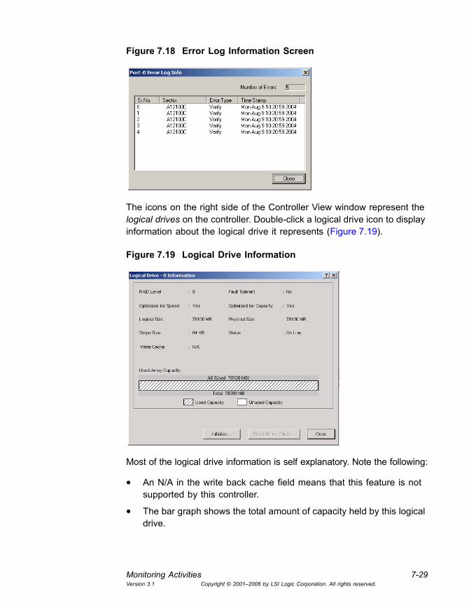
Monitoring Activities 7-29Version 3.1 Copyright © 2001�2006 by LSI Logic Corporation. All rights reserved.
Figure 7.18 Error Log Information Screen
The icons on the right side of the Controller View window represent the logical drives on the controller. Double-click a logical drive icon to display information about the logical drive it represents (Figure 7.19).
Figure 7.19 Logical Drive Information
Most of the logical drive information is self explanatory. Note the following:
• An N/A in the write back cache field means that this feature is not supported by this controller.
• The bar graph shows the total amount of capacity held by this logical drive.
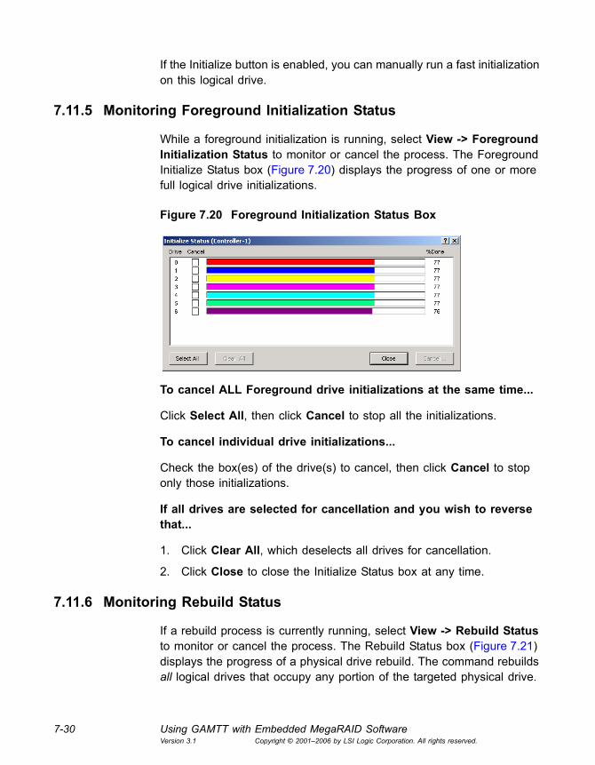
7-30 Using GAMTT with Embedded MegaRAID SoftwareVersion 3.1 Copyright © 2001�2006 by LSI Logic Corporation. All rights reserved.
If the Initialize button is enabled, you can manually run a fast initialization on this logical drive.
7.11.5 Monitoring Foreground Initialization Status
While a foreground initialization is running, select View -> Foreground Initialization Status to monitor or cancel the process. The Foreground Initialize Status box (Figure 7.20) displays the progress of one or more full logical drive initializations.
Figure 7.20 Foreground Initialization Status Box
To cancel ALL Foreground drive initializations at the same time...
Click Select All, then click Cancel to stop all the initializations.
To cancel individual drive initializations...
Check the box(es) of the drive(s) to cancel, then click Cancel to stop only those initializations.
If all drives are selected for cancellation and you wish to reverse that...
1. Click Clear All, which deselects all drives for cancellation.
2. Click Close to close the Initialize Status box at any time.
7.11.6 Monitoring Rebuild Status
If a rebuild process is currently running, select View -> Rebuild Status to monitor or cancel the process. The Rebuild Status box (Figure 7.21) displays the progress of a physical drive rebuild. The command rebuilds all logical drives that occupy any portion of the targeted physical drive.
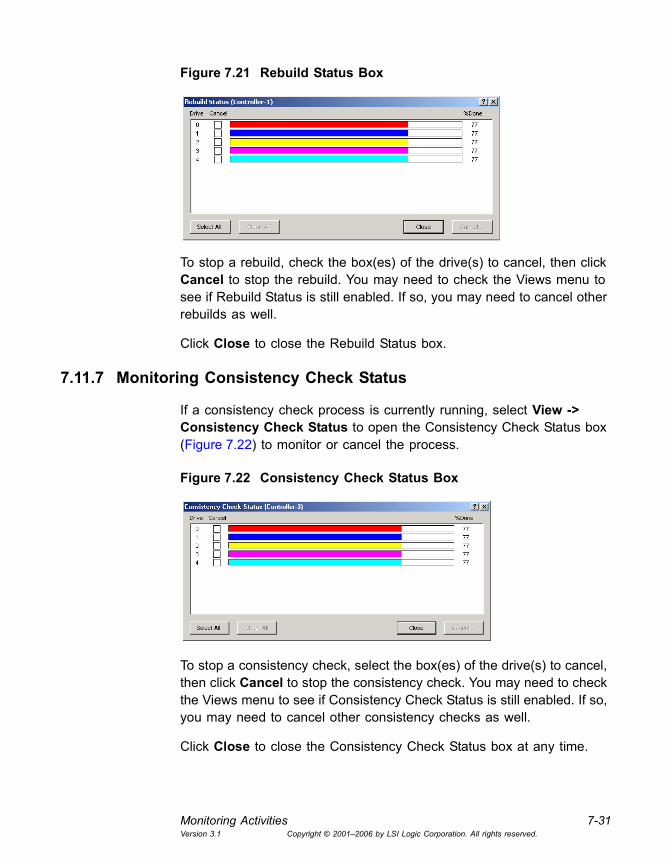
Monitoring Activities 7-31Version 3.1 Copyright © 2001�2006 by LSI Logic Corporation. All rights reserved.
Figure 7.21 Rebuild Status Box
To stop a rebuild, check the box(es) of the drive(s) to cancel, then click Cancel to stop the rebuild. You may need to check the Views menu to see if Rebuild Status is still enabled. If so, you may need to cancel other rebuilds as well.
Click Close to close the Rebuild Status box.
7.11.7 Monitoring Consistency Check Status
If a consistency check process is currently running, select View -> Consistency Check Status to open the Consistency Check Status box (Figure 7.22) to monitor or cancel the process.
Figure 7.22 Consistency Check Status Box
To stop a consistency check, select the box(es) of the drive(s) to cancel, then click Cancel to stop the consistency check. You may need to check the Views menu to see if Consistency Check Status is still enabled. If so, you may need to cancel other consistency checks as well.
Click Close to close the Consistency Check Status box at any time.
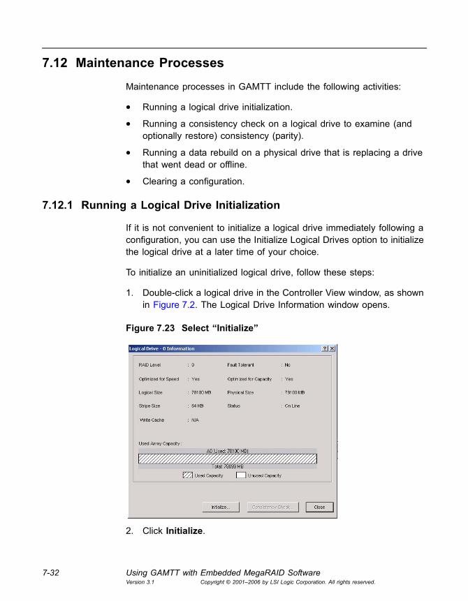
7-32 Using GAMTT with Embedded MegaRAID SoftwareVersion 3.1 Copyright © 2001�2006 by LSI Logic Corporation. All rights reserved.
7.12 Maintenance Processes
Maintenance processes in GAMTT include the following activities:
• Running a logical drive initialization.
• Running a consistency check on a logical drive to examine (and optionally restore) consistency (parity).
• Running a data rebuild on a physical drive that is replacing a drive that went dead or offline.
• Clearing a configuration.
7.12.1 Running a Logical Drive Initialization
If it is not convenient to initialize a logical drive immediately following a configuration, you can use the Initialize Logical Drives option to initialize the logical drive at a later time of your choice.
To initialize an uninitialized logical drive, follow these steps:
1. Double-click a logical drive in the Controller View window, as shown in Figure 7.2. The Logical Drive Information window opens.
Figure 7.23 Select �Initialize�
2. Click Initialize.

Maintenance Processes 7-33Version 3.1 Copyright © 2001�2006 by LSI Logic Corporation. All rights reserved.
A Warning message dialog box appears for confirmation.
3. Type YES to confirm the initialization and click OK.
The Initialize Status Dialog box opens. See Section 7.11.5, �Monitoring Foreground Initialization Status,� page 7-30, for more information.
7.12.2 Running a Logical Drive Consistency Check
You should periodically run a consistency check on each fault tolerant logical drive to determine whether consistency data has become corrupted and needs to be restored. It is especially important to do this if you think the logical drive consistency data may be corrupted.
To run a logical drive consistency check, follow these steps:
1. Open the Controller View window by double-clicking any server icon in the Global Status View, or by selecting View -> Controller View...
2. Double-click a logical drive in the Logical Drives list on the right side of the Controller View window.
The Logical Drive Information window opens.
Figure 7.24 Select �Consistency Check�
3. Click Consistency Check. A Consistency Check warning dialog box appears.

7-34 Using GAMTT with Embedded MegaRAID SoftwareVersion 3.1 Copyright © 2001�2006 by LSI Logic Corporation. All rights reserved.
4. Click Yes to restore consistency during the process, or click No if you just want to complete the consistency check.
Caution: Use the Yes option with caution! If the consistency data on a logical drive is badly corrupted, the real data may become corrupted if you attempt to restore consistency.
There is no risk of data loss if you select No.
5. When the Consistency Check Status box appears, either close it or leave it open until the consistency check has completed. (See Section 7.11.7, �Monitoring Consistency Check Status,� page 7-31.)
You can run multiple consistency checks with MegaRAID controllers.
7.12.3 Running a Device Rebuild
If a single drive in a fault tolerant system fails, the system is protected from data loss. The failed drive must be replaced, and the failed drive�s data must be rebuilt on a new drive to restore the system to fault tolerance.
The device rebuild function performs this task. A failed drive�s data can be rebuilt to the original drive, if this drive is still functional, or to a new drive inserted in place of the failed drive, or to a hot spare drive. To rebuild a failed drive, follow these steps:
1. Remove and reinsert the drive that caused the failure (if it is a good drive), or replace it with a new drive of equal or greater capacity.
2. Double-click the relevant physical device in the Controller View window.
The Disk Device Information dialog box opens, and the Rebuild button should be available (Figure 7.25).
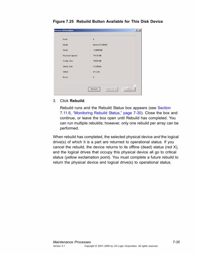
Maintenance Processes 7-35Version 3.1 Copyright © 2001�2006 by LSI Logic Corporation. All rights reserved.
Figure 7.25 Rebuild Button Available for This Disk Device
3. Click Rebuild.
Rebuild runs and the Rebuild Status box appears (see Section 7.11.6, �Monitoring Rebuild Status,� page 7-30). Close the box and continue, or leave the box open until Rebuild has completed. You can run multiple rebuilds; however, only one rebuild per array can be performed.
When rebuild has completed, the selected physical device and the logical drive(s) of which it is a part are returned to operational status. If you cancel the rebuild, the device returns to its offline (dead) status (red X), and the logical drives that occupy this physical device all go to critical status (yellow exclamation point). You must complete a future rebuild to return the physical device and logical drive(s) to operational status.

7-36 Using GAMTT with Embedded MegaRAID SoftwareVersion 3.1 Copyright © 2001�2006 by LSI Logic Corporation. All rights reserved.

Global Array Manager Transition Tool Client Software User�s Guide A-1Version 3.1 Copyright © 2001�2006 by LSI Logic Corporation. All rights reserved.
Appendix AEvent and Message Information
This appendix has information about GAMTT events and Spy messages.
A.1 Overview
Global Array Manager Transition Tool provides information about drive and controller failures, as well as maintaining an event log. GAMTT classifies the events it records into five severity levels described in Table A.1. All event information can also be found in the text file EventDef.txt in the GAMTT Files folder of the GAMTT directory.
Table A.1 Severity Level Priorities and Descriptions
Severity Type Description
0 Critical Controller failure.
1 Serious The failure of a major component within the array enclosure. For example, a power supply, fan or physical drive.
2 Error A consistency check fails, or a rebuild on a drive stopped because of errors.
3 Warning Global Array Manager has failed to kill a drive, or failed to start a rebuild.
4 Informational Messages such as sign-ons and system startups. When a consistency check or a rebuild has finished, for example, or a physical drive has been put on standby.

A-2 Event and Message InformationVersion 3.1 Copyright © 2001�2006 by LSI Logic Corporation. All rights reserved.
A.2 GAMTT Events
Table A.2 GAMTT Events for PCI Controllers
ID Severity Description Details Actions
1 4 A physical disk has been placed online.
Rebuild completed. Physical disk was configured. Manual on-line was done.
None.
2 4 A physical disk has been added as a hot spare.
Device was configured. Manual hot spare was done. Automatic hot spare was done. 'Raidbld' made it a hot spare.
None
3 2 Physical disk error found.
A bad sector was found on the physi-cal disk. Mechanical failure on the physical disk. Host SCSI device detected illegal instruction. Target device generated unknown phase sequence.
If problem occurs fre-quently, replace the physical disk. Contact your service representative.
4 2 Physical disk PFA condition found; this disk may fail soon.
Physical disk predicted some future failure. External RAID logical device may have become critical.
Refer to the enclosure manufacturer's service manual.
5 4 An automatic rebuild has started.
A physical device failed and a spare was available. A physical device failed and no spare was available. A spare was added.
None.
6 4 A rebuild has started.
Client started the rebuild on user's request. User replaced the failed device and 'raidbld' started the rebuild.
None.
7 4 Rebuild is over. Rebuild completed successfully. None.
8 3 Rebuild is cancelled. User cancelled the rebuild. Higher pri-ority rebuild started.
Restart the rebuild if required.
9 2 Rebuild stopped with an error.
Rebuild failed due to some unknown error on the controller.
Try rebuild again.
10 2 Rebuild stopped with an error. New physi-cal disk failed.
New physical device failed. New phys-ical device may not be compatible with MDAC hardware/firmware.
Replace the physical disk.
(Sheet 1 of 32)
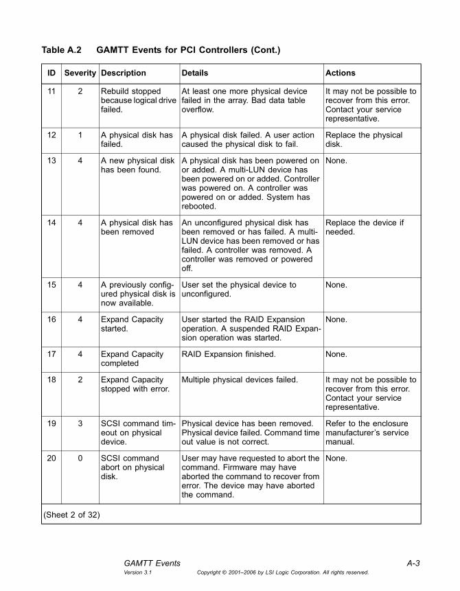
GAMTT Events A-3Version 3.1 Copyright © 2001�2006 by LSI Logic Corporation. All rights reserved.
11 2 Rebuild stopped because logical drive failed.
At least one more physical device failed in the array. Bad data table overflow.
It may not be possible to recover from this error. Contact your service representative.
12 1 A physical disk has failed.
A physical disk failed. A user action caused the physical disk to fail.
Replace the physical disk.
13 4 A new physical disk has been found.
A physical disk has been powered on or added. A multi-LUN device has been powered on or added. Controller was powered on. A controller was powered on or added. System has rebooted.
None.
14 4 A physical disk has been removed
An unconfigured physical disk has been removed or has failed. A multi-LUN device has been removed or has failed. A controller was removed. A controller was removed or powered off.
Replace the device if needed.
15 4 A previously config-ured physical disk is now available.
User set the physical device to unconfigured.
None.
16 4 Expand Capacity started.
User started the RAID Expansion operation. A suspended RAID Expan-sion operation was started.
None.
17 4 Expand Capacity completed
RAID Expansion finished. None.
18 2 Expand Capacity stopped with error.
Multiple physical devices failed. It may not be possible to recover from this error. Contact your service representative.
19 3 SCSI command tim-eout on physical device.
Physical device has been removed. Physical device failed. Command time out value is not correct.
Refer to the enclosure manufacturer�s service manual.
20 0 SCSI command abort on physical disk.
User may have requested to abort the command. Firmware may have aborted the command to recover from error. The device may have aborted the command.
None.
Table A.2 GAMTT Events for PCI Controllers (Cont.)
ID Severity Description Details Actions
(Sheet 2 of 32)
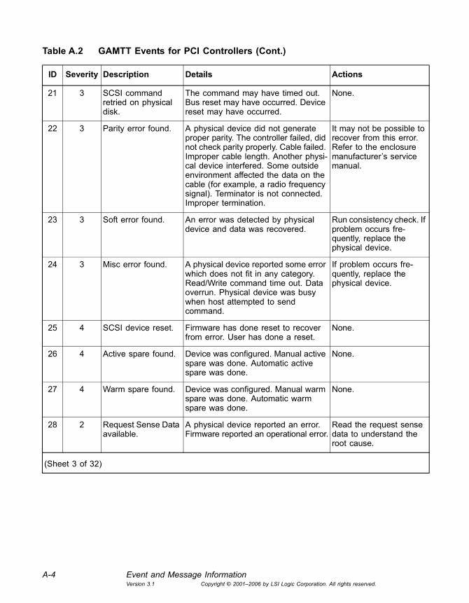
A-4 Event and Message InformationVersion 3.1 Copyright © 2001�2006 by LSI Logic Corporation. All rights reserved.
21 3 SCSI command retried on physical disk.
The command may have timed out. Bus reset may have occurred. Device reset may have occurred.
None.
22 3 Parity error found. A physical device did not generate proper parity. The controller failed, did not check parity properly. Cable failed. Improper cable length. Another physi-cal device interfered. Some outside environment affected the data on the cable (for example, a radio frequency signal). Terminator is not connected. Improper termination.
It may not be possible to recover from this error. Refer to the enclosure manufacturer�s service manual.
23 3 Soft error found. An error was detected by physical device and data was recovered.
Run consistency check. If problem occurs fre-quently, replace the physical device.
24 3 Misc error found. A physical device reported some error which does not fit in any category. Read/Write command time out. Data overrun. Physical device was busy when host attempted to send command.
If problem occurs fre-quently, replace the physical device.
25 4 SCSI device reset. Firmware has done reset to recover from error. User has done a reset.
None.
26 4 Active spare found. Device was configured. Manual active spare was done. Automatic active spare was done.
None.
27 4 Warm spare found. Device was configured. Manual warm spare was done. Automatic warm spare was done.
None.
28 2 Request Sense Data available.
A physical device reported an error. Firmware reported an operational error.
Read the request sense data to understand the root cause.
Table A.2 GAMTT Events for PCI Controllers (Cont.)
ID Severity Description Details Actions
(Sheet 3 of 32)

GAMTT Events A-5Version 3.1 Copyright © 2001�2006 by LSI Logic Corporation. All rights reserved.
29 4 Initialization started. Host started the initialization. Wait till the initialization is completed. If the system is shutdown before this process is completed, the physical device can be made useful only by rein-itializing it.
30 4 Initialization completed.
Physical device initialization com-pleted successfully.
None.
31 3 Initialization failed. Physical device could have some problems with supporting the SCSI format command.
Try to initialize again. Contact your service representative.
32 1 Initialization cancelled.
User cancelled the operation. Physical disk must be ini-tialized again or the physical disk cannot be used.
33 1 A physical disk failed because write recov-ery failed.
Write recovery process failed. Replace physical disk and rebuild it.
34 1 A physical disk failed because SCSI bus reset failed.
SCSI bus reset failed. Replace physical disk and rebuild it.
35 1 A physical disk failed because double check condition occurred.
Double check condition occurred. Replace physical disk and rebuild it.
36 1 A physical disk failed because device is missing.
Access to the physical disk failed. Replace physical disk and rebuild it.
37 1 A physical disk failed because of gross error on SCSI processor.
Gross error occurred to the onboard SCSI processor.
Replace physical disk and rebuild it.
38 1 A physical disk failed because of bad tag from the device.
The device responded with an invalid tag.
Replace physical disk and rebuild it.
Table A.2 GAMTT Events for PCI Controllers (Cont.)
ID Severity Description Details Actions
(Sheet 4 of 32)

A-6 Event and Message InformationVersion 3.1 Copyright © 2001�2006 by LSI Logic Corporation. All rights reserved.
39 1 A physical disk failed because command to the device timed out.
SCSI command timed out on the device.
Replace physical disk and rebuild it.
40 1 A physical disk failed because of the sys-tem reset.
System reset occurred. Replace physical disk and rebuild it.
41 1 A physical disk failed because of busy sta-tus or parity error.
The device returned a busy status. The SCSI transaction with the device met with a parity error.
Replace physical disk and rebuild it.
42 1 A physical disk was set to failed state by host.
Command from host set the physical disk to failed state.
Replace physical disk and rebuild it.
43 1 A physical disk failed because access to the device met with a selection time out.
Device disconnected or powered off. Bad device.
Replace physical disk and rebuild it. Check power and cabling.
44 1 A physical disk failed because of a sequence error in the SCSI bus phase handling.
Physical disk failure. Replace physical disk and rebuild it.
45 1 A physical disk failed because device returned an unknown status.
Bad physical disk or incompatible device.
Replace physical disk or the device and rebuild it.
46 1 A physical disk failed because device is not ready.
Device not spinning, just turned bad. Power to the device failed.
Replace physical disk and rebuild it. Check power and rebuild device.
47 1 A physical disk failed because device was not found on start up.
Device not connected. Device not responding. Clear configuration sus-pend mode command was invoked.
Check setup. Check the startup option parameters on the system.
48 1 A physical disk failed because write opera-tion of the 'Configuration On Disk' failed.
Bad physical disk. Device write protected.
Replace physical disk and rebuild it. Check the startup option parameters on the system.
Table A.2 GAMTT Events for PCI Controllers (Cont.)
ID Severity Description Details Actions
(Sheet 5 of 32)

GAMTT Events A-7Version 3.1 Copyright © 2001�2006 by LSI Logic Corporation. All rights reserved.
49 1 A physical disk failed because write opera-tion of 'Bad Data Table' failed.
Bad physical disk. Device write protected.
Replace physical disk and rebuild it. Check the star-tup option parameters on the system.
50 2 Physical disk status changed to offline.
None. None.
51 4 Physical disk status changed to hot spare.
None. None.
52 2 Physical disk status changed to rebuild.
None. None.
53 3 Physical device ID did not match.
None. None.
54 2 Physical disk failed to start.
None. Reseat the physical disk; replace the physical disk.
55 3 Physical disk negoti-ated different offset than config.
None. None.
56 3 Physical disk negoti-ated different bus width than config.
None. None.
57 1 Physical disk miss-ing on startup.
Physical disk missing. Replace the physical disk or power-on all enclosures.
58 3 Rebuild startup failed due to lower disk capacity.
Device capacity not sufficient for doing rebuild.
Replace with a disk hav-ing sufficient capacity.
59 3 Physical disk is switching from a channel to the other channel.
Physical disk removed or channel failed.
Check FC loop; replace physical disk if necessary.
60 2 Temporary-Dead physical drive is automatically made online.
Temporary-Dead state caused because of transient errors.
Analyze event log to find out why the drive was marked DEAD.
Table A.2 GAMTT Events for PCI Controllers (Cont.)
ID Severity Description Details Actions
(Sheet 6 of 32)
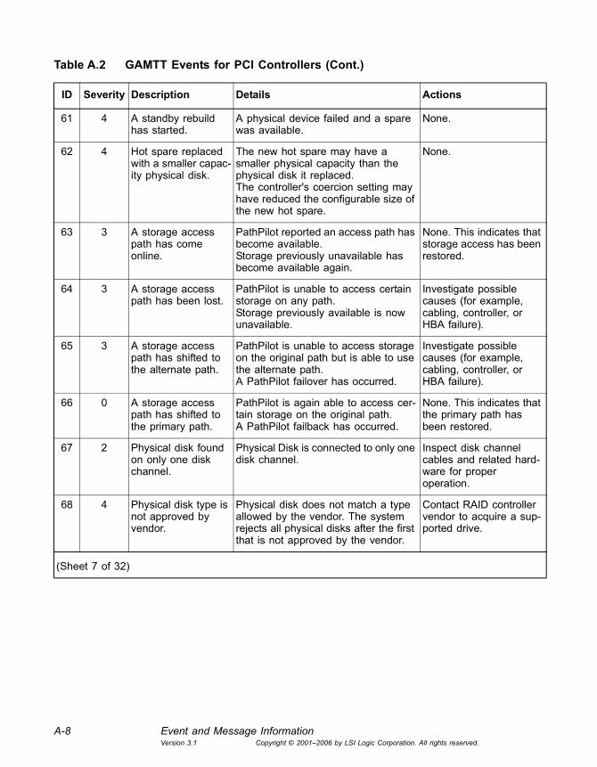
A-8 Event and Message InformationVersion 3.1 Copyright © 2001�2006 by LSI Logic Corporation. All rights reserved.
61 4 A standby rebuild has started.
A physical device failed and a spare was available.
None.
62 4 Hot spare replaced with a smaller capac-ity physical disk.
The new hot spare may have a smaller physical capacity than the physical disk it replaced.The controller's coercion setting may have reduced the configurable size of the new hot spare.
None.
63 3 A storage access path has come online.
PathPilot reported an access path has become available.Storage previously unavailable has become available again.
None. This indicates that storage access has been restored.
64 3 A storage access path has been lost.
PathPilot is unable to access certain storage on any path.Storage previously available is now unavailable.
Investigate possible causes (for example, cabling, controller, or HBA failure).
65 3 A storage access path has shifted to the alternate path.
PathPilot is unable to access storage on the original path but is able to use the alternate path.A PathPilot failover has occurred.
Investigate possible causes (for example, cabling, controller, or HBA failure).
66 0 A storage access path has shifted to the primary path.
PathPilot is again able to access cer-tain storage on the original path.A PathPilot failback has occurred.
None. This indicates that the primary path has been restored.
67 2 Physical disk found on only one disk channel.
Physical Disk is connected to only one disk channel.
Inspect disk channel cables and related hard-ware for proper operation.
68 4 Physical disk type is not approved by vendor.
Physical disk does not match a type allowed by the vendor. The system rejects all physical disks after the first that is not approved by the vendor.
Contact RAID controller vendor to acquire a sup-ported drive.
Table A.2 GAMTT Events for PCI Controllers (Cont.)
ID Severity Description Details Actions
(Sheet 7 of 32)
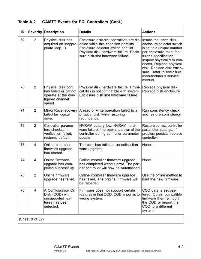
GAMTT Events A-9Version 3.1 Copyright © 2001�2006 by LSI Logic Corporation. All rights reserved.
69 2 Physical disk has acquired an inappro-priate loop ID.
Enclosure disk-slot operations are dis-abled while this condition persists. Enclosure selector switch conflict. Physical disk hardware failure. Enclo-sure disk-slot hardware failure.
Insure that each disk enclosure selector switch is set to a unique number per enclosure manufac-turer�s specification. Inspect physical disk con-nector. Replace physical disk. Replace disk enclo-sure. Refer to enclosure manufacturer�s service manual.
70 2 Physical disk port has failed or cannot operate at the con-figured channel speed.
Physical disk hardware failure. Physi-cal disk is not compatible with system. Enclosure disk slot hardware failure.
Replace physical disk. Replace disk enclosure.
71 2 Mirror Race recovery failed for logical drive.
A read or write operation failed to a physical disk while restoring redundancy.
Run consistency check and restore consistency.
72 2 Controller parame-ters checksum verification failed; restored default.
NVRAM battery low. NVRAM hard-ware failure. Improper shutdown of the controller during controller parameter update.
Restore correct controller parameter settings. If problem persists, replace controller.
73 4 Online controller firmware upgrade has started.
The user has initiated an online firm-ware upgrade.
None.
74 4 Online firmware upgrade has com-pleted successfully.
Online controller firmware upgrade has completed without error. The part-ner controller will now be Autoflashed.
None.
75 2 Online firmware upgrade has failed.
Online controller firmware upgrade has failed. The original firmware will be reloaded.
Use the offline method to load the new firmware.
76 4 A Configuration On Disk (COD) with unsupported fea-tures has been detected.
Firmware does not support certain features in that COD. COD import is to wrong system.
COD data is seques-tered. Obtain compatible firmware then reimport the COD or import the COD to a different system.
Table A.2 GAMTT Events for PCI Controllers (Cont.)
ID Severity Description Details Actions
(Sheet 8 of 32)

A-10 Event and Message InformationVersion 3.1 Copyright © 2001�2006 by LSI Logic Corporation. All rights reserved.
77 4 New battery found. Battery present in the controller could be a new or a replaced unit.
None.
78 1 Battery backup unit charger error.
Battery backup unit failure. Hardware problems in battery backup unit.
Replace the battery. Replace the battery backup unit hardware. If the problem persists con-tact your service representative.
79 1 Battery will not hold a charge.
Battery failure. Replace battery. If prob-lem persists contact your service representative.
80 1 Firmware entered unexpected state at run-time.
Memory corruption. Hardware returned unexpected value.
If the controller stops responding reboot and try again. If problem persists contact your service representative.
81 4 Rebuild stopped on controller failure.
Rebuild moved to the surviving con-troller because the partner, which was running the rebuild, failed.
None.
82 2 Check Consistency stopped on controller failure.
Check Consistency failed because the partner, which was running the Check Consistency, failed.
Restart the Check Consistency.
83 2 Foreground Init stopped on controller failure.
Foreground Init failed because the partner, which was running the Fore-ground Init, failed.
Restart the Foreground Init.
84 4 Background Init stopped on controller failure.
Background Init restarted on the sur-viving controller because the partner, which was running the Background Init, failed.
None.
85 0 Unable to recover medium error during patrol read.
None. None.
86 4 Rebuild resumed. None. None.
87 4 Patrol Read opera-tion moved to next available target.
Physical disk failed to respond. Replace the physical disk.
Table A.2 GAMTT Events for PCI Controllers (Cont.)
ID Severity Description Details Actions
(Sheet 9 of 32)

GAMTT Events A-11Version 3.1 Copyright © 2001�2006 by LSI Logic Corporation. All rights reserved.
88 4 Patrol Read opera-tion moved to next available channel.
A possible cable fault conditions exists on this channel.
Check or replace the cable
89 4 Physical disk trans-fer speed changed.
Controller cannot maintain optimum speed due to media errors and parity errors.
Replace the physical disk.
90 0 Channel is sus-pended due to cable faults.
Cable fault detected during boot-up. Change the cable.
95 4 Configured physical disk replaced by user by a smaller capacity disk.
The new physical disk may have a smaller physical capacity than the physical disk it replaced. The control-ler's coercion setting may have reduced the configurable size of the new physical disk.
None.
96 1 Device loop ID con-flict (soft addressing) detected.
Device loop ID conflict detected on disk channel resulting in soft address-ing. Potential data corruption.
Change index selector to enable hard addressing per enclosure manufac-turer's specification.
97 4 PD Clear aborted. None. None.
98 2 PD Clear failed. None. None.
99 4 PD Clear started. None. None.
100 4 PD Clear completed. None. None.
101 2 Error. None. None.
102 2 Hot Spare SMART polling failed.
None. None.
103 2 Patrol Read cor-rected medium error.
None. None.
104 2 Reassign write oper-ation failed.
None. None.
105 2 Unrecoverable medium error during rebuild.
None. None.
Table A.2 GAMTT Events for PCI Controllers (Cont.)
ID Severity Description Details Actions
(Sheet 10 of 32)

A-12 Event and Message InformationVersion 3.1 Copyright © 2001�2006 by LSI Logic Corporation. All rights reserved.
106 4 Corrected medium error during recovery.
None. None.
107 2 Unrecoverable medium error during recovery.
None. None.
108 3 Redundant path broken.
None. None.
109 4 Redundant path restored.
None. None.
110 4 Dedicated Hot Spare no longer useful due to deleted array.
None. None.
111 4 Dedicated Hot Spare created.
None. None.
112 3 Dedicated Hot Spare disabled.
None. None.
113 4 Dedicated Hot Spare no longer useful for all arrays.
None. None.
114 4 Global Hot Spare created.
None. None.
115 3 Global Hot Spare disabled.
None. None.
116 3 Global Hot Spare does not cover all arrays.
None. None.
117 4 Format complete. None. None.
118 4 Format started. None. None.
119 3 PD too small to be used for auto-rebuild.
None. None.
120 3 Bad block table on PD is 80% full.
None. None.
Table A.2 GAMTT Events for PCI Controllers (Cont.)
ID Severity Description Details Actions
(Sheet 11 of 32)

GAMTT Events A-13Version 3.1 Copyright © 2001�2006 by LSI Logic Corporation. All rights reserved.
121 1 Bad block table on PD is full; unable to log blocks.
None. None.
126 4 Firmware corrected the 'Read' error.
Inconsistent data was found. Bad sec-tors were found. A physical disk reliability problem.
See bad block and request sense table for more information.
127 4 Consistency check is finished with errors.
Firmware detected the media error and it could correct it.
None
128 4 Consistency check is started.
User started a consistency check. Raidbld started consistency check.
None.
129 4 Consistency check is finished.
Consistency check completed suc-cessfully without detecting any errors.
None.
130 3 Consistency check is cancelled.
User cancelled the consistency check. Restart consistency check, if required.
131 2 Consistency check on logical drive error.
Inconsistent data was found. Bad sec-tors were found. A physical device reliability problem.
Back up data and replace the drive. See bad block and request sense table for more information, if applicable.
132 2 Consistency check on logical drive failed.
A logical device became critical. A log-ical device failed.
See request sense data for more information.
133 1 Consistency check failed due to physical disk failure.
A physical disk failed. See request sense data for more information.
134 1 Logical drive has been made offline.
One/multiple physical device(s) failed. It may not be possible to recover from this error. Contact your service representative.
135 2 Logical drive is critical.
One physical device failed. Replace the physical device. Start the rebuild, if required.
136 4 Logical drive has been placed online.
Rebuild completed. User set the phys-ical disk online. New configuration was added.
None.
Table A.2 GAMTT Events for PCI Controllers (Cont.)
ID Severity Description Details Actions
(Sheet 12 of 32)
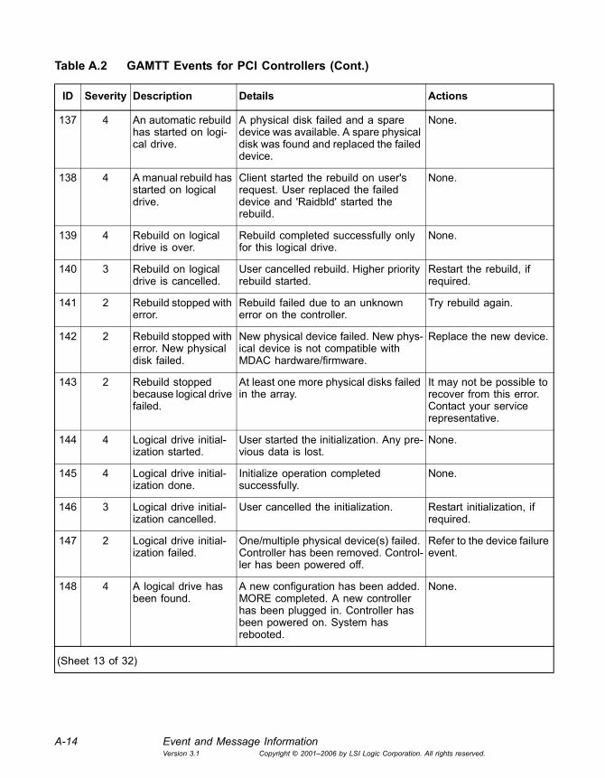
A-14 Event and Message InformationVersion 3.1 Copyright © 2001�2006 by LSI Logic Corporation. All rights reserved.
137 4 An automatic rebuild has started on logi-cal drive.
A physical disk failed and a spare device was available. A spare physical disk was found and replaced the failed device.
None.
138 4 A manual rebuild has started on logical drive.
Client started the rebuild on user's request. User replaced the failed device and 'Raidbld' started the rebuild.
None.
139 4 Rebuild on logical drive is over.
Rebuild completed successfully only for this logical drive.
None.
140 3 Rebuild on logical drive is cancelled.
User cancelled rebuild. Higher priority rebuild started.
Restart the rebuild, if required.
141 2 Rebuild stopped with error.
Rebuild failed due to an unknown error on the controller.
Try rebuild again.
142 2 Rebuild stopped with error. New physical disk failed.
New physical device failed. New phys-ical device is not compatible with MDAC hardware/firmware.
Replace the new device.
143 2 Rebuild stopped because logical drive failed.
At least one more physical disks failed in the array.
It may not be possible to recover from this error. Contact your service representative.
144 4 Logical drive initial-ization started.
User started the initialization. Any pre-vious data is lost.
None.
145 4 Logical drive initial-ization done.
Initialize operation completed successfully.
None.
146 3 Logical drive initial-ization cancelled.
User cancelled the initialization. Restart initialization, if required.
147 2 Logical drive initial-ization failed.
One/multiple physical device(s) failed. Controller has been removed. Control-ler has been powered off.
Refer to the device failure event.
148 4 A logical drive has been found.
A new configuration has been added. MORE completed. A new controller has been plugged in. Controller has been powered on. System has rebooted.
None.
Table A.2 GAMTT Events for PCI Controllers (Cont.)
ID Severity Description Details Actions
(Sheet 13 of 32)

GAMTT Events A-15Version 3.1 Copyright © 2001�2006 by LSI Logic Corporation. All rights reserved.
149 4 A logical drive has been deleted.
A new configuration has been added. A new logical device has been deleted. Controller has been removed. Controller has been powered off.
None.
150 4 Expand Capacity started.
User started the Online RAID Expan-sion operation.
None.
151 4 Expand Capacity completed.
Online RAID Expansion completed. None.
152 2 Expand Capacity stopped with error.
Multiple physical disks failed. It may not be possible to recover from this error. Contact your service representative.
153 0 Bad blocks found. Bad sector was found on a physical disk during consistency check/rebuild/RAID Expansion operation.
Run a Consistency Check with the Restore option. Restore data from a backup.
154 4 Logical drive size changed.
A new configuration has been added. RAID Expansion has added extra capacity.
None.
155 4 Logical drive type changed.
A new configuration has been added. RAID migration completed. RAID Expansion completed on RAID 1.
None.
156 1 Bad data blocks found. Possible data loss.
Bad blocks were found on multiple physical devices in same zone.
Restore data from a backup.
157 4 Logical drive LUN mapping has been written to config.
None. None
158 1 Attempt to read data from block that is marked in Bad Data Table.
Attempt to read from block that is already marked bad in Bad Data Table. Potential data loss.
Restore data from a backup.
Table A.2 GAMTT Events for PCI Controllers (Cont.)
ID Severity Description Details Actions
(Sheet 14 of 32)

A-16 Event and Message InformationVersion 3.1 Copyright © 2001�2006 by LSI Logic Corporation. All rights reserved.
159 2 Data for Disk Block has been lost due to logical drive problem.
Data retained in RAID cache for a write-back logical drive cannot be stored to the physical medium because of logical drive problem. Log-ical drive problem could be due to multiple physical media error, multiple physical devices offline, or other reasons.
Insure that all the physi-cal drives related to the logical drive, disk chan-nel, enclosure, or cabling are functional and acces-sible. Repair or replace them if necessary.
160 2 Temporary-Offline RAID5/RAID3 array is available to the user again with the possibility of data loss in the array.
Temporary-Offline state caused because of transient errors in physical drives.
Verify data from backup.
161 2 Temporary-Offline RAID0+1/RAID1/RAID0/JBOD array is available to the user again.
Temporary-Offline state caused because of transient errors in physical drives.
None.
162 4 A standby rebuild has started on a log-ical drive.
A physical disk failed and a spare device was available.
None.
163 2 Reconstruct detected uncorrect-able double medium errors.
None. None.
164 4 Reconstruction resumed.
None. None.
165 2 Reconstruction resume failed due to configuration mismatch.
None. None.
166 4 LD Properties updated.
None. None.
167 3 Marking LD inconsis-tent due to active writes at shutdown.
None. None.
Table A.2 GAMTT Events for PCI Controllers (Cont.)
ID Severity Description Details Actions
(Sheet 15 of 32)

GAMTT Events A-17Version 3.1 Copyright © 2001�2006 by LSI Logic Corporation. All rights reserved.
176 4 Logical drive back-ground initialization started.
User may have started background initialization. Firmware may have auto-matically started background initialization.
None.
177 4 Logical drive back-ground initialization stopped.
User may have stopped background initialization. Firmware may have auto-matically stopped background initialization.
None.
178 4 Logical drive back-ground initialization paused.
Background initialization paused due to higher priority operation.
None.
179 4 Logical drive back-ground initialization restarted.
Background initialization restarted after being paused.
None.
180 2 Logical drive back-ground initialization failed.
Background initialization failed. None.
181 4 Logical drive back-ground initialization completed.
Background initialization completed successfully.
None.
182 2 Low battery charge level. Logical drive may have lost data.
Controller was powered off for dura-tion longer than battery capacity. User connected a new controller. User con-nected a new BBU.
Run consistency check to verify logical drive consis-tency. If needed, restore data from backup.
183 2 Inconsistent data found during consis-tency check.
Logical drive is not initialized. One of the physical disks is failing.
Run consistency check with restoration flag on.
184 2 Cluster ownership changed.
Reserve/release action taken by the operating system.
None.
185 4 Unable to recover medium error during background initialization.
None None
256 1 Fan failure. Cable connection is broken. Fan failure. Replace fan.
257 4 Fan has been restored.
Faulty fan has been replaced. Cable is connected properly.
None.
Table A.2 GAMTT Events for PCI Controllers (Cont.)
ID Severity Description Details Actions
(Sheet 16 of 32)
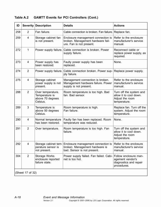
A-18 Event and Message InformationVersion 3.1 Copyright © 2001�2006 by LSI Logic Corporation. All rights reserved.
258 2 Fan failure. Cable connection is broken. Fan failure. Replace fan.
259 4 Storage cabinet fan is not present.
Enclosure management connection is broken. Management hardware fail-ure. Fan is not present.
Refer to the enclosure manufacturer's service manual.
272 1 Power supply failure. Cable connection is broken. Power supply failure.
Reconnect cable or replace power supply, as required.
273 4 Power supply has been restored.
Faulty power supply has been replaced.
None.
274 2 Power supply failure. Cable connection broken. Power sup-ply failure.
Replace power supply.
275 4 Storage cabinet power supply is not present.
Management connection is broken. Management hardware failure. Power supply is not present.
Refer to the enclosure manufacturer's service manual.
288 2 Over temperature. Temperature is above 70 degrees Celsius.
Room temperature is too high. Bad fan. Bad sensor.
Turn off the system and allow it to cool down. Adjust the room temperature.
289 3 Temperature is above 50 degrees Celsius.
Room temperature is high.Fan failure.
Replace fan. Turn off the system. Adjust the room temperature.
290 4 Normal temperature has been restored.
Faulty fan has been replaced. Room temperature was reduced.
None.
291 2 Over temperature. Room temperature is too high. Fan failure.
Turn off the system and allow it to cool down. Adjust the room temperature.
292 4 Storage cabinet tem-perature sensor is not present.
Enclosure management connection is broken. Management hardware is bad. Sensor is not present.
Refer to the enclosure manufacturer's service manual.
304 2 Storage Works enclosure reported failure state.
Power supply failed. Fan failed. Cabi-net is too hot.
Follow enclosure man-agement vendor's diagnostics and repair procedures.
Table A.2 GAMTT Events for PCI Controllers (Cont.)
ID Severity Description Details Actions
(Sheet 17 of 32)
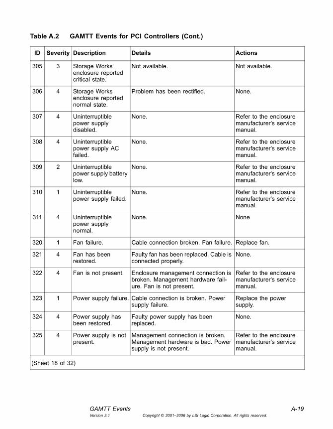
GAMTT Events A-19Version 3.1 Copyright © 2001�2006 by LSI Logic Corporation. All rights reserved.
305 3 Storage Works enclosure reported critical state.
Not available. Not available.
306 4 Storage Works enclosure reported normal state.
Problem has been rectified. None.
307 4 Uninterruptible power supply disabled.
None. Refer to the enclosure manufacturer's service manual.
308 4 Uninterruptible power supply AC failed.
None. Refer to the enclosure manufacturer's service manual.
309 2 Uninterruptible power supply battery low.
None. Refer to the enclosure manufacturer's service manual.
310 1 Uninterruptible power supply failed.
None. Refer to the enclosure manufacturer's service manual.
311 4 Uninterruptible power supply normal.
None. None
320 1 Fan failure. Cable connection broken. Fan failure. Replace fan.
321 4 Fan has been restored.
Faulty fan has been replaced. Cable is connected properly.
None.
322 4 Fan is not present. Enclosure management connection is broken. Management hardware fail-ure. Fan is not present.
Refer to the enclosure manufacturer's service manual.
323 1 Power supply failure. Cable connection is broken. Power supply failure.
Replace the power supply.
324 4 Power supply has been restored.
Faulty power supply has been replaced.
None.
325 4 Power supply is not present.
Management connection is broken. Management hardware is bad. Power supply is not present.
Refer to the enclosure manufacturer's service manual.
Table A.2 GAMTT Events for PCI Controllers (Cont.)
ID Severity Description Details Actions
(Sheet 18 of 32)
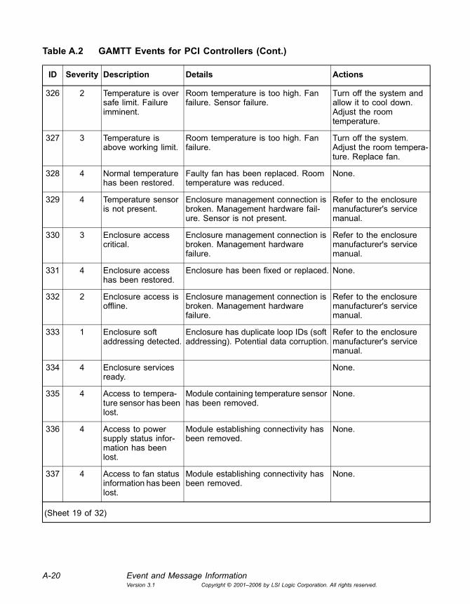
A-20 Event and Message InformationVersion 3.1 Copyright © 2001�2006 by LSI Logic Corporation. All rights reserved.
326 2 Temperature is over safe limit. Failure imminent.
Room temperature is too high. Fan failure. Sensor failure.
Turn off the system and allow it to cool down. Adjust the room temperature.
327 3 Temperature is above working limit.
Room temperature is too high. Fan failure.
Turn off the system. Adjust the room tempera-ture. Replace fan.
328 4 Normal temperature has been restored.
Faulty fan has been replaced. Room temperature was reduced.
None.
329 4 Temperature sensor is not present.
Enclosure management connection is broken. Management hardware fail-ure. Sensor is not present.
Refer to the enclosure manufacturer's service manual.
330 3 Enclosure access critical.
Enclosure management connection is broken. Management hardware failure.
Refer to the enclosure manufacturer's service manual.
331 4 Enclosure access has been restored.
Enclosure has been fixed or replaced. None.
332 2 Enclosure access is offline.
Enclosure management connection is broken. Management hardware failure.
Refer to the enclosure manufacturer's service manual.
333 1 Enclosure soft addressing detected.
Enclosure has duplicate loop IDs (soft addressing). Potential data corruption.
Refer to the enclosure manufacturer's service manual.
334 4 Enclosure services ready.
None.
335 4 Access to tempera-ture sensor has been lost.
Module containing temperature sensor has been removed.
None.
336 4 Access to power supply status infor-mation has been lost.
Module establishing connectivity has been removed.
None.
337 4 Access to fan status information has been lost.
Module establishing connectivity has been removed.
None.
Table A.2 GAMTT Events for PCI Controllers (Cont.)
ID Severity Description Details Actions
(Sheet 19 of 32)
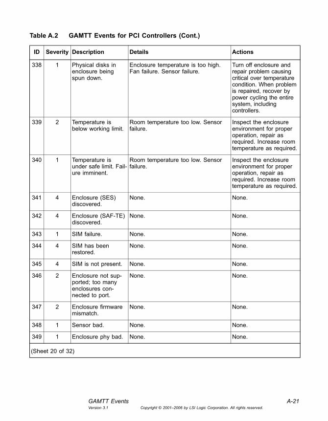
GAMTT Events A-21Version 3.1 Copyright © 2001�2006 by LSI Logic Corporation. All rights reserved.
338 1 Physical disks in enclosure being spun down.
Enclosure temperature is too high. Fan failure. Sensor failure.
Turn off enclosure and repair problem causing critical over temperature condition. When problem is repaired, recover by power cycling the entire system, including controllers.
339 2 Temperature is below working limit.
Room temperature too low. Sensor failure.
Inspect the enclosure environment for proper operation, repair as required. Increase room temperature as required.
340 1 Temperature is under safe limit. Fail-ure imminent.
Room temperature too low. Sensor failure.
Inspect the enclosure environment for proper operation, repair as required. Increase room temperature as required.
341 4 Enclosure (SES) discovered.
None. None.
342 4 Enclosure (SAF-TE) discovered.
None. None.
343 1 SIM failure. None. None.
344 4 SIM has been restored.
None. None.
345 4 SIM is not present. None. None.
346 2 Enclosure not sup-ported; too many enclosures con-nected to port.
None. None.
347 2 Enclosure firmware mismatch.
None. None.
348 1 Sensor bad. None. None.
349 1 Enclosure phy bad. None. None.
Table A.2 GAMTT Events for PCI Controllers (Cont.)
ID Severity Description Details Actions
(Sheet 20 of 32)
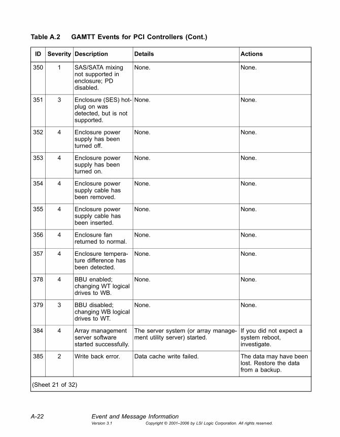
A-22 Event and Message InformationVersion 3.1 Copyright © 2001�2006 by LSI Logic Corporation. All rights reserved.
350 1 SAS/SATA mixing not supported in enclosure; PD disabled.
None. None.
351 3 Enclosure (SES) hot-plug on was detected, but is not supported.
None. None.
352 4 Enclosure power supply has been turned off.
None. None.
353 4 Enclosure power supply has been turned on.
None. None.
354 4 Enclosure power supply cable has been removed.
None. None.
355 4 Enclosure power supply cable has been inserted.
None. None.
356 4 Enclosure fan returned to normal.
None. None.
357 4 Enclosure tempera-ture difference has been detected.
None. None.
378 4 BBU enabled; changing WT logical drives to WB.
None. None.
379 3 BBU disabled; changing WB logical drives to WT.
None. None.
384 4 Array management server software started successfully.
The server system (or array manage-ment utility server) started.
If you did not expect a system reboot, investigate.
385 2 Write back error. Data cache write failed. The data may have been lost. Restore the data from a backup.
Table A.2 GAMTT Events for PCI Controllers (Cont.)
ID Severity Description Details Actions
(Sheet 21 of 32)

GAMTT Events A-23Version 3.1 Copyright © 2001�2006 by LSI Logic Corporation. All rights reserved.
386 3 Internal log struc-tures getting full, PLEASE SHUT-DOWN AND RESET THE SYSTEM IN THE NEAR FUTURE.
Too many configuration changes occurred since the last boot.
Reboot the system by power cycling when ever convenient.
388 0 Controller is dead. System is discon-necting from this controller.
Hardware failure. Contact your service representative.
389 3 Controller has been reset.
Controller received a reset command. If this was an unexpected event, refer to the enclo-sure manufacturer's service manual.
390 4 Controller is found. New controller has been installed.Management software has restarted.System has rebooted.
None.
391 0 Controller is gone. System is discon-necting from this controller.
Controller has been powered off or has been reset.Controller has been removed from the system.
None.
392 4 Battery present. A battery module has been detected and is now operational.
None.
393 3 Battery is bad. Battery cannot maintain charge. Replace the battery.
394 4 Battery power OK. Battery has enough power to enable the write data cache.
None.
395 0 Controller is gone. System is discon-necting from this controller.
The connection to the controller has been lost.
None.
396 4 Controller powered on.
Controller was removed from the sys-tem. Controller has been powered off.
None.
397 4 Controller is online. New controller has been installed. None.
Table A.2 GAMTT Events for PCI Controllers (Cont.)
ID Severity Description Details Actions
(Sheet 22 of 32)

A-24 Event and Message InformationVersion 3.1 Copyright © 2001�2006 by LSI Logic Corporation. All rights reserved.
398 0 Controller is gone. System is discon-necting from this controller.
Controller was set online. None.
399 3 Controller's partner is gone, controller is in failover mode now.
Controller was set offline. If you did not expect this, investigate.
400 4 Battery recondition-ing is started.
User started a battery reconditioning. None.
401 4 Battery recondition-ing is finished.
Battery reconditioning completed successfully.
None.
402 4 Battery recondition-ing is canceled.
User cancelled the battery reconditioning.
Restart the battery recon-ditioning, if required.
403 1 Installation aborted. Equipment improperly arranged while powered off.
Re-establish proper arrangement.
404 1 Controller firmware mismatch.
Replacement controller with downlevel firmware installed.
Reload controller firmware.
405 2 BBU removed. BBU physically removed. Reinstall the BBU.
406 1 WARM BOOT failed. Memory error detected during WARM boot scan. Possible data loss.
Restore data from a back up.
407 4 Battery calibration cycle started.
New battery detected. None.
408 4 Battery calibration cycle finished.
Battery calibration completed successfully.
None.
409 4 Battery calibration cycle was cancelled.
User cancelled the battery calibration cycle.
None.
410 2 Battery is not present.
The battery electronics are present but a battery was not detected.
Install or connect the battery.
411 4 Controller entered conservative cache mode.
User changed the setting. Controller preparing for shutdown. Battery low. RAID expansion in process. Over-temp condition. No redundant power. Power supply failure. UPS ac failed. UPS battery low.
If this was an unexpected event, refer to the enclo-sure manufacturer's service manual.
Table A.2 GAMTT Events for PCI Controllers (Cont.)
ID Severity Description Details Actions
(Sheet 23 of 32)

GAMTT Events A-25Version 3.1 Copyright © 2001�2006 by LSI Logic Corporation. All rights reserved.
412 4 Controller entered normal cache mode.
None. None.
413 4 Controller device start complete.
None. None.
414 3 Soft ECC error corrected.
Faulty memory module. Replace memory module.
415 3 Physical ECC error corrected.
Faulty memory module. Replace memory module.
416 4 Battery recondition suggested.
None. None.
417 3 Controller's partner has been removed.
None. None.
418 2 BBU out of service. BBU cannot power the cache if AC power fails. Firmware will switch WriteBack logical drives to WriteThrough.
Replace BBU.
419 4 Updated partner's status.
None. None.
420 4 Relinquished partner.
None. None.
421 3 Inserted partner. None. None.
422 4 Dual controllers enabled.
None. None.
423 2 Disabled partner. None. Refer to the enclosure manufacturer's service manual.
424 4 Dual controllers entered nexus.
None. None.
425 1 Controller boot ROM image needs to be reloaded.
Wrong firmware image file down-loaded. MAC address changed.
Contact your service rep-resentative to reload the boot ROM image.
426 1 Controller is using default non-unique world-wide name.
MAC address lost or not set. Contact your service rep-resentative to set the controller MAC address.
Table A.2 GAMTT Events for PCI Controllers (Cont.)
ID Severity Description Details Actions
(Sheet 24 of 32)

A-26 Event and Message InformationVersion 3.1 Copyright © 2001�2006 by LSI Logic Corporation. All rights reserved.
427 2 Mirror Race recovery failed.
Some physical devices may have failed.
Run consistency check and restore consistency.
428 0 Mirror Race on criti-cal logical drive.
Logical device is critical. Replace failed physical disk and rebuild.
429 4 Controller con-nected to cluster.
One or more controllers detected dur-ing scan and entered nexus with those controllers.
None.
430 4 Controller discon-nected from cluster.
All other controllers in cluster are inac-cessible due to controller powered off or controller failure or cable failure.
If this was an unexpected event, refer to service manual and correct the failure.
431 2 Controller improperly shut down! Data may have been lost.
User improperly shutdown the control-ler that resulted in inconsistent logical drive and/or data loss.
Run consistency check to verify logical drive consistency.If needed, restore data from backup.
432 4 Dual-active auto-matic flash of replacement controller.
Replacement controller is being flashed with survivor's firmware.
None.
433 2 Dual-active negotia-tion failed jumpers.
Jumper settings do not match. Replace, adjust or add components so that the controllers have the same jumper settings.
434 2 Dual-active negotia-tion failed IDs.
Controller IDs not unique. Both con-trollers have same ID.
Replace, adjust or add components so that the controllers have the cor-rect IDs.
435 2 Dual-active negotia-tion failed board types.
Board types differ. Both controllers must be of the same type.
Replace appropriate con-troller so that the board types are the same.
436 2 Dual-active negotia-tion failed disk channels.
Number of disk channels differ. Both controllers must have same number of disk channels.
Replace, adjust or add components so that the controllers have the same number of disk channels.
Table A.2 GAMTT Events for PCI Controllers (Cont.)
ID Severity Description Details Actions
(Sheet 25 of 32)

GAMTT Events A-27Version 3.1 Copyright © 2001�2006 by LSI Logic Corporation. All rights reserved.
437 2 Dual-active negotia-tion failed host ports.
Host ports differ. Both controllers must have same number of host ports.
Replace, adjust or add components so that the controllers have the same number of host ports.
438 2 Dual-active negotia-tion failed memory size.
Memory sizes differ. Both controllers must have same control store size.
Replace, adjust or add components so that the controllers have the same control store size.
439 2 Dual-active negotia-tion failed cache memory size.
Cache memory sizes differ. Both con-trollers must have same cache memory size.
Replace, adjust or add components so that the controllers have the same cache memory size.
440 1 Error in Mirror Race Table.
Logical drives appear in the mirror race table that don't exist in the con-figuration -- possible data integrity issue.
Check configuration for accuracy, run consis-tency check and restore consistency.
441 2 A replacement con-troller attempted to stop the surviving controller.
Incompatible replacement controller firmware or hardware.
Obtain a compatible replacement controller.
442 4 Patrol Read iteration completed.
None. None.
443 4 Controller entered 'Write Through' cache mode.
User changed the setting. Battery low. Over-temp condition.
None.
444 4 Controller entered 'Write Back' cache mode.
User changed the setting. Battery became normal.
None.
445 4 Update device state request sent from the peer controller.
Peer controller found state change. None
446 4 Data in cache flushed during power up.
None None
447 4 Data in cache not flushed during power up.
Configuration mismatch found. Check configuration. Restore the data from the backup.
Table A.2 GAMTT Events for PCI Controllers (Cont.)
ID Severity Description Details Actions
(Sheet 26 of 32)

A-28 Event and Message InformationVersion 3.1 Copyright © 2001�2006 by LSI Logic Corporation. All rights reserved.
448 4 Consistency Check rate changed.
None. None.
449 4 Background initial-ization rate changed.
None. None.
450 4 Flush rate changed. None. None.
451 4 Patrol Read Rate changed.
None. None.
452 4 Rebuild rate changed.
None. None.
453 4 Reconstruction rate changed.
None. None.
454 3 Cluster down; com-munication with peer lost.
None. None.
455 4 Alarm disabled by user.
None. None.
456 4 Alarm enabled by user.
None. None.
457 3 Unable to recover cache data due to configuration mismatch.
None. None.
458 4 Cache data recov-ered successfully.
None. None.
459 4 Controller cache dis-carded due to firmware version incompatibility.
None. None.
460 4 Factory defaults restored.
None. None.
461 4 Hibernate command received from host.
None. None.
462 4 Event log cleared. None. None.
463 4 Event log wrapped. None. None.
Table A.2 GAMTT Events for PCI Controllers (Cont.)
ID Severity Description Details Actions
(Sheet 27 of 32)

GAMTT Events A-29Version 3.1 Copyright © 2001�2006 by LSI Logic Corporation. All rights reserved.
464 3 Not enough control-ler memory.
None. None.
465 4 Patrol Read paused. None. None.
466 4 Patrol Read resumed.
None. None.
467 4 Patrol Read started. None. None.
468 4 Shutdown command received from host.
None. None.
469 4 User entered firm-ware debugger.
None. None.
470 2 Battery temperature is high.
None. None.
471 4 Battery is charging. None. None.
472 3 Battery is discharging.
None. None.
473 3 Battery needs to be replaced.
None. None.
474 2 Battery relearn timed out.
None. None.
475 4 Battery relearn pend-ing: Battery is under charge.
None. None.
476 4 Current capacity of the battery is below SOH/3.
None. None.
477 4 Current capacity of the battery is greater than SOH/3.
None. None.
480 4 Battery charge complete
None. None.
481 4 Battery Relearn request received.
None. None.
Table A.2 GAMTT Events for PCI Controllers (Cont.)
ID Severity Description Details Actions
(Sheet 28 of 32)

A-30 Event and Message InformationVersion 3.1 Copyright © 2001�2006 by LSI Logic Corporation. All rights reserved.
482 4 Controller Cache dis-carded by user.
None. None.
512 4 System started. The server system (or array manage-ment utility server) started.
If you did not expect a system reboot, investigate.
513 4 Size table full. Too much physical disk size informa-tion is defined.
Remove unused size information from this system.
514 4 User logged in. An array management utility user logged in on the server system.
Not available.
515 4 User logged out. An array management utility user logged out of the server system.
Not available.
516 4 Server alive. Reconnected to server. Server rebooted.
None.
517 2 Lost connection to server, or server is down.
Lost network connection to server. Server shut down.
None.
518 4 Automatic reboot count has changed.
Controller has rebooted. Automatic reboot has rearmed itself or was reconfigured.
None.
519 4 Battery test has started.
Battery test has started. None.
520 4 Battery test complete.
Battery test complete. See battery test status for completion mode.
521 4 Battery test canceled.
Battery test canceled. None.
522 2 Battery test failed - battery bad.
Battery test failed - battery bad. Replace battery.
640 3 Channel failed. Cable disconnected. Plug in cable.
641 3 Channel online. Cable reconnected. None.
642 1 Back end SCSI bus dead.
Lost access to data on SCSI bus. None.
643 4 Back end SCSI bus alive.
Regained access to data on SCSI bus.
None.
Table A.2 GAMTT Events for PCI Controllers (Cont.)
ID Severity Description Details Actions
(Sheet 29 of 32)
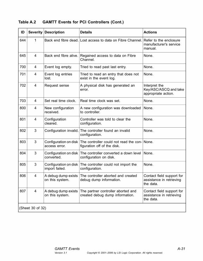
GAMTT Events A-31Version 3.1 Copyright © 2001�2006 by LSI Logic Corporation. All rights reserved.
644 1 Back end fibre dead. Lost access to data on Fibre Channel. Refer to the enclosure manufacturer's service manual.
645 4 Back end fibre alive. Regained access to data on Fibre Channel.
None.
700 4 Event log empty. Tried to read past last entry. None.
701 4 Event log entries lost.
Tried to read an entry that does not exist in the event log.
None.
702 4 Request sense A physical disk has generated an error.
Interpret the Key/ASC/ASCQ and take appropriate action.
703 4 Set real time clock. Real time clock was set. None.
800 4 New configuration received.
A new configuration was downloaded to controller.
None.
801 4 Configuration cleared.
Controller was told to clear the configuration.
None.
802 3 Configuration invalid. The controller found an invalid configuration.
None.
803 3 Configuration on disk access error.
The controller could not read the con-figuration off of the disk.
None.
804 3 Configuration on disk converted.
The controller converted a down level configuration on disk.
None.
805 3 Configuration on disk import failed.
The controller could not import the configuration.
None.
806 4 A debug dump exists on this system.
The controller aborted and created debug dump information.
Contact field support for assistance in retrieving the data.
807 4 A debug dump exists on this system.
The partner controller aborted and created debug dump information.
Contact field support for assistance in retrieving the data.
Table A.2 GAMTT Events for PCI Controllers (Cont.)
ID Severity Description Details Actions
(Sheet 30 of 32)

A-32 Event and Message InformationVersion 3.1 Copyright © 2001�2006 by LSI Logic Corporation. All rights reserved.
808 4 No valid Configura-tion On Disk (COD) found.
No physical disk contained a valid configuration on disk area. Physical disks were never written with COD. Physical disks were replaced while the controller system was offline.
Investigate if this is unexpected.
809 4 No valid SAN map found in Configura-tion On Disk (COD).
No physical disk contained a valid SAN map in its configuration on disk area. Physical disks may have been imported from a system that did not use SAN Mapping.
Investigate if this is unexpected.
810 4 MegaRAID firmware initialization started.
None. None.
811 3 Unable to recover cache data from TBBU.
None. None.
812 4 Cache data recov-ered from TBBU successfully.
None. None.
896 2 Internal controller hung.
Internal controller is in the hung state. Power controller off and on.
897 2 Internal controller firmware breakpoint.
Internal controller has encountered a firmware breakpoint.
Power controller off and on.
898 1 Firmware internal Exception condition.
Firmware encountered an Internal Exception condition.
Power controller off and on.
912 2 Internal controller i960 processor error.
Internal controller has encountered i960 processor specific error.
Power controller off and on.
928 2 Internal controller Strong-ARM proces-sor error.
Internal controller has encountered Strong-ARM processor specific error.
Power controller off and on.
944 1 Internal controller back-end hardware error.
Timeout waiting for Interrupt. Timeout waiting for command completion.
Power controller off and on.
960 2 SAS topology error: Loop detected.
None. None.
Table A.2 GAMTT Events for PCI Controllers (Cont.)
ID Severity Description Details Actions
(Sheet 31 of 32)

GAMTT Events A-33Version 3.1 Copyright © 2001�2006 by LSI Logic Corporation. All rights reserved.
961 2 SAS topology error: Unaddressable device.
None. None.
962 2 SAS topology error: Multiple ports to the same SAS address.
None. None.
963 2 SAS topology error: Expander error.
None. None.
964 2 SAS topology error: SMP timeout.
None. None.
965 2 SAS topology error: Out of route entries.
None. None.
966 2 SAS topology error: Index not found.
None. None.
967 2 SAS topology error: SMP function failed.
None. None.
968 2 SAS topology error: SMP CRC error.
None. None.
969 2 SAS topology error: Multiple subtractive.
None. None.
970 2 SAS topology error: Table to table.
None. None.
971 2 SAS topology error: Multiple paths.
None. None.
Table A.2 GAMTT Events for PCI Controllers (Cont.)
ID Severity Description Details Actions
(Sheet 32 of 32)

A-34 Event and Message InformationVersion 3.1 Copyright © 2001�2006 by LSI Logic Corporation. All rights reserved.
A.3 Spy Messages
Spy is a MegaRAID IDE application that is used with MegaRAID SATA Software RAID to monitor the status of physical drives, initiate rebuilds, and perform other related tasks. If you are using GAMTT Client with MegaRAID SATA Software RAID, you may see some of the messages listed in the following tables.
The Linux version of Spy logs messages to the System log and displays some error messages in the console. The Windows version of Spy logs messages to the NT Event Log. Depending on the Windows registry settings, messages can be logged to the System or to application folders.
Table A.3 Spy Log Messages
Message Severity Reason
MegaRAID IDE monitoring started. Info Spy daemon started.
MegaRAID IDE monitoring is shutting down. Info Spy daemon stopped.
No MegaRAID IDE adapter found. Error No controller found.
Error. Cannot allocate memory space. Error Not enough memory.
Logical Drive <logical drive id> is critical. Warning The specified logical drive is in critical state (this message is unused).
Logical Drive <logical drive id> is degraded. Warning The specified logical drive is in degraded state. One drive is inaccessible in RAID 1 logical drive. A maximum of one drive within each mirror is inaccessible, in the case of RAID 10. The logical drive can still be used.
Logical Drive <logical drive id> is Off-line. Warning The specified logical drive is off-line and cannot be used.
New media error found on controller <control-ler> channel <channel> drive <drive id>. Total number of errors for this drive is equal to <total error count>.
Warning New read/write error has occurred on a physical drive.
Rebuilding is started on <logical drive name>. Info A rebuild operation has been started on the specified logical drive.
(Sheet 1 of 3)

Spy Messages A-35Version 3.1 Copyright © 2001�2006 by LSI Logic Corporation. All rights reserved.
Consistency is started on <logical drive name>. Info A consistency check operation has been started on the specified logical drive.
Rebuilding. Source drive <drive id>, Target drive <drive id>.
Info A rebuild operation is in progress on the specified source and target drive.
Consistency. Source drive <drive id>, Target drive <drive id>
Info A consistency check operation is in progress on the specified source and tar-get drive.
Rebuilding stopped on <logical drive name>. Info The user stopped the rebuilding operation on the specified logical drive.
Consistency stopped on <logical drive name>. Info The user stopped the consistency check operation on the specified logical drive.
Rebuilding aborted on <logical drive name> Info The rebuilding operation has been aborted on the specified logical drive.
Consistency aborted on <logical drive name> Info The consistency check operation has been aborted on the specified logical drive.
Rebuilding completed successfully on <logical drive name>.
Info The rebuild operation has been com-pleted successfully on the specified logical drive.
Consistency completed successfully on <logical drive name>.
Info The consistency check operation has been completed successfully on the specified logical drive.
Rebuilding completed with <error count> errors on <logical drive name>.
Error The rebuilding operation has been com-pleted with errors on the specified logical drive.
Consistency completed with <error count> errors and <mismatch count> mismatches (uncorrected) on <logical drive name>
Error The consistency check operation has been completed with errors and mis-matches (uncorrected) on the specified array.
Consistency completed with <error count> errors and <mismatch count> mismatches (cor-rected) on <logical drive>
Error The consistency check operation has been completed with errors and mis-matches (corrected) on the specified array.
Too many errors encountered to proceed with consistency. Consistency stopped.
Info Consistency check stopped due to error threshold reached. (Not posted in NT event log.)
Table A.3 Spy Log Messages (Cont.)
Message Severity Reason
(Sheet 2 of 3)

A-36 Event and Message InformationVersion 3.1 Copyright © 2001�2006 by LSI Logic Corporation. All rights reserved.
Driver is not loaded. Error Could not locate driver. (Not posted in NT event log.)
Error in own process id creation. Error Could not create its own process ID. (Not posted in NT event log.)
Error in recreate database. Exiting Spy. Error Could not create its internal repository. (Not posted in NT event log.)
Internal error #n Error Internal error #n occurred (not posted in NT Event Log), where n = 2, 3, or 5 2: When call GetPhysicalDrive fails (in Linux)3: When call GetPhysicalDrive Fails (in Novell)5: When CC or rebuilding is going on and the driver indicates a progress percent-age of more than 100Note: These messages are provided to help trace possible Spy errors.
Physical drive '<drive name>� reached error threshold <threshold limit>.
Warning The named physical drive reached the error threshold limit. (Not posted in NT event log.)
Physical drive <drive name> status: Failed Error The specified physical drive status is �Fail�. (Not posted in NT event log.)
New SMART error found on controller <control-ler> channel <channel> drive <drive id>
Warning New SMART error is found on specified drive.
Logical Drive <drive no.> is optimal Info The logical drive status changed to optimal.
New configuration. <Configuration detail> Info A new configuration has been written.
Add Configuration<Configuration detail> Info A configuration has been added to an existing configuration.
Configuration cleared Info A configuration has been cleared.
Logical Drive <Drive id> is deleted Warning A logical drive has been deleted.
Physical Drive <Drive id> is removed Warning A physical drive has been removed.
Physical Drive <Drive id> is inserted Warning A physical drive has been inserted.
Table A.3 Spy Log Messages (Cont.)
Message Severity Reason
(Sheet 3 of 3)
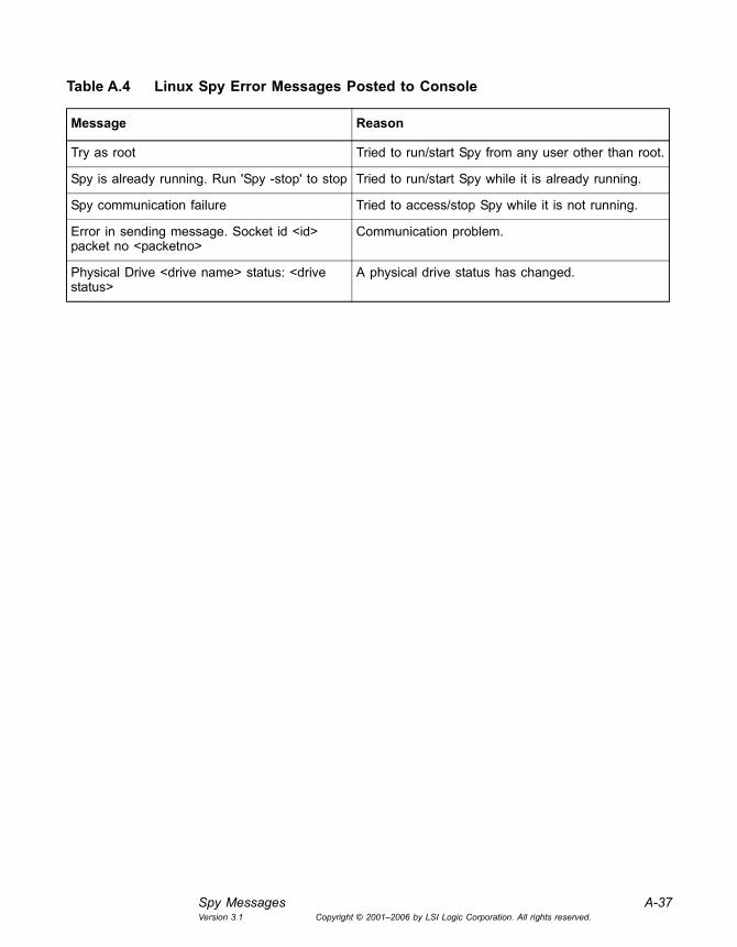
Spy Messages A-37Version 3.1 Copyright © 2001�2006 by LSI Logic Corporation. All rights reserved.
Table A.4 Linux Spy Error Messages Posted to Console
Message Reason
Try as root Tried to run/start Spy from any user other than root.
Spy is already running. Run 'Spy -stop' to stop Tried to run/start Spy while it is already running.
Spy communication failure Tried to access/stop Spy while it is not running.
Error in sending message. Socket id <id> packet no <packetno>
Communication problem.
Physical Drive <drive name> status: <drive status>
A physical drive status has changed.

A-38 Event and Message InformationVersion 3.1 Copyright © 2001�2006 by LSI Logic Corporation. All rights reserved.

Global Array Manager Transition Tool Client Software User�s Guide 1Version 3.1 Copyright © 2001�2006 by LSI Logic Corporation. All rights reserved.
Glossary
Application Program
A program designed to perform a specific function directly for the user, or for another application program. Examples of application programs include word processors, database programs, Web browsers, and communication programs.
Array Multiple disk drives configured to behave as a single, independent disk drive.
Automatic Rebuild
LSI Logic/Mylex controllers provide automatic rebuild capabilities in the event of a physical disk drive failure. The controller performs a rebuild operation automatically when a disk drive fails and both of the following conditions are true:
• A hot spare disk drive of identical or larger size is found attached to the same controller;
• All system drives that are dependent on the failed disk drive are configured as a redundant array: RAID 1, RAID 3, RAID 5, or RAID 10.
During the automatic rebuild process, system activity continues; however, system performance may degrade slightly.
Background Initialization
A technique in which the initialization of a disk array takes place in the background, allowing the array to be used immediately. The opposite is foreground initialization, which requires the array initialization to be complete before data can be written to it.
BIOS Basic Input/Output System, software that determines what a computer can do without accessing programs. The BIOS contains all the code required to control the keyboard, screen, drives, serial communications, and other functions. Usually the BIOS is built into a ROM chip installed on the motherboard so that the BIOS is always available and is not
2 GlossaryVersion 3.1 Copyright © 2001�2006 by LSI Logic Corporation. All rights reserved.
affected by disk failure. Sometimes the BIOS is recorded on a flash memory chip.
Cache A temporary storage area for frequently accessed or recently accessed data. Cache is used to speed up data transfer to and from a disk. See also Caching.
Cache Line Size The size of the data �chunk� that is read or written at one time. Cache Line Size is set in conjunction with stripe size. In the RAID Assist utility, the cache line size (also known as Segment Size) should be based on the stripe size you selected. The default segment size for LSI Logic/Mylex RAID controllers is 8K. See also Stripe Size.
Caching A process that allows data to be stored in a pre-designated area of a disk or RAM. Caching speeds up the operation of RAID systems, disk drives, computers, and servers. See also Cache.
Consistency Check
A process that verifies the integrity of redundant data. A consistency check on a RAID 1 or RAID 10 configuration checks to determine if the data on drives and their mirrored pair are exactly the same. For RAID Level 3 or RAID Level 5, a consistency check calculates the parity from the data written on the disk and compares it to the written parity. In the Global Array Manager and RAID Assist programs, you can run a consistency check that reports consistency errors and, optionally, fixes them, See also Parity Check.
Critical State A Logical Drive is in a �critical� state if it has been configured at RAID level 1, 3, 5, or 10, and one (and only one) of its drives is not �online.� The logical drive is considered �critical� data could be lost if another of its drives fails.
Note: I/O operation can only be performed with system drives that are online or critical.
Data Transfer Rate
The amount of data per unit of time moved through a channel or I/O bus in the course of execution of an I/O load, usually expressed in Mbytes/s.
Degraded Mode A RAID mode used when a component drive has failed.
Device Driver A software program that controls a particular type of device attached to a computer, such as a RAID subsystem or a disk drive.
Disk Failure Detection
The process a RAID controller uses to automatically detect SCSI disk failures. A monitoring process running on the controller checks, among

Glossary 3Version 3.1 Copyright © 2001�2006 by LSI Logic Corporation. All rights reserved.
other things, elapsed time on all commands issued to disks. A time-out causes the disk to be �reset� and the command to be retried. If the command times out again, the controller could take the disk �offline.� Some controllers also monitor SCSI bus parity errors and other potential problems. Any disk with too many errors is also taken �offline.� See also Offline.
Disk Media Error Management
A process by which a controllers transparently manages disk media errors. Disks are programmed to report errors, even ECC-recoverable errors. If ECC RAM is installed, the controller will correct ECC errors. When a disk reports a media error during a read, the controller reads the data from the mirror (RAID 1 or 10), or computes the data from the other blocks (RAID 3, RAID 5), and writes the data back to the disk that encountered the error. When a disk reports a media error during a write, the controller issues a �reassign� command to the disk, then writes the data out to a new location on the disk. Since the problem has been resolved, no error is reported to the system.
Drive Groups, Drive Packs
A group of individual disk drives (preferably identical) that are logically tied to each other and are addressed as a single unit. In some cases this may be called a drive �pack� when referring to just the physical devices.
All the physical devices in a drive group should have the same size; otherwise, each of the disks in the group effectively has the capacity of the smallest member. The total size of the drive group is the size of the smallest disk in the group multiplied by the number of disks in the group. For example, if you have four disks of 400 Mbytes each and one disk of 200 Mbytes in a pack, the effective capacity available for use is only 1000 Mbytes (5x200), not 1800 Mbytes.
ECC Error Correcting Code. A method of generating redundant information that can be used to detect and correct errors in stored or transmitted data.
eXtremeRAID The eXtremeRAID 2000 Ultra160 RAID controller features up to 64MB SDRAM ECC cache memory and can connect up to 60 drives for peak storage capacity of 4.32TB. Each of its four Ultra 160 SCSI LVD channels can transfer up to 160MB/s. Ideal for midrange and high-end servers, the eXtremeRAID 2000 delivers more than 8000 IOPs and sustained data transfer rates of greater than 200MB/s.

4 GlossaryVersion 3.1 Copyright © 2001�2006 by LSI Logic Corporation. All rights reserved.
Fault Tolerance The ability of a system to continue to perform its function even when one of its components has failed. A fault tolerant system requires redundancy in disk drives, power supplies, adapters, controllers, and cabling. LSI Logic/Mylex RAID controllers offer high levels of fault tolerance.
Flash ROM Memory on an adapter containing software that can be reprogrammed without removing it from the board.
Gigabit 109 (1,000,000,000) bits. Abbreviated as Gbit.
Gigabyte 230 (1,073,741,824) bytes. Abbreviated as Gbyte.
Global Array Manager (GAM)
An LSI Logic/Mylex RAID management utility that allows a system administrator to configure, monitor, and manage network RAID storage from anywhere in the world. GAM can communicate critical information via e-mail, fax, pager, SNMP, or the launching of an application.
IME See Integrated Mirroring Enhanced
Immediate RAID Availability
See Background Initialization
Integrated Mirroring Enhanced (IME)
A fault tolerant RAID configuration in which data on one �primary� disk is mirrored to up to four other disks. Each �mirrored stripe� is written to a disk and is mirrored to an �adjacent� disk. This is commonly referred to as RAID 1E.
I/O Input/Output. The transmission of information between an external source and the computer.
Kilobyte 210 (1,024) bytes. Abbreviated as Kbyte.
LAN Local Area Network. A network of interconnected workstations sharing the resources of a single processor or server, typically within the area of a small office building.
Logical Drive The logical devices presented to the operating system. The operating system handles the logical drive as if it were a single disk drive, although the drive may actually use storage space on several physical disk drives. See also Storage Device.
Logical Drive States
A logical (system) drive can be in the Online, Critical, or Offline state. (The term �online� is used for both physical and logical drives.)
Glossary 5Version 3.1 Copyright © 2001�2006 by LSI Logic Corporation. All rights reserved.
Megabit A million bits. Abbreviated as Mbit. Megabits per second (Mbits/s) is a common measure of the bandwidth of a transmission medium.
Megabyte 220 (1,048,576) bytes. Abbreviated as Mbyte.
MegaRAID Ultra320
A line of LSI Logic 1-, 2-, and 4-channel RAID storage adapters with Ultra320 support. Through support for 64-bit addressing, a robust RAID feature set, and advanced memory, and caching policies, LSI Logic Ultra320 MegaRAID solutions deliver enterprise-class data throughput, fault tolerant capabilities, and easy-to-use management utilities.
Mirroring The complete duplication of data on one disk drive to another disk drive. This duplication occurs simultaneously with each write operation: each disk is the mirror image of the other (also known as RAID Level 1, see RAID Levels). All LSI Logic/Mylex RAID controllers support mirroring.
MORE� Mylex Online RAID Expansion. An advanced configuration mode that allows expansion of any unconfigured or hot spare drive into the expandable drive group while the controller is online with the host. For example, a system using a five-disk-drive RAID set can add another disk drive to create a six-disk-drive RAID set. The MORE operation can be performed on all RAID levels except JBOD.
Global Array Manager (GAM) supports two MORE features:
• Expand Capacity allows logical drive expansion for FFx external controllers only.
• Expand Array allows array expansion for both PCI and FFx external controllers.
During the RAID set expansion process, which includes re-striping data from the old RAID set to the new RAID set, the controller continues to service host I/O requests.
NVRAM Non-Volatile Random Access Memory. A memory unit equipped with a battery so that the data stays intact even after the main power had been switched off.
Offline A Logical Drive is in an �offline� state if no data can be read from it or written to it. Offline does not apply to physical disk drives. System commands issued to offline logical drives are returned with an error status; no operations can be performed on offline logical drives. See also Logical Drive States, and Critical State.
6 GlossaryVersion 3.1 Copyright © 2001�2006 by LSI Logic Corporation. All rights reserved.
Parity A method of providing complete data redundancy while requiring only a fraction of the storage capacity of mirroring. The data and parity blocks are divided between the disk drives in such a way that if any single disk drive is removed or fails, the data on it can be reconstructed using the data on the remaining disk drives. The parity data may exist on only one disk drive or be distributed between all disk drives in a RAID group. See also Rotated XOR Redundancy.
Parity Check A function used to verify the integrity of data on a system drive. It verifies that mirror or parity information matches the stored data on the redundant arrays. If the parity block information is inconsistent with the data blocks, the controller corrects the inconsistencies. See also Consistency Check.
Partitioning A technology that allows the full usable storage capacity of a disk or array of disks to appear to an operating environment in the form of several virtual disks whose entire capacity approximates that of the underlying disk or array.
PROM Programmable Read-Only Memory. Memory that can be reprogrammed.
Protocol A special set of rules for transmitting data between two devices in a telecommunication connection.
Queue A line of commands or data waiting to be handled, usually in sequential order starting at the beginning of the line or sequence.
RAID Redundant Array of Independent Disks. A collection of two or more disks working together in an array. LSI Logic/Mylex RAID controllers implement this technology to connect up to 15 disk drives per channel. The different forms of RAID implementation are known as �RAID levels.� See also RAID Levels.
The system manager or integrator selects the appropriate RAID level for a system. This decision is based on which of the following are to be emphasized:
• Disk Capacity
• Data Availability (redundancy or fault tolerance)
• Disk Performance
RAID Assist A Mylex RAID management utility for configuration and maintenance of RAID controllers.

Glossary 7Version 3.1 Copyright © 2001�2006 by LSI Logic Corporation. All rights reserved.
RAID Levels The various RAID levels use different techniques to combine multiple disk drives into a single virtual unit. Each RAID level provides a different balance between performance, redundancy, and cost. Logic/Mylex disk array controllers support the following RAID levels:
RAID 0: Provides block �striping� across multiple drives, yielding higher performance than is possible with individual drives. RAID 0 does not provide any redundancy.
RAID 1: Drives are paired and mirrored. All data is 100 percent duplicated on a a second drive of equivalent size.
RAID 1E: Same as RAID 1, except that the data from the primary disk is mirrored on multiple disks.
RAID 3: Data is striped across three or more physical drives. Parity information, which is used to recover lost data, is stored on separate dedicated drives.
RAID 5: Data is striped across three or more physical drives. Parity information, which is used to recover lost data, is interspersed with user data.
RAID 10: Combines RAID 0 striping and RAID 1 mirroring. This level provides redundancy through mirroring.
JBOD: Sometimes referred to as �Just a Bunch of Drives.� Each drive is operated independently like a normal disk controller, or drives may be spanned and seen as a single drive. This level does not provide data redundancy.
RAID Migration A feature in RAID subsystems that allows a RAID level to be changed to another level without powering down the system.
RAM Random Access Memory. The �built-in� readable and writable data storage that comes with (or can be added to) a computer.
Read-Ahead Cache
A caching strategy whereby the computer anticipates data and holds it in cache until requested.
Recovery The process of reconstructing data from a failed disk using data from other disks in a fault tolerant array.
8 GlossaryVersion 3.1 Copyright © 2001�2006 by LSI Logic Corporation. All rights reserved.
ROM Read-Only Memory. Built-in computer memory containing data that normally can only be read, not written to. ROM contains the programming that allows a computer to be �booted up� when it is powered on. Unlike a computer's Random Access Memory (RAM), the data in ROM is not lost when the computer power is turned off. The ROM is sustained by a small long-life battery in your computer.
Rotated XOR Redundancy
XOR refers to the Boolean �Exclusive-OR� operator. Also known as Parity, a method of providing complete data redundancy while requiring only a fraction of the storage capacity of mirroring. In a system configured under RAID 3 or RAID 5 (which require at least three drives), all data and parity blocks are divided amongst the drives in such a way that if any single drive is removed (or fails), the data on it can be reconstructed using the data on the remaining drives. In any RAID 3 or RAID 5 array, the capacity allocated to redundancy is the equivalent of one drive.
RTC Real-Time Clock. A clock that keeps track of the time with its own power supply.
SAF-TE SCSI Accessed Fault-Tolerant Enclosure. An �open� specification that provides a comprehensive standardized method to monitor and report status information on the condition of disk drives, power supplies, and cooling systems used in high availability LAN servers and storage subsystems. The specification is independent of hardware I/O cabling, operating systems, server platforms, and RAID implementation because the enclosure itself is treated as simply another device on the SCSI bus. Products compliant with the SAF-TE specification reduce the cost of managing storage enclosures, making it easier for a LAN administrator to obtain base-level fault-tolerant alert notification and status information. All Mylex RAID controllers feature SAF-TE.
SAS See Serial Attached SCSI.
SATA Serial ATA is a point-to-point interface used to connect storage devices such as hard disks and CD-RW drives to the PC motherboard. The Serial ATA bus is a high-speed, internal bus that provides a low pin count, low-voltage-level bus for device connections between a host adapter and a Serial ATA device.
Glossary 9Version 3.1 Copyright © 2001�2006 by LSI Logic Corporation. All rights reserved.
SDRAM Synchronous Dynamic Random Access Memory. A form of dynamic random access memory (DRAM) that can be coordinated or synchronized to the clock speed of the computer.
Sector The unit in which data is physically stored and protected against errors on a fixed-block architecture disk.
Segment Size See Cache Line Size
Sequential I/O A type of read and write operation in which entire blocks of data are accessed one after another in sequence, as opposed to randomly.
Serial Attached SCSI
Serial Attached SCSI (SAS) is a point-to-point, full-duplex, dual-port interface that supports transmission of SCSI protocols over SATA-compatible cables and connectors.
Server A computer program that provides and manages services to other computer programs on the same or other computers. The computer that a server program runs on is also frequently referred to as a server.
Session The period of time between any two consecutive system shutdowns; system shutdown may be either a power off/on, or a hardware reset.
SMART Self-Monitoring Analysis and Reporting Technology. The industry standard reliability prediction indicator for both ATA/IDE and SCSI hard disk drives. Hard disk drives with SMART offer early warning of some hard disk failures so that critical data can be protected.
SNMP Simple Network Management Protocol. The protocol governing network management: for monitoring network devices and their functions.
Spanning A process that provides the ability to configure multiple drive packs or parts of multiple drive packs. In effect, spanning allows the volume used for data processing to be larger than a single drive. Spanning increases I/O speeds. However, the probability of drive failure increases as more drives are added to a drive pack. Spanned drive packs use striping for data processing. See also Striping and Drive Groups, Drive Packs.
Stripe Order The order in which SCSI disk drives appear within a drive group. This order must be maintained, and it is critical to the controller�s ability to �rebuild� failed drives.

10 GlossaryVersion 3.1 Copyright © 2001�2006 by LSI Logic Corporation. All rights reserved.
Stripe Size The size, in Kbytes (1024 bytes) of a single I/O operation. A stripe of data (data residing in actual physical disk sectors, which are logically ordered first to last) is divided over all disks in the drive group.
Stripe Width The number of striped SCSI drives within a drive group.
Striping The storing of a sequential block of incoming data across multiple SCSI drives in a group. For example, if there are three SCSI drives in a group, the data is separated into blocks. Block 1 of the data is stored on SCSI drive 1, block 2 on SCSI drive 2, block 3 on SCSI drive 3, block 4 on SCSI drive 1, block 5 on SCSI drive 2, and so on. This storage method increases the disk system throughput by ensuring a balanced load among all drives.
System Disk The disk on which a system�s operating software is stored.
System Drives See Logical Drives
TCP/IP Transmission Control Protocol/Internet Protocol. The basic communication language, or protocol, of the Internet. It can also be used as a communications protocol in intranets and extranets. When set up with direct access to the Internet, a computer is provided with a copy of the TCP/IP program just as every other computer that you may send messages to or get information from also has a copy of TCP/IP.
Terabyte A measure of memory capacity, 240 bytes; or roughly a thousand billion bytes (that is, a thousand gigabytes).
Throughput The number of I/O requests satisfied per unit of time (usually per second).
Tpm-C A benchmark, created by the Transaction Processing Performance Council (TPC), that reflects price and performance metrics. The TPC is a standards organization that measures transaction throughput of systems.
Transfer Rate The rate at which data moves between the host computer and storage, input, or output devices, usually expressed as a number of characters per second.
Write-Back Cache
A caching strategy in which write operations result in a completion signal being sent to the host operating system as soon as the cache (not the disk drive) receives the data to be written. The target disk drive will receive the data at a more appropriate time in order to increase controller
Glossary 11Version 3.1 Copyright © 2001�2006 by LSI Logic Corporation. All rights reserved.
performance. An optional cache battery backup can be used to protect against data loss as a result of a power failure or system crash.
Write-Through Cache
A caching strategy in which data is written to the SCSI drive before a completion status is returned to the host operating system. This caching strategy is considered more secure, since a power failure is less likely to cause loss of data. However, a write through cache results in slightly lower performance.
XOR Exclusive �Or�. A computer language function that generates parity in RAID systems; �this or that but not both.�

12 GlossaryVersion 3.1 Copyright © 2001�2006 by LSI Logic Corporation. All rights reserved.

Global Array Manager Transition Tool Client Software User�s GuideVersion 3.1 Copyright © 2001�2006 by LSI Logic Corporation. All rights reserved.
Customer Feedback
We would appreciate your feedback on this document. Please copy the following page, add your comments, and fax it to us at the number shown.
If appropriate, please also fax copies of any marked-up pages from this document.
Important: Please include your name, phone number, fax number, and company address so that we may contact you directly for clarification or additional information.
Thank you for your help in improving the quality of our documents.

Reader�s CommentsFax your comments to: LSI Logic Corporation
Technical PublicationsM/S AF-198Fax: 408.433.4333
Please tell us how you rate this document: Global Array Manager Transition Tool Client Software User�s Guide. Place a check mark in the appropriate blank for each category.
What could we do to improve this document?
If you found errors in this document, please specify the error and page number. If appropriate, please fax a marked-up copy of the page(s).
Please complete the information below so that we may contact you directly for clarification or additional information.
Excellent Good Average Fair PoorCompleteness of information ____ ____ ____ ____ ____Clarity of information ____ ____ ____ ____ ____Ease of finding information ____ ____ ____ ____ ____Technical content ____ ____ ____ ____ ____Usefulness of examples and
illustrations____ ____ ____ ____ ____
Overall manual ____ ____ ____ ____ ____
Name DateTelephoneTitle
Company NameStreetCity, State, Zip
Department Mail Stop
Fax

Information on this document On April 1, 2009, Fujitsu became the sole owner of Fujitsu Siemens Compu-ters. This new subsidiary of Fujitsu has been renamed Fujitsu Technology So-lutions.
This document from the document archive refers to a product version which was released a considerable time ago or which is no longer marketed.
Please note that all company references and copyrights in this document have been legally transferred to Fujitsu Technology Solutions.
Contact and support addresses will now be offered by Fujitsu Technology So-lutions and have the format …@ts.fujitsu.com.
The Internet pages of Fujitsu Technology Solutions are available at http://ts.fujitsu.com/... and the user documentation at http://manuals.ts.fujitsu.com.
Copyright Fujitsu Technology Solutions, 2009
Hinweise zum vorliegenden Dokument Zum 1. April 2009 ist Fujitsu Siemens Computers in den alleinigen Besitz von Fujitsu übergegangen. Diese neue Tochtergesellschaft von Fujitsu trägt seit-dem den Namen Fujitsu Technology Solutions.
Das vorliegende Dokument aus dem Dokumentenarchiv bezieht sich auf eine bereits vor längerer Zeit freigegebene oder nicht mehr im Vertrieb befindliche Produktversion.
Bitte beachten Sie, dass alle Firmenbezüge und Copyrights im vorliegenden Dokument rechtlich auf Fujitsu Technology Solutions übergegangen sind.
Kontakt- und Supportadressen werden nun von Fujitsu Technology Solutions angeboten und haben die Form …@ts.fujitsu.com.
Die Internetseiten von Fujitsu Technology Solutions finden Sie unter http://de.ts.fujitsu.com/..., und unter http://manuals.ts.fujitsu.com finden Sie die Benutzerdokumentation.
Copyright Fujitsu Technology Solutions, 2009


![[Array, Array, Array, Array, Array, Array, Array, Array, Array, Array, Array, Array]](https://static.documents.pub/doc/80x56/56816460550346895dd63b8b/array-array-array-array-array-array-array-array-array-array-array.jpg)


