18
Global TD-LTE Initiative (GTI) Estimation and Validation of TD-LTE coverage Network Planning Task Force Tokyo, 25 th -26 th on Apr 2012
Global TD-LTE Initiative (GTI)
Estimation and Validation of TD-LTE coverage
Network Planning Task Force
Tokyo, 25th -26th on Apr 2012

TF Scope
•Conclusion review in 2011•Frequency Reuse 1 has better SE and final THR, less sensitive to burst increasing system load with the maturity of the network infrastructures•TD-LTE network can flexibly adapt its DL/UL resource partition to meet requirements of different traffic models
•Objective in 2012•How to do coverage planning of LTE?•Estimation of TD‐LTE coverage•TD‐LTE trial results sharing•What are the solutions for problems we faced in coverage?

Influence factors of coverage‐ Survey Results
2012
TBD
• Scenario ,frequency band and antenna configuration are all important factors which should be paid more attention
• Different scenario, different shadow fading margin
• Different frequency band, different penetration loss and antenna gain
• Different antenna configuration, different antenna gain
operatorscenario and percentage
Dense urban Urban Suburban Rural Mountain area Sea area road
Belltel 2% 53% 26% 13% 50% of Philippines 7%CMCC 19% 49% 32%
FarEstone 2% 9% 9% 79%Iburst 5% 40% 25% 25% 5%
Tatung 2% 2% 18% 23% 55%Nextwave 2% 3% 85% 10%Omantel 5% 15% 30% 30% 5% 15%
38 2570 MHz – 2620 MHz39 1880 MHz – 1920 MHz40 2300 MHz – 2400 MHz41 2496 MHz – 2690 MHz

Link Budget
With the same frequency band(38) and scenario(dense urban), antenna gain and receive diversity gain are the causes of path loss and limiting channel difference
• Antenna configuration:•PDCCH coverage depends on antenna gain: 2 path>4 path>8 path•PRACH coverage depends on receive diversity gain and antenna gain: 8 path>4 path>2 path•Limiting control channel coverage: 4 path>8 path>2path
• Comparison between TDD and FDD:•control channel of TD-LTE(2 path) & LTE FDD(2 path) has the same coverage

Trial Results‐2/8 path antenna
Condition• Test environment: urban, /dense urban,• Network Configuration: band 38 , 20MHz bandwidth, frequency reuse factor=1, 3 sectors/cell• Antenna configuration: 2 path(17.5~18dBi),8 path(16~16.5dBi)• Test method: test UE(always locked in the serving cell PCI) goes straight along the antenna
normal direction
~BSh = 30 40m,ISD = 500m ~BSh = 20 30m,ISD = 300m
downlink uplink Random accessResults
8 path
2 path
8 path
2 path
8 path
2 path
Vendor A0 50% 70% 0 50% 70%
Vendor A Vendor B C Vendor D Vendor B Vendor DVendor C0 50% 70%0 50% 70% 0 50% 70% 0 50% 70% 0 50% 70% 0 70% 0 50% 70% 0 50% 70% 0 50% 70%
Conclusion• With same type of antenna, the coverage of UL¥DL (call drop point)is close to each other; the
coverage of random access point is nearer than them• From call drop point of view, Compared to 2 antenna, DL coverage gain of 8 antenna is 13.21%,UL
coverage gain of 8 antenna is 20.71%(coverage gain=(D8-D2)/D2)• From edge data rate at 5Mbps point of view, Compared to 2 antenna, DL coverage gain of 8
antenna is 39%,UL coverage gain of 8 antenna is 44.56%
Trial results‐
penetration loss
Condition
Results
Conclusion
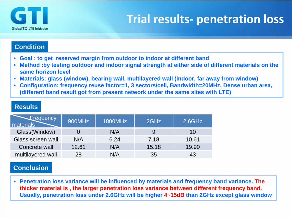
• Goal : to get reserved margin from outdoor to indoor at different band • Method :by testing outdoor and indoor signal strength at either side of different materials on the
same horizon level• Materials: glass (window), bearing wall, multilayered wall (indoor, far away from window)• Configuration: frequency reuse factor=1, 3 sectors/cell, Bandwidth=20MHz, Dense urban area,
(different band result got from present network under the same sites with LTE)
• Penetration loss variance will be influenced by materials and frequency band variance. The thicker material is , the larger penetration loss variance between different frequency band. Usually, penetration loss under 2.6GHz will be higher 4~15dB than 2GHz except glass window
Frequency materials 900MHz 1800MHz 2GHz 2.6GHz
Glass(Window) 0 N/A 9 10Glass screen wall N/A 6.24 7.18 10.61
Concrete wall 12.61 N/A 15.18 19.90 multilayered wall 28 N/A 35 43
Summary
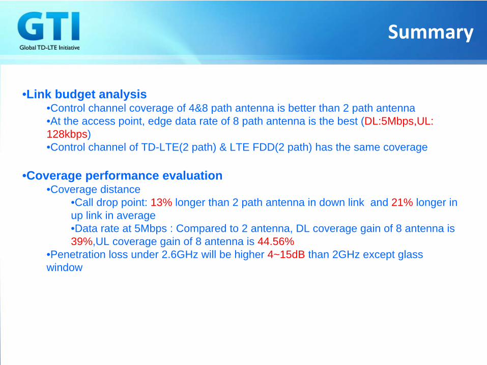
•Link budget analysis•Control channel coverage of 4&8 path antenna is better than 2 path antenna•At the access point, edge data rate of 8 path antenna is the best (DL:5Mbps,UL: 128kbps)•Control channel of TD-LTE(2 path) & LTE FDD(2 path) has the same coverage
•Coverage performance evaluation•Coverage distance
•Call drop point: 13% longer than 2 path antenna in down link and 21% longer in up link in average•Data rate at 5Mbps : Compared to 2 antenna, DL coverage gain of 8 antenna is 39%,UL coverage gain of 8 antenna is 44.56%
•Penetration loss under 2.6GHz will be higher 4~15dB than 2GHz except glass window

Thank you!

Annex 1 - propagation model(1)
HATA propagation model
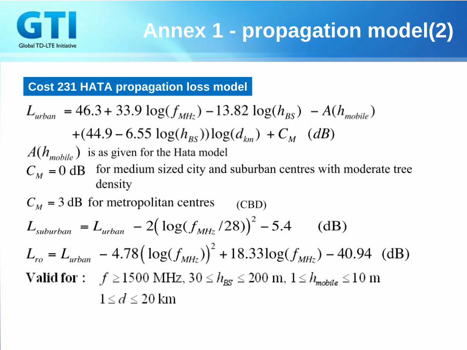
Cost 231 HATA propagation loss model
Annex 1 - propagation model(2)
Annex 2 ‐
Scenario Definitions
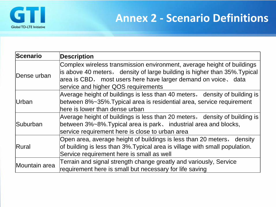
Scenario Description
Dense urban
Complex wireless transmission environment, average height of buildings is above 40 meters, density of large building is higher than 35%.Typical area is CBD, most users here have larger demand on voice、 data service and higher QOS requirements
UrbanAverage height of buildings is less than 40 meters, density of building is between 8%~35%.Typical area is residential area, service requirement here is lower than dense urban
SuburbanAverage height of buildings is less than 20 meters, density of building is between 3%~8%.Typical area is park、 industrial area and blocks, service requirement here is close to urban area
Rural Open area, average height of buildings is less than 20 meters, density of building is less than 3%.Typical area is village with small population. Service requirement here is small as well
Mountain area Terrain and signal strength change greatly and variously, Service requirement here is small but necessary for life saving

GTI TaskforceMulti-Antenna Solutions &
SpecificationsReport
CMCCTF Lead: Ma XinDate: 16,April
Basic TF information
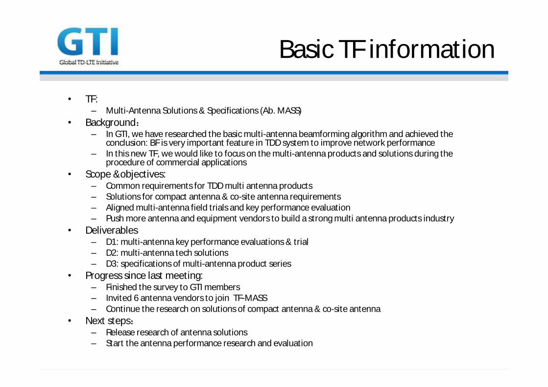
• TF: – Multi-Antenna Solutions & Specifications (Ab. MASS)
• Background:– In GTI, we have researched the basic multi-antenna beamforming algorithm and achieved the
conclusion: BF is very important feature in TDD system to improve network performance– In this new TF, we would like to focus on the multi-antenna products and solutions during the
procedure of commercial applications• Scope &objectives:
– Common requirements for TDD multi antenna products– Solutions for compact antenna & co-site antenna requirements– Aligned multi-antenna field trials and key performance evaluation– Push more antenna and equipment vendors to build a strong multi antenna products industry
• Deliverables– D1: multi-antenna key performance evaluations & trial– D2: multi-antenna tech solutions– D3: specifications of multi-antenna product series
• Progress since last meeting:– Finished the survey to GTI members– Invited 6 antenna vendors to join TF-MASS – Continue the research on solutions of compact antenna & co-site antenna
• Next steps:– Release research of antenna solutions– Start the antenna performance research and evaluation
3 main targets of TF:MASS
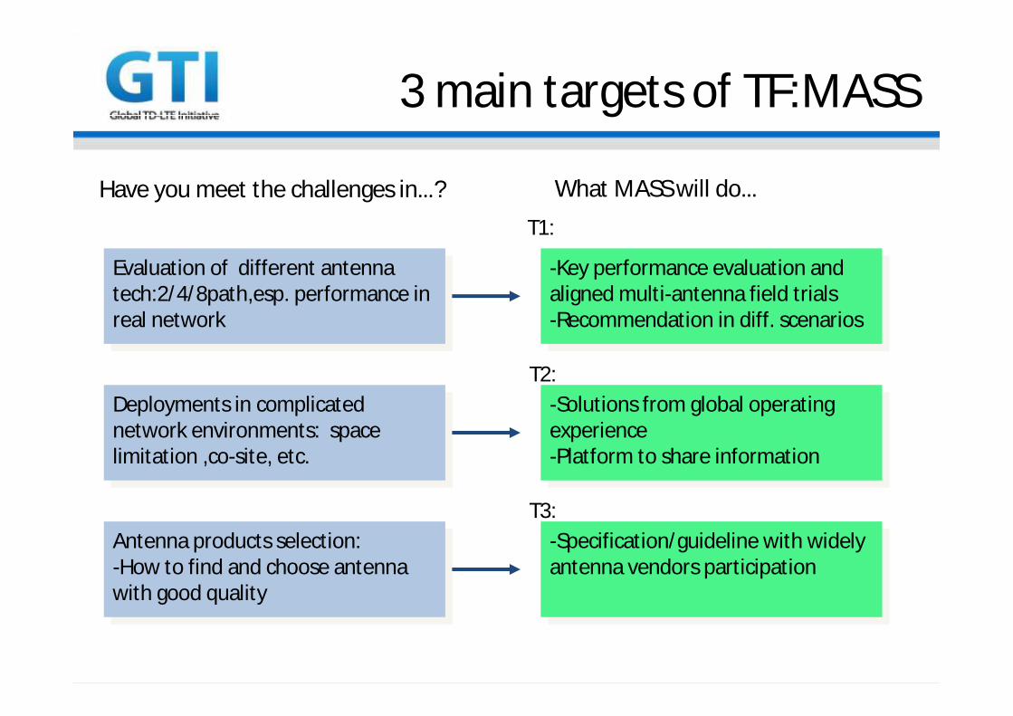
Have you meet the challenges in…? What MASS will do…
Evaluation of different antenna tech:2/4/8path,esp. performance in real network
Deployments in complicated network environments: space limitation ,co-site, etc.
-Key performance evaluation and aligned multi-antenna field trials-Recommendation in diff. scenarios
-Solutions from global operating experience-Platform to share information
Antenna products selection:-How to find and choose antenna with good quality
-Specification/guideline with widely antenna vendors participation
T1:
T2:
T3:
multi-antenna performance introduction and comparison
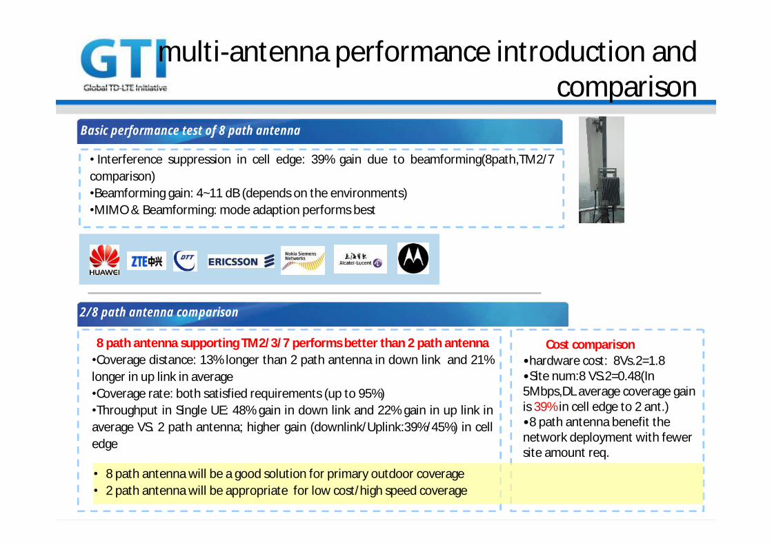
• Interference suppression in cell edge: 39% gain due to beamforming(8path,TM2/7 comparison)•Beamforming gain: 4~11 dB (depends on the environments)•MIMO & Beamforming: mode adaption performs best
Basic performance test of 8 path antenna
8 path antenna supporting TM2/3/7 performs better than 2 path antenna•Coverage distance: 13% longer than 2 path antenna in down link and 21% longer in up link in average•Coverage rate: both satisfied requirements (up to 95%)•Throughput in Single UE: 48% gain in down link and 22% gain in up link in average VS. 2 path antenna; higher gain (downlink/Uplink:39%/45%) in cell edge
2/8 path antenna comparison
•hardware cost: 8Vs.2=1.8•Site num:8 VS.2=0.48(In 5Mbps,DL average coverage gain is 39% in cell edge to 2 ant.)•8 path antenna benefit the network deployment with fewer site amount req.
• 8 path antenna will be a good solution for primary outdoor coverage • 2 path antenna will be appropriate for low cost/high speed coverage
Cost comparison
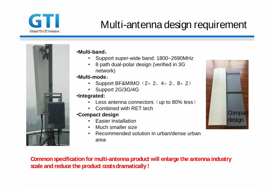
Multi-antenna design requirement
•Multi-band:• Support super-wide band: 1800~2690MHz • 8 path dual-polar design (verified in 3G
network)•Multi-mode:
• Support BF&MIMO(2×2、4×2、8×2)• Support 2G/3G/4G
•Integrated:• Less antenna connectors(up to 80% less)• Combined with RET tech
•Compact design• Easier installation • Much smaller size• Recommended solution in urban/dense urban
area
Common specification for multi-antenna product will enlarge the antenna industry scale and reduce the product costs dramatically !
Compactdesign
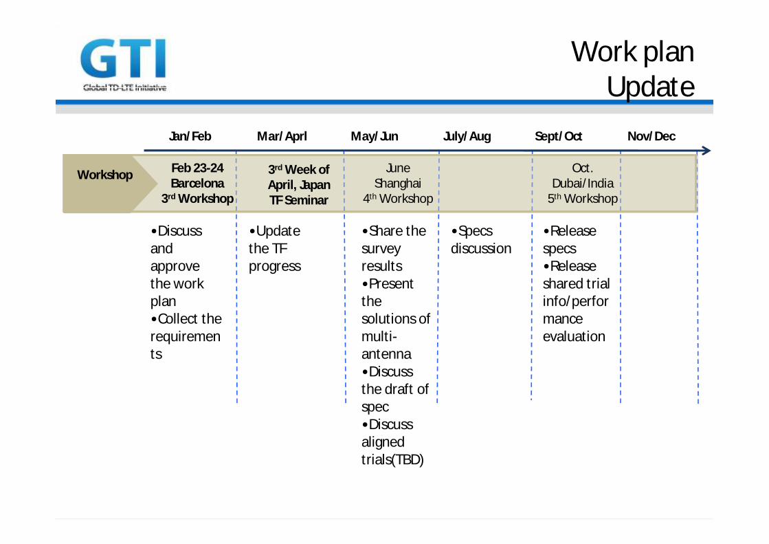
Jan/Feb Mar/Aprl May/Jun July/Aug Sept/Oct Nov/Dec
Workshop Feb 23-24Barcelona
3rd Workshop
JuneShanghai
4th Workshop
Oct.Dubai/India
5th Workshop
3rd Week of April, JapanTF Seminar
Work planUpdate
•Discuss and approve the work plan•Collect the requirements
•Update the TF progress
•Share the survey results•Present the solutions of multi-antenna•Discuss the draft of spec•Discuss aligned trials(TBD)
•Specs discussion
•Release specs•Release shared trial info/performance evaluation

Jan/Feb Mar/Aprl May/Jun July/Aug Sept/Oct Nov/Dec
Main activities
Work plan-output
Survey onReq.
Date
By:
Output:
End of Feb
Email/call
Survey results
Multi antenna evaluation(T1)
F2F meeting
Mid April
D1:evluation& trial
Multi antenna solutions(T2)
June
F2Fmeeting/demonstration
D2:solutions
Spec discussion(T3)
Mid Aug
Conf. call
D3:specs
F2F meeting
Oct
Final release
Conf. call
Nov
Spec discussion(T3)


![Dynamic TDD in LTE Small Cells - Aalto TD-Long-Term Evolution (LTE) small cells. We uti-lize the TD-LTE test platform [2] and study the impact of dynamic TD-LTE subframe configuration](https://static.documents.pub/doc/80x56/5add4ea07f8b9ae1408cc58e/dynamic-tdd-in-lte-small-cells-aalto-td-long-term-evolution-lte-small-cells.jpg)


